Embed Size (px)
Citation preview
ZBeeMeRA ZigBee Automatic Meter Reading System
André Duarte Monteiro Glória
Dissertation submitted to obtain the Master (MSc) degree inElectrical and Computer Engineering
Jury
President:
Supervisor:
Co-Supervisor:
Member:
Prof. Marcelino Bicho dos Santos
Prof. Maria Helena da Costa Matos Sarmento
Prof. Mário Serafim dos Santos Nunes
Prof. Francisco André Corrêa Alegria
October 2010

ii

Acknowledgements
My first words of appreciation go to my supervisor Prof. Helena Sarmento, without her this
dissertation would never seen day light. I thank her for the patience, support, criticism, suggestions,
patience1 and time. To my co-supervisor Prof. Mário Serafim Nunes I thank him for sharing his
technological insight and market knowledge, and also for his continued support.
Other people directly helped in this dissertation. My many thanks to Bithium, namely António
Muchaxo for the discussions, ideas, support and access to Bithium’s resources, and Sérgio Martins
for the soldering tips and help with PCB corrections and testing. To Luís Silva for the PCB tips and
revision. Also to António Moreira for the explanations about antennas and EDP - Energias de
Portugal for providing the energy meters used in this work.
To all my friends and colleagues I thank their time, support, help and laughs, in better and worst
times, not only throughout this dissertation, but throughout my entire graduation journey.
Finally and more importantly, to my family that always believed in me and whom I deprived from
my attention several times. Your understanding, huge support and comfort is invaluable.
Many thanks to you all, you helped me more than you may realise.
1Yes, patience appears twice and believe me when I say it is probably not enough.
iii

iv
Abstract
To produce and distribute power in a even more efficient manner, with high reliability and trans-
parency, utilities are currently looking for more control over the electric grid and power demand.
Utilities also want to provide consumers with information that compels them to save energy. Auto-
matic Meter Infrastructure (AMI) aims to solve this problem. AMI refers to a metering infrastructure
that automatically records and reports customer consumption, hourly or even more frequently in a
day.
This dissertation proposes a wireless solution, using ZigBee, to AMI over a building or neigh-
bourhood. Hardware and software were developed to implement it. The infrastructure is supported
by a ZigBee mesh network, where energy meters are the nodes and an unique concentrator en-
ables the communication between the meters and the utility. A ZigBee module was developed to
connect to the energy meter though an RS-232 interface and to implement the concentrator. The
software supports the hardware and the metering infrastructure. Access to the metering information
and interaction with the Wireless Sensor Network (WSN) can be done through a web interface.
A prototype with four nodes was set-up inside a building. ZigBee demonstrated to be a good
solution to implement the required bi-directional communications. Using Energy Meter Sensor
Nodes (EMSeNs) with routing capabilities and an unique concentrator to aggregate metering data,
permits to achieve a low cost system without reducing performance.
Keywords
PCB, Electronic Design, AMI, AMR, Smart Grid, ZigBee
v

vi

Resumo
Para produzir e distribuir energia eléctrica com grande eficácia, fiabilidade e transparência, os
operadores energéticos (utilities) pretendem actualmente ter um maior controlo sobre a rede eléc-
trica e o consumo de energia. Pretendem ainda fornecer informação aos seus clientes, para que
estes poupem energia. A Automatic Meter Infrastructure (AMI) pretende solucionar este problema.
Esta define uma infra-estrutura com contadores, que de forma automática registam e transmitem
o consumo de energia de hora em hora, ou de forma ainda mais frequente.2
Esta dissertação propõe uma solução sem fios, utilizando ZigBee, para implementar AMI num
edifício ou vizinhança. Foram desenvolvidos equipamentos e programas para a implementar. A
infra-estrutura é suportada numa rede (mesh) ZigBee, na qual os contadores são nós e um único
concentrador permite a comunicação entre estes e o operador de energia. Um módulo ZigBee foi
desenvolvido para comunicar via RS-232 com o contador e para implementar o concentrador. Os
programas desenvolvidos suportam tanto o módulo como toda a infra-estrutura de telecontagem.
O acesso aos consumos e a interacção com a rede de sensores pode ser realizada através de
uma página na internet.
Um protótipo com quatro nós foi instalado num edifício. O ZigBee demonstrou ser uma boa
solução para implementar a comunicação bidirecional necessária. O uso de contadores dotados
de ZigBee com capacidades de reencaminhamento de mensagens, aliado ao uso de um único
concentrador que agrega a informação dos consumos, permite obter um sistema de baixo custo
sem comprometer desempenho.
Palavras Chave
Circuito Impresso, Projecto de Electrónica, AMI, AMR, IEC 62056-21, Rede Eléctrica Inteligente,
ZigBee
2Esta funcionalidade pode ser designada de telecontagem.
vii

viii

Contents
1 Introduction 1
2 ZigBee Technology 5
2.1 IEEE 802.15.4 . . . . . . . . . . . . . . . . . . . . . . . . . . . . . . . . . . . . . 6
2.1.1 The Physical Layer . . . . . . . . . . . . . . . . . . . . . . . . . . . . . . . 6
2.1.2 The Medium Access Layer . . . . . . . . . . . . . . . . . . . . . . . . . . . 6
2.2 ZigBee . . . . . . . . . . . . . . . . . . . . . . . . . . . . . . . . . . . . . . . . . . 9
2.2.1 The Network Layer . . . . . . . . . . . . . . . . . . . . . . . . . . . . . . . 9
2.2.2 The Application Layer . . . . . . . . . . . . . . . . . . . . . . . . . . . . . . 11
2.3 ZigBee Pro . . . . . . . . . . . . . . . . . . . . . . . . . . . . . . . . . . . . . . . . 12
2.4 6LoWPAN . . . . . . . . . . . . . . . . . . . . . . . . . . . . . . . . . . . . . . . . 13
3 ZBeeMeR System 15
3.1 ZBeeMeR Architecture . . . . . . . . . . . . . . . . . . . . . . . . . . . . . . . . . 15
3.2 Hardware . . . . . . . . . . . . . . . . . . . . . . . . . . . . . . . . . . . . . . . . 16
3.2.1 The ZigBee SoC . . . . . . . . . . . . . . . . . . . . . . . . . . . . . . . . . 17
3.2.2 Power System . . . . . . . . . . . . . . . . . . . . . . . . . . . . . . . . . . 19
3.2.3 Antennas . . . . . . . . . . . . . . . . . . . . . . . . . . . . . . . . . . . . . 21
3.2.4 Serial Communication and Extra Memory . . . . . . . . . . . . . . . . . . . 22
3.2.5 Printed Circuit Board . . . . . . . . . . . . . . . . . . . . . . . . . . . . . . 22
3.3 Prototype . . . . . . . . . . . . . . . . . . . . . . . . . . . . . . . . . . . . . . . . 24
3.3.1 Devices . . . . . . . . . . . . . . . . . . . . . . . . . . . . . . . . . . . . . 24
3.3.2 Features . . . . . . . . . . . . . . . . . . . . . . . . . . . . . . . . . . . . . 25
3.4 Software . . . . . . . . . . . . . . . . . . . . . . . . . . . . . . . . . . . . . . . . . 27
3.4.1 Nodes Software . . . . . . . . . . . . . . . . . . . . . . . . . . . . . . . . . 27
3.4.2 EMSeNs and Network Extender Nodes . . . . . . . . . . . . . . . . . . . . 29
3.4.3 Concentrator . . . . . . . . . . . . . . . . . . . . . . . . . . . . . . . . . . . 31
3.4.4 Web Interface . . . . . . . . . . . . . . . . . . . . . . . . . . . . . . . . . . 33
4 Tests and Results 35
4.1 Module Tests . . . . . . . . . . . . . . . . . . . . . . . . . . . . . . . . . . . . . . 35
4.2 ZBeeMeR Tests . . . . . . . . . . . . . . . . . . . . . . . . . . . . . . . . . . . . . 40
ix

5 Conclusions 43
5.1 Future Work . . . . . . . . . . . . . . . . . . . . . . . . . . . . . . . . . . . . . . . 44
References 48
Appendices
Appendix A ZigBee Solutions for Product Development 51
Appendix B Ni-MH and Li-ion batteries 63
B.1 Ni-MH batteries . . . . . . . . . . . . . . . . . . . . . . . . . . . . . . . . . . . . . 63
B.2 Li-ion batteries . . . . . . . . . . . . . . . . . . . . . . . . . . . . . . . . . . . . . . 64
Appendix C PCB Project Dossier 67
C.1 PCB Layout . . . . . . . . . . . . . . . . . . . . . . . . . . . . . . . . . . . . . . . 68
C.2 Assembly . . . . . . . . . . . . . . . . . . . . . . . . . . . . . . . . . . . . . . . . 71
C.2.1 Bill of Materials (BOM) . . . . . . . . . . . . . . . . . . . . . . . . . . . . . 71
C.2.2 Component References . . . . . . . . . . . . . . . . . . . . . . . . . . . . . 73
C.2.3 Top Component Placement . . . . . . . . . . . . . . . . . . . . . . . . . . . 74
C.2.4 Schematics . . . . . . . . . . . . . . . . . . . . . . . . . . . . . . . . . . . 75
C.3 Stencil . . . . . . . . . . . . . . . . . . . . . . . . . . . . . . . . . . . . . . . . . . 78
C.3.1 Board Panel Stencil . . . . . . . . . . . . . . . . . . . . . . . . . . . . . . . 78
Appendix D Communications in the ZBeeMeR prototype 79
x
List of Tables
1.1 Comparison of technologies . . . . . . . . . . . . . . . . . . . . . . . . . . . . . . 2
2.1 Frequency ranges, data rates and modulations. . . . . . . . . . . . . . . . . . . . . 6
3.1 ZigBee SoCs - Selection from the initial survey. . . . . . . . . . . . . . . . . . . . . 17
3.2 Comparison of Antenna Solutions. . . . . . . . . . . . . . . . . . . . . . . . . . . . 21
4.1 Deviations from the centre channel frequency. . . . . . . . . . . . . . . . . . . . . . 37
4.2 Power measurements over a 1 meter distance. . . . . . . . . . . . . . . . . . . . . 39
4.3 Power measurements over a 2 meters distance. . . . . . . . . . . . . . . . . . . . . 39
4.4 Power measurements over a 5 meters distance. . . . . . . . . . . . . . . . . . . . . 39
A.1 ZigBee chip solutions. . . . . . . . . . . . . . . . . . . . . . . . . . . . . . . . . . . 52
A.2 Detailed information of ZigBee single chip solutions. . . . . . . . . . . . . . . . . . 53
A.3 ZigBee development kits. . . . . . . . . . . . . . . . . . . . . . . . . . . . . . . . . 54
A.4 ZigBee modules and their features. . . . . . . . . . . . . . . . . . . . . . . . . . . 61
C.1 Bill of Materials (BOM) − Supplier: Digikey . . . . . . . . . . . . . . . . . . . . . . 71
C.2 Bill of Materials (BOM) − Supplier: Farnell . . . . . . . . . . . . . . . . . . . . . . 72
C.3 Component references and values. . . . . . . . . . . . . . . . . . . . . . . . . . . . 73
xi

xii
List of Figures
2.1 ZigBee stack architecture. . . . . . . . . . . . . . . . . . . . . . . . . . . . . . . . 5
2.2 Message flow in a Star network topology. . . . . . . . . . . . . . . . . . . . . . . . 7
2.3 Parent-Child associations in a Clustered Stars network topology. . . . . . . . . . . 7
2.4 A superframe structure. . . . . . . . . . . . . . . . . . . . . . . . . . . . . . . . . . 8
3.1 AMI based on a ZigBee mesh network. . . . . . . . . . . . . . . . . . . . . . . . . 16
3.2 The ZigBee module architecture. . . . . . . . . . . . . . . . . . . . . . . . . . . . . 17
3.3 ZigBee module’s power supply diagram. . . . . . . . . . . . . . . . . . . . . . . . . 20
3.4 Battery charging circuit. . . . . . . . . . . . . . . . . . . . . . . . . . . . . . . . . . 21
3.5 Layer stack-up on a 4-layer PCB. . . . . . . . . . . . . . . . . . . . . . . . . . . . . 23
3.6 Digital and analog separation on the PCB. . . . . . . . . . . . . . . . . . . . . . . . 23
3.7 Power connection through bypass capacitor. . . . . . . . . . . . . . . . . . . . . . 24
3.8 The ZigBee module. . . . . . . . . . . . . . . . . . . . . . . . . . . . . . . . . . . . 24
3.9 Prototype Network Devices. . . . . . . . . . . . . . . . . . . . . . . . . . . . . . . 25
3.10 ZBeeMeR Software Architecture − Protocols Involved. . . . . . . . . . . . . . . . . 26
3.11 ZBeeMeR Software Architecture − Exchanged Information. . . . . . . . . . . . . . 27
3.12 Software architecture of the ZigBee modules. . . . . . . . . . . . . . . . . . . . . . 27
3.13 EMSeNs and network extender nodes program flowchart. . . . . . . . . . . . . . . 30
3.14 Concentrator program flowchart − ZigBee module. . . . . . . . . . . . . . . . . . . 31
3.15 Concentrator program flowchart − PC. . . . . . . . . . . . . . . . . . . . . . . . . . 32
3.16 Web interface architecture overview. . . . . . . . . . . . . . . . . . . . . . . . . . . 33
3.17 Web Interface. . . . . . . . . . . . . . . . . . . . . . . . . . . . . . . . . . . . . . . 34
4.1 Module emissions over a 3GHz frequency span. . . . . . . . . . . . . . . . . . . . 36
4.2 Module unmodulated emissions. . . . . . . . . . . . . . . . . . . . . . . . . . . . . 36
4.3 Module O-QPSK modulated emissions. . . . . . . . . . . . . . . . . . . . . . . . . 38
4.4 Prototype network structure with nodes location. . . . . . . . . . . . . . . . . . . . 40
C.1 PCB layers − Electrical connections and components. . . . . . . . . . . . . . . . . 68
C.2 PCB layers − Solder and solder mask pads. . . . . . . . . . . . . . . . . . . . . . 69
C.3 PCB layers − Drills and component labels. . . . . . . . . . . . . . . . . . . . . . . 70
C.4 Component Placement. . . . . . . . . . . . . . . . . . . . . . . . . . . . . . . . . . 74
C.5 Schematic (1 of 2). . . . . . . . . . . . . . . . . . . . . . . . . . . . . . . . . . . . 76
xiii

C.6 Schematic (2 of 2). . . . . . . . . . . . . . . . . . . . . . . . . . . . . . . . . . . . 77
C.7 Stencil. . . . . . . . . . . . . . . . . . . . . . . . . . . . . . . . . . . . . . . . . . . 78
D.1 EMSeN association with the network concentrator. . . . . . . . . . . . . . . . . . . 80
D.2 EMSeN association with a network extender node. . . . . . . . . . . . . . . . . . . 81
D.3 EMSeN responding to a concentrator request. . . . . . . . . . . . . . . . . . . . . 82
D.4 EMSeN performing a route request and then sending data. . . . . . . . . . . . . . . 83
xiv

Acronyms
AC Alternate CurrentACK AcknowledgementADC Analog-to-Digital ConverterAES Advanced Encryption StandardAF Application FrameworkAMI Automatic Meter InfrastructureAMR Automatic Meter ReadingAPL Application LayerAPS Application Support SublayerAODV Ad hoc On-demand Distance VectorARM Advanced Reduced Instruction Set Computing MachineASK Amplitude Shift KeyingBOM Bill of MaterialsBPSK Binary Phase-Shift KeyingCAP Contention Access PeriodCCM Counter with CBC-MACCCM* Extension of CCMCFP Contention Free PeriodCRC-16 Cyclic Redundancy Check 16CSMA/CA Carrier Sense Multiple Access with Collision AvoidanceDC Direct CurrentDES Data Encryption StandardDLMS Device Language Message SpecificationDSSS Direct Sequence Spread SpectrumEMSeN Energy Meter Sensor NodeFFD Full Function DeviceGPRS General Packet Radio ServiceGTS Guaranteed Time SlotGSM Global System for Mobile CommunicationsHAL Hardware Abstraction LayerID IdentificationIETF Internet Engineering Task ForceI/O Input/OutputIP Internet Protocol
xv

IPv4 Internet Protocol version 4IPv6 Internet Protocol version 6kBs KilobytesLDO Low Drop-OutLGA Land Grid ArrayLi-ion Lithium-IonLMP Link Management ProtocolLQI Link Quality IndicatorMAC Medium Access ControlMCU Micro-controller UnitMMCX Micro-miniature CoaxialMTU Maximum Transmission UnitNi-MH Nickel-metal HydrideNWK Network LayerO-QPSK Offset Quadrature Phase-Shift KeyingPAN Personal Area NetworkPCB Printed Circuit BoardPHY Physical LayerPIN Personal Identification NumberPiP Platform in PackagePLC Power Line CommunicationsPSSS Parallel Sequence Spread SpectrumRAM Random Access MemoryRFD Reduced Function DeviceRF Radio FrequencyRISC Reduced Instruction Set ComputingROM Read-only MemoryRSSI Received Signal Strength IndicatorSCI Synchronous Communications InterfaceSE Smart Energy ProfileSIM Subscriber Identity ModuleSiP System in a PackageSMD Surface Mounted DeviceSoC System on a ChipSPI Serial Peripheral InterfaceTDMA Time Division Multiple AccessTI Texas InstrumentsTTL Transistor-transistor LogicUART Universal Asynchronous Receiver/TransmitterWAN Wide Area NetworkWiMax Worldwide Interoperability for Microwave AccessWPA Wi-Fi Protected AccessWSN Wireless Sensor NetworkZCL Zigbee Cluster LibraryZDO Zigbee Device ObjectZDP ZigBee Device Profile
xvi

Chapter 1
Introduction
Today’s electric grids are outdated. The traditional manual energy meter reading wastes, time
and manpower. Its unreliability and low frequency of occurrence produces data that is both, useless
for energy production/distribution real-time decisions and for accurate consumption measurements
and billing. A better control over the energy production, distribution and consumption is required.
In this scenario, environmental sustainability is pushing us to a more efficient use of earth’s natural
resources, leading us to expand the use of green/renewable energies, and turning electric cars [1,2]
into a future reality. In addition, micro-generation is also gaining momentum as a means to catch
up to the ever increasing power demand [3].
The electric grids components, energy production plants, distribution lines and loads need to
become “smart”. Smart grid is a new concept that refers to technologies devoted to modernising
the electric grids, creating an intelligent system that responds to peaks of energy usage, controls
power demand, better incorporates local production of clean energy and accurately measures con-
sumption. Automatic Meter Reading (AMR) and Automatic Meter Infrastructure (AMI) are smart
metering technologies that contribute to the smart grid.
AMR technology enables energy meters to autonomously report customer consumption, hourly
or even more frequently in a day, while AMI provides an infrastructure to aggregate, record and send
that information to a service provider. AMI goes even further, it creates a two-way network between
the smart energy meters and the service provider, allowing individuals and companies to improve
their energy usage. In-home energy displays, thermostats, light switches and load controllers are
already a reality [4]. Utilities also benefit from this two-way networking since it improves reliability,
and allows for dynamic billing and appliances control.
The communication technologies, either wired or wireless, are a key element in smart meter-
ing. They will allow remote access to the metering data, remote configuration of energy meters and
even remote firmware updates. For such technologies to succeed, they must promote interoper-
ability1, create robust and reliable networks and have a low installation and maintenance cost [5].
Wired connections, using Power Line Communications (PLC) in AMR systems already exist [6–8].
However, their reliability is highly affected by the noise generated from appliances [9] and several
1Open Standards being the only way to guarantee interoperability.
1
disturbances that can occur in the electric grid [10].
Wireless technologies are becoming more common since they avoid the hassle and cost of
installing and maintaining a cable infrastructure to support a network. Regarding AMI/AMR, GPRS,
Wi-Fi, Bluetooth and ZigBee are the most promising wireless technologies. General Packet Radio
Service (GPRS) [11, 12] has the advantage of using an already existing infrastructure, but it is an
expensive solution. Hardware costs as well as power consumption (transmission requires bursts
of more than 2 A) are higher than in other wireless technologies. In addition, utilities need to pay
for the communications service, subscribing it from a telecoms provider. These disadvantages are
important since utilities look for cost effective solutions [13].
As Wi-Fi routers already exist in the majority of homes and offices, utilities can use Wi-Fi en-
abled meters to communicate metering data. This could potentially save installation costs but it
relies heavily on the costumer. The costumer must configure the wireless connection, making the
utility partially loose control over the system. One possible solution, involving Wi-Fi is relying on
the upcoming Worldwide Interoperability for Microwave Access (WiMax) technology [13, 14]. This
combination can be a good solution for AMI/AMR, but the future of WiMax is still uncertain [15].
Solutions using Bluetooth [16, 17] take advantage of the low power nature of this technology.
However, Bluetooth is intended to short distance cable replacement being unable to form large
networks. A Bluetooth network can bridge together piconets of 8 nodes to form larger networks
(called a scatternet), but neither the mechanism nor the resulting topology are defined by the
Bluetooth standard [18]. This allows manufacturers to implement different algorithms (examples
in [19, 20]), not promoting interoperability, which will hinder the proliferation of the technology to
in-home appliances.
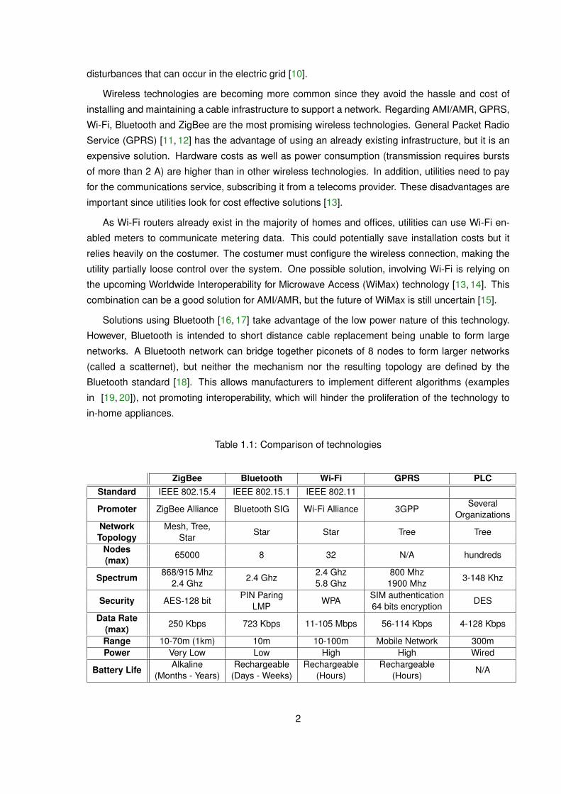
Table 1.1: Comparison of technologies
ZigBee Bluetooth Wi-Fi GPRS PLCStandard IEEE 802.15.4 IEEE 802.15.1 IEEE 802.11
Promoter ZigBee Alliance Bluetooth SIG Wi-Fi Alliance 3GPPSeveral
OrganizationsNetwork Mesh, Tree,
Star Star Tree TreeTopology Star
Nodes65000 8 32 N/A hundreds
(max)
Spectrum868/915 Mhz
2.4 Ghz2.4 Ghz 800 Mhz
3-148 Khz2.4 Ghz 5.8 Ghz 1900 Mhz
Security AES-128 bitPIN Paring
WPASIM authentication
DESLMP 64 bits encryption
Data Rate250 Kbps 723 Kbps 11-105 Mbps 56-114 Kbps 4-128 Kbps
(max)Range 10-70m (1km) 10m 10-100m Mobile Network 300mPower Very Low Low High High Wired
Battery LifeAlkaline Rechargeable Rechargeable Rechargeable
N/A(Months - Years) (Days - Weeks) (Hours) (Hours)
2

The last alternative technology, ZigBee, is the adopted in this thesis. Its technological fea-
tures [21,22] (see table 1.1) surpass that of the other referred technologies, making it an attractive
solution to support the smart grid.
ZigBee is a low-power, low-cost wireless technology being recently used as a de facto standard
for Wireless Sensor Network (WSN). Large reliable deployments are now in place implementing
ad-hoc WSN, such as, room locks in Mandalay Bay Hotels [23], equipment tracking at Tri-City
Medical Center [24] and metering [25]. ZigBee Alliance, which promotes ZigBee, is developing
profiles and enforcing certifications to achieve interoperability, making ZigBee very attractive for
home automation, telecom services and smart metering. In 2008, ZigBee Alliance specified the
Smart Energy Profile (SE) profile that provides device descriptions and standard practises for de-
mand response, load control, pricing and metering applications, in order to allow interoperability
among ZigBee products produced by various manufacturers.
More recently, ZigBee Alliance stated [26] it would incorporate global IT standards from the
Internet Engineering Task Force (IETF) into the SE, to provide applications with native IP support.
They also announced a collaboration with Wi-Fi Alliance [27], to use 6LoWPAN in the SE. 6LoW-
PAN is a compression mechanism to enable the use of IPv6 in IEEE 802.15.4 based networks.
Other AMI/AMR implementations, using ZigBee, have been reported. In [28, 29], an AMR
system is presented. These works use a dedicated ZigBee routers infrastructure to create the
mesh wireless network, and ZigBee end devices to interface with the meters. In [29], GPRS is
used to make the metering data available, while in [28] they state any wired or wireless protocol
could be used.
In [30] a dedicated router infrastructure is also proposed for message handling. They assume
all communications between the meters, the appliances and the costumers will always require in-
formation to go to the service provider and back. Therefore, they employ a load balancing scheme,
by simultaneously using more than one channel to send data, to avoid communications congestion
and reduce message delays.
A metering module is developed, in [31], that interfaces with a data acquisition module and not
with existing meters. They consider a star network for the measuring infrastructure and the data
collected is then stored on the concentrator. No methods to send that data to the service provider
are presented.
At a larger scale there is the pilot project in Goteborg [21] whose purpose, is to create an AMI
system, over the entire city, using ZigBee. Unfortunately, the information available is not enough
for a comparison with this thesis work.
The system implemented in this thesis, interfaces with existing digital energy meters enabling
them to communicate through ZigBee. Using Device Language Message Specification (DLMS), it
can not only retrieve voltage/current/power measurements from the energy meter but it can also
configure it, which is a clear future advantage over systems that use data acquisition modules
directly on the power lines or count the meters’ pulses. Communications are supported by a full
mesh ZigBee network (every meter node is a ZigBee router), so no router infrastructure, dedicated
to routing messages, is required. Although using ZigBee end devices produces the lowest power
3
consumption solution (ZigBee end devices can sleep while ZigBee routers cannot), it increases
costs due the increase of devices needed. No load balancing scheme is employ, like in [30], our
system’s nodes are flexible enough to implement a costumer-meter communication that does not
required constant utility queries, therefore lowering network traffic. Finally, the network concentrator
interacts with the service provider through ethernet, but any Wide Area Network (WAN) protocol
can be used.
Objectives
The main objective of this work is to develop an AMI/AMR system, using a ZigBee mesh WSN
that easily integrates with the existing infrastructure. The developed solution must provide a low-
cost upgrade to the systems already in place. To achieve the main objective, specific objectives are
defined:
- Analyse commercially available products on the market.
- Develop the hardware and software of a ZigBee module.
- Implement, in the ZigBee module, an interface to enable communication with commerciallyavailable energy meters.
- Choose and implement an antenna for the ZigBee module.
- Choose and implement a permanent power supply for the ZigBee module.
- Choose a type of rechargeable batteries to be used as a backup power supply and implementits charging circuit.
- Develop a platform to permit the system’s demonstration.
Dissertation Outline
The structure of this dissertation is as follows. Chapter 2 introduces the ZigBee technology,
detailing its physical characteristics, features and operation, and presenting a brief overview about
its evolution to 6LoWPAN. Chapter 3 details the work done to implement the ZBeeMeR system, in-
troducing the proposed architecture and then detailing hardware and software decisions. In Chap-
ter 4 the tests to validate the developed ZigBee module and the complete ZBeeMeR system are
presented, as well as some results. Finally, Chapter 5 concludes this dissertation by, evaluating the
initial objectives, criticising the obtained system and describing future work.
4
Chapter 2
ZigBee Technology
ZigBee aims to be a open and global standard to be used in low-cost, low-power, low data
rate and highly reliable monitoring and control wireless solutions. This specification [32] is sup-
ported by the ZigBee Alliance, that provides public application profiles and interoperability testing
specifications.
Like any other protocol, ZigBee has a stack of layers presented on figure 2.1. As depicted on
the figure, ZigBee is built on top of the IEEE 802.15.4 standard [33].
Application (APL) Layer
SecurityServiceProvider
Application Framework (AF)
Application 1(endpoint 1)
Application 240(endpoint 240)
Network (NWK) Layer
SecurityManagement
PacketRouting
NetworkAddressing
NetworkTopology
Medium Access Control (MAC) Layer
ChannelAssessment
NetworkMaintenance
ReliableData Transport
ZDO’sManagement
Plane
ZigBee Device Object (ZDO)
DeviceDiscovery
ApplicationMatching
NetworkManagement
Physical (PHY) Layer
868/915 MHz Radio 2.4 GHz Radio
IEEE 802.15.4
ZigBeeAlliance
Application Support Sublayer (APS)
APSSecurity
PacketFragmentation
PacketFiltering
BindingManagement
Figure 2.1: ZigBee stack architecture.
The IEEE 802.15.4 standard only defines two layers, the Physical Layer (PHY) and the Medium
Access Control (MAC). ZigBee defines the two other layers. The Network Layer (NWK) provides,
5
hierarchical/stochastic addressing, route discovery, forwarding, authentication and encryption. The
Application Layer (APL) provides message fragmentation and filtering, binding management and
another level of encryption. In the APL, the Zigbee Device Object (ZDO) also provides network
services like device and service discovery, and application matching.
Next sections summarise the ZigBee specification, focusing on the relevant subjects for this
thesis work.
2.1 IEEE 802.15.4
2.1.1 The Physical Layer
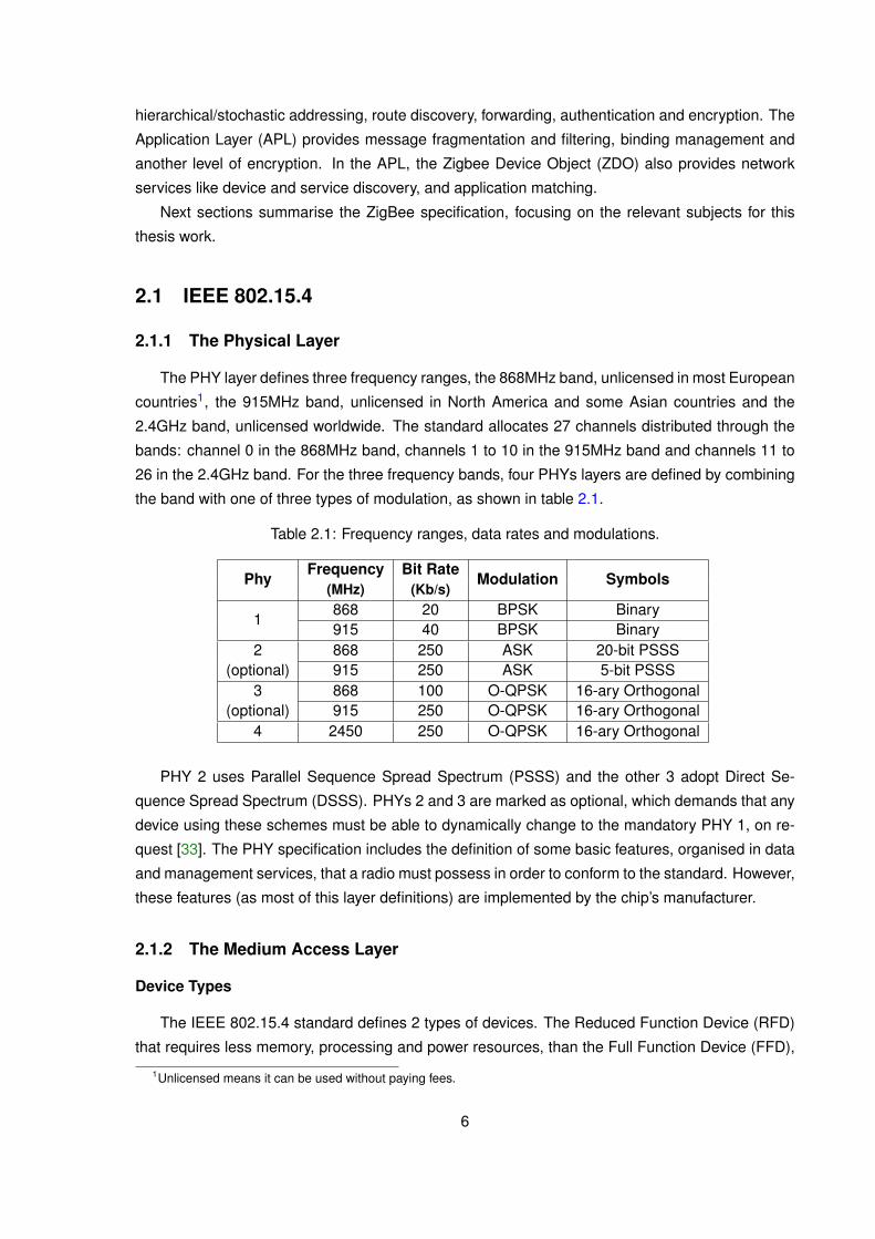
The PHY layer defines three frequency ranges, the 868MHz band, unlicensed in most European
countries1, the 915MHz band, unlicensed in North America and some Asian countries and the
2.4GHz band, unlicensed worldwide. The standard allocates 27 channels distributed through the
bands: channel 0 in the 868MHz band, channels 1 to 10 in the 915MHz band and channels 11 to
26 in the 2.4GHz band. For the three frequency bands, four PHYs layers are defined by combining
the band with one of three types of modulation, as shown in table 2.1.
Table 2.1: Frequency ranges, data rates and modulations.
PhyFrequency Bit Rate
Modulation Symbols(MHz) (Kb/s)
1868 20 BPSK Binary915 40 BPSK Binary
2 868 250 ASK 20-bit PSSS(optional) 915 250 ASK 5-bit PSSS
3 868 100 O-QPSK 16-ary Orthogonal(optional) 915 250 O-QPSK 16-ary Orthogonal
4 2450 250 O-QPSK 16-ary Orthogonal
PHY 2 uses Parallel Sequence Spread Spectrum (PSSS) and the other 3 adopt Direct Se-
quence Spread Spectrum (DSSS). PHYs 2 and 3 are marked as optional, which demands that any
device using these schemes must be able to dynamically change to the mandatory PHY 1, on re-
quest [33]. The PHY specification includes the definition of some basic features, organised in data
and management services, that a radio must possess in order to conform to the standard. However,
these features (as most of this layer definitions) are implemented by the chip’s manufacturer.
2.1.2 The Medium Access Layer
Device Types
The IEEE 802.15.4 standard defines 2 types of devices. The Reduced Function Device (RFD)
that requires less memory, processing and power resources, than the Full Function Device (FFD),
1Unlicensed means it can be used without paying fees.
6

which offers more features. FFDs are the only devices able to directly communicate with any other
device. They are also, the only devices capable of starting a network (task done by the special FFD
called coordinator), of forwarding packets and of giving permission to others devices to associate
with the network. A RFD only communicates and associates with one FFD at a time. RFDs are
usually sensor or actuator nodes, therefore implementing a reduced protocol set.
Due to their features, each device has a different role, FFDs create and maintain a network that
the RFDs use to report data.
Network Topologies
Coordinator
FFD
RFD
FFD
FFD
RFD
RFD
Figure 2.2: Message flow in a Star network topology.
FFDs and RFDs can interact in a star or in a peer-to-peer topology. The star network (figure 2.2)
is defined by a central node − the coordinator − and several satellite devices that join him to start
transmitting in the network. There are no direct associations between the satellite nodes, being all
the communications with the coordinator.
The peer-to-peer topology permits FFD devices to communicate directly with any other in range.
It does not define a network by itself, but permits various network structures with or without topolog-
ical restrictions. For example, in figure 2.3 a clustered stars network is presented. In this network
any two FFD in range, can communicate directly even with devices they are not associated with.
RFDs remain restricted to communicate with the FFD their associated with. As in every IEEE
802.15.4 network, one FFD is required to be the coordinator, responsible for starting the network.
CoordinatorFFD
FFD
FFD
RFD RFD
FFD
FFD
RFD
RFD
RFDRFDRFD
RFD
RFD
RFD
Figure 2.3: Parent-Child associations in a Clustered Stars network topology.
7
Communication Modes
The communication between network nodes is done according to either the beacon mode or the
non-beacon mode, using the Carrier Sense Multiple Access with Collision Avoidance (CSMA/CA)
method for medium access. The main distinction between both modes is the existence of a mech-
anism that allows for a synchronised/organised communication between the network nodes. In the
non-beacon mode, any time a node needs to send data over the air, it checks for channel activity2.
While activity is detected, it backs off for a random amount of time. As soon as no channel activity
exists, it starts transmitting. The transaction ends when the last byte has been sent. However, if an
Acknowledgement (ACK) was requested, the transaction only ends when the sender, successfully
receives it from the receiver. The receiver, after receiving the last byte of information, has less than
192µs to reply with an ACK message, without using CSMA/CA. So, the non-beacon mode has
no rules for communication other than the CSMA/CA scheme, and offers no mechanism for device
synchronisation.
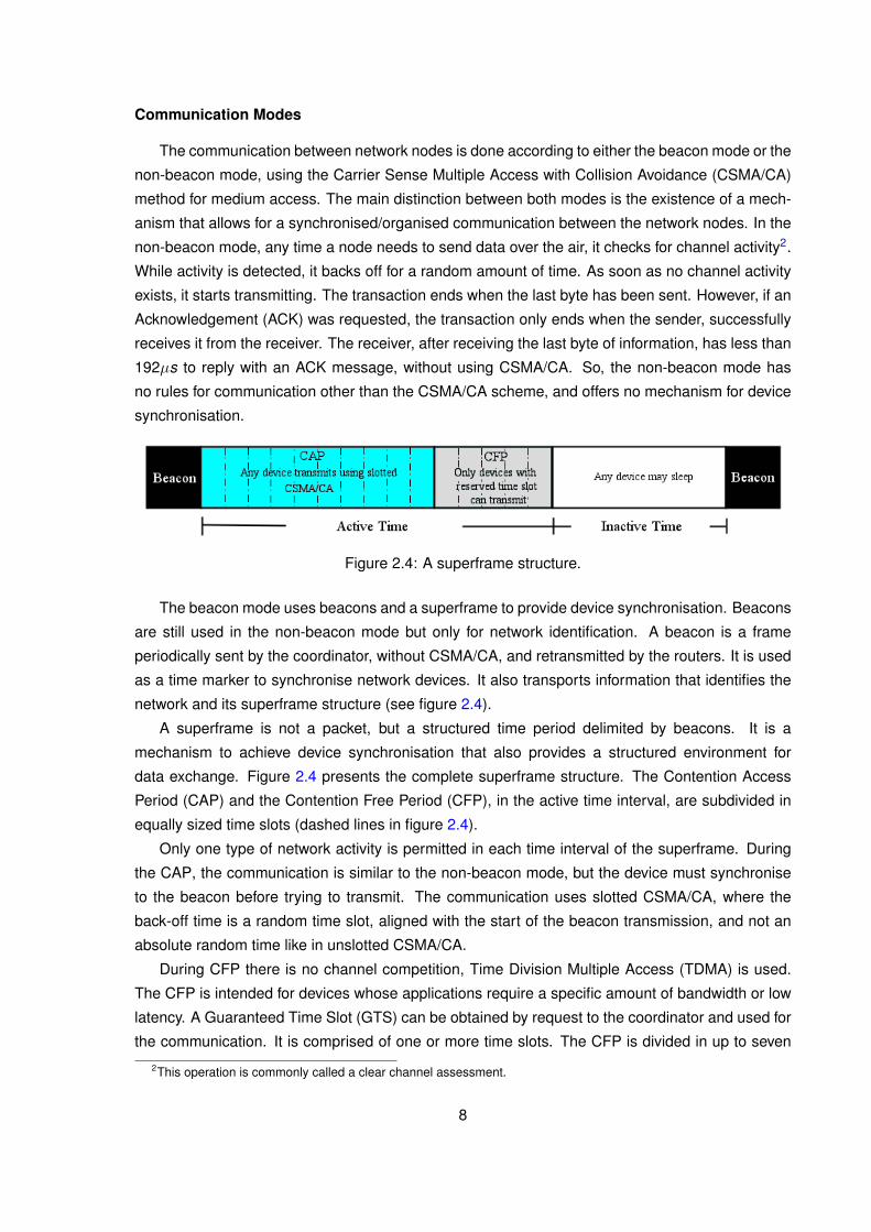
Figure 2.4: A superframe structure.
The beacon mode uses beacons and a superframe to provide device synchronisation. Beacons
are still used in the non-beacon mode but only for network identification. A beacon is a frame
periodically sent by the coordinator, without CSMA/CA, and retransmitted by the routers. It is used
as a time marker to synchronise network devices. It also transports information that identifies the
network and its superframe structure (see figure 2.4).
A superframe is not a packet, but a structured time period delimited by beacons. It is a
mechanism to achieve device synchronisation that also provides a structured environment for
data exchange. Figure 2.4 presents the complete superframe structure. The Contention Access
Period (CAP) and the Contention Free Period (CFP), in the active time interval, are subdivided in
equally sized time slots (dashed lines in figure 2.4).
Only one type of network activity is permitted in each time interval of the superframe. During
the CAP, the communication is similar to the non-beacon mode, but the device must synchronise
to the beacon before trying to transmit. The communication uses slotted CSMA/CA, where the
back-off time is a random time slot, aligned with the start of the beacon transmission, and not an
absolute random time like in unslotted CSMA/CA.
During CFP there is no channel competition, Time Division Multiple Access (TDMA) is used.
The CFP is intended for devices whose applications require a specific amount of bandwidth or low
latency. A Guaranteed Time Slot (GTS) can be obtained by request to the coordinator and used for
the communication. It is comprised of one or more time slots. The CFP is divided in up to seven
2This operation is commonly called a clear channel assessment.
8
GTSs and is an optional time interval.
Finally, the inactive period permits that any device, even routers, go to a sleep mode in order to
preserve power. The inactive time interval is also optional.
2.2 ZigBee
2.2.1 The Network Layer
ZigBee Network Layer (NWK) extends the IEEE 802.15.4 MAC layer (recall figure 2.1) by defin-
ing an addressing scheme and a routing mechanism. It also provides authentication and encryp-
tion. ZigBee types of nodes taxonomy, network topologies and modes of operation present some
differences to IEEE 802.15.4.
Differences to IEEE 802.15.4
ZigBee defines type of nodes based on their role rather than on hardware capabilities (FFD
and RFD). A ZigBee network has a coordinator, routers and/or end devices. The coordinator,
one per network, is a special case of a router. It is the sole responsible for starting a network
and for choosing/setting some key network parameters. After starting the network, the coordinator
behaves like a router, but its network address is always zero (0x0000). A router is a device capable
of extending the network coverage. It routes messages between other devices and enables new
devices to associate with it. The association allows the new device to join the network. Finally,
an end device is any device that is neither a router nor a coordinator. It only associates with one
device at a time, cannot directly exchange messages, and can sleep in order to save power. A
coordinator or router must be supported by a FFD while an end device can be either a FFD or a
RFD.
Tree and mesh network topologies, which use the peer-to-peer IEEE 802.15.4 feature, are
the two topologies defined by ZigBee . The tree topology is a particular case of the IEEE 802.15.4
clustered stars topology (figure 2.3), where hierarchical addressing and routing are used. The mesh
topology is the IEEE 802.15.4 clustered stars topology with mechanisms and rules to dynamically
achieve message routing. Routing is the ZigBee feature that eliminates the “in range” limitation of
communications on IEEE 802.15.4 networks.
Beacon or non-beacon modes of operation are, in ZigBee , network topology dependent. The
beacon mode is only supported on the tree topology, not being permitted in a mesh network topol-
ogy.
Addressing and Routing
Addressing in ZigBee networks is done using the Cskip algorithm [32]. This algorithm needs to
know, a priori, the maximum number of routers, the number of children3 and the tree depth. With
3Children are the sum of routers with end devices.
9

this information, ranges of 16 bit static addresses are computed and pre-programmed in all routers
and in the coordinator.4 Therefore, each device (apart from end devices) as a limited number of
addresses to attribute to joining devices. From each address the hierarchical location of a device
inside the network can be undoubtedly inferred.
Routing can follow one of two possible schemes, tree routing or a simplified version of Ad hoc
On-demand Distance Vector (AODV). Tree routing uses the implicit hierarchical information from
each device network address to route messages. Since in a hierarchical network, a message can
either go up or down, tree routing follows one condition. If the destination address is within the
device’s address range the message goes down, otherwise, it is sent up. Tree routing can be used
in any ZigBee network topology because their addressing algorithm is the same.
AODV creates routes when a node wants to send data to a receiver. The sender broadcasts
a route discovery request, if the destination address is not yet in its routing table. This request is
re-broadcasted again by every device that receives it, until the destination is reached. Once the
destination node is reached, the receiver sends a route request reply. This reply travels to the
requesting device and each device that forwards it along, stores an entry in its routing table.
Each routing table entry contains only the destination address and the address of the next hop
required to reach it.5 The sender can finally dispatch the message to its intended destination, over
the created route. A new route discovery request will only be initiated, on this same route, if any of
its devices fails. Any temporary routing information stored by nodes that did not forward the route
request reply, expire after a few seconds.
The ZigBee specification foresees the usage of a metric, (but only defines its scale) according
to which each device could report a number between one and seven representing the level of
confidence in receiving a message. This value would be summed up by the route request reply,
providing a measure for routes comparison.
Security
ZigBee NWK provides means for authentication and encryption built on top of the basic security
framework, AES encryption and CCM security modes, defined in IEEE 802.15.4. ZigBee protects
messages integrity by encryption according to AES-128 using the CCM* security mode. Though
CCM*, ZigBee combines encryption and authentication with a single key, while also supporting
messages that require only encryption.
Three different security keys can be used. A master key, to provide security between two
devices6, a link key, to protect the transport of data between two devices, and a shared network
key, for network wide security against outside attacks, at either data or infrastructure levels.
Keys can be pre-programmed in the devices or exchanged when a device joins the network.
They can also be periodically updated, to improve security. A device implementing the trust center,
4Although each device has a 64 bit unique identifier, that can be used for identification/communication, when in anetwork, communications use a 16 bit address.
5This way, each device only stores a portion of the route information, allowing for smaller routing tables and conse-quently smaller RAM requirements.
6Protects link key exchange.
10

is responsible for the network keys handling and maintenance, and also for admitting new devices
into the network.
2.2.2 The Application Layer
The Application Layer (APL), the last ZigBee layer (figure 2.1), is dedicated to support the
costumer/manufacturer application inside a ZigBee device. It is divided in three sections, the Appli-
cation Framework (AF), that allows for a single device to run many applications, the Zigbee Device
Object (ZDO), that provides several network services and the Application Support Sublayer (APS),
that provides message handling services.
Each device is defined by a profile, either public or private, that defines its application environ-
ment, its features and the clusters it uses for communication. Clusters are unique identifiers that
represent a collection of commands (or attributes), that are inputs and outputs of the application.7
Public profiles guarantee interoperability between different vendors for the same application envi-
ronment.8 The public Zigbee Cluster Library (ZCL) [34], an add-on to ZigBee profiles, is a collection
of clusters that retain their meaning across profiles. For example, the OnOff cluster that defines
how something can be turned off, on or toggled, can be used in a light switch, a garage door, valves
and any other device that can have these two states (on or off). This promotes interoperability by
re-use of clusters when a new application profile as to be defined.
An application is implemented as an application object and connects to the rest of the stack
through an endpoint, which makes it addressable within a device. The AF is the infrastructure that
handles message delivery between endpoints and between an endpoint and the ZigBee network.
It also stores the profile descriptors of all application objects, to respond to service discovery or
descriptor matching network queries. The AF supports up to 256 endpoints from which, 240 are
available for applications. Two special endpoints are defined, endpoint 255 is a broadcast address
and endpoint 0 is the ZDO.
The ZDO (featured in figure 2.1) is a special application object, resident in all ZigBee devices.
It is responsible for network management features such as, device management, security keys
and security policies. These features are defined in the ZigBee Device Profile (ZDP). The other
application objects (or endpoints) make calls to the ZDO when they want to access or use network
services. These services are, device discovery by network (short) or IEEE (extended) address,
service discovery according to device type or a matching criteria and queries for device descriptors
directly or matching. An endpoint can also, through requests to ZDO, control the device it is in,
obtain information from it and define its security settings. Security becomes transparent to an
endpoint once it negotiates settings with the ZDO. Information can be obtain about the device’s
network status, about the contents of its routing table and/or binding table, about the result of a
energy detection scan, about when a new device joins the network or a new service becomes
available, etc. To enable these features the ZDO directly accesses the NWK layer and the APS
sublayer as denoted, by the ZDO’s management plane, in figure 2.1.
7In practice attributes can be understood as tags carried by messages, identifying the message type.8The Home Automation profile and the Smart Energy Profile are two examples of ZigBee defined public profiles.
11

The last member of the APL is the Application Support Sublayer (APS), that provides message
handling services. It filters received messages so that only unique messages addressed to the
device or a group to which the device belongs to, are delivered to the AF and consequently to its
correct endpoint. The ability to define a group (giving it an unique address) and adding/removing
devices from that group is also provided by the APS. In addition to message filtering it can encrypt
and authenticate messages9, handle message fragmentation and manage binding. Fragmentation
consists in segmentation and reassembly of messages that exceed the maximum transmittable
packet size (127 bytes). Binding is the creation of an unidirectional logical link, between a source
endpoint/cluster pair and a destination endpoint that can exist in one or more devices. Each time
the bound endpoint sends a message with the bound cluster tag, the APS resolves the destination
device address. This address resolution can be made through network matching queries or by the
physical pressing of a button in each device involved. Applications, for example, light switches use
this feature to lower their complexity.
2.3 ZigBee Pro
The ZigBee specification has two versions, the ZigBee 2007 and the ZigBee 2007 Pro. All the
functionality explained in section 2.2 is valid for both. ZigBee Pro is an enhancement to ZigBee,
introduced for better support of large (hundreds of devices) networks. ZigBee Pro stack size is
bigger. Therefore, it shall be used only in applications that require and fully take advantage of its
features.
ZigBee Pro enhancements are at the NWK layer. The application layer in both versions is fully
compatible. The two versions can even coexist in a limited manner. If the network is initialised with
the Pro version, then ZigBee 2007 devices are allowed to join but only in the role of an end device.
The same restrictions apply to devices with the Pro version that have joined a network started as
ZigBee 2007.
ZigBee Pro changes tree addressing to stochastic addressing with conflict resolution. This
dynamic addressing scheme improves network scalability, since all available network addresses
become available to any device that joins. In the most extreme case a router can have 216 = 65 536
associated devices.
ZigBee Pro also improves the AODV routing protocol, with the many to-one source route aggre-
gation option. This option reduces the network traffic, the routing table space and the time required
for route establishment, when multiple nodes report to a single network device. It also allows for
that device to reply back to each sender without requiring additional entries in its routing table.
Other enhancements introduced by ZigBee Pro include:
- a neighbour broadcast feature, devices keep the addresses belonging to near by nodes, in aspecial group;
- the ability to dynamically change the frequency channel;
- a network Identification (ID) conflict resolution scheme;9ZigBee states that each layer is responsible for the security of the frame it generates.
12
- an asymmetric link handling mechanism to improve links quality when establishing routingpaths;
- the ability for the Trust Center to run in a device other than the coordinator;
- a high security option that mandates the use of network and link keys by all devices.
2.4 6LoWPAN
ZigBee Alliance announced it would incorporate Internet Protocol (IP) standards into ZigBee [26].
Early this year, they announced version 2.0 of the Smart Energy Profile (SE) [35], where 6LoWPAN
adaptation layer is used. As the future of AMI will, most certainly, be tied to this profile, the following
paragraphs briefly introduce 6LoWPAN.
6LoWPAN is a protocol specification to enable IEEE 802.15.4 networks to carry Internet Pro-
tocol version 6 (IPv6) packets [36]. With 6LoWPAN each node (of a WSN) will be seamlessly10
available from any other IP network, independently of its underlying technology.
6LoWPAN adapts the IPv6 40 bytes headers and 1280 bytes MTU to the packet size of IEEE
802.15.4 networks, in order to maintain a reduced code size and minimise power consumption.
6LoWPAN headers can be as small as 2 bytes. Header compression avoids sending information
inferable from other layers, reducing the number of bits to share status information when devices
belong to the same network, and using “stacked header”. Stacked headers provide the ability for
each message to have only the data necessary to its delivery. For example, if the payload fits in
the maximum packet size of the IEEE 802.15.4 network then, there is no need for fragmentation.
The fragmentation header field can be omitted.
10Simpler bridges/routers already available can be used instead of a more complex gateway.
13

14
Chapter 3
ZBeeMeR System
ZBeeMeR is an AMR system that provides a cost effective way to upgrade an existing metering
system. It regularly transmits energy consumption to the utility and can also enable consumers to
monitor their consumption far more accurately, on a daily basis.
ZBeeMeR addresses building or neighbourhood environments, creating a ZigBee WSN in
which the energy meters are the ZigBee sensor nodes. Each Energy Meter Sensor Node (EMSeN)
is able to report measurements with a pre-defined periodicity and to accept direct commands from
the utility. The unique ZigBee coordinator acts as a data concentrator, aggregating data from the
EMSeNs and efficiently sending it to the utility management centre. The use of a concentrator de-
creases the system cost, by avoiding a direct connection from each EMSeN to the utility. Two-way
communication between the utility and a EMSeN is still possible, through the concentrator.
Some EMSeNs can be out-of-rangue of the concentrator. To solve this problem no ZigBee
end devices are allowed, all EMSeNs are ZigBee routers having forwarding capabilities to enable
message routing. When EMSeNs cannot fully cover the environment, network extender nodes
(EMSeNs without metering capabilities), are used to obtain the necessary coverage.
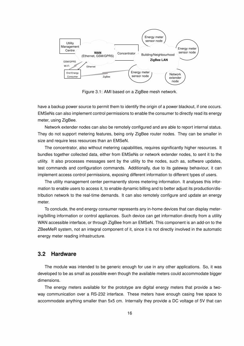
3.1 ZBeeMeR Architecture
Figure 3.1 presents the proposed AMR architecture and its components. Ethernet, GSM/GPRS,
Wi-Fi are shown as possible protocols to establish the communication between the WSN and the
utility. However, any other WAN protocol with adequate data rate and for the required distance can
be used.
EMSeNs are commercially available energy meters with a ZigBee module attached, that pro-
vides wireless capabilities to the meter. They are able to autonomously and independently re-
port measurement values, according to a pre-defined parametrisation, and to respond to external
requests. External requests can either be measurement requests, parameters configurations or
software updates. EMSeNs do not require great computational power. However, memory can be
an important issue, depending on the specifications of the time interval to maintain measured val-
ues. Under normal operation, they are powered by the electric grid. In spite of that, EMSeNs will
15
End Energy
Consumer
UtilityManagement
CentreConcentrator
Energy metersensor node
Energy metersensor node
Energy metersensor node Network
extendernode
ZigBee LAN
Building/NeighbourhoodWAN(Ethernet, GSM/GPRS)
Ethernet
GSM/GPRS
ZigBee
Wi-Fi
Figure 3.1: AMI based on a ZigBee mesh network.
have a backup power source to permit them to identify the origin of a power blackout, if one occurs.
EMSeNs can also implement control permissions to enable the consumer to directly read its energy
meter, using ZigBee.
Network extender nodes can also be remotely configured and are able to report internal status.
They do not support metering features, being only ZigBee router nodes. They can be smaller in
size and require less resources than an EMSeN.
The concentrator, also without metering capabilities, requires significantly higher resources. It
bundles together collected data, either from EMSeNs or network extender nodes, to sent it to the
utility. It also processes messages sent by the utility to the nodes, such as, software updates,
test commands and configuration commands. Additionally, due to its gateway behaviour, it can
implement access control permissions, exposing different information to different types of users.
The utility management center permanently stores metering information. It analyses this infor-
mation to enable users to access it, to enable dynamic billing and to better adjust its production/dis-
tribution network to the real-time demands. It can also remotely configure and update an energy
meter.
To conclude, the end energy consumer represents any in-home devices that can display meter-
ing/billing information or control appliances. Such device can get information directly from a utility
WAN accessible interface, or through ZigBee from an EMSeN. This component is an add-on to the
ZBeeMeR system, not an integral component of it, since it is not directly involved in the automatic
energy meter reading infrastructure.
3.2 Hardware
The module was intended to be generic enough for use in any other applications. So, it was
developed to be as small as possible even though the available meters could accommodate bigger
dimensions.
The energy meters available for the prototype are digital energy meters that provide a two-
way communication over a RS-232 interface. These meters have enough casing free space to
accommodate anything smaller than 5x5 cm. Internally they provide a DC voltage of 5V that can
16
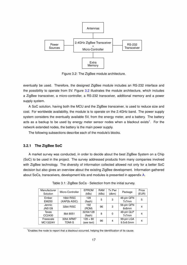
2.4GHz ZigBee Transceiver+
Micro-Controller
Antennas
PowerSources
RS-232Transceiver
ExtraMemory
Figure 3.2: The ZigBee module architecture.
eventually be used. Therefore, the designed ZigBee module includes an RS-232 interface and
the possibility to operate from 5V. Figure 3.2 illustrates the module architecture, which includes
a ZigBee transceiver, a micro-controller, a RS-232 transceiver, additional memory and a power
supply system.
A SoC solution, having both the MCU and the ZigBee transceiver, is used to reduce size and
cost. For worldwide availability, the module is to operate on the 2.4GHz band. The power supply
system considers the eventually available 5V, from the energy meter, and a battery. The battery
acts as a backup to be used by energy meter sensor nodes when a blackout exists1. For the
network extended nodes, the battery is the main power supply.
The following subsections describe each of the module’s blocks.
3.2.1 The ZigBee SoC
A market survey was conducted, in order to decide about the best ZigBee System on a Chip
(SoC) to be used in the project. The survey addressed products from many companies involved
with ZigBee technology. The diversity of information collected allowed not only for a better SoC
decision but also gives an overview about the existing ZigBee development. Information gathered
about SoCs, transceivers, development kits and modules is presented in appendix A.
Table 3.1: ZigBee SoCs - Selection from the initial survey.
ManufacturerMicro-Controller
EPROM RAM Tx PwrPackage
PriceSolution (kBs) (kBs) (dbm) (EUR)
Ember 16bit RISC 1285 3
48-pin QFN5
EM250 (XAP2b ASIC) (flash) 7x7mmJennic
32bit RISC192
96 356-pin QFN
4JN5139 (ROM) 8x8mmTexas
8bit 805132/64/128
8 048-pin QLP
4CC2430 (flash) 7x7mm
Freescale 32bit ARM7 128 + 8096 4
99-pin LGA4
MC13224V TDMI-S (see text) 9.5x9.5mm
1Enables the node to report that a blackout occurred, helping the identification of its cause.
17

The initial survey lead to a more detailed analysis of Ember, Jennic, Texas Instruments and
Freescale solutions that are better in terms of features and development support. This detailed
technical information is in table A.2 also in appendix A. Table 3.12 summarises the characteristics
of the four SoCs.
The four selected SoCs have dedicated hardware for MAC management, handling preamble
insertion, CRC-16 computation and checking over the MAC payload, and all CSMA/CA tasks.
That hardware also computes the Received Signal Strength Indicator (RSSI) and the Link Quality
Indicator (LQI). The integrated circuits also include an 128bit-AES encryption engine responsible
for data encryption/decryption. The Micro-controller Unit (MCU) characteristics were not a decisive
factor for the final choice, since the application is not very computationally demanding. Further-
more, the four SoCs employ different architectures and run at different clock speeds, making it
hard to assess the best overall performance. Available memory differs significantly, due to different
architectures.
Freescale solution [37] integrates the SoC itself, the balun and RF matching components, by-
pass capacitors and 128 kBs of SPI flash memory into a Land Grid Array (LGA) [38]. The SoC
features 80 kBs of ROM and 96 kBs of RAM. The ROM comes preloaded with the bootstrap code,
the UART and SPI drivers and a basic implementation of IEEE 802.15.4 MAC.3 The application
code must be and the ZigBee stack can optionally be stored in the SPI flash memory. However the
program code and data are always accessed from ROM or RAM. Upon boot, the flash memory is
mirrored into RAM, effectively limiting the application size to less than 96 kBs. That also makes the
available RAM for the ZigBee routing tables and application variables dependent on the application
size.
The Jennic SoC [39] has a similar memory architecture, the 192 kBs of ROM are intended to
host bootstrap code, drivers, the ZigBee stack, and the application code and data. The 96 kBs of
RAM are shared between program variables and code, since all code is accessed from RAM. If
more memory is required for software storage, an external SPI flash memory must be bought.4
Ember [40] and Texas Instruments (TI) [41] present a different approach with a typical MCU
with internal flash memory and RAM. The RAM is used for variables/tables only, while the internal
flash hosts both the application and the ZigBee stack up to the 128 kBs available.
To make a ZigBee network, a ZigBee stack is necessary. All manufacturers provide their own
stack in the form of binary libraries. TI, Jennic and Freescale implement the ZigBee specification.
These stacks are freely available for download, but Freescale limits the availability to a 90 day
trial version. Ember implements the ZigBee Pro specification, but its availability depends on the
purchase of a development kit.
To design the ZigBee module is also important to have access to a development kit that offers
ZigBee nodes and programming/debugging platforms. Jennic provides the cheapest development
kits. Their development software is a GNU-based tool-chain freely available for download. Ember
2Prices are for quantities above 1000 units. The price for TI CC2430 refers to the 128 kBs version.3But can be extended to also host the ZigBee stack and code to handle the Serial Peripheral Interface (SPI) flash
memory.4Which increases this solution’s cost.
18

has the most expensive kits based on the xIDE compiler. Freescale and TI kits have a medium cost
and rely on the IAR Systems’ software.
All four solutions (table 3.1) are good, but each has advantages and disadvantages. Ember has
the advantages of being the only with a ZigBee Pro stack implementation and having the highest
number of modules in its development kits. However, that makes it the costlier solution, having
no freely available stack and the lowest amount of RAM in its SoC. Freescale solution eases
development by bundling, in a single package, the SoC and several other required components,
achieving the highest transmission power. In spite of that, Freescale has a limited free availability
for its stack and a high cost for a development kit with enough modules for field testing. Also, its
MCU memory architecture makes it hard to assess the amount of RAM available for stack tables
and application data. Jennic has the cheapest development kits and the highest amount of internal
storage memory, powered by a 32bit RISC MCU. Its disadvantages are the less optimised code that
may be obtained from its GNU-based tool chain and suffering from the same memory architecture
as Freescale. Finally, Texas Instruments is the only with flexibility in terms of flash sizes, it has the
biggest amount of RAM and uses a compiler optimised for its SoC. On the other hand, has the
weakest MCU and its development kits have a medium cost (when compared to the others already
presented).
To conclude, the characteristics of the SoC itself, the features and cost of the development kits
and the ZigBee stack availability, were the main decision factors about which SoC to use. Although
considering Jennic solution to be the most powerful and therefore the best solution, TI, the second
best solution, was chosen due to existing prior knowledge about it.
3.2.2 Power System
The module is intended to, under normal circumstances, be powered by the 5V available in
the energy meter. However, this solution requires inner access to the energy meter which may not
be viable to the utility, since any change requires the energy meter to undergo certification. The
alternative is to power the module from the electric grid by using an AC/DC converter. Additionally,
as already referred, batteries are required.
Power from Voltage Regulator
Some components in the module require a supply voltage of 3V. Therefore, a DC/DC voltage
regulator is required. Initially a switching regulator was considered since their generally more ef-
ficient than linear regulators [42]. However, by analysing components consumption I estimated,
that even when the radio is transmitting and the other chips are fully working as well (worst case
scenario), the module will consume less than 65mA. For such a low consumption, a linear regulator
is more efficient than a switching regulator [43], even if has a light load mode5 [44]. In addition,
switching converters are much more complex than linear regulators and consequently more expen-
5Also known has power save mode. In this mode, the switching is temporarily stopped between voltage thresholds,to reduce losses due to unnecessary switching.
19

sive, their cost difference goes up to more than double, so a linear regulator was chosen for this
work.
Linear regulators are basically a series pass transistor that works as a variable resistor. It
dissipates the excess power in order to generate a constant output voltage, independent of load
current. Because linear regulators require a voltage drop between their input and output terminals,
the maximum output voltage they can produce is equal to their input voltage minus its voltage drop-
out. To generate around 3V from the available 5V, a Low Drop-Out (LDO) regulator was required.
The TLV1117 linear regulator from Texas Instruments was the cheapest regulator that fulfilled the
requirements. It converts 5V into about 2.8V by means of two resistors. The 2.8V voltage was
chosen because it stands well inside the input voltage range of all the chips and is a good value for
battery charging.
Power from Rechargeable Battery
Chemical batteries are the classical solution to power circuits when the electrical grid is not
available. More recently super-capacitors and energy harvesting is being considered as a possi-
ble alternative. Solar energy [45], combined solar and wind energy [46] and RF harvesting [47]
are examples. Other forms are also exploited but no system is yet able to power a WSN node
continuously [48]. So, rechargeable chemical batteries were used.
There are many types of electrochemical cells, but Li-ion and Ni-MH stand out in terms of
energy density and size [49]. Li-ion batteries are less available to the general public than Ni-MH
and require a more complex charging circuit (see appendix B). Therefore, Ni-MH batteries were
chosen.
Voltageregulator
Rechargeablebatteries
ZigBee Modulepower feed
points
V+
V-
Figure 3.3: ZigBee module’s power supply diagram.
Two AA Ni-MH rechargeable batteries in series are required to produce a voltage inside the
chips range. To guarantee uninterrupted operation, both the battery pack and the linear regulator
are connected in parallel feeding the module simultaneously (see figure 3.3). This simple arrange-
ment saves the cost and space of a solution involving power sensing and switching, while ensuring
that the module will only stop working if both power sources are not present.
The charging circuit used is very simple and may shorten batteries lifetime (see appendix B).
We considered that a more expensive and complex charging circuit is not justified due to its seldom
use. The low outage occurrence and low power drained by the module means the batteries will be
fully charged over the majority of their lifetime.
As Ni-MH batteries shall be charged with a fixed current method, the simple charging circuit
devised only required one resistor (see figure 3.4). Due to the resistor, charging is done with
20

Voltageregulator
2.8V 2.0V to 2.8V
C1C2
R
2 AABatteries
Figure 3.4: Battery charging circuit.
a very low current and stops naturally when the batteries voltage reaches the 2.8V imposed by
the linear regulator. This 2.8V threshold voltage was chosen after careful study of charge dia-
grams of different Ni-MH battery manufacturers. As the batteries are assumed to be at full capacity
for the majority of time, this charging occurs in an intermittent manner6, that according to some
manufacturers [50, p. 13], improves charge efficiency, extends battery life and reduces electricity
consumption when compared to a low rate continuous charge method.
3.2.3 Antennas
The module needs an antenna for 2.4GHz. Three possible alternatives for the antenna exist.
The antenna can be printed on the Printed Circuit Board (PCB), can be inside a chip (chip antenna)
or be a whip antenna. In [51], Texas Instruments presents a good overview about that alternatives.
Table 3.2 summarises the advantages and disadvantages of the three types of antennas. Based on
Table 3.2: Comparison of Antenna Solutions.
Antenna Advantages Disadvantagestypes
• Low cost • Hard to designPCB • Good performance • Big at low frequencies
antenna • Small at high frequencies • Non-steerable• Standard designs widely available
Chip • Compact size • Medium performanceantenna • Short time to market • Medium cost
Whip • Good performance • High costantenna • Short time to market • Difficult to fit in some applications
table 3.2 it is possible to conclude that chip antennas are an average option. They are smaller but
more expensive and have lower performance than PCB antennas. Therefore, we decided to use a
PCB antenna and also a whip antenna. Both alternatives cannot be used simultaneously though,
switching between them requires the unsolder and re-solder of a capacitor. Implementing these two
alternatives will provide the possibility to analyse and compare them for a future implementation.
PCB and whip alternatives were considered has they can share the same balun7. By contrast, the
6This intermittent charging mechanism is similar to the maintenance Ni-MH battery charging stage, referred on ap-pendix B.
7The balun converts the single ended 50 ohm feed point of the antenna to the differential antenna interface of theZigBee SoC.
21

chip antenna requires a different balun [52].
Texas Instruments suggests the use of Folded Dipoles [53], Inverted F antennas [54] or Mean-
dered Inverted F antennas [55] to implement PCB antennas for the 2.4GHz band. They provide
information describing the antenna, explaining how to design it and providing results from perfor-
mance tests. We choose the Inverted F antenna, since it achieves the best trade off between
size and performance. The balun was implemented with a microstrip balun and only 4 discrete
components following the design proposed by Texas Instruments.
As the ZigBee module will be located inside the electric meter casing, and the whip antenna
will be in the outside for better signal reception, the whip antenna is supported by a small U.FL
connector8 in the PCB. At first a Micro-miniature Coaxial (MMCX) vertical mounted connector was
chosen due to its little size and robustness, but at purchase time it was unavailable, so it was
replaced by the U.FL connector. The U.FL connector is smaller, but less robust than the MMCX.
However, as the antenna will be attached to the meter casing little stress is applied to the connector.
3.2.4 Serial Communication and Extra Memory
The ZigBee SoC provides two UART controllers that output signals at the TTL levels. Maxim
Max3319 is the integrated circuit chosen to convert between TTL and RS-232 voltage levels, due to
its ability to operate under low voltage levels− 2, 25V to 3, 00V − and to automatically be shutdown
and reactivated. It shutdowns after 30 seconds without communication activity and reactivates itself
upon receiving a valid RS-232 level signal, avoiding the use of Input/Output (I/O) ports of the ZigBee
SoC to control the TTL/RS-232 conversion.
Additional memory is included in the ZigBee module, to make possible to store energy mea-
surements over a considerable amount of time. We choose a SPI enabled flash memory. There are
no special requirements nor speed constraints, so cost and upgrade possibility9 were the decision
factors. Therefore, the Numonyx M25P40, a low voltage 512 kBs flash memory was selected.
3.2.5 Printed Circuit Board
The circuit was designed using OrCad 10.3 software. Footprints from OrCad’s libraries or
designed according to data-sheets were used. On both cases, pads were incremented by 10%
in average to provide a bigger tolerance to misplacements that may occur when components are
assembled. All used components are of Surface Mounted Device (SMD) type, to ensure a small
sized module.
The circuit was implemented in a 4-layer PCB (figure 3.5) with 1 millimetre thickness, due to
TI’s specification for its microstrip balun [54]. The two outer layers are used for signal routing and
the two inner layers for ground and power planes. Components are mounted on the upper layer
and the ground plane is the layer immediately below.
8U.FL is a miniature coaxial RF connector for high-frequency signals up to 6GHz manufactured by Hirose ElectricGroup in Japan. It is part of the ultra small surface mount coaxial connectors.
9In terms of having other, pin-compatible, flash memory sizes.
22

Copper - Top Routing Layer
Copper - Ground Layer
Copper - Power Layer
Copper - Bottom Routing Layer
Prepreg: Uncured Fiberglass-Epoxy Resin
Prepreg: Uncured Fiberglass-Epoxy Resin
Core: Cured Fiberglass-Epoxy Resin
Figure 3.5: Layer stack-up on a 4-layer PCB.
Loop inductance can be a problem on PCBs that handle high frequency signals [56]. Power
and ground planes reduce loop inductance by allowing a return path to exist near the signal path.
A plane has also less inductance than a narrow trace, which further reduces path inductance.
Furthermore, stacking the ground plane in a inner plane, provides isolation between the signals
routed on the outer layers. While the power plane makes the Direct Current (DC) voltage available
near any component pin by means of a short trace. So, planes also make it possible to reduce the
PCB size, through trace length reduction.
To further preserve signal integrity and ensure a stable power supply, the layout was designed
taking into account the following issues:
- The fast switching of digital circuits is usually a source of noise that causes unwanted inter-ference, specially on analog signals. Therefore, to minimise interference within the PCB, theRadio Frequency (RF) section is placed on the opposite corner to the digital components andpower supply (figure 3.6).
Figure 3.6: Digital and analog separation on the PCB.
- The empty spaces (not populated with traces) on the routing layers are also flooded withcopper connected to ground for additional signal isolation.
- All traces across the PCB are keep as small as possible to reduce their inductance.
- Traces that cannot go in a straight line are chamfered ( 45◦ ) to reduce their capacitance.
- Bypass capacitors are used to improve power distribution. They short circuit high frequencynoise and serve as charge reservoirs. Bypass capacitors are mounted as close as possible
23
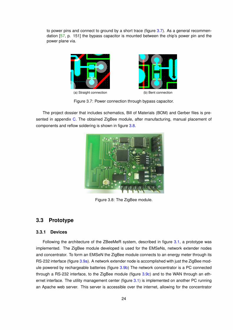
to power pins and connect to ground by a short trace (figure 3.7). As a general recommen-dation [57, p. 151] the bypass capacitor is mounted between the chip’s power pin and thepower plane via.
(a) Straight connection (b) Bent connection
Figure 3.7: Power connection through bypass capacitor.
The project dossier that includes schematics, Bill of Materials (BOM) and Gerber files is pre-
sented in appendix C. The obtained ZigBee module, after manufacturing, manual placement of
components and reflow soldering is shown in figure 3.8.
Figure 3.8: The ZigBee module.
3.3 Prototype
3.3.1 Devices
Following the architecture of the ZBeeMeR system, described in figure 3.1, a prototype was
implemented. The ZigBee module developed is used for the EMSeNs, network extender nodes
and concentrator. To form an EMSeN the ZigBee module connects to an energy meter through its
RS-232 interface (figure 3.9a). A network extender node is accomplished with just the ZigBee mod-
ule powered by rechargeable batteries (figure 3.9b) The network concentrator is a PC connected
through a RS-232 interface, to the ZigBee module (figure 3.9c) and to the WAN through an eth-
ernet interface. The utility management center (figure 3.1) is implemented on another PC running
an Apache web server. This server is accessible over the internet, allowing for the concentrator
24
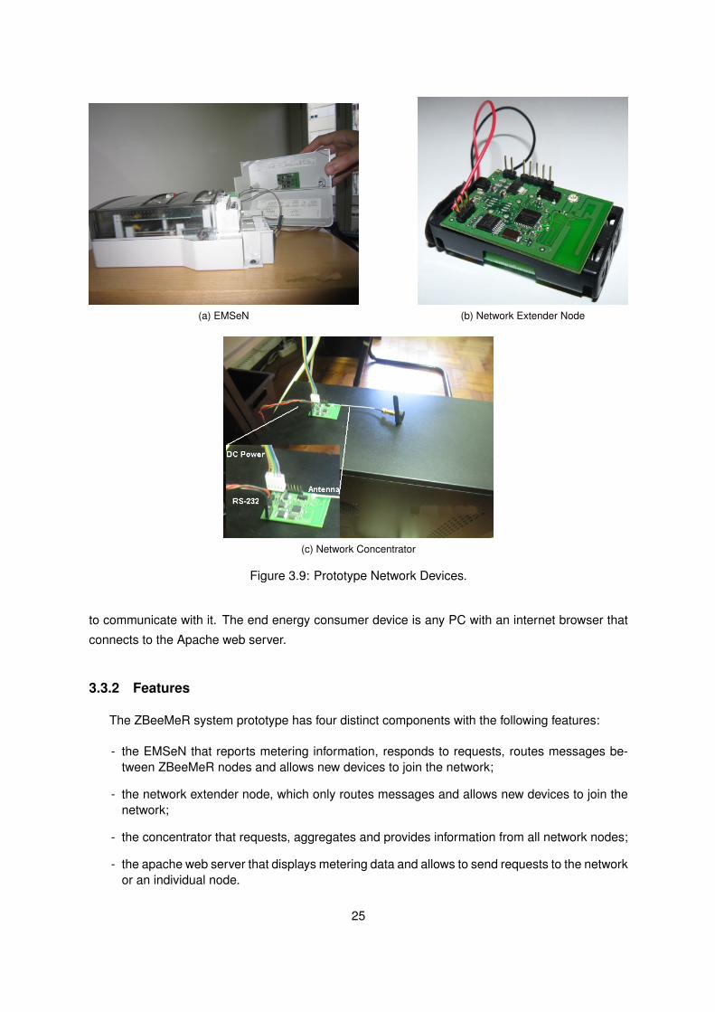
(a) EMSeN (b) Network Extender Node
(c) Network Concentrator
Figure 3.9: Prototype Network Devices.
to communicate with it. The end energy consumer device is any PC with an internet browser that
connects to the Apache web server.
3.3.2 Features
The ZBeeMeR system prototype has four distinct components with the following features:
- the EMSeN that reports metering information, responds to requests, routes messages be-tween ZBeeMeR nodes and allows new devices to join the network;
- the network extender node, which only routes messages and allows new devices to join thenetwork;
- the concentrator that requests, aggregates and provides information from all network nodes;
- the apache web server that displays metering data and allows to send requests to the networkor an individual node.
25
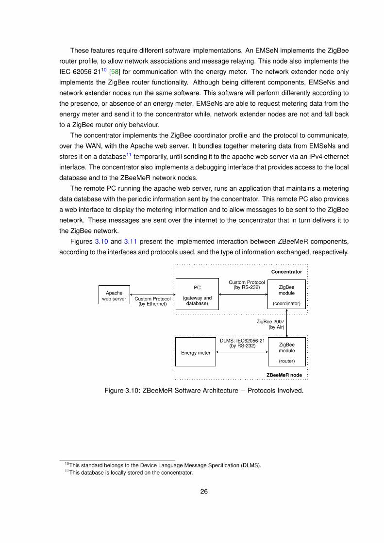
These features require different software implementations. An EMSeN implements the ZigBee
router profile, to allow network associations and message relaying. This node also implements the
IEC 62056-2110 [58] for communication with the energy meter. The network extender node only
implements the ZigBee router functionality. Although being different components, EMSeNs and
network extender nodes run the same software. This software will perform differently according to
the presence, or absence of an energy meter. EMSeNs are able to request metering data from the
energy meter and send it to the concentrator while, network extender nodes are not and fall back
to a ZigBee router only behaviour.
The concentrator implements the ZigBee coordinator profile and the protocol to communicate,
over the WAN, with the Apache web server. It bundles together metering data from EMSeNs and
stores it on a database11 temporarily, until sending it to the apache web server via an IPv4 ethernet
interface. The concentrator also implements a debugging interface that provides access to the local
database and to the ZBeeMeR network nodes.
The remote PC running the apache web server, runs an application that maintains a metering
data database with the periodic information sent by the concentrator. This remote PC also provides
a web interface to display the metering information and to allow messages to be sent to the ZigBee
network. These messages are sent over the internet to the concentrator that in turn delivers it to
the ZigBee network.
Figures 3.10 and 3.11 present the implemented interaction between ZBeeMeR components,
according to the interfaces and protocols used, and the type of information exchanged, respectively.
Concentrator
Apacheweb server
PC
(gateway anddatabase)
ZigBeemodule
(coordinator)Custom Protocol
(by Ethernet)
Custom Protocol(by RS-232)
ZigBee 2007(by Air)
ZBeeMeR node
ZigBeemodule
(router)
Energy meter
DLMS: IEC62056-21(by RS-232)
Figure 3.10: ZBeeMeR Software Architecture − Protocols Involved.
10This standard belongs to the Device Language Message Specification (DLMS).11This database is locally stored on the concentrator.
26
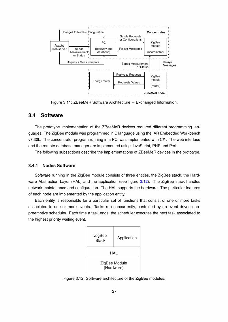
Concentrator
Apacheweb server
PC
(gateway anddatabase)
ZigBeemodule
(coordinator)Sends
Measurementor Status
Relays Messages
Sends Requestsor Configurations
RelaysMessagesSends Measurement
or Status
ZBeeMeR node
ZigBeemodule
(router)
Energy meter Requests Values
Replys to Requests
Changes to Nodes Configuration
Requests Measurements
Figure 3.11: ZBeeMeR Software Architecture − Exchanged Information.
3.4 Software
The prototype implementation of the ZBeeMeR devices required different programming lan-
guages. The ZigBee module was programmed in C language using the IAR Embedded Workbench
v7.30b. The concentrator program running in a PC, was implemented with C# . The web interface
and the remote database manager are implemented using JavaScript, PHP and Perl.
The following subsections describe the implementations of ZBeeMeR devices in the prototype.
3.4.1 Nodes Software
Software running in the ZigBee module consists of three entities, the ZigBee stack, the Hard-
ware Abstraction Layer (HAL) and the application (see figure 3.12). The ZigBee stack handles
network maintenance and configuration. The HAL supports the hardware. The particular features
of each node are implemented by the application entity.
Each entity is responsible for a particular set of functions that consist of one or more tasks
associated to one or more events. Tasks run concurrently, controlled by an event driven non-
preemptive scheduler. Each time a task ends, the scheduler executes the next task associated to
the highest priority waiting event.
ApplicationZigBeeStack
HAL
ZigBee Module(Hardware)
Figure 3.12: Software architecture of the ZigBee modules.
27
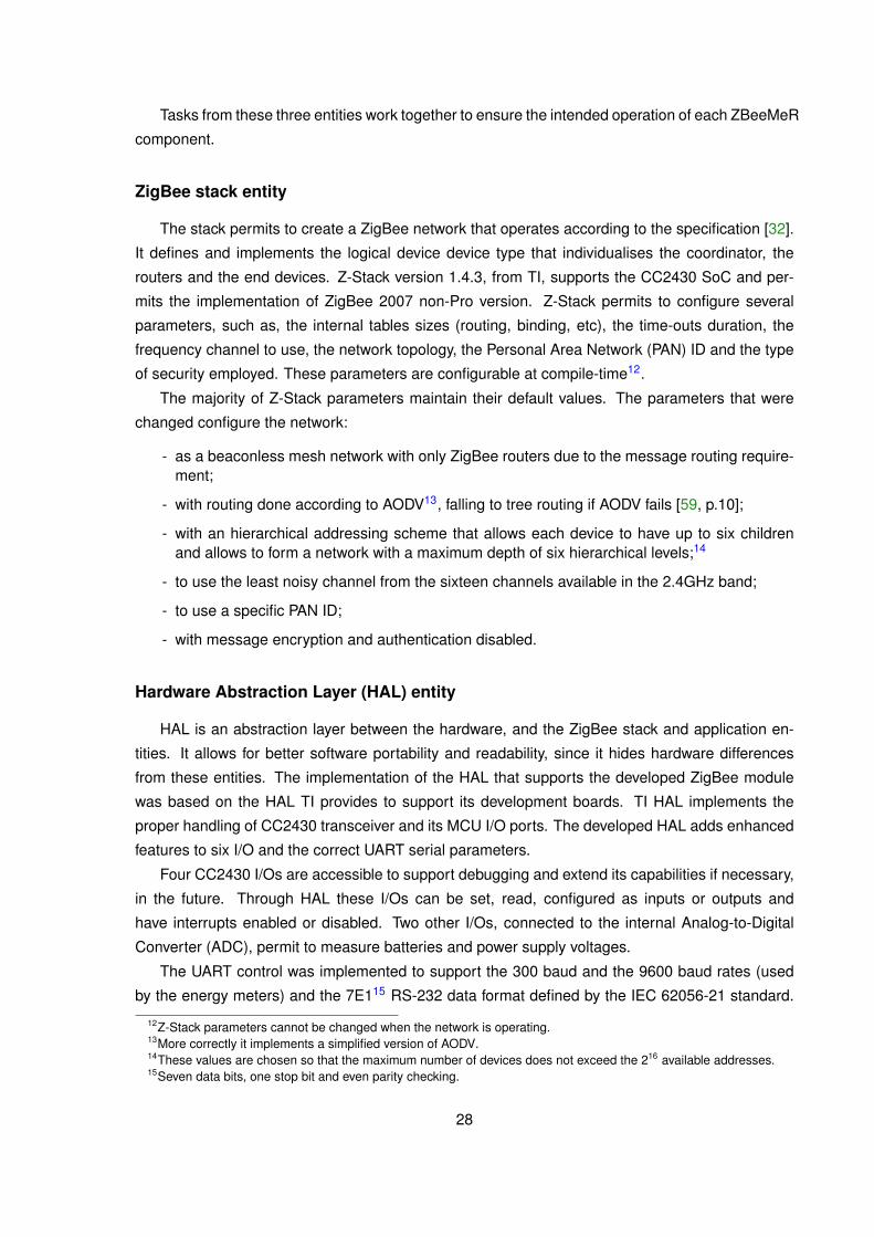
Tasks from these three entities work together to ensure the intended operation of each ZBeeMeR
component.
ZigBee stack entity
The stack permits to create a ZigBee network that operates according to the specification [32].
It defines and implements the logical device device type that individualises the coordinator, the
routers and the end devices. Z-Stack version 1.4.3, from TI, supports the CC2430 SoC and per-
mits the implementation of ZigBee 2007 non-Pro version. Z-Stack permits to configure several
parameters, such as, the internal tables sizes (routing, binding, etc), the time-outs duration, the
frequency channel to use, the network topology, the Personal Area Network (PAN) ID and the type
of security employed. These parameters are configurable at compile-time12.
The majority of Z-Stack parameters maintain their default values. The parameters that were
changed configure the network:
- as a beaconless mesh network with only ZigBee routers due to the message routing require-ment;
- with routing done according to AODV13, falling to tree routing if AODV fails [59, p.10];
- with an hierarchical addressing scheme that allows each device to have up to six childrenand allows to form a network with a maximum depth of six hierarchical levels;14
- to use the least noisy channel from the sixteen channels available in the 2.4GHz band;
- to use a specific PAN ID;
- with message encryption and authentication disabled.
Hardware Abstraction Layer (HAL) entity
HAL is an abstraction layer between the hardware, and the ZigBee stack and application en-
tities. It allows for better software portability and readability, since it hides hardware differences
from these entities. The implementation of the HAL that supports the developed ZigBee module
was based on the HAL TI provides to support its development boards. TI HAL implements the
proper handling of CC2430 transceiver and its MCU I/O ports. The developed HAL adds enhanced
features to six I/O and the correct UART serial parameters.
Four CC2430 I/Os are accessible to support debugging and extend its capabilities if necessary,
in the future. Through HAL these I/Os can be set, read, configured as inputs or outputs and
have interrupts enabled or disabled. Two other I/Os, connected to the internal Analog-to-Digital
Converter (ADC), permit to measure batteries and power supply voltages.
The UART control was implemented to support the 300 baud and the 9600 baud rates (used
by the energy meters) and the 7E115 RS-232 data format defined by the IEC 62056-21 standard.
12Z-Stack parameters cannot be changed when the network is operating.13More correctly it implements a simplified version of AODV.14These values are chosen so that the maximum number of devices does not exceed the 216 available addresses.15Seven data bits, one stop bit and even parity checking.
28

As the UART in the CC2430 only supports RS-232 formats with eight and nine data bits, two
algorithms were defined in HAL to convert serial data. These algorithms operate on the basis that
a 7E1 format has the same number of bits has an 8N116, therefore the UART is configured to use
the 8N1 data format and HAL converts data to the required 7E1.
3.4.2 EMSeNs and Network Extender Nodes
As already referred (subsection 3.3.2), EMSeNs and network extender nodes run the same
software inside CC2430 MCU. Their specific behaviour is defined by the ability to communicate with
an energy meter. The program flowchart of these two ZBeeMeR nodes is illustrated on figure 3.13.
Each node starts by initialising variables and registering for network and/or HAL notifications.
Then, the node searches for the pre-programmed PAN ID in all available channels. If the joining
process is unsuccessful, it retries several times before permanently aborting the joining process,
stopping its execution. However, when the joining process is successful, the node joins the ZigBee
network and attempts to communicate with the energy meter, requesting its serial number. If the
communication fails, the node immediately informs the concentrator about the failure, although it
retries a number of times. After the maximum number of retries is reached, it defaults to a network
extender node, informing the concentrator of such decision. If the meter serial number is obtained
the node defaults to an EMSeN, informing the concentrator of its association with the energy meter.
Then, the code running in a node enters a loop, waiting for events to be processed.
The program flowchart (figure 3.13) only shows the two main application events. Other events
include:
- ZigBee stack messages that inform17 the application about changes in the network status,about new devices that joined the network or about any particular request or response per-taining device and/or service discovery.
- HAL notifications to inform the application when the power supply is turned off, when thebatteries are running low, when one of the accessible I/Os has been triggered or when atimer expires. Timer notifications control the reading periodicity of energy measurements,time-outs and retrying delays.
- Signals to break large execution threads, allowing another tasks to run. This is advised dueto the non-preemptive nature of the scheduler.
- ZBeeMeR data or configuration request messages sent by the concentrator. Data requestsare used to ask for metering information in real time. Configuration requests permit to:
◦ set the periodicity of autonomous measurements reading;◦ set meter login information;◦ obtain unique identifiers from ZigBee module and form energy meter;
For each message exchange (request or response) between a node and the concentrator, the is
an ACK. If the ACK is not received, the sender device resends the message for a defined number
16Eight data bits and one stop bit without parity checking.17The application is only informed of the events it registered for, in the initialization phase.
29
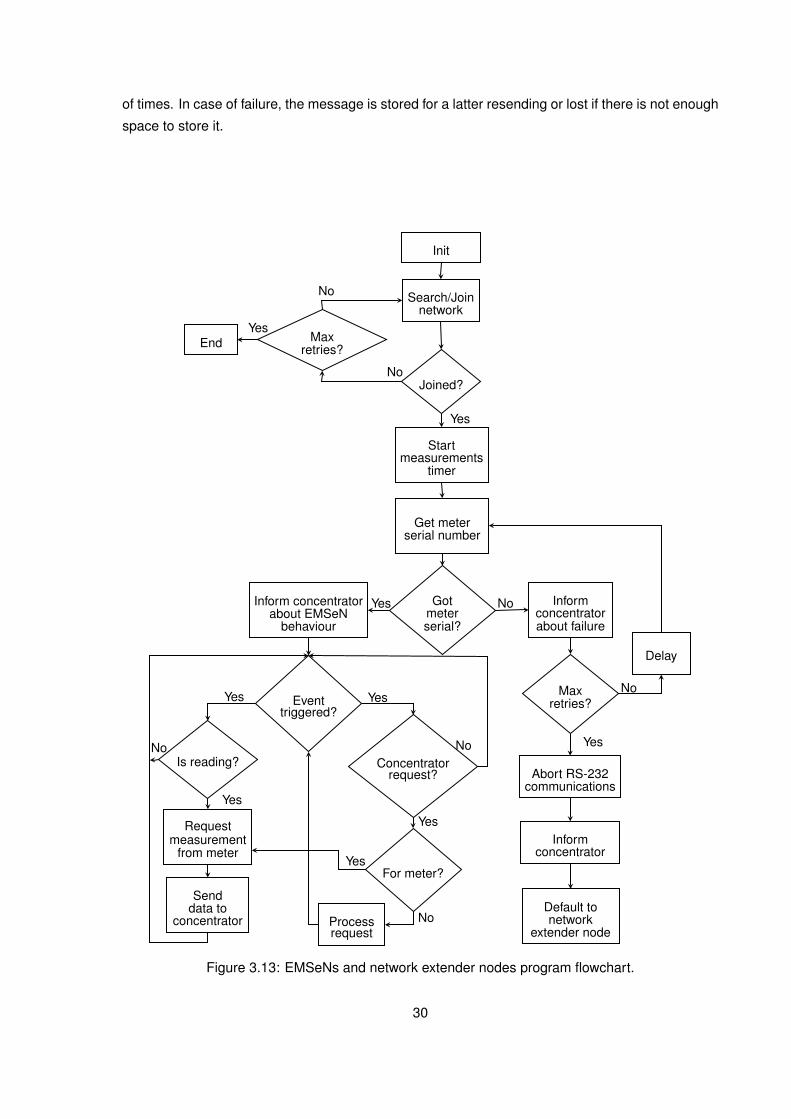
of times. In case of failure, the message is stored for a latter resending or lost if there is not enough
space to store it.
Init
Search/Joinnetwork
Startmeasurements
timer
Get meterserial number
Default tonetwork
extender node
Abort RS-232communications
Delay
Informconcentratorabout failure
Informconcentrator
Requestmeasurement
from meter
Processrequest
Senddata to
concentrator
Inform concentratorabout EMSeN
behaviour
End
Joined?
Maxretries?
Gotmeterserial?
Eventtriggered?
Is reading? Concentratorrequest?
For meter?
Maxretries?
No
Yes
No
Yes
NoYes
No
Yes
Yes Yes
No
Yes
No
Yes
Yes
No
Figure 3.13: EMSeNs and network extender nodes program flowchart.
30
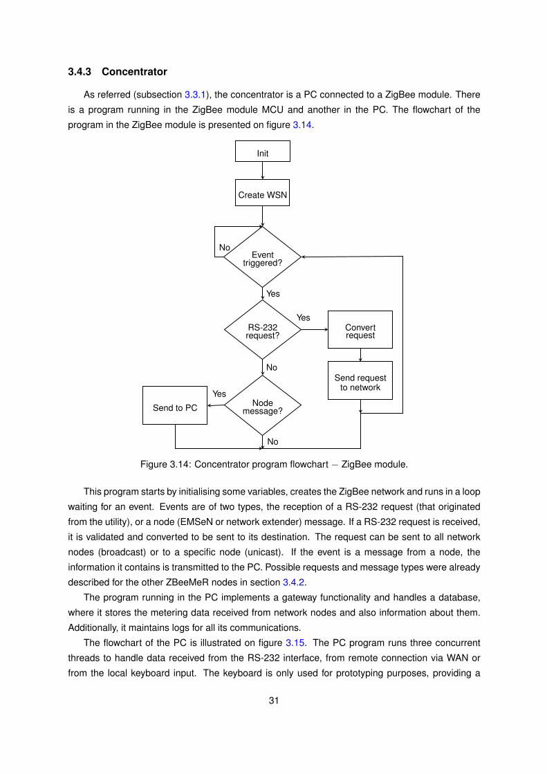
3.4.3 Concentrator
As referred (subsection 3.3.1), the concentrator is a PC connected to a ZigBee module. There
is a program running in the ZigBee module MCU and another in the PC. The flowchart of the
program in the ZigBee module is presented on figure 3.14.
Init
Send requestto network
Eventtriggered?
Yes
Create WSN
RS-232request?
Nodemessage?
Convertrequest
Send to PC
No
Yes
Yes
No
No
Figure 3.14: Concentrator program flowchart − ZigBee module.
This program starts by initialising some variables, creates the ZigBee network and runs in a loop
waiting for an event. Events are of two types, the reception of a RS-232 request (that originated
from the utility), or a node (EMSeN or network extender) message. If a RS-232 request is received,
it is validated and converted to be sent to its destination. The request can be sent to all network
nodes (broadcast) or to a specific node (unicast). If the event is a message from a node, the
information it contains is transmitted to the PC. Possible requests and message types were already
described for the other ZBeeMeR nodes in section 3.4.2.
The program running in the PC implements a gateway functionality and handles a database,
where it stores the metering data received from network nodes and also information about them.
Additionally, it maintains logs for all its communications.
The flowchart of the PC is illustrated on figure 3.15. The PC program runs three concurrent
threads to handle data received from the RS-232 interface, from remote connection via WAN or
from the local keyboard input. The keyboard is only used for prototyping purposes, providing a
31
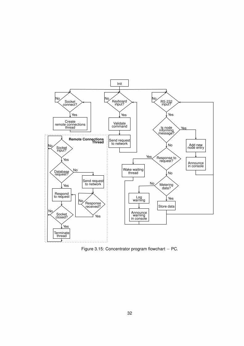
Remote ConnectionsThread
Init
Validatecommand
Send requestto network
Wake waitingthread
Add newnode entry
Terminatethread
Logwarning
Respondto request
Createremote connections
thread
Keyboardinput?
Is nodeinformingmessage?
Meteringdata?
Responsereceived?
Socketclosed?
Response torequest?
Databaserequest?
Yes
NoNo
Yes
No
No
No
Yes
Yes
No
No
Yes
Yes
YesNo
Socketconnect?
RS-232input?
Announcein console
Store data
Announcewarning
in console
Socketinput?
Send requestto network
YesYes Yes
No No
Figure 3.15: Concentrator program flowchart − PC.
32
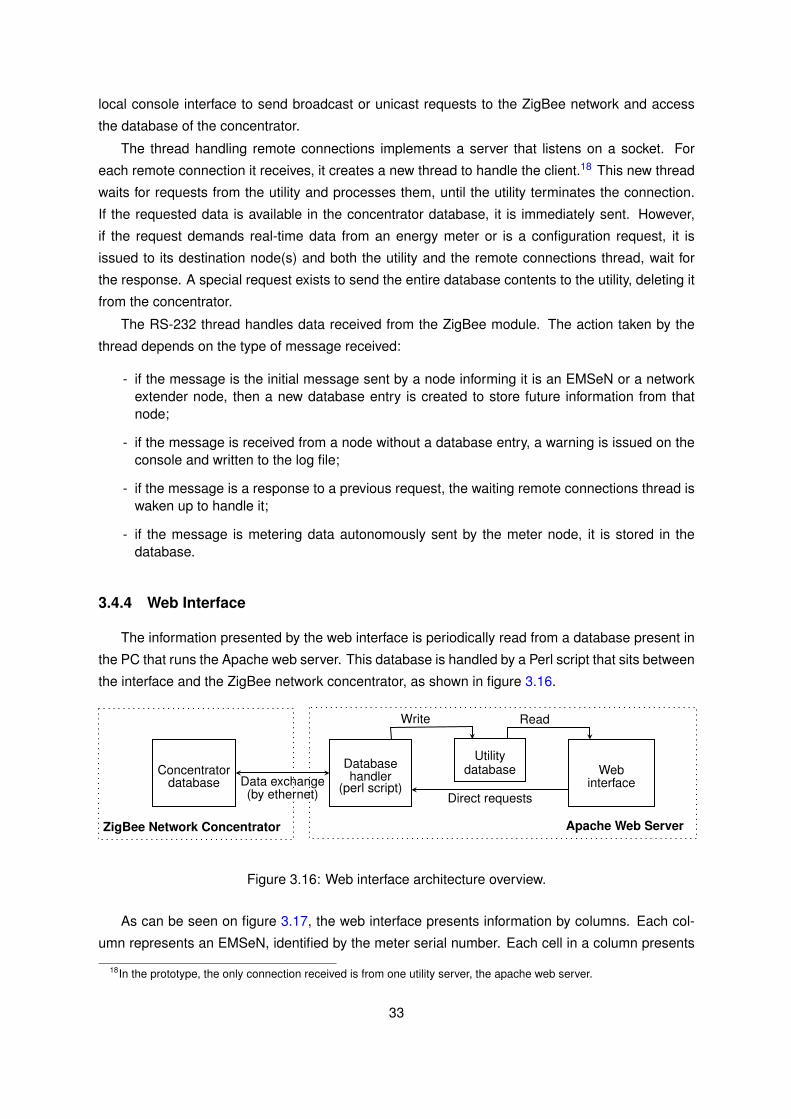
local console interface to send broadcast or unicast requests to the ZigBee network and access
the database of the concentrator.
The thread handling remote connections implements a server that listens on a socket. For
each remote connection it receives, it creates a new thread to handle the client.18 This new thread
waits for requests from the utility and processes them, until the utility terminates the connection.
If the requested data is available in the concentrator database, it is immediately sent. However,
if the request demands real-time data from an energy meter or is a configuration request, it is
issued to its destination node(s) and both the utility and the remote connections thread, wait for
the response. A special request exists to send the entire database contents to the utility, deleting it
from the concentrator.
The RS-232 thread handles data received from the ZigBee module. The action taken by the
thread depends on the type of message received:
- if the message is the initial message sent by a node informing it is an EMSeN or a networkextender node, then a new database entry is created to store future information from thatnode;
- if the message is received from a node without a database entry, a warning is issued on theconsole and written to the log file;
- if the message is a response to a previous request, the waiting remote connections thread iswaken up to handle it;
- if the message is metering data autonomously sent by the meter node, it is stored in thedatabase.
3.4.4 Web Interface
The information presented by the web interface is periodically read from a database present in
the PC that runs the Apache web server. This database is handled by a Perl script that sits between
the interface and the ZigBee network concentrator, as shown in figure 3.16.
ZigBee Network Concentrator Apache Web Server
Concentratordatabase
Databasehandler
(perl script)Web
interface
Utilitydatabase
Direct requests
Write Read
Data exchange(by ethernet)
Figure 3.16: Web interface architecture overview.
As can be seen on figure 3.17, the web interface presents information by columns. Each col-
umn represents an EMSeN, identified by the meter serial number. Each cell in a column presents
18In the prototype, the only connection received is from one utility server, the apache web server.
33
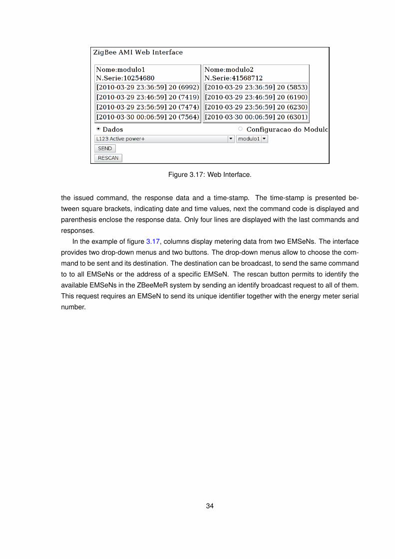
Figure 3.17: Web Interface.
the issued command, the response data and a time-stamp. The time-stamp is presented be-
tween square brackets, indicating date and time values, next the command code is displayed and
parenthesis enclose the response data. Only four lines are displayed with the last commands and
responses.
In the example of figure 3.17, columns display metering data from two EMSeNs. The interface
provides two drop-down menus and two buttons. The drop-down menus allow to choose the com-
mand to be sent and its destination. The destination can be broadcast, to send the same command
to to all EMSeNs or the address of a specific EMSeN. The rescan button permits to identify the
available EMSeNs in the ZBeeMeR system by sending an identify broadcast request to all of them.
This request requires an EMSeN to send its unique identifier together with the energy meter serial
number.
34

Chapter 4
Tests and Results
Several tests were performed to test the ZBeeMeR system functionality, the electrical correct-
ness of the ZigBee module, and the power emissions compliance with the IEEE 802.15.4 standard
and ranges achieved.
4.1 Module Tests
After soldering the received manufactured PCB panel, by applying solder paste, using a sten-
cil sheet, and manually placing components, some electrical tests were performed. These tests
ensured the absence of short circuits in-between layers and chips pins, and confirmed the power
levels throughout the board.
Radio emissions were verified using a Rohde & Schwarz FS300 spectrum analyser to:
1. test for the existence of emissions out of band the 2.4GHz band;
2. test for compliance with the maximum channel center frequency deviation allowed;
3. test for compliance with the maximum channel bandwidth allowed.
Due to missing equipment for measuring power emissions from the antenna implemented on the
PCB, only the external whip antenna was used for the tests. However, since they use the same
balun results can be extrapolated.
Figure 4.1 shows power emissions for four channels over a 3GHz frequency span. Based on
that, we can conclude that all frequencies are in the 2.4GHz and no spurious emissions exist.
35
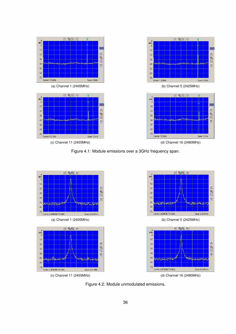
(a) Channel 1 (2405MHz) (b) Channel 5 (2425MHz)
(c) Channel 11 (2455MHz) (d) Channel 16 (2480MHz)
Figure 4.1: Module emissions over a 3GHz frequency span.
(a) Channel 1 (2405MHz) (b) Channel 5 (2425MHz)
(c) Channel 11 (2455MHz) (d) Channel 16 (2480MHz)
Figure 4.2: Module unmodulated emissions.
36

Figure 4.2 shows, in detail, the center frequency of the four channels. Table 4.1 presents the
frequency deviation for all sixteen channels. All channels have a deviation of 404Hz. As according
to the IEEE 802.15.4 standard, the maximum allowed tolerance is 100Hz, further RF tuning is
required.
Table 4.1: Deviations from the centre channel frequency.
Channel Teorical Measured DeviationNumber (GHz) (GHz) (Hz)
1 2.4050 2.404596 4042 2.4100 2.409596 4043 2.4150 2.414596 4044 2.4200 2.419596 4045 2.4250 2.424596 4046 2.4300 2.429596 4047 2.4350 2.434596 4048 2.4400 2.439596 4049 2.4450 2.444596 40410 2.4500 2.449596 40411 2.4550 2.454596 40412 2.4600 2.459596 40413 2.4650 2.464596 40414 2.4700 2.469596 40415 2.4750 2.474596 40416 2.4800 2.479596 404
37
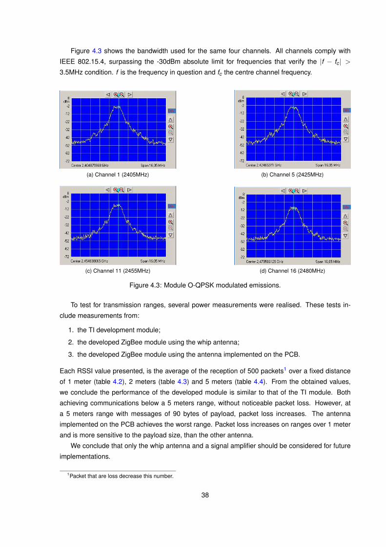
Figure 4.3 shows the bandwidth used for the same four channels. All channels comply with
IEEE 802.15.4, surpassing the -30dBm absolute limit for frequencies that verify the |f − fc| >3.5MHz condition. f is the frequency in question and fc the centre channel frequency.
(a) Channel 1 (2405MHz) (b) Channel 5 (2425MHz)
(c) Channel 11 (2455MHz) (d) Channel 16 (2480MHz)
Figure 4.3: Module O-QPSK modulated emissions.
To test for transmission ranges, several power measurements were realised. These tests in-
clude measurements from:
1. the TI development module;
2. the developed ZigBee module using the whip antenna;
3. the developed ZigBee module using the antenna implemented on the PCB.
Each RSSI value presented, is the average of the reception of 500 packets1 over a fixed distance
of 1 meter (table 4.2), 2 meters (table 4.3) and 5 meters (table 4.4). From the obtained values,
we conclude the performance of the developed module is similar to that of the TI module. Both
achieving communications below a 5 meters range, without noticeable packet loss. However, at
a 5 meters range with messages of 90 bytes of payload, packet loss increases. The antenna
implemented on the PCB achieves the worst range. Packet loss increases on ranges over 1 meter
and is more sensitive to the payload size, than the other antenna.
We conclude that only the whip antenna and a signal amplifier should be considered for future
implementations.
1Packet that are loss decrease this number.
38

Table 4.2: Power measurements over a 1 meter distance.
Antenna Average Lost Error Average Lost ErrorType RSSI (dBm) Packets (% ) RSSI (dBm) Packets (% )
30bytes of payload 90bytes of payload-43,4 0 0,0 -43,8 0 0,0
Whip (TI) -40,7 0 0,0 -42,8 0 0,0-43,9 0 0,0 -43,1 0 0,0-31,7 0 0,0 -31,6 0 0,0
Whip -31,4 1 0,2 -31,8 0 0,0-32,1 0 0,0 -31,7 0 0,0-42,1 0 0,0 -42,1 0 0,0
PCB -42,1 0 0,0 -42,1 0 0,0-42,1 1 0,2 -42,1 0 0,0
Table 4.3: Power measurements over a 2 meters distance.
Antenna Average Lost Error Average Lost ErrorType RSSI (dBm) Packets (% ) RSSI (dBm) Packets (% )
30bytes of payload 90bytes of payload-53,9 0 0,0 -57,4 1 0,2
Whip (TI) -54,9 1 0,2 -57,7 1 0,2-57,2 0 0,0 -58,2 1 0,2-45,4 0 0,0 -45,6 0 0,0
Whip -45,9 0 0,0 -45,8 0 0,0-45,4 0 0,0 -45,2 0 0,0-65,6 46 9,2 -66,2 95 19,0
PCB -65,2 85 17,0 -65,8 136 27,2-64,4 79 15,8 -65,8 130 26,0
Table 4.4: Power measurements over a 5 meters distance.
Antenna Average Lost Error Average Lost ErrorType RSSI (dBm) Packets (% ) RSSI (dBm) Packets (% )
30bytes of payload 90bytes of payload-57,2 1 0,2 64,5 4 0,8
Whip (TI) -63,8 4 0,8 61,5 6 1,2-56,8 1 0,2 65,8 6 1,2-63,1 5 1,0 61,6 15 3,0
Whip -61,2 3 0,6 66,1 25 5,0-62,5 9 1,8 59,8 36 7,2
39

4.2 ZBeeMeR Tests
To validate the network functionality, the message routing, the possibility to increase coverage
with network extender nodes, and the adequacy of ZigBee for AMI, the ZBeeMeR system was
set-up. It consisted of a network with four nodes distributed on a building floor, as presented on
figure 4.42. The network includes two EMSeNs, a network extender node and the concentrator.
The network extender node, situated in the corridor, assures that the data from EMSeN 1 arrives
at the concentrator.
Figure 4.4: Prototype network structure with nodes location.
The first three tests permit to validate the network configuration, and the last three the function-
ality. Appendix D presents the packets exchanged between the four nodes. For testing purposes,
the web interface is used to send requests and to display metering values. The metering values
returned from requests sent to the EMSeN were confirmed by the energy meter LCD display.
Test 1. Activation of the concentrator and EMSeN 1: no network association occurred because theyare out of range.
Test 2. Introduction of a network extender node: metering data from EMSeN 1 arrived at the con-centrator.
Test 3. Activation of EMSeN 2: metering data arrived at the concentrator.
Test 4. Metering data requested to all nodes (using a broadcast message): EMSeN 1 and EMSeN 2replied with the requested data.
Test 5. Metering data requested only to EMSeN 2 (using a unicast message): EMSeN 2 replied.
2This plant represents the third floor, right section, of the Inesc-ID building.
40

Test 6. Metering data, not requested, received from both EMSeNs: EMSeNs had started autonomouslysending metering data at the pre-programmed periodicity.
Test 4 and 5 show that measurements can be requested to a single EMSeN or to the whole
network. It also validated the routing of messages. Test 6 demonstrates the autonomous behaviour
of EMSeNs.
We can conclude that the ethernet functionality works and can give access to concentrators
locally stored data. Also permitting remote measurement requests to energy meters.
41

42

Chapter 5
Conclusions
The main objective of this work was to propose and develop an AMI/AMR system, using a
WSN based on a ZigBee mesh, easily integrable into an existing utility infrastructure and using
commercially available energy meters. A small low power ZigBee module, that fits inside an energy
meter casing and connects to it via a RS-232 interface, was successfully built. The developed
system permits bi-directional communication between the meters and the utility. Metering data can
be accessed from a web page.
In the course of this work the specific objectives were reached and some conclusions were
taken:
- Commercially available ZigBee products were analysed, allowing to choose a cost effectivechip to integrate the developed ZigBee module.
- Commercial energy meters were analysed, permitting to conclude that several implement theIEC 62056-21 standard through a RS-232 interface.
- Two antennas, a PCB antenna and a whip antenna, were implemented on the module. Poweremission measurements permit to conclude that the whip antenna achieves higher transmis-sion ranges. However, its indoor range was around 5 meters and highly affected by bigmetallic structures, such as, book shelves or elevator shafts. As a consequence, a signalamplifier should be considered for future implementations.
- The voltage of 5V, available inside some energy meters, was initially considered to power theZigBee module. However, this alternative requires inner access to the energy meter, affectingits certification. A solution to use the electric grid (220V AC) to generate the DC power supplymust be analysed.
- Rechargeable batteries were analysed, leading to conclude that Nickel-metal Hydride (Ni-MH) batteries are the appropriate solution. We adopted a very simple charging circuit dueto the low power nature of the module and because batteries are only necessary when theelectric grid fails.
We concluded that ZigBee is suitable to implement the bi-directional communications of an
AMI/AMR system. Furthermore, installation costs can be reduced by using Energy Meter Sensor
Nodes (EMSeNs) with routing capabilities, and a unique concentrator to aggregate metering data.
The developed prototype validated the proposed architecture and the ZBeeMeR system func-
tionality. Simplifications done for prototyping purposes do not incur in loss of generality, regarding a
43

real system implementation, for the following reasons: EMSeNs and network extender nodes only
need small improvements (further RF tuning is required); the concentrator requires more rework,
since in the final architecture it is an embedded system and, in the prototype, we use a PC con-
nected to a ZigBee module. Due to the resources gap between a PC and an embedded system,
the majority of the developed code has to be adapted and rewritten. For integration into an exist-
ing utility infrastructure, the communication protocols have to be analysed and implemented in the
concentrator.
5.1 Future Work
Future work can focus on enhancing and extending the developed prototype to become more
accordant with the proposed ZBeeMeR system or integrate new solutions and ideas. A good start
would be finding answers to the following questions: is it possible to eliminate network extender
nodes analysis by using a RF signal amplifier; how to use the electric grid (220V AC) to generate
the DC power supply; how to use green alternatives to rechargeable batteries.
Additionally, system performance and coverage tests with large networks, to understand the
influence of the location of energy meters in a building, need to be performed.
We are currently improving the ZBeeMeR system, to permit to use it in a real world implementa-
tion. A simple AC/DC converter was successfully tested and is able to power a ZigBee module with
a RF signal amplifier, while fitting inside a meter casing. Also, a concentrator, integrating ZigBee
and a WAN interface, was designed.
44
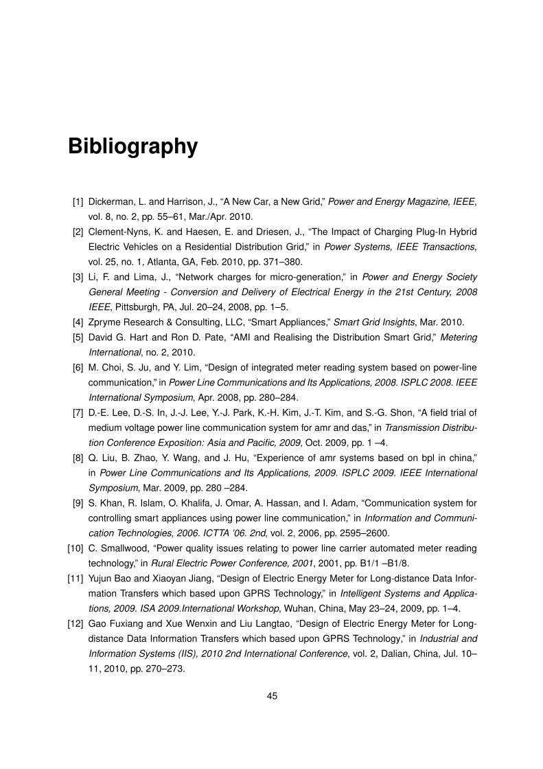
Bibliography
[1] Dickerman, L. and Harrison, J., “A New Car, a New Grid,” Power and Energy Magazine, IEEE,
vol. 8, no. 2, pp. 55–61, Mar./Apr. 2010.
[2] Clement-Nyns, K. and Haesen, E. and Driesen, J., “The Impact of Charging Plug-In Hybrid
Electric Vehicles on a Residential Distribution Grid,” in Power Systems, IEEE Transactions,
vol. 25, no. 1, Atlanta, GA, Feb. 2010, pp. 371–380.
[3] Li, F. and Lima, J., “Network charges for micro-generation,” in Power and Energy Society
General Meeting - Conversion and Delivery of Electrical Energy in the 21st Century, 2008
IEEE, Pittsburgh, PA, Jul. 20–24, 2008, pp. 1–5.
[4] Zpryme Research & Consulting, LLC, “Smart Appliances,” Smart Grid Insights, Mar. 2010.
[5] David G. Hart and Ron D. Pate, “AMI and Realising the Distribution Smart Grid,” Metering
International, no. 2, 2010.
[6] M. Choi, S. Ju, and Y. Lim, “Design of integrated meter reading system based on power-line
communication,” in Power Line Communications and Its Applications, 2008. ISPLC 2008. IEEE
International Symposium, Apr. 2008, pp. 280–284.
[7] D.-E. Lee, D.-S. In, J.-J. Lee, Y.-J. Park, K.-H. Kim, J.-T. Kim, and S.-G. Shon, “A field trial of
medium voltage power line communication system for amr and das,” in Transmission Distribu-
tion Conference Exposition: Asia and Pacific, 2009, Oct. 2009, pp. 1 –4.
[8] Q. Liu, B. Zhao, Y. Wang, and J. Hu, “Experience of amr systems based on bpl in china,”
in Power Line Communications and Its Applications, 2009. ISPLC 2009. IEEE International
Symposium, Mar. 2009, pp. 280 –284.
[9] S. Khan, R. Islam, O. Khalifa, J. Omar, A. Hassan, and I. Adam, “Communication system for
controlling smart appliances using power line communication,” in Information and Communi-
cation Technologies, 2006. ICTTA ’06. 2nd, vol. 2, 2006, pp. 2595–2600.
[10] C. Smallwood, “Power quality issues relating to power line carrier automated meter reading
technology,” in Rural Electric Power Conference, 2001, 2001, pp. B1/1 –B1/8.
[11] Yujun Bao and Xiaoyan Jiang, “Design of Electric Energy Meter for Long-distance Data Infor-
mation Transfers which based upon GPRS Technology,” in Intelligent Systems and Applica-
tions, 2009. ISA 2009.International Workshop, Wuhan, China, May 23–24, 2009, pp. 1–4.
[12] Gao Fuxiang and Xue Wenxin and Liu Langtao, “Design of Electric Energy Meter for Long-
distance Data Information Transfers which based upon GPRS Technology,” in Industrial and
Information Systems (IIS), 2010 2nd International Conference, vol. 2, Dalian, China, Jul. 10–
11, 2010, pp. 270–273.
45

[13] Anderson, M., “WiMax for smart grids,” Spectrum, IEEE, vol. 47, no. 7, p. 14, Jul. 2010.
[14] Li Li and Xiaoguang Hu and Weicun Zhang, “Design of an ARM-based power meter having
WIFI wireless communication module,” in Industrial Electronics and Applications, 2009. ICIEA
2009. 4th IEEE Conference, Xi’an, China, May 25–27, 2009, pp. 403–407.
[15] “A socio-economic analysis of wimax,” in Application of Information and Communication Tech-
nologies, 2009. AICT 2009. International Conference, Oct. 2009, pp. 1 –6.
[16] Koay, B.S. and Cheah, S.S. and Sng, Y.H. and Chong, P.H.J. and Shum, P. and Tong, Y.C.
and Wang, X.Y. and Zuo, Y.X. and Kuek, H.W., “Design and implementation of Bluetooth
energy meter,” in Information, Communications and Signal Processing, 2003. 4th International
Conference, vol. 3, Dec. 15–18, 2003, pp. 1474–1477.
[17] Peng Xuange and Xiao Ying, “An Embedded Electric Meter Based on Bluetooth Data Ac-
quisition System,” in Education Technology and Computer Science (ETCS), 2010 Second
International, Wuhan, China, Mar. 6–7, 2009, pp. 667–670.
[18] Al-Kassem, I. and Sharafeddine, S. and Dawy, Z., “BlueHRT: Hybrid Ring Tree Scatternet
Formation in Bluetooth Networks,” in Computers and Communications, 2009. ISCC 2009.
IEEE Symposium, Sousse, Tunisia, Jul. 5–8, 2009, pp. 165–169.
[19] Alkhrabash, A.-A.S. and Elshebani, M., “Routing schemes for bluetooth scatternet applicable
to mobile ad-hoc networks,” in Telecommunication in Modern Satellite, Cable, and Broadcast-
ing Services, 2009. TELSIKS ’09. 9th International Conference, Niš, Serbia, Oct. 7–9, 2009,
pp. 560–563.
[20] Jingjing Wang, “A new formation algorithm of Bluetooth Ad hoc networks,” in Control and
Decision Conference, 2009. CCDC ’09. Chinese, Guilin, China, Jun. 17–19, 2009, pp. 1291–
1295.
[21] T. Arnewid, “Ami in the city of goteborg,” Metering International, no. 4, pp. 76–79, 2007.
[22] N.Escravana, R.Lascas, M.Nunes, C.Anjos, H.Sarmento, A.Casaca, T.Silva, J.Lageira, and
J.Moreira, “Proposta de arquitectura,” Projecto Arquitectura de Comunicações do INOVGRID,
INOV, Tech. Rep. 0.8, Nov. 2008.
[23] ZigBee Alliance. (2010, Mar.) Timelox ab with zigbee; increasing hotel security worldwide.
ZigBee Success Stories. [Online]. Available: http://www.zigbee.org/imwp/download.asp?
ContentID=15272
[24] ZigBee Alliance. (2009) Awarepoint with zigbee improve patient care and the bottom
line. ZigBee Success Stories. [Online]. Available: http://www.zigbee.org/imwp/download.asp?
ContentID=15796
[25] ZigBee Alliance. (2010, Mar.) Landis+gyr and zigbee advanced metering for the intelligent
electric grid. ZigBee Success Stories. [Online]. Available: http://www.zigbee.org/imwp/
download.asp?ContentID=15796
[26] ZigBee Alliance. (2009, Apr.) ZigBee Alliance Plans Further Integration of Internet Protocol
Standards. Pdf. [Online]. Available: http://zigbee.org/imwp/idms/popups/pop_download.asp?
contentID=15754
46

[27] ZigBee Alliance. (2010, Mar.) ZigBee and Wi-Fi Alliances to Collaborate on Smart Grid
Wireless Networking. Pdf. [Online]. Available: http://zigbee.org/imwp/idms/popups/pop_
download.asp?contentID=17400
[28] L. Hui, “A meter reading system based on wsn,” in Optics Photonics and Energy Engineering
(OPEE), 2010 International Conference, vol. 1, May 2010, pp. 311 –314.
[29] S. De-chao and Z. Shao-hua, “Resarch and design of meter reading system,” in Circuits,
Systems, Signal and Telecommunications (CISST). 2009 3rd International Conference, 2009.
[30] H. Y. Tung, K. F. Tsang, and K. L. Lam, “Zigbee sensor network for advanced metering in-
frastructure,” in Consumer Electronics (ICCE), 2010 Digest of Technical Papers International
Conference, Jan. 2010, pp. 95 –96.
[31] S.-W. Luan, J.-H. Teng, S.-Y. Chan, and L.-C. Hwang, “Development of a smart power meter
for ami based on zigbee communication,” in Power Electronics and Drive Systems, 2009.
PEDS 2009. International Conference, Nov. 2009, pp. 661 –665.
[32] ZigBee Alliance, “ZigBee Specification,” ZigBee Document 053474r17, Jan. 2008.
[33] “Wireless Medium Access Control (MAC) and Physical Layer (PHY) Specifications for Low-
Rate Wireless Personal Area Networks (WPANs),” IEEE Std 802.15.4™-2006, Sep. 2006.
[34] ZigBee Alliance, “ZigBee Cluster Library Specification,” ZigBee Document 075123r01, Oct.
2007.
[35] “ZigBee Smart Energy Profile™ 2.0 Technical Requirements Document,” ZigBee Document
095449 Draft, Dec. 2009.
[36] G. Mulligan, “The 6lowpan architecture,” in EmNets ’07: Proceedings of the 4th workshop on
Embedded networked sensors. New York, NY, USA: ACM, 2007, pp. 78–82.
[37] “MC13224V Technical Data, Rev. 1.2,” Doc. MC1322x, Freescale Semiconductor, p. 50, Feb.
2009.
[38] “Manufacturing with the Land Grid Array Package,” Application Note AN2920, Freescale Semi-
conductor, p. 16, 2008.
[39] “JN5139 Data Sheet, Rev. 1.6,” Jennic, p. 85, Sep. 2008.
[40] “EM250 Data Sheet, Rev. 2.1,” Doc. 120-0082-000I, Ember, p. 117, Jul. 2006.
[41] “CC2430 Data Sheet, Rev. 2.1,” Doc. SWRS036F, Texas Instruments, p. 211, May 2007.
[42] D. H. J. Zhang, “Linear regulator and switching mode power supply basics,” in Embedded
Systems Conference (ESC), Apr. 2006.
[43] “Linear Regulators in Portable Applications,” Application Note 751, Maxim/Dallas, p. 11, 2001.
[44] T. Nass and A. Andersen, “Powering Low-Power RF Products,” Texas Instruments, Design
Note DN019, 2009.
[45] Simjee, F.I. and Chou, P.H., “Everlast: Long-life, Supercapacitor-operated Wireless Sensor
Node,” in Low Power Electronics and Design, 2006. ISLPED’06, Tegernsee, Oct. 4–6, 2006,
pp. 197–202.
[46] C. Park and P. Chou, “AmbiMax: Autonomous Energy Harvesting Platform for Multi-Supply
Wireless Sensor Nodes,” in Sensor and Ad Hoc Communications and Networks, 2006.
SECON ’06., vol. 1, Reston, VA, Sep. 28, 2006, pp. 168–177.
47

[47] Sogorb, T. and Llario, J.V. and Pelegri, J. and Lajara, R. and Alberola, J., “Studying the Fea-
sibility of Energy Harvesting from Broadcast RF Station for WSN,” in Instrumentation and
Measurement Technology Conference Proceedings, 2008. IMTC 2008. IEEE, Victoria, BC,
May 12–15, 2008, pp. 1360–1363.
[48] Seah, W.K.G. and Zhi Ang Eu and Hwee-Pink Tan, “Wireless Sensor Networks Powered by
Ambient Energy Harvesting (WSN-HEAP) - Survey and Challenges,” in Wireless VITAE 2009,
Aalborg, May 17–20, 2009, pp. 1–5.
[49] I. Buchmann, Batteries in a Portable World, 2nd ed. Cadex Electronics Inc, 2001.
[50] Panasonic, “Nickel Metal Hydride Batteries,” Aug. 2005.
[51] R. Wallace, “Antenna Selection Guide,” Texas Instruments, Application Note AN058, 2009.
[52] N. R. Subramanian and N. Kirkeby, “Anaren 0404 (BD2425N50200A00) balun optimized for
Texas Instruments CC2430 Transceiver,” Anaren, Balun Application Note ANN-2002, Aug. 31,
2007.
[53] G. E. Jonsrud, “Folded dipole antenna for CC2400, CC2420, CC2430, CC2431, and CC2480,”
Texas Instruments, Application Note AN040, 2008.
[54] A. Andersen, “2.4 GHz Inverted F Antenna,” Texas Instruments, Design Note DN0007, 2008.
[55] A. Andersen, “Small Size 2.4 GHz PCB antenna,” Texas Instruments, Application Note AN043,
2008.
[56] K. Mitzner, Complete PCB Design Using OrCad Capture and Layout, Elsevier, Ed. Newnes,
2007.
[57] K. Mitzner, Complete PCB Design Using OrCad Capture and Layout. Newton, MA, USA:
Newnes, 2007.
[58] IEC TC 13, “EN 62056-21, Electricity metering - Data exchange for meter reading, tariff and
load control - Part21: Direct local data exchange,” International Electrotechnical Commission,
CENELEC, Brussels, Standard CEI/IEC 62056-21:2002, 2002.
[59] Texas Instruments, “Z-Stack Developer’s Guide,” Document F8W-2006-0022, 2007.
48

Appendices
49


Appendix A
ZigBee Solutions for ProductDevelopment
This appendix is the result of a survey done in order to choose the chip upon which the ZigBee
module would be built and to understand the current market state of the ZigBee technology. The
ZigBee Alliance website provided information about the companies involved with ZigBee technol-
ogy.
The survey focused hardware solutions here organised in four tables. Table A.1 presents avail-
able integrated circuits. Detailed information about the chips is presented in table A.2. Table A.3
describes the development kits indicating the hardware platform they use, their features and their
cost. Finally, table A.4 aggregates information about standalone modules. Modules are surface
mountable PCBs with integrated circuits and the basic circuitry required to make them functional.
We conclude that there are four major ZigBee chips manufacturers, Ember, Jennic, Texas
Instruments (TI) and Freescale. Development kits exhibit great diversity in terms of features and
software, and normally provide a stack that implements the IEEE 802.15.4, ZigBee, or some pro-
prietary protocol. They are usually intended to develop a particular integrated circuit. Standalone
modules ease development of new ZigBee solutions by providing RF certification while allowing
flexibility to choose antenna connectors and transmit power levels.
51
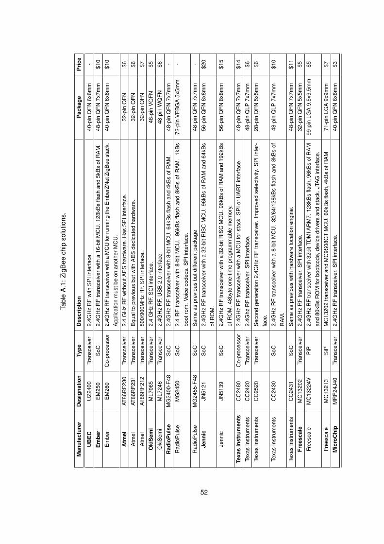
Tabl
eA
.1:
ZigB
eech
ipso
lutio
ns.
Man
ufac
ture
rD
esig
natio
nTy
peD
escr
iptio
nP
acka
geP
rice
UB
EC
UZ2
400
Tran
scei
ver
2.4G
Hz
RF
with
SP
Iint
erfa
ce.
40-p
inQ
FN6x
6mm
-
Em
ber
EM
250
SoC
2.4G
Hz
RF
trans
ceiv
erw
itha
16-b
itM
CU
.12
8kB
sfla
shan
d5k
Bs
ofR
AM
.48
-pin
QFN
7x7m
m$1
0
Em
ber
EM
260
Co-
proc
esso
r2.
4GH
zR
Ftra
nsce
iver
with
aM
CU
forr
unni
ngth
eE
mbe
rZN
etZi
gBee
stac
k.
App
licat
ion
mus
tbe
onan
othe
rMC
U.
40-p
inQ
FN6x
6mm
$10
Atm
elAT
86R
F230
Tran
scei
ver
2.4
GH
zR
Fw
ithou
tAE
Sha
rdw
are.
Has
SP
Iint
erfa
ce.
32-p
inQ
FN$6
Atm
elAT
86R
F231
Tran
scei
ver
Equ
alto
prev
ious
butw
ithA
ES
dedi
cate
dha
rdw
are.
32-p
inQ
FN$6
Atm
elAT
86R
F212
Tran
scei
ver
800/
900M
Hz
RF.
SP
Iint
erfa
ce.
32-p
inQ
FN$7
Oki
Sem
iM
L706
5Tr
ansc
eive
r2.
4G
Hz
RF.
SC
Iint
erfa
ce.
48-p
inV
QFN
$5
Oki
Sem
iM
L724
6Tr
ansc
eive
r2.
4GH
zR
F.U
SB
2.0
inte
rface
.48
-pin
WQ
FN$6
Rad
ioP
ulse
MG
2400
-F48
SoC
2.4G
Hz
RF
trans
ceiv
erw
ith8-
bitM
CU
.64
kBs
flash
and
4kB
sof
RA
M.
48-p
inQ
FN7x
7mm
-
Rad
ioP
ulse
MG
2450
SoC
2.4
RF
trans
ceiv
erw
ith8-
bit
MC
U.
96kB
sfla
shan
d8k
Bs
ofR
AM
.1k
Bs
boot
rom
.Vo
ice
code
cs.
SP
Iint
erfa
ce.
72-p
inV
FBG
A5x
5mm
-
Rad
ioP
ulse
MG
2455
-F48
SoC
Sam
eas
prev
ious
butd
iffer
entp
acka
ge48
-pin
QFN
7x7m
m-
Jenn
icJN
5121
SoC
2.4G
Hz
RF
trans
ceiv
erw
itha
32-b
itR
ISC
MC
U.
96kB
sof
RA
Man
d64
kBs
ofR
OM
.
56-p
inQ
FN8x
8mm
$20
Jenn
icJN
5139
SoC
2.4G
Hz
RF
trans
ceiv
erw
itha
32-b
itR
ISC
MC
U.9
6kB
sof
RA
Man
d19
2kB
s
ofR
OM
.48
byte
one-
time
prog
ram
mab
lem
emor
y.
56-p
inQ
FN8x
8mm
$15
Texa
sIn
stru
men
tsC
C24
80C
o-pr
oces
sor
2.4G
Hz
RF
trans
ceiv
erw
itha
MC
Ufo
rsta
ck.
SP
IorU
AR
Tin
terfa
ce.
48-p
inQ
FN7x
7mm
$14
Texa
sIn
stru
men
tsC
C24
20Tr
ansc
eive
r2.
4Ghz
RF
trans
ceiv
er.
SP
Iint
erfa
ce.
48-p
inQ
LP7x
7mm
$6
Texa
sIn
stru
men
tsC
C25
20Tr
ansc
eive
rS
econ
dge
nera
tion
2.4G
Hz
RF
trans
ceiv
er.
Impr
oved
sele
ctiv
ity.
SP
Iint
er-
face
.
28-p
inQ
FN5x
5mm
$6
Texa
sIn
stru
men
tsC
C24
30S
oC2.
4GH
zR
Ftra
nsce
iver
with
a8-
bitM
CU
.32
/64/
128k
Bs
flash
and
8kB
sof
RA
M.
48-p
inQ
LP7x
7mm
$10
Texa
sIn
stru
men
tsC
C24
31S
oCS
ame
aspr
evio
usw
ithha
rdw
are
loca
tion
engi
ne.
48-p
inQ
FN7x
7mm
$11
Free
scal
eM
C13
202
Tran
scei
ver
2.4G
Hz
RF
trans
ceiv
er.
SP
Iint
erfa
ce.
32-p
inQ
FN5x
5mm
$5
Free
scal
eM
C13
224V
PiP
2.4G
Hz
RF
trans
ceiv
erw
ith32
bitT
DM
IAR
M7.
128k
Bs
flash
,96k
Bs
ofR
AM
and
80kB
sR
OM
forb
ootc
ode,
devi
cedr
iver
san
dst
ack.
JTA
Gin
terfa
ce.
99-p
inLG
A9.
5x9.
5mm
$5
Free
scal
eM
C13
213
SiP
MC
1320
2tra
nsce
iver
and
MC
9S08
GT
MC
U.
60kB
sfla
sh,4
kBs
ofR
AM
71-p
inLG
A9x
9mm
$7
Mic
roC
hip
MR
F24J
40Tr
ansc
eive
r2.
4GH
zR
Ftra
nsce
iver
.S
PIi
nter
face
.40
-pin
QFN
6x6m
m$3
52

Tabl
eA
.2:
Det
aile
din
form
atio
nof
ZigB
eesi
ngle
chip
solu
tions
.
Man
ufac
ture
r/Ty
peE
PR
OM
RA
MM
AC
AE
SR
xC
urre
ntTx
Cur
rent
TxPo
wer
Pac
kage
Pri
ceR
efer
ence
(kB
s)(k
Bs)
hard
war
eha
rdw
are
(mA
)(m
A)
(dbm
)
Em
ber
SoC
128
5Ye
sYe
s28
243
48-p
inQ
FN$1
0E
M25
0(2
.4G
Hz
and
16bi
t)7x
7mm
Em
ber
Co-
proc
esso
r-
-Ye
sYe
s35
,535
,52,
540
-pin
QFN
$10
EM
260
(2.4
GH
zan
d16
bit)
6x6m
m
Em
ber
Tran
scei
ver
--
Yes
Yes
19,7
17,4
048
-pin
QLP
$8E
M24
20(2
.4G
Hz)
7x7m
m
Jenn
icS
oC64
96Ye
sYe
s50
450
56-p
inQ
FN$2
0JN
5121
(2.4
GH
zan
d32
bit)
8x8m
m
Jenn
icS
oC19
296
Yes
Yes
3434
356
-pin
QFN
$15
JN51
39(2
.4G
Hz
and
32bi
t)(R
OM
)8x
8mm
Texa
sC
o-pr
oces
sor
128
8P
artia
lYe
s27
270
48-p
inQ
FN$1
4C
C24
80A
1(2
.4G
Hz)
7X7m
m
Texa
sTr
ansc
eive
r-
-Ye
sYe
s18
,525
,84
28-p
inQ
FN$6
CC
2520
(2.4
GH
z)5x
5mm
Texa
sS
oC12
88
Yes
Yes
2727
048
-pin
QFN
$11
CC
2431
(2.4
GH
zan
d8b
it)7X
7mm
Texa
sS
oC32
/64/
128
8Ye
sYe
s27
270
48-p
inQ
LP$1
0C
C24
30(2
.4G
Hz
and
8bit)
7X7m
m
Texa
sTr
ansc
eive
r-
-Ye
sYe
s18
,817
,40
48-p
inQ
LP$6
CC
2420
(2.4
GH
z)7X
7mm
Free
scal
eP
iP12
8+
8096
Yes
Yes
2229
499
-pin
LGA
$12
MC
1322
4V(2
.4G
Hz
and
32bi
t)(s
eete
xt)
9.5x
9.5m
m
Free
scal
eS
iP32
2N
oN
o40
353
71-p
inLG
A$5
MC
1321
2(2
.4G
Hz
and
8bit)
9X9m
m
Free
scal
eS
iP60
4N
oN
o40
353
71-p
inLG
A$7
MC
1321
3(2
.4G
Hz
and
8bit)
9X9m
m
Free
scal
eTr
ansc
eive
r-
-N
oN
o40
353
32-p
inQ
FN$5
MC
1320
2(2
.4G
Hz)
5X5m
m
53

Tabl
eA
.3:
ZigB
eede
velo
pmen
tkits
.
Man
ufac
ture
rR
efer
ence
Tran
scei
ver
Mic
ro-C
ontr
olle
rS
oCD
escr
iptio
nP
rice
NE
CE
lect
roni
csTK
-850
/SG
2+U
ZU
Z240
0V
850E
S/S
G2
-32
bitC
PU
,384
KB
Flas
h,32
KB
Ram
Com
pile
r(1
28K
Bm
ax),
Deb
ugge
r,TC
P/IP
HTT
P,S
MTP
,P
OP
3an
dIE
EE
MA
Cst
ack
libra
ry
-
NE
CE
lect
roni
csTK
-78K
0R/K
G3+
UZ
UZ2
400
78K
0R/K
G3
-16
bit
CP
U,
512K
BFl
ash,
30K
BR
AM
,C
ompi
ler
(64K
Bm
ax),
debu
gger
and
IEE
EM
AC
stac
k
-
NE
CE
lect
roni
cs78
k0R
UZ
Stic
kU
Z240
078
K0R
/KE
3-
16bi
tCP
U,2
56K
BFl
ash,
12K
BR
AM
-
NE
CE
lect
roni
csTK
-78K
0/K
F2+U
ZU
Z240
078
K0/
KF2
-8b
itC
PU
,128
KB
Flas
h,7K
BR
AM
Com
pile
r(3
2KB
max
),de
-
bugg
er,a
ndIE
EE
MA
Cst
ack
-
NE
CE
lect
roni
cs78
K0
UZ
Stic
kU
Z240
078
K0/
KE
2-
8bit
CP
U,1
28K
BFl
ash,
7KB
RA
M-
Sky
ley
--
-S
DK
and
appl
icat
ions
that
can
confi
gure
netw
orks
with
outt
he
need
ofpr
ogra
min
gU
ses
NE
CE
L/S
KY
LEY
ZigB
eest
ack
$1.3
00
Em
ber
EM
250-
JMP
-R-
-E
M25
0/E
M26
0H
ardw
are:
3xE
M25
0/E
M26
0R
adio
Con
trolM
odul
es(R
CM
)
Boa
rd3x
EM
250/
EM
260
Bre
akou
tB
oard
3xE
M25
0/E
M26
0
InS
ight
Ada
pter
1xM
CC
ard
toS
MA
Cab
le3x
InS
ight
Port
Ca-
ble
3xPo
wer
Sup
plie
san
dB
atte
ryP
ack
3xE
xten
ded
Deb
ug
Cab
le1x
8Po
rtS
witc
hw
/4
xP
OE
port
sS
ampl
eC
hips
:10x
EM
250/
EM
260
Chi
psS
oftw
are:
1lic
ense
InS
ight
Des
ktop
De-
velo
perE
ditio
nxI
DE
Com
pile
r
$2.5
00
Em
ber
EM
250-
DE
V-
-E
M25
0/E
M26
0H
ardw
are:
8xE
M25
0/E
M26
0R
adio
Con
trolM
odul
es(R
CM
)
Boa
rd8x
EM
250/
EM
260
Bre
akou
tB
oard
8xE
M25
0/E
M26
0
InS
ight
Ada
pter
1xM
CC
ard
toS
MA
Cab
le8x
InS
ight
Port
Ca-
ble
8xPo
wer
Sup
plie
san
dB
atte
ryP
ack
8xE
xten
ded
Deb
ug
Cab
le1x
16Po
rtS
witc
hw
/8x
PO
Epo
rts
Sam
ple
Chi
ps:
10x
EM
250/
EM
260
Chi
psS
oftw
are:
1lic
ense
InS
ight
Des
ktop
Pro
-
fess
iona
lEdi
tion
xID
EC
ompi
lerT
rain
ing:
One
day
one
pers
on
$10.
000
Em
ber
EM
250-
EK
-R-
--
Rad
ioM
odul
ew
ithC
arrie
rB
oard
AA
batte
ries
Pow
ersu
pply
US
BC
able
sA
nten
nas
InS
ight
Des
ktop
Sof
twar
eU
serG
uide
$500
Con
tinue
son
next
page
54

Tabl
eA
.3:
ZigB
eede
velo
pmen
tkits−
cont
inue
d.
Man
ufac
ture
rR
efer
ence
Tran
scei
ver
Mic
ro-C
ontr
olle
rS
oCD
escr
iptio
nP
rice
Mes
hNet
ics
MN
ZB-D
KL-
24AT
86R
F230
ATM
ega1
281v
-3
xM
eshB
ean
deve
lopm
ent
boar
dsfe
atur
ing
diffe
rent
an-
tenn
aty
pes
3x
ZigB
itO
EM
mod
ules
mou
nted
onM
eshB
ean
boar
ds3
xU
SB
cabl
es2
xex
tern
alin
terfa
ceca
bles
1x
soft-
war
e(S
eria
lNet
(AT
com
man
ds)
and
WS
NM
onito
r)&
docu
-
men
tatio
nC
D45
days
ofsu
ppor
t
$400
Mes
hNet
ics
MN
ZB-D
KC
-24
AT86
RF2
30AT
Meg
a128
1v-
Sam
eha
spr
evio
uson
e,bu
toffe
rsm
ore
supp
ort(
1yea
r).E
arly
aces
sto
new
softw
are,
Ger
ber
File
s,bo
otlo
ader
sour
ceco
de.
Ser
ialN
etE
xten
sion
s(m
ake
your
own)
$900
Mes
hNet
ics
MN
ZB-D
KL-
A24
AT86
RF2
30AT
Meg
a128
1v-
2x
Mes
hBea
nA
mp
deve
lopm
entb
oard
s2
xZi
gBit
Am
pO
EM
mod
ules
mou
nted
onM
eshB
ean
Am
pbo
ards
2x
US
Bca
bles
2x
exte
rnal
inte
rface
cabl
es1
xso
ftwar
e(S
eria
lNet
(AT
com
-
man
ds)
and
WS
NM
onito
r)&
docu
men
tatio
nC
D45
days
of
supp
ort
$400
Mes
hNet
ics
MN
ZB-D
KC
-A24
AT86
RF2
30AT
Meg
a128
1v-
Sam
eha
spr
evio
uson
e,bu
toffe
rsm
ore
supp
ort(
1yea
r).E
arly
aces
sto
new
softw
are,
Ger
ber
File
s,bo
otlo
ader
sour
ceco
de.
Ser
ialN
etE
xten
sion
s(m
ake
your
own)
$900
Oki
sem
iO
KI-Z
DK
ML7
065
ML6
7Q40
61-
1x-
Oki
ZigB
eeN
etw
ork
Eva
luat
ion/
Dem
o(z
NE
D)
boar
d2x
-IE
EE
802.
15.4
US
Bra
dio
dong
les
Eva
luat
ion
vers
ions
of:
ZigB
eest
ack
for
Oki
’sA
RM
7ba
sed
4050
/406
0se
ries
MC
Us
Dai
ntre
e’s
Net
wor
kA
naly
zer
softw
are
IAR
sE
mbe
dded
Wor
k-
benc
hfo
rAR
MS
egge
r’sem
bOS
RTO
S
$500
Rad
ioP
ulse
MG
245X
-ZD
K-
-M
G24
55/M
G24
506x
PC
Inte
rface
Boa
rd(M
G24
5X-E
VB
6xC
hip
Inte
rface
Boa
rd
25x
ZigB
eeS
ingl
eC
hip
(MG
2455
orM
G24
50)
6xU
sbca
-
bles
2x5V
DC
Ada
pter
s6x
Dip
ole
Ant
enna
s(3
with
2dB
i
and
34d
Bi)
2x9-
pin
RS
-232
Ser
ial
Cab
le1x
Pac
ket
Ana
-
lyze
rada
pter
2xE
ther
netC
able
2xX
PO
RT
(Ser
ialt
oE
ther
net)
Sof
twar
e:P
rofil
e-S
imul
ator
,P
rofil
e-B
uild
er,
Pac
ket-A
naly
zer,
Dev
ice-
Pro
gram
mer
,C
P21
01D
river
,C
P21
01U
SB
IDS
ET,
XP
OR
Tde
vice
inst
alle
r,
$4.0
00
Con
tinue
son
next
page
55

Tabl
eA
.3:
ZigB
eede
velo
pmen
tkits−
cont
inue
d.
Man
ufac
ture
rR
efer
ence
Tran
scei
ver
Mic
ro-C
ontr
olle
rS
oCD
escr
iptio
nP
rice
Rad
ioP
ulse
MG
245X
-EV
K-
-M
G24
55/M
G24
512x
PC
Inte
rface
Boa
rd(M
G24
5X-E
VB
2xC
hip
Inte
rface
Boa
rd
25x
ZigB
eeS
ingl
eC
hip
(MG
2455
orM
G24
50)
2xU
sbca
-
bles
2x5V
DC
Ada
pter
s6x
Dip
ole
Ant
enna
s(2
dBi))
2x9-
pin
RS
-232
Ser
ialC
able
2xE
ther
netC
able
Sof
twar
e:D
evic
e-
Pro
gram
mer
,C
P21
01D
river
,C
P21
01U
SB
IDS
ET,
XP
OR
T
devi
cein
stal
ler,
-
Jenn
icJN
5139
-EK
000
--
JN51
39C
ontro
ller
Boa
rd4x
Sen
sors
Boa
rdU
SB
2xH
igh
Pow
erm
od-
ules
GN
U-b
ased
tool
chai
n(a
nsiC
,C
++co
mpi
ler,
debu
gger
,
flash
prog
ram
mer
)S
oftw
are:
JenN
etne
twor
klib
rarie
s,m
icro
-
cont
rolle
ran
dpe
riphe
ral
libra
ries
Cod
e::B
lock
(IDE
)D
aint
ree
Net
wor
ksS
enso
rNet
wor
kA
naly
ser(
tria
l)
$450
Jenn
icJN
5121
-EK
010
--
JN51
39Th
esa
me
butw
ithZi
gBee
stac
kin
stea
dof
the
JenN
etne
twor
k
libra
ries
$500
Jenn
icJN
5121
-EK
020
--
JN51
393x
Sen
sorB
oard
Mod
ule
with
cera
mic
ante
nna
RS
23B
atte
ries
2xU
SB
cabl
es.S
oftw
are:
JenN
etst
ack
(CA
PI)
AT-J
enie
IEE
E
MA
CFr
eeS
DK
$220
Slic
onLa
bsZi
gBee
-2.4
-DK
--
C80
51F1
216x
2.4G
Hz
802.
15.4
/Zig
Bee
deve
lopm
ent
boar
dsw
ithan
ten-
nas
1xPo
wer
supp
ly(9
V,1.
5A)
1xU
SB
debu
gad
apte
r2x
US
Bca
bles
6x9V
batte
ries
Sof
twar
e:M
AC
firm
war
eH
eli-
com
mst
ack
Sili
con
Labs
IDE
(free
todo
wnl
oad)
.E
valu
atio
n
vers
ions
ofK
eilc
ompi
ler,
asse
mbl
eran
dlin
ker.
Driv
ers
and
bund
leso
ftwar
ew
ithde
mon
stra
tions
$950
Sili
con
Labs
802.
15.4
-2.4
-DK
--
C80
51F1
212x
2.4G
Hz
802.
15.4
/Zig
Bee
deve
lopm
ent
boar
dsw
ithan
ten-
nas
1xPo
wer
supp
ly(9
V,1.
5A)
1xU
SB
debu
gad
apte
r2x
US
Bca
bles
2x9V
batte
ries
Sof
twar
e:M
AC
firm
war
eH
eli-
com
mst
ack
Sili
con
Labs
IDE
(free
todo
wnl
oad)
.E
valu
atio
n
vers
ions
ofK
eilc
ompi
ler,
asse
mbl
eran
dlin
ker.
Driv
ers
and
bund
leso
ftwar
ew
ithde
mon
stra
tions
$365
Con
tinue
son
next
page
56

Tabl
eA
.3:
ZigB
eede
velo
pmen
tkits−
cont
inue
d.
Man
ufac
ture
rR
efer
ence
Tran
scei
ver
Mic
ro-C
ontr
olle
rS
oCD
escr
iptio
nP
rice
Sili
con
Labs
DAU
B-D
K1
2400
--
-2x
OE
M-D
AUB
124
00Zi
gBee
US
BD
ongl
es.
Pro
toco
lan
al-
yser
softw
are
driv
ers.
The
dong
leis
avai
labl
ew
itha
choi
ceof
two
driv
erop
tions
:The
802.
15.4
driv
ers
prov
ide
dire
ctac
cess
toth
e80
2.15
.4M
AC
in-
terfa
ce.
The
ZigB
eedr
iver
sal
low
the
dong
leto
oper
ate
with
in
aZi
gBee
netw
ork
and
expo
seth
eA
F/ZD
OA
pplic
atio
nIn
ter-
face
s.
$152
Hel
icom
mE
ZDK
1220
PA-
C80
51F1
21-
6xP
CIn
terfa
ceB
oard
with
inte
gral
IP-L
ink
1220
PA(p
ower
am-
plifi
ed)
WIN
-Vie
wN
etw
orki
ngM
anag
emen
tSof
tWar
eM
odul
e
AP
Isp
ecifi
catio
ns,
netw
orki
ngex
ampl
esan
dtu
toria
lsA
llre
-
quire
dca
bles
and
pow
ersu
pplie
s
$2.7
00
Dig
iX
B24
-BP
DK
-WM
C9S
08G
T60
MC
1319
2-
1xX
Bee
ZB/Z
Net
2.5
w/W
ireA
nten
na(C
oord
inat
or)1
xX
Bee
ZB/Z
Net
2.5
w/
Chi
pA
nten
na(R
oute
r)1x
XB
eeZB
/ZN
et2.
5
w/
U.fl
Con
nect
or(R
oute
r)2x
XB
ee-P
RO
ZB/Z
Net
2.5
w/
RP
SM
AC
onne
ctor
(Rou
ter)
3xR
S-2
32D
evel
opm
entB
oard
s
2xU
SB
Dev
elop
men
tBoa
rds
3x2.
4G
Hz
RP
SM
AA
nten
na1x
U.fl
toR
PS
MA
Ada
pter
Cab
le3x
RS
-232
Ser
ialC
able
s2x
US
B
Cab
les
1xPo
wer
Ada
pter
3x9V
Bat
tery
Clip
s3x
Ada
pter
s
$350
Dig
iX
B24
-DM
DK
MC
9S08
GT6
0M
C13
192
-1x
XB
ee-P
RO
Dig
iMes
h2.
4w
/R
PS
MA
conn
ecto
r1x
XB
ee-
PR
OD
igiM
esh
2.4
w/U
.flco
nnec
tor2
xX
Bee
Dig
iMes
h2.
4w
/
wire
ante
nna
s2x
RS
-232
deve
lopm
entb
oard
s2x
US
Bde
vel-
opm
entb
oard
s2x
RS
-232
seria
lcab
les
2xU
SB
cabl
es2x
2.4
GH
zR
PS
MA
Ant
enna
s2x
Pow
erA
dapt
er2x
9VB
atte
ryC
lip
Vario
usA
dapt
ers
-
Texa
sC
C25
20D
KC
C25
20M
SP
430F
2618
-3
xS
mar
tRF®
05E
B3
xC
C25
20E
Mev
alua
tion
mod
ules
3x
Ant
enna
s2
xC
CM
SP
-EM
430F
2618
1xM
SP
-FE
T430
UIF
de-
bug
inte
rface
3x
US
Bca
bles
Doc
umen
tsA
free,
code
size
limite
ded
ition
ofIA
RE
mbe
dded
Wor
kben
ch(IA
RK
icks
tart
)
$650
Con
tinue
son
next
page
57

Tabl
eA
.3:
ZigB
eede
velo
pmen
tkits−
cont
inue
d.
Man
ufac
ture
rR
efer
ence
Tran
scei
ver
Mic
ro-C
ontr
olle
rS
oCD
escr
iptio
nP
rice
Texa
sC
C24
20M
SP
430Z
DK
CC
2420
MS
P43
0FG
4618
-TI
’sZi
gBee
stac
k,Z-
Sta
ckfo
rM
SP
430
1xC
C24
20E
MK
2x
MS
P43
0E
xper
imen
terB
oard
1xP
rogr
amm
er
Free
softw
are
and
tria
lone
s,ne
twor
kan
alyz
ers,
pack
etsn
ifer,
stac
ks
$320
Texa
sC
C24
30ZD
K-
-C
C24
30TI
’sZi
gBee
stac
k,Z-
Sta
ck2x
Sm
artR
F04E
BE
valu
atio
n
Boa
rds
2xC
C24
30E
ME
valu
atio
nM
odul
es5x
CC
2430
DB
Dem
onst
ratio
nB
oard
sA
nten
nas
and
batte
ries
IAR
EW
8051
C-c
ompi
ler
with
C-S
PY
debu
gger
(30+
60da
ysev
alua
tion
li-
cens
e.)
Sen
sorN
etw
ork
Ana
lyze
rfro
mD
aint
ree
$1.5
00
Texa
sC
C24
31ZD
K-
-C
C24
31TI
’sZi
gBee
stac
k,Z-
Sta
ck2x
Sm
artR
F04E
BE
valu
atio
n
Boa
rds
2xC
C24
30E
ME
valu
atio
nM
odul
es5x
CC
2430
DB
Dem
onst
ratio
nB
oard
s10
xC
C24
31E
ME
valu
atio
nM
odul
es
10x
Bat
tery
Boa
rds
for
use
with
the
CC
2431
EM
sA
nten
nas
and
cabl
esIA
RE
W80
51C
-com
pile
rw
ithC
-SP
Yde
bugg
er
(30+
60da
ysev
alua
tion
licen
se.)
Sen
sor
Net
wor
kA
naly
zer
from
Dai
ntre
e
$2.0
00
Texa
sE
Z430
-RF2
480
CC
2480
MS
P43
0F22
74-
3xZi
gBee
Nod
es(e
Z430
-RF2
480
Targ
etB
oard
s)1x
US
Bdo
n-
gle
inte
rface
(MS
P-e
Z430
U)
2xpo
wer
edby
batte
rybo
ards
(eZ4
30-B
B)
4xA
AA
batte
ries
5xav
aila
ble
GP
IOde
velo
p-
men
tpin
sH
ighl
yin
tegr
ated
,ultr
a-lo
w-p
ower
MS
P43
0M
CU
2x
gene
ral-p
urpo
sedi
gita
lI/O
pins
conn
ecte
dto
gree
nan
dre
d
LED
sIn
terr
uptib
lepu
shbu
tton
fora
pplic
atio
nco
ntro
l
$100
Free
scal
e13
20x
DK
MC
1320
2-
-13
20x-
RFC
RF
daug
hter
card
MC
1320
22.
4G
Hz
RF
Tran
scei
verP
rinte
dF
ante
nna
SM
Aco
nnec
tion
CD
and
Use
r’s
Gui
deTh
isis
anha
rdw
are
only
Dau
ghte
rCar
d
$100
Free
scal
e13
21xD
SK
--
MC
1321
32x
1321
x-S
RB
(Sen
sor
Ref
eren
ceB
oard
)M
MA
7260
Q3-
axis
acce
lera
tion
sens
oran
dte
mpe
ratu
rese
nsor
Prin
ted
Fan
-
tenn
aC
odeW
arrio
rS
peci
alE
ditio
nID
EB
eeK
itw
ith90
-day
eval
uatio
nof
Bee
-Sta
ckB
atte
ries,
Cab
les
and
Pow
erA
dapt
ers
$250
Con
tinue
son
next
page
58
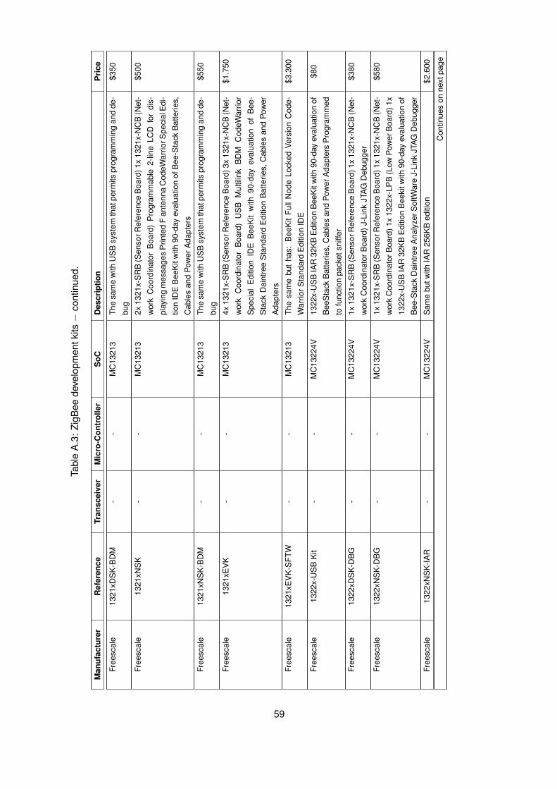
Tabl
eA
.3:
ZigB
eede
velo
pmen
tkits−
cont
inue
d.
Man
ufac
ture
rR
efer
ence
Tran
scei
ver
Mic
ro-C
ontr
olle
rS
oCD
escr
iptio
nP
rice
Free
scal
e13
21xD
SK
-BD
M-
-M
C13
213
The
sam
ew
ithU
SB
syst
emth
atpe
rmits
prog
ram
min
gan
dde
-
bug
$350
Free
scal
e13
21xN
SK
--
MC
1321
32x
1321
x-S
RB
(Sen
sorR
efer
ence
Boa
rd)1
x13
21x-
NC
B(N
et-
wor
kC
oord
inat
orB
oard
)P
rogr
amm
able
2-lin
eLC
Dfo
rdi
s-
play
ing
mes
sage
sP
rinte
dF
ante
nna
Cod
eWar
riorS
peci
alE
di-
tion
IDE
Bee
Kit
with
90-d
ayev
alua
tion
ofB
ee-S
tack
Bat
terie
s,
Cab
les
and
Pow
erA
dapt
ers
$500
Free
scal
e13
21xN
SK
-BD
M-
-M
C13
213
The
sam
ew
ithU
SB
syst
emth
atpe
rmits
prog
ram
min
gan
dde
-
bug
$550
Free
scal
e13
21xE
VK
--
MC
1321
34x
1321
x-S
RB
(Sen
sorR
efer
ence
Boa
rd)3
x13
21x-
NC
B(N
et-
wor
kC
oord
inat
orB
oard
)U
SB
Mul
tilin
kB
DM
Cod
eWar
rior
Spe
cial
Edi
tion
IDE
Bee
Kit
with
90-d
ayev
alua
tion
ofB
ee-
Sta
ckD
aint
ree
Sta
ndar
dE
ditio
nB
atte
ries,
Cab
les
and
Pow
er
Ada
pter
s
$1.7
50
Free
scal
e13
21xE
VK
-SFT
W-
-M
C13
213
The
sam
ebu
tha
s:B
eeK
itFu
llN
ode
Lock
edVe
rsio
nC
ode-
War
riorS
tand
ard
Edi
tion
IDE
$3.3
00
Free
scal
e13
22x-
US
BK
it-
-M
C13
224V
1322
x-U
SB
IAR
32K
BE
ditio
nB
eeK
itw
ith90
-day
eval
uatio
nof
Bee
Sta
ckB
atte
ries,
Cab
les
and
Pow
erA
dapt
ers
Pro
gram
med
tofu
nctio
npa
cket
sniff
er
$80
Free
scal
e13
22xD
SK
-DB
G-
-M
C13
224V
1x13
21x-
SR
B(S
enso
rRef
eren
ceB
oard
)1x
1321
x-N
CB
(Net
-
wor
kC
oord
inat
orB
oard
)J-L
ink
JTA
GD
ebug
ger
$380
Free
scal
e13
22xN
SK
-DB
G-
-M
C13
224V
1x13
21x-
SR
B(S
enso
rRef
eren
ceB
oard
)1x
1321
x-N
CB
(Net
-
wor
kC
oord
inat
orB
oard
)1x
1322
x-LP
B(L
owPo
wer
Boa
rd)1
x
1322
x-U
SB
IAR
32K
BE
ditio
nB
eeki
twith
90-d
ayev
alua
tion
of
Bee
-Sta
ckD
aint
ree
Ana
lyze
rSof
tWar
eJ-
Link
JTA
GD
ebug
ger
$580
Free
scal
e13
22xN
SK
-IAR
--
MC
1322
4VS
ame
butw
ithIA
R25
6KB
editi
on$2
.600
Con
tinue
son
next
page
59
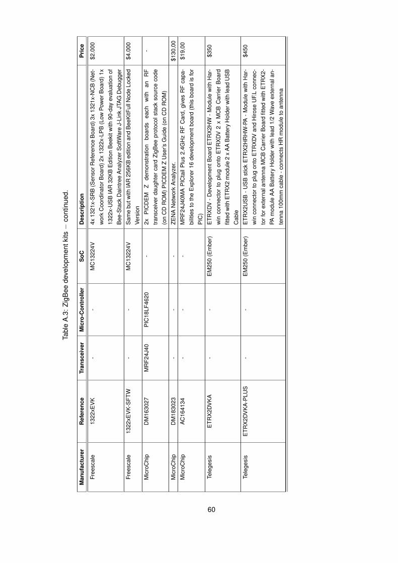
Tabl
eA
.3:
ZigB
eede
velo
pmen
tkits−
cont
inue
d.
Man
ufac
ture
rR
efer
ence
Tran
scei
ver
Mic
ro-C
ontr
olle
rS
oCD
escr
iptio
nP
rice
Free
scal
e13
22xE
VK
--
MC
1322
4V4x
1321
x-S
RB
(Sen
sorR
efer
ence
Boa
rd)3
x13
21x-
NC
B(N
et-
wor
kC
oord
inat
orB
oard
)2x
1322
x-LP
B(L
owPo
wer
Boa
rd)1
x
1322
x-U
SB
IAR
32K
BE
ditio
nB
eeki
twith
90-d
ayev
alua
tion
of
Bee
-Sta
ckD
aint
ree
Ana
lyze
rSof
tWar
eJ-
Link
JTA
GD
ebug
ger
$2.0
00
Free
scal
e13
22xE
VK
-SFT
W-
-M
C13
224V
Sam
ebu
twith
IAR
256K
Bed
ition
and
Bee
KitF
ullN
ode
Lock
ed
Vers
ion
$4.0
00
Mic
roC
hip
DM
1630
27M
RF2
4J40
PIC
18LF
4620
-2x
PIC
DE
MZ
dem
onst
ratio
nbo
ards
each
with
anR
F
trans
ceiv
erda
ught
erca
rdZi
gBee
prot
ocol
stac
kso
urce
code
(on
CD
RO
M)P
ICD
EM
ZU
ser’s
Gui
de(o
nC
DR
OM
)
-
Mic
roC
hip
DM
1830
23-
--
ZEN
AN
etw
ork
Ana
lyze
r.$1
30,0
0
Mic
roC
hip
AC
1641
34-
--
MR
F24J
40M
AP
ICta
ilP
lus
2.4G
Hz
RF
Car
d,gi
ves
RF
capa
-
bilit
ies
toth
eE
xplo
rer
16de
velo
pmen
tboa
rd(th
isbo
ard
isfo
r
PIC
)
$19,
00
Tele
gesi
sE
TRX
2DV
KA
--
EM
250
(Em
ber)
ETR
XD
V-D
evel
opm
entB
oard
ETR
X2H
W-M
odul
ew
ithH
ar-
win
conn
ecto
rto
plug
onto
ETR
XD
V2
xM
CB
Car
rier
Boa
rd
fitte
dw
ithE
TRX
2m
odul
e2
xA
AB
atte
ryH
olde
rwith
lead
US
B
Cab
le
$350
Tele
gesi
sE
TRX
2DV
KA
-PLU
S-
-E
M25
0(E
mbe
r)E
TRX
2US
B-
US
Bst
ick
ETR
X2H
RH
W-P
A-
Mod
ule
with
Har
-
win
conn
ecto
rto
plug
onto
ETR
XD
Van
dH
irose
UF.
Lco
nnec
-
torf
orex
tern
alan
tenn
aM
CB
Car
rierB
oard
fitte
dw
ithE
TRX
2-
PAm
odul
eA
AB
atte
ryH
olde
rwith
lead
1/2
Wav
eex
tern
alan
-
tenn
a10
0mm
cabl
e-c
onne
cts
HR
mod
ule
toan
tenn
a
$450
60

Tabl
eA
.4:
ZigB
eem
odul
esan
dth
eirf
eatu
res.
Man
ufac
ture
rR
efer
ence
Tran
scei
ver
Mic
ro-C
ontr
olle
rS
oCD
escr
iptio
nP
rice
UB
EC
U-F
orce
UZ2
400
--
Boa
rdw
ithP
CB
ante
nna.
Giv
esS
PIa
cces
sto
trans
ceiv
er.T
xPo
wer
of+0
dbm
-
UB
EC
U-P
ower
500
--
Equ
alto
prev
ious
buth
asam
plifi
erth
atbo
osts
sign
alto
+10d
bm-
UB
EC
U-P
ower
1000
--
Equ
alto
prev
ious
but
ampl
ifies
to+2
2db
man
dha
sS
MA
ante
nna
conn
ecto
r.
-
Mes
hNet
ics
MN
ZB-2
4-B
0AT
86R
F230
ATM
ega1
281v
-B
oard
with
Bal
ance
dR
FO
utpu
tbut
noan
tenn
a.Tx
Pow
erof
+3db
m
128k
Bs
Flas
h,8k
Bs
RA
Min
apa
ckag
e13
.5x1
8.8m
m
$23
Mes
hNet
ics
MN
ZB-2
4-A
2-
Boa
rdw
ithD
ualC
hip
Ant
enna
.Tx
Pow
erof
+3db
m12
8kB
sFl
ash,
8kB
sR
AM
ina
pack
age
13.5
x24.
0mm
$26
Mes
hNet
ics
MN
ZB-A
24-U
FL-
Am
plifi
edbo
ard
with
U.F
LA
nten
naC
onne
ctor
.Tx
Pow
erof
+20b
dm
128k
Bs
Flas
h,8k
Bs
RA
Min
apa
ckag
e38
.0x1
3.5x
2.0m
m
$36
Oki
sem
iO
KI-Z
NE
DM
L706
5M
L67Q
4061
-Fl
exib
lePo
wer
Sup
ply,
switc
hes,
tri-a
xis
ME
Ms
acce
lero
met
er,p
hoto
and
tem
pera
ture
sens
ors,
thre
ele
ds,
RS
-232
,LC
D,R
adio
conn
ec-
tors
.12
8kB
sfla
shan
d16
kBs
RA
M.
The
MC
Uis
aA
RM
7TD
MI
$80
Jenn
icJN
5139
-xxx
-M00
/01/
03-
-JN
5139
Boa
rdw
ithan
inte
grat
edan
tenn
a(M
00),
SM
Aco
nnec
tor
(M01
)or
U.F
Lco
nnec
tor(
M03
).Tx
Pow
er:
+2.5
dbm
.S
ize:
18x3
0mm
$30
Jenn
icJN
5139
-xxx
-M02
/04
--
Equ
alto
prev
ious
buth
asam
plifi
er.
TxPo
wer
of+1
9dbm
.M
02ha
s
SM
Aco
nnec
tor.
M04
has
uFIc
onne
ctor
$30
Hel
icom
mIP
-Lin
k122
0-21
33C
C24
20C
8051
F121
-Tx
Pow
erof
+10d
bm.R
S23
2/R
S48
5In
terfa
ceZi
gBee
-Com
plia
ntIP
-
Net
netw
orki
ngfir
mw
are.
$58
Hel
icom
mIP
-Lin
k122
1-20
34C
8051
F133
-E
qual
topr
evio
usbu
tTx
Pow
erof
+0db
m
Hel
icom
mIP
-Lin
k122
1-21
34-
Equ
alto
prev
ious
butT
xPo
wer
of+1
0dbm
.$4
5IP
-Lin
k122
1-21
64IP
-Lin
k122
1-21
64ha
sex
tern
alan
tenn
aco
nnec
tor.
Hel
icom
mIP
-Lin
k122
1-22
64-
Equ
alto
prev
ious
but
TxPo
wer
of+1
8dbm
.H
asex
tern
alan
tenn
a
conn
ecto
r
-
Dig
iX
B24
-Z7C
IT-0
04M
C13
192
MC
9S08
GT6
0-
Xbe
elo
wpo
wer
plat
form
with
+1db
mof
TxPo
wer
with
chip
ante
nna
$21
Dig
iX
B24
-Z7W
IT-0
04-
--
The
sam
ebu
twith
anin
tegr
ated
wire
ante
nna
$21
Dig
iX
B24
-Z7U
IT-0
04-
--
The
sam
ebu
twith
anw
/U.F
Lco
nnec
tor
$21
Dig
iX
B24
-Z7S
IT-0
04-
--
The
sam
ebu
twith
aR
PS
MA
conn
ecto
r$2
4
Con
tinue
son
next
page
61
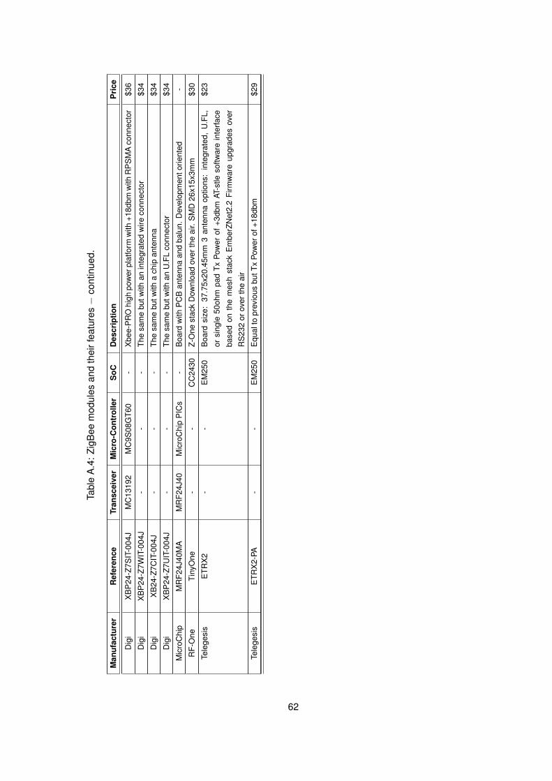
Tabl
eA
.4:
ZigB
eem
odul
esan
dth
eirf
eatu
res−
cont
inue
d.
Man
ufac
ture
rR
efer
ence
Tran
scei
ver
Mic
ro-C
ontr
olle
rS
oCD
escr
iptio
nP
rice
Dig
iX
BP
24-Z
7SIT
-004
JM
C13
192
MC
9S08
GT6
0-
Xbe
e-P
RO
high
pow
erpl
atfo
rmw
ith+1
8dbm
with
RP
SM
Aco
nnec
tor
$36
Dig
iX
BP
24-Z
7WIT
-004
J-
--
The
sam
ebu
twith
anin
tegr
ated
wire
conn
ecto
r$3
4
Dig
iX
B24
-Z7C
IT-0
04J
--
-Th
esa
me
butw
itha
chip
ante
nna
$34
Dig
iX
BP
24-Z
7UIT
-004
J-
--
The
sam
ebu
twith
anU
.FL
conn
ecto
r$3
4
Mic
roC
hip
MR
F24J
40M
AM
RF2
4J40
Mic
roC
hip
PIC
s-
Boa
rdw
ithP
CB
ante
nna
and
balu
n.D
evel
opm
ento
rient
ed-
RF-
One
Tiny
One
--
CC
2430
Z-O
nest
ack
Dow
nloa
dov
erth
eai
r.S
MD
26x1
5x3m
m$3
0
Tele
gesi
sE
TRX
2-
-E
M25
0B
oard
size
:37
.75x
20.4
5mm
3an
tenn
aop
tions
:in
tegr
ated
,U
.FL,
orsi
ngle
50oh
mpa
dTx
Pow
erof
+3db
mAT
-stle
softw
are
inte
rface
base
don
the
mes
hst
ack
Em
berZ
Net
2.2
Firm
war
eup
grad
esov
er
RS
232
orov
erth
eai
r
$23
Tele
gesi
sE
TRX
2-PA
--
EM
250
Equ
alto
prev
ious
butT
xPo
wer
of+1
8dbm
$29
62

Appendix B
Ni-MH and Li-ion batteries
The ZigBee module developed in this work is powered by the electric grid and rechargeable
batteries. The batteries ensure uninterrupted operation in case of a power failure. We considered
rechargeable batteries because the module can recharge them, prolonging their lifetime beyond
that achievable with disposable batteries. This choice also reduces battery costs while being more
environment friendly.
This appendix describes the study made to better understand two types of batteries − Ni-
MH or Lithium-Ion (Li-ion) − and how to charge them. It first describes this batteries strengths,
weaknesses and best charging methods and then concludes over the best solution for this work.
Ni-MH and Li-ion were the only two battery types considered due to their high portability when
compared to other battery types [49].
B.1 Ni-MH batteries
Ni-MH batteries, have a good energy density, are cheap and widely available, are capable of
providing great peak currents and have a moderate self-discharge rate with little memory effect.
Their lifetime is prolonged if used in applications where they get shallow discharge cycles, in fact,
deep discharge cycles tend to degrade their performance. Load currents should be in the order of
20% to 50% of the battery’s rated capacity. And temperatures cannot go above 50◦. They shall also
get periodic (once every three months) full discharges to prevent crystalline formation and mitigate
the little memory effect they suffer.
The ideal method of charging a Ni-MH battery, requires a MCU to monitor the battery’s state
and control the current applied to charge it. This method fully charges a fully discharged battery and
assumes each battery (a single 1.2V cell) is individually charged and monitored. The method con-
sists of five stages, sequentially applied to the battery, where the charging current is a percentage
of the battery’s rated capacity C:
1. Pre-Charge: to prevent damaging from fast charging, a battery that is depleted is charged atabout 0.1C mA until its voltage reaches 1V 1.
1Batteries should not be permitted to go under 1V , it negatively affects their performance and lifetime.
63

2. Condition Tests: the internal resistance of the battery shall be measured in order to avoidcharging worn-out or even damaged batteries.
3. Fast Charge: battery is charged with a current greater than 0.5C mA but less than 1C mA.A few minutes (aprox. 15 minutes) after this charging stage start, the battery voltage andtemperature must be sampled every few seconds. The battery is considered to be chargedif:
- the battery voltage falls about 5 to 10 mV2;- the battery voltage stays at the same value for more than 20 minutes;- the battery temperature has a rising rate (dT/dt) of about 1◦ to 2◦ Celsius per minute;
The following conditions shall never occur:
- Battery voltage higher than 1.75V .- Battery temperature higher than 50◦ Celsius.- Charging time higher than 90 minutes, if charging began at highest rate (1C mA).
4. Top-Off Charge: charge at 25% of the rapid charge current is applied for about half the timespent in the fast charge stage, to ensure full charge3.
5. Maintenance Charge: until the battery is used, a charge at 0.1C mA should be appliedfor periods of 16hours, each time the voltage of the battery goes below 1.3V . This stagecounters the battery’s self-discharge rate.
B.2 Li-ion batteries
Li-ion batteries have a higher energy density than Ni-MH batteries, have no memory effect,
have low self-discharge, are environment friendly and do not require periodic cycling4 to extend its
lifetime. Li-ion batteries do not require any maintenance, but capacity is lost with ageing. A battery
typically lasts two to three years, although capacity loss is noticeable after one year.
Li-ion batteries are intolerant to incorrect charging, discharging and temperature abuses. Be-
cause of this their only sold in the form of a battery pack, in which an electronic protection circuit is
present to prevent over-discharging, increase of internal pressure and excessive internal tempera-
ture. This makes them more expensive and not so available as Ni-MH batteries.
A Li-ion battery is charged at a fixed voltage5, with the current applied limited to the battery’s
maximum capacity C. This charging voltage threshold is a characteristic of the Li-ion battery pack.
It takes about three hours to completely charge a Li-ion battery pack, in the mentioned conditions.
Higher current rates do not accelerate the process by much, in fact, they tend to produce not
fully charged batteries. The charging process ends when the battery pack’s voltage reaches the
threshold voltage. During charge the battery pack shall not heat, if that happens the battery pack
is damaged.
After the battery pack has been considered charged, its open-voltage voltage shall be mon-
itored for a few minutes. If it does not hold itself at the threshold value, the charging shall be2This method is commonly referred to, by −δV .3If the temperature or voltage maximum values are reached before this stage’s timer ends, the charging shall be
stopped.4One cycle refers to a full discharge followed by a full charge.5This threshold voltage has a tolerance of only ±0.05V , so the charger circuit must be very precise.
64

restarted. When the battery pack is fully charged (at its threshold voltage level) no intermittent,
trickle or any kind of timed charging shall be applied, since Li-ion cells are unable to absorb over-
charge.
In conclusion, although Li-ion batteries charging is conceptually more simple, it becomes com-
plex to implement, due to the high intolerance Li-ion batteries have to charging imperfections. In
contrast, Ni-MH batteries are much more tolerant. Therefore, Ni-MH batteries were chosen since
they are more robust to charging, are more cheaper and are more commercially available.
As detailed in B.1 the ideal Ni-MH battery charger needs circuitry for voltage and resistance
monitoring, as well as dynamic current control. Such circuitry requires a considerable amount of
PCB area and increases the total module’s cost. So, a simpler charging circuit is required.
The devised charging circuit (see section 3.2.2) implements a method similar to the one de-
scribed in the maintenance stage (B.1). As the power grid will be available for the majority of time,
batteries will be always fully charged. During the temporary duration of a power outage, very low
current is drained by the module (see section 3.2.2) and so a maintenance charge is enough to
counter the lost charge and fully charge the batteries. However, in the prolonged absence of power
from the electric grid, batteries will lose a considerable amount of charge and the maintenance
charge will charge them in a not ideal way. In this case, batteries lifetime is expected to shorten a
little.
65

66

Appendix C
PCB Project Dossier
This appendix contains information for PCB manufacturing and assembly. The module imple-
mented on a four layers PCB with 1 millimetre thickness. Outer layers are used for signal routing
and inner layers for ground and power planes. Components are mounted on the upper layer with
the ground plane immediately below them.
The dossier includes manufacturing information in extended Gerber (RS-274X) files for artwork
and an excellon1 file with tool listing embedded, for drills tooling. Assembly information for compo-
nents placement and acquisition is also included, as well as, the layout for a panel stencil containing
six modules. The electrical circuit is also present.
67

C.1 PCB Layout
The electrical connections (power and signal), for the 4-layers used, are illustrated in figure C.1.
Figure C.2 shows the solder and solder mask patterns required. Figure C.3 concludes with drill
information (sizes and location) and PCB labelling.
(a) Layer TOP (positive). (b) Layer BOTTOM (positive).
(c) Layer GND (negative). (d) Layer PWR (negative).
Figure C.1: PCB layers − Electrical connections and components.
68
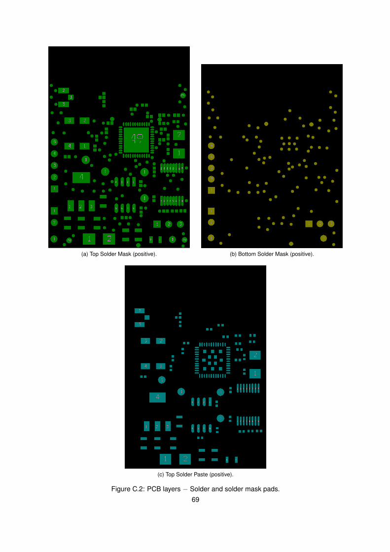
(a) Top Solder Mask (positive). (b) Bottom Solder Mask (positive).
(c) Top Solder Paste (positive).
Figure C.2: PCB layers − Solder and solder mask pads.
69

(a) Mechanical Drawing (values in mils). (b) Drill Drawing.
(c) Top Silkscreen.
Figure C.3: PCB layers − Drills and component labels.
70

C.2 Assembly
The BOM is provided for two distinct suppliers (tables C.1 and C.2), it includes prices and
minimum quantities for both prototyping and production assembly. The components manufacturer
and design references, as well as their values, are available in table C.3. This section ends with
the PCB components placement information in figure C.4.
C.2.1 Bill of Materials (BOM)
Table C.1: Bill of Materials (BOM) − Supplier: Digikey
Item QuantitySupplier Cost (C) Quantity Cost (C) Quantity
DigiKeyPer Unit Minimum Per Unit Minimum
(prototype) (production)
1 3 445-1363 0.196 10 0.031 2,0002 8 587-1229 0.056 10 0.009 10,0003 2 399-3027 0.020 10 0.005 10,0004 1 490-4923 0.048 10 0.007 10,0005 1 490-1284 0.019 10 0.002 10,0006 1 587-1231 0.037 10 0.006 10,0007 2 490-1280 0.019 10 0.003 10,0008 2 399-1038 0.017 10 0.003 10,0009 1 587-1453 0.224 10 0.035 10,000
10 1 490-3103 0.053 10 0.009 10,00011 1 S1BB-FDICT 0.420 1 0.050 3,00012 1 H9161-ND 1.140 1 0.390 2,50013 2 WM6502 0.240 1 - -14 1 WM6504 0.320 1 - -15 1 - - - - -16 1 WM6503 0.280 1 - -17 1 PCD1933CT 0.060 1 0.024 10,00018 1 445-1471 0.120 1 0.035 10,00019 1 PCD1926CT 0.060 1 0.024 10,00020 1 311-124CRCT 0.063 10 0.004 5,00021 1 311-158CRCT 0.063 10 0.004 5,00022 1 RHM5.1ARCT 0.028 10 0.003 10,00023 2 RHM100KJCT 0.063 10 0.003 10,00024 1 311-56.0KLRCT 0.057 10 0.002 10,00025 1 311-43.0KLRCT 0.057 10 0.002 10,00026 4 - - - - -27 1 296-17598 0.540 1 0.190 2,50028 1 M25P40-VMN3TP/XCT 2.030 1 0.960 2,50029 1 MAX3319ECAE+ 4.650 1 0.670 1,00030 1 296-21950 7.690 1 4.400 1,00031 1 644-1044 0.450 1 0.250 1,00032 1 535-9166 0.400 1 0.210 3,000
71
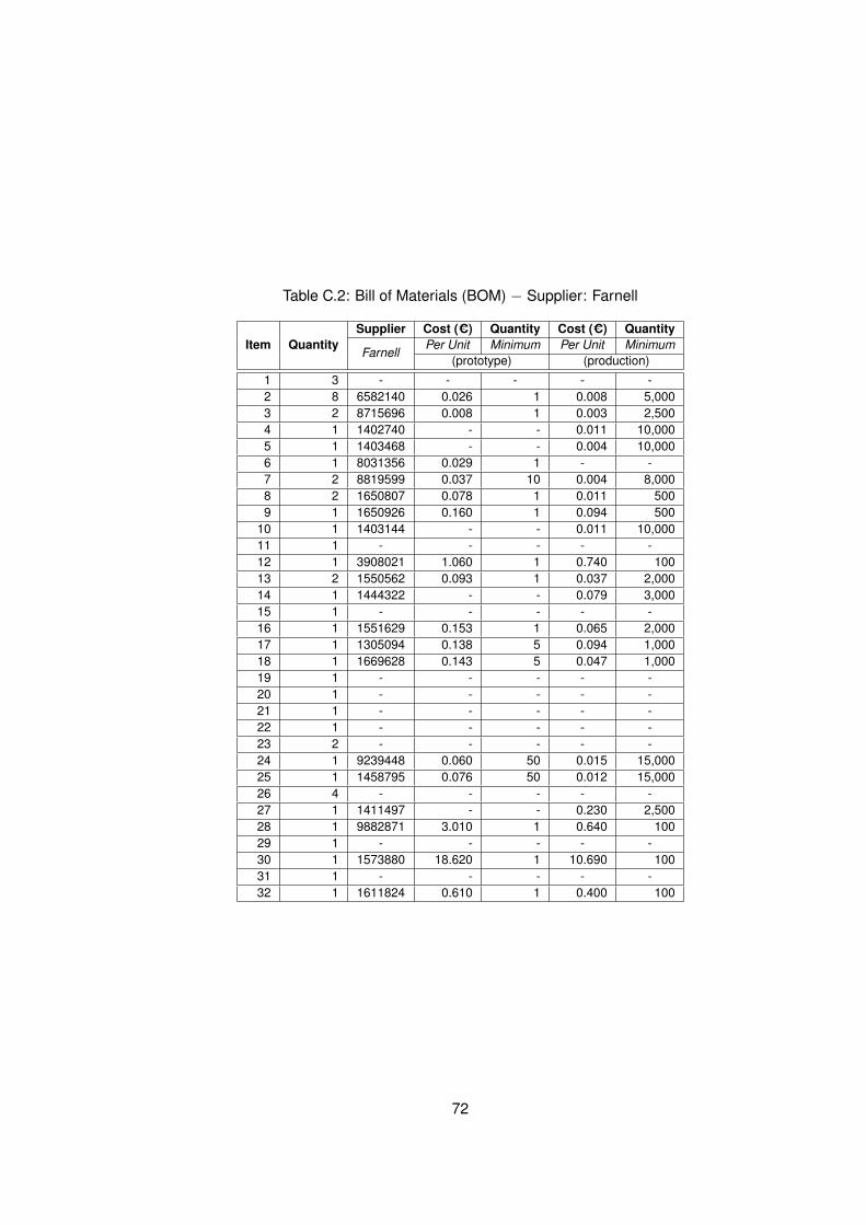
Table C.2: Bill of Materials (BOM) − Supplier: Farnell
Item QuantitySupplier Cost (C) Quantity Cost (C) Quantity
FarnellPer Unit Minimum Per Unit Minimum
(prototype) (production)
1 3 - - - - -2 8 6582140 0.026 1 0.008 5,0003 2 8715696 0.008 1 0.003 2,5004 1 1402740 - - 0.011 10,0005 1 1403468 - - 0.004 10,0006 1 8031356 0.029 1 - -7 2 8819599 0.037 10 0.004 8,0008 2 1650807 0.078 1 0.011 5009 1 1650926 0.160 1 0.094 500
10 1 1403144 - - 0.011 10,00011 1 - - - - -12 1 3908021 1.060 1 0.740 10013 2 1550562 0.093 1 0.037 2,00014 1 1444322 - - 0.079 3,00015 1 - - - - -16 1 1551629 0.153 1 0.065 2,00017 1 1305094 0.138 5 0.094 1,00018 1 1669628 0.143 5 0.047 1,00019 1 - - - - -20 1 - - - - -21 1 - - - - -22 1 - - - - -23 2 - - - - -24 1 9239448 0.060 50 0.015 15,00025 1 1458795 0.076 50 0.012 15,00026 4 - - - - -27 1 1411497 - - 0.230 2,50028 1 9882871 3.010 1 0.640 10029 1 - - - - -30 1 1573880 18.620 1 10.690 10031 1 - - - - -32 1 1611824 0.610 1 0.400 100
72

C.2.2 Component References
Table C.3: Component references and values.
Item Quantity Reference Value ManufacRef Manufacturer1 3 C1,C2,C3 10u_6V3_0805 C2012X5R0J106M TDK Corporation
2 8C4,C5,C6,C7,
0u22_0402 JMK105BJ224KV-F Taiyo YudenC8,C10,C11,C14
3 2 C9,C19 100n_0402 C0402C104K8PACTU Kemet4 1 C12 33p_5%_NP0_0402 GCM1555C1H330JZ13D Murata5 1 C13 27p_5%_NP0_0402 GRM1555C1H270JZ01D Murata6 1 C15 1u_0402 JMK105BJ105KV-F Taiyo Yuden7 2 C16,C17 15p_5%_NP0_0402 GRM1555C1H150JZ01D Murata8 2 C18,C20 10n_X7R_0402 C0402C103K4RACTU Kemet9 1 C26 2u2_0402 JMK105BJ225MV-F Taiyo Yuden
10 1 C27 5p6_0402 GJM1555C1H5R6CB01D Murata11 1 D1 1N4002 S1BB-13-F Diodes Inc12 1 JP2 CON_EXT U.FL-R-SMT(01) Hirose Electric Co Ltd
13 2 J1V_EXT_2pin,
22-28-4023 Molex Connector CorpV-_INT_1pin,V+_INT_1pin
14 1 J4 CON_PRG_DBG_5pin 22-28-4043 Molex Connector Corp15 1 J11 IFA_PCB_ANT Made in PCB -16 1 J12 CON_RS232_3pin 22-28-4033 Molex Connector Corp17 1 L1 6n8_0402 ELJ-RF6N8JFB Parasonic - EGG18 1 L2 22n_0402 MLK1005S22NJ TDK Corporation19 1 L3 1n8_0402 ELJ-RF1N8DFB Panasonic - EGG20 1 R1 124R_0805 RC0805FR-07124RL Yageo21 1 R2 158R_0805 RC0805FR-07158RL Yageo22 1 R3 5R_1/8W_0805 MCR10EZPJ5R1 Rohm Semiconductor23 2 R4,R5 100K_0402 MCR01MZPJ104 Rohm Semiconductor24 1 R6 56K_1%_0402 RC0402FR-0756KL Yageo25 1 R7 43K_1%_0402 RC0402FR-0743KL Yageo26 4 TP1,TP2,TP3,TP4 1.7mm Made in PCB -27 1 U1 TLV1117-ADJ TLV1117CDCYR Texas Instruments28 1 U2 M25P40-SO8 M25P40-VMN3TP/X Numonyx/ST Micro29 1 U3 MAX3319-SSOP16 MAX3319ECAE+ Maxim Integrated30 1 U4 CC2430-QLP48 CC2430ZF128RTCR Texas Instruments31 1 Y1 32MHz NX5032GA-32MHz NDK32 1 Y2 32.768KHz ABS25-32.768KHZ-T Abracon Corporation
73

C.2.3 Top Component Placement
Figure C.4: Component Placement.
74

C.2.4 Schematics
The electrical circuit divided in two figures, figure C.5 presents the SoC and its required com-
ponents. Figure C.6 illustrates the power supply, the RS-232 /TTL level translator and the SPI
memory.
75
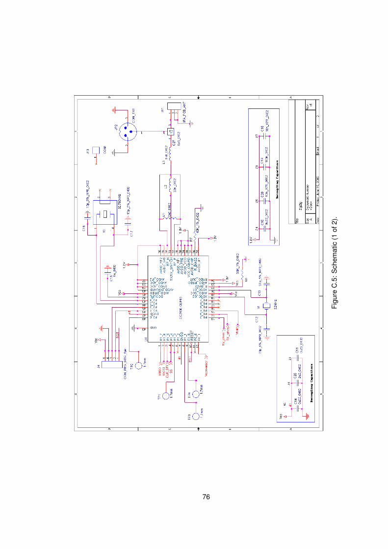
Figu
reC
.5:
Sch
emat
ic(1
of2)
.
76
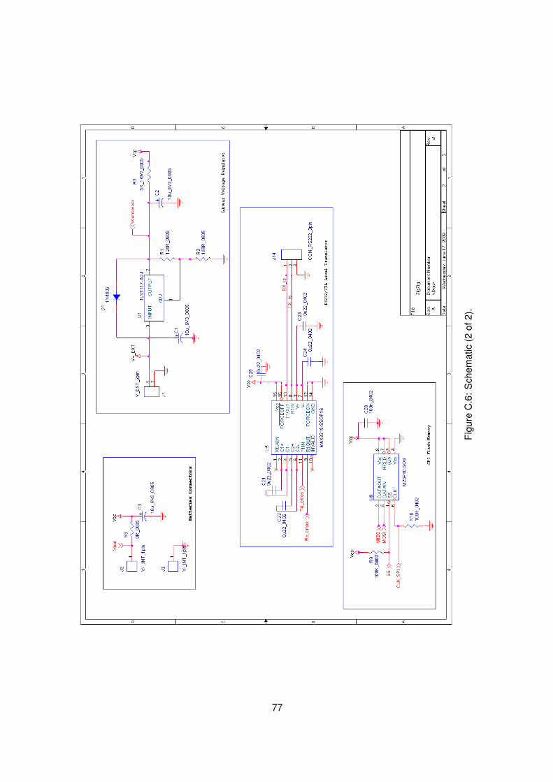
Figu
reC
.6:
Sch
emat
ic(2
of2)
.
77
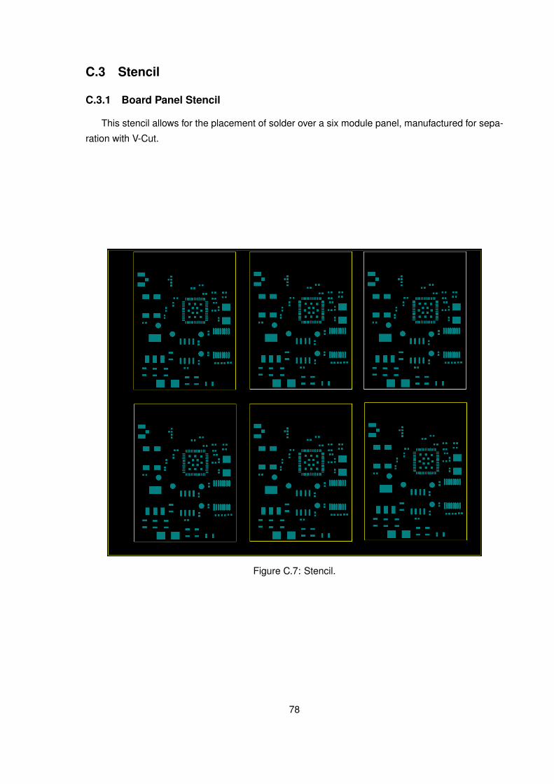
C.3 Stencil
C.3.1 Board Panel Stencil
This stencil allows for the placement of solder over a six module panel, manufactured for sepa-
ration with V-Cut.
Figure C.7: Stencil.
78

Appendix D
Communications in the ZBeeMeRprototype
This appendix presents the ZigBee network frames exchanged by the ZBeeMeR components
in the implemented test network. The exchanged frames validate the association between an
EMSeN and the concentrator (figure D.1), and between an EMSeN and a network extender node
(figure D.2). Also confirmed is the ability of an EMSeN to respond to data requests (figure D.3),
and the procedure an EMSeN follows in sending its first message to the concentrator, when it is
not directly associated with it (figure D.4).
79
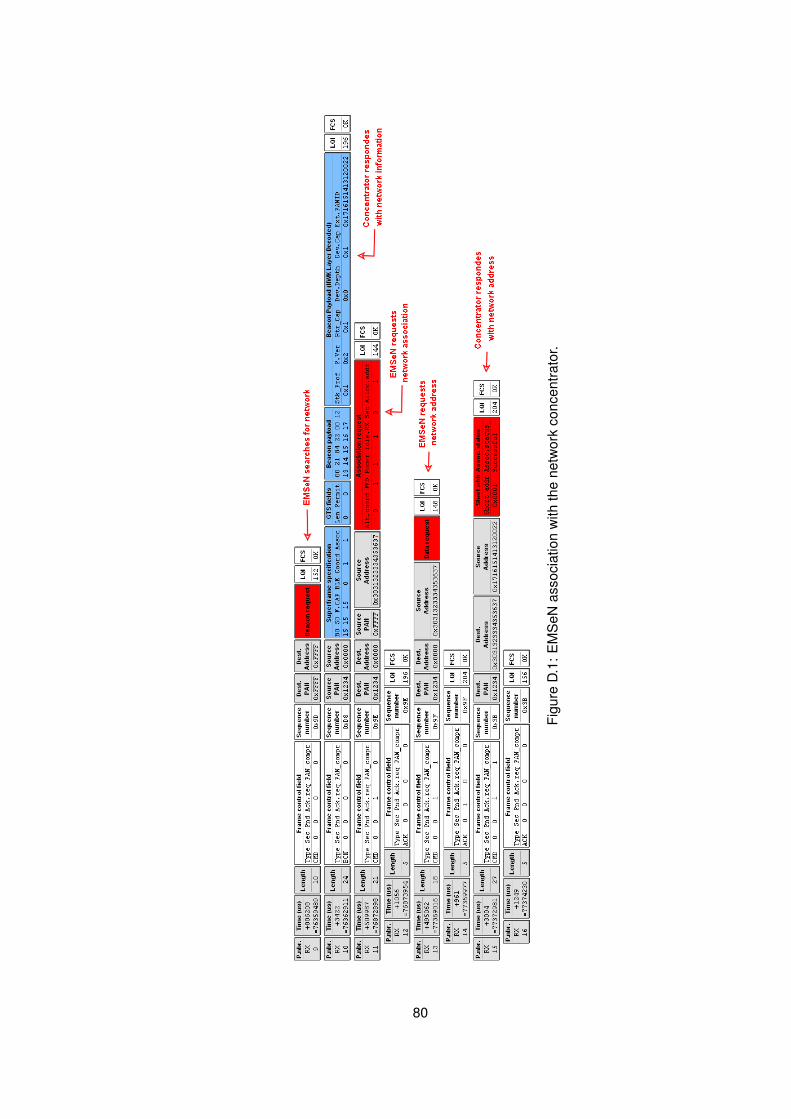
Figu
reD
.1:
EM
SeN
asso
ciat
ion
with
the
netw
ork
conc
entra
tor.
80

Figu
reD
.2:
EM
SeN
asso
ciat
ion
with
ane
twor
kex
tend
erno
de.
81
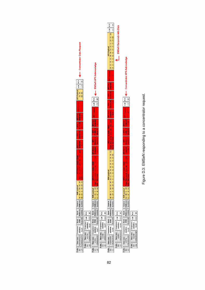
Figu
reD
.3:
EM
SeN
resp
ondi
ngto
aco
ncen
trato
rreq
uest
.
82

Figu
reD
.4:
EM
SeN
perfo
rmin
ga
rout
ere
ques
tand
then
send
ing
data
.
83