Embed Size (px)
Citation preview
C l e a r l y b e t t e r s o u n dZ4MK4/Z8MK4 Zone Mixers
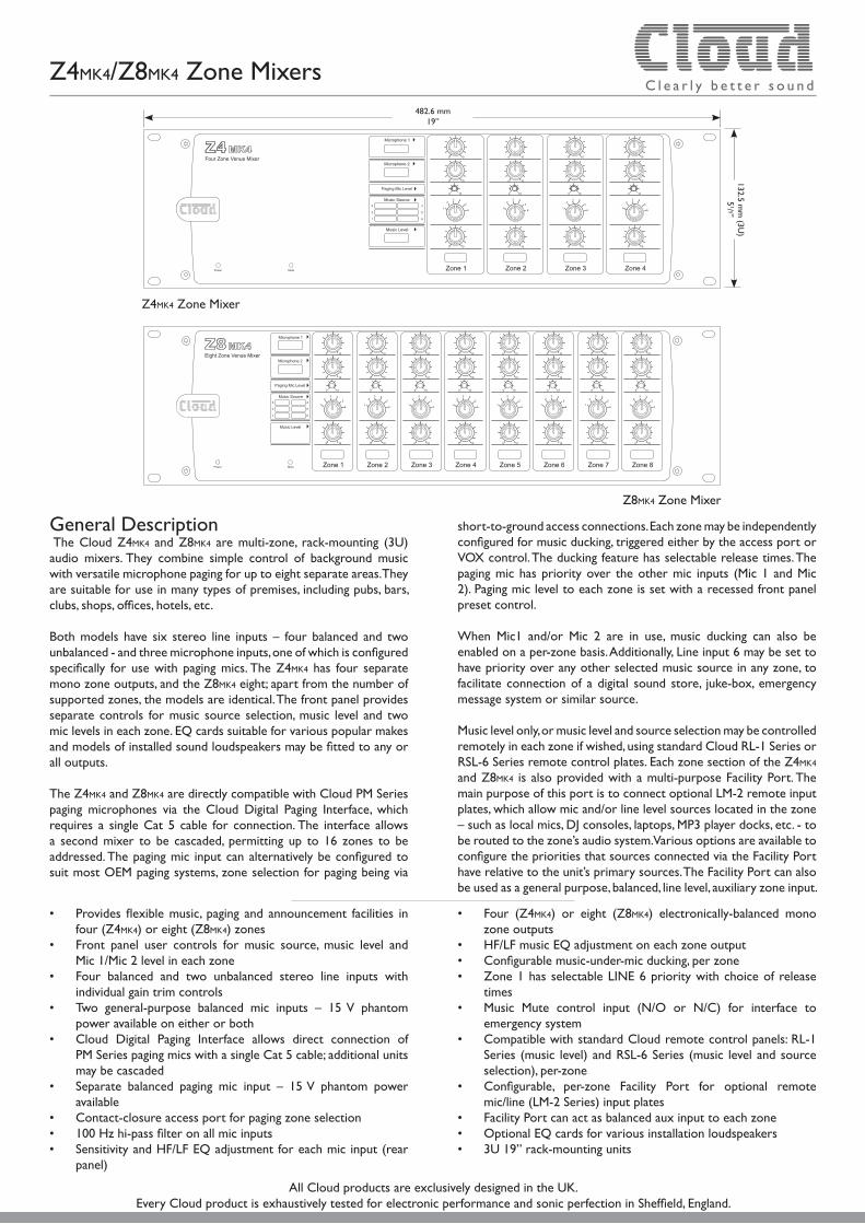
General Description The Cloud Z4MK4 and Z8MK4 are multi-zone, rack-mounting (3U) audio mixers. They combine simple control of background music with versatile microphone paging for up to eight separate areas. They are suitable for use in many types of premises, including pubs, bars, clubs, shops, offices, hotels, etc.
Both models have six stereo line inputs – four balanced and two unbalanced - and three microphone inputs, one of which is configured specifically for use with paging mics. The Z4MK4 has four separate mono zone outputs, and the Z8MK4 eight; apart from the number of supported zones, the models are identical. The front panel provides separate controls for music source selection, music level and two mic levels in each zone. EQ cards suitable for various popular makes and models of installed sound loudspeakers may be fitted to any or all outputs.
The Z4MK4 and Z8MK4 are directly compatible with Cloud PM Series paging microphones via the Cloud Digital Paging Interface, which requires a single Cat 5 cable for connection. The interface allows a second mixer to be cascaded, permitting up to 16 zones to be addressed. The paging mic input can alternatively be configured to suit most OEM paging systems, zone selection for paging being via
short-to-ground access connections. Each zone may be independently configured for music ducking, triggered either by the access port or VOX control. The ducking feature has selectable release times. The paging mic has priority over the other mic inputs (Mic 1 and Mic 2). Paging mic level to each zone is set with a recessed front panel preset control.
When Mic1 and/or Mic 2 are in use, music ducking can also be enabled on a per-zone basis. Additionally, Line input 6 may be set to have priority over any other selected music source in any zone, to facilitate connection of a digital sound store, juke-box, emergency message system or similar source.
Music level only, or music level and source selection may be controlled remotely in each zone if wished, using standard Cloud RL-1 Series or RSL-6 Series remote control plates. Each zone section of the Z4MK4 and Z8MK4 is also provided with a multi-purpose Facility Port. The main purpose of this port is to connect optional LM-2 remote input plates, which allow mic and/or line level sources located in the zone – such as local mics, DJ consoles, laptops, MP3 player docks, etc. - to be routed to the zone’s audio system. Various options are available to configure the priorities that sources connected via the Facility Port have relative to the unit’s primary sources. The Facility Port can also be used as a general purpose, balanced, line level, auxiliary zone input.
• Provides flexible music, paging and announcement facilities in four (Z4MK4) or eight (Z8MK4) zones
• Front panel user controls for music source, music level and Mic 1/Mic 2 level in each zone
• Four balanced and two unbalanced stereo line inputs with individual gain trim controls
• Two general-purpose balanced mic inputs – 15 V phantom power available on either or both
• Cloud Digital Paging Interface allows direct connection of PM Series paging mics with a single Cat 5 cable; additional units may be cascaded
• Separate balanced paging mic input – 15 V phantom power available
• Contact-closure access port for paging zone selection • 100 Hz hi-pass filter on all mic inputs• Sensitivity and HF/LF EQ adjustment for each mic input (rear
panel)
• Four (Z4MK4) or eight (Z8MK4) electronically-balanced mono zone outputs
• HF/LF music EQ adjustment on each zone output• Configurable music-under-mic ducking, per zone• Zone 1 has selectable LINE 6 priority with choice of release
times• Music Mute control input (N/O or N/C) for interface to
emergency system• Compatible with standard Cloud remote control panels: RL-1
Series (music level) and RSL-6 Series (music level and source selection), per-zone
• Configurable, per-zone Facility Port for optional remote mic/line (LM-2 Series) input plates
• Facility Port can act as balanced aux input to each zone • Optional EQ cards for various installation loudspeakers• 3U 19” rack-mounting units
Z4MK4 Zone Mixer
Z8MK4 Zone Mixer
482.6 mm19”
132.5 mm
(3U)
51/ 5”
All Cloud products are exclusively designed in the UK.Every Cloud product is exhaustively tested for electronic performance and sonic perfection in Sheffield, England.
C l e a r l y b e t t e r s o u n d
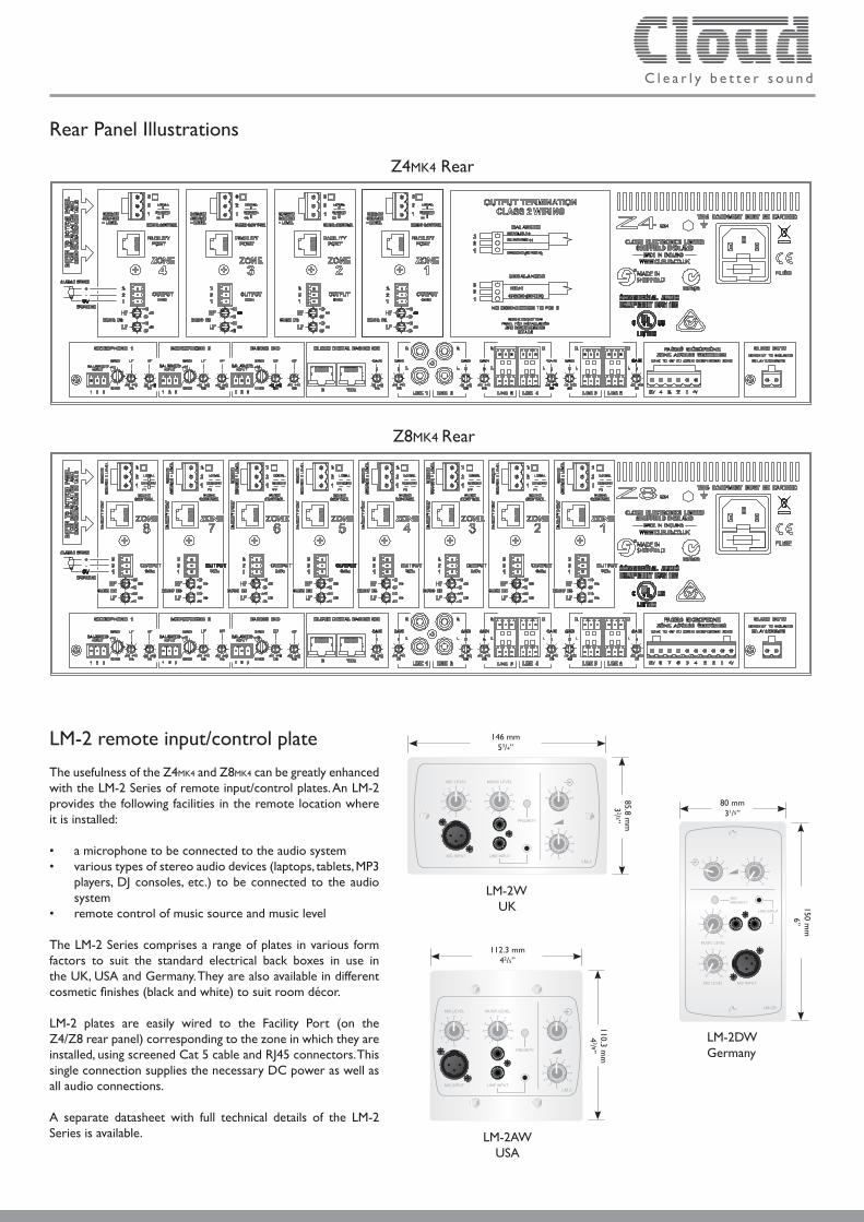
Rear Panel Illustrations
Z8MK4 Rear
Z4MK4 Rear
LM-2 remote input/control plate
The usefulness of the Z4MK4 and Z8MK4 can be greatly enhanced with the LM-2 Series of remote input/control plates. An LM-2 provides the following facilities in the remote location where it is installed:
• a microphone to be connected to the audio system• various types of stereo audio devices (laptops, tablets, MP3 players, DJ consoles, etc.) to be connected to the audio system• remote control of music source and music level
The LM-2 Series comprises a range of plates in various form factors to suit the standard electrical back boxes in use in the UK, USA and Germany. They are also available in different cosmetic finishes (black and white) to suit room décor.
LM-2 plates are easily wired to the Facility Port (on the Z4/Z8 rear panel) corresponding to the zone in which they are installed, using screened Cat 5 cable and RJ45 connectors. This single connection supplies the necessary DC power as well as all audio connections.
A separate datasheet with full technical details of the LM-2 Series is available.
LM-2WUK
1
MIC LEVEL
PRIORITY
1
23 4
5
64 4
5 5
1
2 2
3 3
4
5 6
1
2
3
6 7
9
10
8
7
9
10
8
6 7
9
8
MUSIC LEVEL
LINE INPUTMIC INPUT
10
00
0LM-2
146 mm53/4”
85.8 mm
32/ 5”
LM-2AWUSA
1
MIC LEVEL
PRIORITY
1
23 4
5
64 4
5 5
1
2 2
3 3
4
5 6
1
2
3
6 7
9
10
8
7
9
10
8
6 7
9
8
MUSIC LEVEL
LINE INPUTMIC INPUT
10
00
0 LM-2
112.3 mm42/5”
110.3 mm
43/ 8”
LM-2DWGermany
150 mm
6”
80 mm31/5”
MIC LEVEL
MICPRIORITY
1
23 4
5
6
0
0
0
1
1
1
2
2
2
9
9
9
10
10
10
3
3
3
5
5
5
6
6
6
7
7
7
4
4
4
MUSIC LEVEL
LINE INPUT
MIC INPUT
8
8
8
LM-2D

C l e a r l y b e t t e r s o u n d
System Example - Installation for 3 Zones
The diagram depicts a system where four possible music (or other audio) sources are made available to three or more zones (areas). Only three are shown for clarity.
• Area 1 and Area 3 have remote control plates installed: an RSL-6 (music level and source) in Area 1 and an RL-1 (music level only) in Area 3. These are wired to the Music Control Ports for their respective zone outputs.
• Areas 1 and 2 include LM-2 mic/line input plates, wired to the Facility Ports of Zones 1 and 2 respectively. These would allow both a microphone and a portable stereo music source to be connected in those areas. The LM-2 also provides music source and level control; note that the LM-2 does not require a second connection to the Music Control Port to enable this.
• Area 3 has a Cloud PM series paging microphone, which would be used to originate voice messages to any of the other areas. This uses the Cloud Digital Paging Interface on the Z8MK4, which requires only a single Cat 5 connection. The paging level to Area 3 (if required) would be adjusted on installation to be at a level that does not cause feedback.
ZONE 5
ZONE 3
ZONE 2
ZONE 6
ZONE 8
ZONE 4
ZONE 7
ZONE 1
ZONE 5
ZONE 3
ZONE 2
ZONE 6
ZONE 8
ZONE 4
ZONE 7
ZONE 1
ZONE 5
ZONE 3
ZONE 2
ZONE 6
ZONE 8
ZONE 4
ZONE 7
ZONE 1
OU
TPU
TSM
US
IC C
ON
TRO
L PO
RTS
FAC
ILTY P
OR
TS
INPUT 1
INPUT 6
INPUT 4
INPUT 2
INPUT 3
INPUT 5
MIC 1
MIC 2
PAGING MIC
PAGING ACCESS
CDPM
CD PLAYER
PC
RADIOTUNER
OEM PAGINGMIC SYSTEM
FREEVIEW RECIEVER
AREA 1
AREA 2
AREA 3
POWER AMPLIFIERS
OTHER AREAS
PM PAGING MICROPHONE
RSL-6
LM-2
RL-1
LM-2
LOCAL MICS
Z8MK4
Cat 5
Cat 5
Block Diagram - Z8MK4 (8 zones)
The simplified block diagram above illustrates the basic signal architecture of the Z8MK4. Only the routing and logic for one zone output is shown. The architecture of the Z4MK4 is identical, the only difference being the number of zone outputs.
• An existing building-wide paging system can be connected to the “analogue” paging mic input, and use the contact-closure access connector to page to any zone. The Digital Paging Interface will take priority in the event of simultaneous paging from the two systems.
C l e a r l y b e t t e r s o u n d
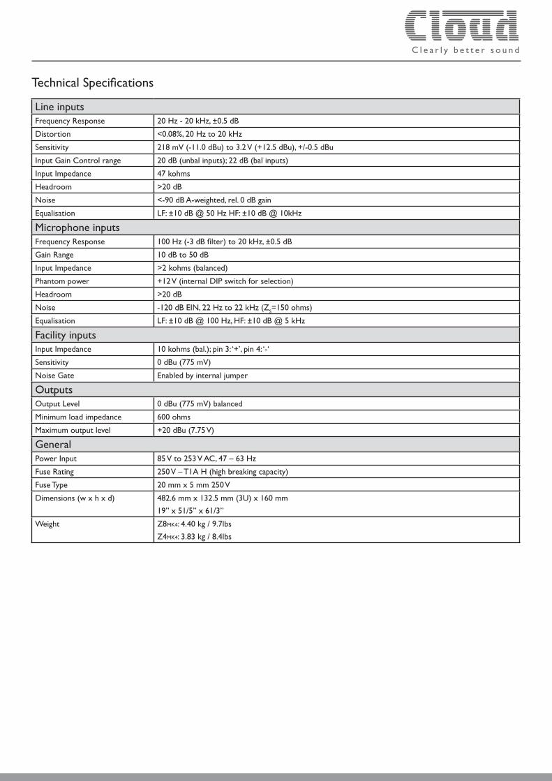
Technical Specifications
Line inputsFrequency Response 20 Hz - 20 kHz, ±0.5 dB
Distortion <0.08%, 20 Hz to 20 kHz
Sensitivity 218 mV (-11.0 dBu) to 3.2 V (+12.5 dBu), +/-0.5 dBu
Input Gain Control range 20 dB (unbal inputs); 22 dB (bal inputs)
Input Impedance 47 kohms
Headroom >20 dB
Noise <-90 dB A-weighted, rel. 0 dB gain
Equalisation LF: ±10 dB @ 50 Hz HF: ±10 dB @ 10kHz
Microphone inputsFrequency Response 100 Hz (-3 dB filter) to 20 kHz, ±0.5 dB
Gain Range 10 dB to 50 dB
Input Impedance >2 kohms (balanced)
Phantom power +12 V (internal DIP switch for selection)
Headroom >20 dB
Noise -120 dB EIN, 22 Hz to 22 kHz (ZS=150 ohms)
Equalisation LF: ±10 dB @ 100 Hz, HF: ±10 dB @ 5 kHz
Facility inputsInput Impedance 10 kohms (bal.); pin 3: ‘+’, pin 4: ‘-‘
Sensitivity 0 dBu (775 mV)
Noise Gate Enabled by internal jumper
OutputsOutput Level 0 dBu (775 mV) balanced
Minimum load impedance 600 ohms
Maximum output level +20 dBu (7.75 V)
GeneralPower Input 85 V to 253 V AC, 47 – 63 Hz
Fuse Rating 250 V – T1A H (high breaking capacity)
Fuse Type 20 mm x 5 mm 250 V
Dimensions (w x h x d) 482.6 mm x 132.5 mm (3U) x 160 mm
19” x 51/5” x 61/3”
Weight Z8MK4: 4.40 kg / 9.7lbs
Z4MK4: 3.83 kg / 8.4lbs

C l e a r l y b e t t e r s o u n d
Performance Graphs
Music Crosstalk
Sweep Trace Line Style Thick Data Axis Comment
1 1 Dot 1 Anlr.Ampl Left Crosstalk, Adjacent Line Inputs2 1 Solid 1 Anlr.Ampl Left Crosstalk Between Outputs
Note that the crosstalk was not measured using bandpass techniques. It is below the noise floor between zone outputs and between line inputs below 1kHz.
-120
+0
-110
-100
-90
-80
-70
-60
-50
-40
-30
-20
-10
dBu
20 20k50 100 200 500 1k 2k 5k 10kHz
Music Frequency Response
-3
+3
-2.5
-2
-1.5
-1
-0.5
-0
+0.5
+1
+1.5
+2
+2.5
dBu
20 20k50 100 200 500 1k 2k 5k 10kHz
Z4MK4/Z8MK4 Music Crosstalk Z4MK4/Z8MK4 Music Output Frequency Response
Architect’s and Engineer’s Specification
The mixer shall be available in two versions, with four or eight electronically balanced mono outputs (zones) on rear panel multipin connectors respectively. Unless otherwise stated, all specifications which follow shall apply to both versions, with the two versions differing only in those facilities specific to the outputs. The mixers shall be equipped with two unbalanced stereo music inputs on phono sockets (RCA jacks), four balanced stereo music inputs on plug-in screw-terminal connectors and three electronically balanced microphone inputs on plug-in screw terminal connectors. All inputs shall be on the rear of the mixer. One of the microphone inputs shall be configured specifically to operate with paging microphones. The music input to each zone and the music level in the zone shall be adjustable by front panel controls. Each zone shall also have its own front panel microphone level controls, one per microphone input. The level control for the paging microphone input shall be of the preset type and recessed behind the panel. It shall be possible to control the level of the music source independently of the microphone levels in each zone.
Each music input shall have a rear panel input gain trim control with a range of at least 20 dB. Two-band equalisation adjustment shall be provided on the rear panel for the music signal in each zone. Two-band equalisation adjustment shall also be available for each microphone input; phantom power shall be available at any or all microphone inputs when selected by internal DIP switch.
It shall be possible to connect a compatible paging microphone to the mixer using a single Cat 5 cable; an RJ45 connector shall be provided for this purpose. The port shall carry audio, zone selection data and power for the microphone. A second RJ45 port shall enable a second mixer to be connected such that microphones able to page a greater number of zones than the mixer can support may be able to do so via the use of the second mixer. The mixer shall be provided with a second method of paging, in the form of a control input to activate the paging microphone input by external contact closure, and route its signal to any or all zones, replacing the music signal while the contacts are closed.
It shall be possible to configure the mixer to perform the following functions: i) detection of a signal on either non-paging microphone input will automatically reduce the music level by 30 dB, ii) detection of a signal on the paging microphone input will automatically route the signal to all zones, iii) one line input will automatically override all others in all zones, even if unselected.
Optional remote control panels shall be available to permit control of i) music level in any zone; ii) music source selection and music level in any mixer channel; it shall be possible to retrofit these to the mixer at any time. The remote control panels shall connect via a rear panel plug-in screw-terminal connector. It shall be possible to disable either the front panel music level or the music level and music source selection controls by moving internal jumpers.
An external control input shall be provided to allow muting of the music source by a fire alarm or other external emergency system via isolated, ‘volt-free’ contacts, and this input shall be configurable to respond to either a short or open external circuit. Front panel LED indication of the muting action shall be provided.
Each zone output shall be provided with an additional balanced input on a multipin connector; this input shall route audio only to its own zone. An optional input plate shall be available to allow the connection of external microphone and line level audio sources at a remote location, and this plate shall connect to the mixer via the multipin connector, which also shall supply DC power and all necessary control interface connections. The remote input plate shall allow the connection of one microphone and one stereo line level input, with individual level controls for each input, and sum the inputs. Controls shall also be provided for music source selection and music level in the zone to which it is connected. It shall be possible to enable the mixer’s music ducking facility from the plate.
The mixer shall accept internal plug-in equaliser cards to permit use with compatible loudspeakers. It shall be possible to fit these in any or all of the zone outputs.
The mixer shall be built in a 3U steel chassis for mounting in a standard 19” rack. The mixer will operate from any AC mains supply voltage between 85 V and 253 V. The mains supply shall be connected via a detachable IEC cable and there shall be a front-panel LED which illuminates when AC mains power is connected. The mixers shall be the Cloud Z4MK4 (four output zones) and the Cloud Z8MK4 (eight output zones); the optional remote control panels shall be the Cloud RL- 1 Series (music level only) and the Cloud RSL-6 Series (music level and source selection). The optional remote input plate shall be the Cloud LM-2.
C l e a r l y b e t t e r s o u n d
Issue_1.0
Cloud Electronics Limited140 Staniforth Road, Sheffield, S9 3HF. England.
Telephone: +44 (0)114 244 7051 Fax: +44 (0)114 242 5462 Web: www.cloud.co.uk E-mail: [email protected]
Cloud Electronics USA2065 Sidewinder Drive, Suite 200, Park City,
Utah 84060. United States of America. Toll Free: 0855 810 0161
Web: www.cloudusa.pro E-mail: [email protected]
E&OE