Embed Size (px)
Citation preview
1
Z-Wave.Me Wall Flush-Mountables Manual ZME_06431: Switch ZME_06433: Dimmer ZME_06436: Motor Control Firmware Version 1.5
1 General Information about Z-‐Wave
Safe: Generally radio systems build a direct link between the transmitter and the receiver. The radio signal is attenuated by every obstacle along its path (in the household e.g. wall, furniture etc). In the worst case the radio system ceases to function. The advantage of the intelligent Z-Wave system is the so-called routing function: All devices of Z-Wave not only act as transmitter or receiver but also simultaneously as “repeater”. Should a direct radio link between the transmitter and the receiver not be possible, communication will be established with the assistance of other devices.
Communicative: Z-Wave is a bidirectional radio system. This means that a signal is not just sent but also a feedback confirming the reception of the signal occurs automatically. The safety of transmission of the Z-Wave radio-bus-technology is comparable with that of a wire-linked bus system. It is likewise possible to determine the switching status by pushing a button: Has the cellar light been definitely switched off? Trouble-‐free: Z-Wave transmits at a regulated frequency band with a frequency of 868 MHz. Every Z-Wave network has its own unique network identification. Therefore, it is possible to operate two or more independently operating networks in a room or home without any interference. Troubles that can be caused by other devices, as is the case in open, non-regulated frequencies (e.g. 433 MHz) are excluded.
Established: Although the Z-Wave technology is new, it has already developed to form a technical standard. Renowned manufacturers from various fields offer solutions and applications that are based on Z-Wave technology and compatible among one another. This makes the system fit for the future and promises further upgrade phases. Further information can be found on www.z-wave.com.
Dynamic: Z-Wave is equipped with a dynamic network structure. Right from the start, the position of the individual Z-Wave device that is supplied with 230 Volts is monitored and automatically updated in the case of changes. As a means of which it is possible to continuously adapt the network to its individual requirements, wholly automatically without the necessity of any programming tasks.
2 Before Installation/Setup Please read carefully the enclosed user manual before installation of the radio-actuator, in order to ensure an error-free functioning. ATTENTION: only authorized technicians under consideration of the country-specific installation guidelines/norms may do works with 230 Volt networks. Prior to the assembly of the product, the voltage network has to be switched off and ensured against re-switching. The product is permitted only for proper use as specified in the user manual. Any kind of guarantee claim has to be forfeited if changes, modifications or painting are undertaken. The product must be checked for damages immediately after unpacking. In the case of damages, the product must not be operated in any case. If a danger-free operation of the equipment cannot be assured, the voltage supply has to be immediately interrupted and the equipment has to be protected from unintended operation.
2
3 Product Description
Switch: This device is designed to switch any kind of 230 V mains connected electrical load (resistive, inductive and reactive). The maximum electrical load is defined in the technical product spec.
Dimmer: This device is designed to dim attached lights. Usage is restricted to incandescent light, high voltage Halogen lamps and any low voltage and Compact Fluorescent Lights (CFL) with resistive or inductive load). The dimmer can’t dim any reactive load, typically for certain switching power supplies or CFLs. Please make sure the right load is connected to the dimmer before operating. Connecting a reactive load may destroy both the load and the dimmer. The maximum electrical load is defined in the technical product spec.
Sun blind Control: The device is designed to control single or double motor sunblind, shutters or electrical gates. The controller turns on a 230 V supply or any other voltage supply to operate the motor and turns off the supply automatically after 1 minute in order to protect the motor. It is possible to adjust the operation time. The maximum electrical load is defined in the technical product spec. Note: The use of Flush-Mountables with equipment that does not comply with the technical standards can cause malfunctioning or damage connected equipments or flush mounted products.
4 Installation The build-in can be controlled both by using clipped-on rockers, as well as wireless wall switch or remote control. The assembly must take place in a voltage-free state by an authorized electrical technician. Turn off the power supply prior to the mounting and confirm the absence of voltage with a 2-pin
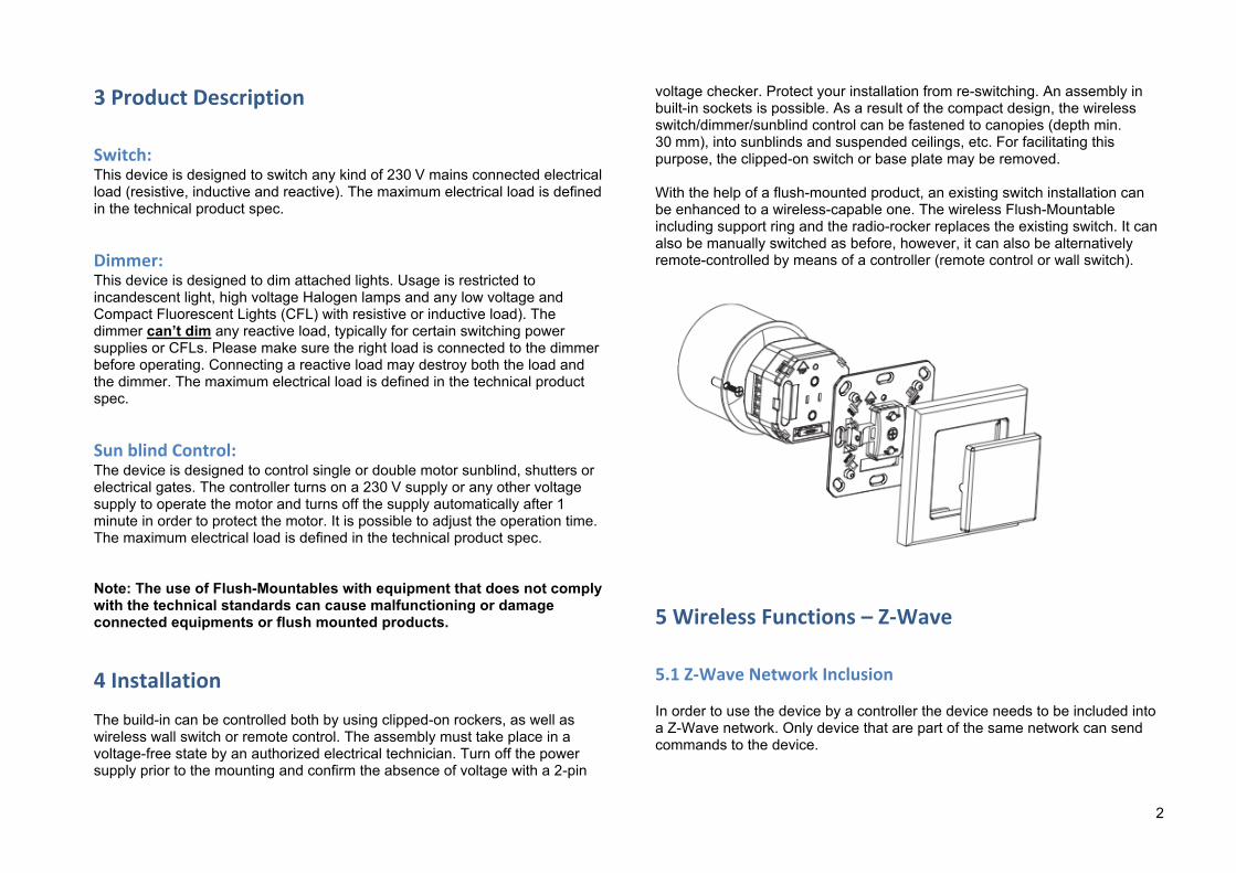
voltage checker. Protect your installation from re-switching. An assembly in built-in sockets is possible. As a result of the compact design, the wireless switch/dimmer/sunblind control can be fastened to canopies (depth min. 30 mm), into sunblinds and suspended ceilings, etc. For facilitating this purpose, the clipped-on switch or base plate may be removed. With the help of a flush-mounted product, an existing switch installation can be enhanced to a wireless-capable one. The wireless Flush-Mountable including support ring and the radio-rocker replaces the existing switch. It can also be manually switched as before, however, it can also be alternatively remote-controlled by means of a controller (remote control or wall switch).
5 Wireless Functions – Z-‐Wave
5.1 Z-‐Wave Network Inclusion In order to use the device by a controller the device needs to be included into a Z-Wave network. Only device that are part of the same network can send commands to the device.
3
1. Follow the instructions on your Z-Wave Primary or Inclusion Controller to include (add) a Z-Wave device
2. Press Up or Down button three times during 1.5 seconds 3. The LED will become green for 3 seconds and then turn off 4. Your device is ready to work!
5.2 Z-‐Wave Network Exclusion ´ In order to remove the device from a Z-Wave network the following steps have to be performed.
1. Follow the instructions on your Z-Wave Primary or Inclusion Controller to exclude (remove) a Z-Wave device
2. Press Up or Down button three times during 1.5 seconds 3. The LED will begin to blink with red and green continuously. 4. Note! All configurations and associations stored in the device are
deleted during Exclusion process 5. Your device can now be removed physically!
Attention: Removing the device from the network means that it is turned back into factory default status.
5.3 Z-‐Wave Associations The Flush-Mountable supports single and double paddle click to control other Z-Wave devices. The relationship between a controller paddle click and an action on a different Z-Wave device is called association. If there are different buttons or different ways to operate a button this may result in different actions. Devices that receive the same command from such an action are referred to as association groups. Refer to your Z-Wave Controller instructions to add devices in these association groups. A PC gateway/controller gives you the most comfortable and powerful way to configure your device. Association groups:
1. Single click or hold control devices in Association group No 1
2. Double click or click-hold control devices in group No 2 3. Devices in Association group No 3 are informed about all device
switch state changes. All groups support up to 8 nodes and 8 (node, channel) pairs.
5.4 Z-‐Wave Configuration Z-Wave products are supposed to work out of the box after inclusion, however certain configuration can adapt the function better to user needs or unlock further enhanced features. Note: Configuration parameters 1…3 and 10…15 are similar for all three devices, switches don’t support configuration 5…9, dimmers don’t support configurations 8…9. IMPORTANT: Controllers may only allow to configure signed values. In order to set values in the range 128…255 for parameters 4, 5 and 6 the value sent in the application shall be the desired value minus 256. For example: to set parameter 4 in Window Blind to 200 s it may be needed to set a value of 200−256=−56. Similar rule applies to parameter 2: to set values in range 32768…65535 use value equal to desired value minus 65536. For example, to set auto switch off period to 10 hours = 36000 s it may be needed to set a value 36000−65536=−29536.
LED mode (parameter No 1, size 1 byte) Set LED indication mode Values: 0 Disabled 1 Show switch/dimmer state / when in motion or inactive (for blinds) 2 Night mode (inverted switch state) 3 Operated by Indicator Command Class (default) 4 Show if not closed (for blinds only)
Automatically switch off after (parameter No 2, size 2 bytes) If not zero, automatically switch off / close blind after a user defined time

4
Values: 0 Disabled (default) 1 – 65535 Switch off / close blind after this time (in s)
What to do on RF off command (parameter No 3, size 1 byte) Defines how to interpret RF Off command. Can be used in conjunction with Auto Off function: Ignore — to switch on the light by motion detectors and switch it off after some amount of time: in case of multiple motion detectors each would try to switch the light off that would break logics; Switch on — to switch on the light on both On and Off paddle press on the remote and switch it off after some amount of time. Button off click will still work (if button operations are not disabled). Values: 0 Switch off (default) 1 Ignore 2 Switch on
Switch on dimming by buttons (parameter No 4, size 1 byte, for switch only) Defines if the switch should change it state to on/off if it is dimmed by buttons Values: 0 No 1 Yes (default)
Ignore Start Level (parameter No 4, size 1 byte, for dimmer only) Defines if the dimmer shall ignore start level in StartLevelChange command despite it is specified or not Values: 0 No 1 Yes (default)
Full close time (parameter No 4, size 1 byte, for motor control only)
Time to go from opened to closed state. Used to estimate the current level. Note that in permanent motion mode the reported value would be closed or opened, while all Basic and Multilevel Set values (1…99, 255) would open except 0 value that would close. Values: 0 keep in permanent motion 1 – 255 in s (default is 60 s)
Restore Switch State after Power Cycle (parameter No 5, size 1 byte, for switch only) Defines if the switch should restore switch state to the last state prior to device power off (power cycle) Values: 0 No 1 Yes (default)
Dimmer speed (parameter No 5, size 1 byte, for dimmer only) Time to dim on button presses and Set command (if it has no duration specified). If not 0, dimming will be done smoothly to preserve bulb life. Values: 0 instantly 1 – 255 in 10 ms units (default is 30, equal to 300 ms)
Full open time (parameter No 5, size 1 byte, for motor control only) Time to go from closed to opened state. Used to estimate the current level. Note that in permanent motion mode the reported value would be closed or opened, while all Basic and Multilevel Set values (1…99, 255) would open except 0 value that would close. Values: 0 keep in permanent motion 1 – 255 in s (default is 60 s)
5
Dimming Long speed (parameter No 6, size 1 byte, for dimmer only) Time to dim on button holds and StartLevelChange command (if it has no duration specified). Values: 1 – 255 in s (default is 3 s)
Node Id of the blocking device (parameter No 6, size 1 byte, for motor control only) Id of the blocking device. Commands from this device would be interpreted not as Open/Close, but as block/unblock. Useful with door opening detector: if the door is open, block the blind not to break shades while they move. Values: 0 disabled (default) 1 – 232 Node Id of the blocking device
Set Maximum Light on “On” click (parameter No 7, size 1 byte, for dimmer only) Defines if the dimmer shall set maximum light level on On command. By default on On command dimmer restores last level. This parameter allows to configure to set maximum level on second On command (if already On) or to always switch on to maximum level. Values: 0 No (default) 1 if already in On state 2 Always
On which command from blocking node to enable the protection (parameter No 7, size 1 byte, for motor control only) Defines which command from blocking device to interpret as closed door and hence, unprotected. Values: 0 on “On” (default)
1 on “Off”
Baby Dimming Time (parameter No 8, size 1 byte, for dimmer only) Time to dim on double click Off button for Baby-Dim function. This function works only if the load is operated by single press and hold button action. If enabled, the device will wait for a click timeout to see if the second click would be pressed. This will introduce a small delay for single click commands, unprotected. Values: 0 off (default) 1 – 255 minutes
Reaction on opposite Button (parameter No 8, size 1 byte, for motor control only) Defines how the device shall react when hitting the opposite direction button when motor is moving Values: 0 Stop (default) 1 Stop and start moving reverse direction
Target Dimming Level for Baby DImming (parameter No 9, size 1 byte, for dimmer only) Target level on which to stop while executing Baby Dimming. Can be 0 to completely switch off the light Values: 0 - 99 dimmer level % (default is 0)
Invert Open and Close relays (parameter No 9, size 1 byte, for motor control only) Allow exchanging open and close relays if blind control is wired to the motor incorrectly Values:
6
0 No (default) 1 Yes
Typical click timeout (parameter No 10, size 1 byte) Typical time used to differentiate click, hold, double and triple clicks Values: 1 – 100 in 10 ms units (default is 50, that is equivalent to 500 ms)
Invert buttons (parameter No 11, size 1 byte) Values: 0 No (default) 1 Yes
Switch by buttons (parameter No 12, size 1 byte) If disabled, the local operations by buttons will not switch the load, but only send commands to On/Off association group. In this mode buttons are not linked with the switch anymore. They can be used separately: buttons to control remote device, switch will operate by RF commands only. Values: 0 No 1 By single press and hold (default) 2 By double press and press-hold
Action on button single press or hold (parameter No 13, size 1 byte) Defines which command should be sent on button single press or hold. Basic commands are sent to Association group. Switch All commands are sent broadcast. Values: 0 Disabled 1 Switch On, Off and dim using Basic Set (default) 2 Switch All On/Off
Action on button double press or hold (parameter No 14, size 1 byte) Defines which command should be sent on button double press or press-hold. Basic commands are sent to Association group. Switch All commands are sent broadcast. If not disabled, the device will wait for a click timeout to see if the second click would be pressed. This will introduce a small delay for single click commands Values: 0 Disabled (don't wait for double click, default) 1 Switch On, Off and dim using Basic Set 2 Switch All On/Off
Send the following Switch All commands (parameter No 15, size 1 byte) Values: 1 Switch All Off only (default) 2 Switch All On only 255 Switch All On and Off
5.5 Z-‐Wave Specific Device Information
5.5.1 Z-‐Wave Device Types Switch:
• Generic: Binary Switch • Specific: Binary Power Switch
Dimmer:
• Generic: Multilevel Switch • Specific: Multilevel Power Switch
Motor Control:
• Generic: Multilevel Switch • Specific: Motor Control Class C
7
5.5.2 Supported Command Classes:
• All Switch (V1) • Association (V2) • Basic (V1) • Binary Switch (V1) (not for dimmer) • Configuration (V1) • Indicator (V1) • Manufacturer Specific (V1) • Multi Channel Association (V2) • Multilevel Switch (V3 for blind, V2 for dimmer, not for switch) • Node Naming and Location (V1) • Protection (V1) • Version (V1)
5.5.3 Controlled Command Classes
• Switch All • Multi Channel • Basic • Multilevel Switch
6 Use – Handling and LED indicator
Switch: Switched on/off by a short press
Dimmer: Short press switches the light on or off. Long pressing the rocker starts dimming the light up or down. Releasing the rocker stops the dimming. The dimmer saves the last dimming state. In case the dimmer switches off (short press) and switches on again (short press) the last dimming state is used.
Sun blind: Moves to upper and lower end points by short pressing the buttons. A short press in the opposite direction can stop the movement. Long press or holding
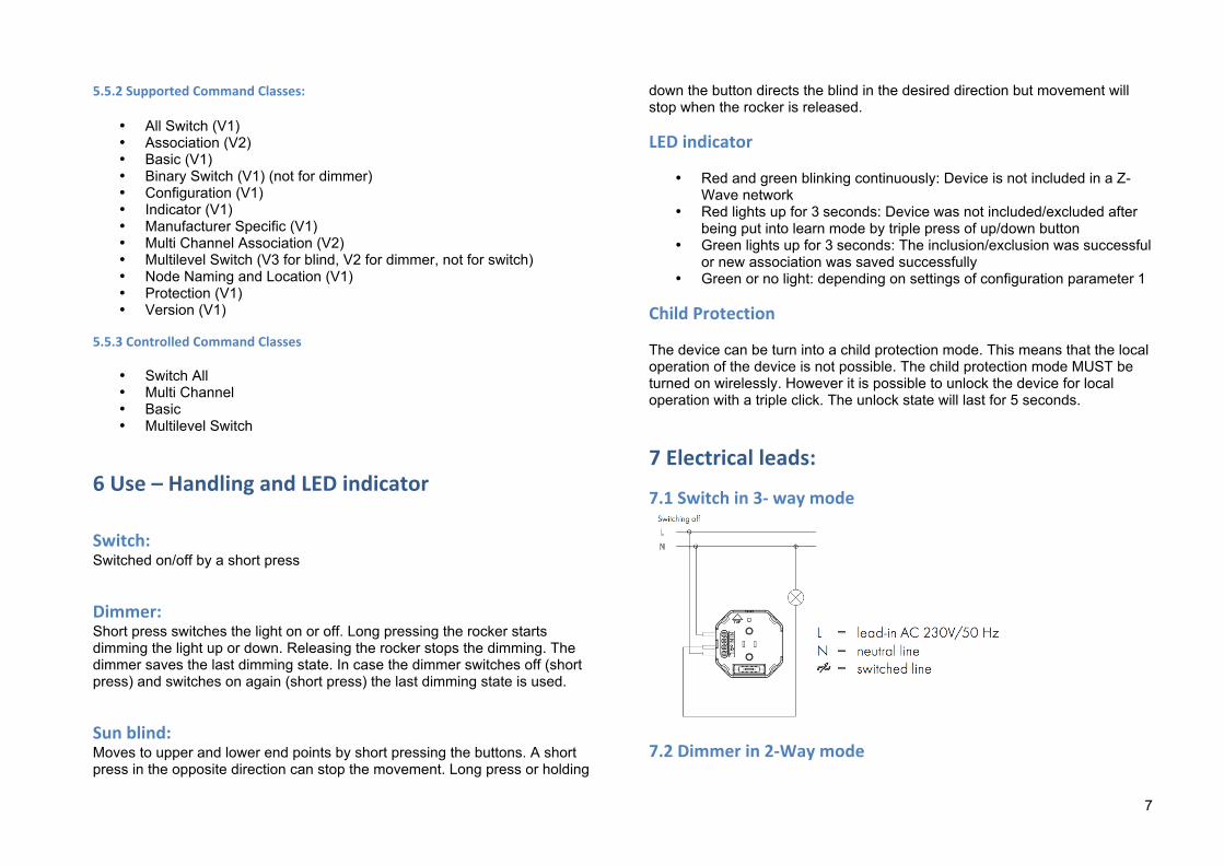
down the button directs the blind in the desired direction but movement will stop when the rocker is released.
LED indicator
• Red and green blinking continuously: Device is not included in a Z-Wave network
• Red lights up for 3 seconds: Device was not included/excluded after being put into learn mode by triple press of up/down button
• Green lights up for 3 seconds: The inclusion/exclusion was successful or new association was saved successfully
• Green or no light: depending on settings of configuration parameter 1
Child Protection The device can be turn into a child protection mode. This means that the local operation of the device is not possible. The child protection mode MUST be turned on wirelessly. However it is possible to unlock the device for local operation with a triple click. The unlock state will last for 5 seconds.
7 Electrical leads:
7.1 Switch in 3-‐ way mode
7.2 Dimmer in 2-‐Way mode

8
7.3 Sun blind control
8 Micro Fuse
Dimmer Flush-‐Mountable: Type: T 1.25 A H (Load 1.25 Ampere, high shutdown capacity), D: 5 mm, L: 20 mm
Switch Flush-‐Mountable: Type: T 10 A H (Load 10 Ampere, high shutdown capacity), D: 5 mm, L: 20 mm
Sun blind Flush-‐Mountable: Type: T 8 A H (Load 8 Ampere, high shutdown capacity), D: 5 mm, L: 20 mm
NOTE: The micro-fuse deals with a backup for the equipment that is specifically designed to this radio-controlled wireless dimmer/switch/sunblind. Please use only this fuse type. This micro-fuse should protect this radio-controlled wireless dimmer/switch/sunblind from overload and short circuits. When using another fuse component there is a danger that the device can be destroyed. A spare fuse is provided in the fuse holder. TROUBLE NOTES: All devices of the system have to be included; therefore, all the articles of the Z-Wave radio system can be combined. The transmission or reception range is up to 100 m in free field and is dependent on the onsite prevailing conditions.
9
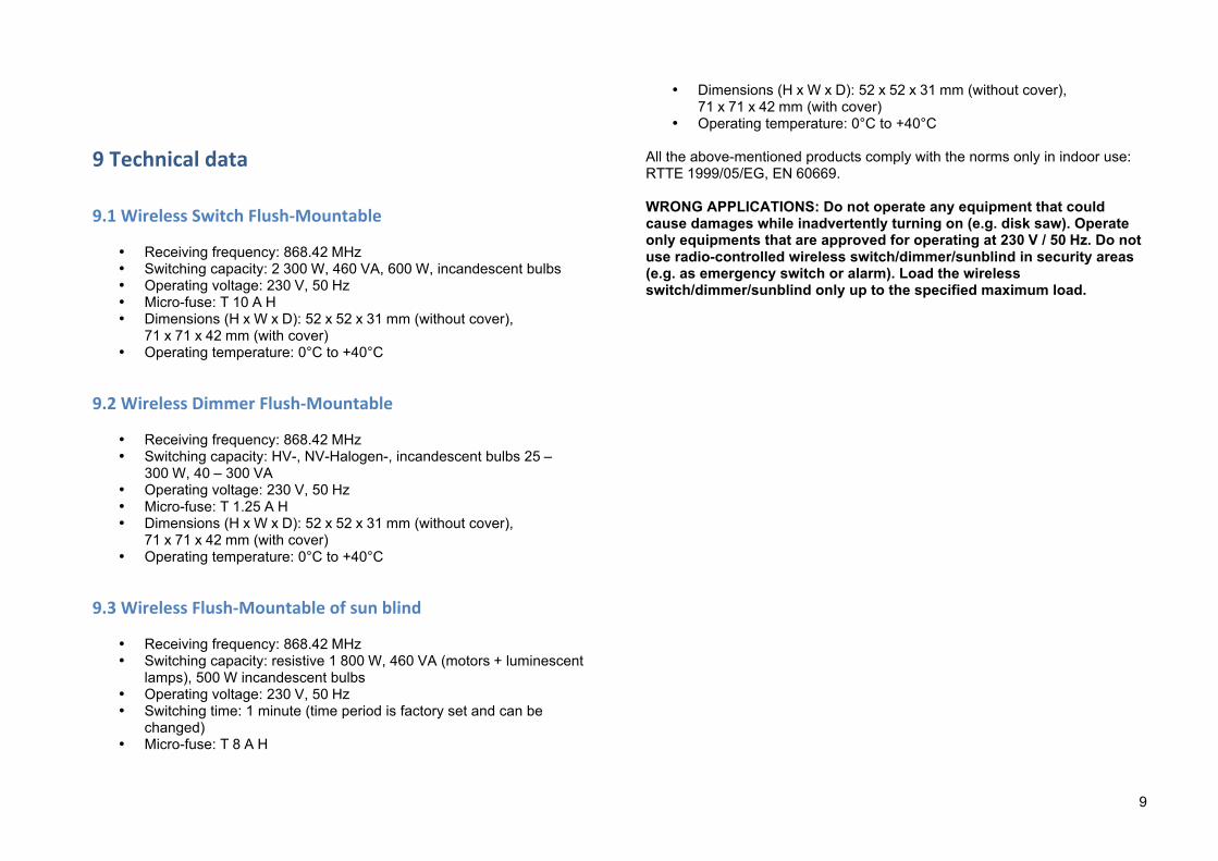
9 Technical data
9.1 Wireless Switch Flush-‐Mountable
• Receiving frequency: 868.42 MHz • Switching capacity: 2 300 W, 460 VA, 600 W, incandescent bulbs • Operating voltage: 230 V, 50 Hz • Micro-fuse: T 10 A H • Dimensions (H x W x D): 52 x 52 x 31 mm (without cover),
71 x 71 x 42 mm (with cover) • Operating temperature: 0°C to +40°C
9.2 Wireless Dimmer Flush-‐Mountable
• Receiving frequency: 868.42 MHz • Switching capacity: HV-, NV-Halogen-, incandescent bulbs 25 –
300 W, 40 – 300 VA • Operating voltage: 230 V, 50 Hz • Micro-fuse: T 1.25 A H • Dimensions (H x W x D): 52 x 52 x 31 mm (without cover),
71 x 71 x 42 mm (with cover) • Operating temperature: 0°C to +40°C
9.3 Wireless Flush-‐Mountable of sun blind
• Receiving frequency: 868.42 MHz • Switching capacity: resistive 1 800 W, 460 VA (motors + luminescent
lamps), 500 W incandescent bulbs • Operating voltage: 230 V, 50 Hz • Switching time: 1 minute (time period is factory set and can be
changed) • Micro-fuse: T 8 A H
• Dimensions (H x W x D): 52 x 52 x 31 mm (without cover), 71 x 71 x 42 mm (with cover)
• Operating temperature: 0°C to +40°C
All the above-mentioned products comply with the norms only in indoor use: RTTE 1999/05/EG, EN 60669. WRONG APPLICATIONS: Do not operate any equipment that could cause damages while inadvertently turning on (e.g. disk saw). Operate only equipments that are approved for operating at 230 V / 50 Hz. Do not use radio-controlled wireless switch/dimmer/sunblind in security areas (e.g. as emergency switch or alarm). Load the wireless switch/dimmer/sunblind only up to the specified maximum load.