Embed Size (px)
Citation preview
15
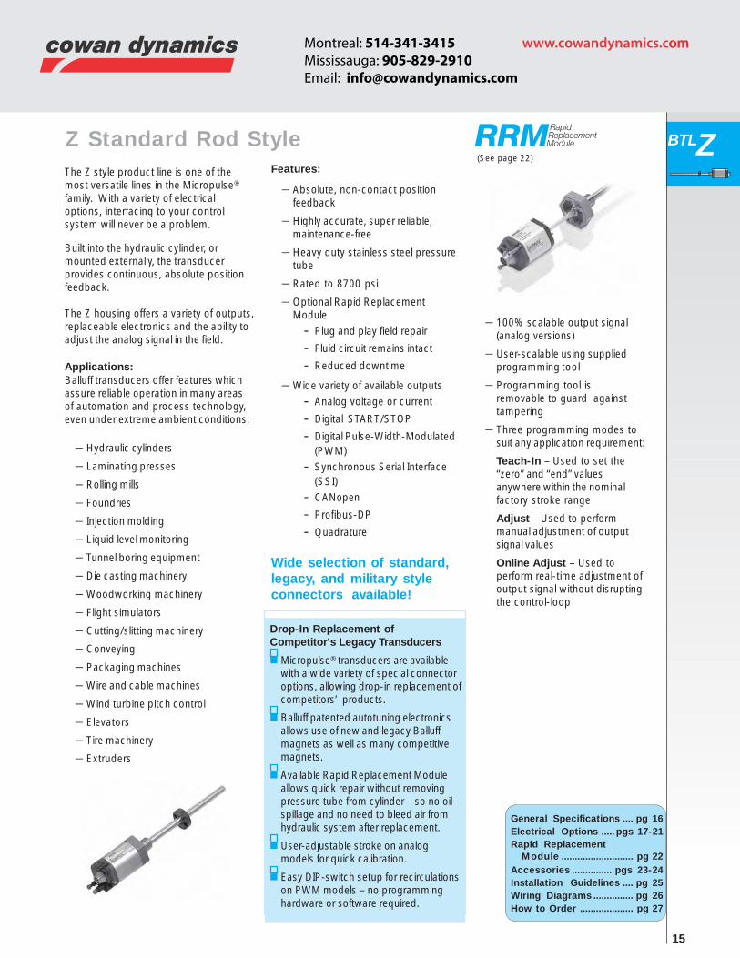
BTLZThe Z style product line is one of themost versatile lines in the Micropulse®
family. With a variety of electricaloptions, interfacing to your controlsystem will never be a problem.
Built into the hydraulic cylinder, ormounted externally, the transducerprovides continuous, absolute positionfeedback.
The Z housing offers a variety of outputs,replaceable electronics and the ability toadjust the analog signal in the field.
Applications:Balluff transducers offer features whichassure reliable operation in many areasof automation and process technology,even under extreme ambient conditions:
– Hydraulic cylinders
– Laminating presses
– Rolling mills
– Foundries
– Injection molding
– Liquid level monitoring
– Tunnel boring equipment
– Die casting machinery
– Woodworking machinery
– Flight simulators
– Cutting/slitting machinery
– Conveying
– Packaging machines
– Wire and cable machines
– Wind turbine pitch control
– Elevators
– Tire machinery
– Extruders
Features:
– Absolute, non-contact positionfeedback
– Highly accurate, super reliable,maintenance-free
– Heavy duty stainless steel pressuretube
– Rated to 8700 psi
– Optional Rapid ReplacementModule
- Plug and play field repair
- Fluid circuit remains intact
- Reduced downtime
– Wide variety of available outputs- Analog voltage or current
- Digital START/STOP
- Digital Pulse-Width-Modulated(PWM)
- Synchronous Serial Interface(SSI)
- CANopen
- Profibus-DP
- Quadrature
General Specifications .... pg 16Electrical Options ..... pgs 17-21Rapid Replacement
Module ........................... pg 22Accessories ............... pgs 23-24Installation Guidelines .... pg 25Wiring Diagrams ............... pg 26How to Order .................... pg 27
Drop-In Replacement ofCompetitor's Legacy Transducers
Micropulse® transducers are availablewith a wide variety of special connectoroptions, allowing drop-in replacement ofcompetitors’ products.
Balluff patented autotuning electronicsallows use of new and legacy Balluffmagnets as well as many competitivemagnets.
Available Rapid Replacement Moduleallows quick repair without removingpressure tube from cylinder – so no oilspillage and no need to bleed air fromhydraulic system after replacement.
User-adjustable stroke on analogmodels for quick calibration.
Easy DIP-switch setup for recirculationson PWM models – no programminghardware or software required.
Wide selection of standard,legacy, and military styleconnectors available!
(See page 22)
– 100% scalable output signal(analog versions)
– User-scalable using suppliedprogramming tool
– Programming tool isremovable to guard againsttampering
– Three programming modes tosuit any application requirement:
Teach-In – Used to set the“zero” and “end” valuesanywhere within the nominalfactory stroke range
Adjust – Used to performmanual adjustment of outputsignal values
Online Adjust – Used toperform real-time adjustment ofoutput signal without disruptingthe control-loop
Z Standard Rod Style
www.cowandynamics.comomMontreal: 514-341-3415 Mississauga: 905-829-2910Email: [email protected]
16
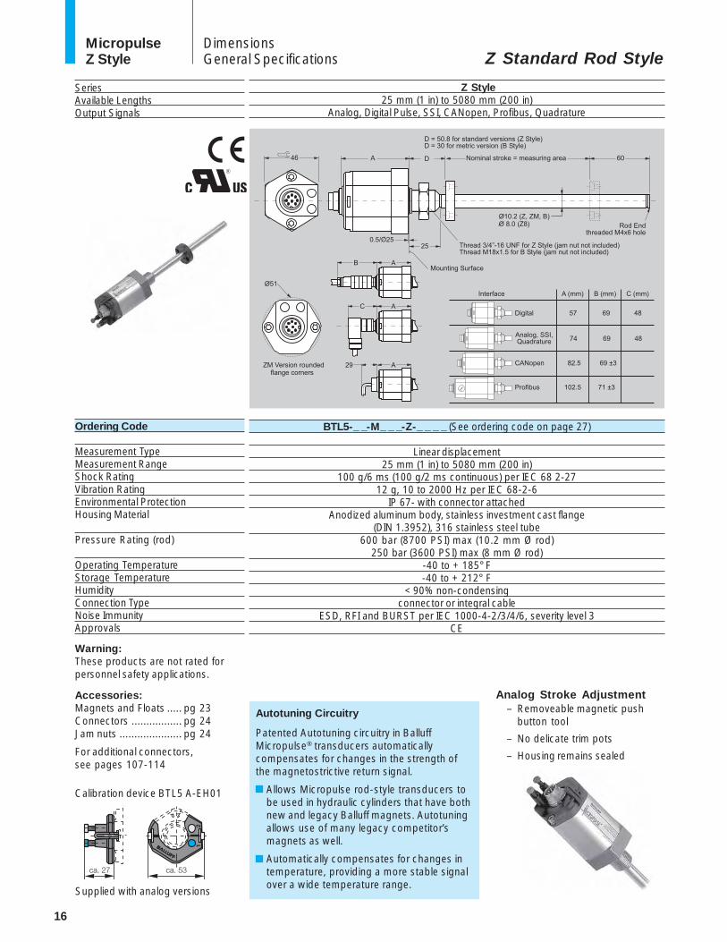
MicropulseZ Style Z Standard Rod Style
DimensionsGeneral Specifications
SeriesAvailable LengthsOutput Signals
Z Style25 mm (1 in) to 5080 mm (200 in)
Analog, Digital Pulse, SSI, CANopen, Profibus, Quadrature
Warning:These products are not rated forpersonnel safety applications.
Accessories:Magnets and Floats ..... pg 23Connectors ................. pg 24Jam nuts ..................... pg 24
For additional connectors,see pages 107-114
Ordering Code
Measurement TypeMeasurement RangeShock RatingVibration RatingEnvironmental ProtectionHousing Material
Pressure Rating (rod)
Operating TemperatureStorage TemperatureHumidityConnection TypeNoise ImmunityApprovals
Calibration device BTL5 A-EH01
Supplied with analog versions
Analog Stroke Adjustment– Removeable magnetic push
button tool
– No delicate trim pots
– Housing remains sealed
BTL5-_ _-M_ _ _-Z-_ _ _ _ (See ordering code on page 27)
Linear displacement25 mm (1 in) to 5080 mm (200 in)
100 g/6 ms (100 g/2 ms continuous) per IEC 68 2-2712 g, 10 to 2000 Hz per IEC 68-2-6
IP 67- with connector attachedAnodized aluminum body, stainless investment cast flange
(DIN 1.3952), 316 stainless steel tube600 bar (8700 PSI) max (10.2 mm Ø rod)
250 bar (3600 PSI) max (8 mm Ø rod)-40 to + 185° F-40 to + 212° F
< 90% non-condensingconnector or integral cable
ESD, RFI and BURST per IEC 1000-4-2/3/4/6, severity level 3CE
Autotuning Circuitry
Patented Autotuning circuitry in BalluffMicropulse® transducers automaticallycompensates for changes in the strength ofthe magnetostrictive return signal.
Allows Micropulse rod-style transducers tobe used in hydraulic cylinders that have bothnew and legacy Balluff magnets. Autotuningallows use of many legacy competitor’smagnets as well.
Automatically compensates for changes intemperature, providing a more stable signalover a wide temperature range.

17
MicropulseZ Style
BTLZ
www.balluff.com
DigitalStart/Stop PWM
P, M, N, I, L, R, K
Start/Stop or Pulse-width-modulated (RS422/RS485)
per specController dependent
±100 µm to 500 mm stroke,±0.02 % over 500 mm stroke
Resolution/ min 2 µm≤ 5 µm
500 Hz stroke > 2000 mm1 kHz stroke < 2000 mm (6 µm + 5 ppm*NL) / °C
24 Vdc ±20%, 10...30 Vdc or 15 Vdc ±2%
< 100 mA(at 1 kHz sampling rate)
Electrical Options
Electrical InterfaceElectrical TypePart No. Code (See pg. 27)
Output
Output LoadResolutionNon-linearity
RepeatabilityHysteresisSampling Rate
Temperature Coefficient*
Operating Voltage
Operating Current
AnalogCurrentE, C
4...20 mA, 0...20 mA
≤ 500 Ω≤ 0.66 µA
±100 µm to 500 mm stroke,±0.02 % over 500 mm stroke
Resolution/ min 2 µm≤ 5 µm 2 kHz
[0.6 µA/°C +(10 ppm/°C*P*V/NL)] * ΔT24 Vdc ±20%, 10...30 Vdc
or 15 Vdc ±2%< 150 mA
Nominal, @ 24 Vdc
Notes:Analog voltage outputversions incorporate bothrising and falling outputs.Analog current version mustbe ordered as rising or fallingouputs.
*Temperature coefficientvariables:VVVVV = output range in VIIIII = output range in [mA]ΔTTTTT = temperature changePPPPP = magnet positionNLNLNLNLNL = stroke length
AnalogVoltageA, B, G
0...+10 V, -5...+5 V, -10...+10 V
> 2K Ω (5 mA max)≤ 0.33 mV
±100 µm to 500 mm stroke,±0.02 % over 500 mm stroke
Resolution/ min 2 µm≤ 5 µm 2 kHz
[150 µV/° C +(5 ppm/°C*P*V/NL)] * ΔT
24 Vdc ±20%, 10...30 Vdc or 15 Vdc ±2%
< 150 mANominal, @ 24 Vdc
Analog and Digital Output Options for the Micropulse Z Style
RS-485 signal transmission with digital outputs
Two-Magnet Differential Mode– Available on Analog and PWM
– Output proportional to distance “S”
– Add “-D” suffix to ordering code

18
MicropulseZ Style Electrical Options Network Options
Ordering Code
Resolution
Non-linearityRepeatablity (resolution + hysteresis)HysteresisSampling RateTemperature CoefficientOperating VoltageOperating CurrentNetwork IsolationNetwork Speed
Network CompatibilityAddress SelectionCommunication TypesConfiguration SoftwareNumber of Magnets Supported
Notes:For more technical information,see pages 123-128
CANopenThis interface provides an efficient connectionto machines using CANopen. Featuresinclude:-Process data objects incorporatingposition, velocity and set-point information
-Emergency object for set-points-Service data objects for configuringtransducer modes
-Synchronization objects for network wideactivities
ProfibusThis interface provides an efficient connection tomachines using Profibus. Features of thisinterface include:-Single telegram message for fast updateseven with 4 magnets
-Operates at 12 Mbps-GSD file provided to configure telegrammessage
-Sync and Freeze functions available forcoordination between other devices
T
Position 5 µm (configurable)Velocity 0.1 mm/s increments (configurable)
±30 µm at 5 µm resolution±1 digit≤ 1 digit1 kHz
(6 µm + 5 ppm x L)/°C24 Vdc ±20%
≤ 120 mAyes
9.6, 19.2, 93.7, 187.5,900, 1500, 12000 kBaud
EN 50170 (Encoder Profile)DIP switch
Master/SlaveGSD file1, 2 or 4
H
Position 5 µm,Velocity 0.1 mm/s increments (selectable)
±30 µm at 5 µm resolution±1 digit≤ 1 digit1 kHz
(6 µm + 5 ppm x L)/°C24 Vdc ±20%
≤ 100 mAyes
10, 20, 50, 100, 125, 250,500, 800, 1000 kBaud
CiA Standard DS301, DS406 (Encoder Profile)Software/DIP switchProducer/Consumer
none required1, 2 or 4
BTL5-H1_ _-Mxxxx-Z-S94
Process Data1 = 1 x position & 1 x velocity2 = 2 x position & 2 x velocity3 = 4 x positionBaud Rate0 = 1 MBaud1 = 800 kBaud2 = 500 kBaud3 = 250 kBaud4 = 125 kBaud5 = 100 kBaud6 = 50 kBaud7 = 20 kBaud8 = 10 kBaudStroke Lengthxxxx = length in mm (see chart on page 27)Max = 156" (3962 mm)Connection Type1
S92 = one 5-pin (optional)S94 = two 5-pin M12 (standard)
Bus in: 5-pin male, M12Mating connector: BKS-S92-00 (female)
Bus out: 5-pin female, M12Mating connector: BKS-S94-00 (male)
DataFormat
No. of Magnets1 = 1 magnet2 = 2 magnets3 = 4 magnetsStroke Lengthxxxx = length in mmMax = 156" (3962 mm)(see chart on page 27)
Connection Type2
S103 = 3 connectors (standard):Power: 3-pin male, M8
Mating connector: BKS-S48-15-CP-xx (female)Bus in: 5-pin male, M12
Mating connector: BKS-S103-00 (female)Bus out: 5-pin female, M12
Mating connector: BKS-S105-00 (male)
BTL5-T1_0 -Mxxxx-Z-S103
1See pages 107-114 for mating cables/connectors.2See pages 107-114 for mating cables/connectors.
DataFormat

19
MicropulseZ Style
BTLZ
Specialized Interfaces Electrical Options
SSIThe SSI (synchronous serial interface) output interfaces with popular control systemsfrom manufacturers such as Allen-Bradley, Delta Computer, Siemens, Parker, Bosch-Rexroth and many others. Cable spans can be up to 400 m with noise-free operation.Individual, EEPROM linearization of this interface makes it ideal for applications requiringthe best accuracy available.
S
5, 10, 20 or 40 µm (see ordering code below)±30 µm or ±2 LSBs, whichever is greater
±1 digit≤ 1 digit2 kHz
(6 µm + 5 ppm x L)/°C100, 200, 400, 500, 1000 kHz
24 or 25 bits (binary or gray code)24 Vdc ±20% or 10...30 Vdc
≤ 80 mAStandard RS-485/422 levels
Ordering Code
ResolutionNon-linearity – Non-synchronizedRepeatablity (resolution + hysteresis)HysteresisSampling RateTemperature CoefficientCommunication SpeedsOutput ModesOperating VoltageOperating CurrentOutput
S _ _ _ B*
5, 10, 20 or 40 µm (see ordering code below)±30 µm or ±2 LSBs, whichever is greater
±1 digit≤ 1 digit2 kHz
(6 µm + 5 ppm xL)/°C100, 200, 400, 500, 1000 kHz
24 or 25 bits (binary or gray code)24 Vdc ±20% or 10...30 Vdc
≤ 80 mAStandard RS-485/422 levels
*S_ _ _ _B Versions
The internal interrogation of the S_ _ _ _B
version is synchronized to the externally
supplied clock pulses. This configuration
results in a more uniform, predictable data
update rate, and is better-suited for highly
dynamic closed-loop servo applications.
Like the standard version, the S_ _ _ _B
version is EEPROM linearized at the
factory.
BTL5-S_ _ _ _-Mxxxx-Z-_ _ _ _
Supply Voltage1 = +24 V5 = 10...30 VData Format0 = Binary, increasing, 24 bit1 = Gray code, increasing, 24 bit2 = Binary, falling, 24 bit3 = Gray code, falling, 24 bit6 = Binary, increasing, 25 bit7 = Gray code, increasing, 25 bit8 = Binary, falling, 25 bit9 = Gray code, falling, 25 bitSystem Resolution2 = 5 µm3 = 10 µm4 = 20 µm5 = 40 µm6 = 100 µm8 = 50 µmSynchronized DataB = synchronized*Blank = non-synchronizedStroke Lengthxxxx = length in mmMax = 156" (3962 mm)(see chart on page 27)Connection TypeS 32 = 8-pin connector (standard)1
S140 = MS connector (optional)2
KA02 = 2 m PUR cableKA05 = 5 m PUR cableKA10 = 10 m PUR cableKA15 = 15 m PUR cable
1See page 24 for mating cables/connectors.2See pages 107-114 for mating cables/connectors.
SSI Maximum cable lengthsCable length Clock Freq.
< 25 m < 1000 kHz< 50 m < 500 kHz
< 100 m < 400 kHz< 200 m < 200 kHz< 400 m < 100 kHz
Notes:

20
MicropulseZ Style
QuadratureThe quadrature output interfaces directly to standard encoder inputs (90° out ofphase, A & B). This configuration gives you more interface options for connectingto motion based systems. In addition, the Micropulse quadrature outputtransducer has the ability to provide absolute position information through useof its innovative BURST function.
Q
1, 2, 5 10, 50 µm, 0.001", 0.0001", 0.0005" (switch selectable)±100 µm to 500 mm stroke, ±0.02% over 500 mm strokeresolution + (±2 x resolution or 5 µm, whichever is greater)
±2 x resolution or 5 µm, whichever is greaterFree-running: 1 ms, 2 ms, 4 ms; Synchronous: 500 µs to 10 ms
(6 µm + 5 ppm x L)/°C10, 200, 400, 800 kHz
Free-running or Synchronous (switch selectable)24 Vdc ±20%, ±15 Vdc ±2%, 10...30 Vdc
≤ 80 mAStandard A & B (RS-422 level)
Ordering Code
ResolutionNon-linearityRepeatablity (resolution + hysteresis)HysteresisSampling RateTemperature CoefficientCommunication SpeedsOutput ModesOperating VoltageOperating CurrentOutput
BTL5-Q _ _ _ _-Mxxxx-Z-S140
Supply Voltage1 = +24 V2 = ±15 V5 = 10...30 VQuadrature Frequency0 = 833 kHz1 = 416 kHz2 = 208 kHz6 = 10 kHzSystem Resolution0 = 1 µm1 = 2 µm2 = 5 µm3 = 10 µm5 = 50 µm6 = 0.0001"7 = 0.001"8 = 0.0005"Mode/Update Rate0 = Synchronous (initiated by controller— consult factory)1 = free-running, 1 ms update — ≤ 1250 mm stroke only2 = free-running, 2 ms update — 1251 mm to 2500 mm4 = free-running, 4 ms update — ≥ 2501 mmStroke Lengthxxxx = length in mm(see chart on page 27)Connection TypeS140 = MS connector1
KA_ _ = Integral PVC cable (specify length in meters - 05 standard)
SSI Maximum cable lengthsCable length Clock Freq.
< 25 m < 1000 kHz< 50 m < 500 kHz
< 100 m < 400 kHz< 200 m < 200 kHz< 400 m < 100 kHz
Notes:
Electrical Options Specialized Interfaces
1See pages 107-114 for mating cables/connectors.
21
MicropulseZ Style
BTLZ
www.balluff.com
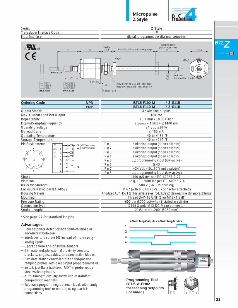
SeriesTransducer Interface CodeInput Interface
Ordering Code
Output SignalsMax. Current Load Per OutputRepeatabilityInternal Sampling FrequencyOperating VoltageNo-load CurrentOperating TemperatureStorage TemperaturePin Assignments
ShockVibrationDielectric StrengthEnclosure Rating per IEC 60529Housing MaterialMountingPressure RatingConnection TypeStroke Lengths
Z StyleF
digital, programmable discrete setpoints
BTL5 F100-M_ _ _ _*-Z-S115BTL5 F110-M_ _ _ _*-Z-S115
4 switching outputs100 mA
±0.1 mm / ±0.004 inchfSTANDARD = 1 kHz = ≤ 1400 mm
24 Vdc ±20 %≤ 100 mA
–40 to +185 °F–40 to +212 °F
switching output (open collector)switching output (open collector)switching output (open collector)switching output (open collector)
LA; programming input (low-active)GND
+24 Vdc (10...30 V not available)LB; programming input (low-active)100 g/6 ms per IEC 60068-2-27
12 g, 10...2000 Hz per IEC 60068-2-6500 V (GND to housing)
IP 67 (with IP 67 BKS-S... connector attached)Anodized Al/ 1.4571 (316) stainless steel rod, 1.3952 stainless investment cast flange
Thread 3/4"-16 UNF (Z) or M18×1.5 (B)600 bar (8700 psi) when installed in cylinder
S115 8-pole M12 DC Micro connector2" (51 mm)...200" (5080 mm)
Programming ToolBTL5-A-EH02for teaching setpoints(included)
Contact face
Rod Endthreaded M4x6 hole
Nominal stroke = measuring range
Damping zone(non-usable area)
Magnet
Thread 3/4"-16 UNF (Z) – standardThread M18x1.5 (B) – consult factory
BKS-S116 BKS-S116
4 Switching Outputs x 4 Switching Modes
NPNPNP
* See page 27 for standard lengths.
Pin 1Pin 2Pin 3Pin 4Pin 5Pin 6Pin 7Pin 8
50.8 (Z)30 (B)
Advantages– Four setpoints detect cylinder end-of-stroke or
anywhere in between– Interfaces to discrete I/O instead of more costly
analog inputs– Upgrade from end-of-stroke sensors– Eliminate multiple external proximity sensors,
brackets, targets, cables, and connection blocks– Eliminate motion controller: run speed/position
ramping profiles with direct-input proportional valve– Installs just like a traditional MDT in probe-ready
steel-walled cylinders– Auto-Tuning™ circuitry allows use of Balluff or
competitors’ magnets– Two easy programming options: local, with handy
programming tool; or remote, using teach-inconnections
BKS-S115

22
MicropulseZ Style
Rapid Replacement Module Option
Balluff’s new Rapid Replacement Module (RRM) option allows quickfield replacement without removing the pressure tube from thecylinder, making change-outs easy and cutting equipment downtime.
Advantages of the RRM include:– No hydraulic oil spillage and no need for environmental
containment– No danger from hot oil spilling onto repair personnel– No need to bleed air from hydraulic system after replacement– No danger of dirt entering open hydraulic port– 100% exchange of sensor package eliminates guesswork– Dimensionally identical to standard Balluff Z style for equivalent
output type– Backward-compatible with existing standard Balluff Z style
pressure tubes*– Available for all output types except Profibus, CANopen, and
ProSet4
The RRM can be installed in your maintenance program in a varietyof ways:
– For new installations, you can order optional ZM construction,which includes a Balluff pressure tube along with a RRM pre-installed. To change out this type, you simply remove twohousing screws, replace the RRM, re-tighten the two housingscrews – and you’re done.
– For new installations, you can also order standard Zconstruction, which includes a complete standard transducer.You can still do field swaps on this type by removing thestandard electronics head and internal waveguide element astwo separate components, then replacing both with a singleRRM unit.
– If you already have an installed base of standard Balluff Ztransducers, you can also change them out quickly with theRRM as described above. The RRM easily retrofits into existingBalluff pressure tubes once the old electronics and waveguideelement have been removed.*
– Keep spare RRM units on hand to maintain any Balluff ZM or Zconstruction transducer.
* Synchronized SSI RRM is not backward-compatible to standard pressuretubes used on non-synchronized SSI units. Synchronized SSI RRM onlyfits pressure tube supplied with complete synchronized SSI units.
BTL5-xxx-Mxxxx-ZM-xxx/RUOrdering Example – Rapid Replacemnet Module Only
Add "M" after "Z"
Add "/RU" at end of ordering code
Ordering Example – Complete Transducer Unit with RRM +Pressure Tube
BTL5-xxx-Mxxxx-ZM-xxx
Add "M" after "Z"
See page 27 for complete ordering code.

23
MicropulseZ Style
BTLZ
AccessoriesMagnets & Floats
ProductType
Magnet, SpacerØ32 open ring
Magnet, SpacerØ25 ring
MagnetØ22 ring
BTL-P-1013-4S*SPACER BTL-P-1013-DS
AL 12 gany
-40…+100°C
BTL-P-1012-4R*BTL Z-2-1012-4R-SPACER
AL 12 gany
-40…+100°C
Ordering Code - MagnetOrdering Code - Spacer
MaterialWeightMagnet SpeedOperating/StorageTemperature
BTL-P-1014-2RN/A
AL 10 gany
-40…+100°C
BTL2-S-3212-4Z
Stainless 31620 g
-40…+120°C
35 mm24 bar (348 psi)
Magnet, SpacerØ32 ring
BTL-P-1013-4R*BTL Z-P-1013-4R-SPACER
AL 12 gany
-40…+100°C
ProductType
MagnetBarrel float
MagnetBarrel float
MagnetBullet float
MagnetSphere float
Ordering Code
MaterialWeightOperating/StorageTemperatureWater DisplacementPressure (static)
BTL2-S-4414-4Z
Stainless 31635 g
-40…+120°C
30 mm20 bar (290 psi)
BTL2-S-6216-8P
Stainless 31666 g
-40…+120°C
41 mm15 bar (217 psi)
BTL2-S-5113-4K
Stainless 31634 g
-40…+120°C
26 mm40 bar (580 psi)
*Spacer is included with these magnets

24
MicropulseZ Style
Product
TypeStraight Connector
8-pin femaleRight-angle Connector
8-pin female
* Indicate cable length in ordering code in meters(consult factory for longer lengths)00 = connector only (only available for BKS-S 32M and BKS-S 33M)02 = 2 meter cable05 = 5 meter cable
For additional connectors,see pages 107-114
Ordering Code
MaterialContact SurfaceSolder ConnectionCableCable DiameterAllowable Cable DiameterCable MaterialEnvironmental Rating
BKS-S 32M-_ _
CuZn, nickel plated0.8 µm Au
00 option only7 x 0.25 mm2/AWG 246.35 mm ± 0.35 mm
6…8 mmPUR
IP 67 (when installed)
BKS-S 33M-_ _
CuZn, nickel plated0.8 µm Au
00 option only7 x 0.25 mm2/AWG 246.35 mm ± 0.35 mm
6…8 mmPUR
IP 67 (when installed)
Jam nut3/4"-16 UNF
BTL-5-JAM-NUT
Z housingStainless steel
ProductType
Ordering Code
ApplicationMaterial
Jam nutM18 x 1.5
BTL-A-FK01-E-M18x1.5
B/H housingStainless steel
AccessoriesConnectors
MoldedStraight Connector
8-pin female
BKS-S 232-PU-_ _
CuZn, nickel plated0.8 µm Au
N/A7 x 0.25 mm2/AWG 246.35 mm ± 0.35 mm
N/APUR
IP 67 (when installed)
MoldedRight-angle Connector
8-pin female
BKS-S 233-PU-_ _
CuZn, nickel plated0.8 µm Au
N/A7 x 0.25 mm2/AWG 246.35 mm ± 0.35 mm
N/APUR
IP 67 (when installed)
** * *
Note:Jam nut not needed forin-cylinder applications
25
MicropulseZ Style
BTLZ
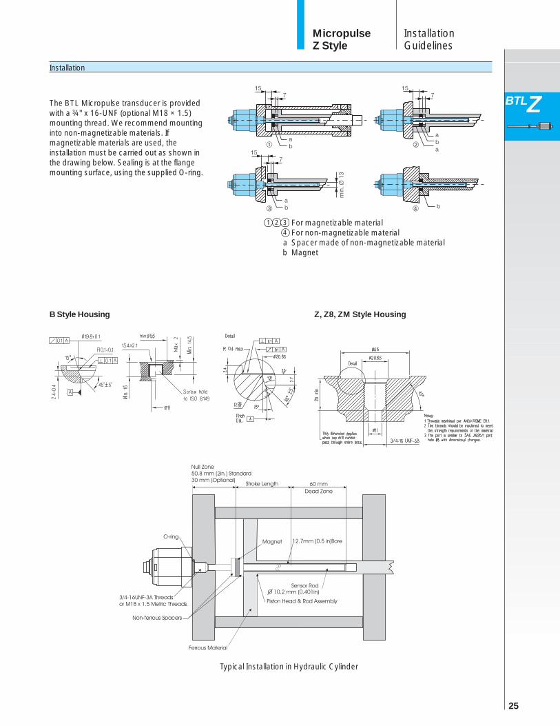
Installation
InstallationGuidelines
B Style Housing Z, Z8, ZM Style Housing
The BTL Micropulse transducer is providedwith a ¾" x 16-UNF (optional M18 × 1.5)mounting thread. We recommend mountinginto non-magnetizable materials. Ifmagnetizable materials are used, theinstallation must be carried out as shown inthe drawing below. Sealing is at the flangemounting surface, using the supplied O-ring.
Typical Installation in Hydraulic Cylinder
1 2 3 For magnetizable material4 For non-magnetizable materiala Spacer made of non-magnetizable materialb Magnet

26
MicropulseZ Style
Analog Wiring Diagrams
Digital Wiring Diagrams
SSI Wiring Diagram CANopen Wiring Diagram
Profibus Wiring Diagram Quadrature Wiring Diagram
IntegralCable
Wiring Diagrams
Note:
S32Connector
S32Connector
S32Connector
S103Connectors
S140Connector
S92Connector
S94Connector
IntegralCable
27
MicropulseZ Style
BTLZ
Ordering Code
B T L 5 - A 1 1 - M 0 3 0 5 - Z - S 3 2 - E 4 / U SK A 0 5
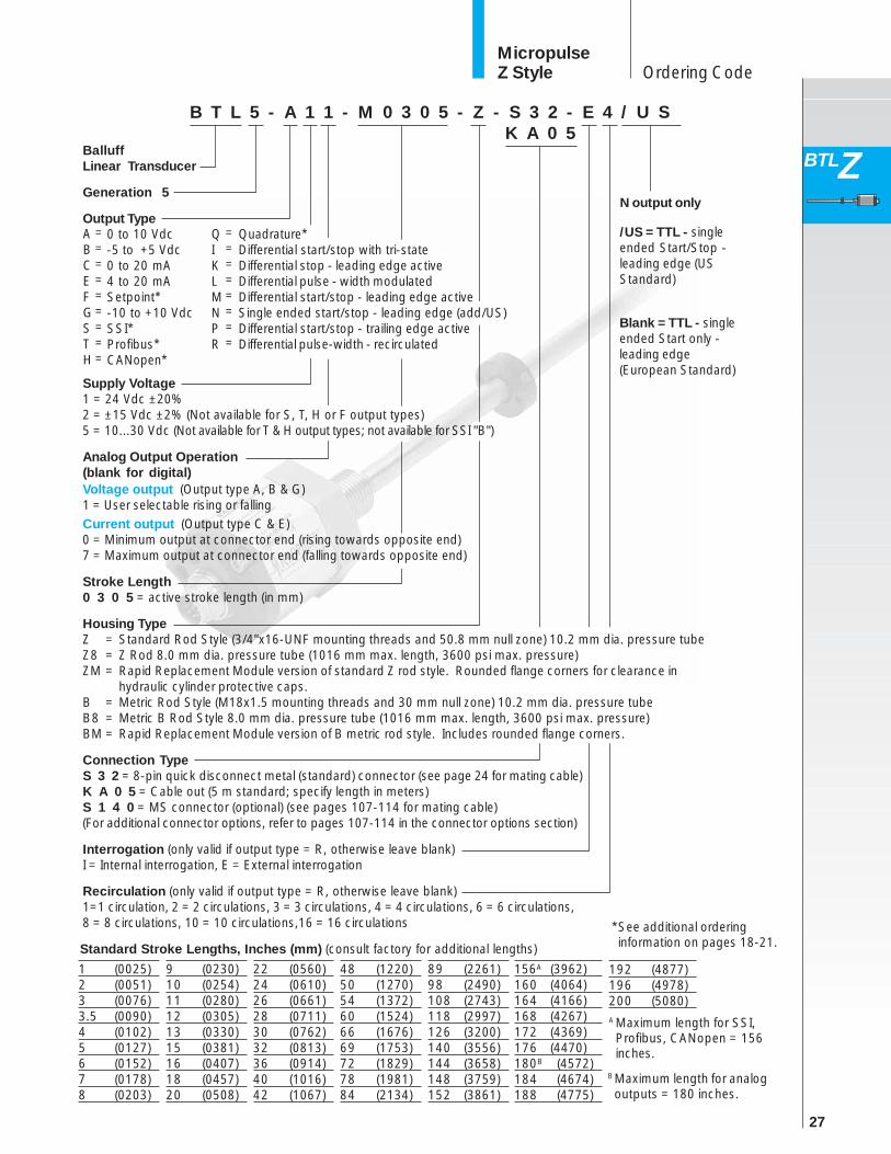
BMaximum length for analogoutputs = 180 inches.
Standard Stroke Lengths, Inches (mm) (consult factory for additional lengths)
/US = TTL - singleended Start/Stop -leading edge (USStandard)
N output only
Blank = TTL - singleended Start only -leading edge(European Standard)
A Maximum length for SSI,Profibus, CANopen = 156inches.
Quadrature*Differential start/stop with tri-stateDifferential stop - leading edge activeDifferential pulse - width modulatedDifferential start/stop - leading edge activeSingle ended start/stop - leading edge (add/US)Differential start/stop - trailing edge activeDifferential pulse-width - recirculated
QIKLMNPR
========
=========
ABCEFGSTH
* See additional orderinginformation on pages 18-21.
1 (0025)2 (0051)3 (0076)3.5 (0090)4 (0102)5 (0127)6 (0152)7 (0178)8 (0203)
9 (0230)10 (0254)11 (0280)12 (0305)13 (0330)15 (0381)16 (0407)18 (0457)20 (0508)
22 (0560)24 (0610)26 (0661)28 (0711)30 (0762)32 (0813)36 (0914)40 (1016)42 (1067)
48 (1220)50 (1270)54 (1372)60 (1524)66 (1676)69 (1753)72 (1829)78 (1981)84 (2134)
89 (2261)98 (2490)108 (2743)118 (2997)126 (3200)140 (3556)144 (3658)148 (3759)152 (3861)
156A (3962)160 (4064)164 (4166)168 (4267)172 (4369)176 (4470)180B (4572)184 (4674)188 (4775)
192 (4877)196 (4978)200 (5080)
BalluffLinear Transducer
Generation 5
Output Type
Supply Voltage1 = 24 Vdc ±20%2 = ±15 Vdc ±2% (Not available for S, T, H or F output types)5 = 10...30 Vdc (Not available for T & H output types; not available for SSI "B")
Analog Output Operation(blank for digital)Voltage output (Output type A, B & G)1 = User selectable rising or fallingCurrent output (Output type C & E)0 = Minimum output at connector end (rising towards opposite end)7 = Maximum output at connector end (falling towards opposite end)
Stroke Length0 3 0 5 = active stroke length (in mm)
Housing TypeZ = Standard Rod Style (3/4"x16-UNF mounting threads and 50.8 mm null zone) 10.2 mm dia. pressure tubeZ8 = Z Rod 8.0 mm dia. pressure tube (1016 mm max. length, 3600 psi max. pressure)ZM = Rapid Replacement Module version of standard Z rod style. Rounded flange corners for clearance in
hydraulic cylinder protective caps.B = Metric Rod Style (M18x1.5 mounting threads and 30 mm null zone) 10.2 mm dia. pressure tubeB8 = Metric B Rod Style 8.0 mm dia. pressure tube (1016 mm max. length, 3600 psi max. pressure)BM = Rapid Replacement Module version of B metric rod style. Includes rounded flange corners.
Connection TypeS 3 2 = 8-pin quick disconnect metal (standard) connector (see page 24 for mating cable)K A 0 5 = Cable out (5 m standard; specify length in meters)S 1 4 0 = MS connector (optional) (see pages 107-114 for mating cable)(For additional connector options, refer to pages 107-114 in the connector options section)
Interrogation (only valid if output type = R, otherwise leave blank)I = Internal interrogation, E = External interrogation
Recirculation (only valid if output type = R, otherwise leave blank)1=1 circulation, 2 = 2 circulations, 3 = 3 circulations, 4 = 4 circulations, 6 = 6 circulations,8 = 8 circulations, 10 = 10 circulations,16 = 16 circulations
0 to 10 Vdc-5 to +5 Vdc0 to 20 mA4 to 20 mASetpoint*-10 to +10 VdcSSI*Profibus*CANopen*

For sales and technical information, Contact us at:
6194 Notre Dame WestMontreal, Quebec H4C 1V4TOLL-FREE: 855-341-3415
211 Watline Ave, Unit 205Mississauga, Ontario L4Z 1P3
TEL: 905-829-2910TOLL-FREE: 855-341-3415
E-MAIL: [email protected]
www.cowandynamics.com