Embed Size (px)
Citation preview
Z-SPIKE REJUVENATION TO SALVAGE TIMBER RAILROAD BRIDGE MEMBERS
Nathan J. Miller Richard M. Gutkowski, Ph.D., PE
Jeno Balogh, Ph.D. Dept. of Civil and Environmental Engineering
Colorado State University Ft. Collins, Colorado
Don W. Radford, Ph.D.
Dept. of Mechanical Engineering Colorado State University
Ft. Collins, Colorado
December 2008

Acknowledgements This report has been prepared with funds provided by the United States Department of Transportation to the Mountain Plains Consortium. The researchers express their gratitude to the Association of American Railroads, Dr. Duane Otter, principal engineer at its Transportation Technology Center, Inc., and Mr. Steve Millsap, AVP Structures, and BNSF Railway for their assistance in soliciting salvaged timber railroad stringers needed for the project. The BNSF Railway provided material from several rail yards in Colorado. It also provided for delivery of used members made available by Mr. Tomasz Gawronski, manager bridge maintenance at Union Pacific Railway, from an actual bridge in Texas. Mr. Elwood Starner, supervisor structures – BNSF Railway in Denver, Colorado, provided the crew assistance needed for ground delivery to the CSU campus from the rail yards and from the rail car drop point for the shipment obtained from Texas. The Union Pacific Railroad and Great Western Railroad cooperated in moving the beams from Texas to Fort Collins via their rail lines. The researchers also thank Chris Turnbull-Grimes for being willing and able to assist with this project when needed. French interns Jonathan Pernot, Jonathan Guiet, Jean-Baptiste Dumas, and Jonathan Finot also provided valuable assistance in the laboratory. Erin Dallinger provided clerical support in preparing this report. Disclaimer The contents of this report reflect the views of the authors, who are responsible for the facts and the accuracy of the information presented. This document is disseminated under the sponsorship of the Departments of Transportation, University Transportation Centers Program, in the interest of information exchange. The U.S. government assumes no liability for the contents or use thereof.
North Dakota State University does not discriminate on the basis of race, color, national origin, religion, sex, disability, age, Vietnam Era Veterans status, sexual orientation, marital status, or public assistance status. Direct inquiries to the Chief Diversity Officer, 205 Old Main, (701) 231-7708.

ABSTRACT This research study examined the effectiveness of the fiber reinforced polymer (FRP) spikes in repairing naturally damaged and deteriorated railroad bridge chords. Past research has shown that this process can be quite effective in improving the effective stiffness of railroad chord members that were intentionally damaged. This shear spiking process involves inserting the FRP spikes vertically into railroad bridge members. The spikes are held in place by an adhesive and are intended to repair horizontal cracks that develop in the members over the course of their lifespan. This study included three specimens that were of varying size and damage conditions. In each case, the spiking technique as well as the overall improvement in specimen stiffness was analyzed. This report summarizes the spiking process used in each specimen as well as the results. It was found that the increase in the stiffness of the specimens was highly dependent on the initial condition of the specimens. The last specimen in the study showed the most promising results as it was also the most damaged. The spikes were installed in slightly oversized holes with epoxy resin as the adhesive. This specimen experienced a 267% increase in the initial effective stiffness when loaded to 15 kips. After a test to 39 kips, this increase was reduced to 179%. This result confirms the potential for shear spiking as a highly effective tool for in situ repair of damaged or deteriorated railroad bridge beams.


TABLE OF CONTENTS
1. INTRODUCTION ................................................................................................................... 1
2. BACKGROUND ...................................................................................................................... 3
3. MATERIALS ........................................................................................................................... 7
3.2 Spikes .................................................................................................................................. 7 3.3 Adhesive .............................................................................................................................. 8
4. TEST PROCEDURE ............................................................................................................... 9
5. TEST RESULTS .................................................................................................................... 11
5.1 Specimen 1 ........................................................................................................................ 11 5.2 Specimen 2 ........................................................................................................................ 14
5.2.1 Specimen Drying ..................................................................................................... 19 5.3 Specimen 3 ........................................................................................................................ 21
6. RECOMMENDATIONS AND CONCLUSIONS ............................................................... 29
7. REFERENCES ....................................................................................................................... 31

LIST OF TABLES Table 3.1 Test Specimen Summary .................................................................................................. 7 Table 5.1 Test Data for Specimen 1 ............................................................................................... 12 Table 5.2 Test Data for Specimen 2 ............................................................................................... 16

LIST OF FIGURES Figure 3.1 Deterioration and damage for Specimen 3 (left: Splits on the end;
right: longitudinal cracks) ......................................................................................... 7 Figure 3.2 Spikes prepared for installation ................................................................................ 8 Figure 4.1 Test set-up ................................................................................................................ 9 Figure 4.2 Example of load and deflection data from load test of Specimen 3 ....................... 10 Figure 5.1 Specimen 1 spiking layout ...................................................................................... 11 Figure 5.2 Percent gain in effective stiffness versus rows of spikes added – Specimen 1 ....... 12 Figure 5.3 Load versus deflection plotted to failure – Specimen 1.......................................... 13 Figure 5.4 Crushing at west end support of Specimen 1 .......................................................... 13 Figure 5.5 Spikes from Specimen 1 after failure (polyester resin) .......................................... 14 Figure 5.6 Spike layout for Specimen 2 ................................................................................... 15 Figure 5.7 (left) Horizontal cracks visible on one end of Specimen 2. (right) No visible
damage on the sides of the specimen. ..................................................................... 16 Figure 5.8 Percent gain in effective stiffness versus number of rows of spikes added
to Specimen 2 ......................................................................................................... 17 Figure 5.9 Spikes from Specimen 2. (polyester resin: left; epoxy resin: right) ....................... 18 Figure 5.10 (left) Polyester-cracks visible between spike and wood.
(right) Epoxy-no visible cracks. ............................................................................. 18 Figure 5.11 Polyester resin drying specimen (left: before drying; right: after drying) .............. 19 Figure 5.12 End view of dried polyester resin specimen ........................................................... 20 Figure 5.13 Epoxy resin drying specimen (left: before drying; right: after drying) .................. 20 Figure 5.14 End view of epoxy specimen after drying .............................................................. 21 Figure 5.15 Splits and checking visible on side of Specimen 3 ................................................. 22 Figure 5.16 Damage to one end of Specimen 3 ......................................................................... 22 Figure 5.17 Specimen 3 spike layout ......................................................................................... 23 Figure 5.18 Percent increase in EI for Specimen 3 .................................................................... 24 Figure 5.19 Specimen 3 loaded to 30 kips. ................................................................................ 25 Figure 5.20 Specimen 3 loaded to 39 kips ................................................................................. 26 Figure 5.21 Specimen 3 loaded to 10 kips after high load tests. ................................................ 26 Figure 5.23 Percent increase in EI for Specimen 3 including test 10. ....................................... 28


EXECUTIVE SUMMARY It is critical to maintain the safety and economic vitality of the nation’s railroad infrastructure. These vital links for the movement of agricultural commodities and other freight often depend on aging bridges. The research described herein will assist bridge owners by providing a fundamentally new, more structurally effective, substantially lower cost alternative to presently limited repair methods based on fiber composites. Common approaches to using fiber reinforced composites for in situ bridge repair are fiberglass wrap (bandages) or adding reinforcing plates (patches) to the sides of members. These techniques require that the members be removed from the bridge for repair to be made and degrade with time due to weather exposure. “Shear Spiking” (adapted from “Z-spiking,” a method of construction used in the aerospace industry) is an alternative to the above techniques for application to timber bridge members. Shear spikes are composite rods inserted into pre-drilled holes with an adhesive bonding them to the wood. They restore overall stiffness and add horizontal shear resistance but do not require member removal and are not exposed to weather. Researchers at Colorado Sate University (CSU) have been very active in pursuing this adaptation in the setting of rehabilitation of timber railroad bridge members (see MPC Reports No. 00-112, by D. Radford et al, No.04-163 by TJ Schilling et al, No. 05-173 by T. Burgers et al., and No.07-190 by Gutkowski and Forsling). As part of that past work, new timber bridge stringers with different types of intentional severe inflicted damage were load tested under initial ramp, repeated loading and failure loading with indications of a high degree of success. Subsequently, The Union Pacific railroad provided some deteriorated, damaged members (some from rail yards, some removed from actual field bridges) for laboratory tests after implementation of shear spiking. That work is the basis of this report. Several of the salvaged stringers were incrementally reinforced with shear spikes and load tested either after each increment of spiking or after all spikes were installed. The effect on stiffness was observed, and once benefits tapered off for added shear spikes, a load test to destruction was conducted to determine ultimate load capacity. There was a minor gain in specimens with little existing damage. When loaded to 15 kips, up to a 267% increase in effective stiffness was seen for stringers in very poor condition. After loading one stringer to 39 kips, the increase in stiffness relative to the initial dropped to 179%. The tests showed varying degrees of improvement, but overall it was shown that heavily damaged stringers can experience significant increases in effective stiffness. At ultimate load, the repaired stringers failed in a progressive pseudo-ductile manner instead of the brittle flexural failure mode commonly experienced in timber beams. This is attributed to the enhanced interlayer shear capacity provided by the shear spikes. This suggests that while not increasing the stiffness of new stringers, reinforcing with shear spikes might prevent brittle failure and sudden collapse. Tests performed with an epoxy resin vs. an alternative polyester resin showed that the epoxy formed a more definite bond with the wood with increased strength. This increase in bond strength tends to offset the higher cost of the epoxy as compared to the polyester resin. Lightly sanding the spikes before their insertion improves bonding between the adhesive and the spike. A slightly oversized hole allows for a thicker layer of epoxy as well as making it easier to insert the spikes. Using milled fiberglass as filler thickens the epoxy so that it can better fill voids in heavily damaged stringers.

In many installations, timber railroad bridges are 50+ years old but still necessary for daily operation. It is increasingly difficult to obtain large size timber members needed for repair and upgrading such bridges. Hence, economic repair of bridges is vital as an alternative to replacement of members. As the shear spikes are made from commercially available rods, easily installed and imbedded in the member, they are invaluable as a low-cost, long-lasting, repair. This research described herein shows promise of leading to invaluable, affordable technology for repairing aged timber railroad bridges. The technology is equally promising for timber stringer bridges on secondary roads.

1
1. INTRODUCTION The purpose of this research study was to continue work done by researchers at Colorado State University (CSU) in previous projects focused on the development and application of a technique termed Z-spiking (loosely referred to as “shear spiking”) for stiffening timber railroad bridge members. Several prior projects have been done which have experimentally examined the effectiveness of shear spiking as a method for repairing damaged or deteriorated railroad crossties and bridge beams. The results indicated that the method can be highly effective depending on the extent of deterioration or damage present in the members. Testing has been done with full-sized members; however, in the case of bridge beams, the original members available were not of sufficient existing damage to determine the effectiveness of the repair method. Consequently, damage was inflicted upon the members by cutting them longitudinally with a chainsaw to simulate some simple damage conditions. Shear spiking proved to be a successful method for repairing these members. This research study involved repeating some of the previous load testing to confirm the shear spiking method as an effective method for repairing naturally damaged railroad bridge chords. A number of used railroad chords had been made available from rail yards and bridge sites in Colorado and Texas. The chords were of different spans as well as different degrees of damage and deterioration. The load testing was used as a means to assess the effectiveness in improving the stiffness of railroad chords composed of stringers of varying size and quality. In addition, past tests suggested an alternative adhesive might be better suited for this application than the epoxy resin used in past tests. The type of adhesive as well as the adhesive application process was examined with these salvaged chords.

2

3
2. BACKGROUND As stated above, a number of research projects have been done to study the effectiveness and practicality of the Z-spiking technique. Z-spiking is a procedure in which fiberglass reinforced polymer (FRP) rods are inserted vertically (perpendicular to the bending axis) to connect layers of a laminated member and carry interlayer shear in such members. In the case of deteriorated railroad chords, the shear spikes reconnect the regions of the members separated by cracks and recover some of the stiffness of the beams that was lost due to the cracks. Past projects have examined the effectiveness of this process by using dimension lumber, naturally deteriorated railroad cross ties, and artificially damaged full-sized railroad chords. The following is a summary of the testing procedures for each of these members and the results that were observed. Radford et al.1-4
The first research conducted at CSU investigating the effectiveness of shear spiking was done using dimension lumber. In one case, two nominal 2x2 dimension lumber members were interconnected with shear spikes to determine the increase in stiffness over two 2x2’s that were not connected at all. The other test that was done involved nominal 2x4 members. Individual members were first tested in their undamaged state. Each was then cut longitudinally at mid-depth from one end to within 2 inches of midspan of the member in order to simulate severe damage. Shear spikes were added incrementally to observe the increase in stiffness due to the shear spikes. The repair of the test specimens indicated that much of the stiffness lost due to the damage could be recovered via the shear spiking process. It was recommended that testing of the shear spiking procedure be continued on larger timber members. Schilling et al.5-8 Schilling applied the concept of shear spiking to naturally damaged and deteriorated railroad crossties. This was intended as an intermediate step between the work on dimension lumber and the goal of full-sized railroad stringers. The specimens used varied in quality. Two classification systems were created by the researchers and used for sorting the crossties into groups. One criterion was a visual inspection in which the crossties were sorted based on size, number, and location of cracks. The other criterion was based on the stiffness of the crosstie as measured in a preliminary load test. In each of these tests, the specimens were given either a low, medium, or high ranking. Putting them together, possible rankings were low, medium-low, medium, medium-high, and high. Ten crossties from the low quality group and 10 crossties from the medium-high quality group were tested. The beams were spiked incrementally at a spacing of 7.2 inches with load tests performed after each row of two spikes on each end of the crosstie was inserted. After all load tests had been performed, the average gain in flexural stiffness was determined from measured deflections. The group of medium-high quality crossties had an average increase of 41.0% while the low quality group had an average increase of 64.8%. Overall, the finding of this project was that the shear spiking technique was effective in increasing the stiffness of the crossties in question. It was recommended that the spacing of the spikes be studied as well as the effect of their placement. It was also thought that mix ratios of the epoxy used could have an influence of the overall strength of the bond between the spikes and wood as well as impacting the cure time. Burgers et al.9-12
Burgers performed the first tests of the shear spiking technique on full-scale railroad chord members. These tests were done on intentionally damaged members arranged in a three-span, four-stringer bridge

4
chord. Initially, the researchers attempted to create the damage with two types of manual saws. However, due to the size and condition of the stringers, this was futile. Instead, a chainsaw was used to damage the chord by making a horizontal cut at mid-depth of the stringers across the width of the chord. This damage was inflicted on both ends of the center span resulting in an extreme damage condition. The damage that resulted was a much wider crack than the researchers had intended so the crack was shimmed before any of the shear spikes were installed in the specimen. Before any of the intentional damage was done, an initial load test was performed to find the effective stiffness in the undamaged state. The effective stiffness was defined as EI, the product of the modulus of elasticity and the moment of inertia. After the chord had been damaged, a fully damaged effective stiffness was determined from a load test. Using those two effective stiffnesses, a percent recovery could be found as rows of spikes were added to the damaged areas of the chord members. Overall, an average percent recovery of 91.6% was observed after all rows of spikes were installed. This improved upon the findings of Radford, et al. and Schilling, et al. and confirmed the possibility of shear spiking being an effective technique for repairing damaged chords in situ. Forsling et al.13-15 Forsling continued the research of the shear spiking technique by investigating the effect that cyclic loading had on the shear spike repair. Eight full-sized individual chord members were tested. All of the members were approximately 175 inches long with a cross section of 8- by 16-inches, and the clear span for the load tests was 159 inches. Since their condition was very good to new, the members needed to be intentionally damaged before they could be repaired. The damage was done by cutting one-third of the span on each end of the specimen with a chainsaw which again resulted in a very severe damage condition. Four different damage cases were studied which resulted in two specimens with each damage case. The first case was a horizontal cut across the entire width of the specimen at the neutral axis location. This damage case was referred to as one full cut, 1F. The second case was a cut at the neutral axis location that left the middle two inches of the specimen uncut. This damage state was referred to as one partial cut, 1P. The last two damage scenarios added an additional cut half way between the neutral axis and the bottom of the specimen. These specimens had either two full cuts, 2F, or two partial cuts, 2P. As one might expect, the chord members that were damaged more significantly had more to gain from the repair process and saw greater gains in the effective stiffness as a result of the shear spiking repair. The specimens that had partial cuts (1P and 2P) initially lost an average of 12% of the initial effective stiffness after the damage had been caused. Upon being fully spiked, the average effective stiffness was 96% of the initial value. This was a gain of 8% relative to the initial stiffness but a regain of 67% of what had been lost. The specimens that had full cuts (1F and 2F) lost an average of 34% of their initial effective stiffness when the damage was inflicted. Upon full repair, the average effective stiffness was 77% of the initial value. This corresponds to a gain of 41% of the initial value or a regain of 64% of what had been lost. This indicated that while the increases in stiffness were small for the specimens with partial cuts, the gains in effective stiffness based on the stiffness lost due to the damage was still significant. It should be noted that the results from the partial cut specimens showed very small changes on three of the specimens and a larger gain on the fourth specimen. Clearly, the shear spiking process has the potential for improving the effective stiffness of railroad stringers of varying damage conditions, but more heavily damaged stringers will likely benefit more from the repair process. Once the beams had been fully repaired, they were subjected to durability loading. Four of the stringers (one of each damage condition) were loaded to a deflection of L/500 for 25,000 cycles. Three of these specimens saw negligible changes in effective stiffness over the 25,000 cycles. The fourth specimen (2F) saw a slightly larger decrease in effective stiffness as it dropped to 88.2% of its effective stiffness at the beginning of the cyclic loading. The other four stringers were loaded to a deflection of L/300 for 10,000 cycles. Only one of the stringers (1P) experienced negligible changes in effective stiffness under this loading. The effective stiffness of the other three stringers dropped to 79.6% (1F), 66.7% (2F), and 46.7%
5
(2P) of effective stiffness at the beginning of the cyclic loading. Each of these stringers showed evidence of partial failures early on in their loading cycles in the form of the propagation of shear cracks as well as significant interlayer slip. Since these failures occurred early in the loading cycle (before 2,500 cycles had been reached), it was believed they were the result of overloading the stringers themselves rather than any sort of fatigue effects in the shear spiking repair. If the beams were overloaded, this may have resulted in the propagation of the cracks into the middle (initially undamaged) portion of the specimens or through the middle of the partial cuts in specimens 1P and 2P. After cyclic loading, three of the L/300 specimens which had experienced partial failures in the durability loading were dissected so the bond between the spikes and the wood of the stringers could be observed. Some debonding of the epoxy adhesive was noted which may have contributed to the failure. A possible explanation offered by the researchers was that the method used for inflicting the intentional damage may have caused this debonding. The intentional damage had been done with saws that had significant thickness. This left gaps in the specimens tested. As the specimens were loaded, these cracks could try to open and close, possibly generating large vertical shear forces on the bond of the repair. Even though the debonding did occur, the shear spikes maintained much of their shear resistance. Lastly, the five stringers that had not been damaged in the cyclic loading were ramp loaded to failure. The ultimate failure mode observed was flexural failure of the tensile wood fibers. The strength of the wood fibers governed the failure rather than the strength of the shear spike repair. In some cases, noncatastrophic shear failures did occur before the ultimate flexural failure. Even with these shear failures, the specimens maintained much of their load resistance. This suggested that the shear spikes had sufficient strength to be used in the repair of the damaged railroad beams. The findings of Forsling’s research were sufficient to move forward with further study of naturally deteriorated railroad beams. The debonding observed suggested an examination of the adhesive as well.

6

7
3. MATERIALS 3.1 Specimens The specimens involved in this study included three naturally deteriorated railroad specimens. The specimen dimensions are summarized in Table 3.1. Table 3.1 Test Specimen Summary
Number of Stringers
Stringer Cross‐Section
Total Length
Test Clear Span
Source
Specimen 1 1 15" x 7" 132' 104.81" Colorado
Specimen 2 3 15" x 7" 126" 104.81" Colorado
Specimen 3 4 17" x 7.5" 175" 150.75" Texas
These specimens had varying degrees of deterioration and damage. Specimens 1 and 2 had very little damage. There were some visible cracks on the sides and ends of the specimens. None of these cracks could be considered very significant, and it was anticipated that there would be relatively small increases in the stiffness of these specimens due to the shear spiking process. Specimen 3 had much more significant damage. There were large splits on the sides and ends of the specimen. The damage to Specimen 3 is shown in Figure 3.1. Because of the large degree of damage to this specimen, it was anticipated that it would experience the largest increase in stiffness due to the spiking process.
Figure 3.1 Deterioration and damage for Specimen 3 (left: splits on the end; right: longitudinal cracks)
3.2 Spikes The spiking material used was a fiber reinforced polymer rod. The rod used was a ¾ in. diameter Polyglass Polyester rod manufactured by Liberty Pultrusions.16 This rod was used to remain consistent with previous research projects that have been done involving the Z-spiking process. The rod is reinforced with unidirectional glass fiber, along the length of the pultrusion. Some of the advantages of the spiking material include corrosion resistance and a high strength-to-weight ratio. The rods were purchased in 10-ft. lengths which were cut into “spikes” of a length 1 inch less than the depth of the stringer being tested. This allowed for the spike to be installed in the specimens with 1 inch of clear wood left below it. The
8
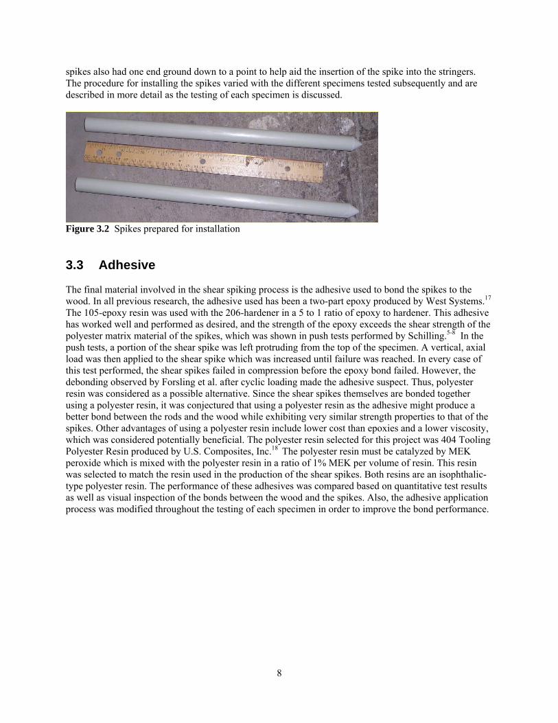
spikes also had one end ground down to a point to help aid the insertion of the spike into the stringers. The procedure for installing the spikes varied with the different specimens tested subsequently and are described in more detail as the testing of each specimen is discussed.
Figure 3.2 Spikes prepared for installation 3.3 Adhesive The final material involved in the shear spiking process is the adhesive used to bond the spikes to the wood. In all previous research, the adhesive used has been a two-part epoxy produced by West Systems.17 The 105-epoxy resin was used with the 206-hardener in a 5 to 1 ratio of epoxy to hardener. This adhesive has worked well and performed as desired, and the strength of the epoxy exceeds the shear strength of the polyester matrix material of the spikes, which was shown in push tests performed by Schilling.5-8 In the push tests, a portion of the shear spike was left protruding from the top of the specimen. A vertical, axial load was then applied to the shear spike which was increased until failure was reached. In every case of this test performed, the shear spikes failed in compression before the epoxy bond failed. However, the debonding observed by Forsling et al. after cyclic loading made the adhesive suspect. Thus, polyester resin was considered as a possible alternative. Since the shear spikes themselves are bonded together using a polyester resin, it was conjectured that using a polyester resin as the adhesive might produce a better bond between the rods and the wood while exhibiting very similar strength properties to that of the spikes. Other advantages of using a polyester resin include lower cost than epoxies and a lower viscosity, which was considered potentially beneficial. The polyester resin selected for this project was 404 Tooling Polyester Resin produced by U.S. Composites, Inc.18 The polyester resin must be catalyzed by MEK peroxide which is mixed with the polyester resin in a ratio of 1% MEK per volume of resin. This resin was selected to match the resin used in the production of the shear spikes. Both resins are an isophthalic-type polyester resin. The performance of these adhesives was compared based on quantitative test results as well as visual inspection of the bonds between the wood and the spikes. Also, the adhesive application process was modified throughout the testing of each specimen in order to improve the bond performance.
9
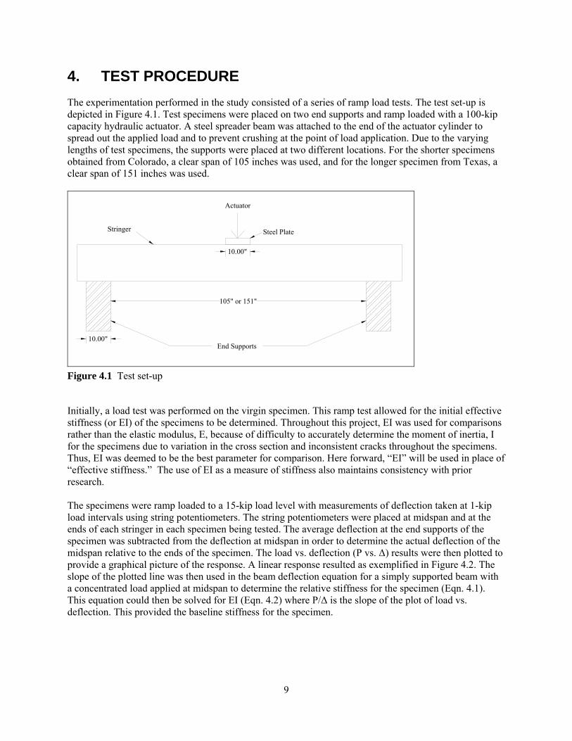
4. TEST PROCEDURE The experimentation performed in the study consisted of a series of ramp load tests. The test set-up is depicted in Figure 4.1. Test specimens were placed on two end supports and ramp loaded with a 100-kip capacity hydraulic actuator. A steel spreader beam was attached to the end of the actuator cylinder to spread out the applied load and to prevent crushing at the point of load application. Due to the varying lengths of test specimens, the supports were placed at two different locations. For the shorter specimens obtained from Colorado, a clear span of 105 inches was used, and for the longer specimen from Texas, a clear span of 151 inches was used.
10.00"
105" or 151"
10.00"
Actuator
Stringer
End Supports
Steel Plate
Figure 4.1 Test set-up
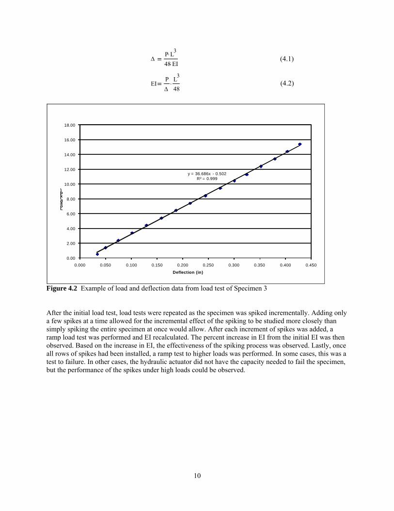
Initially, a load test was performed on the virgin specimen. This ramp test allowed for the initial effective stiffness (or EI) of the specimens to be determined. Throughout this project, EI was used for comparisons rather than the elastic modulus, E, because of difficulty to accurately determine the moment of inertia, I for the specimens due to variation in the cross section and inconsistent cracks throughout the specimens. Thus, EI was deemed to be the best parameter for comparison. Here forward, “EI” will be used in place of “effective stiffness.” The use of EI as a measure of stiffness also maintains consistency with prior research. The specimens were ramp loaded to a 15-kip load level with measurements of deflection taken at 1-kip load intervals using string potentiometers. The string potentiometers were placed at midspan and at the ends of each stringer in each specimen being tested. The average deflection at the end supports of the specimen was subtracted from the deflection at midspan in order to determine the actual deflection of the midspan relative to the ends of the specimen. The load vs. deflection (P vs. Δ) results were then plotted to provide a graphical picture of the response. A linear response resulted as exemplified in Figure 4.2. The slope of the plotted line was then used in the beam deflection equation for a simply supported beam with a concentrated load applied at midspan to determine the relative stiffness for the specimen (Eqn. 4.1). This equation could then be solved for EI (Eqn. 4.2) where P/Δ is the slope of the plot of load vs. deflection. This provided the baseline stiffness for the specimen.
10
. (4.1)
. . (4.2)
y = 36.686x - 0.502R² = 0.999
0.00
2.00
4.00
6.00
8.00
10.00
12.00
14.00
16.00
18.00
0.000 0.050 0.100 0.150 0.200 0.250 0.300 0.350 0.400 0.450
Load (kip)
Deflection (in)
Figure 4.2 Example of load and deflection data from load test of Specimen 3 After the initial load test, load tests were repeated as the specimen was spiked incrementally. Adding only a few spikes at a time allowed for the incremental effect of the spiking to be studied more closely than simply spiking the entire specimen at once would allow. After each increment of spikes was added, a ramp load test was performed and EI recalculated. The percent increase in EI from the initial EI was then observed. Based on the increase in EI, the effectiveness of the spiking process was observed. Lastly, once all rows of spikes had been installed, a ramp test to higher loads was performed. In some cases, this was a test to failure. In other cases, the hydraulic actuator did not have the capacity needed to fail the specimen, but the performance of the spikes under high loads could be observed.
ΔP L3⋅
48 EI⋅
EIPΔ
L3
48⋅

11
5. TEST RESULTS 5.1 Specimen 1 Specimen 1 was a single 11-ft. long member with a 7- by 15-inch cross section which was slightly damaged. The most evident damage to the specimen was a horizontal crack running nearly the entire length of the specimen at about mid-depth which was visible on one side of the specimen. There was no severe damage to the stringer so it was believed that spiking would have a small impact on the EI of the stringer. For this stringer, the polyester resin was used to observe its effectiveness as an adhesive. The spiking procedure for this specimen involved first drilling the holes for the spikes. The holes were first predrilled to a diameter of ½ in. Then the holes were drilled to the diameter of the spike, ¾ in. Two fl. oz. of the polyester resin were then poured into the hole, and the spike was inserted. The hole for the spike had no clearance, so a dead blow hammer (sand-filled plastic hammer) was used to drive the spike into place. In some cases, the dead blow hammer could not apply sufficient force so it was necessary to use a conventional hammer to install the spike. In general, a conventional hammer should not be used because it has a tendency to damage the end of the spike. The testing of this specimen consisted of a series of load tests to the 15-kip load level followed by a single test to failure. The individual load tests were performed after each row of spikes was installed. The layout of the spikes is shown in Figure 5.1. The first five rows of spikes were installed using a 10.5 inch spacing to remain consistent with previous research. However, once those rows had been installed, the specimen still displayed an increasing EI, but there was no additional space to add spikes closer to midspan by the prescribed method. Because of this, the sixth row was added to the end of the specimen, 5 inches outside of the first row that was inserted. This is consistent with past research (Radford et al. ) which showed such exterior spikes are effective.
Row 5Row 4Row 3Row 2Row 1Row 6
15.00"
132.00"
105
7.50" 2.50"
5.00" 10.50"
Figure 5.1 Specimen 1 spiking layout

12
The results for Specimen 1 are listed in Table 5.1 and illustrated in Figure 5.2. The outcome was that the spiking process was modestly effective in increasing the EI of the specimen. The first five rows of spikes each showed constant gains in the EI of the specimen. These gains were approximately 5% with each row of spikes added, resulting in a total increase in the EI of 24.42%. After the first five rows of spikes had been added, there was still a notable gain in the EI from the previous test. Because of this, the sixth row of spikes was added. With the addition of the sixth row of spikes, it was clear that the increases in stiffness were diminishing though the overall EI was still increasing. However, since the increase in EI was minimal and there were no practical locations to add more spikes at the same spacing, no more were added. Table 5.1 Test Data for Specimen 1
Test Spiking EI (kip-ft^2) % Gain0 Test 1 No Spikes 7711.713 0.00%1 Test 2 One Spike 8154.495 5.74%2 Test 3 Two Spikes 8450.683 9.58%3 Test 4 Three Spikes 8923.451 15.71%4 Test 5 Four Spikes 9212.309 19.46%5 Test 6 Five Spikes 9439.031 22.40%6 Test 7 Six Spikes 9595.288 24.42%
0.00%
5.74%
9.58%
15.71%
19.46%
22.40%24.42%
0.00%
5.00%
10.00%
15.00%
20.00%
25.00%
30.00%
0 1 2 3 4 5 6
Perc
ent G
ain
in E
I
Rows of Spikes
Figure 5.2 Percent gain in effective stiffness versus rows of spikes added – Specimen 1 After the spiking was completed, the specimen was loaded to failure. It was loaded at a constant stroke rate of 0.001 in/sec while load and deflection measurements were taken periodically. The results of that test are shown in Figure 5.3.

13
Figure 5.3 Load versus deflection plotted to failure – Specimen 1 As the specimen was loaded, it behaved as it had in the prior load tests up to a load of 23 kips. At this point, minor cracking and popping noises started to be heard and continued as the specimen loading progressed. The specimen maintained its linear behavior up to a maximum load of 37 kips. At this point, there was a very loud crack in the specimen. It is believed that this noise corresponded to the propogation of pre-exisiting horizontal cracks. This resulted in a noticeable decrease in the load resistance of the specimen, and the measured load dropped to 29 kips. From that point, the load slowly increased as more cracks were heard. After returning to a load of 36.65 kips, the load-deflection plot began to drop and continued to do so as more cracks were heard and the resistance decreased steadily. No dramatic failure occurred as this psuedo-ductile response took place. A few characteristics of the test to failure are noteworthy. Under the high loads, the specimen experienced crushing both at the end supports as well as where the load was applied. At the west end support, the crushing was not consistant across the width of the specimen. This created an uneven surface as can be seen in Figure 5.4. As more load was applied, the uneven surface generated a torque in the specimen, and it began to slightly tilt and twist sideways. This caused a concern that the member might topple and that damage may be done to the actuator as the cylinder was being pushed to one side. Thus, the loading was stopped. However, the initial primary failure of the specimen had already been reached. Overall, this specimen displayed a pseudo-ductile mode of failure which is believed to have been due in part to the spikes installed in the specimen.
Figure 5.4 Crushing at west end support of Specimen 1
Crushing at End Support

14
The initial analysis of the spiking of this specimen appeared to show positive results. A notable gain in EI was observed for the stringer which was naturally deteriorated. However, in order to study the specimen more closely, it was cut into sections between many of the rows of spikes. A band saw was then used to cut the specimen apart along the length of the spikes. This was done to observe if there was any damage to the spikes themselves and see if the adhesive had properly cured and bonded the spikes to the wood. Once the specimen was cut apart, it was evident that the adhesive had not bonded to the spikes well as many of the spikes fell out of their locations in the stringer rather than being held in place. It is not known if the cutting process contributed at all to this condition. Also, it was observed that the spikes had not been damaged at all in the testing. Figure 5.5 shows the two halves of a section cut from Specimen 1. Each block contains half of each spike that was split down the center using the band saw. All of the spikes that were observed were loose in their locations in the block or else simply fell out the block. In the block pictured on the left, the spikes had fallen out of their original locations in the specimen and are pictured lying loosely on top of the block. The spikes in the block on the right are loose in the block and can be slid up and down in their grooves. This picture also gives an indication of the damage that was present in the specimen. The large horizontal crack at approximately half the depth was originally present in the specimen. It was observed that some of the polyester resin had flowed into the crack upon installation of the spike. The other damage that is seen in the upper left corner of the picture was caused primarily through the failure testing of this specimen. These shear cracks would have propagated under the high loads that were present.
Figure 5.5 Spikes from Specimen 1 after failure (polyester resin) As a result of testing this specimen, it was observed that the spiking technique has the potential to modestly increase the EI of partially deteriorated railroad stringers still in use. However, the spiking procedure itself is in need of modification to achieve an effective bond between the spikes and the wood. 5.2 Specimen 2 Specimen 2 was approximately three times the width of Specimen 1, as Specimen 2 was composed of three stringers attached by steel rods on the ends and at midspan, forming a three-stringer chord. The individual stringers of Specimen 2 were of approximately the same cross section and length as Specimen 1. The same load testing method was used on this specimen; however, the spiking method was revised. Three changes were made to the spiking procedure. First, the spikes were lightly sanded to provide a rougher surface for the adhesive to bond. The virgin spikes have a glossy, smooth surface which may have made it difficult for the adhesive to bond well in Specimen 1. Second, the spikes were coated with some of the adhesive before being inserted in the holes. In Specimen 1, the adhesive was simply poured in

15
the hole that had been drilled for the spike, and then the spike was inserted. This may have reduced the chances of having adhesive between the specimen and the entire length of the spike. The third change made in the spiking procedure was to use both the polyester resin, as used in Specimen 1, and an epoxy resin in an alternating pattern for each row of spikes added. This approach was taken to allow direct comparison of the performance of the two adhesives. The first row of spikes was installed at the edge of the end supports using the polyester resin. Rows of spikes were then incrementally placed across the width of the specimen spaced at 10.5 inches with epoxy used for the second and fourth rows and polyester resin used for the third row.
105
126.00"
22.50"
7.50"
2.50"
10.50" 10.60"
Row 4: Epoxy ResinRow 3: Polyester ResinRow 2: Epoxy ResinRow 1: Polyester Resin
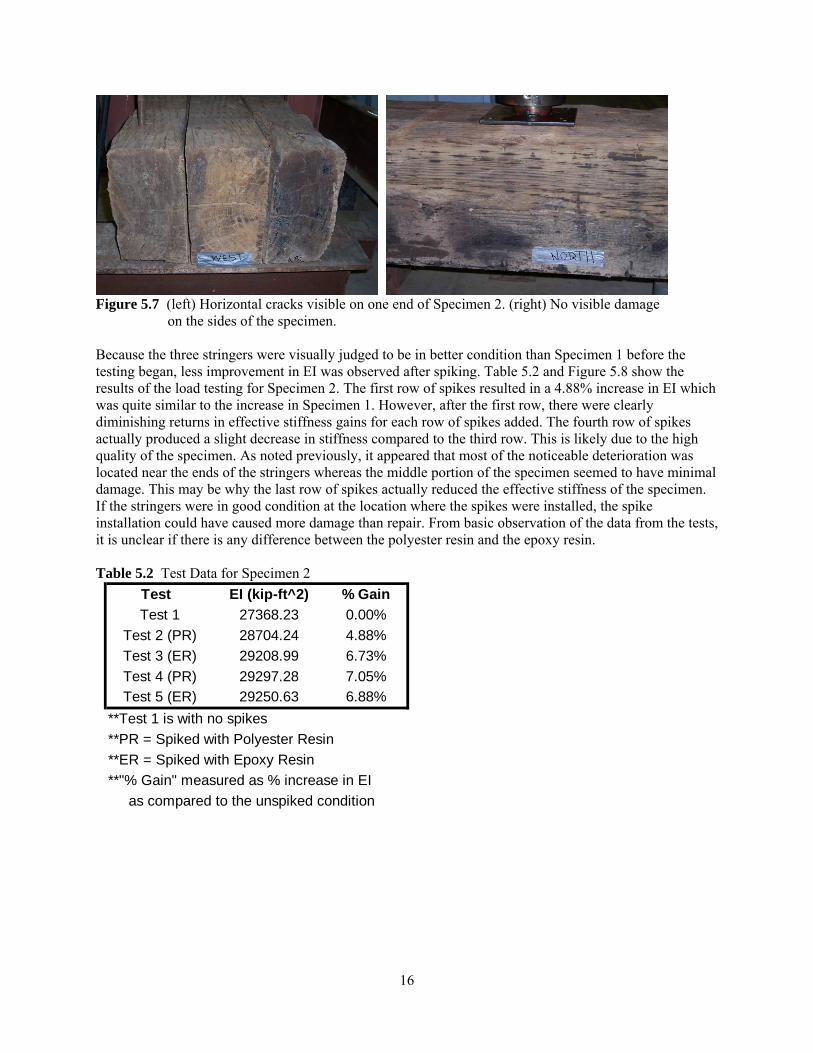
Figure 5.6 Spike layout for Specimen 2 Figure 5.7 shows the condition of Specimen 2. The stringers in the chord appeared to be in better condition than Specimen 1. There were no major visible cracks across the length of the specimen. However, there were some visible cracks on one end.
16
Figure 5.7 (left) Horizontal cracks visible on one end of Specimen 2. (right) No visible damage
on the sides of the specimen. Because the three stringers were visually judged to be in better condition than Specimen 1 before the testing began, less improvement in EI was observed after spiking. Table 5.2 and Figure 5.8 show the results of the load testing for Specimen 2. The first row of spikes resulted in a 4.88% increase in EI which was quite similar to the increase in Specimen 1. However, after the first row, there were clearly diminishing returns in effective stiffness gains for each row of spikes added. The fourth row of spikes actually produced a slight decrease in stiffness compared to the third row. This is likely due to the high quality of the specimen. As noted previously, it appeared that most of the noticeable deterioration was located near the ends of the stringers whereas the middle portion of the specimen seemed to have minimal damage. This may be why the last row of spikes actually reduced the effective stiffness of the specimen. If the stringers were in good condition at the location where the spikes were installed, the spike installation could have caused more damage than repair. From basic observation of the data from the tests, it is unclear if there is any difference between the polyester resin and the epoxy resin. Table 5.2 Test Data for Specimen 2
Test EI (kip-ft^2) % Gain0 Test 1 27368.23 0.00%1 Test 2 (PR) 28704.24 4.88%2 Test 3 (ER) 29208.99 6.73%3 Test 4 (PR) 29297.28 7.05%4 Test 5 (ER) 29250.63 6.88%3 **Test 1 is with no spikes4 **PR = Spiked with Polyester Resin
**ER = Spiked with Epoxy Resin**"% Gain" measured as % increase in EI as compared to the unspiked condition

17
0.00%
4.88%
6.73% 7.05% 6.88%
0.00%
1.00%
2.00%
3.00%
4.00%
5.00%
6.00%
7.00%
8.00%
0 1 2 3 4
Perc
ent G
ain
in E
I
Rows of Spikes
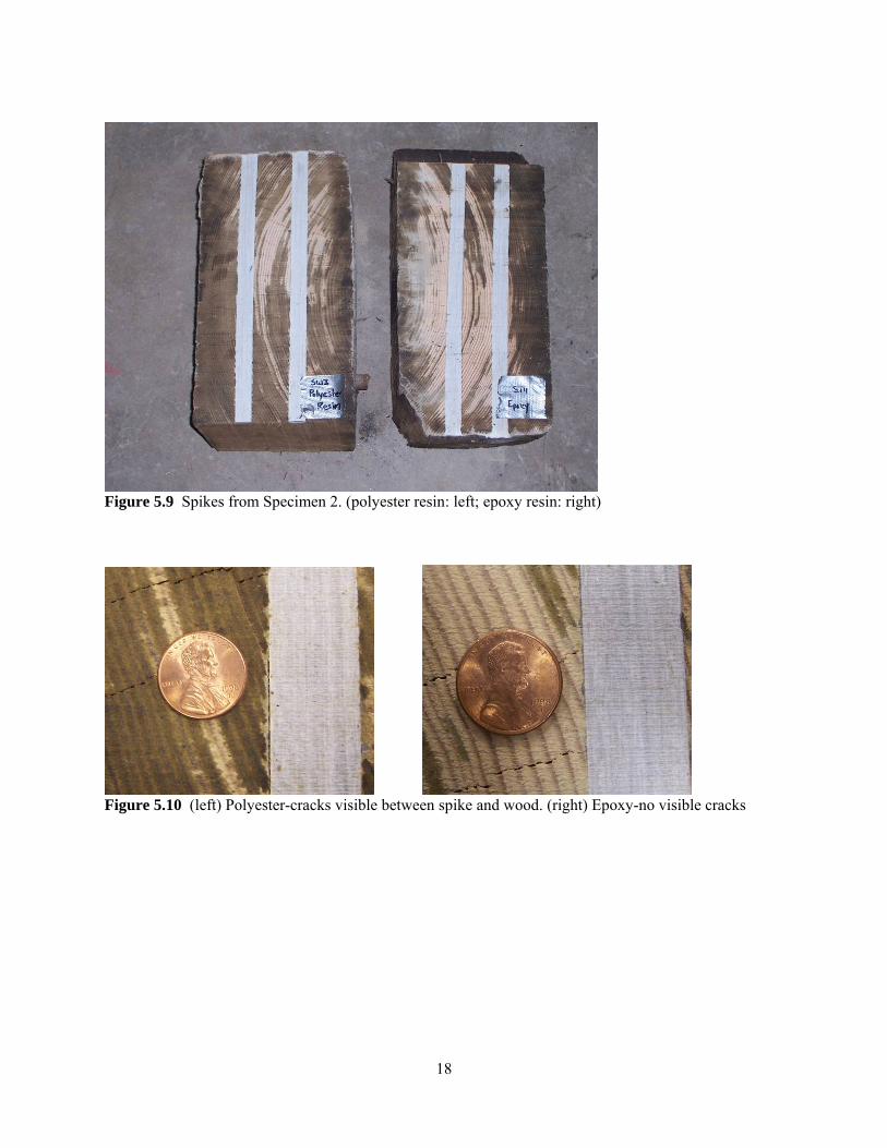
Figure 5.8 Percent gain in effective stiffness versus number of rows of spikes added to Specimen 2 It should be noted that Specimen 2 was not loaded to failure. Based on the results from the failure test of Specimen 1, it was determined that the actuator did not have the capacity to break Specimen 2. Rather, the specimen was cut apart after all increments of spikes had been installed so that the bonds of the polyester resin and epoxy resin could be viewed. It was possible that the failure testing from Specimen 1 had caused the bonds of the polyester resin to be broken. Specimen 2 allowed the bonds to be compared even before failure level loads had been applied to the specimen. Cuts were made on the west end of the south stringer in the chord. There, each of the four rows of spikes was examined (see Figure 5.9 and 5.10). All of the spikes had been bonded in place as desired. The spikes were solidly held in place and did not fall out of the specimen as they had in Specimen 1. However, upon closer inspection of the spikes, there were some clear differences between the polyester resin and the epoxy. The spikes that had been inserted with polyester resin exhibited some very small gaps that could be seen between the spikes and wood. This indicated regions where the adhesive had not fully bonded the spike and the wood. The epoxy specimens did not have any gaps indicating that a more complete bond had been achieved using the epoxy. Figure 5.10 shows the bond formed by each adhesive and the gaps visible in the polyester specimen. It appeared as though the revisions to the spiking process improved the bond between the spikes and the wood. However, it was concluded that the bonding of the epoxy resin was superior to that of the polyester resin. This may also suggest that the debonding seen in Specimen 1 was in part due to the cutting process since the bonds with the polyester resin were weaker.
18
Figure 5.9 Spikes from Specimen 2. (polyester resin: left; epoxy resin: right)
Figure 5.10 (left) Polyester-cracks visible between spike and wood. (right) Epoxy-no visible cracks

19
5.2.1 Specimen Drying Once Specimen 2 had been cut apart, it was observed that the polyester resin had not made a complete bond between the wood and the shear spike as evidenced by hairline cracks between the spikes and the wood. The epoxy had not demonstrated these cracks and appeared to have made a complete bond between the surfaces of the wood and the spikes. To examine the bond more thoroughly, the specimens were oven dried at 180°F to determine the effect of drying and heating the specimens. This was done to examine how changes in moisture content of the wood might impact the bond between the spike and wood. This drying test was a worst case scenario in which the wood was dried to near 0% water content. The expectation was that as the specimens dried, existing cracks would grow, and new cracks would develop. The specimens for the drying were cut from a segment of Specimen 2 similar to that shown in Figure 5.9. The sections shown were cut with a thickness of approximately two inches, and then the sections were cut in fourths. This was done in such a way that there were four samples that had the epoxy resin adhesive and four samples that had the polyester resin adhesive. The specimens were placed in the oven and observed periodically. At the beginning of the testing, specimens were observed every half hour. After two and a half hours of drying, they were only checked every hour. The specimens were dried for a total of nine and one half hours. Figure 5.11 shows pictures of one of the polyester resin specimens taken before and after the drying cycle. The picture on the left is the condition before the drying. The specimen exhibited small cracks along the surface between the spike and the wood. Also shown in the picture, the spike slightly overhangs the right edge of the wood specimen. When the specimens were cut, this would have been a flat surface. This suggests that in the few days between cutting the specimens and starting the drying, the specimens had already dried and shrunk as they were exposed to the environment. The bond between the spike and wood appeared nonexistent at least near the end where the spike and wood are separated.
Figure 5.11 Polyester resin drying specimen (left: before drying; right: after drying) The picture on the right in Figure 5.11 is of the same specimen of the polyester resin adhesive after the drying cycle. The primary visual difference shown in the picture is that the specimen shrunk more as it dried and pulled away from the spike more. There is much more overhang visible on the left end. In the end, the spike extended 1/16" to 1/8" past the end of the specimen. Looking also at the end of the specimen (Figure 5.12), separation can be seen between the spike and the wood. Clearly, the bond has been broken between the spike and wood. All of the specimens tested with the polyester resin exhibited similar behavior after drying.

20
Figure 5.12 End view of dried polyester resin specimen In the specimens that used the epoxy resin, there is evidence that the adhesive was bonded more completely. Figure 5.13 shows photographs of one specimen. The picture on the left shows the specimen before the drying. No cracks were evident between the spikes and the wood. Some checking can be seen on the surface of the specimen. It is possible that in the time between the cutting of the specimen and the drying test, the specimen may have started to dry. If there is a good bond between the spike and the wood, the spike will resist the shrinkage of the wood caused by drying. This would cause the checking that is seen. Also, the end of the specimen is smooth which indicates that there is still a complete bond. The picture on the right below shows the specimen after the drying cycle. No major change is observable between these two specimens except that the checking cracks appear to be larger. This would have resulted from the specimen drying more and the shrinkage being resisted by the spikes. It is concluded that in this specimen the epoxy held well initially and maintained its bond through the drying process.
Figure 5.13 Epoxy resin drying specimen (left: before drying; right: after drying) Not all epoxy resin specimens performed as well as the first one discussed. Two of the four specimens tested exhibited some cracking of the adhesive near the ends of the specimens. This allowed separation between the spikes and wood, and the wood was able to contract a little, meaning that there was less visible checking. As seen in Figure 5.14, there is some overhang in the epoxy specimen. However, the checking cracks were still present indicating that the epoxy was still maintaining its bond along most of the specimen in question.

21
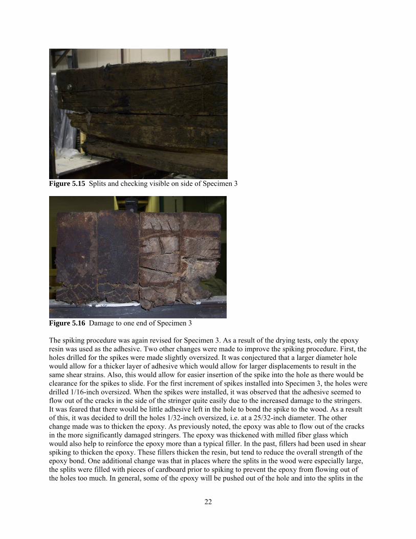
Figure 5.14 End view of epoxy specimen after drying The primary conclusion that can be drawn from this drying testing is that the bond formed by the epoxy resin is clearly better than the bond of the polyester resin. The only advantage the polyester resin offers is being less expensive. This benefit does not outweigh the disadvantage of the weaker bond strength. Thus, throughout the rest of this project, all spiking was done with the epoxy resin. It should be noted that this drying test was a material test only. The specimens were thin and the spikes exposed. They were completely dried to 0% moisture content. The preceding conditions would not occur in actual railroad members. The spikes are embedded far into the interior of a very wide member. Thus, it is unlikely that the checking seen in these dried specimens would occur in practice. The moisture conditions at points well within a typical large size member would not be near this extreme if the member was exposed to typical wetting and drying conditions on the exterior. 5.3 Specimen 3 Lastly, Specimen 3 was tested. This chord had substantial damage. There were large cracks on the sides of the chord and splitting in all stringers in the chord could be seen from the ends of the chord. Representative damage to the chord can be seen in Figures 5.15 and 5.16. Being the most damaged chord, this specimen was expected to have the most to gain from the spiking process.
22
Figure 5.15 Splits and checking visible on side of Specimen 3
Figure 5.16 Damage to one end of Specimen 3 The spiking procedure was again revised for Specimen 3. As a result of the drying tests, only the epoxy resin was used as the adhesive. Two other changes were made to improve the spiking procedure. First, the holes drilled for the spikes were made slightly oversized. It was conjectured that a larger diameter hole would allow for a thicker layer of adhesive which would allow for larger displacements to result in the same shear strains. Also, this would allow for easier insertion of the spike into the hole as there would be clearance for the spikes to slide. For the first increment of spikes installed into Specimen 3, the holes were drilled 1/16-inch oversized. When the spikes were installed, it was observed that the adhesive seemed to flow out of the cracks in the side of the stringer quite easily due to the increased damage to the stringers. It was feared that there would be little adhesive left in the hole to bond the spike to the wood. As a result of this, it was decided to drill the holes 1/32-inch oversized, i.e. at a 25/32-inch diameter. The other change made was to thicken the epoxy. As previously noted, the epoxy was able to flow out of the cracks in the more significantly damaged stringers. The epoxy was thickened with milled fiber glass which would also help to reinforce the epoxy more than a typical filler. In the past, fillers had been used in shear spiking to thicken the epoxy. These fillers thicken the resin, but tend to reduce the overall strength of the epoxy bond. One additional change was that in places where the splits in the wood were especially large, the splits were filled with pieces of cardboard prior to spiking to prevent the epoxy from flowing out of the holes too much. In general, some of the epoxy will be pushed out of the hole and into the splits in the

23
wood. This is desirable as it serves as an additional form of repair. However, it is undesirable for the epoxy to flow completely out of the stringers where it cannot bond to anything. It is important to keep all of the epoxy in the stringer and ensure there is a sufficient amount of epoxy remaining for the spike to bond to the wood in the hole. Once the spike was installed, the cardboard pieces were removed. In practice, one would have to consider filling these gaps with a suitable substance. The spike placement in the chord was slightly revised from the previous chords. The spacing used can be seen in the spiking layout shown in Figure 5.17. In this case, the original crosstie placement was visible on top of the specimen. The spike placement was changed so there was one row of spikes between each crosstie. This was done to be consistent with how the spiking process would likely be used in the field. This resulted in a spike spacing of 17.5 inches for the final specimen. Also, because the spacing of the spikes was determined by the crosstie spacing, the spikes are not placed symmetrically relative to midspan. There are 19.5 inches between the end support and the first spike on the south end and 14 inches on the north end. This chord was again spiked incrementally. The first increment was on the south end of the east side exterior stringer where some of the most significant damage was located. The next two increments finished repairing the east stringer of the chord. Next, the ends of the west side exterior stringer were repaired followed by the interior of the west ply. The same procedure was used for the repairing the middle-west and middle-east plies of the chord in that order. This resulted in nine increments in the spiking. Figure 5.17 shows the test set up for this specimen as well as the layout of the spikes as they were installed.
North
W
S
E
151
175.00"
8.00"
17.00" 16.00"
19.50"14.00"17.50"TYP
7.50"30.00"
Figure 5.17 Specimen 3 spike layout

24
Figure 5.18 also shows the increases in EI that were seen with each increment of spiking. Each of the nine spike increments resulted in an increase in the magnitude of EI. The last increment of spikes resulted in a minimal increase in the EI so it was decided that there was little reason to add any more spikes. Also, all of the expected places to install spikes had been used which is likely what the railroad would do in actual use of the spiking procedure. The results of the spiking of Specimen 3 were very positive. This was the most damaged specimen, and it clearly had the most to gain from the spiking procedure. The total percent increase in EI for this specimen was 267%. This is far larger than the increases seen in either Specimen 1 or 2. This is a direct result of the amount of damage originally present in each of the specimens.
0.00%
30.0%36.7% 37.4%
112%
134%
180%
199%
265% 267%
0%
50%
100%
150%
200%
250%
300%
0 1 2 3 4 5 6 7 8 9
Perc
ent I
ncre
ase
in E
ffec
tive
Stiff
ness
Test Number
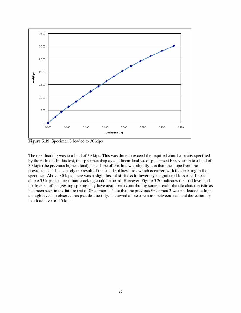
Figure 5.18 Percent increase in EI for Specimen 3 Once the spiking was completed, the specimen was loaded to 39 kips. This was done to surpass the rated load that is specified by the railroad and demonstrate the effectiveness of spiking at higher loads. The previous load tests had only been done to 15 kips which is a low load level for the railroad. The results of the test are shown in Figures 23 through 25. First, the specimen was loaded to 30 kips. The chord performed without incident up to a load of about 24 kips when some minor cracking could be heard. Above this point, there was a small loss of stiffness as the specimen began to deflect more. It is unknown what the cause of the cracking sounds was. Specimen 3 had significant damage which included some large voids in the wood. The cracking sounds may have had to do with these large voids and the epoxy in them as the chords settled under loads which were higher than in any previous test. As the chord continued to be loaded, there was a loud crack at a load of 30 kips. Because of the loud crack, the specimen was unloaded, and the chord was inspected for signs of damage to the wood and spikes. There were no visible results from the cracking, so testing was resumed.
25
0.00
5.00
10.00
15.00
20.00
25.00
30.00
35.00
0.000 0.050 0.100 0.150 0.200 0.250 0.300 0.350
Load
(kip
)
Deflection (in)
Figure 5.19 Specimen 3 loaded to 30 kips The next loading was to a load of 39 kips. This was done to exceed the required chord capacity specified by the railroad. In this test, the specimen displayed a linear load vs. displacement behavior up to a load of 30 kips (the previous highest load). The slope of this line was slightly less than the slope from the previous test. This is likely the result of the small stiffness loss which occurred with the cracking in the specimen. Above 30 kips, there was a slight loss of stiffness followed by a significant loss of stiffness above 35 kips as more minor cracking could be heard. However, Figure 5.20 indicates the load level had not leveled off suggesting spiking may have again been contributing some pseudo-ductile characteristic as had been seen in the failure test of Specimen 1. Note that the previous Specimen 2 was not loaded to high enough levels to observe this pseudo-ductility. It showed a linear relation between load and deflection up to a load level of 15 kips.

26
0.00
5.00
10.00
15.00
20.00
25.00
30.00
35.00
40.00
45.00
0.000 0.100 0.200 0.300 0.400 0.500 0.600
Load
(kip
)
Deflection (in)
Figure 5.20 Specimen 3 loaded to 39 kips After the chord had been loaded to 39 kips, one more load test was done. This test was intended to determine the EI for the chord after the high load tests were completed. It was observed during the 39 kip and 30 kip load tests that under the high loads, there was some stiffness loss. An additional test to 10 kips was done to determine the EI for Specimen 3 after concluding the load tests to higher load levels. The results of the 10 kip load test are shown in Figure 5.21.
0.00
2.00
4.00
6.00
8.00
10.00
12.00
0.000 0.020 0.040 0.060 0.080 0.100 0.120 0.140
Load
(kip
)
Deflection (in)
Figure 5.21 Specimen 3 loaded to 10 kips after high load tests

27
In order to compare the results of the three load tests and the changes in the effective stiffness as a result of those tests, Figure 5.22 has been included to show the plots of the load versus deflection data for each of the tests together. The small decreases in stiffness are evident from the decreasing slope of the data.
0.00
5.00
10.00
15.00
20.00
25.00
30.00
35.00
40.00
0.000 0.100 0.200 0.300 0.400 0.500 0.600
Load
(kip
)
Deflection (in)
30 kip load test
39 kip load test
10 kip load test
Figure 5.22 Specimen 3 load tests to 30 kips, 39 kips, and 10 kips plotted together It appears that the initial gains in EI from spiking may have been slightly optimistic. After loading, the EI was shown to be 37080 k-ft2 which is down from 48860 k-ft2 which was the maximum EI achieved after spiking. Even though there was a decrease from the maximum, the final EI was 179% greater than the initial EI. This is still a very significant increase. It is anticipated that additional load tests to 39 kips would demonstrate a linear relationship with an EI very similar to the EI from the 10 kip load test. Even with the loss in stiffness that was seen following the higher load tests, the spiking procedure was shown to be very effective in repairing the damaged specimens and regaining stiffness. Figure 5.23 shows the drop of in EI after the completion of the load tests. Test 10 in the figure is the load test to 10 kips after the 39 kip load test. As can be seen, there was a notable drop in EI after the final load test, but it is still a significant increase over the initial EI of the specimen. It is also unknown as to whether the original damaged member without spikes could have even resisted the 39 kip load. Instead, it had likely been removed because of concern it could not sustain such as load for a railroad bridge.

28
0%
30% 37% 37%
112%
134%
180%
199%
265% 267%
179%
0.00%
50.00%
100.00%
150.00%
200.00%
250.00%
300.00%
0 1 2 3 4 5 6 7 8 9 10
Perc
ent I
ncre
ase
in E
ffec
tive
Stiff
ness
Test Number
Figure 5.23 Percent increase in EI for Specimen 3 including test 10

29
6. RECOMMENDATIONS AND CONCLUSIONS As a result of the preceding tests, it has been determined that shear spiking is effective in repairing naturally deteriorated railroad bridge chords. The tests have shown varying degrees of improvement, but overall it has been seen that heavily damaged stringers can experience significant increases in effective stiffness. Several details of the spiking process have also been examined:
• Epoxy resin is the preferred adhesive. Tests performed with an alternative polyester resin showed that the epoxy formed a stronger, more complete, bond with the wood, resulting in increased strength. This increase in bond strength tends to offset the higher cost of the epoxy as compared to the polyester resin.
• The spiking process has been improved. By lightly sanding the spikes before their insertion, there
is a much better bonding surface which results in better bonding between the adhesive and the wood. A slightly oversized hole allows for a thicker layer of epoxy between the wood and the spikes as well as making it easier to insert the spikes. Using milled fiberglass as filler thickens the epoxy so that it can better fill voids in the heavily damaged stringers while not decreasing the strength of the epoxy.
• The effectiveness of the spiking procedure will be dependent upon the initial condition of the stringers being repaired. In this study, it was observed that there is a minor gain in effective stiffness in specimens with little existing damage. Conversely, very large, 267%, increases in effective stiffness were seen in the case where the stringers started in very poor condition and were load tested to 15 kips. After a loading it to 39 kips, the increase in stiffness relative to the initial dropped to 179%. This is still a very significant increase in EI and without spikes, the member’s ability to resist a 39 kip load is suspect.
As a result of the study, there are a number of recommendations or considerations for future testing. Results of this study suggest that the shear spiking technique should be explored in the field in an existing bridge. The performance of the spikes under actual train loads should be studied. Actual railcar loading will provide impact loads and will move across the length of the chords, and the performance of the spiking under these loads should be observed. Also, it is necessary that the rate of curing of the epoxy be studied. The epoxy/hardener combination currently used provides a cure time of 10-15 hours for a thin film at room temperature, approximately 72°F. Manufacturer information indicates that full strength of the epoxy is achieved in one to four days. This was confirmed in the study done by Radford1-4 which found that there were small increases in stiffness up to 6 days after the spikes were first installed. The spiking process is not intended to shut down a bridge for that amount of time. It is highly desirable that the repair work be able to be done between trains without changing the schedule of the rail line at all. Consequently, a laboratory study to examine the curing of the epoxy as a function of time is ongoing. The testing will involve installing an increment of spikes and doing load tests at varying increments of time starting just two or three hours after the installation of the spikes. The effective stiffness at the time increments will be observed to determine how the effective stiffness of the chord changes over time. Also, it should determine if the EI does increase with time and if disturbing the epoxy as it cures influences the final EI that is attainable from the spiking process. Again, this may need to be studied in the field with the repeated impact loads from the trains being applied to the chord as the epoxy cures. Also, additional testing should be done at higher load levels. In Specimen 3, it was observed that there was some loss in the EI of the specimen as loads surpassed 30 kips. Additional spiked specimens should be loaded to levels of 39 kips several times to ensure that this loss only corresponds to the first loading of the specimen to higher loads. In conjunction with this, new and damaged specimens could be loaded to 39

30
kips to observe the performance of both new and damaged specimens being loaded to high load levels. This would allow for a comparison between the performance of the spiked specimens with new and fully damaged specimens. It is thought that this testing would not require a large number of load cycles as Forsling, et al.13-15 already studied the effects of cyclic loading in spiked members. Finally, a study should be done to determine the impact of spikes on the maximum load capacity of railroad chord members in new or good condition. Although EI is not greatly affected, Specimens 1 and 3 gave an indication that the spikes may act as reinforcement in such specimens and provide increased ductility upon failure. If this is the case, spiking has the potential to be done on new specimens to aid in the performance of the specimens at failure.
31
7. REFERENCES 1. Radford, D. W., Peterson, M. L. & VanGoethem, D. “Composite Repair of Timber Structures,”
Report No. 00-112, Mountain-Plains Consortium, North Dakota State University, Fargo, ND; June 2000.
2. Radford, D. W., Gutkowski, R.M., VanGoethem, D. & Peterson, M. L. “Composite Repair of Timber
Bridges,” Proceedings 9th International Conference and Exhibition in Structural Faults and Repair, July 2001, ASCE, London, UK; 2001.
3. Radford, D. W., VanGoethem, D., Gutkowski, R.M. & Peterson, M. L. “Composite Repair of Timber
Structures,” Construction and Building Materials, Elsevier Publications, October 2002, pp. 417-425. 4. Radford, D. W., Gutkowski, R.M., VanGoethem, D. & Peterson, M. L. “Pultruded Composite Shear
Spike for Repair of Timber Members,” STREMAH 2003, Eighth International Conference on Structural Studies, Repairs and Maintenance of Heritage Architecture, Halkidiki, Greece, Wessex Institute of Technology, Southampton, UK, 2003, pp. 737-750.
5. Schilling, TJ. T. “Composite Repair of Railroad Crossties through the Process of Shear Spiking,”
M.S. Thesis, Department of Civil Engineering, Colorado State University, Fort Collins, CO; June 2004.
6. Schilling, TJ. T., Gutkowski, R.M. & Radford, D.W. “Composite Repair of Railroad Crossties
through the Process of Shear Spiking,” Report No. 04-163, Mountain-Plains Consortium, North Dakota State University, Fargo, ND; June 2004.
7. Gutkowski, R.M, Schilling, TJ. T. & Radford, D.W. “Composite Repair of Railroad Crossties by
Shear Spiking,” Proceedings 11th International Conference and Exhibition in Structural Faults and Repair, June 2006, ASCE, Edinburgh, Scotland, UK; 2006
8. Gutkowski, R.M. , Schilling, TJ T., Balogh, J. and Radford, D.W. 2008. FRP Z-Spike Repairing of
Wood Crossties, Journal of Structural Engineering, ASCE. Vol. 133, No. 2, pp. 1307-1315. 9. Burgers, T.A. “Composite Repair of Full-Scale Timber Bridge Chord Members through the Process
of Shear Spiking,” M.S. Thesis, Department of Civil Engineering, Colorado State University, Fort Collins, CO; May 2005.
10. Burgers, T.A., Gutkowski, R.M., Radford, D.W. & Balogh, J. “Composite Repair of Full-Scale
Timber Bridge Chord Members through the Process of Shear Spiking,” Report No. 05-173, Mountain Plains Consortium, North Dakota State University, Fargo, ND; December 2005.
11. T. Burgers, Gutkowski, R.M., Balogh, J., Radford, D. W. 2006, Shear Spike Repair of Timber
Railroad Bridge Chord Members, Proceedings, IABSE Symposium on Responding to Tomorrow’s Challenges in Structural Engineering, Budapest, Hungary.
12. Burgers, T.A., Gutkowski, R.M., Balogh, J. & Radford, D.W. 2008. “Repair of Full-Scale Timber
Bridge Chord Members by Shear Spiking,” ASCE, Journal of Bridge Engineering, Volume 13, No. 4, pp. 310-318.

32
13. Forsling, H. 2006. “Durability and Ultimate Flexural Loading of Shear Spike Repaired, Large-Scale Timber Railroad Bridge Members,” M.S. Thesis, Department of Civil Engineering, Colorado State University, Fort Collins, CO.
14. Gutkowski, R.M. & Forsling, H. “Durability and Ultimate Flexural Loading of Shear Spike Repaired,
Large-Scale Timber Railroad Bridge Members,” Report No. 07-190, Mountain Plains Consortium, North Dakota State University, Fargo, ND; December 2007.
15. Forsling, H, Gutkowski, R, Balogh, J & Radford, D. In review. “Load tests of Damaged Railroad
Timber Stringers Repaired by Shear Spiking,” Submitted to ASCE Journal of Structural Engineering. 16. “Pultruded Rod.” Liberty Pultrusions. 2007. <http://www.libertypultrusions.com/pulRods.htm> 17. "Product Guide." West System Epoxy. 14 Dec 2007. <http://westsystem.com/>. 18. “spec404.” US Composites. 20 March 2001. <http://www.uscomposites.com/specs/spec404.html>.