Embed Size (px)
Citation preview

Sandia is a multiprogram laboratory operated by Sandia Corporation, a Lockheed Martin Company, for the United StatesDepartment of Energy s National Nuclear Security Administration under contract DE-AC04-94AL85000.
Z-Pinch Inertial Fusion Energy
Craig L. Olson + Z-IFE TeamSandia National LaboratoriesAlbuquerque, NM 87185
Fusion Power AssociatesAnnual Meeting and SymposiumWashington, DCOctober 11-12, 2005
RTL LTD driver Z-PoP Chamber

The Z-Pinch IFE Team
Lead National Laboratory SNL
Collaborating National Laboratories: LLNL, LANL, NRL, LBNLCollaborating Universities:
UCB, U.Wisconsin, UCD, UCLA, Georgia-Tech, U. Missouri-Columbia, U. Alabama, UNM
Collaborating Industry: GA, ATK-MRC, SAIC, Omicron
Collaborating Institutions in Russia: Kurchatov Institute (Moscow)
Institute for High Current Electronics (Tomsk)
C. Olson, G. Rochau, S. Slutz, C. Morrow, R. Olson, A. Parker, M. Cuneo, Sanford, W.Stygar, R. Vesey, W. Varnum, T. Mehlhorn, K. Struve, M. Mazarakis, W. Fowler, R. Sharpe,S. Rogowski, M. Savage, A. Owen, T. Pointon, M. Kiefer, S. Rosenthal, L. Schneider, S.Glover, K. Reed, R. McKee, J. Jones, F. Long, L. Shipers, J. McDonald, P. Wakeland,C.Walker, G. Benevides, D. Schroen, E. Weinbrecht, W. Krych, C. Farnum, M. Modesto, D.Oscar, L. Chhabildas, W. Reinhart, J. Boyes, V. Vigil, R. Keith, M. Turgeon, B. Smith, B.Cipiti, S. Rodriguez, E. Lindgren, J. Cook, S. Durbin, A. Guild, J. Oakley, L. Perez, O.Rivera, D. Smith, K. Peterson, V. Dandini, D. McDaniel, J. Quintenz, M. Matzen, J. P.VanDevender, W. Gauster, L. Shephard, M. Walck, T. Renk, T. Tanaka, M. Ulrickson, P.Peterson, C. Debonnel, J. De Groot, N. Jensen, R. Peterson, G. Pollock, J. Grondalski, P.Ottinger, J. Schumer, D. Kammer, I. Golovkin, G. Kulcinski, L. El-Guebaly, G. Moses, E.Mogahed, I. Sviatoslavsky, M. Sawan, M. Anderson, R. Bonazza, R. Gallix, C. Charman, N.Alexander, W. Rickman, H. Tran, P. Panchuk, W. Meier, J. Latkowski, R. Moir, R. Schmitt, R.Abbot, S. Reyes, M. Abdou, A. Ying, P. Calderoni, L. Schmitz, N. Morley, S. Abdel-Khalik,M. Barkey, D. Welch, D. Rose, W. Szaroletta, R. Curry, K. McDonald, D. Louie, S. Dean, A.Kim, S. Nedoseev, E. Grabovsky, A. Kingsep, V. Smirnov

The long-term goal of Z-Pinch IFE is to produce an economicallyattractive power plant using high-yield z-pinch-driven targets( 3 GJ) at low rep-rate per chamber ( 0.1 Hz).
Z-Pinch IFE DEMO (ZP-3, the first study) used 12 chambers,each with 3 GJ at 0.1 Hz, to produce 1000 MWe
The near-term goal of Z-Pinch IFE is to address the science issues ofrepetitive pulsed power drivers, recyclable transmission lines, high-yield targets, and thick-liquid wall chamber power plants.
Considerable progress has been made towardthese goals, as will be reported in this talk
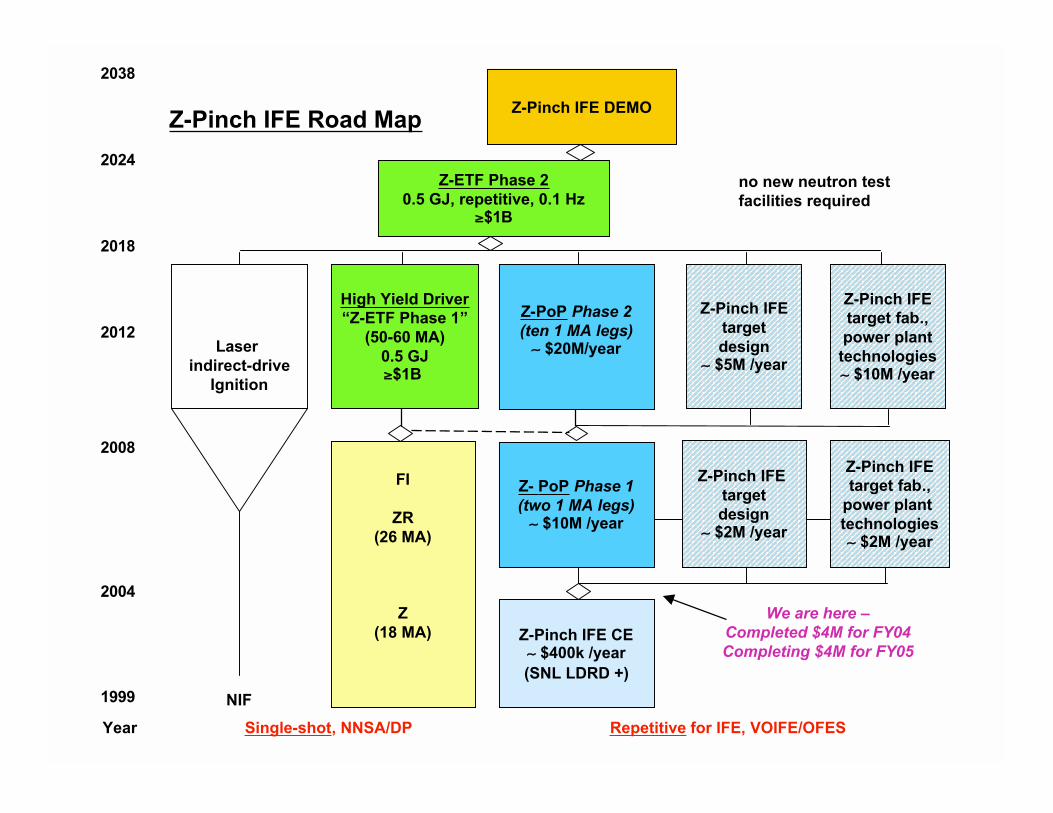
Z-Pinch IFE DEMO
Z-ETF Phase 20.5 GJ, repetitive, 0.1 Hz
$1B
Z-PoP Phase 2(ten 1 MA legs)
$20M/year
Z- PoP Phase 1(two 1 MA legs)
$10M /year
High Yield Driver“Z-ETF Phase 1”
(50-60 MA)0.5 GJ
$1B
Laser indirect-drive
Ignition
2038
2024
2018
2012
2008
2004
1999
FI
ZR(26 MA)
Z(18 MA)
NIF
Year Single-shot, NNSA/DP Repetitive for IFE, VOIFE/OFES
Z-Pinch IFE targetdesign
$2M /year
Z-Pinch IFEtarget fab.,
power plant technologies
$2M /year
Z-Pinch IFEtargetdesign
$5M /year
Z-Pinch IFEtarget fab.,power plant
technologies $10M /year
Z-Pinch IFE CE $400k /year
(SNL LDRD +)
Z-Pinch IFE Road Map
We are here –Completed $4M for FY04Completing $4M for FY05
no new neutron testfacilities required

Z-Pinch ICF with Z/ZR
(single shot)
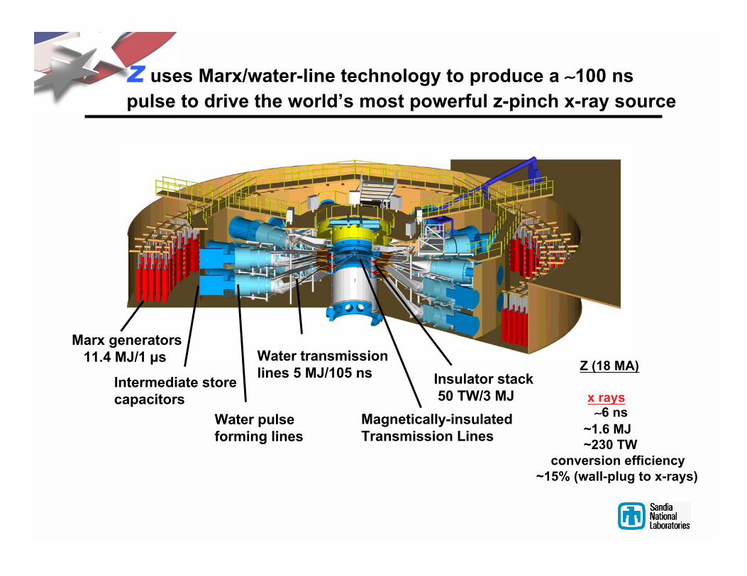
Z uses Marx/water-line technology to produce a 100 ns
pulse to drive the world’s most powerful z-pinch x-ray source
Marx generators 11.4 MJ/1 s
Intermediate storecapacitors
Water pulseforming lines
Water transmission lines 5 MJ/105 ns Insulator stack
50 TW/3 MJ
Magnetically-insulatedTransmission Lines
Z (18 MA)
x rays 6 ns
~1.6 MJ ~230 TW conversion efficiency~15% (wall-plug to x-rays)

ZR - Refurbishing the Entire Accelerator
OptimizeIntermediate Store
IncorporateModern Gas
Switch Design
OptimizeTransmission LinesUpgrade Power
Flow for HigherStresses, ImproveDiagnostic Access
Incorporate New LaserTriggering System
Improve DiagnosticsInfrastructure AccessReplace Capacitors -
Double Energy Stored
Optimize PulseForming Line &Water Switches
ZR (26 MA)
x rays ~2.7 MJ ~350 TW

ZR Project – Refurbishing Sandia’s Z machine -- the worlds
most powerful and energetic x-ray source for SSP applications
Balanced Objectives
with minimum impact to ongoing programs.
Cost effective refurbishment / optimization, realizing
6 Year Project
Total Cost (TPC) $90.4M
$61.7MDesign,
Engineering,Hardware
$28.7MR&D and
Installation
ZR - 2007
Z - 1996
Improved
Precision,
Flexibility
Higher
Capability-- Current
More
Capacity-- Shots
OPC TEC
September ‘05
Architecture Development
Single Module Design/Fab
Infrastructure Design/Fab
Single Module Testing
Production Design/Fab
Hardware Installation in Z
Testing
Schedule Reserve
FY02 FY03 FY04 FY05 FY06 FY07
CD3 CD4CD1 CD2CD0
0.001
0.01
0.1
1
10
1 10
En
erg
y (M
J/cm
)
Current (MA)
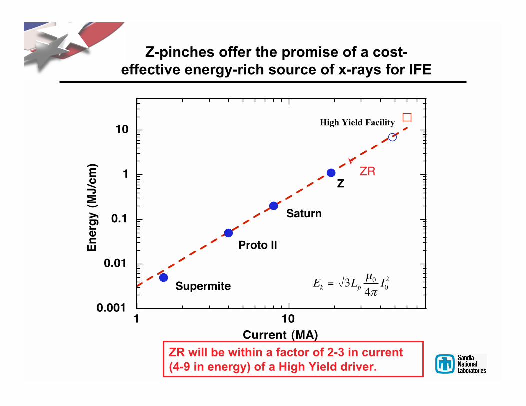
Z-pinches offer the promise of a cost-effective energy-rich source of x-rays for IFE
Supermite
Proto II
Saturn
Z
E L Ik p= 340
02µ
π
ZR
ZR will be within a factor of 2-3 in current(4-9 in energy) of a High Yield driver.
High Yield Facility
Z-Pinch IFE
(repetitive for energy)

Recyclable Transmission Line (RTL) Concept for Z-Pinch IFE
•Eliminates problems of final optic, pointing and tracking N beams, and high-speed target injection•Requires development of RTL
Thick
liquid
region
Thick
liquid
region
Structural wall
Upper
shielding
RTL
z-pinch
target
Connects to
pulsed power
driver
Yield and Rep-Rate: few GJ every 3-10 seconds per chamber (0.1 Hz - 0.3 Hz)Thick liquid wall chamber: only one opening (at top) for driver; nominal pressure (10-20 Torr)RTL entrance hole is only 1% of the chamber surface area (for R = 5 m, r = 1 m)Flibe absorbs neutron energy, breeds tritium, shields structural wall from neutronsNeutronics studies indicate 40 year wall lifetimesActivation studies indicate 1-1.5 days cool-down time for RTLsStudies of waste steam analysis, RTL manufacturing, heat cycle, etc. in progress

Z-Pinch IFE Power Plant has a Matrix of Possibilities
Repetitive Z-Pinch Driver: _
Marx generator/ magnetic switching linear transformer driver
water line technology (RHEPP technology) (LTD technology)
RTL (Recyclable Transmission Line): _
frozen coolant immiscible material
(e.g., Flibe/ electrical coating) (e. g., carbon steel)
Target: _
double-pinch dynamic hohlraum fast ignition
Chamber: _
dry-wall wetted-wall thick-liquid wall solid/voids
(e. g., Flibe foam)

Sandia is a multiprogram laboratory operated by Sandia Corporation, a Lockheed Martin Company, for the United StatesDepartment of Energy s National Nuclear Security Administration under contract DE-AC04-94AL85000.
Recent Results in Z-IFE
1. RTLs
simulations (5 MA/cm works)
experiments (5 MA/cm works)
pressure testing (20 Torr works)
2. LTD repetitive driver
0.5 MA, 100 kV cavity fires every 30 seconds
1.0 MA, 100 kV cavity tested
full IFE driver architectures
3. Shock mitigation
theory
experiments
simulations
4. Z-PoP planning
vacuum/electrical connections
overhead automation
animations/costing
5. Z-IFE targets for 3 GJ yields
gains 50-100
double-pinch/dynamic hohlraum
scaling studies
6. Z-IFE power Plant
RTL manufacturing/costing
wall activation studies: 40 year lifetime
power plant design

Recyclable Transmission Line (RTL) status/issues
RTL movement small acceleration – not an issueRTL electrical turn-on RTL experiments at 10 MA on SaturnRTL low-mass limit RTL experiments at 10 MA on SaturnRTL electrical conductivity RTL experiments at 10 MA on SaturnRTL mass handling comparison with coal plantRTL structural properties ANSYS simulations, buckling testsRTL shrapnel formation under studyRTL vacuum connections annular seal systemRTL electrical connections under studyRTL activation 1-1.5 day cool down timeRTL shock disruption to fluid walls experiments/simulations in progressRTL manufacturing/ cost ~$3 budget, current estimates: ~$5 for steel, $0.80 for Flibe
RTL inductance, configuration circuit code modeling in progressRTL power flow limits ALEGRA, LSP simulationsEffects of post-shot EMP, plasma, droplets, debris up the RTL – under study…
1. RTLs
On-goingResearch
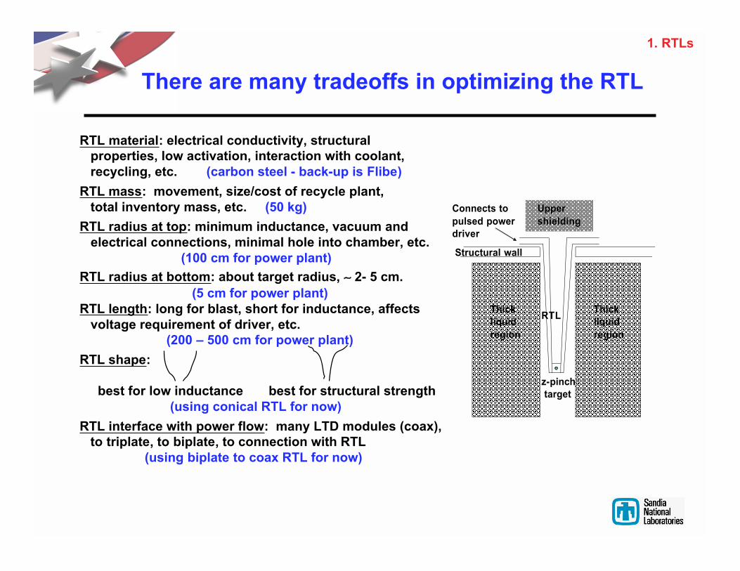
There are many tradeoffs in optimizing the RTL
Thick
liquid
region
Thick
liquid
region
Structural wall
Upper
shielding
RTL
z-pinch
target
Connects to
pulsed power
driver
RTL material: electrical conductivity, structural properties, low activation, interaction with coolant, recycling, etc. (carbon steel - back-up is Flibe)
RTL mass: movement, size/cost of recycle plant, total inventory mass, etc. (50 kg)
RTL radius at top: minimum inductance, vacuum and electrical connections, minimal hole into chamber, etc. (100 cm for power plant)
RTL radius at bottom: about target radius, 2- 5 cm.
(5 cm for power plant)RTL length: long for blast, short for inductance, affects voltage requirement of driver, etc. (200 – 500 cm for power plant)
RTL shape:
best for low inductance best for structural strength (using conical RTL for now)
RTL interface with power flow: many LTD modules (coax), to triplate, to biplate, to connection with RTL (using biplate to coax RTL for now)
1. RTLs

MITL/RTL Issues for 20 MA 60 MA 90 MA
(now on Z) (high yield) (IFE)
Issues that become most critical near the target:Surface heating, melting, ablation, plasma formationElectron flow, magnetic insulationConductivity changesMagnetic field diffusion changesLow mass RTL material moves more easilyPossible ion flow
I
20 MA
60 MA
90 MA
Rarray (z-pinch)
? 2 cm
? 2 cm
? 5 cm
I / (2 ?Rarray)
? 1.6 MA/cm
? 4.8 MA/cm
? 2.9 MA/cm
MITL
Works on Z
?
?
RTL
?
?
?
SNL, ATK-MRC, NRL, Kurchatov
ALEGRA MHD simulations ofthin-walled (0.6 mm thick),small AK gap (2 mm) at 60 MAshow no disruption at 5 MA/cm
Experiment on S-300 atKurchatov at 6 MA/cmshows plasma did notreconnect the MITL gap
Scaling of LSP simulations for 90MA at 2.9 MA/cm show acceptablecathode B field penetration (1-1.6µm/ns for 100 ns rise)
Present experiments and simulations indicate RTLs should work at 5 MA/cm or more
1. RTLs

RTLs made and pressure tested for structural strength:results compare favorably with code calculaions
• RTLs manufactured for tests
(radius 50 cm, length 200 cm,
thickness 0.635 mm)
• Pressure tests to buckling
(U. Alabama)
• Analysis
ANSYS (U. Wisconsin)
ABAQUS (SNL)
Singer Closed Form Solution
• Experiment results and coderesults predict buckling atabout 70 Torr (as anticipated)
• Chamber pressure of 10-20Torr has large safety margin
1. RTLs
Studies to make stronger andlighter RTLs (stiffners, variousshapes, etc.) under study

Linear Transformer Driver (LTD) technology iscompact and easily rep-rateable
•LTD uses parallel-charged capacitors in acylindrical geometry, with close multipletriggered switches, to directly driveinductive gaps for an inductive voltageadder driver (Hermes III is a 20 MV inductivevoltage adder accelerator at SNL)
•LTD requires no oil tanks or water tanks
•LTD accelerator volume about 1/4 -1/3 thevolume of Marx/water line technology (asused in Saturn and Z)
•LTD pioneered at Institute of High CurrentElectronics in Tomsk, Russia
Modular
High Efficiency
Low Cost (estimates are ~1/2 that for Marx/water line technology)
Easily made repetitive for 0.1 Hz
2. Repetitive Driver
h
h
center-line
LTD cell
Ferrite core
(isolates for V t)
Inductive voltage adder
cantilevered center electrode
one of N triggered
switches
one of M low-inductance
capacitors

Repetitive, 0.5 MA, 100-kV LTD Cavity in operation at SNL
This 0.5 MA cavity has exceeded 1000 shots in rep-rated mode at 0.03 Hz (one shot every 30 seconds)
2. Repetitive Driver
Average Peak Current:542 kA +/- 4.3kA
Average Rise Time:58.6 ns +/- 1.5 ns
Average FWHM:143.7 ns +/- 1.3 ns
Average Peak Current:542 kA +/- 4.3kA
Average Rise Time:58.6 ns +/- 1.5 ns
Average FWHM:143.7 ns +/- 1.3 ns
I (kA
)
t (s)
Overlay of 100 shots at 0.03 Hzfor 90 kV charging

-0.2
0
0.2
0.4
0.6
0.8
1
1.2
-20
0
20
40
60
80
100
120
0 200 400 600 800 1000
y
Iload (MA)
Vout(kV)
Iload
(M
A) V
ou
t(kV)
t(ns)
rise time = 70ns
-0.02
0
0.02
0.04
0.06
0.08
0.1
0.12
0.14
-2
0
2
4
6
8
10
12
14
0 200 400 600 800 1000
P(TW)
E(kJ)
P(T
W)
E(kJ)
t(ns)
1-MA, 100kV, 70ns LTD cavity ( top flange removed)
1.0 MA LTD cavity built - performs as expected during first 100 shots(this is the building block for Z-PoP and future Z-IFE drivers)
3-m
80 Maxwell 31165 caps,
40 switches, ±100 kV
0.1 Ohm load 0.1TW
2. Repetitive driver
SNL, Tomsk

An IFE driver with seventy 1-MA voltage adder modules,
each with 70 LTD cavities
0
20
40
60
80
100
0
2
4
6
8
10
0 50 100 150
g
Iload
(MA
)
Array K
E (M
J)
time (ns)
t = 95 ns
2. Repetitive driver
104 m
Power transmissionlines, MITLs
1 MA voltage addermodule
55 mg array load

90-MA IFE Driver (model 1) concept from the Kurchatov Institute, Moscow
2. Repetitive driver

Shock mitigation experiments in progress
Shock tube tests with Explosives with water curtain Foamed liquid sheetswater layers, Al foams
Shock tube facility at the Vacuum Hydraulics Experiment Georgia-TechUniversity of Wisconsin (VHEX) at UCB annular foamed jet
exploding wire creates shock
3. Shock mitigation
Two-Phase Annular Jets(OD = 5.2 cm; ID = 4.0 cm)
1% Void, 1 m/s 10% Void, 1 m/s 1% Void, 2 m/s 10% Void, 2 m/s

Shock mitigation code calculations in progress
3. Shock mitigation
ALEGRA simulation ofshocked Al metal foamsheet (SNL)
Flibe jet geometryfor shock mitigation(LLNL) - 3 GJ yieldcontained
Dyna2Dsimulations(GA)
Liquid walls
Foamed Flibe
Liquid pool
Bubbles
3. Shock mitigation

Z – PoP (two 1 MA legs)
Center chamber
Upper MezzanineScreen Room
Pallet Track
LTD Module and Stand
LTD RebuildStation
4. Z-PoP planning

Z – PoP (ten 1 MA legs)comparable to a rep-rated Saturn at 10 MA
4. Z-PoP planning

Z-PoP Movie4. Z-PoP planning

We are continuing to evaluate a diverseportfolio of ICF options for Z-pinch IFE
Gas fillCryogenic
Double shellFast ignitionHot spotignition
Magnetic field
Vacuumhohlraum
Dynamichohlraum
HybridHohlraum
Driver ICF Target
Indirectdrive
Directdrive
BeCu-Foam
Au/Cu
DT
Au
Be
NEW
5. Z-IFE targets

Z-pinch-driven-hohlraums have similar topology tolaser-driven-hohlraums, but larger scale-size
Double ended hohlraum
Laser SourceCones
NIF Scale
5.5 mm10 mm
35 mmDynamic hohlraum
6 mm
5. Z-IFE targets

We are exploring 2 complementary Z-pinch indirect-drivetarget concepts for high-yield ICF and Z-IFE
Double-EndedHohlraum
Dynamic Hohlraum
ICF _ IFE
2 x (62 – 116) MA
2 x (19 – 67) MJ
2 x (9 – 33) MJ
1.2 – 8.6 MJ
400 – 4500 MJ
56 – 95 MA
14 – 42 MJ
2.4 – 7.2 MJ
530 – 4600 MJ
Peak current
Energy delivered to pinches
Z-pinch x-ray energy output
Capsule absorbed energy
Capsule yield
Peak current
Energy delivered to pinch
Capsule absorbed energy
Capsule yield
J. Hammer, M. Tabak J. Lash, S. Slutz, R. Vesey
5. Z-IFE targets

PLUNGER
FLIBEJETS
CHAMBER
MOLTEN FLIBEPOOL
Transmission Lines to Linear Transformer PULSED POWER DRIVER
20 TorrInert Gas
Inert GasFlow for
ContaminationControl
CARTRIDGE
LARGE PARTICULATECOLLECTIONS
SYSTEM
POOL AND DEBRISMOMENTUMDIFFUSER
AIRLOCKS
BASE Z-IFE UNIT
6. Z-IFE Power Plant

RTL Operation
6. Z-IFE Power Plant

6. Z-IFE Power Plant

Z-Pinch Power Plant Baseline Parameters
Target Yield 3 GJRep. Rate (per chamber) 0.1 HzFusion Power per chamber 300 MWthNumber of Chambers 10
ChamberShape Spherical orEllipsoidalDimension 4 m internal radiusMaterial F82H SteelWall Thickness 15-30 cm
CoolantCoolant Choice FlibeJet Design Circular ArrayStandoff (Target to First Jet) 0-2 mVoid Fraction 0.05 – 0.67Curtain Operating Temperature 950 KAverage Curtain Coolant Flow 12 m3/sHeat Exchanger Coolant Flow 0.47 m3/sHeat Exchanger Temp. Drop 133 KPumping Power 1.3 MW/chamberHeat Cycle RankineHeat Exchanger Type Shell and Tube
Tritium RecoveryBreeding Ratio 1.1Tritium Recovered per Shot 0.017 g Extraction Type Countercurrent
RTLRTL Material 1004 Carbon SteelCone Dimensions 1 m Ø x 0.1 m Ø x 2 m hOuter Cone Thickness 0.9 mm _ 0.52 mmInner Cone Thickness 0.52 mmMass per RTL (2 cones) 50 kg _ 34 kg
RTL ManufacturingFurnace Electric ArcProduction Sheet Metal to Deep DrawEnergy Demand 184 MW for ten chambers
6. Z-IFE Power Plant

Sandia is a multiprogram laboratory operated by Sandia Corporation, a Lockheed Martin Company, for the United StatesDepartment of Energy s National Nuclear Security Administration under contract DE-AC04-94AL85000.
Z-Pinch Inertial Fusion Energy
RTL LTD driver Z-PoP Chamber
•Substantial progress is being made in all area of Z-Pinch IFE
•A growing Z-Pinch IFE program is envisioned