Embed Size (px)
Citation preview
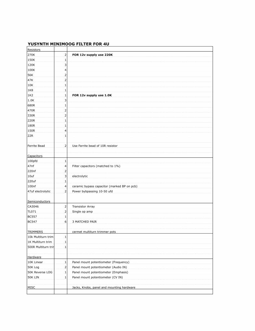
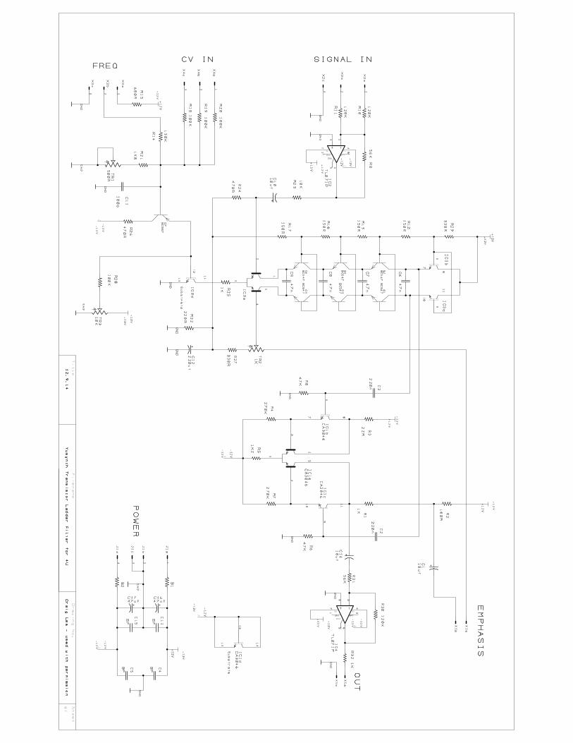
YUSYNTH MINIMOOG FILTER FOR 4UResistors
270K 2 FOR 12v supply use 220K
150K 1
120K 3
100K 4
56K 2
47K 2
10K 1
1K8 1
1K2 1 FOR 12v supply use 1.0K
1.0K 3
680R 1
470R 2
330R 2
220R 1
180R 1
150R 4
22R 1
Ferrite Bead 2 Use Ferrite bead of 10R resistor
Capacitors
100pfd 1
47nf 4 Filter capacitors (matched to 1%)
220nf 2
10uf 3 electrolytic
220uf 1
100nf 4 ceramic bypass capacitor (marked BP on pcb)
47uf electrolytic 2 Power bybpassing 10-50 ufd
Semiconductors
CA3046 2 Transistor Array
TL071 2 Single op amp
BC557 1
BC547 6 3 MATCHED PAIR
TRIMMERS cermet multiturn trimmer pots
10k Multiturn trim 1
1K Multiturn trim 1
500R Multiturn trim 1
Hardware
10K Linear 1 Panel mount potentiometer (Frequency)
50K Log 2 Panel mount potentiometer (Audio IN)
50K Reverse LOG 1 Panel mount potentiometer (Emphasis)
50K LIN 1 Panel mount potentiometer (CV IN)
MISC Jacks, Knobs, panel and mounting hardware
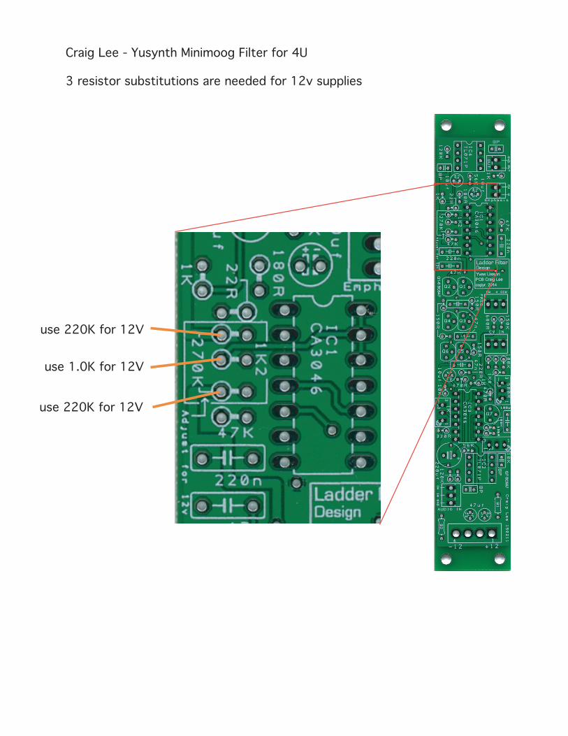
Craig Lee - Yusynth Minimoog Filter for 4U
3 resistor substitutions are needed for 12v supplies
use 220K for 12V
use 220K for 12V
use 1.0K for 12V
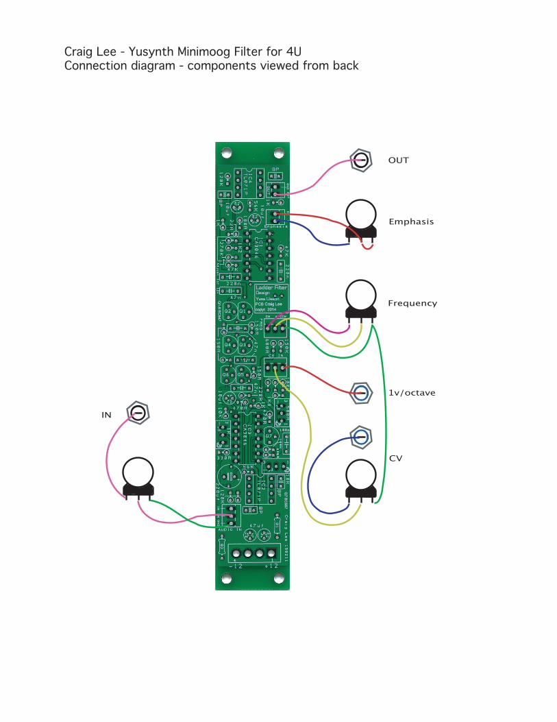
Craig Lee - Yusynth Minimoog Filter for 4UConnection diagram - components viewed from back
1v/octave
CV
Emphasis
OUT
IN
Frequency
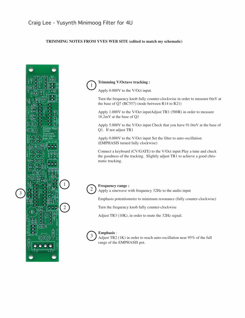
Craig Lee - Yusynth Minimoog Filter for 4U
TRIMMING NOTES FROM YVES WEB SITE (edited to match my schematic)
1
2
3 Emphasis :Adjust TR2 (1K) in order to reach auto-oscillation near 95% of the full range of the EMPHASIS pot.
Trimming V/Octave tracking : Apply 0.000V to the V/Oct input. Turn the frequency knob fully counter-clockwise in order to measure 0mV at the base of Q7 (BC557) (node between R14 to R21) Apply 1.000V to the V/Oct inputAdjust TR1 (500R) in order to measure 18.2mV at the base of Q1 Apply 5.000V to the V/Oct input Check that you have 91.0mV at the base of Q1. If not adjust TR1 Apply 0.000V to the V/Oct input Set the filter to auto-oscillation (EMPHASIS turned fully clockwise) Connect a keyboard (CV/GATE) to the V/Oct input Play a tune and check the goodness of the tracking. Slightly adjust TR1 to achieve a good chro-matic tracking.
Frequency range :Apply a sinewave with frequency 32Hz to the audio input Emphasis potentiometer to minimum resonance (fully counter-clockwise) Turn the frequency knob fully counter-clockwise Adjust TR3 (10K), in order to mute the 32Hz signal.
1
2
3