Embed Size (px)
Citation preview
1
2 POLYFLOW PIPES SDN BHD Company Profile
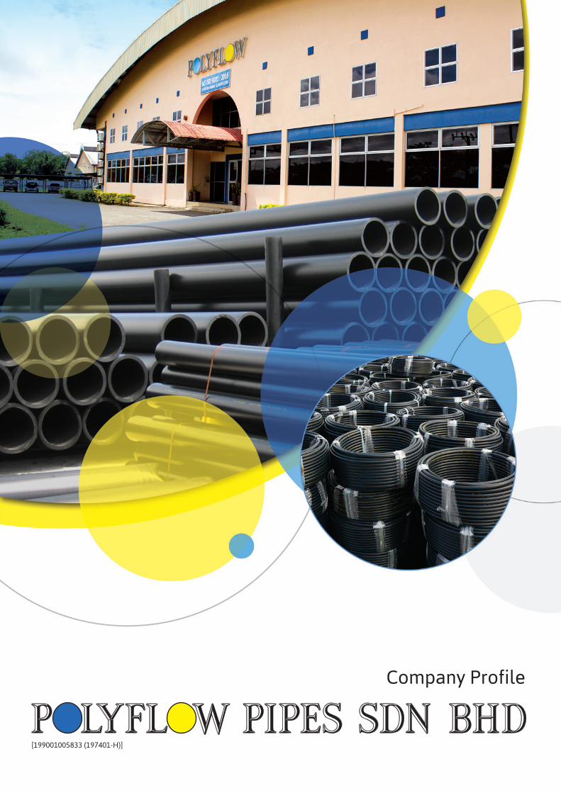
Polyflow Pipes Sdn Bhd was incorporated in 1990. lt manufactures Polyethylene (PE) pipes for use in : • Potable water distribution • Cable/communication protection pipe/conduit system • Gas distribution • Irrigation • Sewerageandeffluentdisposal • Chemicals pipes in factories
Currently, it is marketing under the brand name “POLYFLOW”. It is used widely by all the Sarawak Water Authorities. It is the pioneer in the manufacture of PE pipes in East Malaysia. The pipe sizes range from 20 mm to 500 mm outer diameter (OD). Customers can specify the pipes to have stripes of blue, red or orange for water distribution and cable/communication system protection respectively and yellow pipes for gas distribution. “POLYFLOW” pipes conform to MS1058 (Malaysian Standard for potable water HDPE pipes), ISO4427 (ISO Standard for potable water HDPE pipes), MS1086 (Malaysian Standard for gas PE pipes) & ISO4437 (ISO Standard for gas PE pipes). Polyflow Pipes SdnBhd is committed to quality assurance and customer satisfaction through our ISO9001 Certified Quality Management System. Polyflow Pipes Sdn Bhd is a wholly owned subsidiary of Quality Concrete Holdings Berhad which is a very diversified group of companies listed in the Kuala Lumpur Stock Exchange (Bursa Malaysia).
Your Trusted Polyethylene (PE) Pipes Manufacturer
1
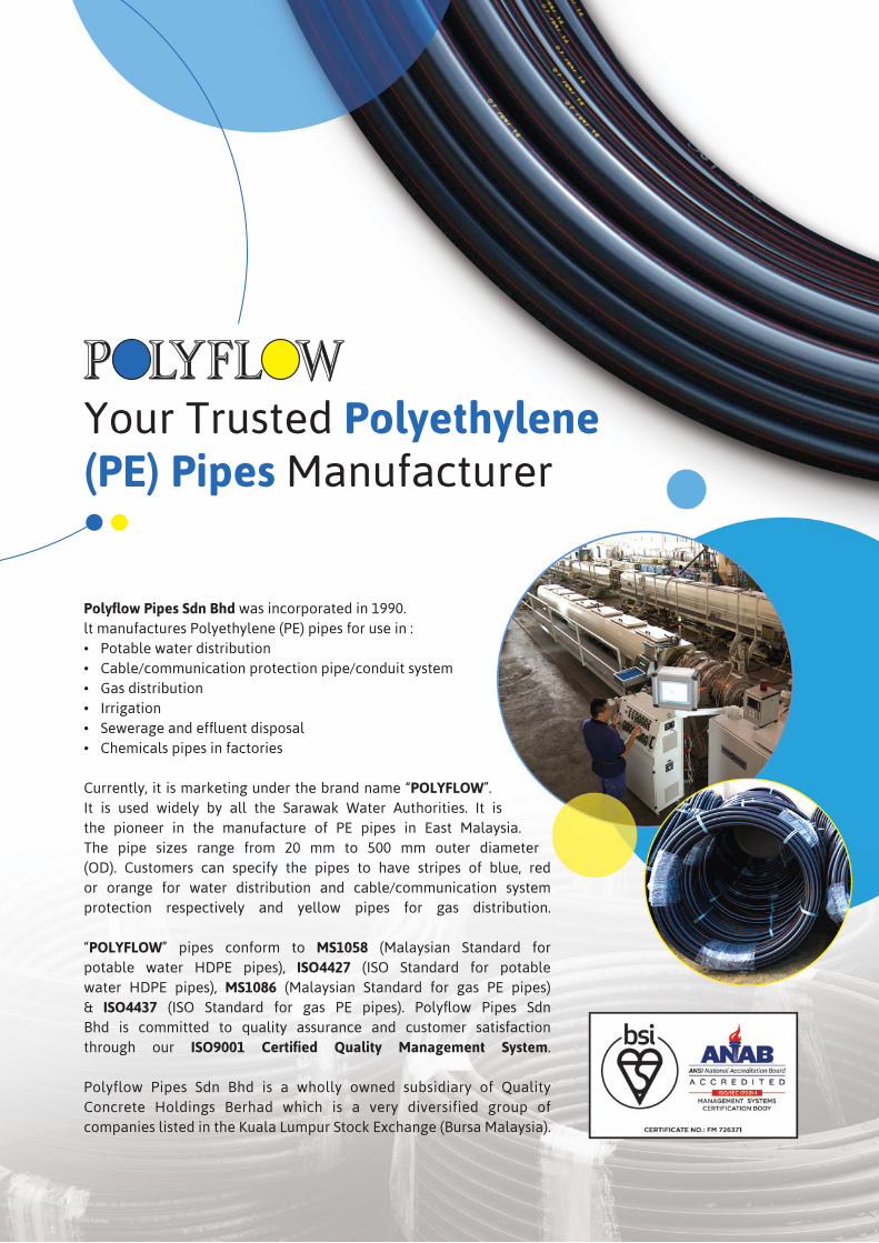
Our Products
WATERPE PIPES
CABLE/COMMUNICATION PE PIPES
GASPE PIPES
Blue Stripe Water Pipes(Straight lengths)
Blue Stripe Water Pipes(Coiled lengths)
Red/Orange StripeCable/Communication Pipes
(Straight lengths)
Red/Orange StripeCable/Communication Pipes
(Coiled lengths)
Yellow Gas Pipes(Straight lengths)
Yellow Gas Pipes(Coiled lengths)
FITTINGS
Push Fit Compression Fittings Tapping Saddles Fabricated Fittings
Electrofusion FittingsEnd Caps, Stub Ends and Flanges
1
2 POLYFLOW PIPES SDN BHD Company Profile
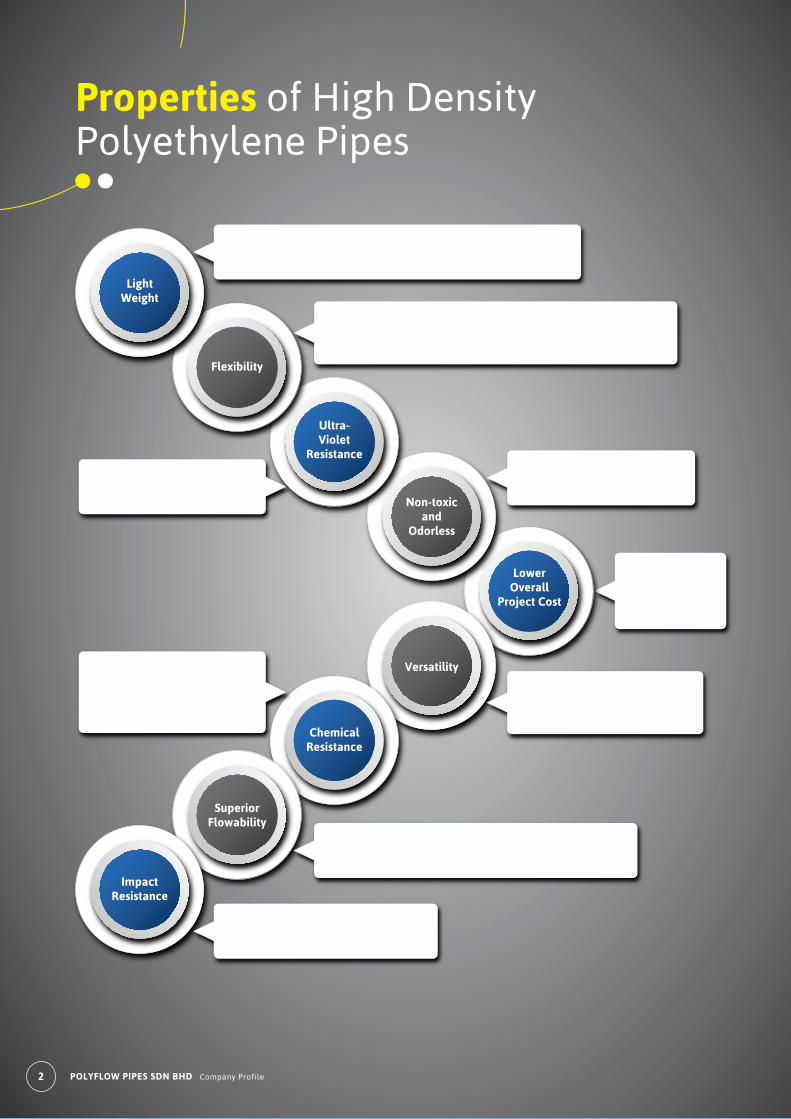
• The weight of PE pipe is only about 1/5 of a steel pipe of a similar size.• Easy handling.• Significant savings in costs of handling and transportation.
LowerOverall
Project Cost
Non-toxicand
Odorless
Versatility
Ultra-Violet
Resistance
ChemicalResistance
Flexibility
SuperiorFlowability
LightWeight
ImpactResistance
• Natural flexibility.• Can be bent to conform to terrain contours and soil movements.• Can be bent at a minimum radius of 25 to 40 times the pipe diameter.• Long length without joints.
• Polyflow PE Pipes are protected against Ultra-Violet radiation (sunlight).
• Physiologically harmless.• Free from toxicity and does not affect taste of drinking water.
• Lower overall cost results from all the good properties of PE Pipes.
• Superior physical and chemical- resistant properties.• Can be used in a large number of applications and industries.
• Good chemical resistance to most common organic and inorganic chemicals, from pH values of 0 to 14.• Resistant to rotting or rusting.
• PE Pipes have extremely smooth inner surface giving lowest flow resistance.• No scaling or corrosion encrustation.
• High flexural and impact strength.• Will not easily crack, break or fracture when handled roughly.
Properties of High Density Polyethylene Pipes
2 POLYFLOW PIPES SDN BHD Company Profile
3
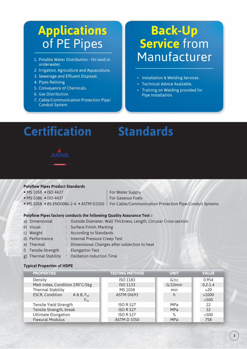
1. Potable Water Distribution - On land or underwater.
2. Irrigation, Agriculture and Aquaculture.
3. SewerageandEffluentDisposal.
4. Pipes Relining.
5. Conveyance of Chemicals.
6. Gas Distribution.
7. Cable/Communication Protection Pipe/ Conduit System.
Applicationsof PE Pipes
Back-UpService from
Manufacturer
• Installation & Welding Services.
• Technical Advice Available.
• Training on Welding provided for Pipe Installation.
Polyflow Pipes Product Standards• MS 1058 • ISO 4427 For Water Supply • MS 1086 • ISO 4437 For Gaseous Fuels • MS 1058 • BS EN50086-2-4 • ASTM D3350 For Cable/Communication Protection Pipe/Conduit Systems
Polyflow Pipes factory conducts the following Quality Assurance Test :-a) Dimensional : Outside Diameter, Wall Thickness, Length, Circular Cross-section b) Visual : Surface Finish, Marking c) Weight : According to Standards d) Performance : Internal Pressure Creep Test e) Thermal : Dimensional Changes after subjection to heat f) Tensile Strength : Elongation Test g) Thermal Stability : Oxidation Induction Time
Certification and Standards
Typical Properties of HDPE
PolyflowPipesSdnBhdQuality Management System of PE pipes manufacturing is certifiedtoISO9001 by British Standards Institution (BSI)
“Polyflow”WaterPipesarecertifiedby SIRIM QAS International Sdn Bhd
PROPERTIES TESTING METHOD UNIT VALUE
Density ISO 1183 G/cc 0.954 Melt Index, Condition 190˚C/5kg ISO 1133 G/10min 0.2-1.4 Thermal Stability MS 1058 min >20 ESCR, Condition A & B, F50 ASTM DI693 h >1000 F20 >500 Tensile Yield Strength ISO R 527 MPa 22 Tensile Strength, break ISO R 527 MPa 32 Ultimate Elongation ISO R 527 % >500 Flexural Modulus ASTM D 3350 MPa 758
3
4 POLYFLOW PIPES SDN BHD Company Profile
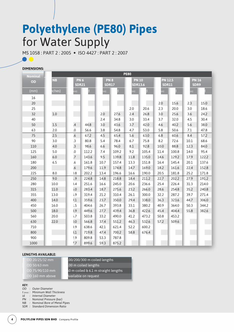
Polyethylene (PE80) Pipesfor Water SupplyMS 1058 : PART 2 : 2005 • ISO 4427 : PART 2 : 2007
KEY:OD : Outer Diametert (min) : Minimum Wall Thicknessid : Internal DiameterPN : Nominal Pressure (bar)NB : Nominal Bore of Metal PipesSDR : Standard Dimension Ratio
LENGTHS AVAILABLE:
OD 20/25/32 mm 100/200/300 m coiled lengths
OD 50/63 mm 100 m coiled lengths
OD 75/90/110 mm 50 m coiled & 6.1 m straight lengths
OD 160 mm above Available on request
DIMENSIONS:
Nominal
PE80
OD NB PN 6 PN 8 PN 10 PN 12.5 PN 16 SDR21 SDR17 SDR13.6 SDR11 SDR9
(mm) (inches) t (min) id t (min) id t (min) id t (min) id t (min) id
16
20 2.0 15.6 2.3 15.0
25 2.0 20.6 2.3 20.0 3.0 18.6
32 1.0 2.0 27.6 2.4 26.8 3.0 25.6 3.6 24.2
40 2.4 34.8 3.0 33.4 3.7 32.0 4.5 30.4
50 1.5 2.4 44.8 3.0 43.6 3.7 42.0 4.6 40.2 5.6 38.0
63 2.0 3.0 56.6 3.8 54.8 4.7 53.0 5.8 50.6 7.1 47.8
75 2.5 3.6 67.2 4.5 65.4 5.6 63.0 6.8 60.6 8.4 57.2
90 3.0 4.3 80.8 5.4 78.4 6.7 75.8 8.2 72.6 10.1 68.6
110 4.0 5.3 98.6 6.6 96.0 8.1 92.8 10.0 88.8 12.3 84.0
125 5.0 6.0 112.2 7.4 109.2 9.2 105.4 11.4 100.8 14.0 95.4
160 6.0 7.7 143.6 9.5 139.8 11.8 135.0 14.6 129.2 17.9 122.2
180 6.5 8.6 161.8 10.7 157.4 13.3 151.8 16.4 145.4 20.1 137.6
200 9.6 179.6 11.9 174.8 14.7 169.0 18.2 161.6 22.4 152.8
225 8.0 10.8 202.2 13.4 196.6 16.6 190.0 20.5 181.8 25.2 171.8
250 9.0 11.9 224.8 14.8 218.8 18.4 211.2 22.7 202.2 27.9 191.2
280 10.0 13.4 251.6 16.6 245.0 20.6 236.6 25.4 226.4 31.3 214.0
315 11.0 15.0 283.4 18.7 275.6 23.2 266.0 28.6 254.8 35.2 240.8
355 13.0 16.9 319.4 21.2 310.4 26.1 300.0 32.2 287.2 39.7 271.4
400 14.0 19.1 359.6 23.7 350.0 29.4 338.0 36.3 323.6 44.7 306.0
450 16.0 21.5 404.6 26.7 393.8 33.1 380.2 40.9 364.0 50.3 344.2
500 18.0 23.9 449.6 27.7 439.4 36.8 422.6 45.4 404.4 55.8 382.6
560 20.0 26.7 503.8 33.2 490.0 41.2 473.2 50.8 453.2
630 22.0 30.0 566.8 37.4 551.2 46.3 532.6 57.2 509.6
710 33.9 638.6 42.1 621.4 52.2 600.2
800 38.1 719.8 47.4 700.2 58.8 676.4
900 42.9 809.8 53.3 787.8
1000 47.7 899.6 59.3 875.2
5
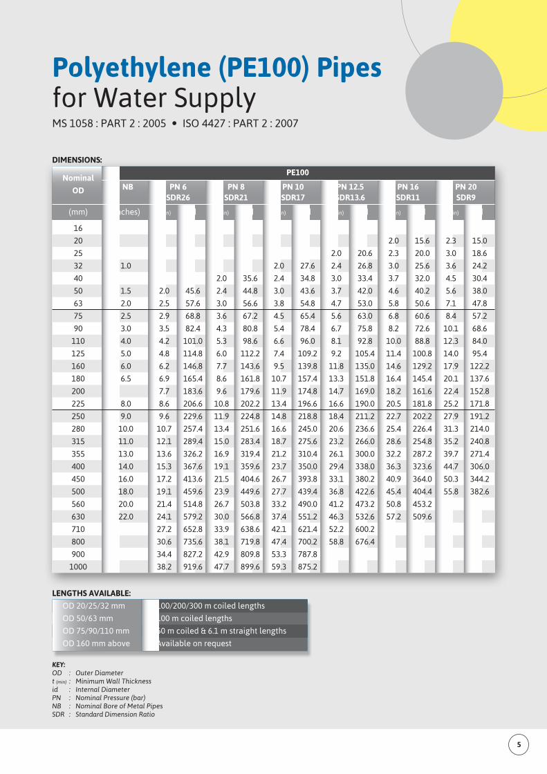
Polyethylene (PE100) Pipesfor Water SupplyMS 1058 : PART 2 : 2005 • ISO 4427 : PART 2 : 2007
KEY:OD : Outer Diametert (min) : Minimum Wall Thicknessid : Internal DiameterPN : Nominal Pressure (bar)NB : Nominal Bore of Metal PipesSDR : Standard Dimension Ratio
LENGTHS AVAILABLE:
OD 20/25/32 mm 100/200/300 m coiled lengths
OD 50/63 mm 100 m coiled lengths
OD 75/90/110 mm 50 m coiled & 6.1 m straight lengths
OD 160 mm above Available on request
DIMENSIONS:
Nominal
PE100
OD NB PN 6 PN 8 PN 10 PN 12.5 PN 16 PN 20 SDR26 SDR21 SDR17 SDR13.6 SDR11 SDR9
(mm) (inches) t (min) id t (min) id t (min) id t (min) id t (min) id t (min) id
16
20 2.0 15.6 2.3 15.0
25 2.0 20.6 2.3 20.0 3.0 18.6
32 1.0 2.0 27.6 2.4 26.8 3.0 25.6 3.6 24.2
40 2.0 35.6 2.4 34.8 3.0 33.4 3.7 32.0 4.5 30.4
50 1.5 2.0 45.6 2.4 44.8 3.0 43.6 3.7 42.0 4.6 40.2 5.6 38.0
63 2.0 2.5 57.6 3.0 56.6 3.8 54.8 4.7 53.0 5.8 50.6 7.1 47.8
75 2.5 2.9 68.8 3.6 67.2 4.5 65.4 5.6 63.0 6.8 60.6 8.4 57.2
90 3.0 3.5 82.4 4.3 80.8 5.4 78.4 6.7 75.8 8.2 72.6 10.1 68.6
110 4.0 4.2 101.0 5.3 98.6 6.6 96.0 8.1 92.8 10.0 88.8 12.3 84.0
125 5.0 4.8 114.8 6.0 112.2 7.4 109.2 9.2 105.4 11.4 100.8 14.0 95.4
160 6.0 6.2 146.8 7.7 143.6 9.5 139.8 11.8 135.0 14.6 129.2 17.9 122.2
180 6.5 6.9 165.4 8.6 161.8 10.7 157.4 13.3 151.8 16.4 145.4 20.1 137.6
200 7.7 183.6 9.6 179.6 11.9 174.8 14.7 169.0 18.2 161.6 22.4 152.8
225 8.0 8.6 206.6 10.8 202.2 13.4 196.6 16.6 190.0 20.5 181.8 25.2 171.8
250 9.0 9.6 229.6 11.9 224.8 14.8 218.8 18.4 211.2 22.7 202.2 27.9 191.2
280 10.0 10.7 257.4 13.4 251.6 16.6 245.0 20.6 236.6 25.4 226.4 31.3 214.0
315 11.0 12.1 289.4 15.0 283.4 18.7 275.6 23.2 266.0 28.6 254.8 35.2 240.8
355 13.0 13.6 326.2 16.9 319.4 21.2 310.4 26.1 300.0 32.2 287.2 39.7 271.4
400 14.0 15.3 367.6 19.1 359.6 23.7 350.0 29.4 338.0 36.3 323.6 44.7 306.0
450 16.0 17.2 413.6 21.5 404.6 26.7 393.8 33.1 380.2 40.9 364.0 50.3 344.2
500 18.0 19.1 459.6 23.9 449.6 27.7 439.4 36.8 422.6 45.4 404.4 55.8 382.6
560 20.0 21.4 514.8 26.7 503.8 33.2 490.0 41.2 473.2 50.8 453.2
630 22.0 24.1 579.2 30.0 566.8 37.4 551.2 46.3 532.6 57.2 509.6
710 27.2 652.8 33.9 638.6 42.1 621.4 52.2 600.2
800 30.6 735.6 38.1 719.8 47.4 700.2 58.8 676.4
900 34.4 827.2 42.9 809.8 53.3 787.8
1000 38.2 919.6 47.7 899.6 59.3 875.2
6 POLYFLOW PIPES SDN BHD Company Profile
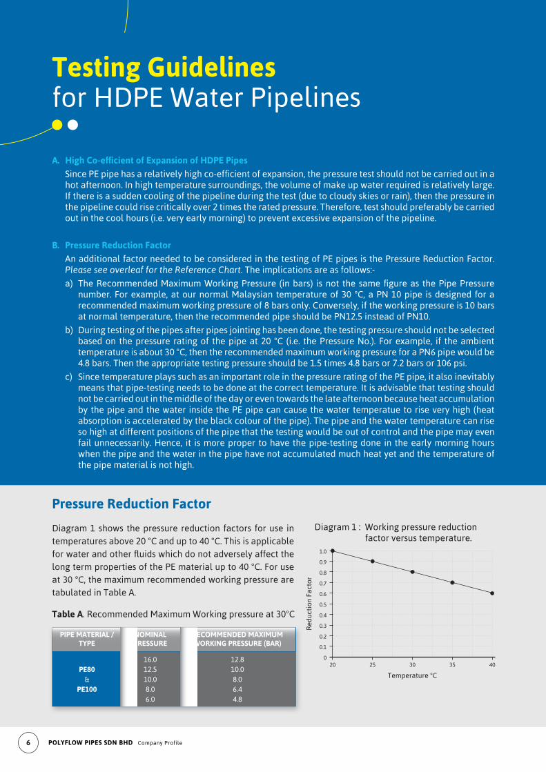
A. High Co-efficient of Expansion of HDPE Pipes
SincePEpipehasarelativelyhighco-efficientofexpansion,thepressuretestshouldnotbecarriedoutinahot afternoon. In high temperature surroundings, the volume of make up water required is relatively large. If there is a sudden cooling of the pipeline during the test (due to cloudy skies or rain), then the pressure in the pipeline could rise critically over 2 times the rated pressure. Therefore, test should preferably be carried out in the cool hours (i.e. very early morning) to prevent excessive expansion of the pipeline.
B. Pressure Reduction Factor
An additional factor needed to be considered in the testing of PE pipes is the Pressure Reduction Factor. Please see overleaf for the Reference Chart. The implications are as follows:-
a) TheRecommendedMaximumWorkingPressure (inbars) isnot thesamefigureas thePipePressurenumber. For example, at our normal Malaysian temperature of 30 °C, a PN 10 pipe is designed for a recommended maximum working pressure of 8 bars only. Conversely, if the working pressure is 10 bars at normal temperature, then the recommended pipe should be PN12.5 instead of PN10.
b) During testing of the pipes after pipes jointing has been done, the testing pressure should not be selected based on the pressure rating of the pipe at 20 °C (i.e. the Pressure No.). For example, if the ambient temperature is about 30 °C, then the recommended maximum working pressure for a PN6 pipe would be 4.8 bars. Then the appropriate testing pressure should be 1.5 times 4.8 bars or 7.2 bars or 106 psi.
c) Since temperature plays such as an important role in the pressure rating of the PE pipe, it also inevitably means that pipe-testing needs to be done at the correct temperature. It is advisable that testing should not be carried out in the middle of the day or even towards the late afternoon because heat accumulation by the pipe and the water inside the PE pipe can cause the water temperatue to rise very high (heat absorption is accelerated by the black colour of the pipe). The pipe and the water temperature can rise so high at different positions of the pipe that the testing would be out of control and the pipe may even fail unnecessarily. Hence, it is more proper to have the pipe-testing done in the early morning hours when the pipe and the water in the pipe have not accumulated much heat yet and the temperature of the pipe material is not high.
Testing Guidelinesfor HDPE Water Pipelines
Diagram 1 shows the pressure reduction factors for use in temperatures above 20 °C and up to 40 °C. This is applicable forwaterandotherfluidswhichdonotadverselyaffectthelong term properties of the PE material up to 40 °C. For use at 30 °C, the maximum recommended working pressure are tabulated in Table A.
Pressure Reduction Factor
0
0.1
0.2
0.3
0.4
0.5
0.6
0.7
0.8
0.9
1.0
20 25 30 35 40
Red
ucti
on F
acto
r
Temperature °C
Diagram 1 : Working pressure reduction factor versus temperature.
Table A. Recommended Maximum Working pressure at 30°C
PIPE MATERIAL / NOMINAL RECOMMENDED MAXIMUM TYPE PRESSURE WORKING PRESSURE (BAR)
16.0 12.8 PE80 12.5 10.0 & 10.0 8.0 PE100 8.0 6.4 6.0 4.8
7
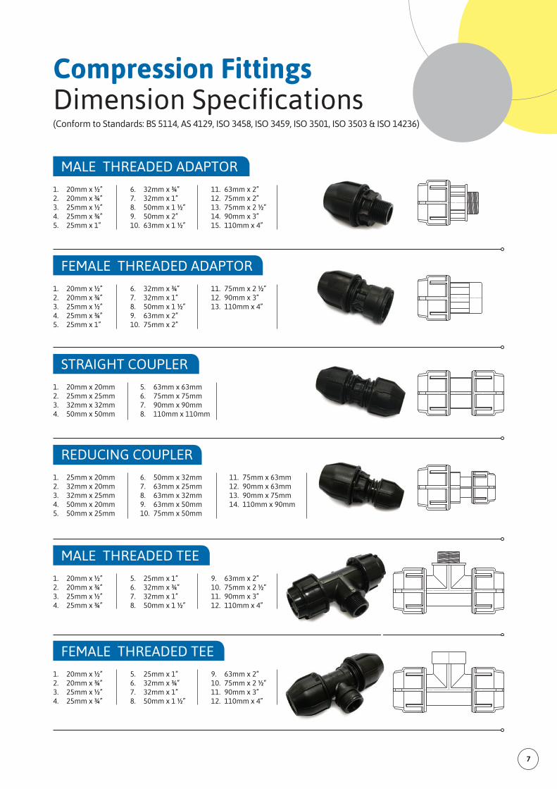
Compression Fittings DimensionSpecifications(Conform to Standards: BS 5114, AS 4129, ISO 3458, ISO 3459, ISO 3501, ISO 3503 & ISO 14236)
MALE THREADED ADAPTOR
1. 20mm x ½” 2. 20mm x ¾” 3. 25mm x ½” 4. 25mm x ¾” 5. 25mm x 1”
6. 32mm x ¾” 7. 32mm x 1” 8. 50mm x 1 ½” 9. 50mm x 2” 10. 63mm x 1 ½”
11. 63mm x 2” 12. 75mm x 2” 13. 75mm x 2 ½” 14. 90mm x 3” 15. 110mm x 4”
FEMALE THREADED ADAPTOR
1. 20mm x ½” 2. 20mm x ¾” 3. 25mm x ½” 4. 25mm x ¾” 5. 25mm x 1”
6. 32mm x ¾” 7. 32mm x 1” 8. 50mm x 1 ½” 9. 63mm x 2” 10. 75mm x 2”
11. 75mm x 2 ½” 12. 90mm x 3” 13. 110mm x 4”
STRAIGHT COUPLER
1. 20mm x 20mm 2. 25mm x 25mm 3. 32mm x 32mm 4. 50mm x 50mm
5. 63mm x 63mm 6. 75mm x 75mm 7. 90mm x 90mm 8. 110mm x 110mm
REDUCING COUPLER
1. 25mm x 20mm 2. 32mm x 20mm 3. 32mm x 25mm 4. 50mm x 20mm 5. 50mm x 25mm
6. 50mm x 32mm 7. 63mm x 25mm 8. 63mm x 32mm 9. 63mm x 50mm 10. 75mm x 50mm
11. 75mm x 63mm 12. 90mm x 63mm 13. 90mm x 75mm 14. 110mm x 90mm
MALE THREADED TEE
1. 20mm x ½” 2. 20mm x ¾” 3. 25mm x ½” 4. 25mm x ¾”
5. 25mm x 1” 6. 32mm x ¾” 7. 32mm x 1” 8. 50mm x 1 ½”
9. 63mm x 2” 10. 75mm x 2 ½” 11. 90mm x 3” 12. 110mm x 4”
FEMALE THREADED TEE
1. 20mm x ½” 2. 20mm x ¾” 3. 25mm x ½” 4. 25mm x ¾”
5. 25mm x 1” 6. 32mm x ¾” 7. 32mm x 1” 8. 50mm x 1 ½”
9. 63mm x 2” 10. 75mm x 2 ½” 11. 90mm x 3” 12. 110mm x 4”
8 POLYFLOW PIPES SDN BHD Company Profile
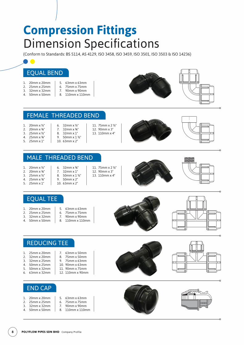
Compression Fittings DimensionSpecifications(Conform to Standards: BS 5114, AS 4129, ISO 3458, ISO 3459, ISO 3501, ISO 3503 & ISO 14236)
EQUAL BEND
1. 20mm x 20mm 2. 25mm x 25mm 3. 32mm x 32mm 4. 50mm x 50mm
5. 63mm x 63mm 6. 75mm x 75mm 7. 90mm x 90mm 8. 110mm x 110mm
FEMALE THREADED BEND
1. 20mm x ½" 2. 20mm x ¾" 3. 25mm x ½" 4. 25mm x ¾" 5. 25mm x 1"
6. 32mm x ½" 7. 32mm x ¾" 8. 32mm x 1" 9. 50mm x 1 ½" 10. 63mm x 2"
11. 75mm x 2 ½" 12. 90mm x 3" 13. 110mm x 4"
1. 20mm x ½" 2. 20mm x ¾" 3. 25mm x ½" 4. 25mm x ¾" 5. 25mm x 1"
6. 32mm x ¾" 7. 32mm x 1" 8. 50mm x 1 ½" 9. 50mm x 2" 10. 63mm x 2"
11. 75mm x 2 ½" 12. 90mm x 3" 13. 110mm x 4"
MALE THREADED BEND
EQUAL TEE
1. 20mm x 20mm 2. 25mm x 25mm 3. 32mm x 32mm 4. 50mm x 50mm
5. 63mm x 63mm 6. 75mm x 75mm 7. 90mm x 90mm 8. 110mm x 110mm
REDUCING TEE
1. 25mm x 20mm 2. 32mm x 20mm 3. 32mm x 25mm 4. 50mm x 25mm5. 50mm x 32mm 6. 63mm x 32mm
7. 63mm x 50mm 8. 75mm x 50mm9. 75mm x 63mm 10. 90mm x 63mm 11. 90mm x 75mm 12. 110mm x 90mm
END CAP
1. 20mm x 20mm 2. 25mm x 25mm 3. 32mm x 32mm 4. 50mm x 50mm
5. 63mm x 63mm 6. 75mm x 75mm 7. 90mm x 90mm 8. 110mm x 110mm
9
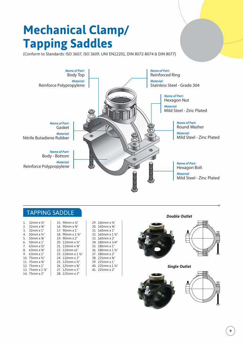
TAPPING SADDLE
1. 32mm x ½" 2. 32mm x ¾" 3. 32mm x 1" 4. 50mm x ½" 5. 50mm x ¾" 6. 50mm x 1" 7. 63mm x ½" 8. 63mm x ¾" 9. 63mm x 1" 10. 75mm x ½" 11. 75mm x ¾" 12. 75mm x 1" 13. 75mm x 1 ½" 14. 75mm x 2"
15. 90mm x ½" 16. 90mm x ¾" 17. 90mm x 1" 18. 90mm x 1 ½" 19. 90mm x 2" 20. 110mm x ½" 21. 110mm x ¾" 22. 110mm x1" 23. 110mm x 1 ½" 24. 110mm x 2" 25. 125mm x ½" 26. 125mm x ¾" 27. 125mm x 1" 28. 125mm x 2"
29. 160mm x ½" 30. 160mm x ¾" 31. 160mm x 1" 32. 160mm x 1 ½" 33. 160mm x 2" 34. 180mm x 3/4" 35. 180mm x 1" 36. 180mm x 1 ½" 37. 180mm x 2" 38. 225mm x ¾" 39. 225mm x 1" 40. 225mm x 1 ½" 41. 225mm x 2"
Mechanical Clamp/Tapping Saddles(Conform to Standards: ISO 3607, ISO 3609, UNI EN12201, DIN 8072-8074 & DIN 8077)
Name of Part:Reinforced RingMaterial:Stainless Steel - Grade 304
Name of Part:Hexagon Nut Material:Mild Steel - Zinc Plated
Name of Part:Hexagon Bolt Material:Mild Steel - Zinc Plated
Name of Part:Body Top
Material:Reinforce Polypropylene
Name of Part:GasketMaterial:
Nitrile Butadiene Rubber
Name of Part:Body - Bottom
Material:Reinforce Polypropylene
Name of Part:Round WasherMaterial:Mild Steel - Zinc Plated
Double Outlet
Single Outlet
10 POLYFLOW PIPES SDN BHD Company Profile
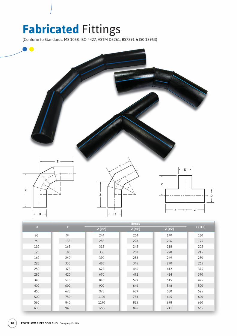
Fabricated Fittings(Conform to Standards: MS 1058, ISO 4427, ASTM D3261, BS7291 & IS0 13953)
Z
Z
D
r
Z
Z
D
r
D
D
Z
Z Z
Bends
D
r Z (90o) Z (60o) Z (45o)
Z (TEE)
63 94 244 204 190 180
90 135 285 228 206 195
110 165 315 245 218 205
125 188 338 258 228 215
160 240 390 288 249 230
225 338 488 345 290 265
250 375 625 466 412 375
280 420 670 492 424 390
345 518 818 599 515 475
400 600 900 646 548 500
450 675 975 689 580 525
500 750 1100 783 665 600
560 840 1190 835 698 630
630 945 1295 896 741 665
11
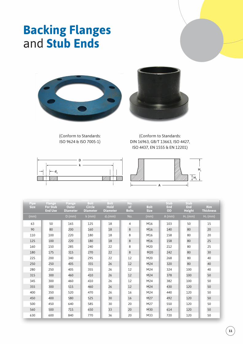
Backing Flanges and Stub Ends
(Conform to Standards:ISO 9624 & ISO 7005-1)
(Conform to Standards:DIN 16963, GB/T 13663, ISO 4427,
ISO 4437, EN 1555 & EN 12201)
Pipe Flange Flange Bolt Bolt No. Stub Stub Size For Stub Outer Circle Hold of Bolt End End Rim End Use Diameter Diameter Diameter Bolts Size OD Height Thickness
(mm) D (mm) k (mm) d2 (mm) No. (mm) A (mm) H1 (mm) H2 (mm)
63 50 165 125 18 4 M16 103 50 15
90 80 200 160 18 8 M16 140 80 20
110 100 220 180 18 8 M16 158 80 20
125 100 220 180 18 8 M16 158 80 25
160 150 285 240 22 8 M20 212 80 25
180 175 315 270 22 8 M20 242 80 30
225 200 340 295 22 12 M20 268 80 40
250 250 405 355 26 12 M24 320 80 40
280 250 405 355 26 12 M24 324 100 40
315 300 460 410 26 12 M24 378 100 50
345 300 460 410 26 12 M24 382 100 50
355 300 515 460 26 12 M24 430 120 50
400 350 520 470 26 16 M24 440 120 50
450 400 580 525 30 16 M27 492 120 50
500 450 640 585 30 20 M27 550 120 50
560 500 715 650 33 20 M30 614 120 50
630 600 840 770 36 20 M33 720 120 50
Dk
d2
A
H1
H2
12 POLYFLOW PIPES SDN BHD Company Profile
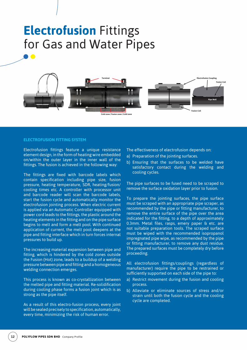
Cold zone | Fusion zone | Cold zone
Terminal Electrofusion Coupling
Fusion Coil
Fusion Coil
Pipe Wall
Electrofusion Fittingsfor Gas and Water Pipes
ELECTROFUSION FITTING SYSTEM
Electrofusion fittings feature a unique resistanceelement design, in the form of heating wire embedded on/within the outer layer in the inner wall of the fittings.Thefusionisachievedinthefollowingway:
The fittings are fixed with barcode labels whichcontain specification including pipe size, fusionpressure, heating temperature, SDR, heating/fusion/cooling times etc. A controller with processor unit and barcode reader will scan the barcode labels, start the fusion cycle and automatically monitor the electrofusion jointing process. When electric current is applied via an Automatic Controller equipped with powercordleadstothefittings,theplasticaroundtheheatingelementsinthefittingandonthepipesurfacebegins to melt and form a melt pool. With continued application of current, the melt pool deepens at the pipeandfittinginterfacewhichinturnforcesinternalpressures to build up.
The increasing material expansion between pipe and fitting,which is hindered by the cold zones outsidethe Fusion (Hot) zone, leads to a buildup of a welding pressurebetweenpipeandfittingandahomogeneouswelding connection emerges.
This process is known as co-crystallization between themeltedpipeandfittingmaterial.Re-solidificationduring cooling phase forms a fusion joint which is as strong as the pipe itself.
As a result of this electro-fusion process, every joint willbesealedpreciselytospecification,automatically,every time, minimizing the risk of human error.
The effectiveness of electrofusion depends on:
a) Preparation of the jointing surfaces.
b) Ensuring that the surfaces to be welded have satisfactory contact during the welding and cooling cycles.
The pipe surfaces to be fused need to be scraped to remove the surface oxidation layer prior to fusion.
To prepare the jointing surfaces, the pipe surface must be scraped with an appropriate pipe scraper, as recommendedbythepipeorfittingmanufacturer,toremove the entire surface of the pipe over the area indicatedforthefitting,toadepthofapproximately0.3mm. Metal files, rasps, emery paper & etc. arenot suitable preparation tools. The scraped surface must be wiped with the recommended isopropanol impregnated pipe wipe, as recommended by the pipe orfittingmanufacturer, to removeanydust residue.The prepared surfaces must be completely dry before proceeding.
All electrofusion fittings/couplings (regardless ofmanufacturer) require the pipe to be restrained or sufficientlysupportedoneachsideofthepipeto:
a) Restrict movement during the fusion and cooling process.
b) Alleviate or eliminate sources of stress and/or strain until both the fusion cycle and the cooling cycle are completed.
13
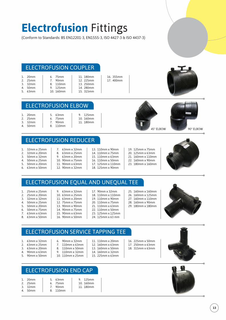
Electrofusion Fittings(Conform to Standards: BS EN12201-3, EN1555-3, ISO 4427-3 & ISO 4437-3)
ELECTROFUSION ELBOW
1. 20mm 2. 25mm 3. 32mm 4. 50mm
5. 63mm 6. 75mm 7. 90mm 8. 110mm
9. 125mm 10. 160mm 11. 180mm
ELECTROFUSION EQUAL AND UNEQUAL TEE
1. 25mm x 25mm 2. 25mm x 20mm 3. 32mm x 32mm 4. 50mm x 25mm 5. 50mm x 20mm 6. 50mm x 75mm 7. 63mm x 63mm 8. 63mm x 50mm
9. 63mm x 32mm 10. 63mm x 25mm 11. 63mm x 20mm 12. 75mm x 75mm 13. 90mm x 90mm 14. 90mm x 75mm 15. 90mm x 63mm 16. 90mm x 50mm
17. 90mm x 32mm 18. 110mm x 110mm 19. 110mm x 90mm 20. 110mm x 75mm 21. 110mm x 63mm 22. 110mm x 50mm 23. 125mm x 125mm 24. 125mm x 63 mm
25. 160mm x 160mm 26. 160mm x 125mm 27. 160mm x 110mm 28. 160mm x 90mm 29. 180mm x 180mm
ELECTROFUSION SERVICE TAPPING TEE
1. 63mm x 32mm 2. 63mm x 25mm 3. 63mm x 20mm 4. 90mm x 63mm 5. 90mm x 50mm
6. 90mm x 32mm 7. 110mm x 63mm 8. 110mm x 50mm 9. 110mm x 32mm 10. 110mm x 25mm
11. 110mm x 20mm 12. 160mm x 63mm 13. 160mm x 50mm 14. 160mm x 32mm 15. 225mm x 63mm
16. 225mm x 50mm 17. 250mm x 63mm 18. 315mm x 63mm
ELECTROFUSION END CAP
1. 20mm 2. 25mm 3. 32mm 4. 50mm
5. 63mm 6. 75mm 7. 90mm 8. 110mm
9. 125mm 10. 160mm 11. 180mm
ELECTROFUSION COUPLER
1. 20mm 2. 25mm 3. 32mm 4. 50mm 5. 63mm
6. 75mm 7. 90mm 8. 110mm 9. 125mm 10. 160mm
11. 180mm 12. 225mm 13. 250mm 14. 280mm 15. 315mm
16. 355mm 17. 400mm
ELECTROFUSION REDUCER
1. 32mm x 25mm 2. 32mm x 20mm 3. 50mm x 32mm 4. 50mm x 25mm 5. 50mm x 20mm 6. 63mm x 50mm
7. 63mm x 32mm 8. 63mm x 25mm 9. 63mm x 20mm 10. 90mm x 75mm 11. 90mm x 63mm 12. 90mm x 32mm
13. 110mm x 90mm 14. 110mm x 75mm 15. 110mm x 63mm 16. 110mm x 50mm17. 125mm x 110mm 18. 125mm x 90mm
19. 125mm x 75mm 20. 125mm x 63mm 21. 160mm x 110mm 22. 160mm x 90mm 23. 180mm x 160mm
45° ELBOW 90° ELBOW
14 POLYFLOW PIPES SDN BHD Company Profile