Embed Size (px)
Citation preview


Your Solution Your Excavation, Your Solution
Depth 2 metres Is there any groundwater present within the depth of the excavation?
No
Size 2.5 x 2.5 Are there any large surcharges within the zone of influence?
No
Are there any problematic ground conditions present?
No Is there any Sloping ground ? No
Which soil type is predominately present in the ground?
Granular Are there any water courses present
No
Selected Solution
Solution name Granular, Walers, 2 Frame, 2.0m Deep
Maximum Allowable Depth 2.0m Deep
Length Range 2- 5m Deep
Width Range 0.55m- 4.30m Deep
Clearance 0.9m
Weight Varies

Contents
Description Page CDM 2015 statement 4 Specification of Support Equipment 5 Basis of design 6-7 General Notes 8-9 Residual Risk Schedule 10-11 Design Calculations 12 Summary 13-14 Drawing 15-16 Installation Guide 17-18 Installations and Removal Sequence 19-20 Internal Design Certificate 21
IMPORTANT PLEASE NOTE 1. The design calculations contained in this document have been prepared using
Groundforce Shorco’s specialist temporary works design software. The designs have been based on the generic assumptions listed, which the competent person must assess as having been satisfied. If any parameter exceeds these assumptions, then the user should obtain a site specific design by contacting Groundforce on 0800 000 345.
2. It is the contractor’s responsibility to communicate the information contained within this design to all relevant parties including the site principal designer(s) and temporary works coordinators where appropriate. It is also the contractor’s responsibility to ensure that this information is incorporated into site specific method statements and risk assessments.
3. Any significant residual risks remaining after the design process will be documented both on the relevant page of this design and also on the drawings. It is the contractor’s responsibility to take steps to reduce these risks to an acceptable level.
Please ensure that this document is passed on to the site temporary works co-ordinator and or main contractor prior to commencing any excavation work. If in doubt ASK

CDM 2015 Statement
The key aim of the CDM 2015 regulations is to integrate health and safety into the management of the project. As a result, specific duties are imposed on the key parties involved in a construction project namely:
1. The client
2. The principal designer (on sites where there is, or is likely to be, more than one contractor at any time)
3. Designers (this includes Groundforce Shorco as appointed temporary works designers of the original solution
and the person selecting the standard solution).
4. The principal contractor (on sites where there is, or is likely to be, more than one contractor at any time)
5. Contractors
As competent temporary works’ designers operating within the CDM regulations, specifically regulation 9 and 10, along with regulation 8 – general duties, Groundforce Shorco undertake to:
1. Adopt a safety first approach to design work in accordance with recognised standards and codes of practice.
2. Eliminate hazards and reduce risks in their design process.
3. Communicate clear and concise information about design assumptions and residual risks to all relevant parties.
Under CDM, the designer is defined as anyone preparing or modifying a design. A design can consist of drawings, details or specifications relating to a structure. As such, a designer includes anyone who specifies a particular method of work, equipment or material. This person will assume the role and responsibilities of a designer under the CDM Regulations and must have the skills, knowledge and experience, necessary to fulfil the role. As a designer, they are duty bound to cooperate with other persons working on a project to enable them to fulfil their duties and maintain the health and safety of themselves and others. Based on the above definitions, it is clear that great care should be taken when specifying shoring equipment, and should only be done by those with a sufficient level of competence to fulfil the role of the designer.
It is the responsibility of the person selecting the standard solution to check that the site conditions match those assumed in the solution. In addition, as this person is effectively specifying the solution, they assume the role and responsibilities of the designer under CDM.
One responsibility imposed on the client under CDM is to ensure that a principal designer has been appointed on sites where there is, or is likely to be, more than one contractor at any time.
We have not been informed who the principal designer for this site is. A copy of this design should be passed on to the principal designer for consideration.
In addition to the requirements of the CDM 2015 regulations, the main contractor or principle contractor should appoint temporary works’ coordinator (TWC) and supervisor(s) (TWS) as recommended in BS 5975:2019. The duties of the TWC(s)’ and TWS(s)’ are specified in section 11 & 12 of the above standard.
A copy of this design should be passed on to the TWC and or the TWS for consideration.

Specification of Equipment
Sheets Sheet Type Groundforce SD33 or KD4 (lapped sheets) Minimum Length 2.50m plus required upstand (to be assessed by contractor) Allowable Bending Movement
SD33 Trench Sheets 8.5kNm/m KD4 Trench Sheets 19.0kNm/m
Calculated Max. B Moment: 5.4kNm/m (at stage 3) Calculated Max. Deflection: Less Than 20mm
Waler Frames 2 No. levels of Groundforce Aluminium or Steel Walers-
Refer to Drawing
Working Loads
2.0m Aluminium Waler 63.7kN/m
3.0m Aluminium Waler 23.6kN/m
5.0m Aluminium Waler 29.7kN/m
3.9m HD Steel Waler 40.4kN/m
5.0m HD Steel Waler 28.0kN/m
5.0m SHD Steel Waler 40.0kN/m
Type AA 63.7kN/m
Type AB 63.7kN/m
Type BA 63.7kN/m
Type BB 59.2kN/m
Type CA 40.6kN/m
Type AB 27.4kN/m
Calculated Maximum load 8.2kN/m (Frame 2 at stage 3) Calculated Deflected load Less than 50mm
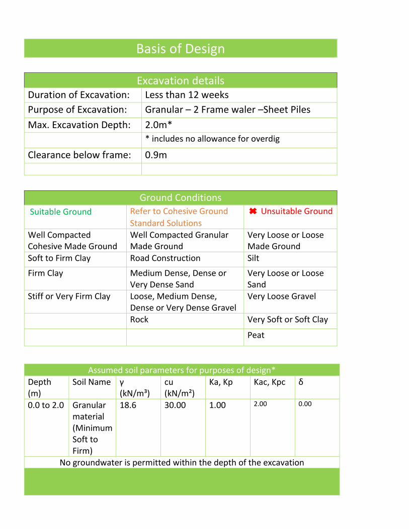
Basis of Design
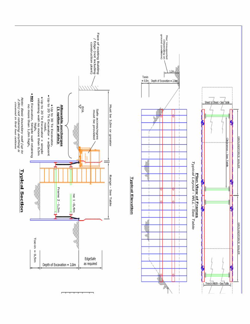
Excavation details Duration of Excavation: Less than 12 weeks Purpose of Excavation: Granular – 2 Frame waler –Sheet Piles Max. Excavation Depth: 2.0m* * includes no allowance for overdig
Clearance below frame: 0.9m
Ground Conditions Suitable Ground Refer to Cohesive Ground
Standard Solutions Unsuitable Ground
Well Compacted Cohesive Made Ground
Well Compacted Granular Made Ground
Very Loose or Loose Made Ground
Soft to Firm Clay Road Construction Silt
Firm Clay Medium Dense, Dense or Very Dense Sand
Very Loose or Loose Sand
Stiff or Very Firm Clay Loose, Medium Dense, Dense or Very Dense Gravel
Very Loose Gravel
Rock Very Soft or Soft Clay
Peat
Assumed soil parameters for purposes of design* Depth (m)
Soil Name γ (kN/m³)
cu (kN/m²)
Ka, Kp Kac, Kpc δ
0.0 to 2.0 Granular material (Minimum Soft to Firm)
18.6 30.00 1.00 2.00 0.00
No groundwater is permitted within the depth of the excavation

Basis of design (continued)
Surcharges (one option per side) A uniform surcharge of 16kN/m² at ground level to allow for general site traffic
Permitted Not permitted Excavators up to 30 tonne weight working near the excavation.
Plant exceeding 30 tonne (including cranes)
Live roads up to and including Principal (A) roads, site access or closed roads
Railways, motorways and trunk roads
Simple boundary wall no more than 1.0m high)
Embankments, sloping ground (greater than 1 in 10, stored material.
Buildings/structures
Unsuitable site conditions Design is not valid if any of the following conditions exist on site:
• Adjacent watercourses • Presence of groundwater • Excavation duration exceeding 12 weeks
General Notes
1. This design is only valid when used in conjunction with Groundforce Shorco & Piletec equipment.
2. This design is only valid for short-term (< 12 wks) temporary works’ applications. Therefore total stress soil parameters have been used for cohesive materials in the temporary case.
3. The installation and use of the equipment is the responsibility of the Hirer. It is essential that appropriately trained personnel are employed to install and use this equipment in accordance with the design specifications and user guides and general good practice. Groundforce can provide an installation advisory service to assist you with installing the equipment. Alternatively we can provide on site 'toolbox training'. Detailed user guides have been provided with the equipment, if not please ask.
4. The contractor is responsible for:
• Providing adequate lifting facilities to ensure the safe off-loading, installation and removal of the equipment. Equipment weights are listed on the scheme drawings and user guides.
• Checking for the presence of underground and overhead services and dealing with accordingly.
• Providing appropriate edge protection to the perimeter of the excavation and also suitable means of access / egress to and from the excavation.
5. Unless otherwise stated in the scheme specific notes, all structural information has been calculated as the “worst case” loading resulting from a stage-by-stage installation sequence analysis.
6. The temporary works scheme has been designed with reference to the following documents as considered appropriate for the specific design:
• British Steel (Arcelor) Piling Handbook; • CIRIA Special Publication 95 (1993): The Design & Construction of Sheet-Piled
Cofferdams. • CIRIA Report C760: Embedded Retaining Walls (replaces CIRIA C580) • BS 8002:2015 Code of Practice for Earth Retaining Structures • BS 6031:2009 Code of Practice for Earthworks
7. The structural resistance of the supporting equipment has been generally designed in accordance with the following standards as considered appropriate to the specific design:
• BS 5950 Part1-2000: Structural Use of Steelwork in Building where applicable. • Eurocode 3: Design of steel structures. BS EN 1993 (part 1). • Eurocode 9: Design of aluminium structures. BS EN 1999 (part 1). • BS EN 14653 (parts 1 & 2) 2005: Manually operated hydraulic shoring systems for
groundwork support.
8. Attention is drawn to current safety legislation particularly CDM 2015 regulations & BS 5975:2019 (see also page 2). Appropriate site specific risk assessments must be performed by the contractor. In addition, the excavation must be inspected by a competent person in accordance with statutory requirements. Any defects or signs of deterioration to the support system must be notified to us immediately and work stopped within the excavation.
9. Any installation method statement supplied by GFS will be non-site specific. This will not take into account health and safety matters which should be dealt with in the hirer’s own safety method statement. In addition the method statement should be read in conjunction with the design brief, drawings and equipment installation instructions supplied by Groundforce. Any deviation from these instructions/recommendations should be notified to us for verification of the adequacy of the scheme.

Residual Risk Schedule
The followings items have been identified as potential residual risks remaining after the design process risk assessment. Based on the information that we have available, we have allocated each risk a rating number depending on its potential to cause a problem. Those with a rating of 2, 3 and 4 are highlighted on the scheme drawing. A further site specific risk assessment must be carried out on these items to assess their importance and potential consequence and to determine a course of action or monitoring in order to mitigate the risk to an acceptable level.
Notes on possible further mitigation action required at site level.
1. Site specific risk assessments: Site specific risk assessments must be performed by the contractor. In addition the excavation must be inspected by a competent person in accordance with statutory requirements. Any defects or signs of deterioration to the support system must be notified to Groundforce immediately and work stopped within the excavation.
2. Size and weight of the equipment: Ensure that this information is taken into account during the planning of any work to be carried out, including the provision of adequate lifting facilities to ensure the safe loading, installation and removal of the equipment.
3. Ground conditions: Should the ground conditions differ from those considered, excavation should stop immediately and a site specific temporary works design be obtained. Any immediate hazards should be made safe by backfilling if necessary.
4. Surcharge: A uniform surcharge of 16kN/m2 has been applied at ground level to allow for any of the following surcharges (1 option per side):
Residual Risk Item Risk Rating
Site specific risk assessments 2 Size and weight of the equipment 2 Ground conditions 2 Surcharge 2 Accidental excavation (Overdig) 2 Working at height & access/egress 2 Ground movement 2 Sheet damage 2 Unsupported ground at ends of excavation 2 Dig & lower solution 2
Key to risk rating 1 Unlikely to be a problem 2 Possible Problem 3 Probable Problem 4 Almost certain to be a problem

• Excavators up to 30 tonne weight working near the excavation. • Live roads up to and including Principal (A) roads, site access or closed roads OR • Simple boundary wall no more than 1.0m high. If plant exceeds weight limit of 30Te, or
total surcharge loading is exceeded design stated values scheme needs to be reassessed. All spoil and excavated material should be moved to outside the zone of influence to avoid additional surcharging of the excavation.
5. Accidental excavation (Overdig): In the interests of design economy, overdig has not been allowed for in the design calculations. Specific control measures should be put in place to ensure that the dig is not allowed to progress beyond the indicated formation level.
6. Working at height & access/egress: Suitable edge protection and appropriate means of access and egress to and around the excavation. Groundforce's integrated EdgeSafe and LadderSafe products are recommended.
7. Ground movement: Monitor the ground surrounding the excavation for signs of movement (cracks, settlement etc.) and seek advice if necessary. Risk assess the impact of any ground movement on the integrity of any adjacent structures, roads and services.
8. Sheet damage: Due to the use of lightweight sheets in potentially hard ground there is a chance of sheet damage. Installation should be carefully monitored to ensure damage of sheets is minimised. Pre Auger may be required.
9. Unsupported ground at ends of excavation: The ends of the excavation should be battered back at a safe angle or suitable waler end bearers and trench sheets used. Trench sheets should not be placed against the hydraulic cylinders.
10. Dig and lower: Both frames must be introduced into the excavation immediately, nominally pressurised, and lowered into position as excavation proceeds. The dig depth must not exceed 300mm below the lower frame until it is installed and fully pressurised in its final location. It is recommended that personnel do not enter the excavation during the lowering of the frames and/or digging operation until the frames are installed in their final locations.


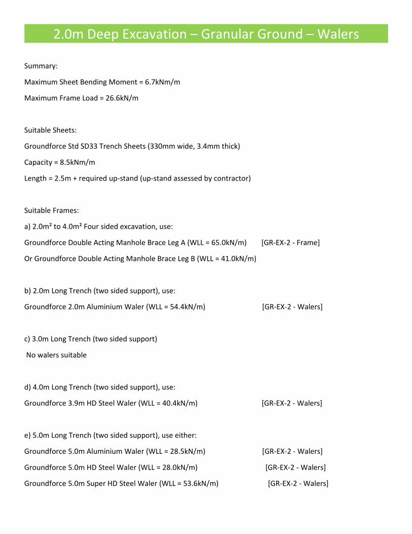
2.0m Deep Excavation – Granular Ground – Walers
Summary:
Maximum Sheet Bending Moment = 6.7kNm/m
Maximum Frame Load = 26.6kN/m
Suitable Sheets:
Groundforce Std SD33 Trench Sheets (330mm wide, 3.4mm thick)
Capacity = 8.5kNm/m
Length = 2.5m + required up-stand (up-stand assessed by contractor)
Suitable Frames:
a) 2.0m² to 4.0m² Four sided excavation, use:
Groundforce Double Acting Manhole Brace Leg A (WLL = 65.0kN/m) [GR-EX-2 - Frame]
Or Groundforce Double Acting Manhole Brace Leg B (WLL = 41.0kN/m)
b) 2.0m Long Trench (two sided support), use:
Groundforce 2.0m Aluminium Waler (WLL = 54.4kN/m) [GR-EX-2 - Walers]
c) 3.0m Long Trench (two sided support)
No walers suitable
d) 4.0m Long Trench (two sided support), use:
Groundforce 3.9m HD Steel Waler (WLL = 40.4kN/m) [GR-EX-2 - Walers]
e) 5.0m Long Trench (two sided support), use either:
Groundforce 5.0m Aluminium Waler (WLL = 28.5kN/m) [GR-EX-2 - Walers]
Groundforce 5.0m HD Steel Waler (WLL = 28.0kN/m) [GR-EX-2 - Walers]
Groundforce 5.0m Super HD Steel Waler (WLL = 53.6kN/m) [GR-EX-2 - Walers]


Installation and removal sequence

Installation and Removal Sequence (continued)