Embed Size (px)
Citation preview

1
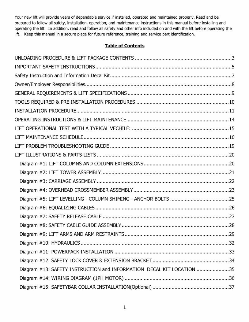
Your new lift will provide years of dependable service if installed, operated and maintained properly. Read and be
prepared to follow all safety, installation, operation, and maintenance instructions in this manual before installing and
operating the lift. In addition, read and follow all safety and other info included on and with the lift before operating the
lift. Keep this manual in a secure place for future reference, training and service part identification.
Table of Contents
UNLOADING PROCEDURE & LIFT PACKAGE CONTENTS .................................................................. 3
IMPORTANT SAFETY INSTRUCTIONS ............................................................................................. 5
Safety Instruction and Information Decal Kit ................................................................................... 7
Owner/Employer Responsibilities.................................................................................................... 8
GENERAL REQUIREMENTS & LIFT SPECIFICATIONS ....................................................................... 9
TOOLS REQUIRED & PRE INSTALLATION PROCEDURES ............................................................... 10
INSTALLATION PROCEDURE ........................................................................................................ 11
OPERATING INSTRUCTIONS & LIFT MAINTENANCE ..................................................................... 14
LIFT OPERATIONAL TEST WITH A TYPICAL VECHILE: .................................................................. 15
LIFT MAINTENANCE SCHEDULE ................................................................................................... 16
LIFT PROBLEM TROUBLESHOOTING GUIDE ................................................................................. 19
LIFT ILLUSTRATIONS & PARTS LISTS .......................................................................................... 20
Diagram #1: LIFT COLUMNS AND COLUMN EXTENSIONS .......................................................... 20
Diagram #2: LIFT TOWER ASSEMBLY ....................................................................................... 21
Diagram #3: CARRIAGE ASSEMBLY .......................................................................................... 22
Diagram #4: OVERHEAD CROSSMEMBER ASSEMBLY ................................................................. 23
Diagram #5: LIFT LEVELLING - COLUMN SHIMING - ANCHOR BOLTS ........................................ 25
Diagram #6: EQUALIZING CABLES ........................................................................................... 26
Diagram #7: SAFETY RELEASE CABLE ...................................................................................... 27
Diagram #8: SAFETY CABLE GUIDE ASSEMBLY ......................................................................... 28
Diagram #9: LIFT ARMS AND ARM RESTRAINTS ....................................................................... 29
Diagram #10: HYDRAULICS ..................................................................................................... 32
Diagram #11: POWERPACK INSTALLATION .............................................................................. 33
Diagram #12: SAFETY LOCK COVER & EXTENSION BRACKET .................................................... 34
Diagram #13: SAFETY INSTRUCTION and INFORMATION DECAL KIT LOCATION ...................... 35
Diagram #14: WIRING DIAGRAM (1PH MOTOR) ....................................................................... 36
Diagram #15: SAFETYBAR COLLAR INSTALLATION(Optional) .................................................... 37
2
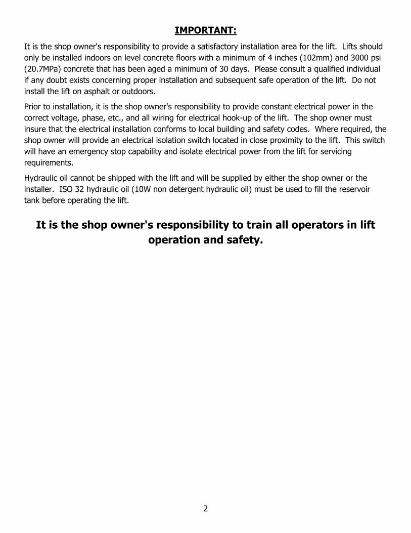
IMPORTANT:
It is the shop owner's responsibility to provide a satisfactory installation area for the lift. Lifts should
only be installed indoors on level concrete floors with a minimum of 4 inches (102mm) and 3000 psi
(20.7MPa) concrete that has been aged a minimum of 30 days. Please consult a qualified individual
if any doubt exists concerning proper installation and subsequent safe operation of the lift. Do not
install the lift on asphalt or outdoors.
Prior to installation, it is the shop owner's responsibility to provide constant electrical power in the
correct voltage, phase, etc., and all wiring for electrical hook-up of the lift. The shop owner must
insure that the electrical installation conforms to local building and safety codes. Where required, the
shop owner will provide an electrical isolation switch located in close proximity to the lift. This switch
will have an emergency stop capability and isolate electrical power from the lift for servicing
requirements.
Hydraulic oil cannot be shipped with the lift and will be supplied by either the shop owner or the
installer. ISO 32 hydraulic oil (10W non detergent hydraulic oil) must be used to fill the reservoir
tank before operating the lift.
It is the shop owner's responsibility to train all operators in lift
operation and safety.

3
UNLOADING PROCEDURE & LIFT PACKAGE CONTENTS
For your information:
All lift components are grouped together in one package held at each end by steel frames.
Unpacking Procedure:
When the lift arrives on site:
✓ If possible have lift unloaded in the installation area.
✓ Check for freight damage and report immediately to the shipping company.
✓ Check for missing parts and report immediately to the factory. 1-877-799-LIFT(5438) or
(905) 847-1198
Main Components include:
• Power Side Column and Carriage Assembly – 1 pc (c/w equalizing cable, 2 arm
restraint assembles and 1 hydraulic cylinder assembly)
• Opposite Side Column and Carriage Assembly – 1 pc (c/w equalizing cable and 2
arm restraint assembles and 1 hydraulic cylinder assembly)
• Column Extensions – 2 pc
• Overhead Crossmember – 3 pc (c/w 4 steel cable pulleys)
• Overhead Safety Shutoff Bar – 1 pc
• Arms – 4 pc (c/w arm restraint gear assemblies)
• Powerpack Assembly – 1 pc
Accessory and Hardware Box includes:
• Micro-switch for Overhead Safety Shutoff Bar - 1pc (c/w 2 mounting brackets and
hardware)
• Baseplate Shims (6mm - 3mm - 1mm assortment) - Anchor Bolt Assemblies - 10 pc
• Arm Pins – 4 pc (c/w roll pins to secure them)
• Adjustable Rubber Lifting Pad Assembly – 4 pcs
• Stack Pad Adapter (3”) – 4 pcs (only with “V and P” series lifts)
• Stack Pad Adapter (6”) – 4 pcs (only with “V and P” series lifts)
• Truck Adapter – 4 pcs
• Rubber Door Guards – 2 pcs (only with “P” series lifts – not with ”V” series)
• Outer Arm (Honda) Adapter – 2 pcs (only with “P” series lifts – not with “V” series)
• Hydraulic Hose – 2 long and 1 short (also 1 hydraulic "T" fitting and powerpack
adapter fitting)
• Rubber Mounts for Powerpack - 4 pcs
• Safety Lock Release Cable – 1 pc (c/w 2 pulley brackets and fittings)

4
• Safety Lock Cover – 2 pcs
• Fittings Box (bolts, washers, nuts, screws, cable ties, etc.)
• ALI - "Lifting It Right" Manual
• Automotive Lift Safety Tips Hang Card
• Automotive Lift, Operation, Inspection and Maintenance Manual
• Owner’s Manual
5
IMPORTANT SAFETY INSTRUCTIONS
When using your garage equipment, basic safety precautions should always be followed,
including the following:
1. Read all instructions
2. Care must be taken as burns can result from touching hot parts
3. Do not operate equipment with a damaged cord or if equipment has been dropped or
damaged – until it has been examined by a qualified service person
4. Do not let a cord hang over the edge of the table, bench, or counter or come in contact
with hot manifolds or moving fan blades
5. Let equipment cool completely before putting away. Loop cord loosely around equipment
when storing
6. To reduce risk of fire, do not operate equipment in the vicinity of open containers of
flammable liquids (gasoline)
7. Adequate ventilation should be provided when working on operating internal combustion
engines
8. Keep hair, loose clothing, fingers, and all parts of body away from moving parts
9. To reduce the risk of electric shock, do not use on wet surfaces or expose to rain
10. Use only as directed in this manual. Use only manufacturer’s recommended attachments
11. ALWAYS WEAR SAFETY GLASSES. Everyday eyeglasses only have impact resistant
lenses, they are not safety glasses
Basic common-sense safety precautions should always be followed when installing, operating
and maintaining the lift as a risk of fire, electric shock, or injury may be present.
In addition:
1. Read and follow all safety instructions and decals included with the lift. Read and follow
all safety instructions in this manual. Read and follow the ALI "Lifting It Right" manual
(included with the lift). Always use the "Vehicle Lifting Points" reference guide when lifting
a vehicle. Insure all materials stay up to date(www.autolift.org/ )
2. Only trained and authorized personnel should position a vehicle and operate the lift. Do
not allow customers or bystanders to operate the lift or be in the lift area.
3. Inspect the lift daily. Do not operate if potential problems have been identified or lift
malfunctions. Do not operate if lift has damaged or broken components. Never walk or
work under the lift unless all safety locks are completely engaged.
4. Never overload the lift. The rated capacity decal is located on the powerpack column. The
hydraulic system on this lift is not designed to be a load holding devise. Mechanical safety
locks must be engaged before proceeding under the lift, with vehicle servicing, or system
maintenance. Never override operating controls. This is unsafe and will void the warranty.

6
5. Before driving a vehicle between the columns, position all arms to insure unobstructed
entry. Do not hit or run over arms as this could damage the lift and/or vehicle.
6. Use all 4 arms to raise a vehicle. Position all lift pads to contact vehicle manufacturer’s
recommended lifting points. Raise lift slowly until all pads contact the vehicle. Check all
pads for complete and secure contact with the vehicle. Check all arm restraints to insure
they are engaged properly. Check that vehicle is stable on the lift. Only after confirming
these procedures, raise the lift to desired working height.
7. Special care must be used when lifting pick-up trucks. Optional truck adapters may be
required to reach manufacturer recommended lifting points. Always use these lifting
points. Running boards and other installed accessories may also require optional
adapters. Insure contents of the cargo box will not affect vehicle balance while on the lift.
8. Important: Removal or installation of heavier parts can change the vehicle's center of
gravity on the lift resulting in a critical load shift. The vehicle may then be unstable. Plan
ahead for this possibility to insure continued safety and refer to the vehicle
manufacturer’s service manual for recommended procedures.
9. Always keep the lift area free of obstructions and debris. Clean up grease and oil spills
immediately.
10. Never raise a vehicle with passengers inside. Before lowering a vehicle, check the lift and
lift area and remove all obstructions. Before removing vehicle from the lift or lift area,
position arms to the drive through position and confirm an unobstructed exit.

7
Safety Instruction and Information Decal Kit
IMPORTANT: Review all safety information daily with all lift operators.
LIFT SAFETY and LIFT MAINTENANCE
MUST BE PART OF YOUR DAILY ROUTINE

8
OWNER/EMPLOYER’S RESPONSIBILITIES
The owner/employer:
• Shall ensure that lift operators are qualified and that they are trained in the safe
use and operation of the lift using the manufacturer’s operating instructions;
ALI/SM, “Lifting It Right” safety manual; ALI/ST, “Safety Tips” card; ANSI/ALI
ALOIM, Standard for Automotive Lifts – Safety Requirements for Operation,
Inspection and Maintenance; ALI/WL Series, ALI Uniform Warning Label
Decals/Placards; and in the case of frame engaging lifts, ALI/LP-Guide, “Quick
Reference Guide – Vehicle Lifting Points for Frame Engaging Lifts”.
• Shall establish procedures to periodically inspect the lift in accordance with the lift
manufacturer’s instructions or ANSI/ALI ALOIM, Standard for Automotive Lifts –
Safety Requirements for Operation, Inspection and Maintenance; and the employer
shall ensure that lift inspectors are qualified and that they are adequately trained in
the inspection of the lift.
• Shall establish procedures to periodically maintain the lift in accordance with the lift
manufacturer’s instructions or ANSI/ALI ALOIM, Standard for Automotive Lifts –
Safety Requirements for Operation, Inspection and Maintenance; and the employer
shall ensure that lift maintenance personnel are qualified and that they are
adequately trained in the maintenance of the lift.
• Shall maintain the periodic inspection and maintenance records recommended by
the manufacturer or ANSI/ALI ALOIM, Standard for Automotive Lifts – Safety
Requirements for Operation, Inspection and Maintenance.
• Shall display the lift manufacturer’s operating instructions; ALI/SM, “Lifting It
Right” safety manual; ALI/ST, “Safety Tips” card; ANSI/ALI ALOIM, Standard for
Automotive Lifts – Safety Requirements for Operation, Inspection and
Maintenance; ALI/WL Series, ALI Uniform Warning Label Decals/Placards; and in
the case of frame engaging lifts, ALI/LP-Guide, “Quick Reference Guide – Vehicle
Lifting Points for Frame Engaging Lifts”; in a conspicuous location in the lift area
convenient to the operator.
• Shall review and understand the proper requirements outlined in ANSI/ALI ALIS,
Safety Requirements for Installation and Service of Automotive Lifts.
• Shall consult with a qualified person to address seismic loads and other local or
state requirements.
9
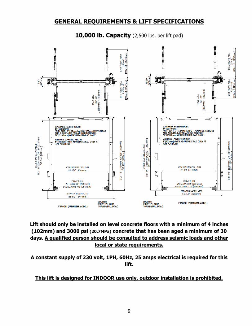
GENERAL REQUIREMENTS & LIFT SPECIFICATIONS
10,000 lb. Capacity (2,500 lbs. per lift pad)
Lift should only be installed on level concrete floors with a minimum of 4 inches
(102mm) and 3000 psi (20.7MPa) concrete that has been aged a minimum of 30
days. A qualified person should be consulted to address seismic loads and other
local or state requirements.
A constant supply of 230 volt, 1PH, 60Hz, 25 amps electrical is required for this
lift.
This lift is designed for INDOOR use only, outdoor installation is prohibited.

10
TOOLS REQUIRED & PRE INSTALLATION PROCEDURES
Tools Required
✓ 4” x 4” Wooden Blocks (for unpacking)
✓ 16ft. Measuring Tape
✓ Chalk Line and Chalk
✓ Side Cutters
✓ Crow Bar
✓ Metric & SAE Wrenches and Ratchet Set
✓ Metric & SAE Allen Key Sets
✓ Hammer & Screwdrivers
✓ 12 ft. Step Ladders - 2 (2 people using 12 ft. ladders should install the overhead crossmember
assembly)
✓ 4 ft. Levels - 2
✓ Rotary Hammer Drill with 3/4” diameter Masonry Drill Bit
Pre-Installation Procedures
Before proceeding with installation, read the installation manual and insure all instructions are
fully understood and all component parts are accounted for.
1. In the installation area, identify the center line of the bay and mark the floor. Also mark
the center of bay entrance door. Connect these two points with a chalk line in the area
where lift will be located. Draw a second chalk line at 90° to locate the positions of both
lift columns (refer to lift dimensions and bay layout). Insure each lift column is equal
distance from bay centerline and each baseplate has a minimum distance of 6’’ (152mm)
from any floor seam. Do not install if floor has cracks or deterioration that could affect lift
stability. The shop owner is responsible for confirming there are no obstructions in the
installation area like floor drains, under floor piping or electrical conduit that could be
damaged or prevent safe lift installation and secure lift anchoring. Check ceiling for beams
or heating ducts and walls for protruding structures, etc. Confirm that the overall height
and width you intend to install will fit in the bay. Insure the lift can be safely installed in
the position you have marked out on the bay floor.
2. Place the lift on wooden blocks so that the steel shipping frames can be removed.
3. Remove protective wrapping. Clear installation area of all packaging materials.
4. Unbolt steel shipping frames and remove from installation area.
5. Carefully remove top column and lay on the floor (carriage side up).
6. Carefully remove column extensions (2 pc), cross-member (3 pc), overhead safety bar,
arms (4 pc), powerpack and hardware box from the lower column.
7. Identify powerpack column (reference diagram #1). Move (carriage side up) to
appropriate location placing the baseplate end on your floor marks. Similarly, move the
second column to the opposite location.

11
INSTALLATION PROCEDURE
See the Illustration and Parts Reference section of this manual for diagrams and parts lists
that will assist you during the installation process. Use these diagrams and parts lists
together with the following written instructions. Insure the lift installation complies with
ANSI/ALI/ALIS, Safety Requirements for Installation and Service of Automotive Lifts.
1. With columns laying on the ground (carriage side up), tightly fasten one column extension
to one column using bolts, washers provided (reference diagram #1). Use extra washer
if necessary to shim bolts to make it flush with inside of tower to clear sliders.
Use the appropriate bolt hole locations to achieve either a 148’’ (3759mm) or 138’’
(3505mm) inch overall height. Repeat this procedure with the second column. Note:
extended model has 172’’ (4369mm) overall height.
2. Layout all pieces of the overhead crossmember on the floor and fasten tightly together
using bolts, washers and nuts provided (reference diagram #4).
3. Identify all parts for overhead safety shut-off bar (reference diagram #4). Tightly fasten
these parts to overhead crossmember with bolts, washers and nuts provided.
4. Raise each column so that its baseplate is located on the floor marking you made earlier.
Confirm that baseplate angles and measurements between columns match lift
specifications. Use extreme caution to insure the columns do not fall over.
Secure baseplate of the most level column by installing only one anchor bolt.
5. For optimum safety, two installers should lift and secure the overhead crossmember to
both columns using bolts, washers and nuts provided (reference diagram #4). Hand tighten
all crossmember nuts and bolts. Final tightening is completed in step 9.
6. Using two 4 ft. levels and required shims, level each column vertically on all four sides
(reference diagram #5). Use extreme caution to insure the columns do not fall
over. IMPORTANT: When leveling each column using anchor bolts provided, do not use
more than 3/4 inch (19 mm) of shims under any area of the baseplate. Use a 4 ft. level to
confirm the overhead crossmember is also level and at 90 degrees to both columns.
7. Drill and install all anchor bolts, washers and nuts (reference diagram #5). Insure that
each nut is torqued to 150 ft-lbs (204N-m). This should be checked monthly.
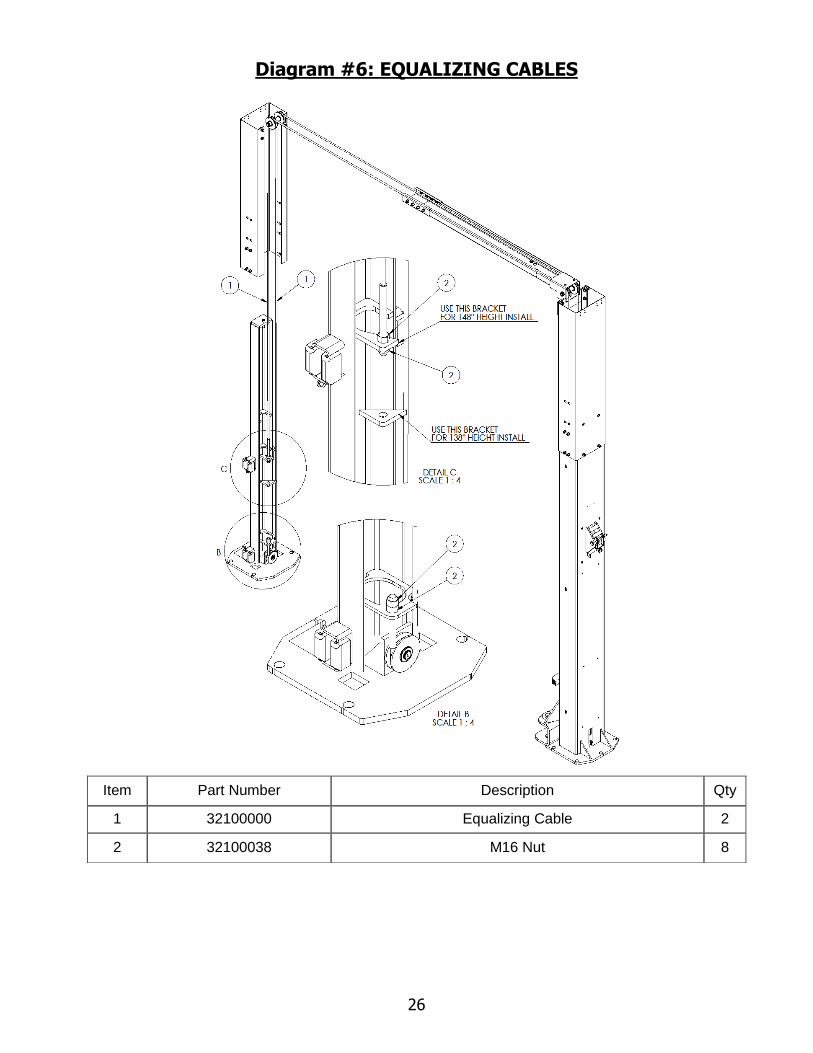
8. One equalizing cable comes partially installed on each carriage. Before feeding a cable up
its column to the overhead crossmember, insure the cable is properly seated around the
lower pulley at the base of each column (reference diagram #6). Route each cable up its
column, over the appropriate pulleys in the overhead crossmember, and lower it down to
the opposite carriage. Insure both equalizing cables are properly seated in overhead
crossmember pulleys. Thread one nut to its farthest point on each equalizing cable. Insert
threaded end into appropriate location on the carriage. Install and hand tighten second
nut to secure each cable. Final equalizing cable adjustment is step 17. Install two bolts
and nuts to prevent unintentional cable displacement.
9. Completely tighten both sides of the overhead crossmember to its column.

12
10. Identify component parts for the safety release cable. Install safety release cable so that
safety locks in both columns will completely disengage when lift is lowered. Final safety
release cable adjustment is step 16.
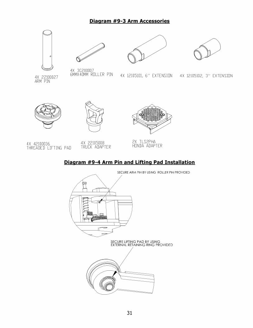
11. Identify parts to install arms (reference diagram #11). Install all 4 arms and arm pins.
Secure each arm pin by inserting roll pin provided. Adjust arm restraint to make sure it
works properly.
12. Install rubber mounts on powerpack bracket (reference diagram #13). Keep these rubber
mounts between the powerpack and the mounting bracket
13. Identify parts for hydraulic system installation (reference diagram #12). Tightly fasten
hydraulic lines to "T" fitting. Locate "T" assembly in overhead crossmember and route
the appropriate lines to cylinders and powerpack. Tightly fasten all hydraulic lines and
secure these lines to both columns and overhead crossmember using hardware. Insure
that nothing will rub or wear the hydraulic lines.
14. NOTE: this should be performed by a licenced electrician. Attach microswitch to
overhead safety bar bracket on powerpack side of overhead crossmember. Wire overhead
safety bar micro-switch to the powerpack. Wire powerpack to shop electrical system.
15. Fill powerpack reservoir with ISO 32 hydraulic oil. Make sure black venting plug is
attached at the top of the reservoir. Attach red plug at the bottom of the
reservoir.
16. Operate the lift with no vehicle and no other weight. Raise lifting carriages
approximately 30 inches (760mm). Confirm that safety locks on both sides engage
properly while lift is being raised. Verify that both lifting cylinders are properly seated in
the baseplate locator hole. Continue raising lift to full height confirming safety locks are
engaging. Adjust safety release cable to insure safety locks can be completely disengaged
while lowering lift (reference diagram #7). Insure that no people or obstacles are near the
lift when adjusting the safety release cable. Lower lift completely. Raise and lower the
lift at least three times or until all air in the hydraulic system is removed.
17. After confirming that all air has been bled from the hydraulic system, adjust equalizing
cable tension as follows: (also reference diagram #6).
Step 1) Hold top of threaded stud with a wrench to prevent it from rotating.

13
Step 2) Tighten nut "B" until all loose slack is removed from the cable. Do not over
tighten.
Step 3) Firmly tighten nut "A" to lock cable in place. Repeat this process for the other
cable insuring both cables have the same degree of tightness.
18. Raise lifting carriages approximately 12 inches (300mm) off the floor. Choose one arm
and align arm restraint gear with locking plunger insuring both components mesh
smoothly and totally. Completely tighten all arm restraint gear locking bolts to maintain
this position. Lower carriage to the floor to insure arm restraint disengages in the down
position. Raise the lift 12 inches (300mm) off the floor to insure arm restraint engages
smoothly and totally. Repeat this process with the remaining 3 arms. Raise and lower
the lift once more to confirm all arm restraints totally engage and disengage smoothly.
19. Install safety lock cover on each column (reference diagram #14).
20. The installation is now complete. Insure that all lift operators are trained in all
points covered by ALI-WL101 label kit (they are applied at the factory).
Final Checkout Procedure of Assembled Lift
✓ Important: Check if carriage clears hydraulic hoses when fully raised! Fail to do
this may cause hydraulic line damage.
✓ Check hydraulic oil level in reservoir. Confirm hydraulic connections are tight with no leaks
✓ Confirm that both columns are level and properly shimmed with all anchor bolts torqued
to 150 ft.-lbs. (204Nm). Confirm lift stability
✓ Confirm that all electrical components have been wired properly and are operational
✓ Confirm that all cables are adjusted properly
✓ Confirm safety locks and arm restraints are functioning properly
✓ Lubricate all lubrication points
✓ Check all the functions with a representative vehicle. (follow the instructions “LIFT
OPERATIONAL TEST WITH A TYPLICAL VECHICLE”)

14
OPERATING INSTRUCTIONS & LIFT MAINTENANCE
LIFT OPERATION:
Before lifting a vehicle, insure all operators are qualified, have been trained and are following
all safety instructions. Read and follow the ALI "Lifting It Right" manual included with the
lift. Always use the "Vehicle Lifting Points" reference guide when lifting a. Insure all
materials stay up to date »» www.autolift.org/ (see example of SAE J2184 standard below)
Insure the vehicle is securely positioned on the lift using manufacturer's recommended lifting
points. Insure all arm restraints are totally engaged. Never allow anyone under the lift when
raising or lowering it with or without a vehicle. Always confirm safety locks on both sides of
the lift are completely engaged before proceeding under a vehicle.
Lift electrical operating controls are located on the powerpack (one "up" button for raising the
lift and one "down" lever for lowering the lift). Before lowering, slightly raise the lifting carriages
to release pressure from both safety locks. Two hands must be used when lowering the lift.
One hand must operate the safety lock release lever (located on the column above the
powerpack) and one hand must operate the "down" lever. Make certain the safety locks do
not accidentally re-engage while lift is being lowered. Customers and bystanders should not
be in the lift area.

15
LIFT OPERATIONAL TEST WITH A TYPICAL VECHILE:
To Raise Vehicle
1. Lower carriages to the floor position.
2. Retract lifting arms to minimum length.
3. Swing arms away from the path of the vehicle.
4. During loading or spotting, center the vehicle between the columns as shown in figure
above.
5. Swing arms under the vehicle. Position the vehicle support pads at the VEHICLE
MANUFACTURES RECOMMENDED LIFTING POINTS. Beginning with some 1994 year
models, auto makers will identify recommended lift points by placing a label on the
vertical lock face plate of the front passenger side door. (ANSI/SAE J2184-OCT92)
6. Clear area around the lift.
7. Raise the vehicle until the vehicle support pads are in full contact, approximately 12
inches (300mm) off floor. Check to see that vehicle is stable on the lift by moderately
rocking the bumper. Recheck the position of the pads for any movement.
8. Raise the vehicle to the desired working elevation and release control button.
9. Lower lifting carriages until they completely contact the mechanical safety locks. The
vehicle is now ready for service.
To Lower Vehicle
WARNING: No one shall be under the vehicle when lowering.
1. Clear area around and under the lift of obstructions and warn personnel to stand clear.
2. Raise vehicle by at least 3 inches (76mm).
3. Pull the safety cable release lever all the way down.
4. While keep the safety release lever pulled, push lower lever on the power unit to lower
the lift.
5. Lower the lift until arms have bottomed and are clear of the lifting points.
6. Swing the lifting arms from beneath the vehicle and fully retract the arms.
7. Remove the vehicle.

16
LIFT MAINTENANCE SCHEDULE
Before maintaining, servicing or repairing the lift, insure that an acceptable "lock out/tag
out” device is activated. The following minimum maintenance schedule must be performed
by the owner or lift operator.
DAILY
✓ Raise and lower the lift without vehicle to verify operations and carriage levels.
✓ Confirm all arm restraints engage and disengage smoothly and totally and telescoping arms
have no excessive movement.
✓ Check all hydraulic fittings and lines for damage or leaks.
✓ Check electrical wiring for damage.
✓ Check all moving parts for uneven or excessive wear.
✓ Repair or replace all damaged, worn, or broken components immediately.
✓ Remove oil/grease on all lift pads.
WEEKLY
✓ Check hydraulic fluid in powerpack reservoir. (Confirm no leaks before topping up)
✓ Check equalizing cable adjustment. Check safety lock release cable adjustment.
MONTHLY
✓ Check that all anchor bolts are torqued to 150 ft.-lbs. (204N-m).
✓ Clean and lubricate arm restraints. (Confirm all components are in good condition)
✓ Lubricate safety locks in both columns.
✓ Check that overhead safety shutoff is operating properly.
EVERY TWO MONTHS
✓ Remove and grease arm pins – reinstall insuring secure fit.
✓ Clean and re-grease slide block channel in both columns.
✓ Clean and lubricate all cable pulleys.
EVERY YEAR
✓ Arrange for a Trained Lift Service Person to inspect and certify all aspects of the lift as per
"Automotive Lift Operation, Inspection and Maintenance" (ALOIM) guidelines.
✓ Confirm that both equalizing cables meet the standard outlined on page 13.
EVERY TWO YEARS
✓ Change and replace hydraulic oil in powerpack reservoir.

17
LUBRICATION
✓ Where grease is required use a multi-purpose lithium grease
✓ Where lubricating oil is required use WD-40 or a SAE 30 oil
✓ Where hydraulic oil is required use ISO 32 – 10W non detergent hydraulic oil.

18
Cable Inspection
The following criteria will determine when an equalizing cable is no longer
acceptable for service:
• 12 randomly distributed broken wires in one lay or four broken wires in one strand
in one lay in running ropes
• one outer wire broken at the contact point with the core of the rope, which has
worked its way out of the rope structure and protrudes or loops out from the rope
structure
• wear of one-third the original diameter of outside individual wires
• kinking, crushing, birdcaging, or any other damage resulting in distortion of the
rope structure
• evidence of heat damage from any cause
• reduction from nominal diameter greater than those listed in the following table:
Rope Diameter Max. Allowable Reduction
5/16’’ (8 mm) or less 1/64’’ (0.4 mm)
5/16’’ (8 mm) to 1/2’’ (12 mm) 1/32’’ (0.8 mm)
1/2’’ (1 2mm) to 3/4’’ (19 mm) 3/64’’ (1.2 mm)
• Attention shall be given to end connections. Upon development of two broken
wires adjacent to socket end connections, the rope shall be re-socketed or
replaced. Re-socketing shall not be attempted if the resulting rope length will be
insufficient for proper operation.
• If any of the cable is as shown in the following pictures, do not use.

19
LIFT PROBLEM TROUBLESHOOTING GUIDE
The following are some suggestions to consider if problems are encountered with the lift.
Please call a Trained Lift Service Person for further clarification and information.
• Lift does not operate: Possibilities include: blown fuse or tripped circuit
breaker, defective "up" button. Call a qualified electrician for all wiring questions.
• Motor runs but lift does not rise: Possibilities include: low hydraulic oil level
(check reservoir tank), dirt under check valve (press "down" lever and "up" button
at the same time for 10-15 seconds. This will clear small contaminants. If this fails
clean check valve ball and seat by removing valve cover). Call a Trained Lift
Service Person if problem continues.
• Motor noise (drone or hum) but will not run: Possibilities include: low
voltage, faulty wiring or faulty capacitor (call electrician to confirm), lift is
overloaded (insure vehicle weighs less than rated lift capacity).
• Lift falters or jerks when it is raised or lowered: Possibilities include: air in
the hydraulic system, cycle lift all the way to the top and completely lower 3 – 4
times. If this does not solve the problem call a Trained Lift Service Person.
• Excessive noise when raising or lowering lift: Possibilities include: pulley
assemblies need lubricating, cable is off the pulleys, carriage sliders need grease,
carriage sliders are broken. Do not operate the lift with broken or damaged
carriage sliders or dislodged cable. Replace immediately.
• Lifting carriages are unequal when raised: Possibilities include: improperly
adjusted equalization cables, air in the hydraulic system. Adjust cables or call a
Trained Lift Service Person to correct the problem.
NOTE: Replace all worn or broken parts and components only with
manufacturer approved/supplied parts and components
Replacement parts may be purchased from your local lift supplier or
the manufacturer at 1 - 877 - 799 - LIFT (5438) or (905) 847 - 1198
20
LIFT ILLUSTRATIONS & PARTS LISTS
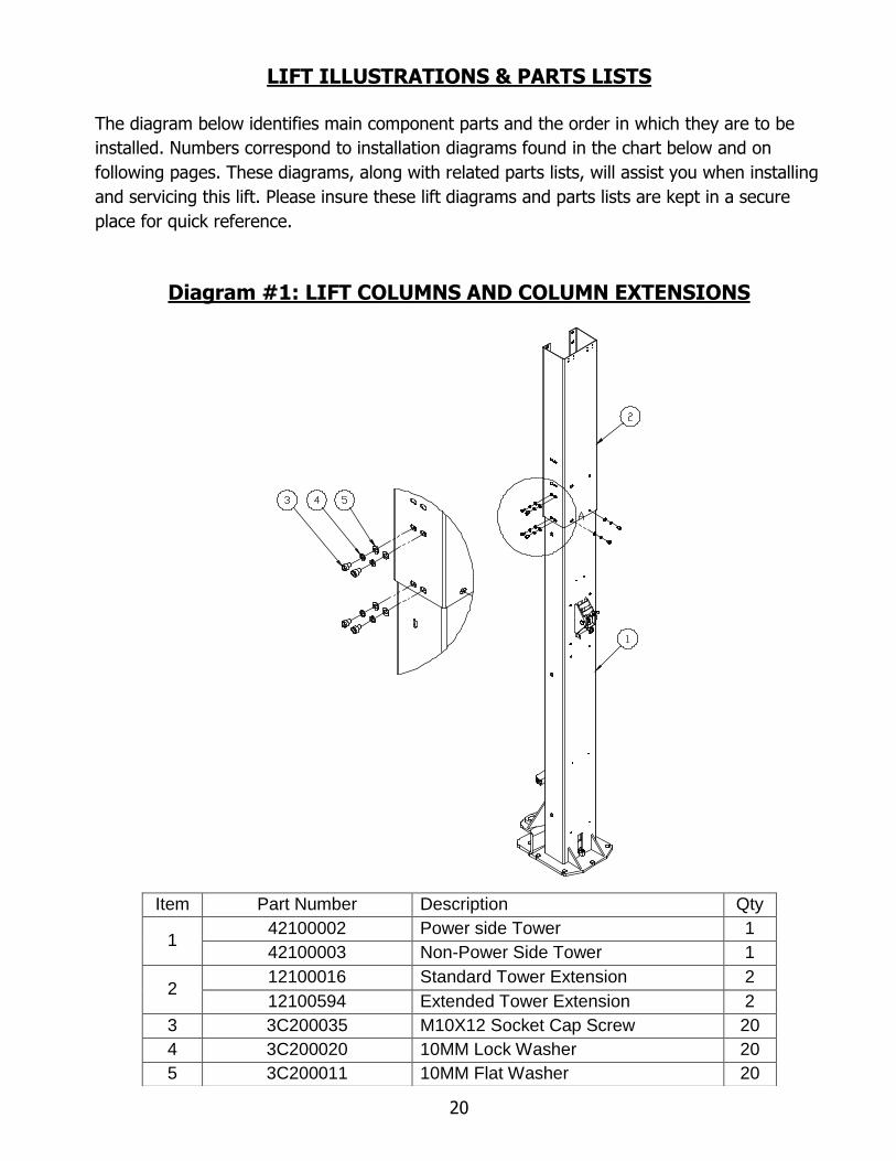
The diagram below identifies main component parts and the order in which they are to be
installed. Numbers correspond to installation diagrams found in the chart below and on
following pages. These diagrams, along with related parts lists, will assist you when installing
and servicing this lift. Please insure these lift diagrams and parts lists are kept in a secure
place for quick reference.
Diagram #1: LIFT COLUMNS AND COLUMN EXTENSIONS
Item Part Number Description Qty
1 42100002 Power side Tower 1
42100003 Non-Power Side Tower 1
2 12100016 Standard Tower Extension 2
12100594 Extended Tower Extension 2
3 3C200035 M10X12 Socket Cap Screw 20
4 3C200020 10MM Lock Washer 20
5 3C200011 10MM Flat Washer 20

21
Diagram #2: LIFT TOWER ASSEMBLY
Item Part Number Description Qty
1 22100032 Non-Power Side Tower Weldment 1
2 12100018 Safety Shaft 2
3 32100032 24MM Flat Washer 2
4 12100078 Torsion Spring 2
5 12100020 Spacer 4
6 12100021 Safety Release Cable Clamp 2
7 12100022 Lock Release Channel (Non-power side) 1
22100035 Lock Release Channel Weldment (Power side) 1
8 12100098 Equalizing Pulley 6
9 32100004 Bushing 2
10 32100005 Bushing 2
11 12100023 Safety Release Pulley Mount 1
12 12100044 Safety Pulley 3
13 12100086 Safety Lock 2
14 32100551 Thrust Washer 2
15 32100537 20MM Snap Ring 2
16 32100538 25MM Snap Ring 4
17 32100539 M8 Nut 4
18 32100540 M6 Bolt 2
19 32100541 6MM Washer 2
20 32100542 M6 Screw 2
21 22100031 Power Side Tower Weldment 1
22 12100025 Lever 1
23 32100040 Plastic Ball 1

22
Diagram #3: CARRIAGE ASSEMBLY
Item Part Number Description Qty
1 22100011 Carriage Weldment 2
2 12100145 Door Guard 2
3 12100027 Carriage Slider 16
4 12100028 Arm Lock Plunger 4
5 12100029 Arm Lock (Inner Gear) 4
6 12100030 Arm Lock Spring 4
7 12100081 Slider Shim 16
8 32100533 Roller Pin 8
9 32100534 M8 Bolt 4
10 32100535 8MM Washer 4
23
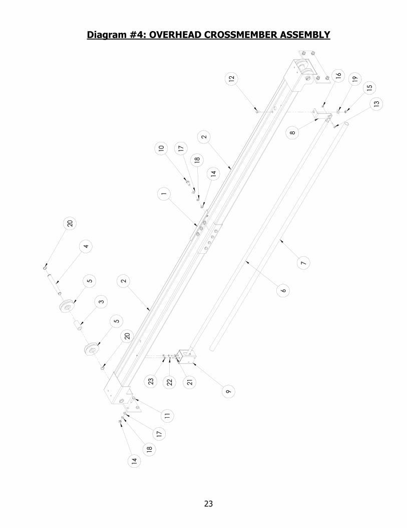
Diagram #4: OVERHEAD CROSSMEMBER ASSEMBLY

24
Item Part Number Description Qty
1 12100095/12100231 Standard/Wide Overhead Channel Brace 1
2 22100037 Half Crossbeam Weldment 2
3 12100096 Pulley Spacer 2
4 12100097 Overhead Pulley Shaft 2
5 12100098 Equalizing Pulley 6
6 22100014 Overhead Shut-off Bar 1
7 12100103 Foam 1
8 12100102 Overhead Shut-off Mounting Bracket 1
9 42100010 Overhead Shut-off Micro Switch 1
10 32100530 M10X25 Bolt 8
11 32100531 M10X30 Bolt 8
12 32100020 M8X16 Bolt 1
13 32103035 M6 Bolt 1
14 32100532 M10 Nut 16
15 32100027 M8 Nut 1
16 32103036 M6 Nut 1
17 32100506 10MM Flat Washer 16
18 32100507 10MM Lock Washer 16
19 32100044 10MM Flat Washer 1
20 32100034 20MM Retaining Ring 4
21 32100025 M6X25 Bolt 2
22 32100026 6MM Lock Washer 2
23 32103026 M6 Nut 2

25
Diagram #5: LIFT LEVELLING - COLUMN SHIMING - ANCHOR BOLTS
Item Part Number Description Qty
1 3000539 3/4" Concrete Anchor 10
2 3000540 Shim-6mm 10
3 3000541 Shim-3mm 10
4 3000542 Shim-1mm 10
26
Diagram #6: EQUALIZING CABLES
Item Part Number Description Qty
1 32100000 Equalizing Cable 2
2 32100038 M16 Nut 8

27
Diagram #7: SAFETY RELEASE CABLE
Item Part Number Description Qty
1 32100001/12100593 Safety Release Cable/Extended Model Cable 1
2 42100033 Safety Cable Guide Assembly 2

28
Diagram #8: SAFETY CABLE GUIDE ASSEMBLY
Item Part Number Description Qty
1 12100024 Pulley Bracket 2
2 12100044 Safety Release Pulley 3
3 32100543 M6 Bolt 2
4 32100544 M6 Lock Nut 2
5 32100545 M6 Bolt 4
6 32100546 6MM Washer 8
7 32100547 6MM Lock Washer 4
8 32100548 M6 Nut 4

29
Diagram #9: LIFT ARMS AND ARM RESTRAINTS
Diagram #9-1 Front Arm (Driver Side: 42105004, Passenger Side: 42105003)
Item Part Number Description Qty
1 22105005 Driver Side Front Outer Arm Weldment 1
22105003 Passenger Side Front Outer Arm Weldment 1
2 22105006 Driver Side Front Middle Arm Weldment 1
22105002 Passenger Side Front Middle Arm Weldment 1
3 22105007 Driver Side Front Inner Arm Weldment 1
22105001 Passenger Side Front Inner Arm Weldment 1
4 12100050 Arm Lock Gear 4
5 3C200011 10MM FLAT WASHER 12
6 3C200020 10MM LOCK WASHER 12
7 3C200018 M10X35 HEX BOLT 12
8 3C200012 M10 NUT 8
9 3C200019 M10X25 SOCKET SCREW 8

30
Diagram #9-2 Rear Arm (Driver Side: 42105001, Passenger Side: 42105002)
Item Part Number Description Qty
1 22100039 Driver Side Rear Outer Arm Weldment 1
22100040 Passenger Side Rear Outer Arm Weldment 1
2 22105015 Driver Side Rear Middle Arm Weldment 1
22105016 Passenger Side Rear Middle Arm Weldment 1
3 22105014 Driver Side Rear Inner Arm Weldment 1
22105013 Passenger Side Rear Inner Arm Weldment 1
4 12100050 Arm Lock Gear 4
5 3C200011 10MM FLAT WASHER 12
6 3C200020 10MM LOCK WASHER 12
7 3C200018 M10X35 HEX BOLT 12
8 3C200012 M10 NUT 8
9 3C200019 M10X25 SOCKET SCREW 8
31
Diagram #9-3 Arm Accessories
Diagram #9-4 Arm Pin and Lifting Pad Installation
32
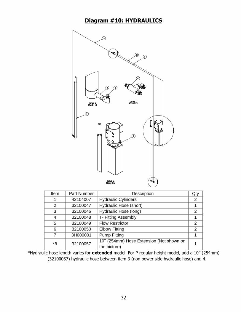
Diagram #10: HYDRAULICS
*Hydraulic hose length varies for extended model. For P regular height model, add a 10’’ (254mm)
(32100057) hydraulic hose between item 3 (non power side hydraulic hose) and 4.
Item Part Number Description Qty
1 42104007 Hydraulic Cylinders 2
2 32100047 Hydraulic Hose (short) 1
3 32100046 Hydraulic Hose (long) 2
4 32100048 T- Fitting Assembly 1
5 32100049 Flow Restrictor 2
6 32100050 Elbow Fitting 2
7 3H000001 Pump Fitting 1
*8 32100057 10’’ (254mm) Hose Extension (Not shown on
the picture) 1

33
Diagram #11: POWERPACK INSTALLATION
Item Part Number Description Qty
1 32100002 Power Unit 1
2 12100541 Power Unit Mounting Rubber 4
3 32100522 8MM Lock Washer 4
4 32100524 M8 Nut 4
34
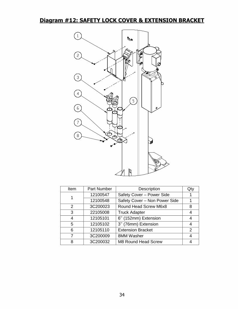
Diagram #12: SAFETY LOCK COVER & EXTENSION BRACKET
Item Part Number Description Qty
1 12100547 Safety Cover – Power Side 1
12100548 Safety Cover – Non Power Side 1
2 3C200023 Round Head Screw M6x8 8
3 22105008 Truck Adapter 4
4 12105101 6’’ (152mm) Extension 4
5 12105102 3’’ (76mm) Extension 4
6 12105110 Extension Bracket 2
7 3C200009 8MM Washer 4
8 3C200032 M8 Round Head Screw 4

35
Diagram #13: SAFETY INSTRUCTION and INFORMATION
DECAL KIT LOCATION
Individual Decals to Powerpack
Column in clear view of operator Powerpack Column in clear view
of operator

36
Diagram #14: WIRING DIAGRAM (1PH MOTOR)

37
Diagram #15: SAFETYBAR COLLAR INSTALLATION(Optional)