Embed Size (px)
Citation preview

Connectivity | Process AutomationATEX/IECEx ApprovedMinifast Connectors
B2050-ATEX
Your Global Automation Partner

2 Turck Inc. | 3000 Campus Drive, Minneapolis, MN 55441 | T +1 800 544 7769 | F +1 763 553 0708 | www.turck.com
ATEX Approved Minifast HD (Heavy Duty) Cordsets Part Number Key
Connectivity | Process Automation
Part Number Keys are to assist in IDENTIFICATION ONLY. Consult factory for catalog items not identified.
Process Cordset
P - X - R S V Z R K V Z 40-1188XL - *M
Length in meters
GenderK = FemaleS = Male
ConfigurationR = StraightW = Right angle
Compliancy ApprovalsX = ATEX Category 3 and US Zone 2 ApprovalX1 = ATEX Category 3 ApprovalX2 = US Zone 2 Approval
Coupling nut/body optionsV = Stainless steel
Number of wires/AWG/Color Codes/Cable Type30-1188XL = 3x18 AWG BU, BN, Drain, Extremelife-6031-1188XL = 3x18 AWG BU, BN, GN/YE, Extremelife-6040-1188XL = 3x18 AWG BU, BN, Drain, GN/YE, Extremelife-6052-2314XL = 5x18 AWG BK, WH, GY, BN, BU, Extremelife-60561-2176XL = 5x18 AWG BU, BN, GN/YE, WH, BK, Extremelife-6066-2176XL = 5x18 AWG BU, BN, GN/YE, WH, BK, Drain, Extremelife-60
101-1189XL = 9x18 AWGWH/BK, BK/WH, WH/GN, GN/WH, WH/RD, RD/WH, Drain, GN/YE, WH/OR, OR/WH, Extremelife-60
190-1484XL = 16x22 AWG, 18 AWG GND
WH/BK, BK/WH, WH/GN, GN/WH, Drain, WH/RD, N/C, RD/WH, WH/OR, OR/WH, WH/BU, GN/YE, BU/WH, WH/BN, BN/WH, WH/YE, YE/WH, WH/VO, VO/WH, Extremelife-60
Insertion point of extension cable and 2nd prefixMale connector listed 1st, female connector 2nd
ATEX Approved Minifast Receptacles Part Number Key
P - X - R K F V 40 - *M /14.5/NPT
Mounting Thread Type/14.5/NPT = 1/2-14 NPT threads/14.75/NPT = 3/4-14 NPT threads/M20 M20x1 threads
Process Cordset
GenderK = FemaleS = Male
Minifast Receptacle
Compliancy ApprovalsX = ATEX Category 3 and US Zone 2 Approval
Housing MaterialV = Stainless steel
Designator for Receptacle
Length in meters
Connector Body Size(Blank) = Standard body
= B-Size Minifast plug body, A-Size Minifastconnector thread
Body styleZ = Potted metal body
Number of wires/AWG/Color Codes30 = 2x18 AWG BU, BN31 = 3x18 AWG BU, BN, GN/YE40 = 3x18 AWG BU, BN, N/C, GN/YE52 = 5x18 AWG BK, WH, GY, BN, BU561 = 5x18 AWG BU, BN, GN/YE, WH, BK66 = 5x18 AWG BU, BN, GN/YE, WH, BK
100 = 9x18 AWG WH/BK, BK/WH, WH/GN, GN/WH, WH/RD, RD/WH, N/C, GN/YE, WH/OR, OR/WH
190 = 16x22 AWG, 2x18 AWG
WH/BK, BK/WH, WH/GN, GN/WH, GY, WH/RD, N/C, RD/WH, WH/OR, OR/WH, WH/BU, GN/YE, BU/WH, WH/BN, BN/WH, WH/YE, YE/WH, WH/VO, VO/WH

3 Turck Inc. | 3000 Campus Drive, Minneapolis, MN 55441 | T +1 800 544 7769 | F +1 763 553 0708 | www.turck.com
Part Number ApplicationImage Reference Pinout Cable Specifications Electrical Ratings Pinout Color
P-X-RKVZ 30-1188XL-*M 2-wire + drain, female A 1 EX60 black cable jacket, 3x18 AWG,1 STP with GND, Foil/Drain (20), 8.5 mm OD,Cable #RF51188
8 amps, 250 volts ITC/PLTC: 5 amps, 150 volts
1.BU 2.BN 3.Drain
P-X-RSVZ 30-1188XL-*M 2-wire + drain, male B 2
P-X-RSVZ RKVZ 30-1188XL-*M 2-wire + drain, female to male extension A,B 1,2
P-X-RKVZ 31-1188XL-*M 3-wire, female A 1 EX60 black cable jacket, 3x18 AWG, 1 STP with GND, Foil/Drain (20), 8.5 mm OD,Cable #RF51188
8 amps, 250 volts ITC/PLTC: 5 amps, 150 volts
1.BU 2.BN 3.GN/YE
P-X-RSVZ 31-1188XL-*M 3-wire, male B 2
P-X-RSVZ RKVZ 31-1188XL-*M 3-wire, female tomale extension A,B 1,2
P-X-RKVZ 40-1188XL-*M 3-wire + drain, female A 3 EX60 black cable jacket, 3x18 AWG, 1 STP with GND, Foil/Drain (20), 8.5 mm OD,Cable #RF51188
8 amps, 250 volts ITC/PLTC: 5 amps, 150 volts
1.BU 2.BN 3.Drain 4.GN/YE
P-X-RSVZ 40-1188XL-*M 3-wire + drain, male B 4
P-X-RSVZ RKVZ 40-1188XL-*M 3-wire + drain, female to male extension A,B 3,4
P-X-RKVZ 52-2314XL-*M 5-wire, female A 5EX60 black cable jacket, 5x18 AWG, 10.0 mm OD, Cable #RF52314
8 amps, 250 volts ITC/PLTC: 5 amps, 150 volts
1.BK 2.WH 3.GY 4.BN 5.BU
P-X-RSVZ 52-2314XL-*M 5-wire, male B 6
P-X-RSVZ RKVZ 52-2314XL-*M 5-wire, female tomale extension A,B 5,6
P-X-RKVZ 561-2176XL-*M 5-wire, female A 5EX60 black cable jacket, 5x18 AWG, 10.4 mm OD, Cable #RF52176
8 amps, 250 volts ITC/PLTC: 5 amps, 150 volts
1.BU 2.BN 3.GN/YE 4.WH 5.BK
P-X-RSVZ 561-2176XL-*M 5-wire, male B 6
P-X-RSVZ RKVZ 561-2176XL-*M 5-wire, female tomale extension A,B 5,6
P-X-RKVZ 66-2176XL-*M 5-wire + drain, female A 7EX60 black cable jacket, 5x18 AWG, 2 STP with GND, Foil/Drain (20), 10.4 mm OD,Cable #RF52176
8 amps, 250 volts ITC/PLTC: 5 amps, 150 volts
1.BU 2.BN 3.GN/YE 4.WH 5.BK 6.Drain
P-X-RSVZ 66-2176XL-*M 5-wire + drain, male B 8
P-X-RSVZ RKVZ 66-2176XL-*M 5-wire + drain, female to male extension A,B 7,8
P-X-RKVZ 101-1189XL-*M 9-wire + drain, female C 9 EX60 black cable jacket, 9x18 AWG, 4 STP with GND, Foil/Drain (20), 13.2 mm OD,Cable #RF51189
7 amps, 250 volts ITC/PLTC: 5 amps, 150 volts
1.WH/BK 6.RD/WH 2.BK/WH 7.Drain 3.WH/GN 8.GN/YE 4.GN/WH 9.WH/OR 5.WH/RD 10.OR/WH
P-X-RSVZ 101-1189XL-*M 9-wire + drain, male D 10
P-X-RSVZ RKVZ 101-1189XL-*M 9-wire + drain, female to male extension C,D 9,10
ATEX Approved Minifast HD (Heavy Duty) Cordsets
Cable FeaturesCable Jacket Material: Extremelife-60UL Listings: TC-ER/ITC-ER/PLTC-ER or ITC-ER/PLTC-ERUL/CSA Listings: CIC/TC or CICAdditional Approvals: -40 °C Cold Impact, -60 °C Cold BendShipboard Approvals: UL 1309 Marine Shipboard, ABS Certified, IEEE 1202/FT4, IEEE 1580IEC Flame Compliance: IEC 60332-3-22Cable Temperature Rating: -60 to +105 °COil and Sunlight Resistant
Connectivity | Process Automation
Product HighlightsApproved for ATEX Category 3 hazardous locationsApproved for US Zone 2 hazardous locationsElectrical connection conforms to ANSI B93.55M-1981 & SAE H1738-2316 stainless steel body and coupling nutNEMA 1,3,4,6P and IEC IP67, IP68
We
rese
rve
the
right
to m
ake
tech
nica
l alte
ratio
ns w
ithou
t prio
r not
ice.
* Length in meters. Standard cable lengths are 2, 4, 6, 8 and 10 meters. Consult factory for other lengths.See Turck control drawing Ni-2.422 for guidance on installation in hazardous locations.Use with Lockfast guards for approved installation in hazardous locations (see pg. 11 for available Lockfast guards).

4 Turck Inc. | 3000 Campus Drive, Minneapolis, MN 55441 | T +1 800 544 7769 | F +1 763 553 0708 | www.turck.com
Dimension Drawings
A B
2.910 [73.9] ø1.063 [27.0]
7/8-16UN
2.958 [75.1] ø1.063 [27.0]
7/8-16UN
C D
1 1/8-16UN
3.642 [92.5] ø1.240 [31.5]
1 1/8-16UN
3.681 [93.5] ø1.240 [31.5]
ATEX Approved Minifast HD (Heavy Duty) Cordsets (continued)
Connectivity | Process Automation
Pinouts
1 2 3 4 5 6
Female 3 pin Male 3 pin Female 4 pin Male 4 pin Female 5 pin Male 5 pin
7 8 9 10 11 12
Female 6 pin Male 6 pin Female 10 pin Male 10 pin Female 19 pin Male 19 pin
Part Number ApplicationImage Reference Pinout Cable Specifications Electrical Ratings Pinout Color
P-X-RKVZ 190-1484XL-*M 17-wire + drain, female C 11
EX60 black cable jacket, 16X22 AWG, 18 AWG GND, 8 STP, Foil/Drain (22), 13.7 mm OD, Cable #RF51484
2 amps, 150 volts ITC/PLTC: 2 amps, 150 volts
1.WH/BK 11.WH/BU 2.BK/WH 12.GN/YE 3.WH/GN 13.BU/WH 4.GN/WH 14.WH/BN 5.Drain 15.BN/WH 6.WH/RD 16.WH/YE 7.N/C 17.YE/WH 8.RD/WH 18.WH/VO 9.WH/OR 19.VO/WH 10.OR/WH
P-X-RSVZ 190-1484XL-*M 17-wire + drain, male D 12
P-X-RSVZ RKVZ 190-1484XL-*M 17-wire + drain, female to male extension C,D 11,12
We reserve the right to m
ake technical alterations without prior notice.

5 Turck Inc. | 3000 Campus Drive, Minneapolis, MN 55441 | T +1 800 544 7769 | F +1 763 553 0708 | www.turck.com
Part Number ApplicationImage Reference Pinout Wire Specifications Electrical Ratings Pinout Color
P-X-RKFV 30-*/14.5/NPT 2-wire, female,1/2” NPT mounting A
1
2x18 AWG, UL, CSA8 amps, 250 volts ITC/PLTC: 5 amps, 150 volts
1.BU 2.BN 3.N/C
P-X-RKFV 30-*/14.75/NPT 2-wire, female,3/4” NPT mounting B
P-X-RKFV 30-*/M20 2-wire, female,M20 mounting C
P-X-RSFV 30-*/14.5/NPT 2-wire, male,1/2” NPT mounting D
2P-X-RSFV 30-*/14.75/NPT 2-wire, male,3/4” NPT mounting E
P-X-RSFV 30-*/M20 2-wire, male,M20 mounting F
P-X-RKFV 31-*/14.5/NPT 3-wire, female,1/2” NPT mounting A
1
3x18 AWG, UL, CSA8 amps, 250 volts ITC/PLTC: 5 amps, 150 volts
1.BU 2.BN 3.GN/YE
P-X-RKFV 31-*/14.75/NPT 3-wire, female,3/4” NPT mounting B
P-X-RKFV 31-*/M20 3-wire, female,M20 mounting C
P-X-RSFV 31-*/14.5/NPT 3-wire, male,1/2” NPT mounting D
2P-X-RSFV 31-*/14.75/NPT 3-wire, male,3/4” NPT mounting E
P-X-RSFV 31-*/M20 3-wire, male,M20 mounting F
P-X-RKFV 40-*/14.5/NPT 3-wire, female,1/2” NPT mounting A
3
3x18 AWG, UL, CSA8 amps, 250 volts ITC/PLTC: 5 amps, 150 volts
1.BU 2.BN 3.N/C 4.GN/YE
P-X-RKFV 40-*/14.75/NPT 3-wire, female,3/4” NPT mounting B
P-X-RKFV 40-*/M20 3-wire, female,M20 mounting C
P-X-RSFV 40-*/14.5/NPT 3-wire, male,1/2” NPT mounting D
4P-X-RSFV 40-*/14.75/NPT 3-wire, male,3/4” NPT mounting E
P-X-RSFV 40-*/M20 3-wire, male,M20 mounting F
ATEX Approved Minifast Receptacles
Connectivity | Process Automation
Wire FeaturesWire Jacket Material: PVCWire Temperature Rating: -40 to 105 °C
Product HighlightsApproved for ATEX Category 3 hazardous locationsApproved for US Zone 2 hazardous locationsElectrical connection conforms to ANSI B93.55M-1981 & SAE H1738-2316 stainless steel receptacle housingsNEMA 1,3,4,6P and IEC IP67, IP68
We
rese
rve
the
right
to m
ake
tech
nica
l alte
ratio
ns w
ithou
t prio
r not
ice.
* Length in meters. Standard lead length is 0.3 meters. Consult factory for other lengths.See Turck control drawing Ni-2.422 for guidance on installation in hazardous locations.Use with Lockfast guards for approved installation in hazardous locations (see pg. 11 for available Lockfast guards).
6 Turck Inc. | 3000 Campus Drive, Minneapolis, MN 55441 | T +1 800 544 7769 | F +1 763 553 0708 | www.turck.com
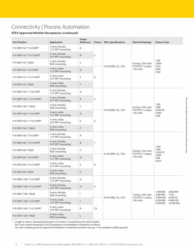
ATEX Approved Minifast Receptacles (continued)
Connectivity | Process Automation
Part Number ApplicationImage Reference Pinout Wire Specifications Electrical Ratings Pinout Color
P-X-RKFV 52-*/14.5/NPT 5-wire, female,1/2” NPT mounting A
5
5x18 AWG, UL, CSA8 amps, 250 volts ITC/PLTC: 5 amps, 150 volts
1.BK 2.WH 3.GY 4.BN 5.BU
P-X-RKFV 52-*/14.75/NPT 5-wire, female,3/4” NPT mounting B
P-X-RKFV 52-*/M20 5-wire, female,M20 mounting C
P-X-RSFV 52-*/14.5/NPT 5-wire, male,1/2” NPT mounting D
6P-X-RSFV 52-*/14.75/NPT 5-wire, male,3/4” NPT mounting E
P-X-RSFV 52-*/M20 5-wire, male,M20 mounting F
P-X-RKFV 561-*/14.5/NPT 5-wire, female,1/2” NPT mounting A
5
5x18 AWG, UL, CSA8 amps, 250 volts ITC/PLTC: 5 amps, 150 volts
1.BU 2.BN 3.GN/YE 4.WH 5.BK
P-X-RKFV 561-*/14.75/NPT 5-wire, female,3/4” NPT mounting B
P-X-RKFV 561-*/M20 5-wire, female,M20 mounting C
P-X-RSFV 561-*/14.5/NPT 5-wire, male,1/2” NPT mounting D
6P-X-RSFV 561-*/14.75/NPT 5-wire, male,3/4” NPT mounting E
P-X-RSFV 561-*/M20 5-wire, male,M20 mounting F
P-X-RKFV 66-*/14.5/NPT 5-wire, female,1/2” NPT mounting A
7
5x18 AWG, UL, CSA8 amps, 250 volts ITC/PLTC: 5 amps, 150 volts
1.BU 2.BN 3.GN/YE 4.WH 5.BK 6.N/C
P-X-RKFV 66-*/14.75/NPT 5-wire, female,3/4” NPT mounting B
P-X-RKFV 66-*/M20 5-wire, female,M20 mounting C
P-X-RSFV 66-*/14.5/NPT 5-wire, male,1/2” NPT mounting D
8P-X-RSFV 66-*/14.75/NPT 5-wire, male,3/4” NPT mounting E
P-X-RSFV 66-*/M20 5-wire, male,M20 mounting F
P-X-RKFV 100-*/14.5/NPT 9-wire, female,1/2” NPT mounting G
9
9x18 AWG, UL, CSA7 amps, 250 volts ITC/PLTC: 5 amps, 150 volts
1.WH/BK 6.RD/WH 2.BK/WH 7.N/C 3.WH/GN 8.GN/YE 4.GN/WH 9.WH/OR 5.WH/RD 10.OR/WH
P-X-RKFV 100-*/14.75/NPT 9-wire, female,3/4” NPT mounting H
P-X-RKFV 100-*/M20 9-wire, female,M20 mounting I
P-X-RSFV 100-*/14.5/NPT 9-wire, male,1/2” NPT mounting J
10P-X-RSFV 100-*/14.75/NPT 9-wire, male,3/4” NPT mounting K
P-X-RSFV 100-*/M20 9-wire, male,M20 mounting L
We reserve the right to m
ake technical alterations without prior notice.
* Length in meters. Standard lead length is 0.3 meters. Consult factory for other lengths.See Turck control drawing Ni-2.422 for guidance on installation in hazardous locations.Use with Lockfast guards for approved installation in hazardous locations (see pg. 11 for available Lockfast guards).
7 Turck Inc. | 3000 Campus Drive, Minneapolis, MN 55441 | T +1 800 544 7769 | F +1 763 553 0708 | www.turck.com
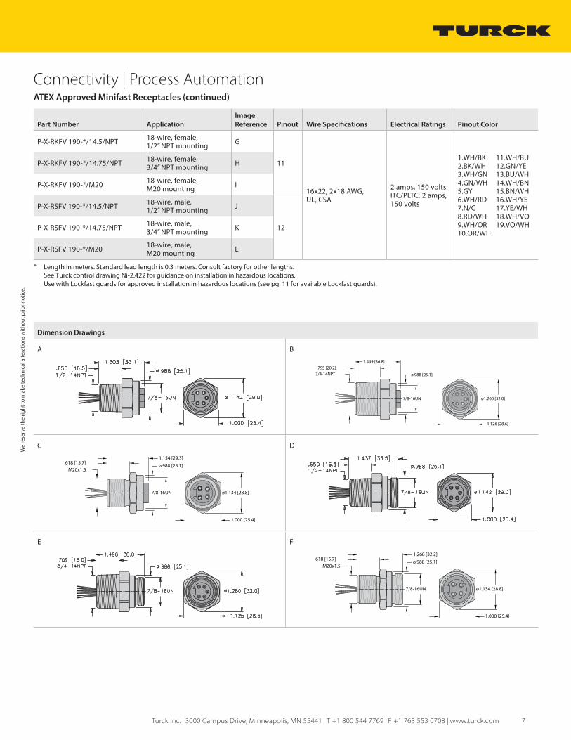
ATEX Approved Minifast Receptacles (continued)
Connectivity | Process Automation
Part Number ApplicationImage Reference Pinout Wire Specifications Electrical Ratings Pinout Color
P-X-RKFV 190-*/14.5/NPT 18-wire, female,1/2” NPT mounting G
11
16x22, 2x18 AWG,UL, CSA
2 amps, 150 volts ITC/PLTC: 2 amps, 150 volts
1.WH/BK 11.WH/BU 2.BK/WH 12.GN/YE 3.WH/GN 13.BU/WH 4.GN/WH 14.WH/BN 5.GY 15.BN/WH 6.WH/RD 16.WH/YE 7.N/C 17.YE/WH 8.RD/WH 18.WH/VO 9.WH/OR 19.VO/WH 10.OR/WH
P-X-RKFV 190-*/14.75/NPT 18-wire, female,3/4” NPT mounting H
P-X-RKFV 190-*/M20 18-wire, female,M20 mounting I
P-X-RSFV 190-*/14.5/NPT 18-wire, male,1/2” NPT mounting J
12P-X-RSFV 190-*/14.75/NPT 18-wire, male,3/4” NPT mounting K
P-X-RSFV 190-*/M20 18-wire, male,M20 mounting L
Dimension Drawings
A B
3/4-14NPT.795 [20.2]
1.449 [36.8]
7/8-16UN
ø.988 [25.1]
ø1.260 [32.0]
1.126 [28.6]
C D
ø1.134 [28.8]
1.000 [25.4]
M20x1.5
7/8-16UN
ø.988 [25.1].618 [15.7]1.154 [29.3]
E F
ø1.134 [28.8]
1.000 [25.4]
M20x1.5
7/8-16UN
ø.988 [25.1].618 [15.7]1.268 [32.2]
We
rese
rve
the
right
to m
ake
tech
nica
l alte
ratio
ns w
ithou
t prio
r not
ice.
* Length in meters. Standard lead length is 0.3 meters. Consult factory for other lengths.See Turck control drawing Ni-2.422 for guidance on installation in hazardous locations.Use with Lockfast guards for approved installation in hazardous locations (see pg. 11 for available Lockfast guards).

8 Turck Inc. | 3000 Campus Drive, Minneapolis, MN 55441 | T +1 800 544 7769 | F +1 763 553 0708 | www.turck.com
ATEX Approved Minifast Receptacles
Connectivity | Process Automation
Dimension Drawings (continued)
G H
I J
K L
Pinouts
1 2 3 4 5 6
Female 3 pin Male 3 pin Female 4 pin Male 4 pin Female 5 pin Male 5 pin
7 8 9 10 11 12
Female 6 pin Male 6 pin Female 10 pin Male 10 pin Female 19 pin Male 19 pin
We reserve the right to m
ake technical alterations without prior notice.

9 Turck Inc. | 3000 Campus Drive, Minneapolis, MN 55441 | T +1 800 544 7769 | F +1 763 553 0708 | www.turck.com
ATEX Approved Minifast Junction BoxesProduct HighlightsApproved for ATEX Category 3 hazardous locationsApproved for US Zone 2 hazardous locationsSimplifies wiring installationsCast aluminum box with black powder coat316 stainless steel connector housingsElectrical connection conforms to ANSI B93.55M-1981 & SAE H1738-2
Connectivity | Process Automation
Dimension Drawings
A B
Part Number ApplicationImage Reference Wiring Connectors Electrical Ratings
P-X-4 RKFV 40-RSFV100 4-port, 1 analog signal per port A 1 Port connectors: 4-pin 7/8” Minifast
Homerun connector: 10-pin 1 1/8” Minifast7 amps per port,8 amps total
P-X-8 RKFV 40-RSFV190 8-port, 1 analog signal per port B 2 Port connectors: 4-pin 7/8” Minifast
Homerun connector: 19-pin 1 1/8” Minifast2 amps per port,8 amps total
We
rese
rve
the
right
to m
ake
tech
nica
l alte
ratio
ns w
ithou
t prio
r not
ice.
See Turck control drawing Ni-2.422 for guidance on installation in hazardous locations.Use with Lockfast guards for approved installation in hazardous locations (see pg. 11 for available Lockfast guards).

10 Turck Inc. | 3000 Campus Drive, Minneapolis, MN 55441 | T +1 800 544 7769 | F +1 763 553 0708 | www.turck.com
ATEX Approved Minifast Junction Boxes
Wiring Diagrams
1 2
Connectivity | Process Automation
Pinouts
Port connector4-port homerun connector
8-port homerun connector
Female 4 pin Male 10 pin Male 19 pin
We reserve the right to m
ake technical alterations without prior notice.
11 Turck Inc. | 3000 Campus Drive, Minneapolis, MN 55441 | T +1 800 544 7769 | F +1 763 553 0708 | www.turck.com
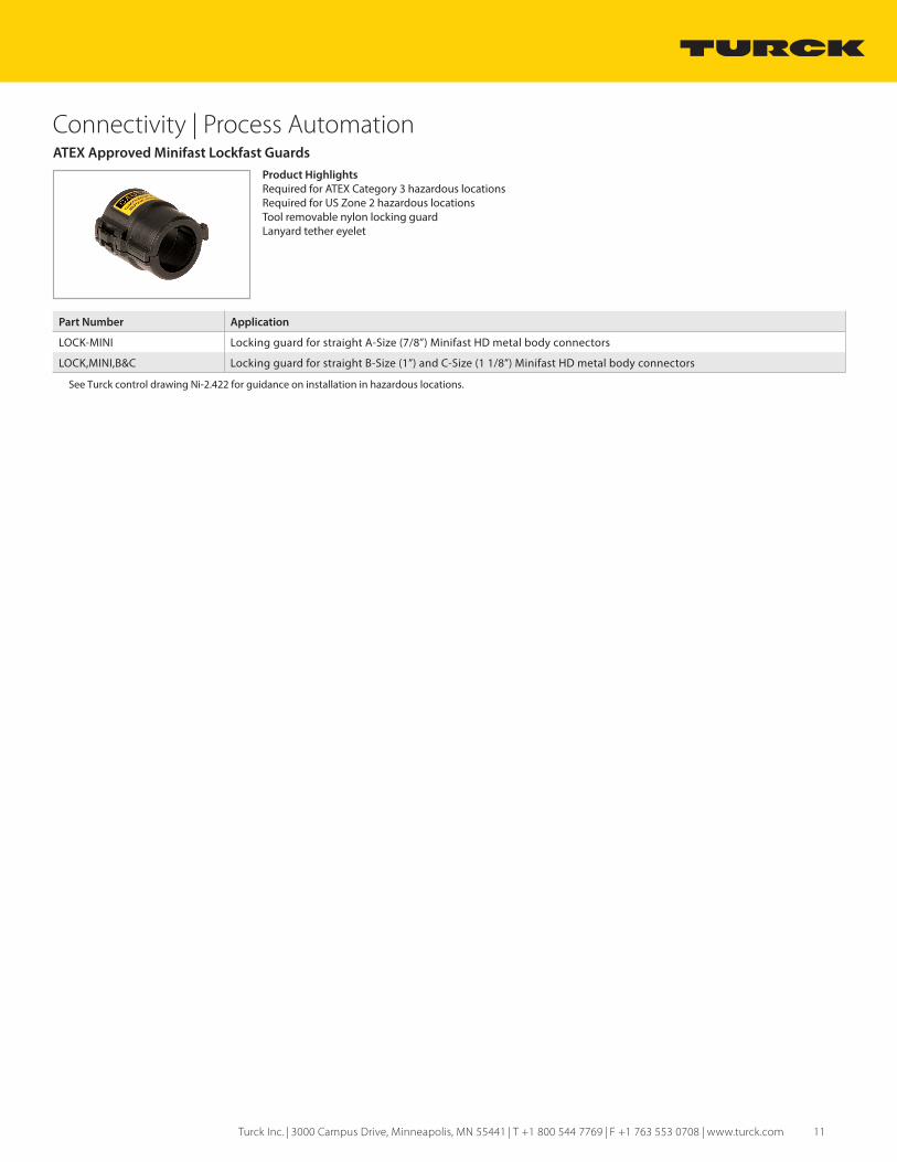
ATEX Approved Minifast Lockfast GuardsProduct HighlightsRequired for ATEX Category 3 hazardous locationsRequired for US Zone 2 hazardous locationsTool removable nylon locking guardLanyard tether eyelet
Connectivity | Process Automation
Part Number Application
LOCK-MINI Locking guard for straight A-Size (7/8”) Minifast HD metal body connectors
LOCK,MINI,B&C Locking guard for straight B-Size (1”) and C-Size (1 1/8”) Minifast HD metal body connectors
See Turck control drawing Ni-2.422 for guidance on installation in hazardous locations.

28 subsidiaries and over 60 representations worldwide!
www.turck.comB2050 A 04/17©2017 by Turck Inc. All rights reserved. No part of the
publication may be reproduced without written permission.
Printed in USA