Embed Size (px)
Citation preview
doc.: IEEE 802.11-15-0043-01-00ax
Submission
January 2015
ETRI
In-band Full Duplex Radios
and System Performance
Date: 2015-01-12
Authors:
Slide 1
Name Affiliations Address Phone email Kapseok Chang ETRI 218 Gajeong-ro, Yuseong-
gu, Daejeon 305-700, Korea
Hyungsik Ju ETRI " [email protected]
Seon-Ae Kim ETRI " [email protected]
Byung-Jae Kwak ETRI " [email protected]
Moon-Sik Lee ETRI " [email protected]
Jimin Bae KAIST 291 Daehak-ro, Yuseong-gu,
Daejeon 305-338, Korea [email protected]
Eunhye Park KAIST " [email protected]
Youngnam Han KAIST " [email protected]
Woojin Ahn Yonsei University [email protected]
Ronny Yongho
Kim
Korea National
University of
Transportation
doc.: IEEE 802.11-15-0043-01-00ax
Submission
January 2015
ETRI
Outline
Feasibility of In-band Full Duplex (IFD) Concept
Merit
Demerit
Classification of self-interference cancellation (SIC) Technology
State of the art in SIC
System Performance Introduction
Duplex mode TDD
3-node form IFD
Pairwise IFD
Residential scenario System-level simulation environment
Evaluation result
Outdoor large BSS scenario System-level simulation environment
Evaluation result
Summary
Slide 2
doc.: IEEE 802.11-15-0043-01-00ax
Submission
January 2015
ETRI
Feasibility of In-band Full Duplex (IFD)
Slide 3

doc.: IEEE 802.11-15-0043-01-00ax
Submission
January 2015
ETRI
What are current wireless radios?
Frequency Division Duplexing (FDD) In other words, Out-band Full Duplex (OFD)
Time Division Duplexing (TDD) In other words, In-band Half Duplex (IHD)
Problem There is no full resource utilization.
FDD wastes frequency resource, i.e. Frequency 2.
TDD wastes time resource, i.e. Timeslot 2.
What is one of solutions to resolve the problem? That is “In-band Full Duplex (IFD)”.
4
Frequency
Time
FDD
Rx
Tx
Tx
Rx
Frequency 1
Frequency 2
Frequency
Time
TDD
Tx/Rx Tx/RxTimeslot 1
Timeslot 2

doc.: IEEE 802.11-15-0043-01-00ax
Submission
January 2015
ETRI
Concept of IFD
IFD radio can simultaneously transmit and receive on thesame frequency channel
IFD does not waste frequency and time resources, i.e. Frequency 2and Timeslot 2.
5
Frequency
Time
Tx/Rx Tx/Rx
Timeslot 1/
Frequency 1
doc.: IEEE 802.11-15-0043-01-00ax
Submission
January 2015
ETRI
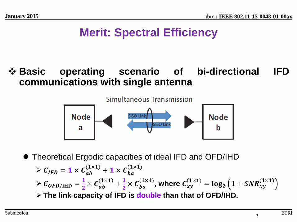
Merit: Spectral Efficiency
Basic operating scenario of bi-directional IFDcommunications with single antenna
Theoretical Ergodic capacities of ideal IFD and OFD/IHD
𝑪𝑰𝑭𝑫 = 𝟏 × 𝑪𝒂𝒃(𝟏×𝟏)
+ 𝟏 × 𝑪𝒃𝒂(𝟏×𝟏)
𝑪𝑶𝑭𝑫/𝐈𝐇𝐃 =𝟏
𝟐× 𝑪𝒂𝒃
(𝟏×𝟏)+
𝟏
𝟐× 𝑪𝒃𝒂
(𝟏×𝟏), where 𝑪𝒙𝒚
(𝟏×𝟏)= 𝐥𝐨𝐠𝟐 𝟏 + 𝑺𝑵𝑹𝒙𝒚
(𝟏×𝟏)
The link capacity of IFD is double than that of OFD/IHD.
6
doc.: IEEE 802.11-15-0043-01-00ax
Submission
January 2015
ETRI
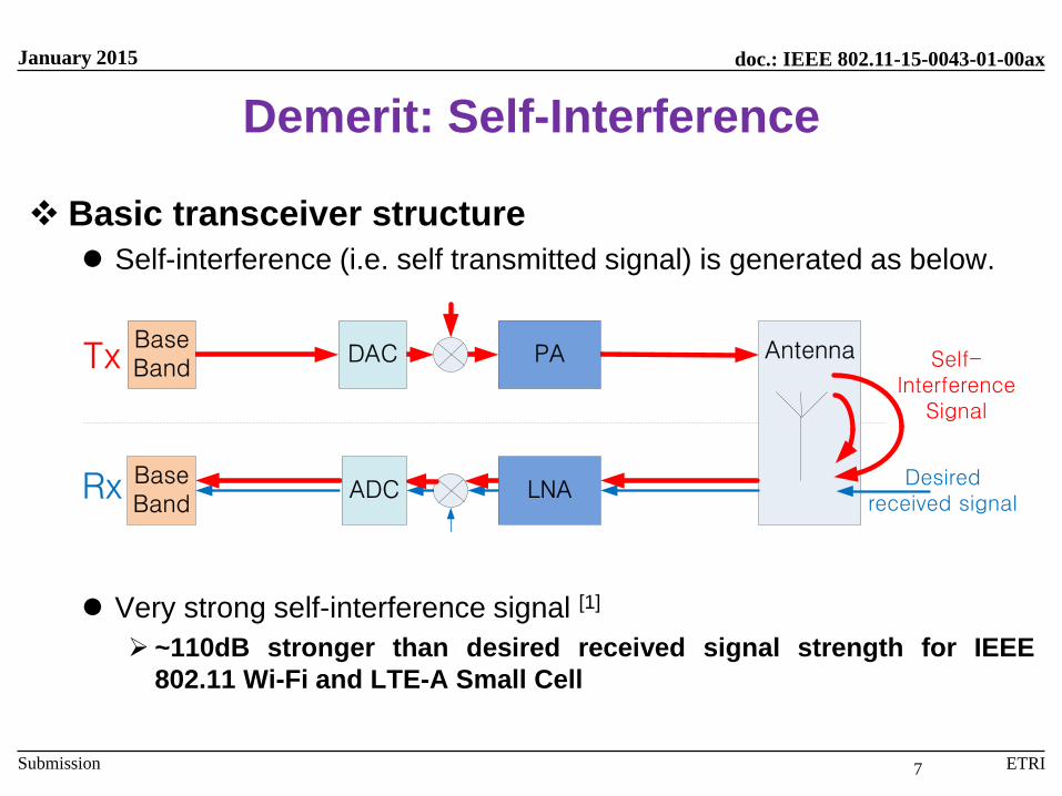
Demerit: Self-Interference
Basic transceiver structure
Self-interference (i.e. self transmitted signal) is generated as below.
Very strong self-interference signal [1]
~110dB stronger than desired received signal strength for IEEE
802.11 Wi-Fi and LTE-A Small Cell
AntennaTx
Rx Desired received signal
Self-Interference
Signal
ADCBaseBand
LNA
PADACBaseBand
7
doc.: IEEE 802.11-15-0043-01-00ax
Submission
January 2015
ETRI
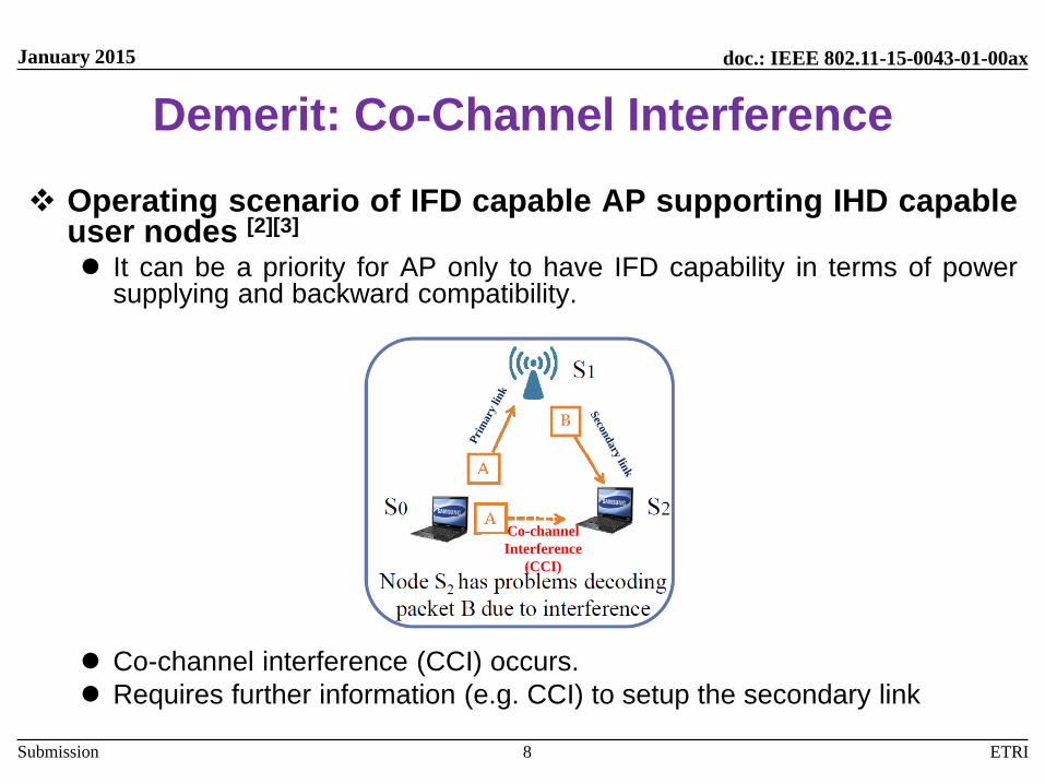
Demerit: Co-Channel Interference
Operating scenario of IFD capable AP supporting IHD capableuser nodes [2][3]
It can be a priority for AP only to have IFD capability in terms of powersupplying and backward compatibility.
Co-channel interference (CCI) occurs.
Requires further information (e.g. CCI) to setup the secondary link
8
Co-channel
Interference
(CCI)
Pri
mar
y link
Secon
dary lin
k
doc.: IEEE 802.11-15-0043-01-00ax
Submission
January 2015
ETRI
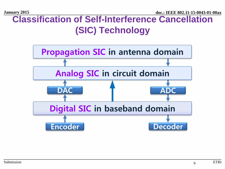
Classification of Self-Interference Cancellation
(SIC) Technology
9
Encoder Decoder
DAC ADC
Digital SIC in baseband domain
Analog SIC in circuit domain
Propagation SIC in antenna domain

doc.: IEEE 802.11-15-0043-01-00ax
Submission
January 2015
ETRI
Key Issues on SIC
Inefficiency of propagation SIC (PSIC)
Mainly using physical isolation between Tx and Rx antennas [4]
Any propagation SIC technologies are not recommended because
the merit of IFD in terms of spectral efficiency over OFD/IHD disappears
The form-factor size of IFD transceiver becomes larger.
Thus, single antenna is recommended to realize the merit of spectralefficiency
That is to say, no propagation SIC gain in antenna domain
Importance of analog SIC (ASIC)
Protecting analog-to-digital converter (ADC) saturation
Analog SIC technology is the crux of IFD commercialization.
Non-linear component in digital SIC (DSIC)
Dependent on surrounding environment of IFD transceiver, non-linearcomponent self-interference signal cannot be sufficiently cancelled inanalog domain. In this case, there is no successful decoding without thiscomponent cancellation.
10
doc.: IEEE 802.11-15-0043-01-00ax
Submission
January 2015
ETRI
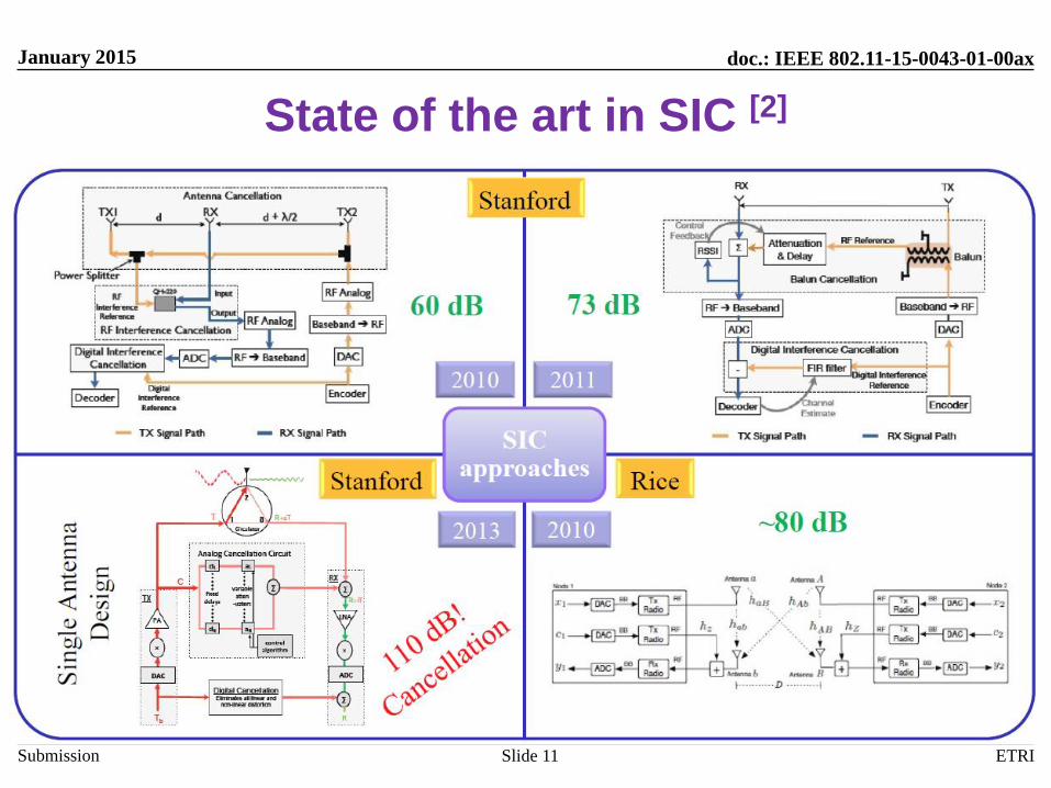
State of the art in SIC [2]
Slide 11
doc.: IEEE 802.11-15-0043-01-00ax
Submission
January 2015
ETRI
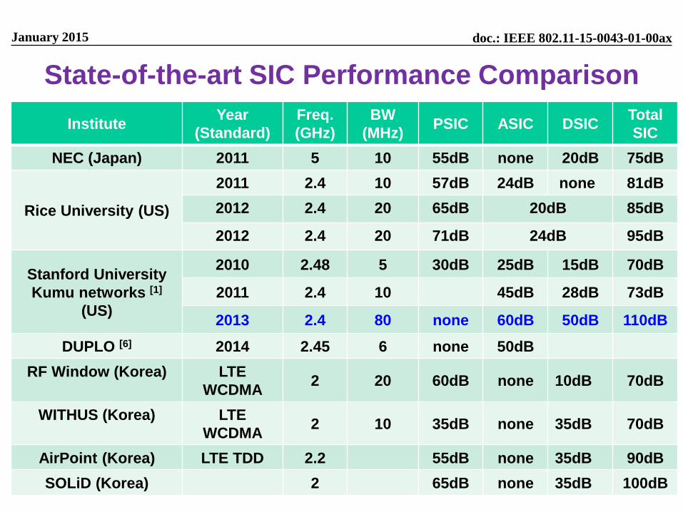
State-of-the-art SIC Performance Comparison
InstituteYear
(Standard)
Freq.
(GHz)
BW
(MHz)PSIC ASIC DSIC
Total
SIC
NEC (Japan) 2011 5 10 55dB none 20dB 75dB
Rice University (US)
2011 2.4 10 57dB 24dB none 81dB
2012 2.4 20 65dB 20dB 85dB
2012 2.4 20 71dB 24dB 95dB
Stanford University
Kumu networks [1]
(US)
2010 2.48 5 30dB 25dB 15dB 70dB
2011 2.4 10 45dB 28dB 73dB
2013 2.4 80 none 60dB 50dB 110dB
DUPLO [6] 2014 2.45 6 none 50dB
RF Window (Korea) LTE
WCDMA2 20 60dB none 10dB 70dB
WITHUS (Korea) LTE
WCDMA2 10 35dB none 35dB 70dB
AirPoint (Korea) LTE TDD 2.2 55dB none 35dB 90dB
SOLiD (Korea) 2 65dB none 35dB 100dB
doc.: IEEE 802.11-15-0043-01-00ax
Submission
January 2015
ETRI
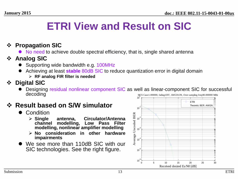
ETRI View and Result on SIC
Propagation SIC No need to achieve double spectral efficiency, that is, single shared antenna
Analog SIC Supporting wide bandwidth e.g. 100MHz
Achieving at least stable 80dB SIC to reduce quantization error in digital domain RF analog FIR filter is needed
Digital SIC Designing residual nonlinear component SIC as well as linear-component SIC for successful
decoding
13
0 5 10 15 20 25 3010
-6
10-5
10-4
10-3
10-2
10-1
100
Received desired Es/N0 [dB]
Av
era
ge U
nco
ded
BE
R
MCS Case:1.000000, fading:OFF, AWGN:ON, Over-sampling freq:80.000000 MHz
ETRI
Theoretic BER: AWGN Result based on S/W simulator Condition
Single antenna, Circulator/Antennachannel modelling, Low Pass Filtermodelling, nonlinear amplifier modelling
No consideration in other hardwareimpairments
We see more than 110dB SIC with ourSIC technologies. See the right figure.

doc.: IEEE 802.11-15-0043-01-00ax
Submission
January 2015
ETRI
System Performance
and Summary
Slide 14
doc.: IEEE 802.11-15-0043-01-00ax
Submission
January 2015
ETRI
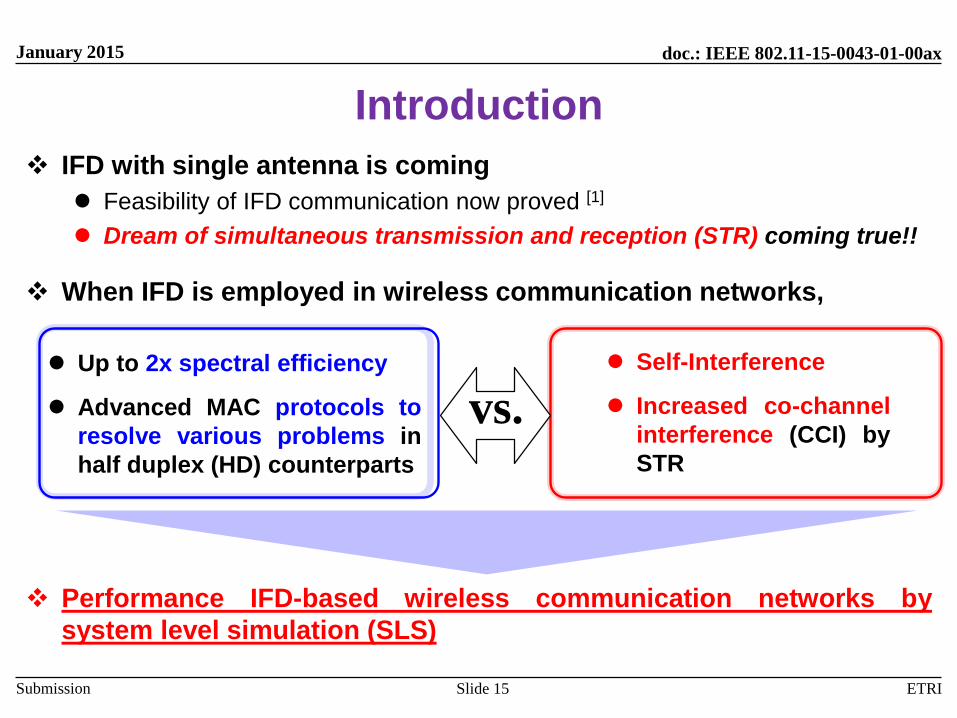
Introduction
IFD with single antenna is coming
Feasibility of IFD communication now proved [1]
Dream of simultaneous transmission and reception (STR) coming true!!
When IFD is employed in wireless communication networks,
Performance IFD-based wireless communication networks by
system level simulation (SLS)
Slide 15
Up to 2x spectral efficiency
Advanced MAC protocols to
resolve various problems in
half duplex (HD) counterparts
Self-Interference
Increased co-channel
interference (CCI) by
STR
vs.

doc.: IEEE 802.11-15-0043-01-00ax
Submission
January 2015
ETRI
Duplex Mode – TDD
Slide 16
AP2AP2
AP1AP1
: Desired Signal : Co-Channel Interference (CCI)
DL mode
STA1
STA2
STA3
STA4
AP2AP2
AP1AP1
: Desired Signal : Co-Channel Interference (CCI)
UL mode
STA1
STA2
STA3
STA4
doc.: IEEE 802.11-15-0043-01-00ax
Submission
January 2015
ETRI
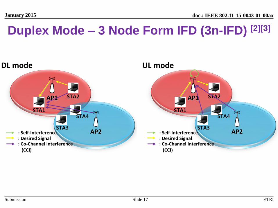
Duplex Mode – 3 Node Form IFD (3n-IFD) [2][3]
Slide 17
AP2AP2
AP1AP1
: Desired Signal : Co-Channel Interference (CCI)
DL mode
STA1
STA2
STA3
STA4
: Self-Interference AP2AP2
AP1AP1
: Desired Signal : Co-Channel Interference (CCI)
UL mode
STA1
STA2
STA3
STA4
: Self-Interference
doc.: IEEE 802.11-15-0043-01-00ax
Submission
January 2015
ETRI
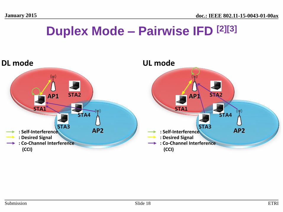
Duplex Mode – Pairwise IFD [2][3]
Slide 18
AP2AP2
AP1AP1
: Desired Signal : Co-Channel Interference (CCI)
DL mode
STA1
STA2
STA3
STA4
: Self-Interference AP2AP2
AP1AP1
: Desired Signal : Co-Channel Interference (CCI)
UL mode
STA1
STA2
STA3
STA4
: Self-Interference
doc.: IEEE 802.11-15-0043-01-00ax
Submission
January 2015
ETRI
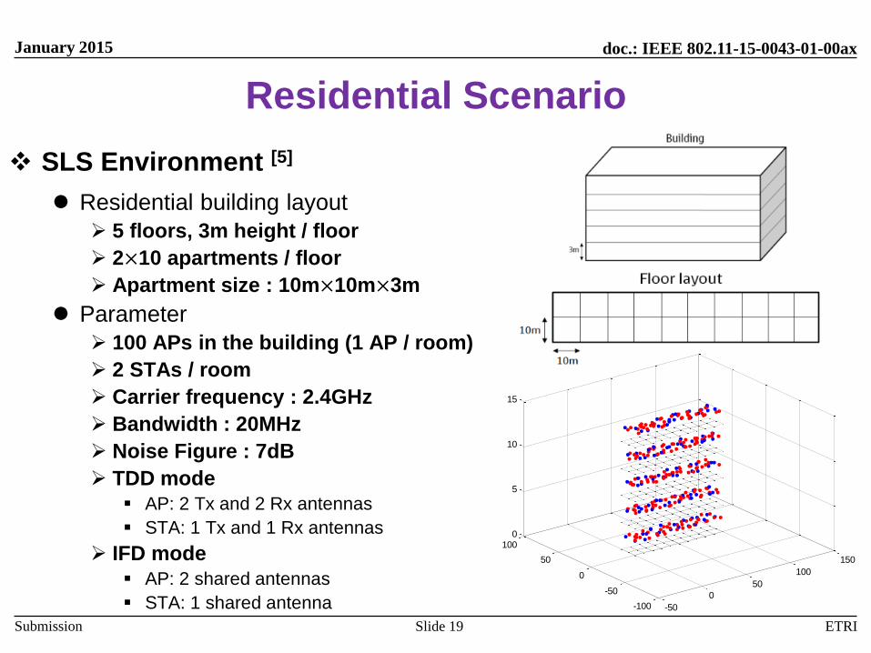
Residential Scenario
SLS Environment [5]
Residential building layout
5 floors, 3m height / floor
2×10 apartments / floor
Apartment size : 10m×10m×3m
Parameter
100 APs in the building (1 AP / room)
2 STAs / room
Carrier frequency : 2.4GHz
Bandwidth : 20MHz
Noise Figure : 7dB
TDD mode
AP: 2 Tx and 2 Rx antennas
STA: 1 Tx and 1 Rx antennas
IFD mode
AP: 2 shared antennas
STA: 1 shared antenna
Slide 19
-50
0
50
100
150
-100
-50
0
50
1000
5
10
15
doc.: IEEE 802.11-15-0043-01-00ax
Submission
January 2015
ETRI
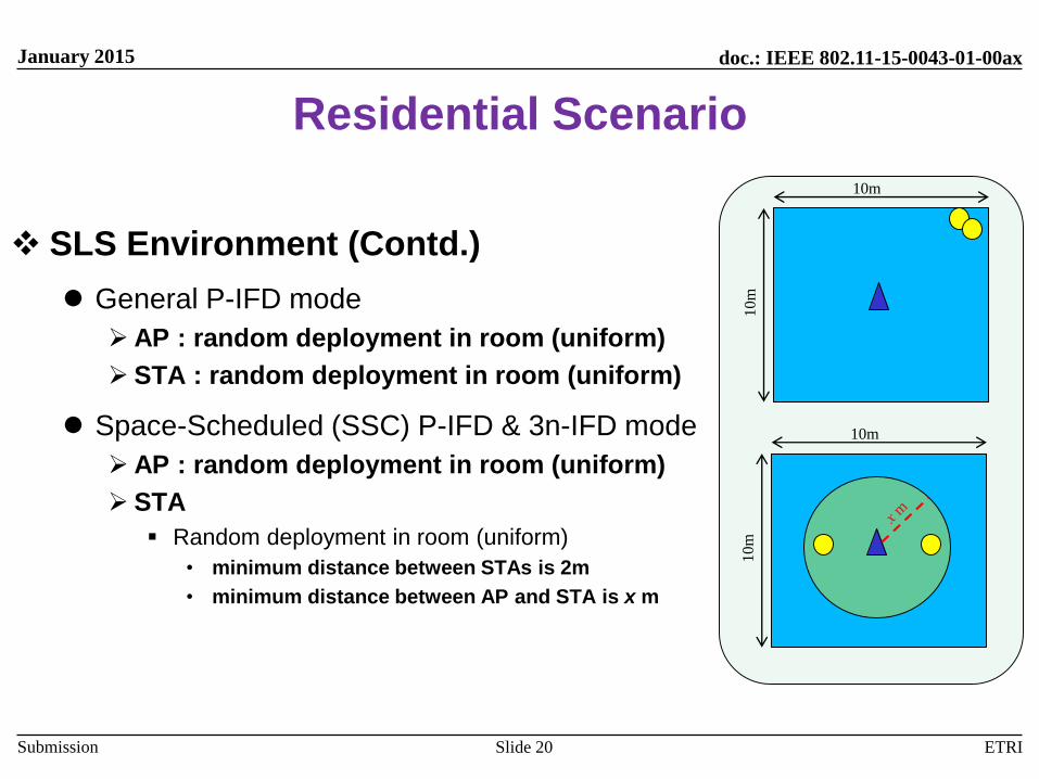
Residential Scenario
SLS Environment (Contd.)
General P-IFD mode
AP : random deployment in room (uniform)
STA : random deployment in room (uniform)
Space-Scheduled (SSC) P-IFD & 3n-IFD mode
AP : random deployment in room (uniform)
STA
Random deployment in room (uniform)
• minimum distance between STAs is 2m
• minimum distance between AP and STA is x m
Slide 20
10m
10m
10
m
10m
doc.: IEEE 802.11-15-0043-01-00ax
Submission
January 2015
ETRI
-20 -10 0 10 20 30 400
0.1
0.2
0.3
0.4
0.5
0.6
0.7
0.8
0.9
1
SINR
CD
F
Downlink SINR
P-IFD, general(120dB)
P-IFD, general(80dB)
P-IFD, general(70dB)
P-IFD, general(50dB)
P-IFD, SSC(120dB)
P-IFD, SSC(80dB)
P-IFD, SSC(70dB)
P-IFD, SSC(50dB)
-20 -10 0 10 20 30 400
0.1
0.2
0.3
0.4
0.5
0.6
0.7
0.8
0.9
1
SINR
CD
F
UPlink SINR
P-IFD, general(120dB)
P-IFD, general(80dB)
P-IFD, general(70dB)
P-IFD, general(50dB)
P-IFD, SSC(120dB)
P-IFD, SSC(80dB)
P-IFD, SSC(70dB)
P-IFD, SSC(50dB)
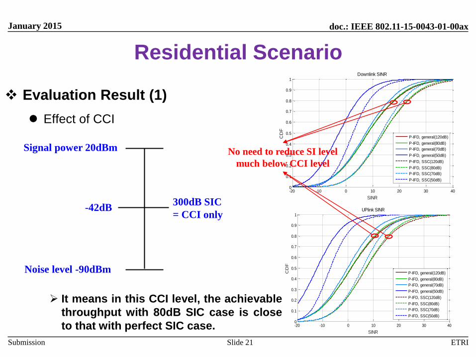
Residential Scenario
Evaluation Result (1)
Effect of CCI
It means in this CCI level, the achievable
throughput with 80dB SIC case is close
to that with perfect SIC case.
Slide 21
Noise level -90dBm
Signal power 20dBm
300dB SIC
= CCI only-42dB
No need to reduce SI level
much below CCI level
doc.: IEEE 802.11-15-0043-01-00ax
Submission
January 2015
ETRI
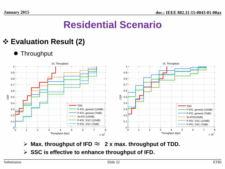
Residential Scenario
Evaluation Result (2)
Throughput
Max. throughput of IFD 2 x max. throughput of TDD.
SSC is effective to enhance throughput of IFD.
Slide 22
0 1 2 3 4 5 6 7 8
x 107
0
0.1
0.2
0.3
0.4
0.5
0.6
0.7
0.8
0.9
1
Throughput (bps)
CD
F
DL Throughput
TDD
P-IFD, general (120dB)
P-IFD, general (70dB)
3n-IFD (120dB)
P-IFD, SSC (120dB)
P-IFD, SSC (70dB)
0 1 2 3 4 5 6 7 8
x 107
0
0.1
0.2
0.3
0.4
0.5
0.6
0.7
0.8
0.9
1
Throughput (bps)
CD
F
UL Throughput
TDD
P-IFD, general (120dB)
P-IFD, general (70dB)
3n-IFD(120dB)
P-IFD, SSC (120dB)
P-IFD, SSC (70dB)
≈

doc.: IEEE 802.11-15-0043-01-00ax
Submission
January 2015
ETRI
Residential Scenario
Evaluation Result (3)
Areal Throughput
50% enhancement of areal throughput by 3n-IFD with sufficient SIC
300% enhancement of areal throughput by P-IFD with sufficient SIC
Noticeable areal throughput enhancement by SSCSlide 23
1 1.5 2 2.5 3 3.5 4 4.5 50
1
2
3
4
5
6x 10
10 DL Areal Throughput
# of cumulated floors
Are
al th
rou
gh
pu
t (b
ps)
P-IFD, general (120dB)
P-IFD, general (80dB)
P-IFD, general (70dB)
P-IFD, general (50dB)
P-IFD, SSC (120dB)
P-IFD, SSC (80dB)
P-IFD, SSC (70dB)
P-IFD, SSC (50dB)
3n-IFD (120dB)
TDD
1 1.5 2 2.5 3 3.5 4 4.5 50
0.5
1
1.5
2
2.5
3
3.5
4
4.5
5x 10
10 UL Areal Throughput
# of cumulated floors
Are
al th
rou
gh
pu
t (b
ps)
P-IFD, general (120dB)
P-IFD, general (80dB)
P-IFD, general (70dB)
P-IFD, general (50dB)
P-IFD, SSC (120dB)
P-IFD, SSC (80dB)
P-IFD, SSC (70dB)
P-IFD, SSC (50dB)
3n-IFD (120dB)
TDD
doc.: IEEE 802.11-15-0043-01-00ax
Submission
January 2015
ETRI
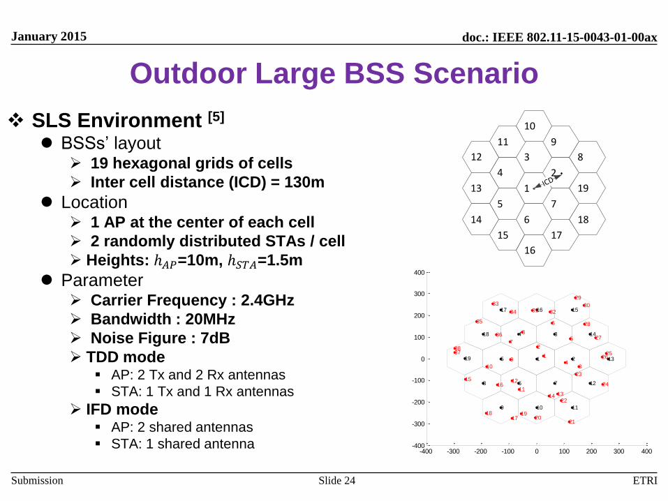
Outdoor Large BSS Scenario
SLS Environment [5]
BSSs’ layout 19 hexagonal grids of cells
Inter cell distance (ICD) = 130m
Location 1 AP at the center of each cell
2 randomly distributed STAs / cell
Heights: ℎ𝐴𝑃=10m, ℎ𝑆𝑇𝐴=1.5m
Parameter Carrier Frequency : 2.4GHz
Bandwidth : 20MHz
Noise Figure : 7dB
TDD mode AP: 2 Tx and 2 Rx antennas
STA: 1 Tx and 1 Rx antennas
IFD mode AP: 2 shared antennas
STA: 1 shared antenna
Slide 24
-400 -300 -200 -100 0 100 200 300 400-400
-300
-200
-100
0
100
200
300
400
1 2
34
5
6 78
9 10 11
12
13
14
151617
18
19 1
2
34
5
6
7
8
9
10
11
12
1314
1516
1718 19
2021
22
23
24
2526
27
28
29
3031 32
33
34
35
36
3738
1
3
2ICD
6
7
4
5
8
9
12
13
14
15 17
18
19
16
11
10
doc.: IEEE 802.11-15-0043-01-00ax
Submission
January 2015
ETRI
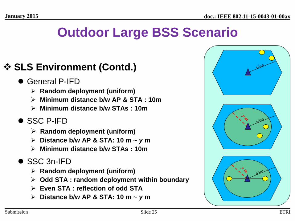
Outdoor Large BSS Scenario
SLS Environment (Contd.)
General P-IFD Random deployment (uniform)
Minimum distance b/w AP & STA : 10m
Minimum distance b/w STAs : 10m
SSC P-IFD
Random deployment (uniform)
Distance b/w AP & STA: 10 m ~ y m
Minimum distance b/w STAs : 10m
SSC 3n-IFD Random deployment (uniform)
Odd STA : random deployment within boundary
Even STA : reflection of odd STA
Distance b/w AP & STA: 10 m ~ y m
Slide 25
doc.: IEEE 802.11-15-0043-01-00ax
Submission
January 2015
ETRI
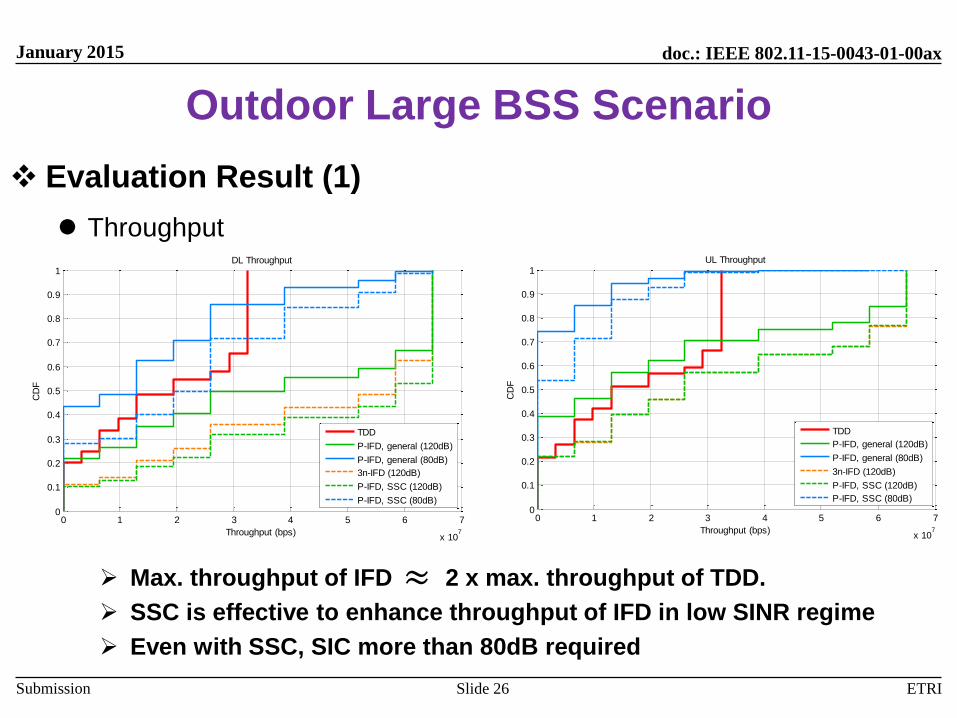
Outdoor Large BSS Scenario
Evaluation Result (1)
Throughput
Max. throughput of IFD 2 x max. throughput of TDD.
SSC is effective to enhance throughput of IFD in low SINR regime
Even with SSC, SIC more than 80dB required
Slide 26
0 1 2 3 4 5 6 7
x 107
0
0.1
0.2
0.3
0.4
0.5
0.6
0.7
0.8
0.9
1
Throughput (bps)
CD
F
DL Throughput
TDD
P-IFD, general (120dB)
P-IFD, general (80dB)
3n-IFD (120dB)
P-IFD, SSC (120dB)
P-IFD, SSC (80dB)
0 1 2 3 4 5 6 7
x 107
0
0.1
0.2
0.3
0.4
0.5
0.6
0.7
0.8
0.9
1
Throughput (bps)
CD
F
UL Throughput
TDD
P-IFD, general (120dB)
P-IFD, general (80dB)
3n-IFD (120dB)
P-IFD, SSC (120dB)
P-IFD, SSC (80dB)
≈
doc.: IEEE 802.11-15-0043-01-00ax
Submission
January 2015
ETRI
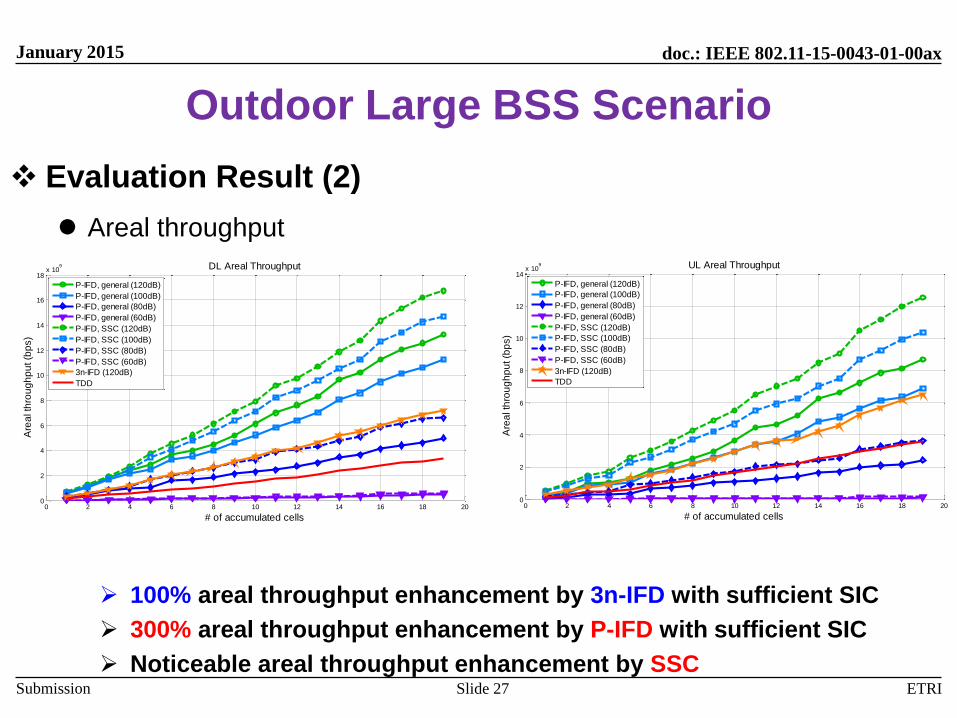
Outdoor Large BSS Scenario
Evaluation Result (2)
Areal throughput
100% areal throughput enhancement by 3n-IFD with sufficient SIC
300% areal throughput enhancement by P-IFD with sufficient SIC
Noticeable areal throughput enhancement by SSCSlide 27
0 2 4 6 8 10 12 14 16 18 200
2
4
6
8
10
12
14
16
18x 10
9 DL Areal Throughput
# of accumulated cells
Are
al th
rou
gh
pu
t (b
ps)
P-IFD, general (120dB)
P-IFD, general (100dB)
P-IFD, general (80dB)
P-IFD, general (60dB)
P-IFD, SSC (120dB)
P-IFD, SSC (100dB)
P-IFD, SSC (80dB)
P-IFD, SSC (60dB)
3n-IFD (120dB)
TDD
0 2 4 6 8 10 12 14 16 18 200
2
4
6
8
10
12
14x 10
9 UL Areal Throughput
# of accumulated cellsA
rea
l th
rou
gh
pu
t (b
ps)
P-IFD, general (120dB)
P-IFD, general (100dB)
P-IFD, general (80dB)
P-IFD, general (60dB)
P-IFD, SSC (120dB)
P-IFD, SSC (100dB)
P-IFD, SSC (80dB)
P-IFD, SSC (60dB)
3n-IFD (120dB)
TDD

doc.: IEEE 802.11-15-0043-01-00ax
Submission
January 2015
ETRI
Summary
Simultaneous transmission and reception is coming.
When deployed in Wi-Fi networks, the system throughput with 80dB SICcase approached that with perfect SIC case (indoors).
When STA density is low, extra SIC performance can further enhance thesystem throughput (outdoors).
System level simulations show that with sufficient SIC performance, IFDleads to severalfold throughput enhancements compared to conventionalhalf duplex counterpart.
(Spatial) scheduling plays a key role to enhance performance of IFD-based Wi-Fi networks.
If 4 times areal throughput enhancement is desired, adopting IFD is oneof answers.
Slide 28

doc.: IEEE 802.11-15-0043-01-00ax
Submission
January 2015
ETRISlide 29
References
1. IEEE 802.11-13/1421r1, “STR radios and STR media access.”
2. IEEE 802.11-13/1122r1, “Considerations for In-Band Simultaneous
Transmit and Receive (STR) Feature in Hew”
3. IEEE 802.11-14/0838r0, “Discussion on Dual-Link STR in IEEE
802.11 ax”
4. E. Everett, A. Sahai, and A. Sabharwal, “Passive self-interference
suppression for full-duplex infrastructure nodes,” IEEE Trans. Wireless
Commun., vol. 13, no. 2, pp. 680-694, Feb. 2014.
5. IEEE 802.11-14/0980r4, “TGax Simulation Scenarios.”
6. DUPLO, ‘D4.1.1-Performance of full-duplex systems,’ http://www.fp7-
duplo.eu/index.php/.
doc.: IEEE 802.11-15-0043-01-00ax
Submission
January 2015
ETRI
Appendix
Slide 30
doc.: IEEE 802.11-15-0043-01-00ax
Submission
January 2015
ETRI
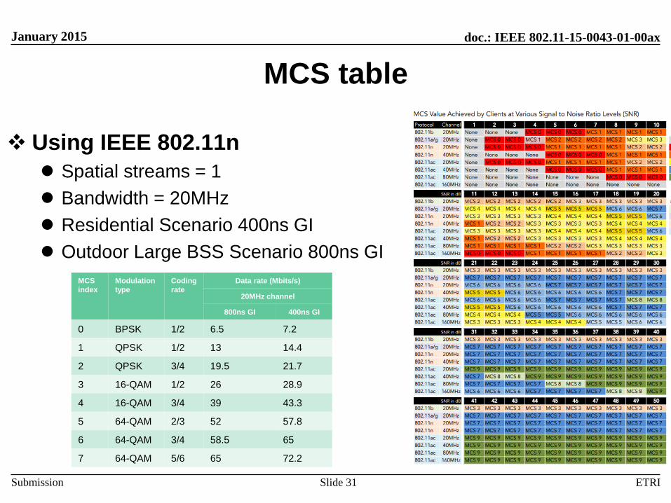
MCS table
Using IEEE 802.11n
Spatial streams = 1
Bandwidth = 20MHz
Residential Scenario 400ns GI
Outdoor Large BSS Scenario 800ns GI
Slide 31
MCS
index
Modulation
type
Coding
rate
Data rate (Mbits/s)
20MHz channel
800ns GI 400ns GI
0 BPSK 1/2 6.5 7.2
1 QPSK 1/2 13 14.4
2 QPSK 3/4 19.5 21.7
3 16-QAM 1/2 26 28.9
4 16-QAM 3/4 39 43.3
5 64-QAM 2/3 52 57.8
6 64-QAM 3/4 58.5 65
7 64-QAM 5/6 65 72.2

doc.: IEEE 802.11-15-0043-01-00ax
Submission
January 2015
ETRI
Residential Scenario
Other Simulation Results (2) SINR
DL
with 120 dB SIC, the SINR of pairwise IFD ≈ TDD
5 dB gain with SSC
UL
Increase of CCI between APs,
Both IFD schemes show inferior performance to TDD even with 120 dB SICSlide 32
-20 -10 0 10 20 30 400
0.1
0.2
0.3
0.4
0.5
0.6
0.7
0.8
0.9
1
SINR
CD
F
DL SINR
TDD
Pairwise IFD1(120dB)
Pairwise IFD1(70dB)
3 node form IFD(120dB)
Pairwise IFD2(70dB)
Pairwise IFD2(120dB)
-20 -10 0 10 20 30 400
0.1
0.2
0.3
0.4
0.5
0.6
0.7
0.8
0.9
1
SINRC
DF
UL SINR
TDD
Pairwise IFD1(120dB)
Pairwise IFD1(70dB)
3 node form IFD(120dB)
Pairwise IFD2(120dB)
Pairwise IFD2(70dB)
doc.: IEEE 802.11-15-0043-01-00ax
Submission
January 2015
ETRI
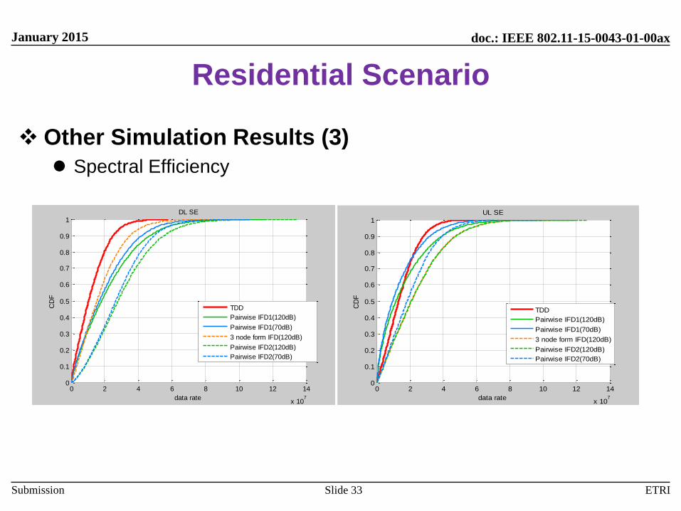
Residential Scenario
Other Simulation Results (3)
Spectral Efficiency
Slide 33
0 2 4 6 8 10 12 14
x 107
0
0.1
0.2
0.3
0.4
0.5
0.6
0.7
0.8
0.9
1
data rate
CD
F
DL SE
TDD
Pairwise IFD1(120dB)
Pairwise IFD1(70dB)
3 node form IFD(120dB)
Pairwise IFD2(120dB)
Pairwise IFD2(70dB)
0 2 4 6 8 10 12 14
x 107
0
0.1
0.2
0.3
0.4
0.5
0.6
0.7
0.8
0.9
1
data rate
CD
F
UL SE
TDD
Pairwise IFD1(120dB)
Pairwise IFD1(70dB)
3 node form IFD(120dB)
Pairwise IFD2(120dB)
Pairwise IFD2(70dB)
doc.: IEEE 802.11-15-0043-01-00ax
Submission
January 2015
ETRI
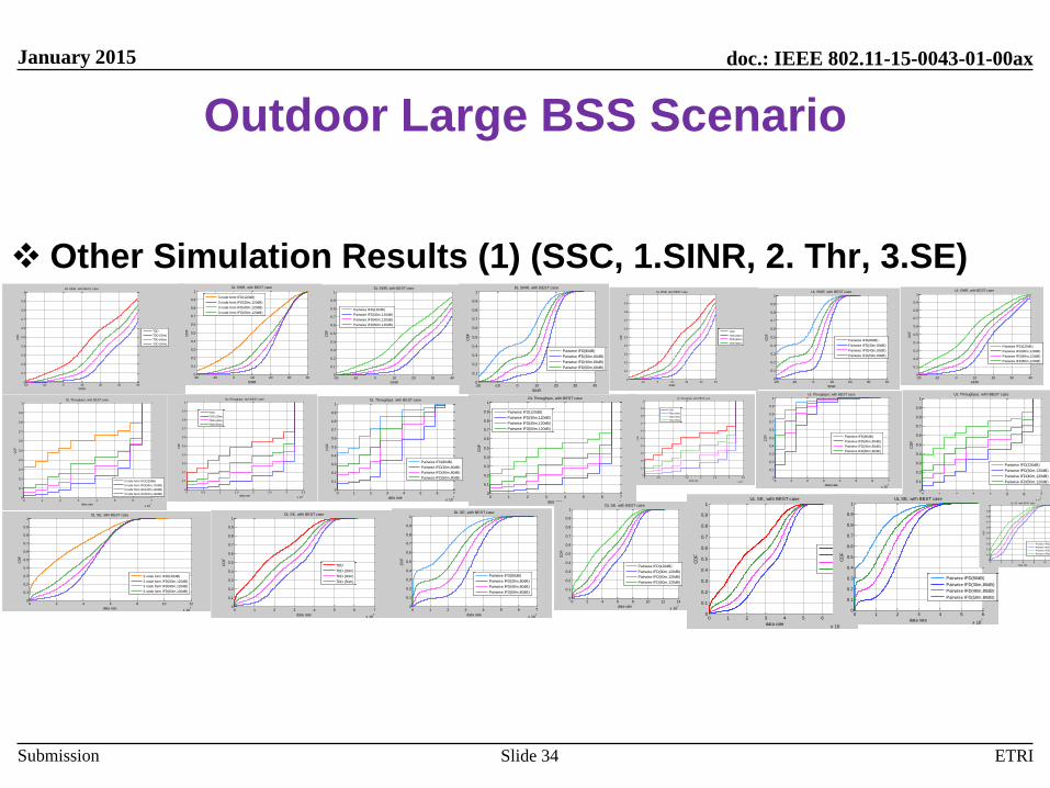
Outdoor Large BSS Scenario
Other Simulation Results (1) (SSC, 1.SINR, 2. Thr, 3.SE)
Slide 34
-20 -10 0 10 20 30 400
0.1
0.2
0.3
0.4
0.5
0.6
0.7
0.8
0.9
1
SINR
CD
F
DL SINR, with BEST case
TDD
TDD (30m)
TDD (40m)
TDD (50m)
-20 -10 0 10 20 30 400
0.1
0.2
0.3
0.4
0.5
0.6
0.7
0.8
0.9
1
SINR
CD
F
DL SINR, with BEST case
3 node form IFD(120dB)
3 node form IFD(30m,120dB)
3 node form IFD(40m,120dB)
3 node form IFD(50m,120dB)
-20 -10 0 10 20 30 400
0.1
0.2
0.3
0.4
0.5
0.6
0.7
0.8
0.9
1
SINR
CD
F
DL SINR, with BEST case
Pairwise IFD(120dB)
Pairwise IFD(30m,120dB)
Pairwise IFD(40m,120dB)
Pairwise IFD(50m,120dB)
-20 -10 0 10 20 30 400
0.1
0.2
0.3
0.4
0.5
0.6
0.7
0.8
0.9
1
SINR
CD
F
DL SINR, with BEST case
Pairwise IFD(80dB)
Pairwise IFD(30m,80dB)
Pairwise IFD(40m,80dB)
Pairwise IFD(50m,80dB)
-10 0 10 20 30 400
0.1
0.2
0.3
0.4
0.5
0.6
0.7
0.8
0.9
1
SINR
CD
F
UL SINR, with BEST case
TDD
TDD (30m)
TDD (40m)
TDD (50m)
-20 -10 0 10 20 30 400
0.1
0.2
0.3
0.4
0.5
0.6
0.7
0.8
0.9
1
SINR
CD
F
UL SINR, with BEST case
Pairwise IFD(80dB)
Pairwise IFD(30m,80dB)
Pairwise IFD(40m,80dB)
Pairwise IFD(50m,80dB)
-20 -10 0 10 20 30 400
0.1
0.2
0.3
0.4
0.5
0.6
0.7
0.8
0.9
1
SINR
CD
F
UL SINR, with BEST case
Pairwise IFD(120dB)
Pairwise IFD(30m,120dB)
Pairwise IFD(40m,120dB)
Pairwise IFD(50m,120dB)
0 1 2 3 4 5 6 7
x 107
0
0.1
0.2
0.3
0.4
0.5
0.6
0.7
0.8
0.9
1
data rate
CD
F
DL Throughput, with BEST case
3 node form IFD(120dB)
3 node form IFD(30m,120dB)
3 node form IFD(40m,120dB)
3 node form IFD(50m,120dB)0 0.5 1 1.5 2 2.5 3 3.5
x 107
0
0.1
0.2
0.3
0.4
0.5
0.6
0.7
0.8
0.9
1
data rate
CD
F
DL Throughput, with BEST case
TDD
TDD (30m)
TDD (40m)
TDD (50m)
0 1 2 3 4 5 6 7
x 107
0
0.1
0.2
0.3
0.4
0.5
0.6
0.7
0.8
0.9
1
data rate
CD
F
DL Throughput, with BEST case
Pairwise IFD(80dB)
Pairwise IFD(30m,80dB)
Pairwise IFD(40m,80dB)
Pairwise IFD(50m,80dB)
0 1 2 3 4 5 6 7
x 107
0
0.1
0.2
0.3
0.4
0.5
0.6
0.7
0.8
0.9
1
data rate
CD
F
DL Throughput, with BEST case
Pairwise IFD(120dB)
Pairwise IFD(30m,120dB)
Pairwise IFD(40m,120dB)
Pairwise IFD(50m,120dB)
0 0.5 1 1.5 2 2.5 3 3.5
x 107
0
0.1
0.2
0.3
0.4
0.5
0.6
0.7
0.8
0.9
1
data rate
CD
F
UL Throughput, with BEST case
TDD
TDD (30m)
TDD (30m)
TDD (30m)
0 1 2 3 4 5 6 7
x 107
0
0.1
0.2
0.3
0.4
0.5
0.6
0.7
0.8
0.9
1
data rate
CD
F
UL Throughput, with BEST case
Pairwise IFD(80dB)
Pairwise IFD(30m,80dB)
Pairwise IFD(40m,80dB)
Pairwise IFD(50m,80dB)
0 1 2 3 4 5 6 7
x 107
0
0.1
0.2
0.3
0.4
0.5
0.6
0.7
0.8
0.9
1
data rate
CD
F
UL Throughput, with BEST case
Pairwise IFD(120dB)
Pairwise IFD(30m,120dB)
Pairwise IFD(40m,120dB)
Pairwise IFD(50m,120dB)
0 2 4 6 8 10 12
x 107
0
0.1
0.2
0.3
0.4
0.5
0.6
0.7
0.8
0.9
1
data rate
CD
F
DL SE, with BEST case
3 node form IFD(120dB)
3 node form IFD(30m,120dB)
3 node form IFD(40m,120dB)
3 node form IFD(50m,120dB)
0 1 2 3 4 5 6 7
x 107
0
0.1
0.2
0.3
0.4
0.5
0.6
0.7
0.8
0.9
1
data rate
CD
F
DL SE, with BEST case
TDD
TDD (30m)
TDD (40m)
TDD (50m)
0 1 2 3 4 5 6 7
x 107
0
0.1
0.2
0.3
0.4
0.5
0.6
0.7
0.8
0.9
1
data rate
CD
F
DL SE, with BEST case
Pairwise IFD(80dB)
Pairwise IFD(30m,80dB)
Pairwise IFD(40m,80dB)
Pairwise IFD(50m,80dB)
0 2 4 6 8 10 12 14
x 107
0
0.1
0.2
0.3
0.4
0.5
0.6
0.7
0.8
0.9
1
data rate
CD
F
DL SE, with BEST case
Pairwise IFD(120dB)
Pairwise IFD(30m,120dB)
Pairwise IFD(40m,120dB)
Pairwise IFD(50m,120dB)
0 1 2 3 4 5 6 7
x 107
0
0.1
0.2
0.3
0.4
0.5
0.6
0.7
0.8
0.9
1
data rate
CD
F
UL SE, with BEST case
TDD
TDD(30m)
TDD(40m)
TDD(50m)
0 1 2 3 4 5 6
x 107
0
0.1
0.2
0.3
0.4
0.5
0.6
0.7
0.8
0.9
1
data rate
CD
F
UL SE, with BEST case
Pairwise IFD(80dB)
Pairwise IFD(30m,80dB)
Pairwise IFD(40m,80dB)
Pairwise IFD(50m,80dB)
0 2 4 6 8 10 12
x 107
0
0.1
0.2
0.3
0.4
0.5
0.6
0.7
0.8
0.9
1
data rate
CD
F
UL SE, with BEST case
Pairwise IFD(120dB)
Pairwise IFD(30m,120dB)
Pairwise IFD(40m,120dB)
Pairwise IFD(50m,120dB)
doc.: IEEE 802.11-15-0043-01-00ax
Submission
January 2015
ETRI
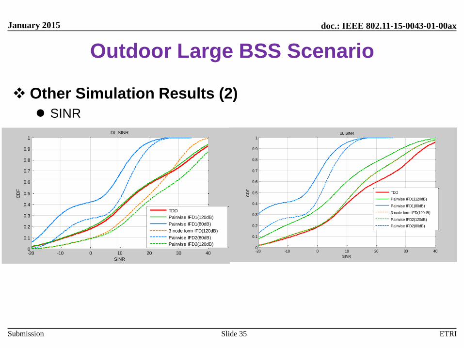
Outdoor Large BSS Scenario
Other Simulation Results (2)
SINR
Slide 35
-20 -10 0 10 20 30 400
0.1
0.2
0.3
0.4
0.5
0.6
0.7
0.8
0.9
1
SINR
CD
F
DL SINR
TDD
Pairwise IFD1(120dB)
Pairwise IFD1(80dB)
3 node form IFD(120dB)
Pairwise IFD2(80dB)
Pairwise IFD2(120dB)
-20 -10 0 10 20 30 400
0.1
0.2
0.3
0.4
0.5
0.6
0.7
0.8
0.9
1
SINR
CD
F
UL SINR
TDD
Pairwise IFD1(120dB)
Pairwise IFD1(80dB)
3 node form IFD(120dB)
Pairwise IFD2(120dB)
Pairwise IFD2(80dB)
doc.: IEEE 802.11-15-0043-01-00ax
Submission
January 2015
ETRI
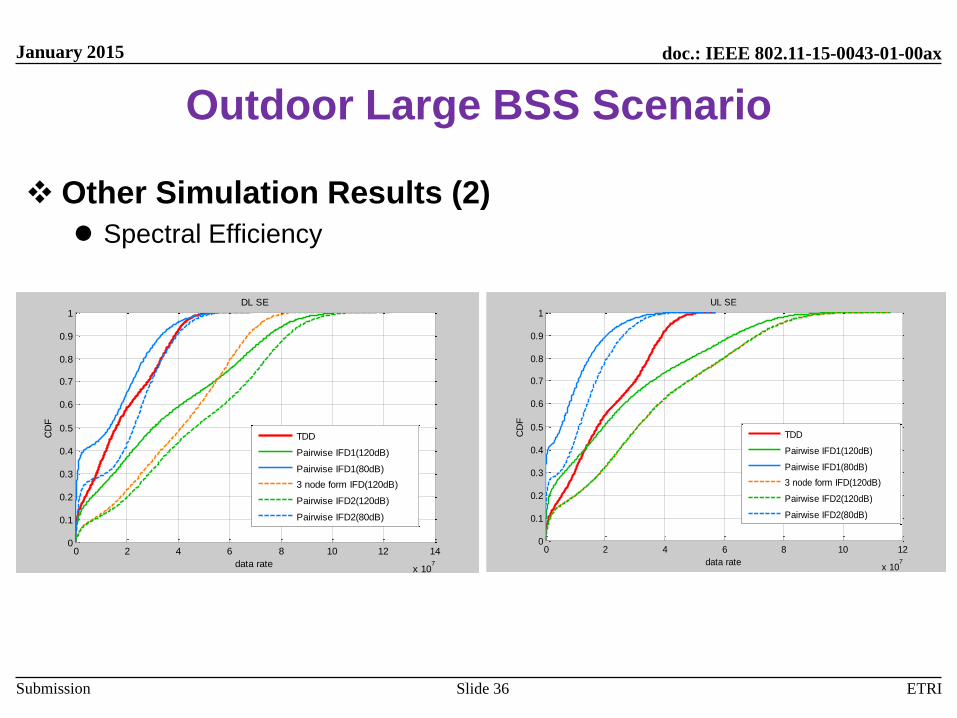
Outdoor Large BSS Scenario
Other Simulation Results (2)
Spectral Efficiency
Slide 36
0 2 4 6 8 10 12 14
x 107
0
0.1
0.2
0.3
0.4
0.5
0.6
0.7
0.8
0.9
1
data rate
CD
F
DL SE
TDD
Pairwise IFD1(120dB)
Pairwise IFD1(80dB)
3 node form IFD(120dB)
Pairwise IFD2(120dB)
Pairwise IFD2(80dB)
0 2 4 6 8 10 12
x 107
0
0.1
0.2
0.3
0.4
0.5
0.6
0.7
0.8
0.9
1
data rate
CD
F
UL SE
TDD
Pairwise IFD1(120dB)
Pairwise IFD1(80dB)
3 node form IFD(120dB)
Pairwise IFD2(120dB)
Pairwise IFD2(80dB)