Embed Size (px)
Citation preview

YORK® SIDEWALL ACTIVE CHILLED BEAMS
ENGINEERING GUIDE

2Johnson Controls
YORK® Sidewall Active Chilled Beams 3
CB-ABW-YK Performance Data 5
CB-ABW-YK Dimensions 10
Specifications 11
Contents
3Johnson Controls
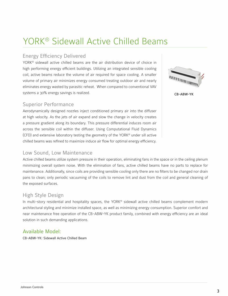
EnergyEfficiencyDeliveredYORK® sidewall active chilled beams are the air distribution device of choice in
high performing energy efficient buildings. Utilizing an integrated sensible cooling
coil, active beams reduce the volume of air required for space cooling. A smaller
volume of primary air minimizes energy consumed treating outdoor air and nearly
eliminates energy wasted by parasitic reheat. When compared to conventional VAV
systems a 30% energy savings is realized.
Superior PerformanceAerodynamically designed nozzles inject conditioned primary air into the diffuser
at high velocity. As the jets of air expand and slow the change in velocity creates
a pressure gradient along its boundary. This pressure differential induces room air
across the sensible coil within the diffuser. Using Computational Fluid Dynamics
(CFD) and extensive laboratory testing the geometry of the YORK® under sill active
chilled beams was refined to maximize induce air flow for optimal energy efficiency.
Low Sound, Low Maintenance Active chilled beams utilize system pressure in their operation, eliminating fans in the space or in the ceiling plenum
minimizing overall system noise. With the elimination of fans, active chilled beams have no parts to replace for
maintenance. Additionally, since coils are providing sensible cooling only there are no filters to be changed nor drain
pans to clean; only periodic vacuuming of the coils to remove lint and dust from the coil and general cleaning of
the exposed surfaces.
High Style Design In multi-story residential and hospitality spaces, the YORK® sidewall active chilled beams complement modern
architectural styling and minimize installed space, as well as minimizing energy consumption. Superior comfort and
near maintenance free operation of the CB-ABW-YK product family, combined with energy efficiency are an ideal
solution in such demanding applications.
Available Model:CB-ABW-YK: Sidewall Active Chilled Beam
YORK® Sidewall Active Chilled Beams
CB-ABW-YK

4Johnson Controls
Standard Features:• 2 foot to 10 foot lengths, 1 foot increments
• 2-pipe and 4-pipe coil configurations
• Configured nozzle geometry for capacity optimization
• Commissioning port with roomside access for balancing
• ½” Sweat water coil connections
• Coil air vent
• Perforated grille
Options and Accessories:• Linear bar grille
• ½” thick foil-faced EcoShield, anti-microbial external insulation
• Coil drain valve
• ½” MNPT water coil connections
• 12-inch, 18-inch or 24-inch stainless steel braided hoses
5Johnson Controls
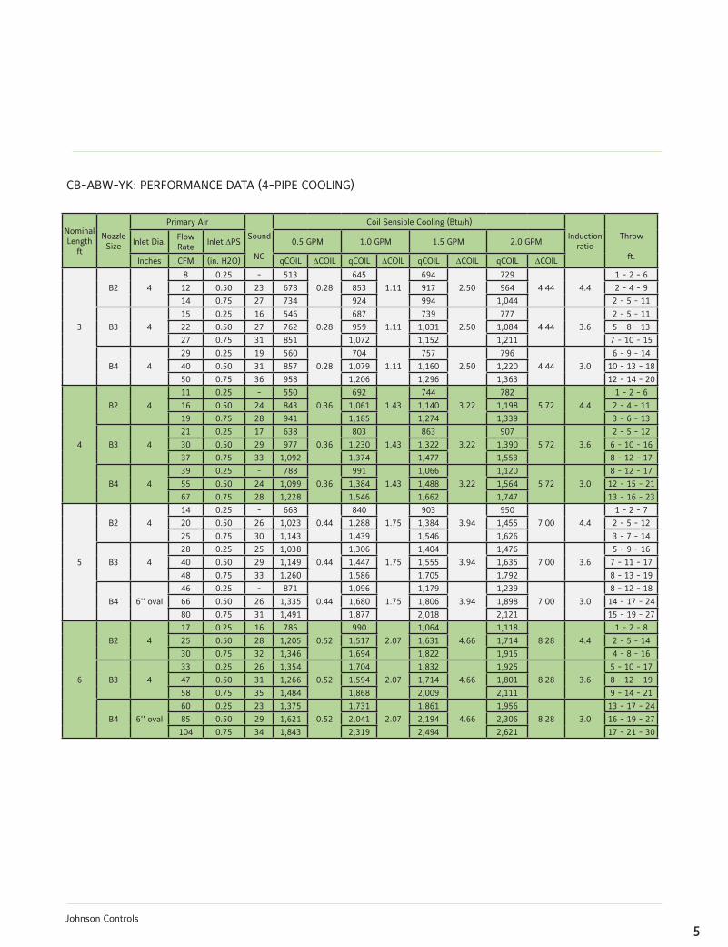
CB-ABW-YK: PERFORMANCE DATA (4-PIPE COOLING)
Nominal Length
ft
NozzleSize
Primary Air
Sound
NC
Coil Sensible Cooling (Btu/h)
Induction ratio
Throw
ft.
Inlet Dia.Flow Rate
Inlet DPS 0.5 GPM 1.0 GPM 1.5 GPM 2.0 GPM
Inches CFM (in. H2O) qCOIL DCOIL qCOIL DCOIL qCOIL DCOIL qCOIL DCOIL
3
B2 4
8 0.25 - 513
0.28
645
1.11
694
2.50
729
4.44 4.4
1 - 2 - 6
12 0.50 23 678 853 917 964 2 - 4 - 9
14 0.75 27 734 924 994 1,044 2 - 5 - 11
B3 4
15 0.25 16 546
0.28
687
1.11
739
2.50
777
4.44 3.6
2 - 5 - 11
22 0.50 27 762 959 1,031 1,084 5 - 8 - 13
27 0.75 31 851 1,072 1,152 1,211 7 - 10 - 15
B4 4
29 0.25 19 560
0.28
704
1.11
757
2.50
796
4.44 3.0
6 - 9 - 14
40 0.50 31 857 1,079 1,160 1,220 10 - 13 - 18
50 0.75 36 958 1,206 1,296 1,363 12 - 14 - 20
4
B2 4
11 0.25 - 550
0.36
692
1.43
744
3.22
782
5.72 4.4
1 - 2 - 6
16 0.50 24 843 1,061 1,140 1,198 2 - 4 - 11
19 0.75 28 941 1,185 1,274 1,339 3 - 6 - 13
B3 4
21 0.25 17 638
0.36
803
1.43
863
3.22
907
5.72 3.6
2 - 5 - 12
30 0.50 29 977 1,230 1,322 1,390 6 - 10 - 16
37 0.75 33 1,092 1,374 1,477 1,553 8 - 12 - 17
B4 4
39 0.25 - 788
0.36
991
1.43
1,066
3.22
1,120
5.72 3.0
8 - 12 - 17
55 0.50 24 1,099 1,384 1,488 1,564 12 - 15 - 21
67 0.75 28 1,228 1,546 1,662 1,747 13 - 16 - 23
5
B2 4
14 0.25 - 668
0.44
840
1.75
903
3.94
950
7.00 4.4
1 - 2 - 7
20 0.50 26 1,023 1,288 1,384 1,455 2 - 5 - 12
25 0.75 30 1,143 1,439 1,546 1,626 3 - 7 - 14
B3 4
28 0.25 25 1,038
0.44
1,306
1.75
1,404
3.94
1,476
7.00 3.6
5 - 9 - 16
40 0.50 29 1,149 1,447 1,555 1,635 7 - 11 - 17
48 0.75 33 1,260 1,586 1,705 1,792 8 - 13 - 19
B4 6'' oval
46 0.25 - 871
0.44
1,096
1.75
1,179
3.94
1,239
7.00 3.0
8 - 12 - 18
66 0.50 26 1,335 1,680 1,806 1,898 14 - 17 - 24
80 0.75 31 1,491 1,877 2,018 2,121 15 - 19 - 27
6
B2 4
17 0.25 16 786
0.52
990
2.07
1,064
4.66
1,118
8.28 4.4
1 - 2 - 8
25 0.50 28 1,205 1,517 1,631 1,714 2 - 5 - 14
30 0.75 32 1,346 1,694 1,822 1,915 4 - 8 - 16
B3 4
33 0.25 26 1,354
0.52
1,704
2.07
1,832
4.66
1,925
8.28 3.6
5 - 10 - 17
47 0.50 31 1,266 1,594 1,714 1,801 8 - 12 - 19
58 0.75 35 1,484 1,868 2,009 2,111 9 - 14 - 21
B4 6'' oval
60 0.25 23 1,375
0.52
1,731
2.07
1,861
4.66
1,956
8.28 3.0
13 - 17 - 24
85 0.50 29 1,621 2,041 2,194 2,306 16 - 19 - 27
104 0.75 34 1,843 2,319 2,494 2,621 17 - 21 - 30
6Johnson Controls
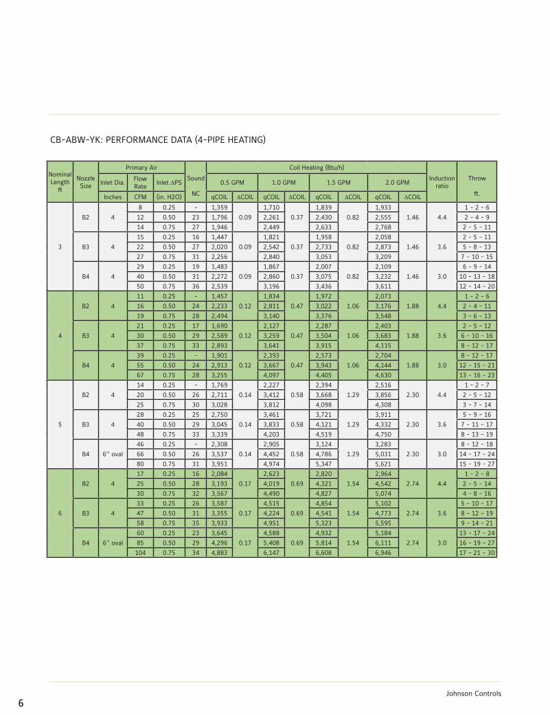
CB-ABW-YK: PERFORMANCE DATA (4-PIPE HEATING)
Nominal Length
ft
NozzleSize
Primary Air
Sound
NC
Coil Heating (Btu/h)
Induction ratio
Throw
ft.
Inlet Dia.Flow Rate
Inlet DPS 0.5 GPM 1.0 GPM 1.5 GPM 2.0 GPM
Inches CFM (in. H2O) qCOIL DCOIL qCOIL DCOIL qCOIL DCOIL qCOIL DCOIL
3
B2 4
8 0.25 - 1,359
0.09
1,710
0.37
1,839
0.82
1,933
1.46 4.4
1 - 2 - 6
12 0.50 23 1,796 2,261 2,430 2,555 2 - 4 - 9
14 0.75 27 1,946 2,449 2,633 2,768 2 - 5 - 11
B3 4
15 0.25 16 1,447
0.09
1,821
0.37
1,958
0.82
2,058
1.46 3.6
2 - 5 - 11
22 0.50 27 2,020 2,542 2,733 2,873 5 - 8 - 13
27 0.75 31 2,256 2,840 3,053 3,209 7 - 10 - 15
B4 4
29 0.25 19 1,483
0.09
1,867
0.37
2,007
0.82
2,109
1.46 3.0
6 - 9 - 14
40 0.50 31 2,272 2,860 3,075 3,232 10 - 13 - 18
50 0.75 36 2,539 3,196 3,436 3,611 12 - 14 - 20
4
B2 4
11 0.25 - 1,457
0.12
1,834
0.47
1,972
1.06
2,073
1.88 4.4
1 - 2 - 6
16 0.50 24 2,233 2,811 3,022 3,176 2 - 4 - 11
19 0.75 28 2,494 3,140 3,376 3,548 3 - 6 - 13
B3 4
21 0.25 17 1,690
0.12
2,127
0.47
2,287
1.06
2,403
1.88 3.6
2 - 5 - 12
30 0.50 29 2,589 3,259 3,504 3,683 6 - 10 - 16
37 0.75 33 2,893 3,641 3,915 4,115 8 - 12 - 17
B4 4
39 0.25 - 1,901
0.12
2,393
0.47
2,573
1.06
2,704
1.88 3.0
8 - 12 - 17
55 0.50 24 2,913 3,667 3,943 4,144 12 - 15 - 21
67 0.75 28 3,255 4,097 4,405 4,630 13 - 16 - 23
5
B2 4
14 0.25 - 1,769
0.14
2,227
0.58
2,394
1.29
2,516
2.30 4.4
1 - 2 - 7
20 0.50 26 2,711 3,412 3,668 3,856 2 - 5 - 12
25 0.75 30 3,028 3,812 4,098 4,308 3 - 7 - 14
B3 4
28 0.25 25 2,750
0.14
3,461
0.58
3,721
1.29
3,911
2.30 3.6
5 - 9 - 16
40 0.50 29 3,045 3,833 4,121 4,332 7 - 11 - 17
48 0.75 33 3,339 4,203 4,519 4,750 8 - 13 - 19
B4 6'' oval
46 0.25 - 2,308
0.14
2,905
0.58
3,124
1.29
3,283
2.30 3.0
8 - 12 - 18
66 0.50 26 3,537 4,452 4,786 5,031 14 - 17 - 24
80 0.75 31 3,951 4,974 5,347 5,621 15 - 19 - 27
6
B2 4
17 0.25 16 2,084
0.17
2,623
0.69
2,820
1.54
2,964
2.74 4.4
1 - 2 - 8
25 0.50 28 3,193 4,019 4,321 4,542 2 - 5 - 14
30 0.75 32 3,567 4,490 4,827 5,074 4 - 8 - 16
B3 4
33 0.25 26 3,587
0.17
4,515
0.69
4,854
1.54
5,102
2.74 3.6
5 - 10 - 17
47 0.50 31 3,355 4,224 4,541 4,773 8 - 12 - 19
58 0.75 35 3,933 4,951 5,323 5,595 9 - 14 - 21
B4 6'' oval
60 0.25 23 3,645
0.17
4,588
0.69
4,932
1.54
5,184
2.74 3.0
13 - 17 - 24
85 0.50 29 4,296 5,408 5,814 6,111 16 - 19 - 27
104 0.75 34 4,883 6,147 6,608 6,946 17 - 21 - 30
7Johnson Controls
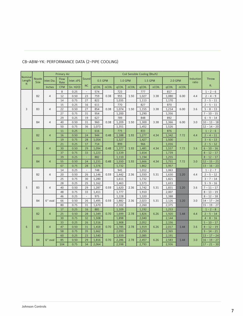
CB-ABW-YK: PERFORMANCE DATA (2-PIPE COOLING)
Nominal Length
ft
NozzleSize
Primary Air
Sound
NC
Coil Sensible Cooling (Btu/h)
Induction ratio
Throw
ft.
Inlet Dia.Flow Rate
Inlet DPS 0.5 GPM 1.0 GPM 1.5 GPM 2.0 GPM
Inches CFM (in. H2O) qCOIL DCOIL qCOIL DCOIL qCOIL DCOIL qCOIL DCOIL
3
B2 4
8 0.25 - 574
0.38
723
1.50
777
3.38
817
6.00 4.4
1 - 2 - 6
12 0.50 23 759 955 1,027 1,080 2 - 4 - 9
14 0.75 27 822 1,035 1,113 1,170 2 - 5 - 11
B3 4
15 0.25 16 611
0.38
770
1.50
827
3.38
870
6.00 3.6
2 - 5 - 11
22 0.50 27 854 1,074 1,155 1,214 5 - 8 - 13
27 0.75 31 954 1,200 1,290 1,356 7 - 10 - 15
B4 4
29 0.25 19 627
0.38
789
1.50
848
3.38
892
6.00 3.0
6 - 9 - 14
40 0.50 31 960 1,209 1,300 1,366 10 - 13 - 18
50 0.75 36 1,073 1,351 1,452 1,526 12 - 14 - 20
4
B2 4
11 0.25 - 616
0.48
775
1.93
833
4.34
876
7.72 4.4
1 - 2 - 6
16 0.50 24 944 1,188 1,277 1,342 2 - 4 - 11
19 0.75 28 1,054 1,327 1,427 1,500 3 - 6 - 13
B3 4
21 0.25 17 714
0.48
899
1.93
966
4.34
1,016
7.72 3.6
2 - 5 - 12
30 0.50 29 1,094 1,377 1,481 1,557 6 - 10 - 16
37 0.75 33 1,223 1,539 1,654 1,739 8 - 12 - 17
B4 4
39 0.25 - 882
0.48
1,110
1.93
1,194
4.34
1,255
7.72 3.0
8 - 12 - 17
55 0.50 24 1,231 1,550 1,666 1,751 12 - 15 - 21
67 0.75 28 1,376 1,732 1,862 1,957 13 - 16 - 23
5
B2 4
14 0.25 - 748
0.59
941
2.36
1,012
5.31
1,063
1.20 4.4
1 - 2 - 7
20 0.50 26 1,146 1,442 1,550 1,630 2 - 5 - 12
25 0.75 30 1,280 1,611 1,732 1,821 3 - 7 - 14
B3 4
28 0.25 25 1,162
0.59
1,463
2.36
1,573
5.31
1,653
1.20 3.6
5 - 9 - 16
40 0.50 29 1,287 1,620 1,742 1,831 7 - 11 - 17
48 0.75 33 1,411 1,777 1,910 2,007 8 - 13 - 19
B4 6'' oval
46 0.25 - 975
0.59
1,228
2.36
1,320
5.31
1,388
1.20 3.0
8 - 12 - 18
66 0.50 26 1,495 1,882 2,023 2,126 14 - 17 - 24
80 0.75 31 1,670 2,102 2,260 2,375 15 - 19 - 27
6
B2 4
17 0.25 16 881
0.70
1,109
2.78
1,192
6.26
1,253
1.44 4.4
1 - 2 - 8
25 0.50 28 1,349 1,699 1,826 1,920 2 - 5 - 14
30 0.75 32 1,508 1,898 2,040 2,144 4 - 8 - 16
B3 4
33 0.25 26 1,516
0.70
1,908
2.78
2,052
6.26
2,156
1.44 3.6
5 - 10 - 17
47 0.50 31 1,418 1,785 1,919 2,017 8 - 12 - 19
58 0.75 35 1,662 2,093 2,250 2,365 9 - 14 - 21
B4 6'' oval
60 0.25 23 1,540
0.70
1,939
2.78
2,085
6.26
2,191
1.44 3.0
13 - 17 - 24
85 0.50 29 1,816 2,286 2,457 2,583 16 - 19 - 27
104 0.75 34 2,064 2,598 2,793 2,936 17 - 21 - 30
8Johnson Controls
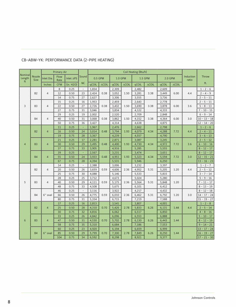
CB-ABW-YK: PERFORMANCE DATA (2-PIPE HEATING)
Nominal Length
ft
NozzleSize
Primary Air
Sound
NC
Coil Heating (Btu/h)
Induction ratio
Throw
ft.
Inlet Dia.Flow Rate
Inlet DPS 0.5 GPM 1.0 GPM 1.5 GPM 2.0 GPM
Inches CFM (in. H2O) qCOIL DCOIL qCOIL DCOIL qCOIL DCOIL qCOIL DCOIL
3
B2 4
8 0.25 - 1,834
0.38
2,309
1.50
2,482
3.38
2,609
6.00 4.4
1 - 2 - 6
12 0.50 23 2,424 3,052 3,281 3,449 2 - 4 - 9
14 0.75 27 2,627 3,306 3,555 3,736 2 - 5 - 11
B3 4
15 0.25 16 1,953
0.38
2,459
1.50
2,643
3.38
2,778
6.00 3.6
2 - 5 - 11
22 0.50 27 2,726 3,432 3,690 3,878 5 - 8 - 13
27 0.75 31 3,046 3,834 4,122 4,333 7 - 10 - 15
B4 4
29 0.25 19 2,002
0.38
2,520
1.50
2,709
3.38
2,848
6.00 3.0
6 - 9 - 14
40 0.50 31 3,068 3,862 4,152 4,364 10 - 13 - 18
50 0.75 36 3,427 4,314 4,638 4,875 12 - 14 - 20
4
B2 4
11 0.25 - 1,967
0.48
2,476
1.93
2,662
4.34
2,798
7.72 4.4
1 - 2 - 6
16 0.50 24 3,014 3,794 4,079 4,288 2 - 4 - 11
19 0.75 28 3,367 4,239 4,557 4,790 3 - 6 - 13
B3 4
21 0.25 17 2,281
0.48
2,871
1.93
3,087
4.34
3,245
7.72 3.6
2 - 5 - 12
30 0.50 29 3,495 4,400 4,730 4,972 6 - 10 - 16
37 0.75 33 3,905 4,916 5,285 5,555 8 - 12 - 17
B4 4
39 0.25 - 2,567
0.48
3,231
1.93
3,474
4.34
3,651
7.72 3.0
8 - 12 - 17
55 0.50 24 3,933 4,951 5,323 5,594 12 - 15 - 21
67 0.75 28 4,394 5,531 5,946 6,250 13 - 16 - 23
5
B2 4
14 0.25 - 2,388
0.59
3,006
2.36
3,232
5.31
3,397
1.20 4.4
1 - 2 - 7
20 0.50 26 3,659 4,606 4,952 5,205 2 - 5 - 12
25 0.75 30 4,088 5,146 5,533 5,815 3 - 7 - 14
B3 4
28 0.25 25 3,712
0.59
4,673
2.36
5,024
5.31
5,280
1.20
5 - 9 - 16
40 0.50 29 4,111 5,175 5,564 5,848 7 - 11 - 17
48 0.75 33 4,508 5,675 6,101 6,412 8 - 13 - 19
B4 6'' oval
46 0.25 - 3,116
0.59
3,922
2.36
4,217
5.31
4,432
1.20 3.0
8 - 12 - 18
66 0.50 26 4,775 6,010 6,462 6,792 14 - 17 - 24
80 0.75 31 5,334 6,715 7,219 7,588 15 - 19 - 27
6
B2 4
17 0.25 16 2,813
0.70
3,541
2.78
3,807
6.26
4,001
1.44 4.4
1 - 2 - 8
25 0.50 28 4,310 5,426 5,833 6,131 2 - 5 - 14
30 0.75 32 4,816 6,062 6,517 6,850 4 - 8 - 16
B3 4
33 0.25 26 4,842
0.70
6,096
2.78
6,553
6.26
6,888
1.44
5 - 10 - 17
47 0.50 31 4,530 5,702 6,130 6,443 8 - 12 - 19
58 0.75 35 5,310 6,684 7,186 7,553 9 - 14 - 21
B4 6'' oval
60 0.25 23 4,920
0.70
6,194
2.78
6,659
6.26
6,999
1.44
13 - 17 - 24
85 0.50 29 5,799 7,300 7,849 8,250 16 - 19 - 27
104 0.75 34 6,592 8,298 8,921 9,377 17 - 21 - 30
9Johnson Controls
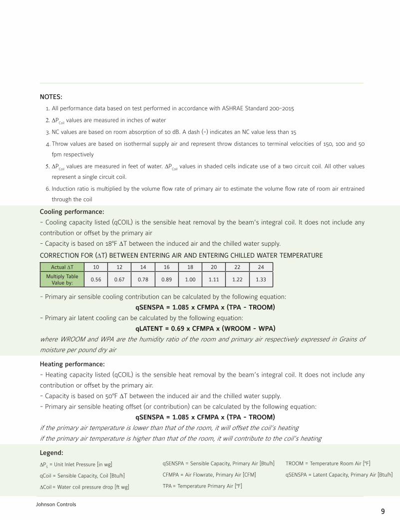
NOTES:
1. All performance data based on test performed in accordance with ASHRAE Standard 200-2015
2.DPCoil
values are measured in inches of water
3. NC values are based on room absorption of 10 dB. A dash (-) indicates an NC value less than 15
4. Throw values are based on isothermal supply air and represent throw distances to terminal velocities of 150, 100 and 50
fpm respectively
5.DPCoil
values are measured in feet of water. DPCoil
values in shaded cells indicate use of a two circuit coil. All other values
represent a single circuit coil.
6. Induction ratio is multiplied by the volume flow rate of primary air to estimate the volume flow rate of room air entrained
through the coil
Cooling performance:
- Cooling capacity listed (qCOIL) is the sensible heat removal by the beam’s integral coil. It does not include any
contribution or offset by the primary air
- Capacity is based on 18BF DT between the induced air and the chilled water supply.
- Primary air sensible cooling contribution can be calculated by the following equation:
qSENSPA = 1.085 x CFMPA x (TPA - TROOM)
- Primary air latent cooling can be calculated by the following equation:
qLATENT = 0.69 x CFMPA x (WROOM - WPA)
where WROOM and WPA are the humidity ratio of the room and primary air respectively expressed in Grains of
moisture per pound dry air
Heating performance:
- Heating capacity listed (qCOIL) is the sensible heat removal by the beam’s integral coil. It does not include any
contribution or offset by the primary air.
- Capacity is based on 50BF DT between the induced air and the chilled water supply.
- Primary air sensible heating offset (or contribution) can be calculated by the following equation:
qSENSPA = 1.085 x CFMPA x (TPA - TROOM)
if the primary air temperature is lower than that of the room, it will offset the coil’s heating
if the primary air temperature is higher than that of the room, it will contribute to the coil’s heating
CORRECTION FOR (DT) BETWEEN ENTERING AIR AND ENTERING CHILLED WATER TEMPERATURE
Actual DT 10 12 14 16 18 20 22 24
Multiply Table Value by:
0.56 0.67 0.78 0.89 1.00 1.11 1.22 1.33
Legend:
DPS = Unit Inlet Pressure [in wg]
qCoil = Sensible Capacity, Coil [Btu/h]
DCoil = Water coil pressure drop [ft wg]
qSENSPA = Sensible Capacity, Primary Air [Btu/h]
CFMPA = Air Flowrate, Primary Air [CFM]
TPA = Temperature Primary Air [BF]
TROOM = Temperature Room Air [BF]
qSENSPA = Latent Capacity, Primary Air [Btu/h]
10Johnson Controls
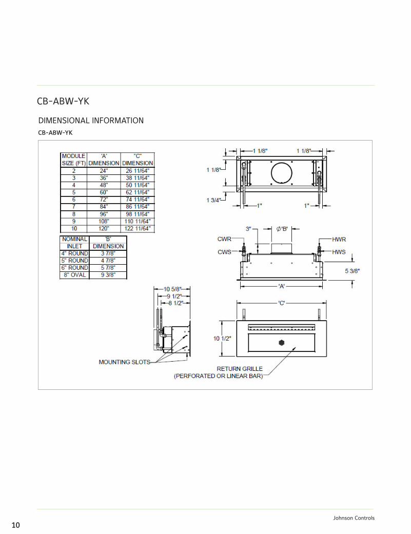
CB-ABW-YK
DIMENSIONAL INFORMATIONCB-ABW-YK
11Johnson Controls
Guide Specification:CB-ABW-YK Sidewall Active Chilled Beams
PART 1- GENERAL
1.01 Summary
This section describes the active chilled beams.
1.02 Submittals
Submit product data for all items complete with the
following information:
1. Operating weights and dimensions of all unit
assemblies.
2. Performance data, including sensible and latent
cooling capacities, nozzle types, primary and total supply
(primary plus induced) airflow rates, chilled (and where
applicable hot) water flow rates, noise levels in octave
bands, air and water side pressure losses and maximum
discharge air throw values.
3. Construction details including manufacturers
recommendations for installation, mounting and
connection.
PART 2- PRODUCTS
2.01 General
Materials and products required for the work of this
section shall not contain asbestos, polychlorinated
biphenyls (PCB) or other hazardous materials identified
by the engineer or owner.
2.02 Design
1. Furnish and install YORK® CB-ABW-YK sidewall
active chilled beams of sizes and capacities as indicated
on the drawings and within the mechanical equipment
schedules. The quantity and length of the beams shall
be as shown on the drawings, without EXCEPTION. The
beams shall be constructed and delivered to the job site
as single units.
2. The face of the beam shall consist of a room air
induction section of 50% free area perforated (optional
linear bar type) induction section with integral slot diffuser.
The face section shall include hinged fastening on each
side that allows the face to be swung out and removed.
The entire visible face section shall be finished in white
powder coat paint or as specified by the architect. All
visible internal surfaces shall be flat black.
3. The beams shall consist of a minimum 20 gauge
galvanized steel housing encasing the integral sensible
cooling coil and a plenum feeing a series of induction
nozzles. A single duct connection shall be provided on
either the side or top of the unit. The use of multiple duct
connections is NOT ACCEPTABLE.
4. Each beam shall be provided with a pressure tap
that may be used to measure the pressure differential
between the primary air plenum and the room. Airflow
calibration charts that relate this pressure differential
reading with the primary and beam supply airflow rates
shall be furnished with the beams.
5. Beams shall be provided with connections for either
2 or 4 pipe water connections as indicated on plans
and schedules. Four pipe configurations shall require
separate supply and return connections for chilled and
hot water. The coils shall be mounted vertically and
shall be manufactured with seamless copper tubing (½”
outside diameter) with minimum .016 inch wall thickness
mechanically fixed to aluminum fins. The aluminum fins
shall be limited to no more than ten (10) fins per inch.
The coil shall have a working pressure of at least 300
PSI, and be factory tested for leakage at a minimum
pressure of 360 PSI. Each chilled beam shall be provided
with factory integrated manual air vents. (OPTIONAL, coil
shall be provided with factory integrated drain fittings.)
12Johnson Controls
Unless otherwise specified, coil connections shall be
bare copper for field sweating to the water supply circuit.
Connections shall face upwards, be located near the
left end of the beam (when viewing into the primary air
connection). (OPTIONAL, the chilled water coil shall be
provided with NPT male threaded fittings. These fittings
must be suitable for field connection to a similar NPT
female flexible hose spigot and shall be at least 1½” long
to facilitate field connection (by others).
6. Beams shall be delivered clean, flushed and capped
to prevent ingress of dirt
2.03 Performance
1. All performance shall be in compliance with that
shown on the equipment schedule. Acoustical testing
shall have been performed in accordance with ASHRAE
Standard 200-2015.
2. Coils shall be rated in accordance with AHRI Standard
410, but their cooling and heating capacities shall be
established in accordance to ASHRAE Standard 200-
2015 for the specific application on the inlet side of the
submitted chilled beam.
3. Chilled water flow rates to the beams shall be limited
to that which results in a maximum ten (10) foot head
loss. Water flow velocities through the beam shall not
exceed 4 FPS.
PART 3- EXECUTION
3.02 Installation
1. Coordinate the size, tagging and capacity of the
beams to their proper location.
2. Chilled beams shall be fastened to structure/framing
utilizing all mounting slots provided.
3. Before connecting the supply water system(s) to
the beams, contractor shall flush the piping system(s)
to assure that all debris and other matter have been
removed.
4. Contractor shall perform connection of beams to the
chilled water circuit by method specified (hard connection
using sweated connection or connection using flexible
hoses).
5. Flexible connector hoses shall be furnished by others
(optionally by the manufacturer). Hoses shall be twenty
four (12, 18, or 24) inches in length and suitable for
operation with a bend radius as small as five (5) inches.
Connector hoses shall consist of a PTFE lined hose with
a wire braided jacket. The hoses shall be suitable for
operation in an environment between -40 and 200BF,
rated for a least 300 PSI and tested for leakage at a
minimum pressure of 360 PSI. Contractor shall assure
that the chilled water supplying the beams has been
properly treated in accordance to BSRIA publication AG
2/93.
6. Utilizing the locating pins provided, position diffuser
face, swinging face parallel to sidewall and lower into
installed position.
7. No power or direct control connections shall be
required for the operation of the chilled beam.
3.03 Cleaning and Protection
1. Air and water connections shall be covered before
shipment and remain so until final installation. Damaged
material due to improper site protection shall be cause
for rejection.
2. Clean equipment, repair damaged finishes as
required to restore beams to as-new appearance.

For more information www.york.com/chilledbeams
Johnson Controls, the Johnson Controls logo, and YORK® are trademarks of Johnson Controls, Inc., or its affiliates, in the United States of America and/or other countries.
r2016 Johnson Controls, Inc., P.O. Box 423, Milwaukee, WI 53201 Printed in USA PUBL-7949 (Rev. 08/16)
www.johnsoncontrols.com