Embed Size (px)
Citation preview

Yokogawa DX Serial Help
© 2012 Kepware Technologies

Yokogawa DX Serial Help
Table of ContentsTable of Contents 2Yokogawa DX Serial Help 3Overview 3
Device Setup 4Modem Setup 6
Data Types Description 7Address Descriptions 8DX102 Addressing 8DX104 Addressing 10DX106 Addressing 12DX112 Addressing 13DX204 Addressing 15DX208 Addressing 17DX210 Addressing 19DX220 Addressing 21DX230 Addressing 23MV100 Addressing 25MV200 Addressing 26
Automatic Tag Database Generation 29Error Descriptions 32Address Validation 32Missing address 32Device address '<address>' contains a syntax error 32Address '<address>' is out of range for the specified device or register 32Data Type '<type>' is not valid for device address '<address>' 33Device address '<address>' is Read Only 33Serial Communications 33COMn does not exist 33Error opening COMn 33COMn is in use by another application 33Unable to set comm parameters on COMn 34Communications error on '<channel name>' [<error mask>] 34Device Status Messages 34Device '<device name>' is not responding 34Unable to write to '<address>' on device '<device name>' 35
Index 36
www. kepware.com
2

Yokogawa DX Serial Help
Yokogawa DX Serial HelpHelp version 1.013
CONTENTS
OverviewWhat is the Yokogawa DX Serial Driver?
Device SetupHow do I configure a device for use with this driver?
Data Types DescriptionWhat data types does this driver support?
Address DescriptionsHow do I address a data location on a Yokogawa DX Serial device?
Automatic Tag Database GenerationHow can I easily configure tags for the Yokogawa DX Serial driver?
Error DescriptionsWhat error messages does the Yokogawa DX Serial driver produce?
OverviewThe Yokogawa DX Serial Driver provides an easy and reliable way to connect Yokogawa DX Serial devices to OPCClient applications, including HMI, SCADA, Historian, MES, ERP and countless custom applications. It is intendedfor use with Yokogawa Data Acquisition and Data Recorder devices that support RS232 or RS422 com-munications.
www. kepware.com
3

Yokogawa DX Serial Help
Device SetupSupported Yokogawa DevicesDX102DX104DX106DX112DX204DX208DX210DX220DX230MV100MV200
Supported Communication ParametersBaud Rate: 300, 600, 1200, 2400, 9600, 19200, or 38400Parity: None, Even, or OddData Bits: 8Stop Bits: 1 or 2Flow Control: None, RTS, or DTR
Note 1: Software handshaking is not available.
Note 2: This driver makes use of binary data formatting when reading information from Yokogawa devices. Thisrequires that a data bit setting of 8 be used.
RS-232 and RS-422/485 OperationYokogawa DX Serial devices support can support either RS-232 or RS-422/485 operation. This driver has beendesigned to support both modes of operation. The mode used depends on the configuration of the OPC Serverproject.
If intending to connect to a DX device using RS-232, select a Device ID of zero (0). This tells the driver to use theRS-232 mode for communications. If intending to use either RS-422 or RS-485 communications, select a DeviceID for each station that is between 1 and 16 for RS-422 and 1 and 31 for RS-485. When using RS-232, only con-figure one device on the channel.
Request TimeoutThis parameter specifies the amount of time that the driver will wait for a response from the device before givingup and going on to the next request. Long timeouts will only affect performance if a device is not responding. Thedefault setting is 1000 milliseconds. The valid range is 100 to 30000 milliseconds.
Retry AttemptsThis parameter specifies the number of times that the driver will retry a message before giving up and going onto the next message. The default setting is 3 retries. The valid range is 1 to 10.
Note: For more information, refer to the OPC Servers help documentation.
Device Configuration ParametersSpecial Data HandlingThe Special Data Handling setting allows the driver to be configured to return specific data values for numericalout of range and error conditions returned from the device. Special Data Handling options are none, +INF, and -INF. If Special Data Handling is set to NONE, special data values will be returned with the actual data valuereceived from the device (for example, the data value of a measuring channel Over Range would be returned as32,767 and the data value of a math channel Over Range would be returned as 2,147,450,879).
If Special Data Handling is set to +INF, special data values will be returned as a numerical representation of pos-itive infinity (#INF), with the exception of an Under Range condition that is always returned as negative infinity.When Special Data Handling is set to NEG INF, special data values will be returned as a numerical representationof negative infinity (-#INF), with the exception of an Over Range condition that is always returned as positiveinfinity.
Start math when startWhen checked, this option will inform the driver to send a command to the device at communication startup thatwill start the math computation.
www. kepware.com
4

Yokogawa DX Serial Help
Date & TimeThis parameter specifies the origin of the data value of the Date and Time data types which represent the dateand time of the latest data. Date & Time options are Device Time and System Time. If Device Time is selected, theDate and Time tags will return the date and time read from the device. This date and time represents the date andtime that the latest data was measured or computed based on the internal device clock. If System Time isselected, the Date and Time tags will return the date and time that the requested data was returned from thedevice based on the PC system clock.
Date FormatThis parameter specifies the format of the return string for the Date data type. Date formats can be specified asMM/DD/YY (month/day/year), YY/MM/DD (year/month/day) or DD/MM/YY (day/month/year).
Set clock when startWhen checked, this option will inform the driver to send a command to the device at communication startup thatwill set the device clock to the date and time settings of the system clock.
Cable DiagramsRS-232 Connections
Pin No. Signal Name Signal Meaning2 RD (Received Data) Received data from the PC. Input signal.3 SD (Send Data) Send data to the PC. Output signal.5 SG (Signal Ground) Signal ground.7 RS (Request to Send) Handshaking signal used when receiving data from the PC.
Output signal.8 CS (Clear to Send) Handshaking signal used when sending data to the PC.
Input signal.* Pins 1, 4, 6, and 9 are not used.
RS-422 Connections
Pin No. Signal Name Signal MeaningFG (Frame Ground) Case ground of the DX.SG (Signal Ground) Signal ground.SDB (Send Data B) Send data B (+).SDA (Send Data A) Send data A (-).RDB (Received Data B) Received data B (+).RDA (Received Data A) Received data A (-).
www. kepware.com
5

Yokogawa DX Serial Help
Note: RS-232 and RS-422 configuration is done from the setup menu of the Yokogawa DX recorder.
Modem SetupThis driver supports modem functionality. For more information, please refer to the topic "Modem Support" in theOPC Server Help documentation.
www. kepware.com
6

Yokogawa DX Serial Help
Data Types Description
Data Type DescriptionBoolean Single bitByte Unsigned 8 bit valueWord Unsigned 16 bit valueShort Signed 16 bit valueFloat 32 bit floating point valueDouble 64 bit floating point valueString Null terminated ASCII string
www. kepware.com
7

Yokogawa DX Serial Help
Address DescriptionsAddress specifications vary depending on the model in use. Select a link from the following list to obtain specificaddress information for the model of interest.
DX102 AddressingDX104 AddressingDX106 AddressingDX112 AddressingDX204 AddressingDX208 AddressingDX210 AddressingDX220 AddressingDX230 AddressingMV100 AddressingMV200 Addressing
DX102 AddressingThe driver supports the following addresses for this device. The default data type for each address type is shownin bold.
Measured ChannelsAddress Type Format Range Data Type AccessProcess Value of Channel CHxx or CHxx.PV 01-02 Double, Float Read OnlyAlarm Summary of Channel CHxx.Alarm 01-02 Short, Word, Byte Read OnlyAlarm Level1 Status of Channel CHxx.Alarm1 01-02 Short, Word, Byte Read OnlyAlarm Level2 Status of Channel CHxx.Alarm2 01-02 Short, Word, Byte Read OnlyAlarm Level3 Status of Channel CHxx.Alarm3 01-02 Short, Word, Byte Read OnlyAlarm Level4 Status of Channel CHxx.Alarm4 01-02 Short, Word, Byte Read OnlySet and Read Level1 Alarm Setpoint CHxx.ASP1 01-02 Double, Float Read/WriteSet and Read Level2 Alarm Setpoint CHxx.ASP2 01-02 Double, Float Read/WriteSet and Read Level3 Alarm Setpoint CHxx.ASP3 01-02 Double, Float Read/WriteSet and Read Level4 Alarm Setpoint CHxx.ASP4 01-02 Double, Float Read/WriteUpper Scale Value of Channel* CHxx.scale_Hi 01-02 Double, Float Read OnlyLower Scale Value of Channel* CHxx.scale_Lo 01-02 Double, Float Read OnlyUnit String of Channel* CHxx.unit 01-02 String Read OnlyTagname of Channel* CHxx.tag 01-02 String Read OnlyStatus of Channel* CHxx.status 01-02 String Read OnlyLowest Measuring Channel* CH.Low Short, Word, Byte Read OnlyHighest Measuring Channel* CH.High Short, Word, Byte Read Only
Math ChannelsAddress Type Format Range Data Type AccessProcess Value of Math Channel CHxx or CHxx.PV 31-34 Double, Float Read OnlyAlarm Summary of Math Channel CHxx.Alarm 31-34 Short, Word, Byte Read OnlyAlarm Level1 Status of Math Channel CHxx.Alarm1 31-34 Short, Word, Byte Read OnlyAlarm Level2 Status of Math Channel CHxx.Alarm2 31-34 Short, Word, Byte Read OnlyAlarm Level3 Status of Math Channel CHxx.Alarm3 31-34 Short, Word, Byte Read OnlyAlarm Level4 Status of Math Channel CHxx.Alarm4 31-34 Short, Word, Byte Read OnlySet and Read Level1 Alarm Setpoint CHxx.ASP1 31-34 Double, Float Read/WriteSet and Read Level2 Alarm Setpoint CHxx.ASP2 31-34 Double, Float Read/WriteSet and Read Level3 Alarm Setpoint CHxx.ASP3 31-34 Double, Float Read/WriteSet and Read Level4 Alarm Setpoint CHxx.ASP4 31-34 Double, Float Read/WriteUpper Scale Value of Math Channel* CHxx.scale_Hi 31-34 Double, Float Read OnlyLower Scale Value of Math Channel* CHxx.scale_Lo 31-34 Double, Float Read OnlyUnit String of Math Channel* CHxx.unit 01-34 String Read OnlyTagname of Math Channel* CHxx.tag 01-34 String Read Only
www. kepware.com
8

Yokogawa DX Serial Help
Status of Math Channel* CHxx.status 01-34 String Read OnlyLowest Math Channel* CHA.Low Short, Word, Byte Read OnlyHighest Math Channel* CHA.High Short, Word, Byte Read Only
Initialized DataData associated with the addresses denoted by an (*), are read from the device only at the start of a com-munications session. Once read, the values will not be refreshed until the server has been restarted or the"Reset" tag has been invoked. To invoke a reset, a non-zero value must be written to the Reset tag. Once theReset tag has been invoked the driver will reinitialize all startup data from the device.
Alarm SetpointsData values for Alarm Setpoints that are undefined in the device will be returned as +INF. Data values can only bewritten to Alarm Setpoints that are defined in the device. Write operations to undefined Alarm Setpoints willreturn an error. Write operations are available only for users logged in at the Administrator level and will returnan error otherwise. Alarm setpoint values are read one channel at a time. For devices with a large number of chan-nels, increasing the scan rate of ASP items and/or reducing the number of active ASP items will increase the readperformance of the PV and alarm data.
ScalesData values for Scale_Hi and Scale_Lo for channels that are skipped will be returned as +INF.
Tag NamesFor devices that do not support tag names and channels that have unspecified tag names, the driver will con-struct an internal tag name based on the channel number, for example, the tag name of address 'CH01' will bereturned as 'CH01'.
General Device DataAddress Type Format Range Data Type AccessAdministrator Level* Admin Boolean Read OnlyDate of Last Data Date String Read OnlyTime of Last Data Time String Read OnlyModel Name of Device* Model String Read OnlyMath Communication Data* CDxx 01-04 Float Read/WriteControl Math Execution MathControl Short, Word, Byte Write OnlyReset Alarms AlarmReset Boolean Write OnlyControl Command and Response Command String Read/WritePrevious Screen PreScreen Boolean Write OnlyDirect Reloading of Configuration Reset Boolean Write Only
Administrator LevelThe Admin address type has a value of '1' or 'true' when the user has logged on at the Administrator level and avalue of '0' or 'false' when the user has logged on at the User level.
Math Communication DataThe CD address type is only valid for devices equipped with the math option and write operations to CD addressesfor non-math equipped devices will return an error. Write operations are available only for users logged in at theAdministrator level and will return an error otherwise. Note that CD addresses are initialized (read) at startup andwill not be reread unless the server is restarted or the Reset tag is invoked. For more information, refer toNoteon Initialized Data.
Model Name of DeviceThe Model address type will have a string value of 'DX100' or 'DX200', indicating the model series returned bythe device.
Control Math ExecutionThe MathControl address type is only available for devices equipped with the math option and write operations tothe MathControl tag for non-math equipped devices will return an error.
Control Command and ResponseThe Command address allows the user to send a string command and receive a string response to and from thedevice. This allows the user to send any command to the device, including commands not directly supported bythe driver. This tag is only available to users logged in at the Administrator level and write operations will returnan error otherwise. Warning: Write operations using the Command address should be performed with extremecaution!
www. kepware.com
9

Yokogawa DX Serial Help
Note 1: The actual number of addresses available for of each type is dependent on the configuration of the Yoko-gawa device. If at runtime the driver finds that an address is not present in the device, the driver will post anerror message and remove the tag from its scan list.
Note 2: Addresses that have Write Only access are assigned a default access of Read/Write. However, datavalues are unreadable for these addresses and the associated tags are not included in the scan list. The currentdata value for these tags will always be 0 for numeric data types and null string for string data types.
DX104 AddressingThe driver supports the following addresses for this device. The default data type for each address type is shownin bold.
Measured ChannelsAddress Type Format Range Data Type AccessProcess Value of Channel CHxx or CHxx.PV 01-04 Double, Float Read OnlyAlarm Summary of Channel CHxx.Alarm 01-04 Short, Word, Byte Read OnlyAlarm Level1 Status of Channel CHxx.Alarm1 01-04 Short, Word, Byte Read OnlyAlarm Level2 Status of Channel CHxx.Alarm2 01-04 Short, Word, Byte Read OnlyAlarm Level3 Status of Channel CHxx.Alarm3 01-04 Short, Word, Byte Read OnlyAlarm Level4 Status of Channel CHxx.Alarm4 01-04 Short, Word, Byte Read OnlySet and Read Level1 Alarm Setpoint CHxx.ASP1 01-04 Double, Float Read/WriteSet and Read Level2 Alarm Setpoint CHxx.ASP2 01-04 Double, Float Read/WriteSet and Read Level3 Alarm Setpoint CHxx.ASP3 01-04 Double, Float Read/WriteSet and Read Level4 Alarm Setpoint CHxx.ASP4 01-04 Double, Float Read/WriteUpper Scale Value of Channel* CHxx.scale_Hi 01-04 Double, Float Read OnlyLower Scale Value of Channel* CHxx.scale_Lo 01-04 Double, Float Read OnlyUnit String of Channel* CHxx.unit 01-04 String Read OnlyTagname of Channel* CHxx.tag 01-04 String Read OnlyStatus of Channel* CHxx.status 01-04 String Read OnlyLowest Measuring Channel* CH.Low Short, Word, Byte Read OnlyHighest Measuring Channel* CH.High Short, Word, Byte Read Only
Math ChannelsAddress Type Format Range Data Type AccessProcess Value of Math Channel CHxx or CHxx.PV 31-34 Double, Float Read OnlyAlarm Summary of Math Channel CHxx.Alarm 31-34 Short, Word, Byte Read OnlyAlarm Level1 Status of Math Channel CHxx.Alarm1 31-34 Short, Word, Byte Read OnlyAlarm Level2 Status of Math Channel CHxx.Alarm2 31-34 Short, Word, Byte Read OnlyAlarm Level3 Status of Math Channel CHxx.Alarm3 31-34 Short, Word, Byte Read OnlyAlarm Level4 Status of Math Channel CHxx.Alarm4 31-34 Short, Word, Byte Read OnlySet and Read Level1 Alarm Setpoint CHxx.ASP1 31-34 Double, Float Read/WriteSet and Read Level2 Alarm Setpoint CHxx.ASP2 31-34 Double, Float Read/WriteSet and Read Level3 Alarm Setpoint CHxx.ASP3 31-34 Double, Float Read/WriteSet and Read Level4 Alarm Setpoint CHxx.ASP4 31-34 Double, Float Read/WriteUpper Scale Value of Math Channel* CHxx.scale_Hi 31-34 Double, Float Read OnlyLower Scale Value of Math Channel* CHxx.scale_Lo 31-34 Double, Float Read OnlyUnit String of Math Channel* CHxx.unit 31-34 String Read OnlyTagname of Math Channel* CHxx.tag 31-34 String Read OnlyStatus of Math Channel* CHxx.status 31-34 String Read OnlyLowest Math Channel* CHA.Low Short,Word, Byte Read OnlyHighest Math Channel* CHA.High Short, Word, Byte Read Only
Initialized DataData associated with the addresses denoted by an (*), are read from the device only at the start of a com-munications session. Once read, the values will not be refreshed until the server has been restarted or the"Reset" tag has been invoked. To invoke a reset, a non-zero value must be written to the Reset tag. Once theReset tag has been invoked the driver will reinitialize all startup data from the device.
Alarm Setpoints
www. kepware.com
10

Yokogawa DX Serial Help
Data values for Alarm Setpoints that are undefined in the device will be returned as +INF. Data values can only bewritten to Alarm Setpoints that are defined in the device. Write operations to undefined Alarm Setpoints willreturn an error. Write operations are available only for users logged in at the Administrator level and will returnan error otherwise. Alarm setpoint values are read one channel at a time. For devices with a large number of chan-nels, increasing the scan rate of ASP items and/or reducing the number of active ASP items will increase the readperformance of the PV and alarm data.
ScalesData values for Scale_Hi and Scale_Lo for channels that are skipped will be returned as +INF.
Tag NamesFor devices that do not support tag names and channels that have unspecified tag names, the driver will con-struct an internal tag name based on the channel number, for example, the tag name of address 'CH01' will bereturned as 'CH01'.
General Device DataAddress Type Format Range Data Type AccessAdministrator Level* Admin Boolean Read OnlyDate of Last Data Date String Read OnlyTime of Last Data Time String Read OnlyModel Name of Device* Model String Read OnlyMath Communication Data* CDxx 01-04 Float Read/WriteControl Math Execution MathControl Short, Word, Byte Write OnlyReset Alarms AlarmReset Boolean Write OnlyControl Command and Response Command String Read/WritePrevious Screen PreScreen Boolean Write OnlyDirect Reloading of Configuration Reset Boolean Write Only
Administrator LevelThe Admin address type has a value of '1' or 'true' when the user has logged on at the Administrator level and avalue of '0' or 'false' when the user has logged on at the User level.
Math Communication DataThe CD address type is only valid for devices equipped with the math option and write operations to CD addressesfor non-math equipped devices will return an error. Write operations are available only for users logged in at theAdministrator level and will return an error otherwise. Note that CD addresses are initialized (read) at startup andwill not be reread unless the server is restarted or the Reset tag is invoked. For more information, refer toNoteon Initialized Data.
Model Name of DeviceThe Model address type will have a string value of 'DX100' or 'DX200', indicating the model series returned bythe device.
Control Math ExecutionThe MathControl address type is only available for devices equipped with the math option and write operations tothe MathControl tag for non-math equipped devices will return an error.
Control Command and ResponseThe Command address allows the user to send a string command and receive a string response to and from thedevice. This allows the user to send any command to the device, including commands not directly supported bythe driver. This tag is only available to users logged in at the Administrator level and write operations will returnan error otherwise. Warning: Write operations using the Command address should be performed with extremecaution!
Note 1: The actual number of addresses available for of each type is dependent on the configuration of the Yoko-gawa device. If at runtime the driver finds that an address is not present in the device, the driver will post anerror message and remove the tag from its scan list.
Note 2: Addresses that have Write Only access are assigned a default access of Read/Write. However, datavalues are unreadable for these addresses and the associated tags are not included in the scan list. The currentdata value for these tags will always be 0 for numeric data types and null string for string data types.
www. kepware.com
11

Yokogawa DX Serial Help
DX106 AddressingThe driver supports the following addresses for this device. The default data type for each address type is shownin bold.
Measured ChannelsAddress Type Format Range Data Type AccessProcess Value of Channel CHxx or CHxx.PV 01-06 Double, Float Read OnlyAlarm Summary of Channel CHxx.Alarm 01-06 Short, Word, Byte Read OnlyAlarm Level1 Status of Channel CHxx.Alarm1 01-06 Short, Word, Byte Read OnlyAlarm Level2 Status of Channel CHxx.Alarm2 01-06 Short, Word, Byte Read OnlyAlarm Level3 Status of Channel CHxx.Alarm3 01-06 Short, Word, Byte Read OnlyAlarm Level4 Status of Channel CHxx.Alarm4 01-06 Short, Word, Byte Read OnlySet and Read Level1 Alarm Setpoint CHxx.ASP1 01-06 Double, Float Read/WriteSet and Read Level2 Alarm Setpoint CHxx.ASP2 01-06 Double, Float Read/WriteSet and Read Level3 Alarm Setpoint CHxx.ASP3 01-06 Double, Float Read/WriteSet and Read Level4 Alarm Setpoint CHxx.ASP4 01-06 Double, Float Read/WriteUpper Scale Value of Channel* CHxx.scale_Hi 01-06 Double, Float Read OnlyLower Scale Value of Channel* CHxx.scale_Lo 01-06 Double, Float Read OnlyUnit String of Channel* CHxx.unit 01-06 String Read OnlyTagname of Channel* CHxx.tag 01-06 String Read OnlyStatus of Channel* CHxx.status 01-06 String Read OnlyLowest Measuring Channel* CH.Low Short, Word, Byte Read OnlyHighest Measuring Channel* CH.High Short, Word, Byte Read Only
Math ChannelsAddress Type Format Range Data Type AccessProcess Value of Math Channel CHxx or CHxx.PV 31-42 Double, Float Read OnlyAlarm Summary of Math Channel CHxx.Alarm 31-42 Short, Word, Byte Read OnlyAlarm Level1 Status of Math Channel CHxx.Alarm1 31-42 Short, Word, Byte Read OnlyAlarm Level2 Status of Math Channel CHxx.Alarm2 31-42 Short, Word, Byte Read OnlyAlarm Level3 Status of Math Channel CHxx.Alarm3 31-42 Short, Word, Byte Read OnlyAlarm Level4 Status of Math Channel CHxx.Alarm4 31-42 Short, Word, Byte Read OnlySet and Read Level1 Alarm Setpoint CHxx.ASP1 31-42 Double, Float Read/WriteSet and Read Level2 Alarm Setpoint CHxx.ASP2 31-42 Double, Float Read/WriteSet and Read Level3 Alarm Setpoint CHxx.ASP3 31-42 Double, Float Read/WriteSet and Read Level4 Alarm Setpoint CHxx.ASP4 31-42 Double, Float Read/WriteUpper Scale Value of Math Channel* CHxx.scale_Hi 31-42 Double, Float Read OnlyLower Scale Value of Math Channel* CHxx.scale_Lo 31-42 Double, Float Read OnlyUnit String of Math Channel* CHxx.unit 01-42 String Read OnlyTagname of Math Channel* CHxx.tag 01-42 String Read OnlyStatus of Math Channel* CHxx.status 01-42 String Read OnlyLowest Math Channel* CHA.Low Short,Word, Byte Read OnlyHighest Math Channel* CHA.High Short, Word, Byte Read Only
Initialized DataData associated with the addresses denoted by an (*), are read from the device only at the start of a com-munications session. Once read, the values will not be refreshed until the server has been restarted or the"Reset" tag has been invoked. To invoke a reset, a non-zero value must be written to the Reset tag. Once theReset tag has been invoked the driver will reinitialize all startup data from the device.
Alarm SetpointsData values for Alarm Setpoints that are undefined in the device will be returned as +INF. Data values can only bewritten to Alarm Setpoints that are defined in the device. Write operations to undefined Alarm Setpoints willreturn an error. Write operations are available only for users logged in at the Administrator level and will returnan error otherwise. Alarm setpoint values are read one channel at a time. For devices with a large number of chan-nels, increasing the scan rate of ASP items and/or reducing the number of active ASP items will increase the readperformance of the PV and alarm data.
Scales
www. kepware.com
12

Yokogawa DX Serial Help
Data values for Scale_Hi and Scale_Lo for channels that are skipped will be returned as +INF.
Tag NamesFor devices that do not support tag names and channels that have unspecified tag names, the driver will con-struct an internal tag name based on the channel number, for example, the tag name of address 'CH01' will bereturned as 'CH01'.
General Device DataAddress Type Format Range Data Type AccessAdministrator Level* Admin Boolean Read OnlyDate of Last Data Date String Read OnlyTime of Last Data Time String Read OnlyModel Name of Device* Model String Read OnlyMath Communication Data* CDxx 01-12 Float Read/WriteControl Math Execution MathControl Short, Word, Byte Write OnlyReset Alarms AlarmReset Boolean Write OnlyControl Command and Response Command String Read/WritePrevious Screen PreScreen Boolean Write OnlyDirect Reloading of Configuration Reset Boolean Write Only
Administrator LevelThe Admin address type has a value of '1' or 'true' when the user has logged on at the Administrator level and avalue of '0' or 'false' when the user has logged on at the User level.
Math Communication DataThe CD address type is only valid for devices equipped with the math option and write operations to CD addressesfor non-math equipped devices will return an error. Write operations are available only for users logged in at theAdministrator level and will return an error otherwise. Note that CD addresses are initialized (read) at startup andwill not be reread unless the server is restarted or the Reset tag is invoked. For more information, refer toNoteon Initialized Data.
Model Name of DeviceThe Model address type will have a string value of 'DX100' or 'DX200', indicating the model series returned bythe device.
Control Math ExecutionThe MathControl address type is only available for devices equipped with the math option and write operations tothe MathControl tag for non-math equipped devices will return an error.
Control Command and ResponseThe Command address allows the user to send a string command and receive a string response to and from thedevice. This allows the user to send any command to the device, including commands not directly supported bythe driver. This tag is only available to users logged in at the Administrator level and write operations will returnan error otherwise. Warning: Write operations using the Command address should be performed with extremecaution!
Note 1: The actual number of addresses available for of each type is dependent on the configuration of the Yoko-gawa device. If at runtime the driver finds that an address is not present in the device, the driver will post anerror message and remove the tag from its scan list.
Note 2: Addresses that have Write Only access are assigned a default access of Read/Write. However, datavalues are unreadable for these addresses and the associated tags are not included in the scan list. The currentdata value for these tags will always be 0 for numeric data types and null string for string data types.
DX112 AddressingThe driver supports the following addresses for this device. The default data type for each address type is shownin bold.
Measured ChannelsAddress Type Format Range Data Type AccessProcess Value of Channel CHxx or CHxx.PV 01-12 Double, Float Read OnlyAlarm Summary of Channel CHxx.Alarm 01-12 Short, Word, Byte Read OnlyAlarm Level1 Status of Channel CHxx.Alarm1 01-12 Short, Word, Byte Read Only
www. kepware.com
13

Yokogawa DX Serial Help
Alarm Level2 Status of Channel CHxx.Alarm2 01-12 Short, Word, Byte Read OnlyAlarm Level3 Status of Channel CHxx.Alarm3 01-12 Short, Word, Byte Read OnlyAlarm Level4 Status of Channel CHxx.Alarm4 01-12 Short, Word, Byte Read OnlySet and Read Level1 Alarm Setpoint CHxx.ASP1 01-12 Double, Float Read/WriteSet and Read Level2 Alarm Setpoint CHxx.ASP2 01-12 Double, Float Read/WriteSet and Read Level3 Alarm Setpoint CHxx.ASP3 01-12 Double, Float Read/WriteSet and Read Level4 Alarm Setpoint CHxx.ASP4 01-12 Double, Float Read/WriteUpper Scale Value of Channel* CHxx.scale_Hi 01-12 Double, Float Read OnlyLower Scale Value of Channel* CHxx.scale_Lo 01-12 Double, Float Read OnlyUnit String of Channel* CHxx.unit 01-12 String Read OnlyTagname of Channel* CHxx.tag 01-12 String Read OnlyStatus of Channel* CHxx.status 01-12 String Read OnlyLowest Measuring Channel* CH.Low Short, Word, Byte Read OnlyHighest Measuring Channel* CH.High Short, Word, Byte Read Only
Math ChannelsAddress Type Format Range Data Type AccessProcess Value of Math Channel CHxx or CHxx.PV 31-42 Double, Float Read OnlyAlarm Summary of Math Channel CHxx.Alarm 31-42 Short, Word, Byte Read OnlyAlarm Level1 Status of Math Channel CHxx.Alarm1 31-42 Short, Word, Byte Read OnlyAlarm Level2 Status of Math Channel CHxx.Alarm2 31-42 Short, Word, Byte Read OnlyAlarm Level3 Status of Math Channel CHxx.Alarm3 31-42 Short, Word, Byte Read OnlyAlarm Level4 Status of Math Channel CHxx.Alarm4 31-42 Short, Word, Byte Read OnlySet and Read Level1 Alarm Setpoint CHxx.ASP1 31-42 Double, Float Read/WriteSet and Read Level2 Alarm Setpoint CHxx.ASP2 31-42 Double, Float Read/WriteSet and Read Level3 Alarm Setpoint CHxx.ASP3 31-42 Double, Float Read/WriteSet and Read Level4 Alarm Setpoint CHxx.ASP4 31-42 Double, Float Read/WriteUpper Scale Value of Math Channel* CHxx.scale_Hi 31-42 Double, Float Read OnlyLower Scale Value of Math Channel* CHxx.scale_Lo 31-42 Double, Float Read OnlyUnit String of Math Channel* CHxx.unit 01-42 String Read OnlyTagname of Math Channel* CHxx.tag 01-42 String Read OnlyStatus of Math Channel* CHxx.status 01-42 String Read OnlyLowest Math Channel* CHA.Low Short,Word, Byte Read OnlyHighest Math Channel* CHA.High Short, Word, Byte Read Only
Initialized DataData associated with the addresses denoted by an (*) are read from the device only at the start of a com-munications session. Once read, the values will not be refreshed until the server has been restarted or the"Reset" tag has been invoked. To invoke a reset, a non zero value must be written to the Reset tag. Once the Resettag has been invoked the driver will reinitialize all startup data from the device.
Alarm SetpointsData values for Alarm Setpoints that are undefined in the device will be returned as +INF. Data values can only bewritten to Alarm Setpoints that are defined in the device. Write operations to undefined Alarm Setpoints willreturn an error. Write operations are available only for users logged in at the Administrator level and will returnan error otherwise. Alarm setpoint values are read one channel at a time. For devices with a large number of chan-nels, increasing the scan rate of ASP items and/or reducing the number of active ASP items will increase the readperformance of the PV and alarm data.
ScalesData values for Scale_Hi and Scale_Lo for channels that are skipped will be returned as +INF.
Tag NamesFor devices that do not support tag names and channels that have unspecified tag names, the driver will con-struct an internal tag name based on the channel number, for example, the tag name of address 'CH01' will bereturned as 'CH01'.
General Device DataAddress Type Format Range Data Type Access
www. kepware.com
14

Yokogawa DX Serial Help
Administrator Level* Admin Boolean Read OnlyDate of Last Data Date String Read OnlyTime of Last Data Time String Read OnlyModel Name of Device* Model String Read OnlyMath Communication Data* CDxx 01-12 Float Read/WriteControl Math Execution MathControl Short, Word, Byte Write OnlyReset Alarms AlarmReset Boolean Write OnlyControl Command and Response Command String Read/WritePrevious Screen PreScreen Boolean Write OnlyDirect Reloading of Configuration Reset Boolean Write Only
Administrator LevelThe Admin address type has a value of '1' or 'true' when the user has logged on at the Administrator level and avalue of '0' or 'false' when the user has logged on at the User level.
Math Communication DataThe CD address type is only valid for devices equipped with the math option and write operations to CD addressesfor non-math equipped devices will return an error. Write operations are available only for users logged in at theAdministrator level and will return an error otherwise. Note that CD addresses are initialized (read) at startup andwill not be reread unless the server is restarted or the Reset tag is invoked. For more information, refer toNoteon Initialized Data.
Model Name of DeviceThe Model address type will have a string value of 'DX100' or 'DX200', indicating the model series returned bythe device.
Control Math ExecutionThe MathControl address type is only available for devices equipped with the math option and write operations tothe MathControl tag for non-math equipped devices will return an error.
Control Command and ResponseThe Command address allows the user to send a string command and receive a string response to and from thedevice. This allows the user to send any command to the device, including commands not directly supported bythe driver. This tag is only available to users logged in at the Administrator level and write operations will returnan error otherwise. Warning: Write operations using the Command address should be performed with extremecaution!
Note 1: The actual number of addresses available for of each type is dependent on the configuration of the Yoko-gawa device. If at runtime the driver finds that an address is not present in the device, the driver will post anerror message and remove the tag from its scan list.
Note 2: Addresses that have Write Only access are assigned a default access of Read/Write. However, datavalues are unreadable for these addresses and the associated tags are not included in the scan list. The currentdata value for these tags will always be 0 for numeric data types and null string for string data types.
DX204 AddressingThe driver supports the following addresses for this device. The default data type for each address type is shownin bold.
Measured ChannelsAddress Type Format Range Data Type AccessProcess Value of Channel CHxx or CHxx.PV 01-04 Double, Float Read OnlyAlarm Summary of Channel CHxx.Alarm 01-04 Short, Word, Byte Read OnlyAlarm Level1 Status of Channel CHxx.Alarm1 01-04 Short, Word, Byte Read OnlyAlarm Level2 Status of Channel CHxx.Alarm2 01-04 Short, Word, Byte Read OnlyAlarm Level3 Status of Channel CHxx.Alarm3 01-04 Short, Word, Byte Read OnlyAlarm Level4 Status of Channel CHxx.Alarm4 01-04 Short, Word, Byte Read OnlySet and Read Level1 Alarm Setpoint CHxx.ASP1 01-04 Double, Float Read/WriteSet and Read Level2 Alarm Setpoint CHxx.ASP2 01-04 Double, Float Read/WriteSet and Read Level3 Alarm Setpoint CHxx.ASP3 01-04 Double, Float Read/WriteSet and Read Level4 Alarm Setpoint CHxx.ASP4 01-04 Double, Float Read/Write
www. kepware.com
15

Yokogawa DX Serial Help
Upper Scale Value of Channel* CHxx.scale_Hi 01-04 Double, Float Read OnlyLower Scale Value of Channel* CHxx.scale_Lo 01-04 Double, Float Read OnlyUnit String of Channel* CHxx.unit 01-04 String Read OnlyTagname of Channel* CHxx.tag 01-04 String Read OnlyStatus of Channel* CHxx.status 01-04 String Read OnlyLowest Measuring Channel* CH.Low Short, Word, Byte Read OnlyHighest Measuring Channel* CH.High Short, Word, Byte Read Only
Math ChannelsAddress Type Format Range Data Type AccessProcess Value of Math Channel CHxx or CHxx.PV 31-38 Double, Float Read OnlyAlarm Summary of Math Channel CHxx.Alarm 31-38 Short, Word, Byte Read OnlyAlarm Level1 Status of Math Channel CHxx.Alarm1 31-38 Short, Word, Byte Read OnlyAlarm Level2 Status of Math Channel CHxx.Alarm2 31-38 Short, Word, Byte Read OnlyAlarm Level3 Status of Math Channel CHxx.Alarm3 31-38 Short, Word, Byte Read OnlyAlarm Level4 Status of Math Channel CHxx.Alarm4 31-38 Short, Word, Byte Read OnlySet and Read Level1 Alarm Setpoint CHxx.ASP1 31-38 Double, Float Read/WriteSet and Read Level2 Alarm Setpoint CHxx.ASP2 31-38 Double, Float Read/WriteSet and Read Level3 Alarm Setpoint CHxx.ASP3 31-38 Double, Float Read/WriteSet and Read Level4 Alarm Setpoint CHxx.ASP4 31-38 Double, Float Read/WriteUpper Scale Value of Math Channel* CHxx.scale_Hi 31-38 Double, Float Read OnlyLower Scale Value of Math Channel* CHxx.scale_Lo 31-38 Double, Float Read OnlyUnit String of Math Channel* CHxx.unit 01-38 String Read OnlyTagname of Math Channel* CHxx.tag 01-38 String Read OnlyStatus of Math Channel* CHxx.status 01-38 String Read OnlyLowest Math Channel* CHA.Low Short,Word, Byte Read OnlyHighest Math Channel* CHA.High Short, Word, Byte Read Only
Initialized DataData associated with the addresses denoted by an (*), are read from the device only at the start of a com-munications session. Once read, the values will not be refreshed until the server has been restarted or the"Reset" tag has been invoked. To invoke a reset, a non-zero value must be written to the Reset tag. Once theReset tag has been invoked the driver will reinitialize all startup data from the device.
Alarm SetpointsData values for Alarm Setpoints that are undefined in the device will be returned as +INF. Data values can only bewritten to Alarm Setpoints that are defined in the device. Write operations to undefined Alarm Setpoints willreturn an error. Write operations are available only for users logged in at the Administrator level and will returnan error otherwise. Alarm setpoint values are read one channel at a time. For devices with a large number of chan-nels, increasing the scan rate of ASP items and/or reducing the number of active ASP items will increase the readperformance of the PV and alarm data.
ScalesData values for Scale_Hi and Scale_Lo for channels that are skipped will be returned as +INF.
Tag NamesFor devices that do not support tag names and channels that have unspecified tag names, the driver will con-struct an internal tag name based on the channel number, for example, the tag name of address 'CH01' will bereturned as 'CH01'.
General Device DataAddress Type Format Range Data Type AccessAdministrator Level* Admin Boolean Read OnlyDate of Last Data Date String Read OnlyTime of Last Data Time String Read OnlyModel Name of Device* Model String Read OnlyMath Communication Data* CDxx 01-08 Float Read/WriteControl Math Execution MathControl Short, Word, Byte Write OnlyReset Alarms AlarmReset Boolean Write Only
www. kepware.com
16

Yokogawa DX Serial Help
Control Command and Response Command String Read/WritePrevious Screen PreScreen Boolean Write OnlyDirect Reloading of Configuration Reset Boolean Write Only
Administrator LevelThe Admin address type has a value of '1' or 'true' when the user has logged on at the Administrator level and avalue of '0' or 'false' when the user has logged on at the User level.
Math Communication DataThe CD address type is only valid for devices equipped with the math option and write operations to CD addressesfor non-math equipped devices will return an error. Write operations are available only for users logged in at theAdministrator level and will return an error otherwise. Note that CD addresses are initialized (read) at startup andwill not be reread unless the server is restarted or the Reset tag is invoked. For more information, refer toNoteon Initialized Data.
Model Name of DeviceThe Model address type will have a string value of 'DX100' or 'DX200', indicating the model series returned bythe device.
Control Math ExecutionThe MathControl address type is only available for devices equipped with the math option and write operations tothe MathControl tag for non-math equipped devices will return an error.
Control Command and ResponseThe Command address allows the user to send a string command and receive a string response to and from thedevice. This allows the user to send any command to the device, including commands not directly supported bythe driver. This tag is only available to users logged in at the Administrator level and write operations will returnan error otherwise. Warning: Write operations using the Command address should be performed with extremecaution!
Note 1: The actual number of addresses available for of each type is dependent on the configuration of the Yoko-gawa device. If at runtime the driver finds that an address is not present in the device, the driver will post anerror message and remove the tag from its scan list.
Note 2: Addresses that have Write Only access are assigned a default access of Read/Write. However, datavalues are unreadable for these addresses and the associated tags are not included in the scan list. The currentdata value for these tags will always be 0 for numeric data types and null string for string data types.
DX208 AddressingThe driver supports the following addresses for this device. The default data type for each address type is shownin bold.
Measured ChannelsAddress Type Format Range Data Type AccessProcess Value of Channel CHxx or CHxx.PV 01-08 Double, Float Read OnlyAlarm Summary of Channel CHxx.Alarm 01-08 Short, Word, Byte Read OnlyAlarm Level1 Status of Channel CHxx.Alarm1 01-08 Short, Word, Byte Read OnlyAlarm Level2 Status of Channel CHxx.Alarm2 01-08 Short, Word, Byte Read OnlyAlarm Level3 Status of Channel CHxx.Alarm3 01-08 Short, Word, Byte Read OnlyAlarm Level4 Status of Channel CHxx.Alarm4 01-08 Short, Word, Byte Read OnlySet and Read Level1 Alarm Setpoint CHxx.ASP1 01-08 Double, Float Read/WriteSet and Read Level2 Alarm Setpoint CHxx.ASP2 01-08 Double, Float Read/WriteSet and Read Level3 Alarm Setpoint CHxx.ASP3 01-08 Double, Float Read/WriteSet and Read Level4 Alarm Setpoint CHxx.ASP4 01-08 Double, Float Read/WriteUpper Scale Value of Channel* CHxx.scale_Hi 01-08 Double, Float Read OnlyLower Scale Value of Channel* CHxx.scale_Lo 01-08 Double, Float Read OnlyUnit String of Channel* CHxx.unit 01-08 String Read OnlyTagname of Channel* CHxx.tag 01-08 String Read OnlyStatus of Channel* CHxx.status 01-08 String Read OnlyLowest Measuring Channel* CH.Low Short, Word, Byte Read OnlyHighest Measuring Channel* CH.High Short, Word, Byte Read Only
www. kepware.com
17

Yokogawa DX Serial Help
Math ChannelsAddress Type Format Range Data Type AccessProcess Value of Math Channel CHxx or CHxx.PV 31-38 Double, Float Read OnlyAlarm Summary of Math Channel CHxx.Alarm 31-38 Short, Word, Byte Read OnlyAlarm Level1 Status of Math Channel CHxx.Alarm1 31-38 Short, Word, Byte Read OnlyAlarm Level2 Status of Math Channel CHxx.Alarm2 31-38 Short, Word, Byte Read OnlyAlarm Level3 Status of Math Channel CHxx.Alarm3 31-38 Short, Word, Byte Read OnlyAlarm Level4 Status of Math Channel CHxx.Alarm4 31-38 Short, Word, Byte Read OnlySet and Read Level1 Alarm Setpoint CHxx.ASP1 31-38 Double, Float Read/WriteSet and Read Level2 Alarm Setpoint CHxx.ASP2 31-38 Double, Float Read/WriteSet and Read Level3 Alarm Setpoint CHxx.ASP3 31-38 Double, Float Read/WriteSet and Read Level4 Alarm Setpoint CHxx.ASP4 31-38 Double, Float Read/WriteUpper Scale Value of Math Channel* CHxx.scale_Hi 31-38 Double, Float Read OnlyLower Scale Value of Math Channel* CHxx.scale_Lo 31-38 Double, Float Read OnlyUnit String of Math Channel* CHxx.unit 01-38 String Read OnlyTagname of Math Channel* CHxx.tag 01-38 String Read OnlyStatus of Math Channel* CHxx.status 01-38 String Read OnlyLowest Math Channel* CHA.Low Short,Word, Byte Read OnlyHighest Math Channel* CHA.High Short, Word, Byte Read Only
Initialized DataData associated with the addresses denoted by an (*), are read from the device only at the start of a com-munications session. Once read, the values will not be refreshed until the server has been restarted or the"Reset" tag has been invoked. To invoke a reset, a non-zero value must be written to the Reset tag. Once theReset tag has been invoked the driver will reinitialize all startup data from the device.
Alarm SetpointsData values for Alarm Setpoints that are undefined in the device will be returned as +INF. Data values can only bewritten to Alarm Setpoints that are defined in the device. Write operations to undefined Alarm Setpoints willreturn an error. Write operations are available only for users logged in at the Administrator level and will returnan error otherwise. Alarm setpoint values are read one channel at a time. For devices with a large number of chan-nels, increasing the scan rate of ASP items and/or reducing the number of active ASP items will increase the readperformance of the PV and alarm data.
ScalesData values for Scale_Hi and Scale_Lo for channels that are skipped will be returned as +INF.
Tag NamesFor devices that do not support tag names and channels that have unspecified tag names, the driver will con-struct an internal tag name based on the channel number, for example, the tag name of address 'CH01' will bereturned as 'CH01'.
General Device DataAddress Type Format Range Data Type AccessAdministrator Level* Admin Boolean Read OnlyDate of Last Data Date String Read OnlyTime of Last Data Time String Read OnlyModel Name of Device* Model String Read OnlyMath Communication Data* CDxx 01-08 Float Read/WriteControl Math Execution MathControl Short, Word, Byte Write OnlyReset Alarms AlarmReset Boolean Write OnlyControl Command and Response Command String Read/WritePrevious Screen PreScreen Boolean Write OnlyDirect Reloading of Configuration Reset Boolean Write Only
Administrator LevelThe Admin address type has a value of '1' or 'true' when the user has logged on at the Administrator level and avalue of '0' or 'false' when the user has logged on at the User level.
Math Communication Data
www. kepware.com
18
Yokogawa DX Serial Help
The CD address type is only valid for devices equipped with the math option and write operations to CD addressesfor non-math equipped devices will return an error. Write operations are available only for users logged in at theAdministrator level and will return an error otherwise. Note that CD addresses are initialized (read) at startup andwill not be reread unless the server is restarted or the Reset tag is invoked. For more information, refer toNoteon Initialized Data.
Model Name of DeviceThe Model address type will have a string value of 'DX100' or 'DX200', indicating the model series returned bythe device.
Control Math ExecutionThe MathControl address type is only available for devices equipped with the math option and write operations tothe MathControl tag for non-math equipped devices will return an error.
Control Command and ResponseThe Command address allows the user to send a string command and receive a string response to and from thedevice. This allows the user to send any command to the device, including commands not directly supported bythe driver. This tag is only available to users logged in at the Administrator level and write operations will returnan error otherwise. Warning: Write operations using the Command address should be performed with extremecaution!
Note 1: The actual number of addresses available for of each type is dependent on the configuration of the Yoko-gawa device. If at runtime the driver finds that an address is not present in the device, the driver will post anerror message and remove the tag from its scan list.
Note 2: Addresses that have Write Only access are assigned a default access of Read/Write. However, datavalues are unreadable for these addresses and the associated tags are not included in the scan list. The currentdata value for these tags will always be 0 for numeric data types and null string for string data types.
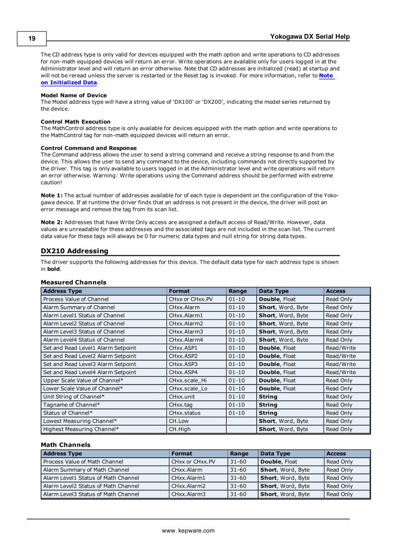
DX210 AddressingThe driver supports the following addresses for this device. The default data type for each address type is shownin bold.
Measured ChannelsAddress Type Format Range Data Type AccessProcess Value of Channel CHxx or CHxx.PV 01-10 Double, Float Read OnlyAlarm Summary of Channel CHxx.Alarm 01-10 Short, Word, Byte Read OnlyAlarm Level1 Status of Channel CHxx.Alarm1 01-10 Short, Word, Byte Read OnlyAlarm Level2 Status of Channel CHxx.Alarm2 01-10 Short, Word, Byte Read OnlyAlarm Level3 Status of Channel CHxx.Alarm3 01-10 Short, Word, Byte Read OnlyAlarm Level4 Status of Channel CHxx.Alarm4 01-10 Short, Word, Byte Read OnlySet and Read Level1 Alarm Setpoint CHxx.ASP1 01-10 Double, Float Read/WriteSet and Read Level2 Alarm Setpoint CHxx.ASP2 01-10 Double, Float Read/WriteSet and Read Level3 Alarm Setpoint CHxx.ASP3 01-10 Double, Float Read/WriteSet and Read Level4 Alarm Setpoint CHxx.ASP4 01-10 Double, Float Read/WriteUpper Scale Value of Channel* CHxx.scale_Hi 01-10 Double, Float Read OnlyLower Scale Value of Channel* CHxx.scale_Lo 01-10 Double, Float Read OnlyUnit String of Channel* CHxx.unit 01-10 String Read OnlyTagname of Channel* CHxx.tag 01-10 String Read OnlyStatus of Channel* CHxx.status 01-10 String Read OnlyLowest Measuring Channel* CH.Low Short, Word, Byte Read OnlyHighest Measuring Channel* CH.High Short, Word, Byte Read Only
Math ChannelsAddress Type Format Range Data Type AccessProcess Value of Math Channel CHxx or CHxx.PV 31-60 Double, Float Read OnlyAlarm Summary of Math Channel CHxx.Alarm 31-60 Short, Word, Byte Read OnlyAlarm Level1 Status of Math Channel CHxx.Alarm1 31-60 Short, Word, Byte Read OnlyAlarm Level2 Status of Math Channel CHxx.Alarm2 31-60 Short, Word, Byte Read OnlyAlarm Level3 Status of Math Channel CHxx.Alarm3 31-60 Short, Word, Byte Read Only
www. kepware.com
19

Yokogawa DX Serial Help
Alarm Level4 Status of Math Channel CHxx.Alarm4 31-60 Short, Word, Byte Read OnlySet and Read Level1 Alarm Setpoint CHxx.ASP1 31-60 Double, Float Read/WriteSet and Read Level2 Alarm Setpoint CHxx.ASP2 31-60 Double, Float Read/WriteSet and Read Level3 Alarm Setpoint CHxx.ASP3 31-60 Double, Float Read/WriteSet and Read Level4 Alarm Setpoint CHxx.ASP4 31-60 Double, Float Read/WriteUpper Scale Value of Math Channel* CHxx.scale_Hi 31-60 Double, Float Read OnlyLower Scale Value of Math Channel* CHxx.scale_Lo 31-60 Double, Float Read OnlyUnit String of Math Channel* CHxx.unit 01-60 String Read OnlyTagname of Math Channel* CHxx.tag 01-60 String Read OnlyStatus of Math Channel* CHxx.status 01-60 String Read OnlyLowest Math Channel* CHA.Low Short,Word, Byte Read OnlyHighest Math Channel* CHA.High Short, Word, Byte Read Only
Initialized DataData associated with the addresses denoted by an (*), are read from the device only at the start of a com-munications session. Once read, the values will not be refreshed until the server has been restarted or the"Reset" tag has been invoked. To invoke a reset, a non-zero value must be written to the Reset tag. Once theReset tag has been invoked the driver will reinitialize all startup data from the device.
Alarm SetpointsData values for Alarm Setpoints that are undefined in the device will be returned as +INF. Data values can only bewritten to Alarm Setpoints that are defined in the device. Write operations to undefined Alarm Setpoints willreturn an error. Write operations are available only for users logged in at the Administrator level and will returnan error otherwise. Alarm setpoint values are read one channel at a time. For devices with a large number of chan-nels, increasing the scan rate of ASP items and/or reducing the number of active ASP items will increase the readperformance of the PV and alarm data.
ScalesData values for Scale_Hi and Scale_Lo for channels that are skipped will be returned as +INF.
Tag NamesFor devices that do not support tag names and channels that have unspecified tag names, the driver will con-struct an internal tag name based on the channel number, for example, the tag name of address 'CH01' will bereturned as 'CH01'.
General Device DataAddress Type Format Range Data Type AccessAdministrator Level* Admin Boolean Read OnlyDate of Last Data Date String Read OnlyTime of Last Data Time String Read OnlyModel Name of Device* Model String Read OnlyMath Communication Data* CDxx 01-30 Float Read/WriteControl Math Execution MathControl Short, Word, Byte Write OnlyReset Alarms AlarmReset Boolean Write OnlyControl Command and Response Command String Read/WritePrevious Screen PreScreen Boolean Write OnlyDirect Reloading of Configuration Reset Boolean Write Only
Administrator LevelThe Admin address type has a value of '1' or 'true' when the user has logged on at the Administrator level and avalue of '0' or 'false' when the user has logged on at the User level.
Math Communication DataThe CD address type is only valid for devices equipped with the math option and write operations to CD addressesfor non-math equipped devices will return an error. Write operations are available only for users logged in at theAdministrator level and will return an error otherwise. Note that CD addresses are initialized (read) at startup andwill not be reread unless the server is restarted or the Reset tag is invoked. For more information, refer toNoteon Initialized Data.
Model Name of DeviceThe Model address type will have a string value of 'DX100' or 'DX200', indicating the model series returned bythe device.
www. kepware.com
20

Yokogawa DX Serial Help
Control Math ExecutionThe MathControl address type is only available for devices equipped with the math option and write operations tothe MathControl tag for non-math equipped devices will return an error.
Control Command and ResponseThe Command address allows the user to send a string command and receive a string response to and from thedevice. This allows the user to send any command to the device, including commands not directly supported bythe driver. This tag is only available to users logged in at the Administrator level and write operations will returnan error otherwise. Warning: Write operations using the Command address should be performed with extremecaution!
Note 1: The actual number of addresses available for of each type is dependent on the configuration of the Yoko-gawa device. If at runtime the driver finds that an address is not present in the device, the driver will post anerror message and remove the tag from its scan list.
Note 2: Addresses that have Write Only access are assigned a default access of Read/Write. However, datavalues are unreadable for these addresses and the associated tags are not included in the scan list. The currentdata value for these tags will always be 0 for numeric data types and null string for string data types.
DX220 AddressingThe driver supports the following addresses for this device. The default data type for each address type is shownin bold.
Measured ChannelsAddress Type Format Range Data Type AccessProcess Value of Channel CHxx or CHxx.PV 01-20 Double, Float Read OnlyAlarm Summary of Channel CHxx.Alarm 01-20 Short, Word, Byte Read OnlyAlarm Level1 Status of Channel CHxx.Alarm1 01-20 Short, Word, Byte Read OnlyAlarm Level2 Status of Channel CHxx.Alarm2 01-20 Short, Word, Byte Read OnlyAlarm Level3 Status of Channel CHxx.Alarm3 01-20 Short, Word, Byte Read OnlyAlarm Level4 Status of Channel CHxx.Alarm4 01-20 Short, Word, Byte Read OnlySet and Read Level1 Alarm Setpoint CHxx.ASP1 01-20 Double, Float Read/WriteSet and Read Level2 Alarm Setpoint CHxx.ASP2 01-20 Double, Float Read/WriteSet and Read Level3 Alarm Setpoint CHxx.ASP3 01-20 Double, Float Read/WriteSet and Read Level4 Alarm Setpoint CHxx.ASP4 01-20 Double, Float Read/WriteUpper Scale Value of Channel* CHxx.scale_Hi 01-20 Double, Float Read OnlyLower Scale Value of Channel* CHxx.scale_Lo 01-20 Double, Float Read OnlyUnit String of Channel* CHxx.unit 01-20 String Read OnlyTagname of Channel* CHxx.tag 01-20 String Read OnlyStatus of Channel* CHxx.status 01-20 String Read OnlyLowest Measuring Channel* CH.Low Short, Word, Byte Read OnlyHighest Measuring Channel* CH.High Short, Word, Byte Read Only
Math ChannelsAddress Type Format Range Data Type AccessProcess Value of Math Channel CHxx or CHxx.PV 31-60 Double, Float Read OnlyAlarm Summary of Math Channel CHxx.Alarm 31-60 Short, Word, Byte Read OnlyAlarm Level1 Status of Math Channel CHxx.Alarm1 31-60 Short, Word, Byte Read OnlyAlarm Level2 Status of Math Channel CHxx.Alarm2 31-60 Short, Word, Byte Read OnlyAlarm Level3 Status of Math Channel CHxx.Alarm3 31-60 Short, Word, Byte Read OnlyAlarm Level4 Status of Math Channel CHxx.Alarm4 31-60 Short, Word, Byte Read OnlySet and Read Level1 Alarm Setpoint CHxx.ASP1 31-60 Double, Float Read/WriteSet and Read Level2 Alarm Setpoint CHxx.ASP2 31-60 Double, Float Read/WriteSet and Read Level3 Alarm Setpoint CHxx.ASP3 31-60 Double, Float Read/WriteSet and Read Level4 Alarm Setpoint CHxx.ASP4 31-60 Double, Float Read/WriteUpper Scale Value of Math Channel* CHxx.scale_Hi 31-60 Double, Float Read OnlyLower Scale Value of Math Channel* CHxx.scale_Lo 31-60 Double, Float Read OnlyUnit String of Math Channel* CHxx.unit 01-60 String Read OnlyTagname of Math Channel* CHxx.tag 01-60 String Read Only
www. kepware.com
21

Yokogawa DX Serial Help
Status of Math Channel* CHxx.status 01-60 String Read OnlyLowest Math Channel* CHA.Low Short,Word, Byte Read OnlyHighest Math Channel* CHA.High Short, Word, Byte Read Only
Initialized DataData associated with the addresses denoted by an (*), are read from the device only at the start of a com-munications session. Once read, the values will not be refreshed until the server has been restarted or the"Reset" tag has been invoked. To invoke a reset, a non-zero value must be written to the Reset tag. Once theReset tag has been invoked the driver will reinitialize all startup data from the device.
Alarm SetpointsData values for Alarm Setpoints that are undefined in the device will be returned as +INF. Data values can only bewritten to Alarm Setpoints that are defined in the device. Write operations to undefined Alarm Setpoints willreturn an error. Write operations are available only for users logged in at the Administrator level and will returnan error otherwise. Alarm setpoint values are read one channel at a time. For devices with a large number of chan-nels, increasing the scan rate of ASP items and/or reducing the number of active ASP items will increase the readperformance of the PV and alarm data.
ScalesData values for Scale_Hi and Scale_Lo for channels that are skipped will be returned as +INF.
Tag NamesFor devices that do not support tag names and channels that have unspecified tag names, the driver will con-struct an internal tag name based on the channel number, for example, the tag name of address 'CH01' will bereturned as 'CH01'.
General Device DataAddress Type Format Range Data Type AccessAdministrator Level* Admin Boolean Read OnlyDate of Last Data Date String Read OnlyTime of Last Data Time String Read OnlyModel Name of Device* Model String Read OnlyMath Communication Data* CDxx 01-30 Float Read/WriteControl Math Execution MathControl Short, Word, Byte Write OnlyReset Alarms AlarmReset Boolean Write OnlyControl Command and Response Command String Read/WritePrevious Screen PreScreen Boolean Write OnlyDirect Reloading of Configuration Reset Boolean Write Only
Administrator LevelThe Admin address type has a value of '1' or 'true' when the user has logged on at the Administrator level and avalue of '0' or 'false' when the user has logged on at the User level.
Math Communication DataThe CD address type is only valid for devices equipped with the math option and write operations to CD addressesfor non-math equipped devices will return an error. Write operations are available only for users logged in at theAdministrator level and will return an error otherwise. Note that CD addresses are initialized (read) at startup andwill not be reread unless the server is restarted or the Reset tag is invoked. For more information, refer toNoteon Initialized Data.
Model Name of DeviceThe Model address type will have a string value of 'DX100' or 'DX200', indicating the model series returned bythe device.
Control Math ExecutionThe MathControl address type is only available for devices equipped with the math option and write operations tothe MathControl tag for non-math equipped devices will return an error.
Control Command and ResponseThe Command address allows the user to send a string command and receive a string response to and from thedevice. This allows the user to send any command to the device, including commands not directly supported bythe driver. This tag is only available to users logged in at the Administrator level and write operations will returnan error otherwise. Warning: Write operations using the Command address should be performed with extremecaution!
www. kepware.com
22
Yokogawa DX Serial Help
Note 1: The actual number of addresses available for of each type is dependent on the configuration of the Yoko-gawa device. If at runtime the driver finds that an address is not present in the device, the driver will post anerror message and remove the tag from its scan list.
Note 2: Addresses that have Write Only access are assigned a default access of Read/Write. However, datavalues are unreadable for these addresses and the associated tags are not included in the scan list. The currentdata value for these tags will always be 0 for numeric data types and null string for string data types.
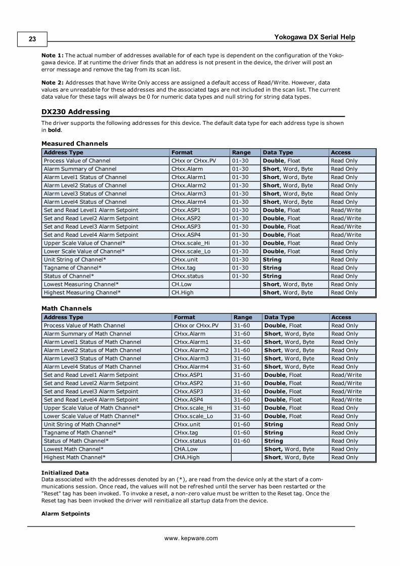
DX230 AddressingThe driver supports the following addresses for this device. The default data type for each address type is shownin bold.
Measured ChannelsAddress Type Format Range Data Type AccessProcess Value of Channel CHxx or CHxx.PV 01-30 Double, Float Read OnlyAlarm Summary of Channel CHxx.Alarm 01-30 Short, Word, Byte Read OnlyAlarm Level1 Status of Channel CHxx.Alarm1 01-30 Short, Word, Byte Read OnlyAlarm Level2 Status of Channel CHxx.Alarm2 01-30 Short, Word, Byte Read OnlyAlarm Level3 Status of Channel CHxx.Alarm3 01-30 Short, Word, Byte Read OnlyAlarm Level4 Status of Channel CHxx.Alarm4 01-30 Short, Word, Byte Read OnlySet and Read Level1 Alarm Setpoint CHxx.ASP1 01-30 Double, Float Read/WriteSet and Read Level2 Alarm Setpoint CHxx.ASP2 01-30 Double, Float Read/WriteSet and Read Level3 Alarm Setpoint CHxx.ASP3 01-30 Double, Float Read/WriteSet and Read Level4 Alarm Setpoint CHxx.ASP4 01-30 Double, Float Read/WriteUpper Scale Value of Channel* CHxx.scale_Hi 01-30 Double, Float Read OnlyLower Scale Value of Channel* CHxx.scale_Lo 01-30 Double, Float Read OnlyUnit String of Channel* CHxx.unit 01-30 String Read OnlyTagname of Channel* CHxx.tag 01-30 String Read OnlyStatus of Channel* CHxx.status 01-30 String Read OnlyLowest Measuring Channel* CH.Low Short, Word, Byte Read OnlyHighest Measuring Channel* CH.High Short, Word, Byte Read Only
Math ChannelsAddress Type Format Range Data Type AccessProcess Value of Math Channel CHxx or CHxx.PV 31-60 Double, Float Read OnlyAlarm Summary of Math Channel CHxx.Alarm 31-60 Short, Word, Byte Read OnlyAlarm Level1 Status of Math Channel CHxx.Alarm1 31-60 Short, Word, Byte Read OnlyAlarm Level2 Status of Math Channel CHxx.Alarm2 31-60 Short, Word, Byte Read OnlyAlarm Level3 Status of Math Channel CHxx.Alarm3 31-60 Short, Word, Byte Read OnlyAlarm Level4 Status of Math Channel CHxx.Alarm4 31-60 Short, Word, Byte Read OnlySet and Read Level1 Alarm Setpoint CHxx.ASP1 31-60 Double, Float Read/WriteSet and Read Level2 Alarm Setpoint CHxx.ASP2 31-60 Double, Float Read/WriteSet and Read Level3 Alarm Setpoint CHxx.ASP3 31-60 Double, Float Read/WriteSet and Read Level4 Alarm Setpoint CHxx.ASP4 31-60 Double, Float Read/WriteUpper Scale Value of Math Channel* CHxx.scale_Hi 31-60 Double, Float Read OnlyLower Scale Value of Math Channel* CHxx.scale_Lo 31-60 Double, Float Read OnlyUnit String of Math Channel* CHxx.unit 01-60 String Read OnlyTagname of Math Channel* CHxx.tag 01-60 String Read OnlyStatus of Math Channel* CHxx.status 01-60 String Read OnlyLowest Math Channel* CHA.Low Short,Word, Byte Read OnlyHighest Math Channel* CHA.High Short, Word, Byte Read Only
Initialized DataData associated with the addresses denoted by an (*), are read from the device only at the start of a com-munications session. Once read, the values will not be refreshed until the server has been restarted or the"Reset" tag has been invoked. To invoke a reset, a non-zero value must be written to the Reset tag. Once theReset tag has been invoked the driver will reinitialize all startup data from the device.
Alarm Setpoints
www. kepware.com
23

Yokogawa DX Serial Help
Data values for Alarm Setpoints that are undefined in the device will be returned as +INF. Data values can only bewritten to Alarm Setpoints that are defined in the device. Write operations to undefined Alarm Setpoints willreturn an error. Write operations are available only for users logged in at the Administrator level and will returnan error otherwise. Alarm setpoint values are read one channel at a time. For devices with a large number of chan-nels, increasing the scan rate of ASP items and/or reducing the number of active ASP items will increase the readperformance of the PV and alarm data.
ScalesData values for Scale_Hi and Scale_Lo for channels that are skipped will be returned as +INF.
Tag NamesFor devices that do not support tag names and channels that have unspecified tag names, the driver will con-struct an internal tag name based on the channel number, for example, the tag name of address 'CH01' will bereturned as 'CH01'.
General Device DataAddress Type Format Range Data Type AccessAdministrator Level* Admin Boolean Read OnlyDate of Last Data Date String Read OnlyTime of Last Data Time String Read OnlyModel Name of Device* Model String Read OnlyMath Communication Data* CDxx 01-30 Float Read/WriteControl Math Execution MathControl Short, Word, Byte Write OnlyReset Alarms AlarmReset Boolean Write OnlyControl Command and Response Command String Read/WritePrevious Screen PreScreen Boolean Write OnlyDirect Reloading of Configuration Reset Boolean Write Only
Administrator LevelThe Admin address type has a value of '1' or 'true' when the user has logged on at the Administrator level and avalue of '0' or 'false' when the user has logged on at the User level.
Math Communication DataThe CD address type is only valid for devices equipped with the math option and write operations to CD addressesfor non-math equipped devices will return an error. Write operations are available only for users logged in at theAdministrator level and will return an error otherwise. Note that CD addresses are initialized (read) at startup andwill not be reread unless the server is restarted or the Reset tag is invoked. For more information, refer toNoteon Initialized Data.
Model Name of DeviceThe Model address type will have a string value of 'DX100' or 'DX200', indicating the model series returned bythe device.
Control Math ExecutionThe MathControl address type is only available for devices equipped with the math option and write operations tothe MathControl tag for non-math equipped devices will return an error.
Control Command and ResponseThe Command address allows the user to send a string command and receive a string response to and from thedevice. This allows the user to send any command to the device, including commands not directly supported bythe driver. This tag is only available to users logged in at the Administrator level and write operations will returnan error otherwise. Warning: Write operations using the Command address should be performed with extremecaution!
Note 1: The actual number of addresses available for of each type is dependent on the configuration of the Yoko-gawa device. If at runtime the driver finds that an address is not present in the device, the driver will post anerror message and remove the tag from its scan list.
Note 2: Addresses that have Write Only access are assigned a default access of Read/Write. However, datavalues are unreadable for these addresses and the associated tags are not included in the scan list. The currentdata value for these tags will always be 0 for numeric data types and null string for string data types.
www. kepware.com
24
Yokogawa DX Serial Help
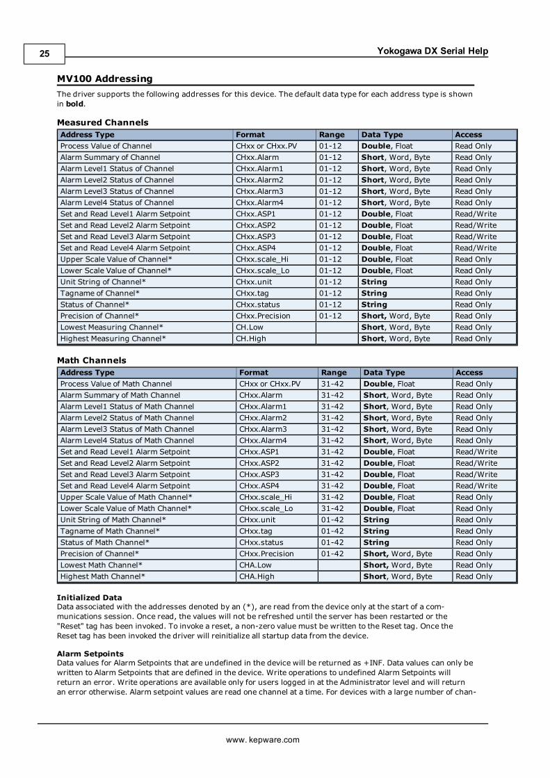
MV100 AddressingThe driver supports the following addresses for this device. The default data type for each address type is shownin bold.
Measured ChannelsAddress Type Format Range Data Type AccessProcess Value of Channel CHxx or CHxx.PV 01-12 Double, Float Read OnlyAlarm Summary of Channel CHxx.Alarm 01-12 Short, Word, Byte Read OnlyAlarm Level1 Status of Channel CHxx.Alarm1 01-12 Short, Word, Byte Read OnlyAlarm Level2 Status of Channel CHxx.Alarm2 01-12 Short, Word, Byte Read OnlyAlarm Level3 Status of Channel CHxx.Alarm3 01-12 Short, Word, Byte Read OnlyAlarm Level4 Status of Channel CHxx.Alarm4 01-12 Short, Word, Byte Read OnlySet and Read Level1 Alarm Setpoint CHxx.ASP1 01-12 Double, Float Read/WriteSet and Read Level2 Alarm Setpoint CHxx.ASP2 01-12 Double, Float Read/WriteSet and Read Level3 Alarm Setpoint CHxx.ASP3 01-12 Double, Float Read/WriteSet and Read Level4 Alarm Setpoint CHxx.ASP4 01-12 Double, Float Read/WriteUpper Scale Value of Channel* CHxx.scale_Hi 01-12 Double, Float Read OnlyLower Scale Value of Channel* CHxx.scale_Lo 01-12 Double, Float Read OnlyUnit String of Channel* CHxx.unit 01-12 String Read OnlyTagname of Channel* CHxx.tag 01-12 String Read OnlyStatus of Channel* CHxx.status 01-12 String Read OnlyPrecision of Channel* CHxx.Precision 01-12 Short,Word, Byte Read OnlyLowest Measuring Channel* CH.Low Short, Word, Byte Read OnlyHighest Measuring Channel* CH.High Short, Word, Byte Read Only
Math ChannelsAddress Type Format Range Data Type AccessProcess Value of Math Channel CHxx or CHxx.PV 31-42 Double, Float Read OnlyAlarm Summary of Math Channel CHxx.Alarm 31-42 Short, Word, Byte Read OnlyAlarm Level1 Status of Math Channel CHxx.Alarm1 31-42 Short, Word, Byte Read OnlyAlarm Level2 Status of Math Channel CHxx.Alarm2 31-42 Short, Word, Byte Read OnlyAlarm Level3 Status of Math Channel CHxx.Alarm3 31-42 Short, Word, Byte Read OnlyAlarm Level4 Status of Math Channel CHxx.Alarm4 31-42 Short, Word, Byte Read OnlySet and Read Level1 Alarm Setpoint CHxx.ASP1 31-42 Double, Float Read/WriteSet and Read Level2 Alarm Setpoint CHxx.ASP2 31-42 Double, Float Read/WriteSet and Read Level3 Alarm Setpoint CHxx.ASP3 31-42 Double, Float Read/WriteSet and Read Level4 Alarm Setpoint CHxx.ASP4 31-42 Double, Float Read/WriteUpper Scale Value of Math Channel* CHxx.scale_Hi 31-42 Double, Float Read OnlyLower Scale Value of Math Channel* CHxx.scale_Lo 31-42 Double, Float Read OnlyUnit String of Math Channel* CHxx.unit 01-42 String Read OnlyTagname of Math Channel* CHxx.tag 01-42 String Read OnlyStatus of Math Channel* CHxx.status 01-42 String Read OnlyPrecision of Channel* CHxx.Precision 01-42 Short,Word, Byte Read OnlyLowest Math Channel* CHA.Low Short,Word, Byte Read OnlyHighest Math Channel* CHA.High Short, Word, Byte Read Only
Initialized DataData associated with the addresses denoted by an (*), are read from the device only at the start of a com-munications session. Once read, the values will not be refreshed until the server has been restarted or the"Reset" tag has been invoked. To invoke a reset, a non-zero value must be written to the Reset tag. Once theReset tag has been invoked the driver will reinitialize all startup data from the device.
Alarm SetpointsData values for Alarm Setpoints that are undefined in the device will be returned as +INF. Data values can only bewritten to Alarm Setpoints that are defined in the device. Write operations to undefined Alarm Setpoints willreturn an error. Write operations are available only for users logged in at the Administrator level and will returnan error otherwise. Alarm setpoint values are read one channel at a time. For devices with a large number of chan-
www. kepware.com
25

Yokogawa DX Serial Help
nels, increasing the scan rate of ASP items and/or reducing the number of active ASP items will increase the readperformance of the PV and alarm data.
ScalesData values for Scale_Hi and Scale_Lo for channels that are skipped will be returned as +INF.
Tag NamesFor devices that do not support tag names and channels that have unspecified tag names, the driver will con-struct an internal tag name based on the channel number, for example, the tag name of address 'CH01' will bereturned as 'CH01'.
General Device DataAddress Type Format Range Data Type AccessAdministrator Level* Admin Boolean Read OnlyDate of Last Data Date String Read OnlyTime of Last Data Time String Read OnlyModel Name of Device* Model String Read OnlyMath Communication Data* CDxx 01-30 Float Read/WriteControl Math Execution MathControl Short, Word, Byte Write OnlyReset Alarms AlarmReset Boolean Write OnlyControl Command and Response Command String Read/WritePrevious Screen PreScreen Boolean Write OnlyDirect Reloading of Configuration Reset Boolean Write Only
Administrator LevelThe Admin address type has a value of '1' or 'true' when the user has logged on at the Administrator level and avalue of '0' or 'false' when the user has logged on at the User level.
Math Communication DataThe CD address type is only valid for devices equipped with the math option and write operations to CD addressesfor non-math equipped devices will return an error. Write operations are available only for users logged in at theAdministrator level and will return an error otherwise. Note that CD addresses are initialized (read) at startup andwill not be reread unless the server is restarted or the Reset tag is invoked. For more information, refer toNoteon Initialized Data.
Model Name of DeviceThe Model address type will have a string value of 'DX100' or 'DX200', indicating the model series returned bythe device.
Control Math ExecutionThe MathControl address type is only available for devices equipped with the math option and write operations tothe MathControl tag for non-math equipped devices will return an error.
Control Command and ResponseThe Command address allows the user to send a string command and receive a string response to and from thedevice. This allows the user to send any command to the device, including commands not directly supported bythe driver. This tag is only available to users logged in at the Administrator level and write operations will returnan error otherwise. Warning: Write operations using the Command address should be performed with extremecaution!
Note 1: The actual number of addresses available for of each type is dependent on the configuration of the Yoko-gawa device. If at runtime the driver finds that an address is not present in the device, the driver will post anerror message and remove the tag from its scan list.
Note 2: Addresses that have Write Only access are assigned a default access of Read/Write. However, datavalues are unreadable for these addresses and the associated tags are not included in the scan list. The currentdata value for these tags will always be 0 for numeric data types and null string for string data types.
MV200 AddressingThe driver supports the following addresses for this device. The default data type for each address type is shownin bold.
Measured Channels
www. kepware.com
26

Yokogawa DX Serial Help
Address Type Format Range Data Type AccessProcess Value of Channel CHxx or CHxx.PV 01-30 Double, Float Read OnlyAlarm Summary of Channel CHxx.Alarm 01-30 Short, Word, Byte Read OnlyAlarm Level1 Status of Channel CHxx.Alarm1 01-30 Short, Word, Byte Read OnlyAlarm Level2 Status of Channel CHxx.Alarm2 01-30 Short, Word, Byte Read OnlyAlarm Level3 Status of Channel CHxx.Alarm3 01-30 Short, Word, Byte Read OnlyAlarm Level4 Status of Channel CHxx.Alarm4 01-30 Short, Word, Byte Read OnlySet and Read Level1 Alarm Setpoint CHxx.ASP1 01-30 Double, Float Read/WriteSet and Read Level2 Alarm Setpoint CHxx.ASP2 01-30 Double, Float Read/WriteSet and Read Level3 Alarm Setpoint CHxx.ASP3 01-30 Double, Float Read/WriteSet and Read Level4 Alarm Setpoint CHxx.ASP4 01-30 Double, Float Read/WriteUpper Scale Value of Channel* CHxx.scale_Hi 01-30 Double, Float Read OnlyLower Scale Value of Channel* CHxx.scale_Lo 01-30 Double, Float Read OnlyUnit String of Channel* CHxx.unit 01-30 String Read OnlyTagname of Channel* CHxx.tag 01-30 String Read OnlyStatus of Channel* CHxx.status 01-30 String Read OnlyPrecision of Channel* CHxx.Precision 01-30 Short,Word, Byte Read OnlyLowest Measuring Channel* CH.Low Short, Word, Byte Read OnlyHighest Measuring Channel* CH.High Short, Word, Byte Read Only
Math ChannelsAddress Type Format Range Data Type AccessProcess Value of Math Channel CHxx or CHxx.PV 31-60 Double, Float Read OnlyAlarm Summary of Math Channel CHxx.Alarm 31-60 Short, Word, Byte Read OnlyAlarm Level1 Status of Math Channel CHxx.Alarm1 31-60 Short, Word, Byte Read OnlyAlarm Level2 Status of Math Channel CHxx.Alarm2 31-60 Short, Word, Byte Read OnlyAlarm Level3 Status of Math Channel CHxx.Alarm3 31-60 Short, Word, Byte Read OnlyAlarm Level4 Status of Math Channel CHxx.Alarm4 31-60 Short, Word, Byte Read OnlySet and Read Level1 Alarm Setpoint CHxx.ASP1 31-60 Double, Float Read/WriteSet and Read Level2 Alarm Setpoint CHxx.ASP2 31-60 Double, Float Read/WriteSet and Read Level3 Alarm Setpoint CHxx.ASP3 31-60 Double, Float Read/WriteSet and Read Level4 Alarm Setpoint CHxx.ASP4 31-60 Double, Float Read/WriteUpper Scale Value of Math Channel* CHxx.scale_Hi 31-60 Double, Float Read OnlyLower Scale Value of Math Channel* CHxx.scale_Lo 31-60 Double, Float Read OnlyUnit String of Math Channel* CHxx.unit 01-60 String Read OnlyTagname of Math Channel* CHxx.tag 01-60 String Read OnlyStatus of Math Channel* CHxx.status 01-60 String Read OnlyPrecision of Channel* CHxx.Precision 01-60 Short,Word, Byte Read OnlyLowest Math Channel* CHA.Low Short,Word, Byte Read OnlyHighest Math Channel* CHA.High Short, Word, Byte Read Only
Initialized DataData associated with the addresses denoted by an (*), are read from the device only at the start of a com-munications session. Once read, the values will not be refreshed until the server has been restarted or the"Reset" tag has been invoked. To invoke a reset, a non-zero value must be written to the Reset tag. Once theReset tag has been invoked the driver will reinitialize all startup data from the device.
Alarm SetpointsData values for Alarm Setpoints that are undefined in the device will be returned as +INF. Data values can only bewritten to Alarm Setpoints that are defined in the device. Write operations to undefined Alarm Setpoints willreturn an error. Write operations are available only for users logged in at the Administrator level and will returnan error otherwise. Alarm setpoint values are read one channel at a time. For devices with a large number of chan-nels, increasing the scan rate of ASP items and/or reducing the number of active ASP items will increase the readperformance of the PV and alarm data.
ScalesData values for Scale_Hi and Scale_Lo for channels that are skipped will be returned as +INF.
Tag Names
www. kepware.com
27

Yokogawa DX Serial Help
For devices that do not support tag names and channels that have unspecified tag names, the driver will con-struct an internal tag name based on the channel number, for example, the tag name of address 'CH01' will bereturned as 'CH01'.
General Device DataAddress Type Format Range Data Type AccessAdministrator Level* Admin Boolean Read OnlyDate of Last Data Date String Read OnlyTime of Last Data Time String Read OnlyModel Name of Device* Model String Read OnlyMath Communication Data* CDxx 01-30 Float Read/WriteControl Math Execution MathControl Short, Word, Byte Write OnlyReset Alarms AlarmReset Boolean Write OnlyControl Command and Response Command String Read/WritePrevious Screen PreScreen Boolean Write OnlyDirect Reloading of Configuration Reset Boolean Write Only
Administrator LevelThe Admin address type has a value of '1' or 'true' when the user has logged on at the Administrator level and avalue of '0' or 'false' when the user has logged on at the User level.
Math Communication DataThe CD address type is only valid for devices equipped with the math option and write operations to CD addressesfor non-math equipped devices will return an error. Write operations are available only for users logged in at theAdministrator level and will return an error otherwise. Note that CD addresses are initialized (read) at startup andwill not be reread unless the server is restarted or the Reset tag is invoked. For more information, refer toNoteon Initialized Data.
Model Name of DeviceThe Model address type will have a string value of 'DX100' or 'DX200', indicating the model series returned bythe device.
Control Math ExecutionThe MathControl address type is only available for devices equipped with the math option and write operations tothe MathControl tag for non-math equipped devices will return an error.
Control Command and ResponseThe Command address allows the user to send a string command and receive a string response to and from thedevice. This allows the user to send any command to the device, including commands not directly supported bythe driver. This tag is only available to users logged in at the Administrator level and write operations will returnan error otherwise. Warning: Write operations using the Command address should be performed with extremecaution!
Note 1: The actual number of addresses available for of each type is dependent on the configuration of the Yoko-gawa device. If at runtime the driver finds that an address is not present in the device, the driver will post anerror message and remove the tag from its scan list.
Note 2: Addresses that have Write Only access are assigned a default access of Read/Write. However, datavalues are unreadable for these addresses and the associated tags are not included in the scan list. The currentdata value for these tags will always be 0 for numeric data types and null string for string data types.
www. kepware.com
28

Yokogawa DX Serial Help
Automatic Tag Database GenerationThe automatic OPC tag database generation features of this driver have been designed to make the setting up theOPC application a Plug and Play operation. This driver can be configured to automatically build a list of OPC tagswithin the OPC Server that correspond to device specific data. The automatically generated OPC tags can then bebrowsed from the OPC client. The OPC tags that are generated depends on the nature of the driver.
If the target device supports its own local tag database the driver will read the device's tag information and usethis data to generate OPC tags within the OPC Server. If the device does not natively support its own named tags,the driver will create a list of tags based on information specific to the driver. An example of these two conditionsmay be as follows:
1. A data acquisition system that supports its own local tag database. The driver will use the tags names found inthe device to build the OPC Server's OPC tags.
2. An Ethernet I/O system that supports detection of I/O module type. The driver in this case will automaticallygenerate OPC tags in the OPC Server that are based on the types of I/O modules plugged into the Ethernet I/Orack.
The mode of operation for automatic tag database generation is completely configurable. The following dialog isused to configure how the OPC Server and the associated communications driver will handle automatic OPC tagdatabase generation.
Automatic tag database generation on device startup is used to configure when OPC tags will be auto-matically generated. There are three possible selections:
l Do not generate on startup, the default condition, prevents the driver from adding any OPC tags to tagspace of the OPC Server.
l Always generate on startup causes the driver to always evaluate the device for tag information and toadd OPC tags to the tag space of the server each time the server is launched.
l Generate on first startup causes the driver to evaluate the target device for tag information the firsttime this OPC Server project is run and to add any OPC tags to the server tag space as needed.
When the automatic generation of OPC tags is selected, any tags that are added to the server's tag space must besaved with the project. The OPC Server project can be configured to auto save from the Tools|Optionsmenu.
When automatic tag generation is enabled, the server needs to know what to do with OPC tags that it may haveadded from a previous run or with OPC tags that have been added or modified after the communications driveradded them. Perform the following action is used to control how the server will handle OPC tags that wereautomatically generated and currently exist in the OPC Server project. This feature prevents automatically
www. kepware.com
29

Yokogawa DX Serial Help
generated tags from piling up in the server. This would occur if, using the Ethernet I/O example above, you con-tinued to change the I/O modules in the rack with the OPC Server configured to always generate new OPC tags onstartup. Under this condition every time the communications driver detected a new I/O module, the tags wouldbe added to the server. If the old tags are not removed, a number of unused tags could accumulate in theserver's tag space. Perform the following action is used to tailor the server's operation to best fit the appli-cation's needs. Descriptions of the selections are as follows:
1. Delete on create, the default condition, allows the server to remove any tags that had previous beenadded to the tag space before the communications driver can add any new tags.
2. Overwrite as necessary allows the server to remove only tags the communications driver is replacingwith new tags. Any tags that are not being overwritten will remain in the server's tag space.
3. Do not overwrite prevents the server from removing any tags that had been previous generated or mayhave already existed in the server. With this selection, the communications driver can only add tags thatare completely new.
4. Do not overwrite, log error has the same effect as the third with the addition: an error message will beposted to the OPC Server's event log when a tag overwrite would have occurred.
Note: Removing OPC tags affects tags that have been automatically generated by the communications driver andany tags that have been added using names that match generated tags. We recommend that users avoid addingtags to the server using names that match tags that may be automatically generated by the driver.
The parameter Add generated tags to the following group can be used to keep automatically generated tagsfrommixing with tags that have been entered manually. This parameter specifies a sub group that will be usedwhen adding all automatically generated tags for this device. The name of the sub group can be up to 31 char-acters in length. The following displays demonstrate how this parameter affects where automatically generatedtags are placed in the server's tag space. As shown below, this parameter provides a root branch to which allautomatically generated tags will be added.
No sub group specified.
www. kepware.com
30

Yokogawa DX Serial Help
Sub group named MyGroup specified.
The Auto Create button can be used to manually initiate the creation of automatically generated OPC tags. Itforces the communications driver to reevaluate the device for possible tag changes after the device's con-figuration has been modified. Auto Create can also be accessed from System Tags, in order to have the deviceallow the OPC client application to initiate tag database creation.
www. kepware.com
31

Yokogawa DX Serial Help
Error DescriptionsThe following error/warning messages may be generated. Click on the link for a description of the message.
Address ValidationMissing addressDevice address '<address>' contains a syntax errorAddress '<address>' is out of range for the specified device or registerData Type '<type>' is not valid for device address '<address>'Device address '<address>' is Read Only
Serial CommunicationsCOMn does not existError opening COMnCOMn is in use by another applicationUnable to set comm parameters on COMnCommunications error on '<channel name>' [<error mask>]
Device Status MessagesDevice '<device name>' is not respondingUnable to write to '<address>' on device '<device name>
Address ValidationThe following error/warning messages may be generated. Click on the link for a description of the message.
Address ValidationMissing addressDevice address '<address>' contains a syntax errorAddress '<address>' is out of range for the specified device or registerData Type '<type>' is not valid for device address '<address>'Device address '<address>' is Read Only
Missing addressError Type:Warning
Possible Cause:A tag address that has been specified dynamically has no length.
Solution:Re-enter the address in the client application.
Device address '<address>' contains a syntax errorError Type:Warning
Possible Cause:A tag address that has been specified dynamically contains one or more invalid characters.
Solution:Re-enter the address in the client application.
Address '<address>' is out of range for the specified device or registerError Type:Warning
Possible Cause:A tag address that has been specified dynamically references a location that is beyond the range of supportedlocations for the device.
www. kepware.com
32
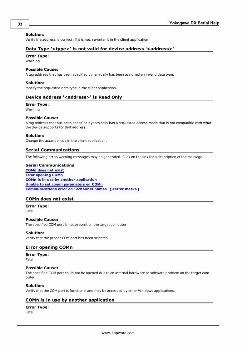
Yokogawa DX Serial Help
Solution:Verify the address is correct; if it is not, re-enter it in the client application.
Data Type '<type>' is not valid for device address '<address>'Error Type:Warning
Possible Cause:A tag address that has been specified dynamically has been assigned an invalid data type.
Solution:Modify the requested data type in the client application.
Device address '<address>' is Read OnlyError Type:Warning
Possible Cause:A tag address that has been specified dynamically has a requested access mode that is not compatible with whatthe device supports for that address.
Solution:Change the access mode in the client application.
Serial CommunicationsThe following error/warning messages may be generated. Click on the link for a description of the message.
Serial CommunicationsCOMn does not existError opening COMnCOMn is in use by another applicationUnable to set comm parameters on COMnCommunications error on '<channel name>' [<error mask>]
COMn does not existError Type:Fatal
Possible Cause:The specified COM port is not present on the target computer.
Solution:Verify that the proper COM port has been selected.
Error opening COMnError Type:Fatal
Possible Cause:The specified COM port could not be opened due to an internal hardware or software problem on the target com-puter.
Solution:Verify that the COM port is functional and may be accessed by other Windows applications.
COMn is in use by another applicationError Type:Fatal
www. kepware.com
33

Yokogawa DX Serial Help
Possible Cause:The serial port assigned to a device is being used by another application.
Solution:1. Verify that the correct port has been assigned to the channel.2. Verify that only one copy of the current project is running.
Unable to set comm parameters on COMnError Type:Fatal
Possible Cause:The serial parameters for the specified COM port are not valid.
Solution:Verify the serial parameters and make any necessary changes.
Communications error on '<channel name>' [<error mask>]Error Type:Serious
Error Mask Definitions:B = Hardware break detected.F = Framing error.E = I/O error.O = Character buffer overrun.R = RX buffer overrun.P = Received byte parity error.T = TX buffer full.
Possible Cause:1. The serial connection between the device and the host PC is bad.2. The communications parameters for the serial connection are incorrect.
Solution:1. Verify the cabling between the PC and the PLC device.2. Verify that the specified communications parameters match those of the device.
Device Status MessagesThe following error/warning messages may be generated. Click on the link for a description of the message.
Device Status MessagesDevice '<device name>' is not respondingUnable to write to '<address>' on device '<device name>
Device '<device name>' is not respondingError Type:Serious
Possible Cause:1. The connection between the device and the host PC is broken.2. The IP address assigned to the device is incorrect.3. The connection cannot be established in the specified timeout period.4. The response from the device took longer to receive than the amount of time specified in the "Request Timeout"device setting.
Solution:1. Verify the cabling between the PC and the PLC device.2. Verify the IP address given to the named device matches that of the actual device.3. Increase the Connect Timeout value in the Timeout page of Device Properties.4. Increase the Request Timeout setting so that the entire response can be handled.
www. kepware.com
34
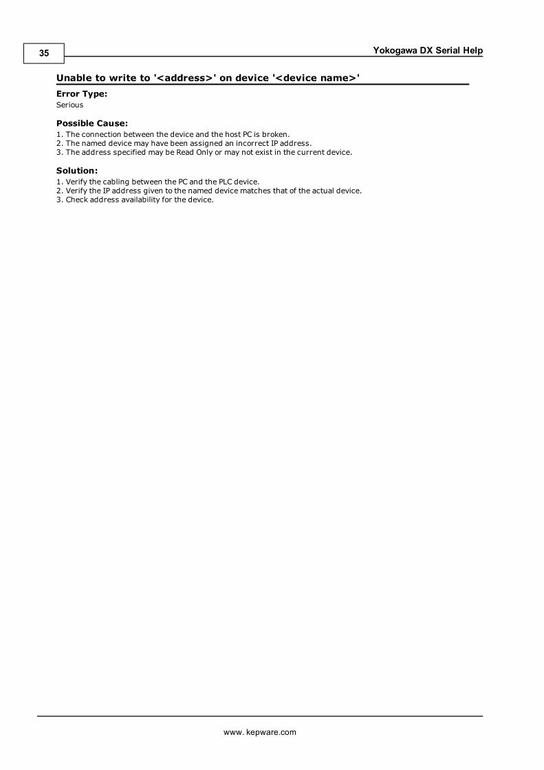
Yokogawa DX Serial Help
Unable to write to '<address>' on device '<device name>'Error Type:Serious
Possible Cause:1. The connection between the device and the host PC is broken.2. The named device may have been assigned an incorrect IP address.3. The address specified may be Read Only or may not exist in the current device.
Solution:1. Verify the cabling between the PC and the PLC device.2. Verify the IP address given to the named device matches that of the actual device.3. Check address availability for the device.
www. kepware.com
35

Yokogawa DX Serial Help
Index
A
Address '<address>' is out of range for the specified device or register 32Address Descriptions 8Address Validation 32Automatic Tag Database Generation 29
B
BCD 7Boolean 7
C
Communications error on '<channel name>' [<error mask>] 34COMn does not exist 33COMn is in use by another application 33
D
Data Type '<type>' is not valid for device address '<address>' 33Data Types Description 7Device '<device name>' is not responding 34Device address '<address>' contains a syntax error 32Device address '<address>' is Read Only 33Device ID 4Device Setup 4Device Status Messages 34DWord 7DX102 Addressing 8DX104 Addressing 10DX106 Addressing 12DX112 Addressing 13DX204 Addressing 15
www. kepware.com
36

Yokogawa DX Serial Help
DX208 Addressing 17DX210 Addressing 19DX220 Addressing 21DX230 Addressing 23
E
Error Descriptions 32Error opening COMn 33
F
Float 7
L
LBCD 7Long 7
M
Missing address 32Modem Setup 6MV100 Addressing 25MV200 Addressing 26
N
Network 4
O
Overview 3
www. kepware.com
37
Yokogawa DX Serial Help
S
Serial Communications 33Short 7
U
Unable to set comm parameters on COMn 34Unable to write tag '<address>' on device '<device name>' 35
W
Word 7
www. kepware.com
38