Embed Size (px)
Citation preview

1
CYLINDERS
Clippard Instrument Laboratory, Inc. (513) 521-4261 www.clippard.com
STAINLESS STEEL CYLINDERS 2
CORROSION RESISTANT CYLINDERS 62
AIR FORCE ONE COMPACT CYLINDERS 70
MINIMATIC® CYLINDERS 82

STAINLESS STEEL CYLINDER CONSTRUCTION
2 Clippard Instrument Laboratory, Inc. (513) 521-4261 www.clippard.com
Extra rod length for greaterthread engagement and
adjustment
Sinteredbronze rod
bushing
Long life “U” cuprod seals
Piston rod joint is threaded andbonded for extra strength
Drilled relief holes for fullpiston area breakaway
Anodized heads
Sintered bronze bushing on clevisand universal mount cylinders
Long life “U”cup piston seals
304 stainlesssteel body
303 stainless steel rod,ground, polished and rollerburnished for a hard, mirror finish
Wrench flats toaid in installation
In the early 1950’s, Clippard introduced miniature pneumatic cylinders and valves to industry. No othermanufacturer can boast of the same experience or knowledge of miniature components.
Air cylinders have always been an integral part of the Clippard Minimatic® line. Over the years Clippardhas responded to requests from cylinder users to provide additional sizes of air cylinders and auxiliarysupport products. While competitively priced, these products maintain the Clippard standard for quality andreliability that has been the industry standard for many years.
Features• Polished ID 304 stainless steel tubes for low breakaway
• Precision rolled construction for a solid, leakproofcylinder at a reasonable price
• Machined aluminum heads are clear anodizedfor extra protection against corrosion
• Cylinder heads are machined from oneside for better concentricity
• Sintered bronze rod bushing
• Sintered bronze clevis bushing on allclevis and universal mount cylinders
• Rods are threaded and bonded to pistons
• Ground, polished and roller burnished 303 stainlessrods provide a smoother rod finish that protects rodseals, giving longer life
• Full piston area breakaway to assure fullpower from the beginning of each stroke
• Buna-N “U”-cup piston seals for full power,low friction and trouble-free performance
• Buna-N “U”-cup rod seals for leakproof operation
• Temperature range: -32˚F to 230˚F
• Maximum pressure: 250 psig

F
P A
3
STAINLESS STEEL CYLINDER
Clippard Instrument Laboratory, Inc. (513) 521-4261 www.clippard.com
❑ ❑ ❑ - ❑ - ❑ - ❑
Cylinder TypeD - Double ActingS - Single ActingR - Reverse ActingF - Front Spring BiasB - Back Spring Bias
Rod TypeD - Double Ended RodR - Rotating RodN - Non-Rotating RodH - Hollow Rod
Bore 05 - 5/16”08 - 1/210 - 5/8”12 - 3/4”14 - 7/8”17 - 1 1/16”20 - 1 1/4”24 - 1 1/2”28 - 1 3/4”32 - 2”40 - 2 1/2”48 - 3”
StrokeIn inches & fractions of an inch
OptionsB - BumpersV - Viton® SealsC - CushionsMB - Magnetic Piston for Hall Effect
sensors (includes bumpers)F - Cushion Front EndR - Cushion Rear EndW - Rod WiperS - Side PortedH - Heavy SpringP - Rotated Ports
Mounting TypeS - StudU - UniversalC - ClevisF - Front BlockE - End StudT - Trunnion
NUMBERING SYSTEM
SPECIFICATIONS
30
25
20
15
10
5
0
5/16
5/16
5/
16
1/2
5/8
7/8
1 1/
16
1 1/
4
1 1/
2
1 3/
4
3/4 2
2 1/
2
STAINLESS STEEL CYLINDERSTANDARD & HEAVY SPRING FORCES
bore
Bore 5/16 1/2 5/8 3/4 7/8 1-1/16 1-1/4 1-1/2 1-3/4 2 2-1/2
At Rest .5 .9 1.3 3.0 3.0 2.0 4.5 4.5 11.0 15.0 15.0
Compressed 1.0 2.0 4.0 6.0 6.0 7.0 10.0 10.0 24.0 30.0 30.0
Bore 5/16 1/2 5/8 3/4 7/8 1-1/16 1-1/4 1-1/2 1-3/4 2 2-1/2
At Rest N/A 2.0 3.3 5.0 5.0 5.5 8.5 8.5 N/A N/A N/A
Compressed N/A 4.0 9.0 10.0 10.0 13.0 17.0 17.0 N/A N/A N/A
The force required, operating airpressure and cylinder bore are allfactors that must be determined orknown when sizing an air cylinder.If two are known the other is easilycalculated per the formulas andtriangle shown below.
F - Force or load in pounds F = P x AP - Pressure P = F / AA - Area of cylinder A = F / P
(square inches)
Area is derived using either of the followingformulas: Diameter 2 x .7854 or Radius 2 x π
Bore Size5/16 1/2 5/8 3/4 7/8 1-1/16 1-1/4 1-1/2 1-3/4 2 2-1/2 3
Force Factor - Extend (Area).07 .19 .31 .44 .60 .88 1.2 1.7 2.4 3.1 4.9 7.0
Rod Size1/8 3/16 3/16 1/4 1/4 5/16 3/8 7/16 1/2 5/8 5/8 3/4
Rod Area.01 .03 .03 .05 .05 .08 .11 .15 .20 .31 .31 .44
Force Factor - Retract (Area).06 .16 .28 .39 .55 .80 1.09 1.55 2.20 2.90 4.59 6.56
Standard Spring Forces (lbs)
Heavy Spring Forces (lbs)
Not all combinations are available - consult factory
lbs.
STAINLESS STEEL CYLINDER
4 Clippard Instrument Laboratory, Inc. (513) 521-4261 www.clippard.com
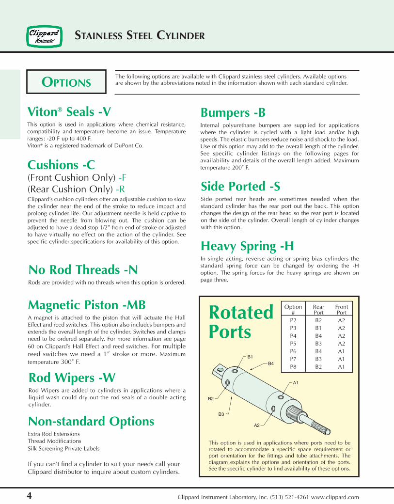
Magnetic Piston -MBA magnet is attached to the piston that will actuate the HallEffect and reed switches. This option also includes bumpers andextends the overall length of the cylinder. Switches and clampsneed to be ordered separately. For more information see page60 on Clippard’s Hall Effect and reed switches. For multiplereed switches we need a 1” stroke or more. Maximumtemperature 300˚ F.
Viton® Seals -VThis option is used in applications where chemical resistance,compatibility and temperature become an issue. Temperatureranges: -20 F up to 400 F. Viton® is a registered trademark of DuPont Co.
Bumpers -BInternal polyurethane bumpers are supplied for applicationswhere the cylinder is cycled with a light load and/or highspeeds. The elastic bumpers reduce noise and shock to the load.Use of this option may add to the overall length of the cylinder.See specific cylinder listings on the following pages foravailability and details of the overall length added. Maximumtemperature 200˚ F.
OPTIONS
Cushions -C(Front Cushion Only) -F(Rear Cushion Only) -R Clippard’s cushion cylinders offer an adjustable cushion to slowthe cylinder near the end of the stroke to reduce impact andprolong cylinder life. Our adjustment needle is held captive toprevent the needle from blowing out. The cushion can beadjusted to have a dead stop 1/2” from end of stroke or adjustedto have virtually no effect on the action of the cylinder. Seespecific cylinder specifications for availability of this option.
The following options are available with Clippard stainless steel cylinders. Available optionsare shown by the abbreviations noted in the information shown with each standard cylinder.
Rod Wipers -WRod Wipers are added to cylinders in applications where aliquid wash could dry out the rod seals of a double actingcylinder.
No Rod Threads -NRods are provided with no threads when this option is ordered.
Side Ported -SSide ported rear heads are sometimes needed when thestandard cylinder has the rear port out the back. This optionchanges the design of the rear head so the rear port is locatedon the side of the cylinder. Overall length of cylinder changeswith this option.
Heavy Spring -HIn single acting, reverse acting or spring bias cylinders thestandard spring force can be changed by ordering the -Hoption. The spring forces for the heavy springs are shown onpage three.
Non-standard OptionsExtra Rod ExtensionsThread ModificationsSilk Screening Private Labels
If you can’t find a cylinder to suit your needs call yourClippard distributor to inquire about custom cylinders.
This option is used in applications where ports need to berotated to accommodate a specific space requirement orport orientation for the fittings and tube attachments. Thediagram explains the options and orientation of the ports.See the specific cylinder to find availability of these options.
A1
B4
B1
B2
B3
A2
Option Rear Front# Port Port
P2 B2 A2P3 B1 A2P4 B4 A2P5 B3 A2P6 B4 A1P7 B3 A1P8 B2 A1
RotatedPorts

If your application requires a custom feature thatyou do not see in our catalog pleasecontact our distributor in your area
for assistance. We manufacture a wide variety of special cylinders. Examples ofour custom cylinder capabilities would include: stroke and rod modifications,special mounting configurations and ports, seal and lubrication options,integrated valving and adjustable stroke cylinders. We also provideapplication based special cylinder design for those customers havingunique parameters.
Standard strokelengths for each boresize and cylinder style are listed in
this catalog. Non-standard stroke lengths (not listed in the catalog) up to 24” for single acting cylinders and 36” for doubleacting cylinders are available. Stroke length should be specified in inches and fractions of an inch. Consult the factoryfor other requirements.
In applications, attention should be given to minimizing the side load on the rod to insure a smooth stroke without binding.Also, in applications where the cylinder rod is subjected to an unsupported column load, the load on the rod should beless than the force shown in the table below to prevent buckling of the rod.
5
STAINLESS STEEL CYLINDER
Clippard Instrument Laboratory, Inc. (513) 521-4261 www.clippard.com
CUSTOM CYLINDERS
We invite competitive comparisons. If you are an OEM that uses aircylinders, Clippard will provide a free sample for your evaluation.Contact us or your local distributor and ask for the “Free SampleCILinder” request form.
STROKE LENGTHS
Maximum Load (lbs) to Prevent Buckling of the Rod
Rod Length
1” 5” 10” 15” 20” 25” 30” 35” 40”
1/8” 110 12 3 1.3
3/16” 262 59 15 6.6 3.7
1/4” 478 190 47 21 12 7.5
5/16” 756 451 116 52 29 19 13
3/8” 1091 786 240 106 60 38 27 20
7/16” 1490 1184 444 197 111 71 49 36 28
1/2” 1950 1645 757 336 189 120 84 62 47
5/8” 3055 2750 1795 821 462 295 205 150 115
3/4” 4405 4100 3140 1700 950 613 425 312 240
Roddia.
FREE CYLINDER SAMPLE PROGRAM
Bore Rod RodSize Size Flats
#5-40 UNC-2A 5/16 05 1/8 none
#10-32 UNF-2A 1/2 08 3/16 none
#10-32 UNF-2A 5/8 10 3/16 none
1/4-28 UNF-2A 3/4 12 1/4 .218
1/4-28 UNF-2A 7/8 14 1/4 .218
5/16-24 UNF-2A 1 1/16 17 5/16 .250
3/8-24 UNF-2A 1 1/4 20 3/8 .312
7/16-20 UNF-2A 1 1/2 24 7/16 .375
1/2-20 UNF-2A 1 3/4 28 1/2 .437
1/2-20 UNF-2A 2 32 5/8 .500
1/2-20 UNF-2A 2 1/2 40 5/8 .500
5/8-18 UNF-2A 3 48 3/4 .625
SeriesRod Thread

STAINLESS STEEL ACCESSORIES
6 Clippard Instrument Laboratory, Inc. (513) 521-4261 www.clippard.com
Mounting HardwareFor efficient power and easy mounting, Clippard hasdesigned and manufactured brackets suitable for eachcylinder shown in this catalog.
These products are shown on the last page of eachcorresponding bore size and include clevis mountingbrackets, foot mounting brackets, rod clevis assembliesand rod eye assemblies. Extra mounting nuts areavailable.
Clippard pneumatic cylinders are available with a choice of magnetically operatedposition sensors. The magnetic reed switch or Hall Effect sensor... on cylinders equippedwith magnetic piston option.
Reed SwitchesThe Clippard RS magnetic reed switches have power ranges to 25 watts,current up to 1.5 amperes and a rated lifespan of 10 million cycles. Planto use them where the high performance of the Clippard HS Hall Effectswitch is not required.
Two models are available: 36 volts or 200 volts AC/DC. Each is a SPSTnormally open configuration. When the cylinder’s magnet-equippedpiston moves to a location where the magnet is positioned below thereed switch, the switch sends a feedback signal to indicate pistonlocation. In the 36 VDC model, an LED provides switch closing indication.See page 60.
Hall Effect Position SensorsClippard Hall Effect sensors offer the user more accurate sensing ofpiston location for the ultimate in pneumatic system control.
The Hall Effect sensor operates with Clippard stainless steel pneumaticcylinders equipped with internal magnets on the pistons. Byaccurately sensing the magnetic field of the piston when it passesbeneath the sensor, the position of the rod piston isdetermined, and a feedback signal is created.See page 60.
POSITION SENSORS
ACCESSORIES
7
STAINLESS STEEL ACCESSORIES
Clippard Instrument Laboratory, Inc. (513) 521-4261 www.clippard.com
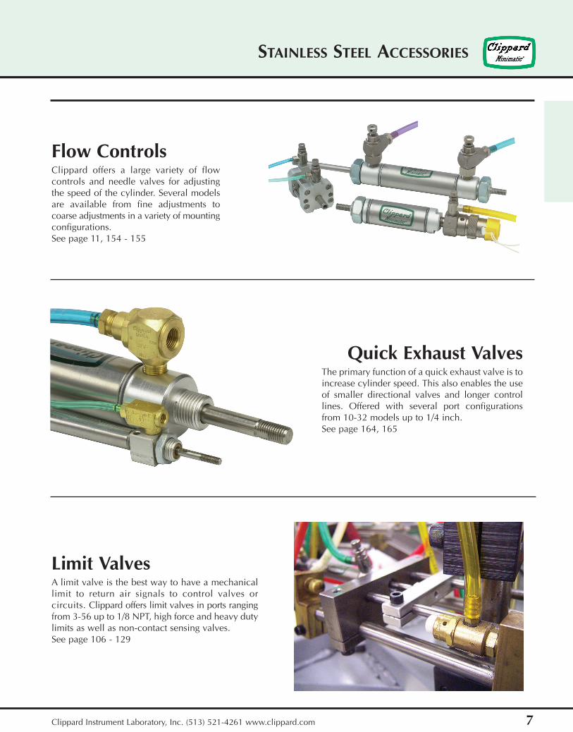
Limit ValvesA limit valve is the best way to have a mechanicallimit to return air signals to control valves orcircuits. Clippard offers limit valves in ports rangingfrom 3-56 up to 1/8 NPT, high force and heavy dutylimits as well as non-contact sensing valves.See page 106 - 129
Quick Exhaust ValvesThe primary function of a quick exhaust valve is toincrease cylinder speed. This also enables the useof smaller directional valves and longer controllines. Offered with several port configurationsfrom 10-32 models up to 1/4 inch.See page 164, 165
Flow ControlsClippard offers a large variety of flowcontrols and needle valves for adjustingthe speed of the cylinder. Several modelsare available from fine adjustments tocoarse adjustments in a variety of mountingconfigurations.See page 11, 154 - 155

5/16” BORE STAINLESS STEEL CYLINDER
8 Clippard Instrument Laboratory, Inc. (513) 521-4261 www.clippard.com
For bumpers add .250
Standard Stroke Lengths: 1/2, 1, 1-1/2, 2, 3, 4Spring Compressed: 1 lbs. Spring At Rest: 0.5 lbs.
Mount: StudType: Rotating Rod
Options: B, H, V, S, NSSR-05-❑-❑
.375
.343
1.125* + .750 foreach 1/2" of stroke
.312
5-40 thd. 1/4-28 thd.
.343dia.
10-32 thd. port
USR-05-❑-❑
SDR-05-❑-❑
.375
.343
.3121.562 + stroke
.468.312
5-40 thd.
.375
3/8-24 thd.
10-32 thd.
2 mounting holes .116 dia. thru
.343dia.
.500
.500
10-32 thd. port.156
UDR-05-❑-❑2.187 + stroke
.375
.343
.312
.468.312
5-40 thd.
3/8-24 thd.10-32 thd.
.156
2 mounting holes.116 dia. thru
.375
.375.187
.437dia.
10-32 thd. port3/8-24 thd.
.125 dia.
.500
.500
.187 flats
*For bumpers add .250
For bumpers add .250
For bumpers add .250
Standard Stroke Lengths: 1/2, 1, 1-1/2, 2, 3, 4Spring Compressed: 1 lbs. Spring At Rest: 0.5 lbs.
Mount: UniversalType: Rotating Rod
Options: B, H, V, N
Standard Stroke Lengths: 1/2, 1, 1-1/2, 2, 3, 4Mount: StudType: Rotating Rod
Options: B, V, P6, P7, P8, S, N
Standard Stroke Lengths: 1/2, 1, 1-1/2, 2, 3, 4Mount: UniversalType: Rotating Rod
Options: B, V, P2, P3, P4, P5, P6, P7, P8, N
Single Acting
Single Acting
Double Acting
Double Acting
For S option add .220
1.750 + .750 foreach 1/2" of stroke
.375
.343.312
5-40 thd.1/4-28 thd.
.375
.187
.437dia.
.125 dia.3/8-24 thd.
10-32 thd. port.187 flats
For S option add .220

9
5/16” BORE STAINLESS STEEL CYLINDER
Clippard Instrument Laboratory, Inc. (513) 521-4261 www.clippard.com
Reverse Acting
Reverse Acting
For bumpers add .250
For bumpers add .250SRR-05-❑-❑
URR-05-❑-❑
Standard Stroke Lengths: 1/2, 1, 1-1/2, 2, 3, 4Spring Compressed: 1 lbs. Spring At Rest: 0.5 lbs.
Mount: StudType: Rotating Rod
Options: B, H, V, N
Standard Stroke Lengths: 1/2, 1, 1-1/2, 2, 3, 4Spring Compressed: 1 lbs. Spring At Rest: 0.5 lbs.
Mount: UniversalType: Rotating Rod
Options: B, H, V, P2, P3, P4, P5, P6, P7, P8, N
The “force factor” is thenominal area of the cylinderbore size. The chart to theright provides theoreticalforces in both the extendand retract stroke of allavailable bore sizes.
These values are theoreticaland make no allowance forfriction which varies withthe bore size. It is recom-mended that a 25% safetyfactor be allowed whenselecting a cylinder bore fornormal load movement. Inhigh speed applications thatnumber should be at least40%.
The extend and retract values differ due to the rod diameter.
.343
.375 + stroke
5-40 thd.3/8-24 thd.
10-32 thd.
.312
.468.312
.375
2 mounting holes.116 dia. thru.156
2.093 + .750for each .500 of stroke
.375
.187.500
.437dia. .500
10-32 thd.3/8-24 thd.
.125 dia.
.343
.375+ stroke
5-40 thd.
.312
.468
3/8-24 thd.
10-32 thd.
.156.375
.312
1.468 + .750for each .500 of stroke
.343dia.
10-32 thd.
.500
.500
2 mounting holes .116 dia. thru
F
P A
FORCE FACTORBore Size5/16 1/2 5/8 3/4 7/8 1-1/16 1-1/4 1-1/2 1-3/4 2 2-1/2 3
Force Factor - Extend (area).07 .19 .31 .44 .60 .88 1.2 1.7 2.4 3.1 4.9 7.0
Rod Size1/8 3/16 3/16 1/4 1/4 5/16 3/8 7/16 1/2 192 5/8 3/4
Rod Area.01 .03 .03 .05 .05 .08 .11 .15 .20 .20 .31 .44
Force Factor - Retract (area).06 .16 .28 .39 .55 .80 1.09 1.55 2.2 2.9 4.59 6.56
20 PSI - Extend (lbs)1.4 3.8 6.2 8.8 12. 17.6 24. 34. 48. 62. 98. 140.
20 PSI - Retract (lbs)1.16 3.25 5.65 7.82 11.02 16.07 21.79 31. 44.07 58.07 91.86 131.16
50 PSI - Extend (lbs)3.5 9.5 15.5 22. 30. 44. 60. 85. 120. 155. 245. 350.
50 PSI - Retract (lbs)2.9 8.13 14.13 19.55 27.55 40.17 54.48 77.5 110.18 145.18 229.66 327.91
80 PSI - Extend (lbs)5.6 15.2 24.8 35.2 48. 70.4 96. 136. 192. 248. 392. 560.
80 PSI - Retract (lbs)4.64 13. 22.6 31.27 44.07 64.26 87.17 124. 176.29 232.29 367.46 524.66

5/16” BORE ACCESSORIES
10 Clippard Instrument Laboratory, Inc. (513) 521-4261 www.clippard.com
Stud Nut
Part Across Nut NutNumber Flats Thickness (Thread)
N04-28A 7/16 5/32 1/4-28
N04-28B 3/8 1/8 1/4-28
N06-24A 9/16 7/32 3/8-24
N06-24B 1/2 1/8 3/8-24
Rod Nut
Part Across Nut NutNumber Flats Thickness (Thread)
N02-40 1/4 3/32 5-40
.125 dia.
.390
.265
.250 sq..125
.562
.125
.375
#5-40 thd. .093
.125 dia.-thruboth sides
(2) retaining rings
RC-0581 Rod ClevisMaterial: steel, bright zinc plated
.875
1.187
.140
.156 dia.(2) places
.125 dia.(2) places
.187 .500
.156
.437
.187
.578
.312
CB-0595 Clevis BracketMaterial: steel, bright zinc plated
Foot BracketMaterial: steel, bright zinc platedFB-0591
1/4
.375
.375
.750.156 dia. mounting holes
.250 dia. .250 rad.
.437
1
.062
.375
.250
.156 dia. mounting holes.750
.375
.375 dia. .250 rad.
.062.437
1
FB-0592 Foot BracketMaterial: steel, bright zinc plated
MOUNTING NUTS

11
CYLINDER FLOW CONTROLS
Clippard Instrument Laboratory, Inc. (513) 521-4261 www.clippard.com
Flow Controls
Clippard provides a full range of stainless steel cylinders andMinimatic® cylinders. To compliment this offering, we alsomanufacture a variety of flow controls to meet the variedneeds of our customers. Large and small alike, cylindersoften need speed controls, and Clippard flow controlsprovide that needed control. From the MFC series(#10-32 ports) to JFC series (1/8” NPT ports) flowcontrols are designed for ease of use either directlyinstalled in the cylinder ports, or remotely (in-line orsubplate) mounted.
Clippard also offers a BFC (Block Flow Control) series of flow control valves.This product combines the features of our standard MFC series valve with a manifold-mount configuration to enable theuse of up to 8 flow controls in one body.
Whether you are remotely controlling the speed of up to eight miniature cylinders, or just like the convenience of all thespeed controls in one place, this series flow control is the right product for the application!
8
6
10
4
2
00 1 2 3 4 5 6 7 8
NUMBER OF TURNS
SC
FM
@ 1
00 P
SIG
MFC
-2
JFC
-2
MFC-3/BFCJF
C-3
9 10
MFC-2
MFC-3/BFC
JFC-2
JFC-3
Flow Controls Flow vs. Needle Turns

.750
.375
.750sq.
(2) mounting holes#8-32 thd. x .312 deep
.437dia.
.625
.062
.562
#10-32 thd.
.250.812
.437
(2) mounting holes#8-32 thd. x .187 deep
.437
1.875 + .937 foreach 1/2" of stroke
.156
.562dia.
#10-32 thd.
.375
1/2” BORE STAINLESS STEEL CYLINDER
12 Clippard Instrument Laboratory, Inc. (513) 521-4261 www.clippard.com
Standard Stroke Lengths: 1/2, 1, 1-1/2, 2, 3, 4Spring Compressed: 2 lbs. Spring At Rest: 0.9 lbs.
Mount: FrontType: Rotating Rod
Options: MB, B, H, V, S, N FSR-08-❑-❑
SSN-08-❑-❑
.625
.562 .312
10-32 thd.3/8-24 thd.
1.312 + .937 foreach 1/2" of stroke
.156
10-32 thd. port
SSR-08-❑-❑
.625
.562 .312
3/8-24 thd.10-32 thd.
.156
1.312 + .937 foreach 1/2" of stroke
10-32 thd. port
USN-08-❑-❑
.312 flats
.687 dia.
7/16-20 thd.
.156 dia.
.250.500
10-32 thd.3/8-24 thd..187 hex.
#10-32 thd.
2 + .937 for each 1/2" of stroke
.312.625
.562
Standard Stroke Lengths: 1/2, 1, 1-1/2, 2, 3, 4Spring Compressed: 2 lbs. Spring At Rest: 0.9 lbs.
Mount: StudType: Non-Rotating Rod
Options: MB, B, H, V, S, N
Standard Stroke Lengths: 1/2, 1, 1-1/2, 2, 3, 4Spring Compressed: 2 lbs. Spring At Rest: 0.9 lbs.
Mount: StudType: Rotating Rod
Options: MB, B, H, V, S, N
Standard Stroke Lengths: 1/2, 1, 1-1/2, 2, 3, 4Spring Compressed: 2 lbs. Spring At Rest: 0.9 lbs.
Mount: UniversalType: Non-Rotating Rod
Options: MB, B, H, V, P6, N
Single Acting
Single Acting
Single Acting
Single Acting
For bumpers add .500” For magnetic bumpers add .812
For bumpers add .500” For magnetic bumpers add .812
Bumpers add .500For magnetic bumpers add .812
Furnished without nut(s)See chart on page 15
For S option add .187
For bumpers add .500” For magnetic bumpers add .812
For S option add .187
For S option add .187

13
1/2” BORE STAINLESS STEEL CYLINDER
Clippard Instrument Laboratory, Inc. (513) 521-4261 www.clippard.com
USR-08-❑-❑
.312 flats
.687 dia.
7/16-20 thd..156 dia.
.250
.500
10-32 thd.
2 + .937 for each 1/2" of stroke
3/8-24 thd.
.312
#10-32 thd.
.562
.625
FDR-08-❑-❑
.750
.375
(2) mounting holes#8-32 thd. x .312 deep
.750sq.
.437dia.
.562
#10-32 thd.
.625
.062
.250.437
.687.812
(2) mounting holes #8-32 thd. x .187 deep opposite side
.437
2.062 + stroke
.156
.562dia.
#10-32 thd.both ports
.375
SDR-08-❑-❑
.625
.562
.375
#10-32 thd.
7/16-20 thd.10-32 thd.
2.125 + stroke
.156
.562dia.
10-32 thd. port
.375 flats
UDR-08-❑-❑
.312 flats
.687 dia.
.156 dia.10-32 thd.
.250
.500
2.812 + stroke
7/16-20 thd. typ.#10-32 thd.
.562
.625 .375
Standard Stroke Lengths: 1/2, 1, 1-1/2, 2, 3, 4Spring Compressed: 2 lbs. Spring At Rest: 0.9 lbs.
Mount: UniversalType: Rotating Rod
Options: MB, B, H, V, P6, N
Standard Stroke Lengths: 1/2, 1, 1-1/2, 2, 3, 4Mount: FrontType: Rotating Rod
Options: MB, B, V, P6, P7, P8, S, N
Standard Stroke Lengths: 1/2, 1, 1-1/2, 2, 3, 4Mount: StudType: Rotating Rod
Options: MB, B, V, P6, P7, P8, S, N
Standard Stroke Lengths: 1/2, 1, 1-1/2, 2, 3, 4Mount: UniversalType: Rotating Rod
Options: MB, B, V, P2, P3, P4, P5, P6, P7, P8, NDouble Acting
Double Acting
Double Acting
Single Acting
Bumpers add .500 For magnetic bumpers add .812
Furnished without nut(s)See chart on page 15
Bumpers add .500For magnetic bumpers add .812
Bumpers add .500For magnetic bumpers add .812
Furnished without nut(s)See chart on page 15
Bumpers add .500 For magnetic bumpers add .812
For S option add .187
For S option add .187
1/2” BORE STAINLESS STEEL CYLINDER
14 Clippard Instrument Laboratory, Inc. (513) 521-4261 www.clippard.com
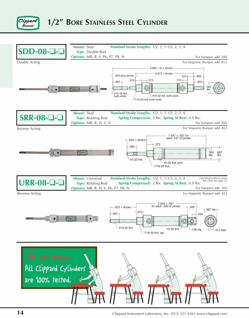
Standard Stroke Lengths: 1/2, 1, 1-1/2, 2, 3, 4Mount: StudType: Double Rod
Options: MB, B, V, P6, P7, P8, NSDD-08-❑-❑
.562
#10-32 thd.both ends
.625 plus stroke
4.062 + (2 x stroke)
.375 .312
2.812 + stroke
7/16-20 thd. both ends#10-32 thd. both ports
.312.375 .625
.562
.687dia.
SRR-08-❑-❑
.625 + stroke
.562
10-32 thd.
.375
1.937 + .937 foreach 1/2" of stroke
7/16-20 thd.10-32 thd. port
.562dia.
.687dia.
URR-08-❑-❑
.312 flats
.687 dia.
.156 dia.10-32 thd.
.250
.5002.625 + .937
for each .500 of stroke
7/16-20 thd. typ.
.375
.625 + stroke
.562
#10-32 thd.
For bumpers add .500
For bumpers add .500
Standard Stroke Lengths: 1/2, 1, 1-1/2, 2, 3, 4Spring Compressed: 2 lbs. Spring At Rest: 0.9 lbs.
Mount: StudType: Rotating Rod
Options: MB, B, H, V, N
Standard Stroke Lengths: 1/2, 1, 1-1/2, 2, 3, 4Spring Compressed: 2 lbs. Spring At Rest: 0.9 lbs.
Mount: UniversalType: Rotating Rod
Options: MB, B, H, V, P6, P7, P8, N
Double Acting
Reverse Acting
Reverse Acting
For bumpers add .500
For Magnetic Bumper add .812
For Magnetic Bumper add .812
For Magnetic Bumper add .812
Furnished without nut(s)See chart on page 15

Stud Nut
Part Across Nut NutNumber Flats Thickness (Thread)
N06-24A 9/16 7/32 3/8-24
N06-24B 1/2 1/8 3/8-24
N07-20 11/16 1/4 7/16-20
Rod Nut
Part Across Nut NutNumber Flats Thickness (Thread)
N03-32 3/8 1/8 10-32
.187 dia.-thruboth sides
.625
.312 dia. .187 dia..562
.375 sq..187
.187
.937
#10-32 thd..125
15
1/2” BORE ACCESSORIES
Clippard Instrument Laboratory, Inc. (513) 521-4261 www.clippard.com
RC-0881 Rod ClevisMaterial: steel, bright zinc plated
.203
.218 .875
.312 .500
.218
.500
.125
.203
.156 dia.
.750
.765.562
CB-0895 Clevis BracketMaterial: steel, bright zinc plated
Foot BracketMaterial: steel, bright zinc platedFB-0891
.500
.312
.625
1
.203
.375 dia.
.312 rad.
.562
1.375
.062
.500
.312
.625
.203
1
.437 dia.
.312 rad. .062
.562
1.375
.625 dia.
1.062
.406 dia.
Lockwasher
Locknut
#10-32.312 Body Flats
Bronze Bearing
.1900 dia.
.312
Hardened SteelChrome PlatedInner AlignmentBall
Body
13
RE-0885 Rod EndMaterial: steel, bright zinc plated body
FB-0892 Foot BracketMaterial: steel, bright zinc plated
MOUNTING NUTS
Max. Static Radial Load: 1624 lbs.
Fits RodThread Size: #10-32

5/8” BORE STAINLESS STEEL CYLINDER
16 Clippard Instrument Laboratory, Inc. (513) 521-4261 www.clippard.com
Standard Stroke Lengths: 1/2, 1, 1-1/2, 2, 3, 4Spring Compressed: 4 lbs. Spring At Rest: 1.3 lbs.
Mount: UniversalType: Non-Rotating Rod
Options: MB, B, H, V, P6, NUSN-10-❑-❑
.625
.562
#10-32 thd.
.187 hex. s.s. rod (non-rotating)
3/8-24 thd.
.312
2 + 1.875 foreach 1" of stroke
#10-32 thd.
.187.500
.250
.156 dia.
.687dia.
.312
7/16-20 thd.
USR-10-❑-❑
.625
.562.312
2 + .937 foreach 1/2" of stroke
#10-32 thd.
3/8-24 thd.
#10-32 thd.
.156 dia.
.187.500
.250
.687dia.
.312
.156 dia.
SSN-10-❑-❑
.625
.562.312
#10-32 thd.
1.312 + .937 foreach 1/2" of stroke
3/16 hex. s.s. rod (non-rotating)3/8-24 thd.
.156
.687dia.
#10-32 thd.
.500
SSR-10-❑-❑
.562
.625
#10-32 thd. 3/8-24 thd.
.312
1.312 + .937 foreach 1/2" of stroke
.156
.687dia.
#10-32 thd.
.500
Standard Stroke Lengths: 1/2, 1, 1-1/2, 2, 3, 4Spring Compressed: 4 lbs. Spring At Rest: 1.3 lbs.
Mount: UniversalType: Rotating Rod
Options: MB, B, H, V, P6, N
Standard Stroke Lengths: 1/2, 1, 1-1/2, 2, 3, 4Spring Compressed: 4 lbs. Spring At Rest: 1.3 lbs.
Mount: StudType: Non-Rotating Rod
Options: MB, B, H, V, S, N
Standard Stroke Lengths: 1/2, 1, 1-1/2, 2, 3, 4Spring Compressed: 4 lbs. Spring At Rest: 1.3 lbs.
Mount: StudType: Rotating rod
Options: MB, B, H, V, S, N
Single Acting
Single Acting
Single Acting
JSingle Acting
Furnished without nut(s)See chart on page 19
For bumpers add .500 For magnetic bumpers add .812
For bumpers add .500 For magnetic bumpers add .812
Bumpers add .500 For magnetic bumpers add .812
Bumpers add .500 For magnetic bumpers add .812
Furnished without nut(s)See chart on page 19

17
5/8” BORE STAINLESS STEEL CYLINDER
Clippard Instrument Laboratory, Inc. (513) 521-4261 www.clippard.com
FSR-10-❑-❑
.750
.375
.750sq.
(2) mounting holes#8-32 thd. x .312 deep
.437dia.
.562
.625
.062
10-32 thd.
(2) mounting holes#8-32 thd. x .187 deep
.250
.812
.437
.437
1.875 + .937 foreach 1/2" of stroke
.156
.687dia.
#10-32 thd.
.500
FDR-10-❑-❑
.750
.375
(2) mounting holes#8-32 thd. x .312 deep
.750sq.
.437dia.
#10-32 thd.
.562
.625
.062
.250 .437
.687
.812
7/16
2.062 + stroke
.156
.687dia.
#10-32 thd. both ports
.500
(2) mounting holes #8-32 thd..187 deep opposite side
SDR-10-❑-❑
.625
.562
.375
#10-32 thd.
7/16-20 thd.
#10-32 thd. both ports
2.125 + stroke
.156
.687dia. .500
.312
UDR-10-❑-❑
.625
.562
.375
.312
2.812 + stroke
.187
.500.250
.687dia.
.312
.156 dia.#10-32 thd.
7/16-20 thd. both ends
#10-32 thd. both ports
Standard Stroke Lengths: 1/2, 1, 1-1/2, 2, 3, 4Spring Compressed: 4 lbs. Spring At Rest: 1.3 lbs.
Mount: FrontType: Rotating Rod
Options: MB, B, H, V, S, N
Standard Stroke Lengths: 1/2, 1, 1-1/2, 2, 3, 4Mount: FrontType: Rotating Rod
Options: MB, B, V, P6, P7, P8, S, N
Standard Stroke Lengths: 1/2, 1, 1-1/2, 2, 3, 4Mount: StudType: Rotating Rod
Options: MB, B, V, P6, P7, P8, S, N
Standard Stroke Lengths: 1/2, 1, 1-1/2, 2, 3, 4Mount: UniversalType: Rotating Rod
Options: MB, B, V, P2, P3, P4, P5, P6, P7, P8, NDouble Acting
Double Acting
Double Acting
Single Acting
Furnished without nut(s)See chart on page 19
For bumpers add .500For magnetic bumpers add .812
For bumpers add .500For magnetic bumpers add .812
For bumpers add .500For magnetic bumpers add .812
Furnished without nut(s)See chart on page 19
For bumpers add .500 For magnetic bumpers add .812
For S option add .187
For S option add .187
For S option add .187

5/8” BORE STAINLESS STEEL CYLINDER
18 Clippard Instrument Laboratory, Inc. (513) 521-4261 www.clippard.com
Standard Stroke Lengths: 1/2, 1, 1-1/2, 2, 3, 4Mount: StudType: Double Rod
Options: MB, B, V, P6, P7, P8, NSDD-10-❑-❑
.625 + stroke
.562
#10-32 thd.both ends
7/16-20 thd. both ends#10-32 thd. both ports
.375.312
4.062 + (2 x stroke)
2.812 + stroke
.312.375
.562
.625
.687dia.
SRR-10-❑-❑
.625 + stroke
.562
#10-32 thd.
.375.312
7/16-20 thd. #10-32 thd.
1.937 + .937 foreach 1/2" of stroke
.687dia.
URR-10-❑-❑
.625 + stroke
9/16
.375.312
#10-32 thd. both ends
7/16-20 thd. both ends
#10-32 thd.
2.625 + .937 foreach 1" of stroke
.500.250
.156 dia.
.687dia.
.312
For bumpers add .500
Standard Stroke Lengths: 1/2, 1, 1-1/2, 2, 3, 4Spring Compressed: 4 lbs. Spring At Rest: 1.3 lbs.
Mount: StudType: Rotating Rod
Options: MB, B, H, V, N
Standard Stroke Lengths: 1/2, 1, 1-1/2, 2, 3, 4Spring Compressed: 4 lbs. Spring At Rest: 1.3 lbs.
Mount: UniversalType: Rotating Rod
Options: MB, B, H, V, P6, N
Double Acting
Reverse Acting
Reverse Acting
For bumpers add .500For magnetic bumpers add .812
Furnished without nut(s)See chart on page 19

19
5/8” BORE ACCESSORIES
Clippard Instrument Laboratory, Inc. (513) 521-4261 www.clippard.com
Stud Nut
Part Across Nut NutNumber Flats Thickness (Thread)
N06-24A 9/16 7/32 3/8-24
N06-24B 1/2 1/8 3/8-24
N07-20 11/16 1/4 7/16-20
Rod Nut
Part Across Nut NutNumber Flats Thickness (Thread)
N03-32 3/8 1/8 10-32
.187 dia.-thruboth sides
.625
.312 dia. .187 dia..562
.375 sq..187
.187
.937
#10-32 thd..125
RC-0881 Rod ClevisMaterial: steel, bright zinc plated
.203
.218 .875
.312 .500
.218
.500
.125
.203
.156 dia.
.750
.765.562
CB-0895 Clevis BracketMaterial: steel, bright zinc plated
Foot BracketMaterial: steel, bright zinc platedFB-0891
.500
.312
.625
1
.203
.375 dia.
.312 rad.
.562
1.375
.062
.500
.312
.625
.203
1
.437 dia.
.312 rad. .062
.562
1.375
.625 dia.
1.062
.406 dia.
Lockwasher
Locknut
#10-32.312 Body Flats
Bronze Bearing
.1900 dia.
.312
Hardened SteelChrome PlatedInner AlignmentBall
Body
13
RE-0885 Rod EndMaterial: steel, bright zinc plated body
FB-0892 Foot BracketMaterial: steel, bright zinc plated
MOUNTING NUTS
Max. Static Radial Load: 1624 lbs.
Fits RodThread Size: #10-32

3/4” BORE STAINLESS STEEL CYLINDER
20 Clippard Instrument Laboratory, Inc. (513) 521-4261 www.clippard.com
Standard Stroke Lengths: 1/2, 1, 1-1/2, 2, 3, 4Spring Compressed: 6 lbs. Spring At Rest: 3 lbs.
Mount: FrontType: Rotating Rod
Options: MB, B, H, V, S, NFSR-12-❑-❑
1.000
.500
(2) mounting holes#10-32 thd. x .312 deep
.625dia.
1/4-28 thd.
.562.625
(2)mounting holes .343 dia. x .218 deep counter bore .205 dia. - thru 1/4-20 thd. x .250 deep from far side
.093
.375
2.218 + 1.687 foreach 1" of stroke
.156
.625.812dia. 1 sq.
1/8-27 NPT
SSN-12-❑-❑
.625
.562.437
1/4-28 thd.1/4 hex. s.s. rod (non-rotating)
1/2-20 thd.
1.500 + 1.687 foreach 1" of stroke
.156
.625 .812dia.
1/8-27 NPT
SSR-12-❑-❑
.625
.562
1/4-28 thd.1/2-20 thd.
.437
1.500 + 1.687 foreach 1" of stroke
.156
.625.812dia.
1/8-27 NPT
TSR-12-❑-❑
.625dia.
1/4-28 thd.
.562.625
.093
.343
2.218 + 1.687 foreach 1" of stroke
.156
.625.812dia.
1.750
1 sq.
1/8-27 NPT.500 dia.
Standard Stroke Lengths: 1/2, 1, 1-1/2, 2, 3, 4Spring Compressed: 6 lbs. Spring At Rest: 3 lbs.
Mount: StudType: Non-Rotating Rod
Options: MB, B, H, V, S, N
Standard Stroke Lengths: 1/2, 1, 1-1/2, 2, 3, 4Spring Compressed: 6 lbs. Spring At Rest: 3 lbs.
Mount: StudType: Rotating Rod
Options: MB, B, H, V, S, N
Standard Stroke Lengths: 1/2, 1, 1-1/2, 2, 3, 4Spring Compressed: 6 lbs. Spring At Rest: 3 lbs.
Mount: TrunnionType: Rotating Rod
Options: MB, B, H, V, S, N
Single Acting
Single Acting
Single Acting
Single Acting
For bumpers add .500 For magnetic bumpers add .812
For bumpers add .500 For magnetic bumpers add .812
For bumpers add .500 For magnetic bumpers add .812
For bumpers add .500 For magnetic bumpers add .812
For S option add .437
For S option add .437
For S option add .437
For S option add .437

21
3/4” BORE STAINLESS STEEL CYLINDER
Clippard Instrument Laboratory, Inc. (513) 521-4261 www.clippard.com
USN-12-❑-❑
.562
.625.437
1/4-28 thd..250 hex. s.s. rod (non-rotating)
1/2-20 thd.
2.562 + 1.687 foreach 1" of stroke
.312.625
.281 .375
.875dia.
.250 dia.5/8-18 thd.
USR-12-❑-❑
.625
.562.437
1/4-28 thd.1/2-20 thd.
2.562 + 1.687 for each 1" of stroke
.312.625
.281
.250 dia.5/8-18 thd.
.875dia.
.375
FDR-12-❑-❑
1
.500
(2) mounting holes#10-32 thd. x 5/16 deep
.625dia.
.562.625
.093
.375
.875
1/4-28 thd.
(2) mounting holes .343 dia. x .218 deep counterbore .205 dia. - thru 1/4-20 thd. x .250 deep from far side
1/8-27 NPT both ports
2.875 + stroke
.156
.625.812dia. 1 sq.
TDR-12-❑-❑
.625
.562
.625dia.
.093
.343
.875
2.875 + stroke
.156
.625.812dia.
1.750
1 sq.
1/4-28 thd.
.500 dia.
1/8-27 NPT both ports
Standard Stroke Lengths: 1/2, 1, 1-1/2, 2, 3, 4Spring Compressed: 6 lbs. Spring At Rest: 3 lbs.
Mount: UniversalType: Non-Rotating Rod
Options: MB, B, H, V, P6, N
Standard Stroke Lengths: 1/2, 1, 1-1/2, 2, 3, 4Spring Compressed: 6 lbs. Spring At Rest: 3 lbs.
Mount: UniversalType: Rotating Rod
Options: MB, B, H, V, P6, N
Standard Stroke Lengths: 1/2, 1, 1-1/2, 2, 3, 4, 5, 6Mount: FrontType: Rotating Rod
Options: MB, B, W, V, P6, P7, P8, S, N
Standard Stroke Lengths: 1/2, 1, 1-1/2, 2, 3, 4, 5, 6Mount: TrunnionType: Rotating Rod
Options: MB, B, W, V, S, NDouble Acting
Double Acting
Single Acting
Single Acting
Furnished without nut(s)See chart on page 25
Furnished without nut(s)See chart on page 25
For bumpers add .500For magnetic bumpers add .812
For bumpers add .500For magnetic bumpers add .812
For bumpers add .500 For magnetic bumpers add .812
For bumpers add .500 For magnetic bumpers add .812
For S option add .437
For S option add .437

3/4” BORE STAINLESS STEEL CYLINDER
22 Clippard Instrument Laboratory, Inc. (513) 521-4261 www.clippard.com
Standard Stroke Lengths: 1/2, 1, 1-1/2, 2, 3, 45, 6, 8, 10, 12
Mount: StudType: Rotating rod
Options: C, F, R, MB, B, W, V, P2, P3, P4, P5, P6, P7, P8, M, NUDR-12-❑-❑
.625
.562
.500
.468
1/4-28 thd.
5/8-18 thd. both ends
1/8-27 NPT both ports
4.031 + stroke
.312
.625
.281
.250 dia.
.875dia.
.375
SDR-12-❑-❑
.625
.562
1/4-28 thd.5/8-18 thd.
1/8-27 NPT both ports
.500.468
2.968 + stroke
.156
.652 .875dia.
SDD-12-❑-❑
.625 + stroke
.562.500 .468
1/4-28 thd. both ends5/8-18 thd. both ends
1/8-27 NPT both ports
4" + stroke5.250+ (2 x stroke)
.468.500
.625
.562.875dia.
SDH-12-❑-❑
.062 dia. - thru
1/4-28 thd. both ends
.562
.625 + stroke .500.468
5/8-18 thd. both ends
1/8-27 NPT both ports
5.250 + (2*stroke)
4" + stroke
.468.500 .625
.562
.875dia.
Standard Stroke Lengths: 1/2, 1, 1-1/2, 2, 3, 4, 5, 6Mount: StudType: Rotating Rod
Options: C, F, R, MB, B, W, V, P6, P7, P8, S, M, N
Standard Stroke Lengths: 1, 2, 3, 4, 5, 6Mount: StudType: Double Rod
Options: C, F, MB, B, W, V, P6, P7, P8, M, N
Standard Stroke Lengths: 1, 2, 3, 4, 5, 6Mount: StudType: Hollow Rod
Options: C, F, MB, B, W, V, P6, P7, P8, M, N
Double Acting
Double Acting
Double Acting
Double Acting
For bumpers add .500For magnetic bumpers add .812
Furnished without nut(s)See chart on page 25
For bumpers add .500For magnetic bumpers add .812
Bumpers add .500 For magnetic bumpers add .812
For bumpers add .500For magnetic bumpers add .812
For magnet add .312
For C, F, R & S options add .437For magnet add .312
For CM, FM add .312
For CM, FM add .312
For C, F, & R options use side ported rear head

23
3/4” BORE STAINLESS STEEL CYLINDER
Clippard Instrument Laboratory, Inc. (513) 521-4261 www.clippard.com
For bumpers add .375
For bumpers add .375
For bumpers add .375SRR-12-❑-❑
.625 + stroke.562
1/4-28 thd.both ends
5/8-18 thd.1/8-27 NPT
.500.468
2.312 + 1.687 foreach 1" of stroke
.875dia.
URR-12-❑-❑
.562
1/4-28 thd. both ends
.625 + stroke
.500 .468
5/8-18 thd.both ends
1/8-27 NPT .250 dia.
.281
.625
2.718 + 1.687 for each 1" of stroke
.875dia.
.375
SFD-12-❑-❑
.562
1/4-28 thd. both ends
.625 + stroke.500
.468
5/8-18 thd. both ends
1/8-27 NPT both ports
.468
.500
5.375 + 2.687for each 1" of stroke
4.125 + 1.687for each 1" of stroke .625
.562
.875dia.
SBR-12-❑-❑
.562
.625 + stroke
1/4-28 thd.
5/8-18 thd.1/8-27 NPT both ports
.500.468
3.093 + 1.687for each 1" of stroke
.156
.625 .875dia.
Standard Stroke Lengths: 1/2, 1, 1-1/2, 2, 3, 4Spring Compressed: 6 lbs. Spring At Rest: 3 lbs.
Mount: StudType: Rotating Rod
Options: MB, B, H, W, V, N
Standard Stroke Lengths: 1/2, 1, 1-1/2, 2, 3, 4Spring Compressed: 6 lbs. Spring At Rest: 3 lbs.
Mount: UniversalType: Rotating Rod
Options: MB, B, H, W, V, P6, N
Standard Stroke Lengths: 1/2, 1, 1-1/2, 2, 3, 4Spring Compressed: 6 lbs. Spring At Rest: 3 lbs.
Mount: StudType: Double Rod
Options: MB, B, H, W, V, P6, P7, P8, N
Standard Stroke Lengths: 1/2, 1, 1-1/2, 2, 3, 4Spring Compressed: 6 lbs. Spring At Rest: 3 lbs.
Mount: StudType: Rotating Rod
Options: MB, B, H, W, V, P6, P7, P8, S, NDouble Acting, Rear Spring Bias
Double Acting, Spring Bias
Reverse Acting
Reverse Acting
For bumpers add .500
Furnished without nut(s)See chart on page 25
For magnetic bumpers add .687
For magnetic bumpers add .812
For magnetic bumpers add .687
For magnetic bumpers add .687For S option add .437

3/4” BORE STAINLESS STEEL CYLINDER
24 Clippard Instrument Laboratory, Inc. (513) 521-4261 www.clippard.com
Standard Stroke Lengths: 1/2, 1, 1-1/2, 2, 3, 4Spring Compressed: 6 lbs. Spring At Rest: 3 lbs.
Mount: StudType: Rotating Rod
Options: MB, B, H, W, V, P6, P7, P8, S, NSFR-12-❑-❑
.562
.625.500
.406
1/4-28 thd.
5/8-18 thd. 1/8-27 NPT both ports
.625
.156
3.093 + 1.687for each 1" of stroke
.875dia.
UBR-12-❑-❑
.375
.875dia.
.250 dia.
.281
.625.312
4.156 + 1.687for each 1" of stroke
.500.468
.625 + stroke
.562
1/4-28 thd.
5/8-18 thd. both ends1/8-27 NPT both ports
UFR-12-❑-❑
.375
.875dia.
.281
.250 dia.
.625.312
4.156 + 1.687for each 1" of stroke
1/8-27 NPT both ports
.468
5/8-18 thd. both ends
.500.625
.562
1/4-28 thd.
For bumpers add .375
For bumpers add .375
For bumpers add .375
Standard Stroke Lengths: 1/2, 1, 1-1/2, 2, 3, 4Spring Compressed: 6 lbs. Spring At Rest: 3 lbs.
Mount: UniversalType: Rotating Rod
Options: MB, B, H, W, V, P2, P3, P4, P5, P6, P7, P8, N
Standard Stroke Lengths: 1/2, 1, 1-1/2, 2, 3, 4Spring Compressed: 6 lbs. Spring At Rest: 3 lbs.
Mount: UniversalType: Rotating Rod
Options: MB, B, H, W, V, P2, P3, P4, P5, P6, P7, P8, N
Double Acting, Front Spring Bias
Double Acting, Rear Spring Bias
Double Acting, Front Spring Bias
For magnetic bumpers add .687For S option add .437
For magnetic bumpers add .687
For magnetic bumpers add .687
Cad Files:Cad Files:Clippard offers all of our products in CAD format at our website,
www.clippard.com. Download the files and insert them into your designto save time and money. CD’s are available upon special request.
visit our site at wwwvisit our site at www.clippard.com.clippard.com

25
3/4” BORE ACCESSORIES
Clippard Instrument Laboratory, Inc. (513) 521-4261 www.clippard.com
Stud Nut
Part Across Nut NutNumber Flats Thickness (Thread)
N08-20 3/4 5/16 1/2-20
N10-18 15/16 3/8 5/8-18
Rod Nut
Part Across Nut NutNumber Flats Thickness (Thread)
N04-28A 7/16 5/32 1/4-28
N04-28B 3/8 1/8 1/4-28
.750
.375dia.
.250 dia.
.250 dia.-thruboth sides
.500 sq..250
.250
1/4-28 thd.
.687
1.187
.156
RC-1281 Rod ClevisMaterial: steel, bright zinc plated
.375 1.250 .375
.375
.812.265
.750
.187
.312
.250 dia.
1.125
1.156.875
CB-1795 Clevis BracketMaterial: steel, bright zinc plated
Foot BracketMaterial: steel, bright zinc platedFB-1291
.750
.437
.625
1.250
.203
.500 dia.
.406 rad.
.687
.125
1.625
.750
.265
1.500
.5621
.625 dia.
.562 rad.
.812
1.875
.125
.750 dia.
1.312
.468 dia
Lockwasher
Locknut
1/4-28.375 Body Flats
Bronze Bearing
.2500 dia.
.375
Hardened SteelChrome PlatedInner AlignmentBall
Body
16
RE-1285 Rod EndMaterial: steel, bright zinc plated body
FB-1791 Foot BracketMaterial: steel, bright zinc plated
MOUNTING NUTS
Max. Static Radial Load: 2545 lbs.
Fits RodThread Size: 1/4-28


![Untitled-1 [] · Cushion: M*2 Cushion: M*2 Cushion: M*1 Cushion: M*1 Cushion: M*2 Cushion: M*3 Cushion: M*4 Cushion: S*3 Cushion: S*2 Cushion: S*1 Cushion: M*3 S*2 Cushion: M*2 S*1](https://img.pdfslide.us/doc/110x75/5fcbbac82e8c411bf55b5c66/untitled-1-cushion-m2-cushion-m2-cushion-m1-cushion-m1-cushion-m2.jpg)