Embed Size (px)
Citation preview
Yingli Solar PANDA Bifacial Modules, Installation and User Manual page 1
This manual applies to photovoltaic PANDA Bifacial modules (“PANDA Bifacial modules”, also commonly known as Double Glass Modules) manufactured by Yingli Green Energy Holding Co. Ltd. (“Yingli Solar”), and is explicitly written for qualified professionals (“Installer” or “Installers”), including without limitation licensed electricians and RAL certified PV Installers.
I N T R O D U C T I O NThank you for choosing Yingli Solar as your PANDA Bifacial module provider. We appreciate your business! This manual contains important information pertaining to the electrical and mechanical installation and maintenance of PANDA Bifacial modules, and contains safety information that you must read carefully and be familiar with before handling, installing, and/or maintaining Yingli Solar PANDA Bifacial modules.
Yingli Solar does not assume responsibility and expressly disclaims liability for losses, damages, or expenses arising out of, or in any way connected with this Installation and User Manual. Yingli Solar assumes no responsibility for any infringement of patents or other rights of third parties, which may result from using Yingli Solar PANDA Bifacial modules. No license is granted expressly or by implication or under any patent or patent rights. The information in this manual is believed to be reliable, but does not constitute an expressed or implied warranty. Yingli Solar reserves the right to make changes to its PANDA Bifacial modules and other products, their specifications, or this manual without prior notice.
Yingli Solar and its subsidiaries are not liable for any damages caused by inappropriate installation, use, or maintenance of Yingli Solar PANDA Bifacial modules, including without limitation damages, losses, and expenses caused by non-observance of the instructions of this manual or caused by or in connection with products of other manufacturers.
Yingli Solar PANDA Bifacial modules are designed to meet the requirements for the standards IEC 61215 and IEC 61730, application class A. Modules rated for use in this application class may be used in systems operating at greater than 50 V DC or 240 W, where general contact access is anticipated. Modules qualified for safety through IEC 61730-1 and IEC 61730-2 and within this application class are considered to meet the requirements for safety class II. In the course of the PANDA Bifacial module certification process, the compliance of this manual with the certification requirements has been verified by an independent certification laboratory.
This Installation and User Manual is available in different languages. In cases of discrepancy between versions, the English language version shall control.
Failure to comply with the requirements listed in this manual will invalidate the Limited Warranty for PANDA Bifacial Modules as provided by Yingli Solar at the time of sale to the direct customer. Additional recommendations are provided to enhance safety practices and performance results. Please provide a copy of this manual to the PV system owner for their reference, and inform them of all relevant aspects of safety, operation, and maintenance.
S A F E T YGeneral You must understand and follow all applicable local, state, and federal regulations and standards for building construction, electrical design, fire, and safety, and must check with local authorities to determine applicable permitting requirements before attempting to install or maintain PANDA Bifacial modules. Rooftop PANDA Bifacial systems should only be installed on houses that have been formally analyzed for structural integrity, and confirmed to be capable of handling the additional load of PANDA Bifacial system components, including PANDA Bifacial modules, by a certified building specialist or engineer.
For your safety, do not attempt to work on a rooftop until safety precautions have been identified and taken, including without limitation fall protection measures, ladders or stairways, and personal protective equipment (PPE).
For your safety, do not install or handle PANDA Bifacial modules under adverse conditions, including without limitation strong or gusty winds, and wet or frosted roof surfaces.
PANDA Bifacial modules are photovoltaic products made of tempered glass, encapsulant, ribbon, cells, junction boxes. Figure 1 is an illustration of the PANDA Bifacial module components.
Figure 1: Module components and cross-section of the laminated assembly
ElectricalPANDA Bifacial modules can produce current and voltage when exposed to light of any intensity. Electrical current increases with higher light intensity. DC voltage of 30 Volts or higher is potentially lethal. Contacting the live circuitry of a PV system operating under light can result in lethal electric shock.
De-energize PANDA Bifacial modules by removing them entirely from light or by covering their front surface with an opaque material. Regard the safety regulations for live electrical equipment when working with modules that are exposed to any light. Use insulated tools and do not wear metallic jewelry while working with PANDA Bifacial modules.
In order to avoid arcing and electrical shock, do not disconnect electrical connections under load. Faulty connections can also result in arcing and electrical shock. Keep connectors dry and clean, and ensure that they are in proper working condition. Never insert metallic objects into the connectors, or
��
yinglisolar.com
YINGLI SOLAR PANDA Bifacial MODULES
Installation and User ManualRevision Date April 25th, 2017 | Applicable for IEC certified products
File name: Corporate Logo with Tagline / Vertical.ai
Yingli Solar PANDA Bifacial Modules, Installation and User Manual page 2
modify them in any way in order to secure an electrical connection.
Do not touch or handle PANDA Bifacial modules with broken glass, unless the modules are first disconnected and you are wearing proper Personal Protective Equipment. Avoid handling PANDA Bifacial modules when they are wet unless cleaning the PANDA Bifacial modules as directed in this manual. Never touch electrical connections that are wet without protecting yourself with insulated gloves.
Transport and HandlingYingli Solar PANDA Bifacial modules must be transported in the supplied packaging only and kept in the packaging until they are ready to be installed. At time of receipt, please verify that the delivered product is in fact the product ordered. The product name, subname, and serial number of each laminate are clearly marked on the outside of each packing box.
Leave the product in its original packing box until you are ready to install. Store pallets in a clean, cool, dry and flat place until the PANDA Bifacial modules are ready to be unpackaged with relative humidity below 85% and ambient temperatures between -20°C and 50°C. Protect pallets against movement and exposure to damage during transportation. DO NOT exceed the allowable maximum height of pallets to be stacked, as indicated on the pallet packaging. Secure pallets from falling over. If pallets are stored temporarily outside please place a protective covering over the pallet to protect it from direct weathering and do not stack pallets.
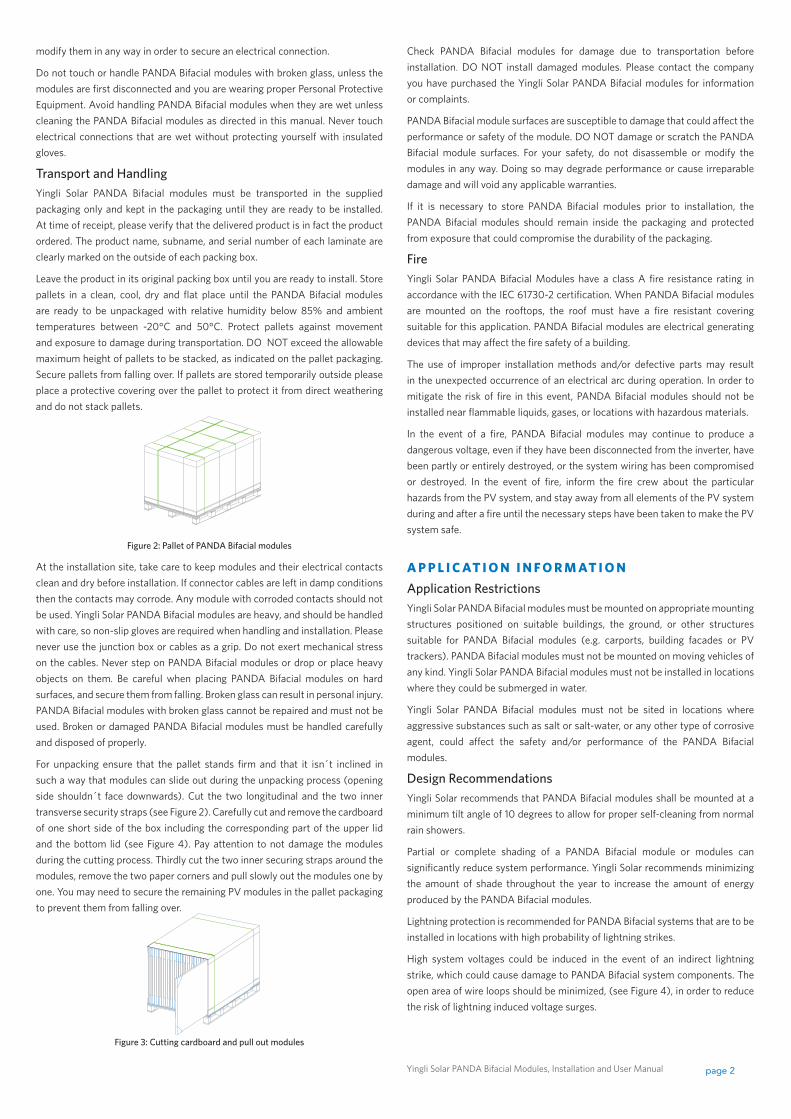
Figure 2: Pallet of PANDA Bifacial modules
At the installation site, take care to keep modules and their electrical contacts clean and dry before installation. If connector cables are left in damp conditions then the contacts may corrode. Any module with corroded contacts should not be used. Yingli Solar PANDA Bifacial modules are heavy, and should be handled with care, so non-slip gloves are required when handling and installation. Please never use the junction box or cables as a grip. Do not exert mechanical stress on the cables. Never step on PANDA Bifacial modules or drop or place heavy objects on them. Be careful when placing PANDA Bifacial modules on hard surfaces, and secure them from falling. Broken glass can result in personal injury. PANDA Bifacial modules with broken glass cannot be repaired and must not be used. Broken or damaged PANDA Bifacial modules must be handled carefully and disposed of properly.
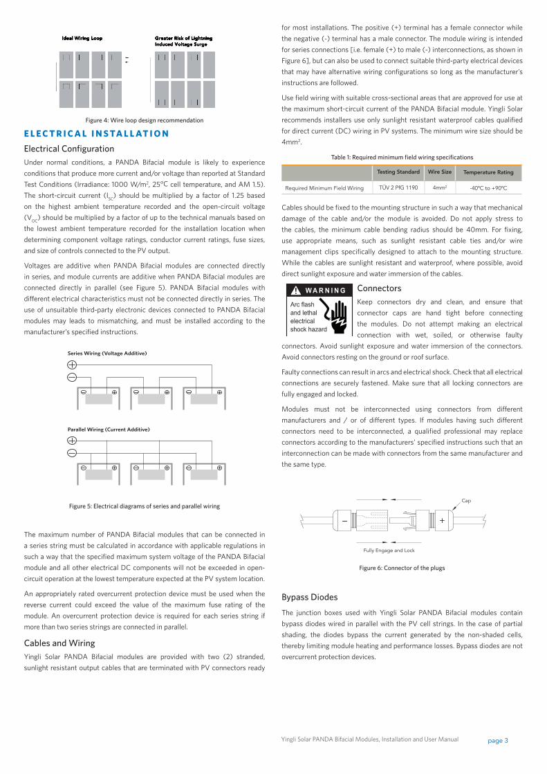
For unpacking ensure that the pallet stands firm and that it isn´t inclined in such a way that modules can slide out during the unpacking process (opening side shouldn´t face downwards). Cut the two longitudinal and the two inner transverse security straps (see Figure 2). Carefully cut and remove the cardboard of one short side of the box including the corresponding part of the upper lid and the bottom lid (see Figure 4). Pay attention to not damage the modules during the cutting process. Thirdly cut the two inner securing straps around the modules, remove the two paper corners and pull slowly out the modules one by one. You may need to secure the remaining PV modules in the pallet packaging to prevent them from falling over.
Figure 3: Cutting cardboard and pull out modules
Check PANDA Bifacial modules for damage due to transportation before installation. DO NOT install damaged modules. Please contact the company you have purchased the Yingli Solar PANDA Bifacial modules for information or complaints.
PANDA Bifacial module surfaces are susceptible to damage that could affect the performance or safety of the module. DO NOT damage or scratch the PANDA Bifacial module surfaces. For your safety, do not disassemble or modify the modules in any way. Doing so may degrade performance or cause irreparable damage and will void any applicable warranties.
If it is necessary to store PANDA Bifacial modules prior to installation, the PANDA Bifacial modules should remain inside the packaging and protected from exposure that could compromise the durability of the packaging.
FireYingli Solar PANDA Bifacial Modules have a class A fire resistance rating in accordance with the IEC 61730-2 certification. When PANDA Bifacial modules are mounted on the rooftops, the roof must have a fire resistant covering suitable for this application. PANDA Bifacial modules are electrical generating devices that may affect the fire safety of a building.
The use of improper installation methods and/or defective parts may result in the unexpected occurrence of an electrical arc during operation. In order to mitigate the risk of fire in this event, PANDA Bifacial modules should not be installed near flammable liquids, gases, or locations with hazardous materials.
In the event of a fire, PANDA Bifacial modules may continue to produce a dangerous voltage, even if they have been disconnected from the inverter, have been partly or entirely destroyed, or the system wiring has been compromised or destroyed. In the event of fire, inform the fire crew about the particular hazards from the PV system, and stay away from all elements of the PV system during and after a fire until the necessary steps have been taken to make the PV system safe.
A P P L I C AT I O N I N F O R M AT I O NApplication RestrictionsYingli Solar PANDA Bifacial modules must be mounted on appropriate mounting structures positioned on suitable buildings, the ground, or other structures suitable for PANDA Bifacial modules (e.g. carports, building facades or PV trackers). PANDA Bifacial modules must not be mounted on moving vehicles of any kind. Yingli Solar PANDA Bifacial modules must not be installed in locations where they could be submerged in water.
Yingli Solar PANDA Bifacial modules must not be sited in locations where aggressive substances such as salt or salt-water, or any other type of corrosive agent, could affect the safety and/or performance of the PANDA Bifacial modules.
Design RecommendationsYingli Solar recommends that PANDA Bifacial modules shall be mounted at a minimum tilt angle of 10 degrees to allow for proper self-cleaning from normal rain showers.
Partial or complete shading of a PANDA Bifacial module or modules can significantly reduce system performance. Yingli Solar recommends minimizing the amount of shade throughout the year to increase the amount of energy produced by the PANDA Bifacial modules.
Lightning protection is recommended for PANDA Bifacial systems that are to be installed in locations with high probability of lightning strikes.
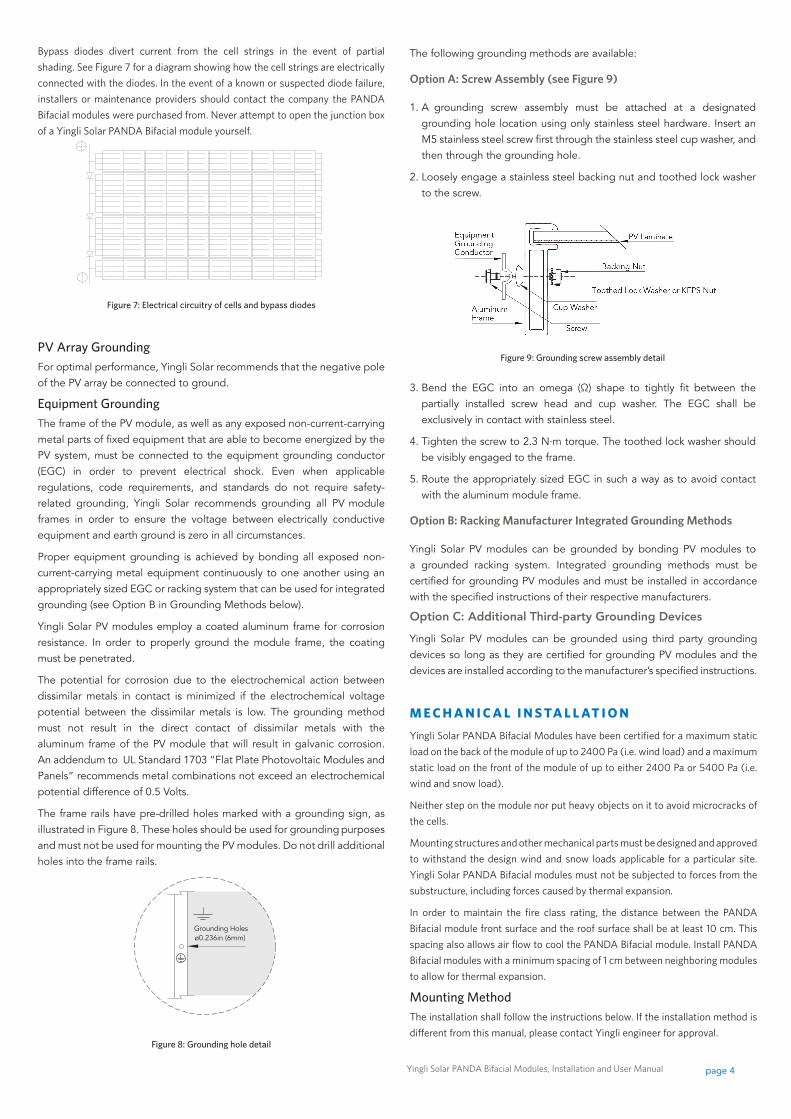
High system voltages could be induced in the event of an indirect lightning strike, which could cause damage to PANDA Bifacial system components. The open area of wire loops should be minimized, (see Figure 4), in order to reduce the risk of lightning induced voltage surges.
Yingli Solar PANDA Bifacial Modules, Installation and User Manual page 3
Series Wiring (Voltage Additive)
Parallel Wiring (Current Additive)
Figure 4: Wire loop design recommendation
E L E C T R I C A L I N S TA L L AT I O N
Electrical ConfigurationUnder normal conditions, a PANDA Bifacial module is likely to experience conditions that produce more current and/or voltage than reported at Standard Test Conditions (Irradiance: 1000 W/m2, 25°C cell temperature, and AM 1.5). The short-circuit current (ISC) should be multiplied by a factor of 1.25 based on the highest ambient temperature recorded and the open-circuit voltage (VOC) should be multiplied by a factor of up to the technical manuals based on the lowest ambient temperature recorded for the installation location when determining component voltage ratings, conductor current ratings, fuse sizes, and size of controls connected to the PV output.
Voltages are additive when PANDA Bifacial modules are connected directly in series, and module currents are additive when PANDA Bifacial modules are connected directly in parallel (see Figure 5). PANDA Bifacial modules with different electrical characteristics must not be connected directly in series. The use of unsuitable third-party electronic devices connected to PANDA Bifacial modules may leads to mismatching, and must be installed according to the manufacturer’s specified instructions.
Figure 5: Electrical diagrams of series and parallel wiring
The maximum number of PANDA Bifacial modules that can be connected in a series string must be calculated in accordance with applicable regulations in such a way that the specified maximum system voltage of the PANDA Bifacial module and all other electrical DC components will not be exceeded in open-circuit operation at the lowest temperature expected at the PV system location.
An appropriately rated overcurrent protection device must be used when the reverse current could exceed the value of the maximum fuse rating of the module. An overcurrent protection device is required for each series string if more than two series strings are connected in parallel.
Cables and WiringYingli Solar PANDA Bifacial modules are provided with two (2) stranded, sunlight resistant output cables that are terminated with PV connectors ready
for most installations. The positive (+) terminal has a female connector while the negative (-) terminal has a male connector. The module wiring is intended for series connections [i.e. female (+) to male (-) interconnections, as shown in Figure 6], but can also be used to connect suitable third-party electrical devices that may have alternative wiring configurations so long as the manufacturer’s instructions are followed.
Use field wiring with suitable cross-sectional areas that are approved for use at the maximum short-circuit current of the PANDA Bifacial module. Yingli Solar recommends installers use only sunlight resistant waterproof cables qualified for direct current (DC) wiring in PV systems. The minimum wire size should be 4mm2.
Table 1: Required minimum field wiring specifications
Testing standard Wire size Temperature rating
Required Minimum Field Wiring TÜV 2 PfG 1190 4mm2 -40ºC to +90ºC
Cables should be fixed to the mounting structure in such a way that mechanical damage of the cable and/or the module is avoided. Do not apply stress to the cables, the minimum cable bending radius should be 40mm. For fixing, use appropriate means, such as sunlight resistant cable ties and/or wire management clips specifically designed to attach to the mounting structure. While the cables are sunlight resistant and waterproof, where possible, avoid direct sunlight exposure and water immersion of the cables.
ConnectorsKeep connectors dry and clean, and ensure that connector caps are hand tight before connecting the modules. Do not attempt making an electrical connection with wet, soiled, or otherwise faulty
connectors. Avoid sunlight exposure and water immersion of the connectors. Avoid connectors resting on the ground or roof surface.
Faulty connections can result in arcs and electrical shock. Check that all electrical connections are securely fastened. Make sure that all locking connectors are fully engaged and locked.
Modules must not be interconnected using connectors from different manufacturers and / or of different types. If modules having such different connectors need to be interconnected, a qualified professional may replace connectors according to the manufacturers’ specified instructions such that an interconnection can be made with connectors from the same manufacturer and the same type.
Figure 6: Connector of the plugs
Bypass Diodes
The junction boxes used with Yingli Solar PANDA Bifacial modules contain bypass diodes wired in parallel with the PV cell strings. In the case of partial shading, the diodes bypass the current generated by the non-shaded cells, thereby limiting module heating and performance losses. Bypass diodes are not overcurrent protection devices.
Fully Engage and Lock
Cap
+–
Ideal Wiring Loop Greater Risk of LightningInduced Voltage Surge
Yingli Solar PANDA Bifacial Modules, Installation and User Manual page 4
Bypass diodes divert current from the cell strings in the event of partial shading. See Figure 7 for a diagram showing how the cell strings are electrically connected with the diodes. In the event of a known or suspected diode failure, installers or maintenance providers should contact the company the PANDA Bifacial modules were purchased from. Never attempt to open the junction box of a Yingli Solar PANDA Bifacial module yourself.
Figure 7: Electrical circuitry of cells and bypass diodes
PV Array GroundingFor optimal performance, Yingli Solar recommends that the negative pole of the PV array be connected to ground.
Equipment GroundingThe frame of the PV module, as well as any exposed non-current-carrying metal parts of fixed equipment that are able to become energized by the PV system, must be connected to the equipment grounding conductor (EGC) in order to prevent electrical shock. Even when applicable regulations, code requirements, and standards do not require safety-related grounding, Yingli Solar recommends grounding all PV module frames in order to ensure the voltage between electrically conductive equipment and earth ground is zero in all circumstances.
Proper equipment grounding is achieved by bonding all exposed non-current-carrying metal equipment continuously to one another using an appropriately sized EGC or racking system that can be used for integrated grounding (see Option B in Grounding Methods below).
Yingli Solar PV modules employ a coated aluminum frame for corrosion resistance. In order to properly ground the module frame, the coating must be penetrated.
The potential for corrosion due to the electrochemical action between dissimilar metals in contact is minimized if the electrochemical voltage potential between the dissimilar metals is low. The grounding method must not result in the direct contact of dissimilar metals with the aluminum frame of the PV module that will result in galvanic corrosion. An addendum to UL Standard 1703 “Flat Plate Photovoltaic Modules and Panels” recommends metal combinations not exceed an electrochemical potential difference of 0.5 Volts.
The frame rails have pre-drilled holes marked with a grounding sign, as illustrated in Figure 8. These holes should be used for grounding purposes and must not be used for mounting the PV modules. Do not drill additional holes into the frame rails.
Figure 8: Grounding hole detail
The following grounding methods are available:
Option A: Screw Assembly (see Figure 9)
1. A grounding screw assembly must be attached at a designated grounding hole location using only stainless steel hardware. Insert an M5 stainless steel screw first through the stainless steel cup washer, and then through the grounding hole.
2. Loosely engage a stainless steel backing nut and toothed lock washer to the screw.
Figure 9: Grounding screw assembly detail
3. Bend the EGC into an omega (Ω) shape to tightly fit between the partially installed screw head and cup washer. The EGC shall be exclusively in contact with stainless steel.
4. Tighten the screw to 2.3 N∙m torque. The toothed lock washer should be visibly engaged to the frame.
5. Route the appropriately sized EGC in such a way as to avoid contact with the aluminum module frame.
Option B: Racking Manufacturer Integrated Grounding Methods
Yingli Solar PV modules can be grounded by bonding PV modules to a grounded racking system. Integrated grounding methods must be certified for grounding PV modules and must be installed in accordance with the specified instructions of their respective manufacturers.
Option C: Additional Third-party Grounding Devices
Yingli Solar PV modules can be grounded using third party grounding devices so long as they are certified for grounding PV modules and the devices are installed according to the manufacturer’s specified instructions.
M E C H A N I C A L I N S TA L L AT I O N
Yingli Solar PANDA Bifacial Modules have been certified for a maximum static load on the back of the module of up to 2400 Pa (i.e. wind load) and a maximum static load on the front of the module of up to either 2400 Pa or 5400 Pa (i.e. wind and snow load).
Neither step on the module nor put heavy objects on it to avoid microcracks of the cells.
Mounting structures and other mechanical parts must be designed and approved to withstand the design wind and snow loads applicable for a particular site. Yingli Solar PANDA Bifacial modules must not be subjected to forces from the substructure, including forces caused by thermal expansion.
In order to maintain the fire class rating, the distance between the PANDA Bifacial module front surface and the roof surface shall be at least 10 cm. This spacing also allows air flow to cool the PANDA Bifacial module. Install PANDA Bifacial modules with a minimum spacing of 1 cm between neighboring modules to allow for thermal expansion.
Mounting MethodThe installation shall follow the instructions below. If the installation method is different from this manual, please contact Yingli engineer for approval.
Grounding Holesø0.236in (6mm)
Yingli Solar PANDA Bifacial Modules, Installation and User Manual page 5
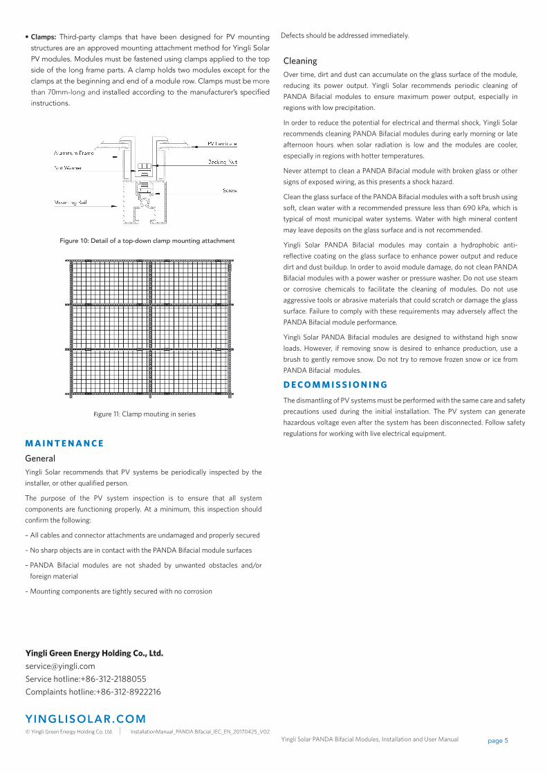
• Clamps: Third-party clamps that have been designed for PV mounting structures are an approved mounting attachment method for Yingli Solar PV modules. Modules must be fastened using clamps applied to the top side of the long frame parts. A clamp holds two modules except for the clamps at the beginning and end of a module row. Clamps must be more
than 70mm-long and installed according to the manufacturer’s specified instructions.
Figure 10: Detail of a top-down clamp mounting attachment
Figure 11: Clamp mouting in series
M A I N T E N A N C E
GeneralYingli Solar recommends that PV systems be periodically inspected by the installer, or other qualified person.
The purpose of the PV system inspection is to ensure that all system components are functioning properly. At a minimum, this inspection should confirm the following:
– All cables and connector attachments are undamaged and properly secured
– No sharp objects are in contact with the PANDA Bifacial module surfaces
– PANDA Bifacial modules are not shaded by unwanted obstacles and/or foreign material
– Mounting components are tightly secured with no corrosion
Defects should be addressed immediately.
CleaningOver time, dirt and dust can accumulate on the glass surface of the module, reducing its power output. Yingli Solar recommends periodic cleaning of PANDA Bifacial modules to ensure maximum power output, especially in regions with low precipitation.
In order to reduce the potential for electrical and thermal shock, Yingli Solar recommends cleaning PANDA Bifacial modules during early morning or late afternoon hours when solar radiation is low and the modules are cooler, especially in regions with hotter temperatures.
Never attempt to clean a PANDA Bifacial module with broken glass or other signs of exposed wiring, as this presents a shock hazard.
Clean the glass surface of the PANDA Bifacial modules with a soft brush using soft, clean water with a recommended pressure less than 690 kPa, which is typical of most municipal water systems. Water with high mineral content may leave deposits on the glass surface and is not recommended.
Yingli Solar PANDA Bifacial modules may contain a hydrophobic anti-reflective coating on the glass surface to enhance power output and reduce dirt and dust buildup. In order to avoid module damage, do not clean PANDA Bifacial modules with a power washer or pressure washer. Do not use steam or corrosive chemicals to facilitate the cleaning of modules. Do not use aggressive tools or abrasive materials that could scratch or damage the glass surface. Failure to comply with these requirements may adversely affect the PANDA Bifacial module performance.
Yingli Solar PANDA Bifacial modules are designed to withstand high snow loads. However, if removing snow is desired to enhance production, use a brush to gently remove snow. Do not try to remove frozen snow or ice from PANDA Bifacial modules.
D E C O M M I S S I O N I N G
The dismantling of PV systems must be performed with the same care and safety precautions used during the initial installation. The PV system can generate hazardous voltage even after the system has been disconnected. Follow safety regulations for working with live electrical equipment.
Yingli Green Energy Holding Co., Ltd. [email protected] Service hotline:+86-312-2188055Complaints hotline:+86-312-8922216
yinglisolar.com © Yingli Green Energy Holding Co. Ltd. InstallationManual_PANDA Bifacial_IEC_EN_20170425_V02
Yingli Solar PANDA Bifacial Modules, Installation and User Manual page 6
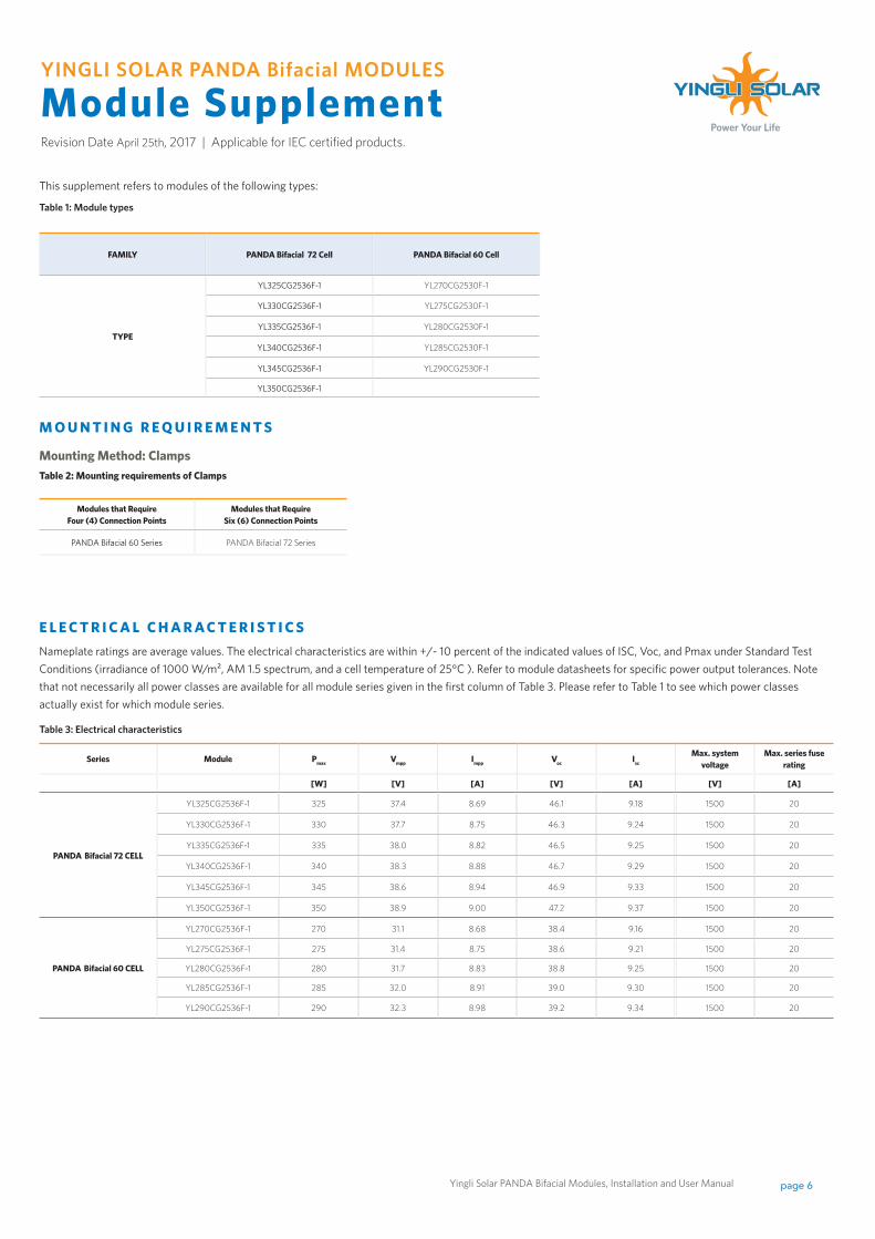
This supplement refers to modules of the following types:
Table 1: Module types
FAMILY PANDA Bifacial 72 Cell PANDA Bifacial 60 Cell
TYPE
YL325CG2536F-1 YL270CG2530F-1
YL330CG2536F-1 YL275CG2530F-1
YL335CG2536F-1 YL280CG2530F-1
YL340CG2536F-1 YL285CG2530F-1
YL345CG2536F-1 YL290CG2530F-1
YL350CG2536F-1
YINGLI SOLAR PANDA Bifacial MODULES
Module SupplementRevision Date April 25th, 2017 | Applicable for IEC certified products.
File name: Corporate Logo with Tagline / Vertical.ai
E L E C T R I C A L C H A R A C T E R I S T I C SNameplate ratings are average values. The electrical characteristics are within +/- 10 percent of the indicated values of ISC, Voc, and Pmax under Standard Test Conditions (irradiance of 1000 W/m², AM 1.5 spectrum, and a cell temperature of 25°C ). Refer to module datasheets for specific power output tolerances. Note that not necessarily all power classes are available for all module series given in the first column of Table 3. Please refer to Table 1 to see which power classes actually exist for which module series.
M O U N T I N G R E Q U I R E M E N T S
Mounting Method: ClampsTable 2: Mounting requirements of Clamps
Modules that Require Four (4) Connection Points
Modules that Require Six (6) Connection Points
PANDA Bifacial 60 Series PANDA Bifacial 72 Series
Table 3: Electrical characteristics
Series Module Pmax Vmpp Impp Voc Isc
Max. system voltage
Max. series fuse rating
[W] [V] [A] [V] [A] [V] [A]
PANDA Bifacial 72 CELL
YL325CG2536F-1 325 37.4 8.69 46.1 9.18 1500 20
YL330CG2536F-1 330 37.7 8.75 46.3 9.24 1500 20
YL335CG2536F-1 335 38.0 8.82 46.5 9.25 1500 20
YL340CG2536F-1 340 38.3 8.88 46.7 9.29 1500 20
YL345CG2536F-1 345 38.6 8.94 46.9 9.33 1500 20
YL350CG2536F-1 350 38.9 9.00 47.2 9.37 1500 20
PANDA Bifacial 60 CELL
YL270CG2536F-1 270 31.1 8.68 38.4 9.16 1500 20
YL275CG2536F-1 275 31.4 8.75 38.6 9.21 1500 20
YL280CG2536F-1 280 31.7 8.83 38.8 9.25 1500 20
YL285CG2536F-1 285 32.0 8.91 39.0 9.30 1500 20
YL290CG2536F-1 290 32.3 8.98 39.2 9.34 1500 20
Yingli Solar PANDA Bifacial Modules, Installation and User Manual page 7
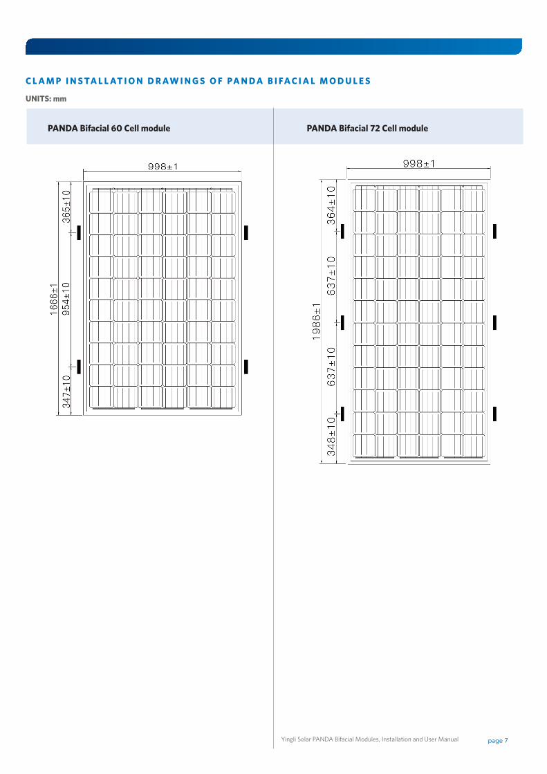
PANDA Bifacial 60 Cell module PANDA Bifacial 72 Cell module
C L A M P I N S TA L L AT I O N D R AW I N G S O F PA N D A B I FA C I A L M O D U L E S
UNITS: mm