Embed Size (px)
Citation preview
Yielding and flow of foamed metakaolin pastes
Lucie Ducloue, Olivier Pitois, Laurent Tocquer, Julie Goyon, Guillaume
Ovarlez
To cite this version:
Lucie Ducloue, Olivier Pitois, Laurent Tocquer, Julie Goyon, Guillaume Ovarlez. Yielding andflow of foamed metakaolin pastes. 2015. <hal-01205614>
HAL Id: hal-01205614
https://hal.archives-ouvertes.fr/hal-01205614
Submitted on 1 Oct 2015
HAL is a multi-disciplinary open accessarchive for the deposit and dissemination of sci-entific research documents, whether they are pub-lished or not. The documents may come fromteaching and research institutions in France orabroad, or from public or private research centers.
L’archive ouverte pluridisciplinaire HAL, estdestinee au depot et a la diffusion de documentsscientifiques de niveau recherche, publies ou non,emanant des etablissements d’enseignement et derecherche francais ou etrangers, des laboratoirespublics ou prives.
Yielding and flow of foamed metakaolin pastes
Lucie Duclouea,∗, Olivier Pitoisb, Laurent Tocquerb, Julie Goyonb,Guillaume Ovarlezc
aManchester Centre for Nonlinear Dynamics and School of Physics and Astronomy,University of Manchester,Manchester M13 9PL, United Kingdom
bUniversite Paris-Est, Laboratoire Navier, UMR 8205 CNRS - Ecole des PontsParisTech - IFSTTAR, 77420 Champs-sur-Marne, France
cUniversite de Bordeaux, LOF, UMR 5258 CNRS - Solvay, 33608 Pessac, France
Abstract
Metakaolin is a broadly used industrial raw material, with applications inthe production of ceramics and geopolymers, and the partial replacement ofPortland cement. The early stages of the manufacturing of some of thesematerials require the preparation and processing of a foamed metakaolin-based slurry. In this study, we propose to investigate the rheology of a foamedmetakaolin-based fresh paste by performing well-controlled experiments. Wework with a non-reactive metakaolin paste containing surfactant, in which wedisperse bubbles of known radius at a chosen volume fraction. We performrheometry measurements to characterize the minimum stress required forthe foamed materials to flow (yield stress), and the dissipation occurringduring flow. We show that the yield stress of the foamed samples is equal tothe one of the metakaolin paste, and that dissipation during flow increasesquadratically with the bubble volume fraction. Comparison with yieldingand flow of model foamed yield stress fluids allows us to understand theseresults in terms of coupling between the bubbles’ surface tension and themetakaolin paste’s rheology.
Keywords: metakaolin, bubbles, rheology, yield stress, viscosity
1. Introduction
Metakaolin is a dehydroxylated clay (Bich et al., 2009) with a high poz-zolanic activity, making it widely used as a raw industrial material. The alkaliactivation of alumina- and silica-rich metakaolin leads to the formation of a
∗corresponding authorEmail address: [email protected] (Lucie Ducloue)
Preprint submitted to Journal of the American Ceramic Society October 1, 2015
three-dimensional aluminosilicate network. The resulting product, called ageopolymer (Davidovits, 1991) is a strong and durable cementitious materialwhich hardens at moderate temperature, thus being relatively low energyconsuming. For that reason, geopolymers are suggested as a sustainable al-ternative to other materials that require processing at very high temperature,among which some ceramic parts (Davidovits, 1991) and Portland cement,which is the most common binder for mortar and concrete. Metakaolin hasalso been successfully used as a partial replacement for Portland cement inregular construction materials, with benefits including an increase in theearly age strength, enhanced durability and a better resistance to chemicalattacks compared to ordinary Portland cement-based materials (Sabir et al.,2001).
In the context of a general industrial effort to develop building materialswith lower environmental impact, foamed geopolymer concrete combines theadvantages of a low energy consuming geopolymer matrix with the benefitsof adding gas bubbles which will make the resulting concrete lightweight andthermally insulating (Ramamurthy et al., 2009; Zhang et al., 2014). Thereare two main routes to produce foamed geopolymer concrete: gas bubblescan either be generated by an in-situ chemical reaction (Prud’Homme et al.,2011; Masi et al., 2014) or can be added mechanically, either through strongagitation that entraps air in the paste (Cilla et al., 2014) or by mixing witha foam concentrate (Zhang et al., 2014). For high temperature applications,this foamed geopolymer can then be sintered, leading to the formation of afoamed ceramic (Bell and Kriven, 2009) which can be used to filter hot gasesor to make thermal insulating tiles for extreme conditions (Montanaro et al.,1998).
Whether producing a foamed geopolymer or a foamed ceramic, the size,volume fraction and distribution of the gas bubbles in the final foamed claymaterial are crucial to the application the material is designed for (Gladand Kriven, 2015). Therefore, the incorporation and the preservation of thegas bubbles in the mineral paste when elaborating the material is essential.From a rheological point of view, the paste is a complex fluid, which onlyflows if the stress applied to it is larger than a critical value: the yield stressof the paste. Above that yield stress, the paste flows with a viscosity whichdepends on the flow rate applied. The interplay of the complex rheology ofthe mineral paste with the bubbles will determine the stability of the bubblesentrapped in the paste, but also the rheology of the foamed material. As thedevelopment of materials such as geopolymer foamed concrete is currentlyin the relatively early stages of technological maturity, understanding this
2
behavior is necessary to elaborate optimized processes and materials. Thosestability and rheological issues should be tackled as a complement to thestudy of the chemical reactions and functional properties.
In this paper, we propose to shed light on the flow properties of just mixedfoamed clay pastes by investigating the rheological behavior of a metakaolinpaste containing air bubbles. We work with a non-reactive material contain-ing surfactant to stabilize the mechanically added air bubbles, and focus onhow the behavior of the paste is modified by the addition of bubbles of aknown radius at a given volume fraction. This question is for instance ofinterest to design efficient processes to cast or pump a geopolymer foamedconcrete. The first section of this paper presents in more detail our exper-imental system and the rheometry procedure used to characterize it. Thefollowing section presents the results we have obtained for two rheologicalproperties relevant for bubble stability and material workability: the min-imal stress required to induce flow and the dissipation during flow of thefoamed metakaolin pastes. In the third and last section, those results arediscussed in the light of previous experiments done on foamed samples ofsimple yield stress fluids.
2. Experimental procedure
We prepare model samples of foamed metakaolin paste by dispersing bub-bles of well defined radius at a chosen volume fraction in a concentratedmetakaolin paste. To achieve such a level of control on our systems, weprepare a very concentrated metakaolin paste containing no bubbles, whichwe then mix with a separately produced monodisperse aqueous foam. Thisprocedure, which is presented below after the details of the materials used,allows us to control the bubble size and the gas volume fraction of the foamedmetakaolin samples throughout the process of mixing and characterization.The volume fraction of entrapped air, φ, is varied in the range 0-50%, whichis the void volume fraction commonly found in the production of foamedgeopolymer concrete by mechanical agitation or mixing with a foam (Zhanget al., 2014). Sample preparation and characterization is done at 25C.
2.1. Metakaolin paste
The metakaolin paste which will be mixed with the foam (”stock paste”)is a dispersion of a fine metakaolin (Argical M1200-S, AGS mineraux - Imerys
3
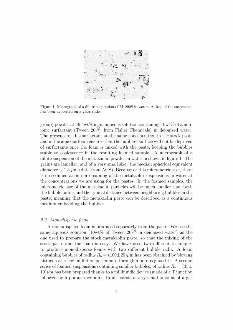
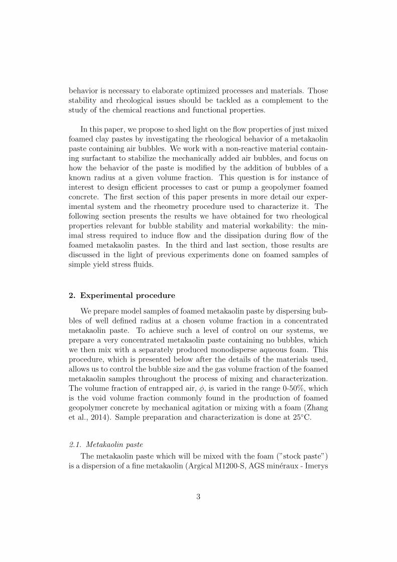
Figure 1: Micrograph of a dilute suspension of M1200S in water. A drop of the suspensionhas been deposited on a glass slide.
group) powder at 46.4wt% in an aqueous solution containing 10wt% of a non-ionic surfactant (Tween 20 R©, from Fisher Chemicals) in deionized water.The presence of this surfactant at the same concentration in the stock pasteand in the aqueous foam ensures that the bubbles’ surface will not be deprivedof surfactants once the foam is mixed with the paste, keeping the bubblesstable to coalescence in the resulting foamed sample. A micrograph of adilute suspension of the metakaolin powder in water in shown in figure 1. Thegrains are lamellar, and of a very small size: the median spherical equivalentdiameter is 1.3 µm (data from AGS). Because of this micrometric size, thereis no sedimentation nor creaming of the metakaolin suspensions in water atthe concentrations we are using for the pastes. In the foamed samples, themicrometric size of the metakaolin particles will be much smaller than boththe bubble radius and the typical distance between neighboring bubbles in thepaste, meaning that the metakaolin paste can be described as a continuousmedium embedding the bubbles.
2.2. Monodisperse foam
A monodisperse foam is produced separately from the paste. We use thesame aqueous solution (10wt% of Tween 20 R© in deionized water) as theone used to prepare the stock metakaolin paste, so that the mixing of thestock paste and the foam is easy. We have used two different techniquesto produce monodisperse foams with two different bubble radii. A foamcontaining bubbles of radius Rb = (100±20)µm has been obtained by blowingnitrogen at a few milliliters per minute through a porous glass frit. A secondseries of foamed suspensions containing smaller bubbles, of radius Rb = (35±10)µm has been prepared thanks to a millifluidic device (made of a T junctionfollowed by a porous medium). In all foams, a very small amount of a gas
4
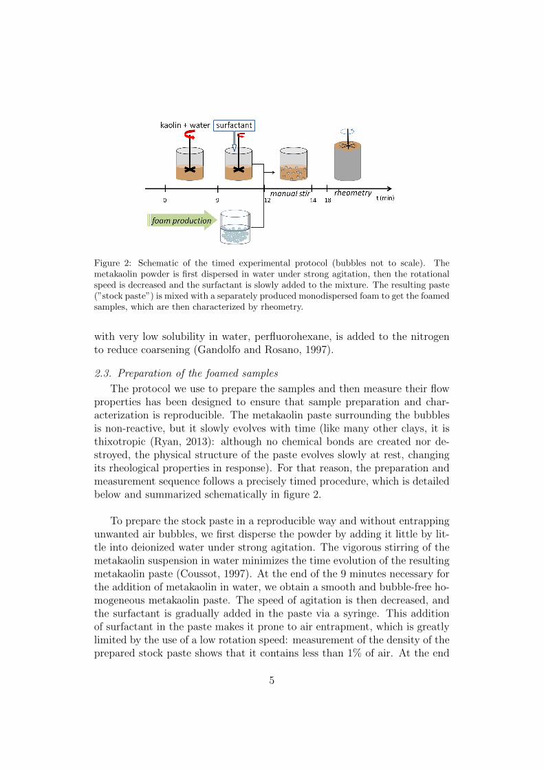
Figure 2: Schematic of the timed experimental protocol (bubbles not to scale). Themetakaolin powder is first dispersed in water under strong agitation, then the rotationalspeed is decreased and the surfactant is slowly added to the mixture. The resulting paste(”stock paste”) is mixed with a separately produced monodispersed foam to get the foamedsamples, which are then characterized by rheometry.
with very low solubility in water, perfluorohexane, is added to the nitrogento reduce coarsening (Gandolfo and Rosano, 1997).
2.3. Preparation of the foamed samples
The protocol we use to prepare the samples and then measure their flowproperties has been designed to ensure that sample preparation and char-acterization is reproducible. The metakaolin paste surrounding the bubblesis non-reactive, but it slowly evolves with time (like many other clays, it isthixotropic (Ryan, 2013): although no chemical bonds are created nor de-stroyed, the physical structure of the paste evolves slowly at rest, changingits rheological properties in response). For that reason, the preparation andmeasurement sequence follows a precisely timed procedure, which is detailedbelow and summarized schematically in figure 2.
To prepare the stock paste in a reproducible way and without entrappingunwanted air bubbles, we first disperse the powder by adding it little by lit-tle into deionized water under strong agitation. The vigorous stirring of themetakaolin suspension in water minimizes the time evolution of the resultingmetakaolin paste (Coussot, 1997). At the end of the 9 minutes necessary forthe addition of metakaolin in water, we obtain a smooth and bubble-free ho-mogeneous metakaolin paste. The speed of agitation is then decreased, andthe surfactant is gradually added in the paste via a syringe. This additionof surfactant in the paste makes it prone to air entrapment, which is greatlylimited by the use of a low rotation speed: measurement of the density of theprepared stock paste shows that it contains less than 1% of air. At the end
5
of the 3 minutes necessary to add and blend the surfactant into the paste,the paste is mixed with the separately produced foam. This mixing brings inmore aqueous solution, which will lower the final solid content in the pasteof the foamed samples. The mass of added foam is always 6% of the massof prepared stock paste, so that all the foamed metakaolin samples have thesame solid content (44wt%) in the suspending paste surrounding the bub-bles (”suspending paste”). The gas volume fraction in the foamed samples isvaried by changing the wetness of the aqueous foam prior to mixing. The in-corporation of the bubbles in the paste is done by blending for 2 minutes witha spoon, to ensure that stirring occurs both in the vertical and the azimuthaldirections. After mixing, the foamed metakaolin sample is poured in a taredrheometry cup of known volume (61.6 mL). Weighting of the full cup allowsfor the determination of the density of the samples, and hence the volumefraction of entrapped air. The cup is then set in the rheometer and 4 min-utes after pouring the sample in the cup, the mechanical measurements start.
2.4. Rheometry procedure
The characterization of the flow properties of the samples is done by usinga commercial controlled-stress rheometer (Bohlin C-VOR 200), which worksat either set torque or set rotational velocity (thanks to a torque feedbackloop). The rheometer is fitted with a six-bladed vane tool (radius Ri = 12.5mm) in a cup (radius Ro = 18 mm) geometry. The gap Ro − Ri is largerthan several bubble diameters, which ensures that the bulk properties of thefoamed samples are measured. Fine sand paper is glued inside the cup toavoid slippage of the metakaolin paste at the cup wall (Coussot, 2005). Be-cause of the wide gap of the geometry we are using, the shear stress variesalong the radius r in the gap. We compute the shear stress and shear rateat r = Ri from the torque and rotational velocity assuming that the rotatingvane tool is equivalent to a cylinder of same radius Ri. We subtract thecontribution of the end effects at the bottom of the virtual cylinder definedby the vane, and take into account the localization of shear when computingthe flow curve (Coussot, 2005). Throughout the sequence, the free surface ofthe sample is visible, allowing us to check that the bubbles do not coalescenor cream during the measurement.
After the cup is set in the rheometer, the vane tool is slowly inserted,so that the last significant flow undergone by the sample before the startof the rheometry procedure is the one generated when pouring it into thecup. Because of the random nature of this flow, the sample is assumed to behomogeneous and isotropic prior to the start of the measurement sequence.
6
0 , 0 0 , 1 0 , 2 0 , 3 0 , 405
1 01 52 02 53 0
τ (Pa)
γ ( )
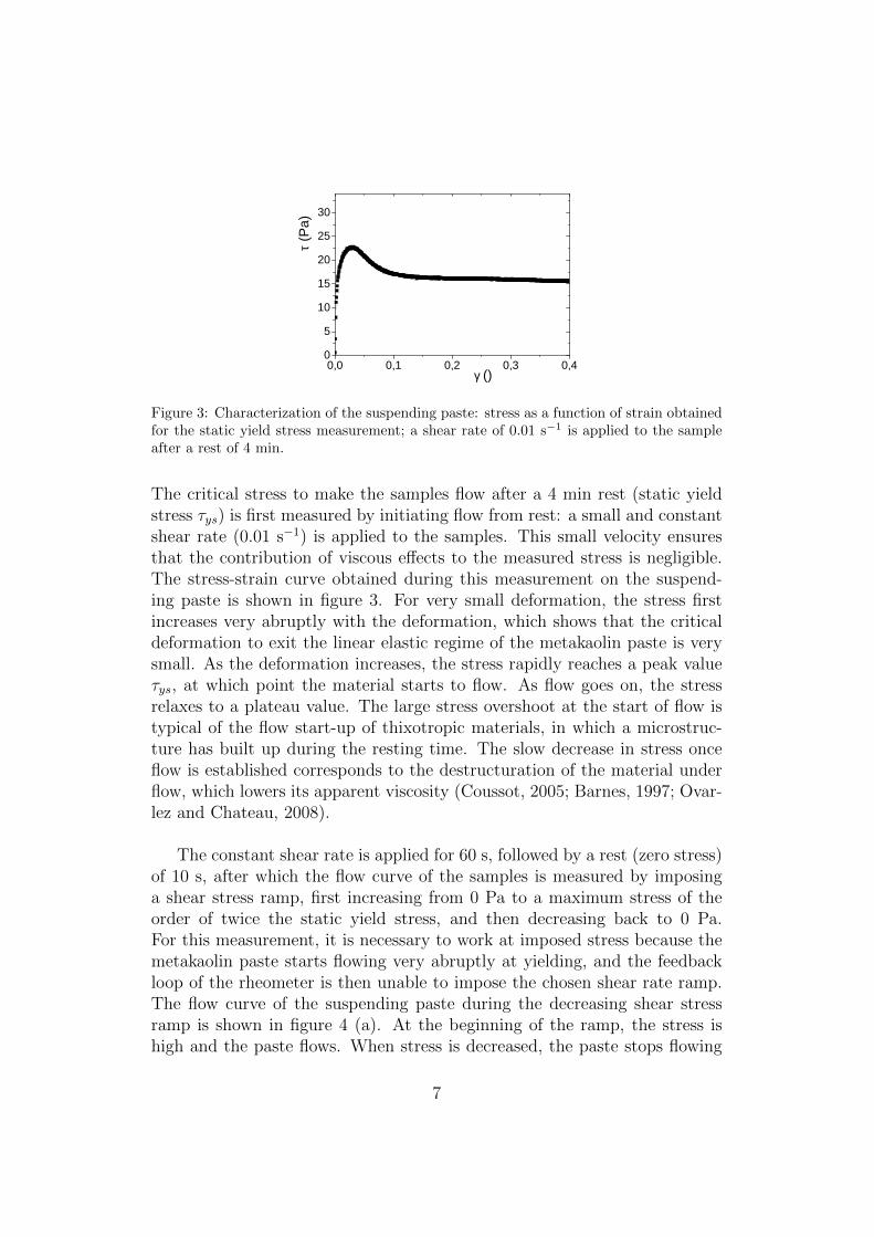
Figure 3: Characterization of the suspending paste: stress as a function of strain obtainedfor the static yield stress measurement; a shear rate of 0.01 s−1 is applied to the sampleafter a rest of 4 min.
The critical stress to make the samples flow after a 4 min rest (static yieldstress τys) is first measured by initiating flow from rest: a small and constantshear rate (0.01 s−1) is applied to the samples. This small velocity ensuresthat the contribution of viscous effects to the measured stress is negligible.The stress-strain curve obtained during this measurement on the suspend-ing paste is shown in figure 3. For very small deformation, the stress firstincreases very abruptly with the deformation, which shows that the criticaldeformation to exit the linear elastic regime of the metakaolin paste is verysmall. As the deformation increases, the stress rapidly reaches a peak valueτys, at which point the material starts to flow. As flow goes on, the stressrelaxes to a plateau value. The large stress overshoot at the start of flow istypical of the flow start-up of thixotropic materials, in which a microstruc-ture has built up during the resting time. The slow decrease in stress onceflow is established corresponds to the destructuration of the material underflow, which lowers its apparent viscosity (Coussot, 2005; Barnes, 1997; Ovar-lez and Chateau, 2008).
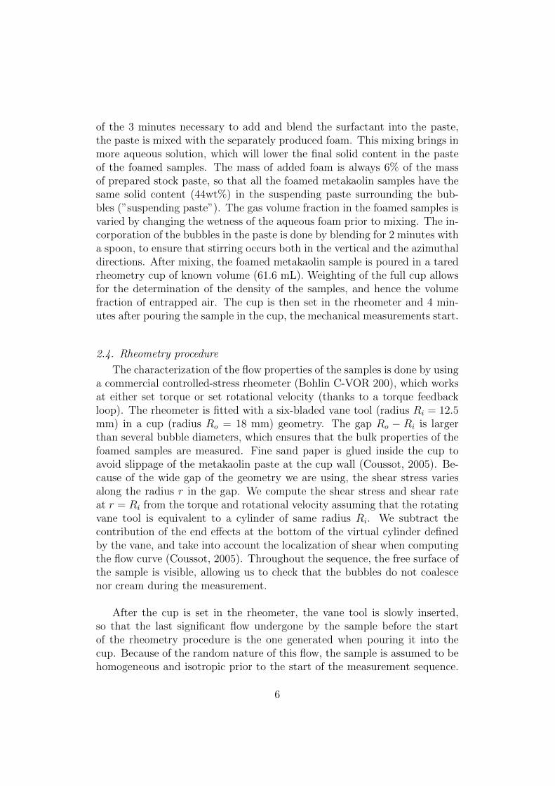
The constant shear rate is applied for 60 s, followed by a rest (zero stress)of 10 s, after which the flow curve of the samples is measured by imposinga shear stress ramp, first increasing from 0 Pa to a maximum stress of theorder of twice the static yield stress, and then decreasing back to 0 Pa.For this measurement, it is necessary to work at imposed stress because themetakaolin paste starts flowing very abruptly at yielding, and the feedbackloop of the rheometer is then unable to impose the chosen shear rate ramp.The flow curve of the suspending paste during the decreasing shear stressramp is shown in figure 4 (a). At the beginning of the ramp, the stress ishigh and the paste flows. When stress is decreased, the paste stops flowing
7
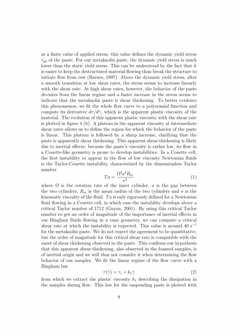
at a finite value of applied stress: this value defines the dynamic yield stressτyd of the paste. For our metakaolin paste, the dynamic yield stress is muchlower than the static yield stress. This can be understood by the fact that itis easier to keep the destructured material flowing than break the structure toinitiate flow from rest (Barnes, 1997). Above the dynamic yield stress, aftera smooth transition at low shear rates, the stress seems to increase linearlywith the shear rate. At high shear rates, however, the behavior of the pastedeviates from the linear regime and a faster increase in the stress seems toindicate that the metakaolin paste is shear thickening. To better evidencethis phenomenon, we fit the whole flow curve to a polynomial function andcompute its derivative dτ/dγ, which is the apparent plastic viscosity of thematerial. The evolution of this apparent plastic viscosity with the shear rateis plotted in figure 4 (b). A plateau in the apparent viscosity at intermediateshear rates allows us to define the region for which the behavior of the pasteis linear. This plateau is followed by a sharp increase, clarifying that thepaste is apparently shear thickening. This apparent shear-thickening is likelydue to inertial effects: because the paste’s viscosity is rather low, its flow ina Couette-like geometry is prone to develop instabilities. In a Couette cell,the first instability to appear in the flow of low viscosity Newtonian fluidsis the Taylor-Couette instability, characterized by the dimensionless Taylornumber
Ta =Ω2a3Rm
ν2(1)
where Ω is the rotation rate of the inner cylinder, a is the gap betweenthe two cylinders, Rm is the mean radius of the two cylinders and ν is thekinematic viscosity of the fluid. Ta is only rigorously defined for a Newtonianfluid flowing in a Couette cell, in which case the instability develops above acritical Taylor number of 1712 (Guyon, 2001). By using this critical Taylornumber to get an order of magnitude of the importance of inertial effects inour Bingham fluids flowing in a vane geometry, we can compute a criticalshear rate at which the instability is expected. This value is around 40 s−1
for the metakaolin paste. We do not expect the agreement to be quantitative,but the order of magnitude for this critical shear rate is compatible with theonset of shear thickening observed in the paste. This confirms our hypothesisthat this apparent shear-thickening, also observed in the foamed samples, isof inertial origin and we will thus not consider it when determining the flowbehavior of our samples. We fit the linear regime of the flow curve with aBingham law
τ(γ) = τc + k1γ (2)
from which we extract the plastic viscosity k1 describing the dissipation inthe samples during flow. This law for the suspending paste is plotted with
8
0 2 0 4 0 6 0 8 0 1 0 0 1 2 00
5
1 0
1 5
2 0
( a )
τ (Pa)
d γ / d t ( s - 1 )0 2 0 4 0 6 0 8 0 1 0 0 1 2 00 , 0
0 , 1
0 , 2
0 , 3
0 , 4
( b )
d γ / d t ( s - 1 )
dτ/(dγ
/dt) (P
as)
Figure 4: Characterization of the flow behavior of the suspending paste: (a) Stress as afunction of shear rate obtained during the decreasing shear stress ramp. The dashed lineis a linear fit to the data in the region of constant plastic viscosity. (b) Derivative of theflow curve with respect to the flow rate. A viscosity plateau is observed at intermediateshear rates. The onset of shear thickening at higher flow rates is clearly visible.
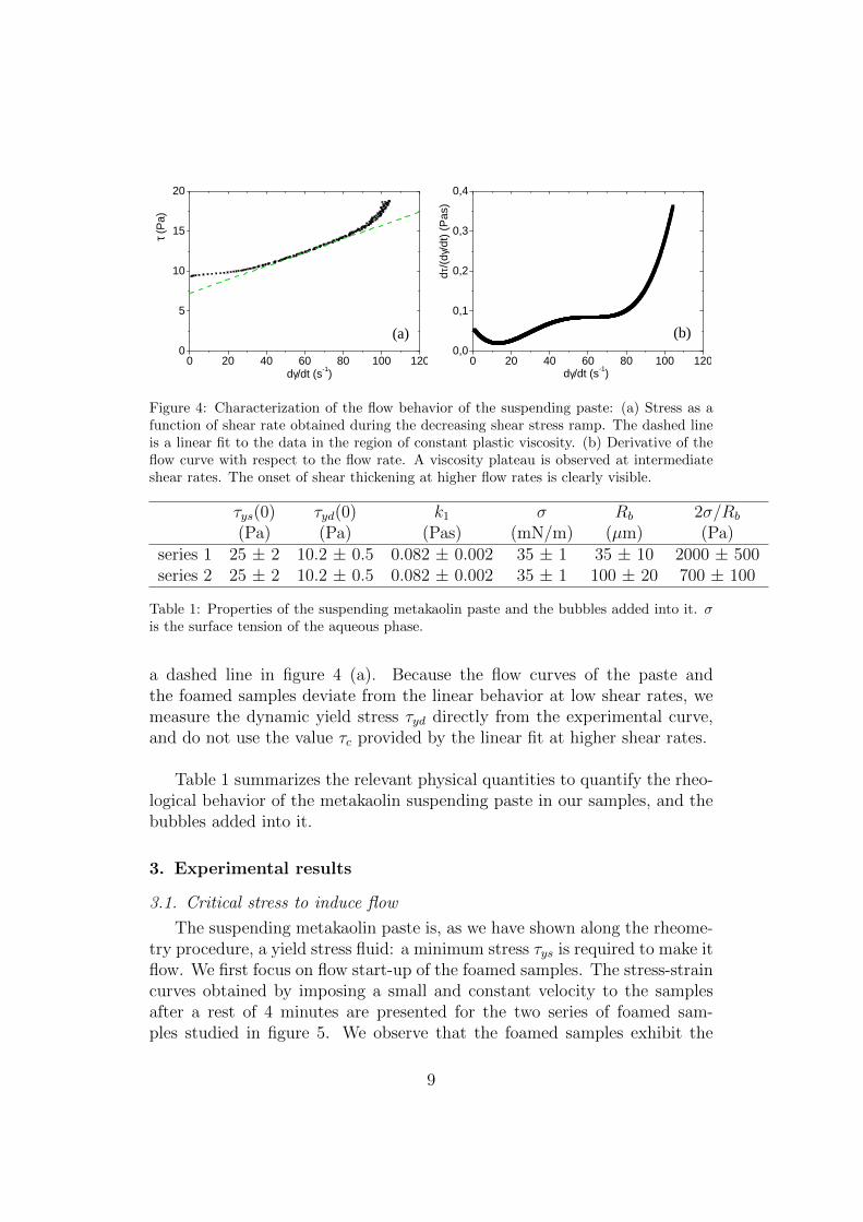
τys(0) τyd(0) k1 σ Rb 2σ/Rb
(Pa) (Pa) (Pas) (mN/m) (µm) (Pa)series 1 25 ± 2 10.2 ± 0.5 0.082 ± 0.002 35 ± 1 35 ± 10 2000 ± 500series 2 25 ± 2 10.2 ± 0.5 0.082 ± 0.002 35 ± 1 100 ± 20 700 ± 100
Table 1: Properties of the suspending metakaolin paste and the bubbles added into it. σis the surface tension of the aqueous phase.
a dashed line in figure 4 (a). Because the flow curves of the paste andthe foamed samples deviate from the linear behavior at low shear rates, wemeasure the dynamic yield stress τyd directly from the experimental curve,and do not use the value τc provided by the linear fit at higher shear rates.
Table 1 summarizes the relevant physical quantities to quantify the rheo-logical behavior of the metakaolin suspending paste in our samples, and thebubbles added into it.
3. Experimental results
3.1. Critical stress to induce flow
The suspending metakaolin paste is, as we have shown along the rheome-try procedure, a yield stress fluid: a minimum stress τys is required to make itflow. We first focus on flow start-up of the foamed samples. The stress-straincurves obtained by imposing a small and constant velocity to the samplesafter a rest of 4 minutes are presented for the two series of foamed sam-ples studied in figure 5. We observe that the foamed samples exhibit the
9
0 , 0 0 , 1 0 , 2 0 , 3 0 , 405
1 01 52 02 53 0
( a )
τ (Pa)
γ ( )
0 % 1 3 % 1 7 % 2 4 % 2 8 % 3 9 % 4 0 % 4 2 % 4 6 % 6
8
1 0
1 2
1 4
τ y d ( P a )
0 , 0 0 , 1 0 , 2 0 , 3 0 , 405
1 01 52 02 53 0
( b )
τ (Pa)
γ ( )
0 % 1 2 % 3 0 % 3 3 % 4 3 %
6
8
1 0
1 2
1 4τ y d ( P a )
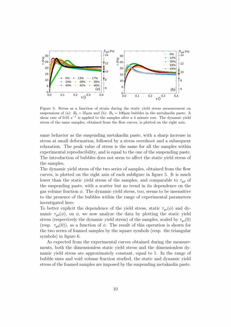
Figure 5: Stress as a function of strain during the static yield stress measurement onsuspensions of (a): Rb = 35µm and (b): Rb = 100µm bubbles in the metakaolin paste. Ashear rate of 0.01 s−1 is applied to the samples after a 4 minute rest. The dynamic yieldstress of the same samples, obtained from the flow curves, is plotted on the right axis.
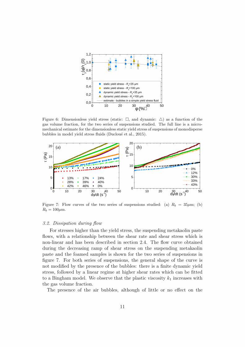
same behavior as the suspending metakaolin paste, with a sharp increase instress at small deformation, followed by a stress overshoot and a subsequentrelaxation. The peak value of stress is the same for all the samples withinexperimental reproducibility, and is equal to the one of the suspending paste.The introduction of bubbles does not seem to affect the static yield stress ofthe samples.The dynamic yield stress of the two series of samples, obtained from the flowcurves, is plotted on the right axis of each subfigure in figure 5. It is muchlower than the static yield stress of the samples, and comparable to τyd ofthe suspending paste, with a scatter but no trend in its dependence on thegas volume fraction φ. The dynamic yield stress, too, seems to be insensitiveto the presence of the bubbles within the range of experimental parametersinvestigated here.To better explicit the dependence of the yield stress, static τys(φ) and dy-namic τyd(φ), on φ, we now analyze the data by plotting the static yieldstress (respectively the dynamic yield stress) of the samples, scaled by τys(0)(resp. τyd(0)), as a function of φ. The result of this operation is shown forthe two series of foamed samples by the square symbols (resp. the triangularsymbols) in figure 6.
As expected from the experimental curves obtained during the measure-ments, both the dimensionless static yield stress and the dimensionless dy-namic yield stress are approximately constant, equal to 1. In the range ofbubble sizes and void volume fraction studied, the static and dynamic yieldstress of the foamed samples are imposed by the suspending metakaolin paste.
10
0 1 0 2 0 3 0 4 0 5 00 , 00 , 20 , 40 , 60 , 81 , 01 , 2
R b R b R b R b
τ y(φ)/τ y(0
)
φ (%)
Figure 6: Dimensionless yield stress (static: , and dynamic: 4) as a function of thegas volume fraction, for the two series of suspensions studied. The full line is a micro-mechanical estimate for the dimensionless static yield stress of suspensions of monodispersebubbles in model yield stress fluids (Ducloue et al., 2015).
0 1 0 2 0 3 0 4 0 5 00
5
1 0
1 5
2 0 ( a )
( a )
τ (Pa)
d γ / d t ( s - 1 )
1 3 % 1 7 % 2 4 % 2 8 % 3 9 % 4 0 % 4 2 % 4 6 % 0 %
1 0 2 0 3 0 4 0 5 00
5
1 0
1 5
2 0 ( b )
τ (Pa)
d γ / d t ( s - 1 )
0 % 1 2 % 3 0 % 3 3 % 4 3 %
Figure 7: Flow curves of the two series of suspensions studied: (a) Rb = 35µm; (b)Rb = 100µm.
3.2. Dissipation during flow
For stresses higher than the yield stress, the suspending metakaolin pasteflows, with a relationship between the shear rate and shear stress which isnon-linear and has been described in section 2.4. The flow curve obtainedduring the decreasing ramp of shear stress on the suspending metakaolinpaste and the foamed samples is shown for the two series of suspensions infigure 7. For both series of suspensions, the general shape of the curve isnot modified by the presence of the bubbles: there is a finite dynamic yieldstress, followed by a linear regime at higher shear rates which can be fittedto a Bingham model. We observe that the plastic viscosity k1 increases withthe gas volume fraction.
The presence of the air bubbles, although of little or no effect on the
11
0 5 1 0 1 5 2 0 2 5 3 0 3 5 4 0 4 5 5 00
1
2
3
4 R b R b n n
k n(φ)/k
n(0)
φ
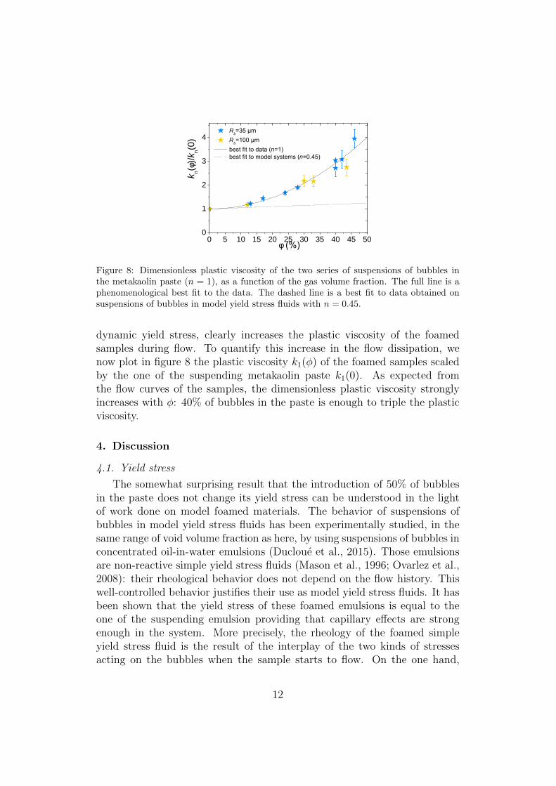
Figure 8: Dimensionless plastic viscosity of the two series of suspensions of bubbles inthe metakaolin paste (n = 1), as a function of the gas volume fraction. The full line is aphenomenological best fit to the data. The dashed line is a best fit to data obtained onsuspensions of bubbles in model yield stress fluids with n = 0.45.
dynamic yield stress, clearly increases the plastic viscosity of the foamedsamples during flow. To quantify this increase in the flow dissipation, wenow plot in figure 8 the plastic viscosity k1(φ) of the foamed samples scaledby the one of the suspending metakaolin paste k1(0). As expected fromthe flow curves of the samples, the dimensionless plastic viscosity stronglyincreases with φ: 40% of bubbles in the paste is enough to triple the plasticviscosity.
4. Discussion
4.1. Yield stress
The somewhat surprising result that the introduction of 50% of bubblesin the paste does not change its yield stress can be understood in the lightof work done on model foamed materials. The behavior of suspensions ofbubbles in model yield stress fluids has been experimentally studied, in thesame range of void volume fraction as here, by using suspensions of bubbles inconcentrated oil-in-water emulsions (Ducloue et al., 2015). Those emulsionsare non-reactive simple yield stress fluids (Mason et al., 1996; Ovarlez et al.,2008): their rheological behavior does not depend on the flow history. Thiswell-controlled behavior justifies their use as model yield stress fluids. It hasbeen shown that the yield stress of these foamed emulsions is equal to theone of the suspending emulsion providing that capillary effects are strongenough in the system. More precisely, the rheology of the foamed simpleyield stress fluid is the result of the interplay of the two kinds of stressesacting on the bubbles when the sample starts to flow. On the one hand,
12
the just yielded suspending fluid exerts a stress on the bubbles, which is ofthe order of magnitude of the fluid’s yield stress and tends to deform thebubbles. On the other hand, capillarity acting on the surface of the bubblestends to minimize to bubbles’ surface area by restoring a spherical shape.The competition of these two mechanisms determines the relative rigidity ofthe bubbles in the just yielded fluid and can be quantified by introducing aplastic capillary number:
Caτ =τy(0)
2σ/Rb
(3)
which is the ratio of the paste yield stress τy(0) to the capillary stress 2σ/Rb.When surface tension forces largely dominate over the yield stress of the sus-pending paste, this capillary number is very low and the bubbles behave asrigid spherical objects in the paste: the stress in the paste is not high enoughto deform them. Note however that they differ from rigid particles in theboundary condition with the fluid, which slips on the bubbles’ surface. Asthe relative importance of surface tension is decreased, Caτ increases and thebubbles become increasingly soft in the paste.
Experiments have shown that below a capillary number of approximately0.1, the yield stress of the samples is not affected by the presence of the bub-bles. For the model systems of monodisperse bubbles in simple yield stressfluids at moderate void volume fraction (well below the percolation thresholdof 64%), it is possible to quantitatively describe and estimate the behaviorof the foamed samples at zero capillary number thanks to homogenizationtechniques (Thy Linh et al., 2013). The result of the estimation is in goodagreement with the experimental data obtained on those model systems andis plotted with a full line in figure 6.In the case of the foamed metakaolin samples, the plastic capillary numbersare 0.01 and 0.03 for the Rb = 35 µm and Rb = 100 µm samples, respectively.From the results on foamed model yield stress fluids, it is then expected thatthe yield stress of the foamed metakaolin samples should not depend on φin the range of volume fractions investigated. The constant yield stress ofthe foamed metakaolin samples shows that their behavior at yielding can bepredicted in the same way as in the model systems, although the rheology ofthe suspending paste is in fact more complicated.Experiments on suspensions of bubbles in model yield stress fluids have alsoshown that for higher plastic capillary numbers, the bubbles become de-formable at yielding of the suspending paste. At the scale of the samples,the softness of the bubbles in the fluid results in a drop of the yield stresswith φ. For large deformations, it has also been observed experimentally
13
that around the same critical capillary number (approximately 0.5 for thesuspensions in the concentrated emulsions), bubbles rupture during mixingwith the paste (Kogan et al., 2013). We did not investigate this regime formetakaolin pastes but the same features can be expected as in model ma-terials. The plastic capillary number is thus also of particular interest inany application requiring the preservation of bubble size during the flow of afoamed metakaolin paste: it gives an estimate of the maximum shear stressthat can be applied to the system without breaking the bubbles.
4.2. Plastic viscosity
The plastic viscosity of the foamed samples dramatically increases withφ for both series of suspensions studied. Interestingly, data for both series ofsuspensions fall on the same curve, which suggests that the bubble size is nota relevant parameter in this viscosity increase. Indeed, as we have explainedin the experimental procedure, the maximum stress applied during the shearstress ramp is about twice the static yield stress. We have shown in thediscussion of the static yield stress measurements that τys(0) is much lowerthan the capillary stress scale, resulting in the bubbles being non-deformablein the suspending metakaolin paste. During the flow curve measurement, thescale of the capillary stress will as a consequence also be very large comparedto the stress scale in the metakoalin paste, meaning that the bubbles remainrigid in the flow within the range of shear rates considered here.
We can then quantify the relative increase in the plastic viscosity for sus-pensions of rigid bubbles in the metakaolin paste by fitting our experimentaldata with a polynomial function. The result of this fit is plotted with afull line in figure 8. The increase for the metakaolin samples is quadratic(equation of the curve: k1(φ)/k1(0) = 1 + 12φ2). For comparison, the rela-tive increase in the plastic viscosity of suspensions of rigid bubbles in modelyield stress fluids is plotted with a dotted line in figure 8 (best fit to theexperimental data obtained on those systems). The increase is much less,but the results on the metakaolin paste and the concentrated emulsion can-not be compared directly because the flow behavior of the emulsion has adifferent power law than the metakaolin paste: its flow curve is well fitted toa Herschel-Bulkley model τ(γ) = τ+kγn with n = 0.45. For this system, themeasured increase in plastic viscosity is linear: k0.45(φ)/k0.45(0) = 1 + 0.49φ.The difference in the rheology of the suspending fluid is significant, and canaccount for the two different responses for the plastic viscosity with the vol-ume fraction. Indeed, the global dissipation in the foamed samples is verysensitive to the way shear is localized between the bubbles during flow, and
14
this local behavior of the suspending fluid is determined by the flow curve ofthe suspending fluid.
5. Conclusions
We have prepared model foamed metakaolin samples, in which the rhe-ology of the suspending metakaolin paste, the bubble size and the bubblevolume fraction are controlled. Two series of samples have been studied,with two different mean bubble radii. We have shown thanks to careful rhe-ology measurements that the static and dynamic yield stress of the foamedsamples are the same as the ones of the suspending paste for the bubblesizes we have investigated. This result can be understood in terms of bubbledeformability, quantified by a capillary number. Our rheology experimentshave also shown that the presence of the bubbles in the paste increases thedissipation during flow. A comparison with suspensions of bubbles in modelyield stress fluids shows that it is also the case in those systems, and thatit is likely that dissipation increases faster for suspensions in fluids of largerplastic index. We have given phenomenological quantification of this dissi-pation in the foamed model fluid and the foamed metakaolin samples.Those results are very promising for the understanding of the rheology offoamed metakaolin pastes, but more importantly have proven that the frame-work developed for model foamed yield stress fluids can also apply to morecomplex systems. This generality could make it relevant to the flow andprocessing of other foamed mineral pastes, such as foamed clay, concrete orplaster slurries.
Ackowledgments
We are thankful to AGS Mineraux (Imerys group) for kindly providingus with the metakaolin as a sample. Financial support from Saint-GobainRecherche (Aubervilliers, France) is gratefully acknowledged.
Barnes, H. A., 1997. Thixotropya review. Journal of Non-Newtonian fluidmechanics 70 (1), 1–33.
Bell, J., Kriven, W., 2009. Preparation of ceramic foams from metakaolin-based geopolymer gels. In: Ceram Eng Sci Proc. Vol. 29. pp. 97–112.
Bich, C., Ambroise, J., Pera, J., 2009. Influence of degree of dehydroxylationon the pozzolanic activity of metakaolin. Applied Clay Science 44 (3), 194–200.
15
Cilla, M. S., Colombo, P., Morelli, M. R., 2014. Geopolymer foams by gel-casting. Ceramics International 40 (4), 5723–5730.
Coussot, P., 1997. Mudflow Rheology and Dynamics. Balkema, Rotterdam.
Coussot, P., 2005. Rheometry of pastes, suspensions, and granular materials:applications in industry and environment. John Wiley & Sons.
Davidovits, J., 1991. Geopolymers. Journal of thermal analysis 37 (8), 1633–1656.
Ducloue, L., Pitois, O., Goyon, J., Chateau, X., Ovarlez, G., 2015. Rheolog-ical behaviour of suspensions of bubbles in yield stress fluids. Journal ofNon-Newtonian Fluid Mechanics 215, 31–39.
Gandolfo, F. G., Rosano, H. L., 1997. Interbubble gas diffusion and thestability of foams. Journal of colloid and interface science 194 (1), 31–36.
Glad, B. E., Kriven, W. M., 2015. Highly porous geopolymers through tem-plating and surface interactions. Journal of the American Ceramic Society.
Guyon, E., 2001. Physical hydrodynamics. Oxford University Press.
Kogan, M., Ducloue, L., Goyon, J., Chateau, X., Pitois, O., Ovarlez, G.,2013. Mixtures of foam and paste: suspensions of bubbles in yield stressfluids. Rheologica Acta 52 (3), 237–253.
Masi, G., Rickard, W. D., Vickers, L., Bignozzi, M. C., Van Riessen, A.,2014. A comparison between different foaming methods for the synthesisof light weight geopolymers. Ceramics International 40 (9), 13891–13902.
Mason, T., Bibette, J., Weitz, D., 1996. Yielding and flow of monodisperseemulsions. Journal of Colloid and Interface Science 179 (2), 439–448.
Montanaro, L., Jorand, Y., Fantozzi, G., Negro, A., 1998. Ceramic foamsby powder processing. Journal of the European Ceramic Society 18 (9),1339–1350.
Ovarlez, G., Chateau, X., 2008. Influence of shear stress applied during flowstoppage and rest period on the mechanical properties of thixotropic sus-pensions. Physical Review E 77 (6), 061403.
Ovarlez, G., Rodts, S., Ragouilliaux, A., Coussot, P., Goyon, J., Colin, A.,2008. Wide-gap couette flows of dense emulsions: Local concentration mea-surements, and comparison between macroscopic and local constitutive
16
law measurements through magnetic resonance imaging. Physical ReviewE 78 (3), 036307.
Prud’Homme, E., Michaud, P., Joussein, E., Peyratout, C., Smith, A.,Rossignol, S., 2011. In situ inorganic foams prepared from various claysat low temperature. Applied Clay Science 51 (1), 15–22.
Ramamurthy, K., Nambiar, E. K., Ranjani, G. I. S., 2009. A classification ofstudies on properties of foam concrete. Cement and concrete composites31 (6), 388–396.
Ryan, W., 2013. Properties of ceramic raw materials. Elsevier.
Sabir, B., Wild, S., Bai, J., 2001. Metakaolin and calcined clays as pozzolansfor concrete: a review. Cement and Concrete Composites 23 (6), 441–454.
Thy Linh, N., Ducloue, L., Ovarlez, G., Chateau, X., 2013. Overall Propertiesof a Soft Porous Material: Surface Tension Effects. Ch. 224, pp. 1895–1902.URL http://ascelibrary.org/doi/abs/10.1061/9780784412992.224
Zhang, Z., Provis, J. L., Reid, A., Wang, H., 2014. Geopolymer foam con-crete: an emerging material for sustainable construction. Construction andBuilding Materials 56, 113–127.
17