Embed Size (px)
Citation preview

YASKAWA Electric Corporation
Robot Controller
DX100,DX200, FS100
Installation Guide

Table of contents 1. Overview .................................................................................................................... 1 2. Necessary Devices ........................................................................................................ 1 3. Introduction Procedure .................................................................................................. 3
3.1. Prior Confirmation Before Connection ......................................................................... 3 3.1.1. Points to be confirmed for robot controller DX100/FS100 .......................................... 3 3.1.2. Points to be confirmed for touch panel display ........................................................ 4
3.2. Connection ............................................................................................................ 7 3.3. CMOS Backup ........................................................................................................ 8
3.3.1. Settings of robot controller DX100/FS100 .............................................................. 8 3.3.2. Settings of touch panel display ............................................................................ 8
4. Q&A ........................................................................................................................ 10

1. Overview This guide explains the introduction procedure for connecting YASKAWA Electric
Corporation robot controller with Pro-face sample project file.
2. Necessary Devices The touch panel displays supported by these sample project files are as follows.
The table below lists the details.
No Manufacturer Series Comment
1 Pro-face GP4000 series Color model only
2 Pro-face GP3000 series Color model only
3 Pro-face LT3000 series Color model only
4 Pro-face SP5000 series Color model only
Refer to the instruction manual and the Web page for the details of supported touch
panel displays.
To use a screen project for GP4000 series in GP3000 series, disable the option "Expand
index count" on the character string table setting screen.
The necessary software and the supported versions, please refer to the technical guide
of the cockpit parts for each model. The protocol and the version necessary for using this sample project file is as follows:
No Manufacturer Product Name Comments
1 Pro-face High-Speed Ethernet Server Driver Ver.1.12.05
Download the High-Speed Ethernet Server Driver Ver. 1.12.05 from the Web page for use.
Download the sample project file from the Web page for use.
* The sample project file to be used differs depending on the model of the touch panel
display to be used or its screen resolution (QVGA, VGA or higher). Check the model
of the touch panel display to be used and its screen resolution before downloading an
sample project file.
Refer to the Web page for the details.
The devices connected with these sample project files are as follows:
No Manufacturer Product Name Model Comment
1 YASWAKA Electric Robot Controller DX100 * High-speed Ethernet
server function
2 YASWAKA Electric Robot Controller DX200 * High-speed Ethernet
server function
1 / 11
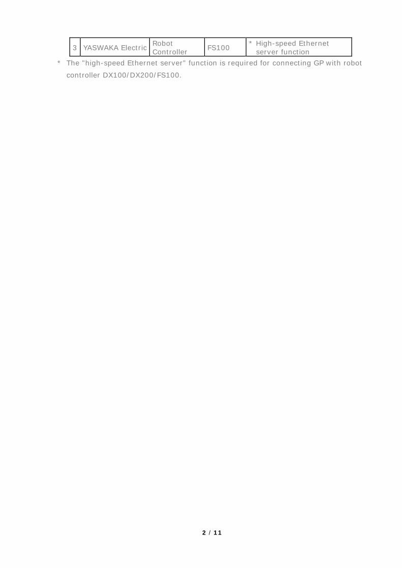
3 YASWAKA Electric Robot Controller FS100 * High-speed Ethernet
server function * The "high-speed Ethernet server" function is required for connecting GP with robot
controller DX100/DX200/FS100.
2 / 11
3. Introduction Procedure
3.1. Prior Confirmation Before Connection The following are the items to be confirmed before connecting robot controller with a
touch panel display to which an sample project file has been transferred.
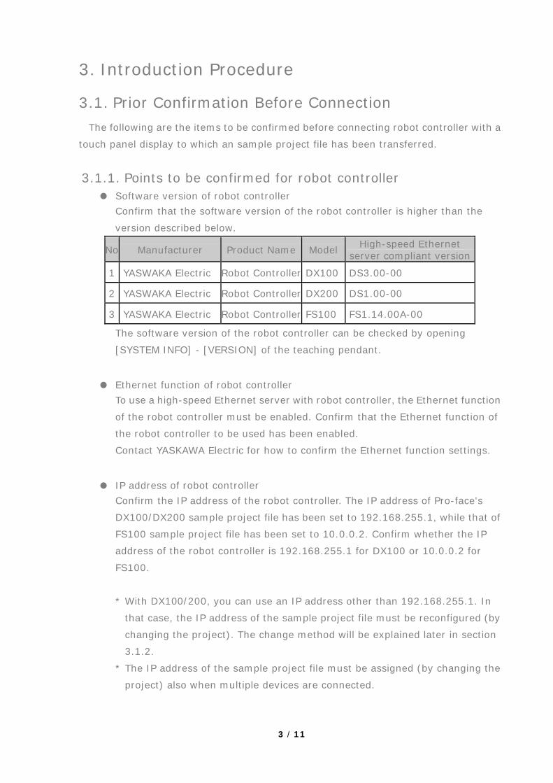
3.1.1. Points to be confirmed for robot controller ● Software version of robot controller
Confirm that the software version of the robot controller is higher than the
version described below.
No Manufacturer Product Name Model High-speed Ethernet server compliant version
1 YASWAKA Electric Robot Controller DX100 DS3.00-00
2 YASWAKA Electric Robot Controller DX200 DS1.00-00
3 YASWAKA Electric Robot Controller FS100 FS1.14.00A-00
The software version of the robot controller can be checked by opening
[SYSTEM INFO] - [VERSION] of the teaching pendant.
● Ethernet function of robot controller To use a high-speed Ethernet server with robot controller, the Ethernet function
of the robot controller must be enabled. Confirm that the Ethernet function of
the robot controller to be used has been enabled.
Contact YASKAWA Electric for how to confirm the Ethernet function settings.
● IP address of robot controller Confirm the IP address of the robot controller. The IP address of Pro-face's
DX100/DX200 sample project file has been set to 192.168.255.1, while that of
FS100 sample project file has been set to 10.0.0.2. Confirm whether the IP
address of the robot controller is 192.168.255.1 for DX100 or 10.0.0.2 for
FS100.
* With DX100/200, you can use an IP address other than 192.168.255.1. In
that case, the IP address of the sample project file must be reconfigured (by
changing the project). The change method will be explained later in section
3.1.2.
* The IP address of the sample project file must be assigned (by changing the
project) also when multiple devices are connected.
3 / 11
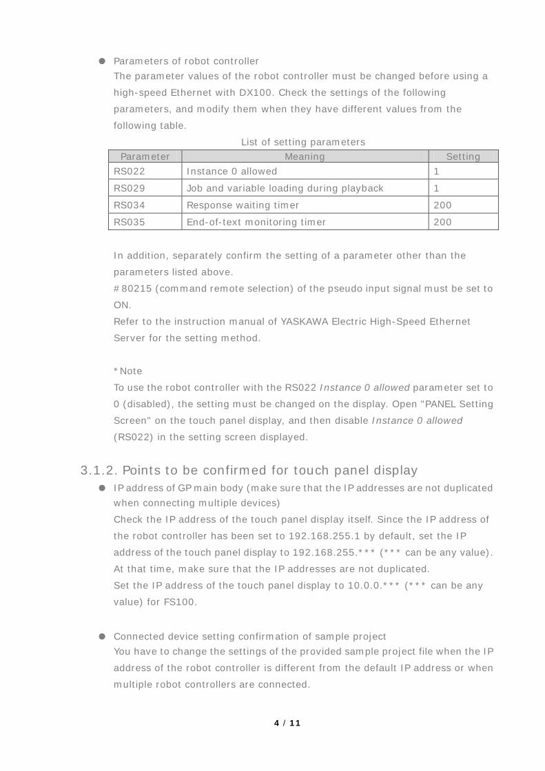
● Parameters of robot controller The parameter values of the robot controller must be changed before using a
high-speed Ethernet with DX100. Check the settings of the following
parameters, and modify them when they have different values from the
following table.
List of setting parameters Parameter Meaning Setting
RS022 Instance 0 allowed 1
RS029 Job and variable loading during playback 1
RS034 Response waiting timer 200
RS035 End-of-text monitoring timer 200
In addition, separately confirm the setting of a parameter other than the
parameters listed above.
#80215 (command remote selection) of the pseudo input signal must be set to
ON.
Refer to the instruction manual of YASKAWA Electric High-Speed Ethernet
Server for the setting method.
*Note
To use the robot controller with the RS022 Instance 0 allowed parameter set to
0 (disabled), the setting must be changed on the display. Open "PANEL Setting
Screen" on the touch panel display, and then disable Instance 0 allowed
(RS022) in the setting screen displayed.
3.1.2. Points to be confirmed for touch panel display ● IP address of GP main body (make sure that the IP addresses are not duplicated
when connecting multiple devices)
Check the IP address of the touch panel display itself. Since the IP address of
the robot controller has been set to 192.168.255.1 by default, set the IP
address of the touch panel display to 192.168.255.*** (*** can be any value).
At that time, make sure that the IP addresses are not duplicated.
Set the IP address of the touch panel display to 10.0.0.*** (*** can be any
value) for FS100.
● Connected device setting confirmation of sample project You have to change the settings of the provided sample project file when the IP
address of the robot controller is different from the default IP address or when
multiple robot controllers are connected.
4 / 11

Device/PLC settings screen
Individual device settings
[When the IP address is changed]
In the sample project, the IP address of the robot controller has been set to
192.168.255.1. When the IP address assigned to the robot controller is other
than 192.168.255.1, you will need to change the project settings.
The following is the change procedure.
Open the sample project with GP-Pro EX.
Double-clicking [Peripheral Settings] - [Device/PLC] in the project window
will open the Device/PLC settings screen.
Click the area surrounded by a red frame (1) in the Device/PLC settings screen.
Clicking (1) will open the Individual Device Settings window. Enter the IP address
of the robot controller to the IP Address field (2) on the Individual Device Settings
screen. After entering the IP address, click OK to close the Individual Device
Settings window. Save the project when you have completed the settings above,
and then transfer the project to the touch panel display.
(1)
(2)
5 / 11

[When multiple devices are connected]
In the sample project, the connected device settings have been made for a
configuration in which a single robot controller is connected with a touch panel
display. When you want to connect multiple robot controllers with a touch panel
display, you will need to change the project settings.
Basically, the operations are the same as that for changing IP address in [When
the IP address is changed] described above.
Open the sample project with GP-Pro EX.
Double-clicking [Peripheral Settings] - [Device/PLC] in the project window will
open the Device/PLC settings screen.
Click the area surrounded by a red frame (1) in the Device/PLC settings screen
for the number of robot controllers to be connected for setting the IP address in
the Individual Device Settings window. Save the project when you have
completed the settings for the required number of devices, and then transfer the
project to the touch panel display.
*Do not change other settings. It may cause a malfunction of the device.
6 / 11

3.2. Connection After confirming that all the items described in “3.1 Prior confirmation before
connection” have been fulfilled, connect the robot controller with the touch panel
display.
The following are the examples of connection configurations.
Connection configuration example (DX100)
Confirm that the robot type setting is correct and the controller usage selections in the
Robot Controller List screen are correct, after power to GP is turned on.
In confirmation of proper connection, open the following screens for checking the data
display.
[Proper connection confirmation]
• Controller list screen Check that the screen is displayed without an error.
• IO monitor (general-purpose input, general-purpose output)
Check that the comments are displayed normally.
• Variable monitor Check that the values are displayed normally.
• Job list of Job list screen Check that the list is displayed normally.
You have completed the connection when you can confirm that the all the screens
above are displayed normally.
7 / 11

3.3. CMOS Backup To use the CMOS backup of the functions provided in the sample project file, you will
need to set up the robot controller and the touch panel display.
Confirm the respective settings.
3.3.1. Settings of robot controller DX100/FS100 Confirm the following settings of the robot controller.
1. Check if S2C680 has been set to 1.
2. Select [SETUP] - [AUTO BACKUP SET], and then check if the device has been set to
RAMDISK.
The batch backup function will not work unless the settings above are made properly.
To use the batch backup, change the settings.
Contact YASKAWA Electric for how to change the settings.
3.3.2. Settings of touch panel display Confirm the following settings of the touch panel display.
1. Set the CF/SD Card setting on the PANEL Setting screen to Use.
2. Set the CMOS Backup setting on the PANEL Setting screen to Enable.
The CMOS backup function will not work correctly unless the settings above are made
properly.
PANEL setting screen (VGA)
PANEL setting screen (VGA)
1
2
8 / 11

PANEL setting screen (QVGA)
1
9 / 11

4. Q&A The following are the possible causes and measures assumed from the occurring
symptom.
Symptom Cause Check points
Connection error is displayed
Failed to communicate properly
• Check the connection (including the cable and HUB)
• Check the IP address of the robot controller and the display
• Check if the IP address setting for the connected device of the sample project is correct
• Check if the selected robot is correct
• Check if the setting of the number of connected devices is correct
A specific button does not work (Grayed out, no response for touch)
The operation of the button is disabled by setting
• Enable the function of the button you want to use Refer to the instruction manual for details
The details of alarm do not work properly (Function is not usable, not displayed)
[CF/SD Card] and [Alarm Detail] in the PANEL Setting screen are set to Disable
• Set [CF/SD Card] and [Alarm Detail] in the PANEL Setting screen to Enable
The alarm file for detailed display is not stored in the CF/SD card
• Store the alarm file for detailed display in the CF/SD card (the alarm file for detailed display can be downloaded from the Web page)
Comments and job list for general-purpose input/output are not displayed
[FILE READ] in the PANEL Setting screen is set to Disable
• Set [FILE READ] in the PANEL Setting screen to Enable
No comments or jobs exists
• Create jobs on the controller side
CMOS batch backup does not work properly
[CF/SD Card] and [CMOS Backup] in the PANEL Setting screen are set to Disable
• Set [CF/SD Card] and [CMOS Backup] in the PANEL Setting screen to Enable
The settings on the controller side are wrong
• Refer to “3.3 CMOS backup”
Connection fails even after settings were made according to the procedure
Former Ethernet server, instead of high-speed Ethernet server, might be enabled
• Ask YASKAWA Electric for confirmation
10 / 11

Symptom Cause Check points
Variable monitor display does not match with teaching pendant Error occurs at specific variable monitor
The setting of RS022 (Instance 0 allowed) of the robot controller and that of Instance 0 allowed on the touch panel display are different
Use the same setting for the robot controller and the touch panel display
Copyright Ⓒ 2013.4 Digital Electronics Corporation. All rights reserved.
11 / 11