Embed Size (px)
Citation preview

YASER SABZEHMEIDANI
YASER SABZEHMEIDANI
A thesis submitted in fulfilment of the
requirements for the award of the degree of
Doctor of Philosophy (Mechanical Engineering)
Faculty of Mechanical Engineering
Universiti Teknologi Malaysia

To my beloved Atena
And my beloved Mother and Father

ACKNOW LEDGEM ENT
Thanks to ALLAH, the Most Gracious and the Most Merciful, All praise and
glory are to Almighty Allah who gave me the courage and patience to accomplish
this research. Without his help and mercy, this wouldn’t be possible.
First and foremost, I would like to express my deep gratitude to my thesis
supervisor Professor Dr. Musa Mailah for all his kindness, assistance and guidance. I
also want to thank my co-supervisor Associated Professor Dr. Mohamed Hussein for
his encouragements and valuable comments. It has been an honour and a privilege to
have the opportunity to work with them.
I wish to thank the Universiti Teknologi Malaysia (UTM) for providing the
facilities to advance the project. Indeed, this research project gave me a valuable
experience and an excellent insight into mechatronic system design. I would like to
further extend my gratitude to all suppliers and technicians who assisted me directly
or indirectly throughout the progress of my project.
Last but not least, I am greatly indebted to my lovely spouse Atena. I would
like to thank her for all encouragements and being beside me. I want to thank my
father and mother for all their supports and kindnesses. Without them I can not be
where I am today.
ABSTRACT
In this research, the development of an in-pipe microrobot system with intelligent active force control (AFC) capability was investigated and presented, including both simulation and experimental studies. Three actuated microrobot mechanisms driven by pneumatic, piezoelectric and voice-coil actuators were modelled and simulated in a constrained environment inside a pipe. The mechanisms were then embedded into the proposed AFC-based control strategy. The worm-like movement of these microrobots with the respective actuators were effectively modelled using the impact drive mechanism (IDM). A classic proportional-integral- derivative (PID) controller was first designed and applied to the microrobot system to follow a desired trajectory in the presence o f disturbances, which may be created due to the frictional force or fluid viscosity inside a pipe. Later, an AFC-based controller was utilized to enhance the system dynamic performance by robustly rejecting the disturbances. To estimate the inertial mass of the AFC loop, artificial intelligence (AI) techniques, namely the variants of fuzzy logic (FL) and iterative learning algorithms (ILA) were explicitly employed. The dynamic response of the fully developed model o f the in-pipe microrobot systems (with three different actuators) subject to various input excitations and disturbances was rigorously explored and numerically experimented. This involved the parametric study and sensitivity analysis to observe and to analyse the effects of a number of influential parameters that were deemed to have positive impact on the system performance. The simulation work was validated through an experimental investigation performed on a rig prototype that employed the voice-coil actuated mechanism to drive the selected AFC-based microrobot scheme, considering the given operating and loading conditions. Full mechatronic approach was adopted in the design of the rig by integrating the related sensors, actuator, mechanical parts and digital controller in a hardware-in-the-loop simulation (HILS) configuration. Parametric study was carried out to complement the simulation counterpart by taking into account the different settings and working environments. From the experimental results, the developed inpipe microrobot system was proven to be effective and robust in its trajectory tracking, in spite o f the existence of various excitation inputs and external disturbances. This implied that the produced experimental responses were in good agreement with those acquired via simulation. The outcomes of the study shall provide a strong foundation for furthering the design of specific in-pipe microrobot applications, such as visual inspection of the inner surface of pipes, fault-diagnostics, obstacle removal and other related tasks.
ABSTRAK
Pembangunan satu sistem robot mikro dalam paip dengan keupayaan kawalan daya aktif pintar (AFC) telah dikaji dan dipersembahkan dalam kajian simulasi dan eksperimen. Tiga jenis mekanisme penggerak robot mikro, iaitu penggerak pneumatic, piezoelektrik, dan voice-coil telah dimasukkan ke dalam strategi kawalan berasaskan-AFC, dan disimulasikan seterusnya dengan mempertimbangkan beberapa operasi dan keadaan beban di dalam persekitaran paip yang terhad. Robot mikro yang mempunyai pergerakan seperti cacing telah dimodelkan secara efektif dengan menggunakan mekanisme penggerak hentaman (IDM). Pengawal klasik berkadaran- kamiran-terbitan (PID) telah direka bentuk terlebih dahulu dan diaplikasikan kepada sistem robot mikro untuk menjejaki trajektori kehendak dengan kehadiran gangguan akibat daripada daya geseran atau kelikatan cecair dalam paip. Kemudian, pengawal berasaskan AFC digunakan untuk meningkatkan prestasi sistem dinamik berdasarkan kekukuhannya untuk menangkis gangguan. Dalam penganggaran jisim inersia bagi gelung AFC, teknik kepintaran buatan (AI) melalui variasi logik kabur (FL) dan algoritma lelaran pembelajaran (ILA) telah digunakan secara khusus. Respons dan gerak balas dinamik bagi model sistem robot mikro dalam-paip yang telah dibangunkan sepenuhnya (dengan tiga penggerak berbeza) dan tertakluk kepada pelbagai ujaan masukan dan gangguan telah dikaji dengan rapi melalui eksperimen numerical (simulasi). Ini melibatkan kajian parametric dan analisis sensitiviti untuk memerhati dan menganalisis kesan beberapa parameter berpengaruh yang dianggap mempunyai kesan positif terhadap prestasis sistem. Sebahagian proses simulasi disahkan melalui kajian eksperimen ke atas prototaip rig yang menggunakan mekanisme penggerak voice-coil untuk memacu robot mikro berasaskan skema AFC, dengan mengambil kira operasi dan beban keadaan yang telah diberikan. Pendekatan mekatronik yang sempurna telah diguna pakai dalam merekabentuk rig, di mana alat penderia, penggerak, bahagian mekanikal dan pengawal digital telah diintegrasikan bersama melalui konfigurasi simulasi perkakasan di dalam gelung (HILS). Kajian parametrik dijalankan untuk mengambil kira persekitaran dan penetapan yang berbeza berpandukan simulasi sebelum ini. Keputusan eksperimen jelas menunjukkan keberkesanan penjejakan trajektori sistem robot mikro dalam- paip yang telah dibangunkan, walaupun terdapatnya pelbagai ujaan masukan dan gangguan luar. Ini dengan jelas menunjukkan bahawa keputusan yang dihasilkan melalui eksperimen fizikal mempunyai banyak persamaan dengna hasil simulasi. Hasil kajian menyediakan satu asas yang kukuh untuk memajukan reka bentuk yang spesifik untuk aplikasi robot mikro dalam paip seperti pemeriksaan visual permukaan paip, diagnostik kegagalan, penyingkiran halangan dan lain-lain tugas yang berkaitan.
CHAPTER TITLE PAGE
DECLARATION ii
DEDICATION iii
ACKNOW LEDGEM ENTS iv
ABSTRACT v
ABSTRAK vi
TABLE OF CONTENTS vii
LIST OF TABLES xi
LIST OF FIGURES xii
LIST OF ABBREVIATIONS xvi
LIST OF SYMBOLS xix
LIST OF APPENDICES xxii
1 INTRODUCTION 1
1.1 Research Background 1
1.2 Problem Statements 2
1.3 Research Objectives 2
1.4 Scope of Research 4
1.5 Research Significance and Contribution 5
1.6 Research Methodology 6
1.6.1 Literature Review 6
1.6.2 Modelling and Simulation 6
1.6.3 Design and Development of Experimental Rig 7
1.6.4 Performance Evaluation and Analysis 9
1.7 Organization of Thesis 11
2 LITERATURE REVIEW & TH EORETICAL 13
FRAM EW ORK
2.1 Introduction 13
2.2 Microrobot Systems 13
2.3 Controllers 32
2.3.1 PID 33
2.3.2 Active Force Control (AFC) 34
2.4 Artificial Intelligence Algorithms 37
2.4.1 Fuzzy Logic (FL) 38
2.4.2 Iterative Learning Algorithm (ILA) 39
2.5 Research Gaps 43
2.6 Summary 44
3 M ODELLING OF IN-PIPE M ICROROBOTS 45
3.1 Introduction 45
3.2 Pneumatic Actuated Micro Robot 45
3.2.1 Operating Principle 46
3.2.2 Mathematical Formulation 47
3.3 Piezoelectric Actuated Micro Robot 50
3.3.1 Operating principle 51
3.3.2 Mathematical Formulation 52
3.4 Voice-Coil Actuated Micro Robot 55
3.4.1 Operating Principle 56
3.4.2 Mathematical Formulation 59
3.5 Actuators Comparative Study 64
3.6 Conclusion 66
4 SIMULATION OF IN-PIPE M ICROROBOTS 68
4.1 Introduction 68
4.2 Control Scheme 68
4.2.1 PID Controller 69
4.2.2 Active Force Control (AFC) 71
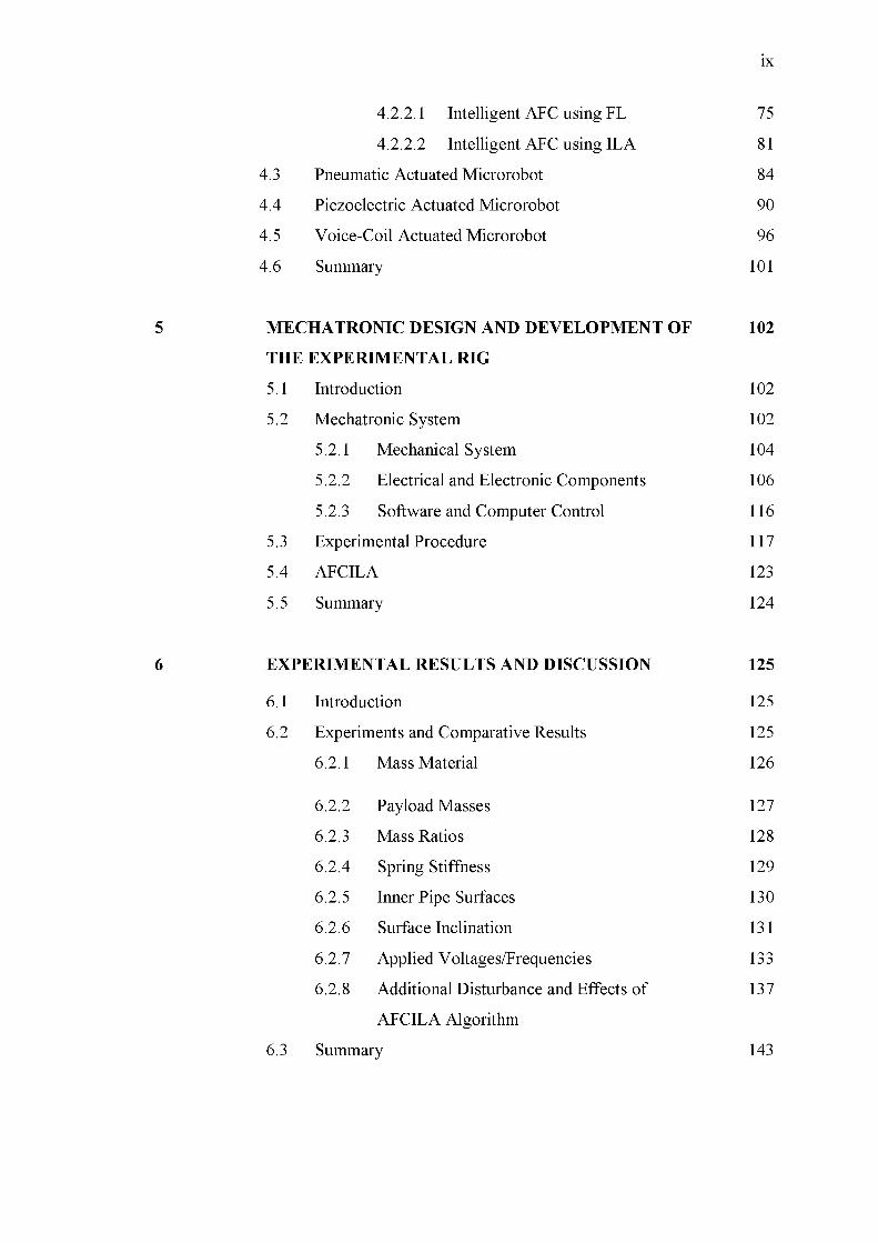
4.2.2.1 Intelligent AFC using FL 75
4.2.2.2 Intelligent AFC using ILA 81
4.3 Pneumatic Actuated Microrobot 84
4.4 Piezoelectric Actuated Microrobot 90
4.5 Voice-Coil Actuated Microrobot 96
4.6 Summary 101
5 M ECHATRONIC DESIGN AND DEVELOPM ENT OF 102
THE EXPERIM ENTAL RIG
5.1 Introduction 102
5.2 Mechatronic System 102
5.2.1 Mechanical System 104
5.2.2 Electrical and Electronic Components 106
5.2.3 Software and Computer Control 116
5.3 Experimental Procedure 117
5.4 AFCILA 123
5.5 Summary 124
6 EXPERIM ENTAL RESULTS AND DISCUSSION 125
6.1 Introduction 125
6.2 Experiments and Comparative Results 125
6.2.1 Mass Material 126
6.2.2 Payload Masses 127
6.2.3 Mass Ratios 128
6.2.4 Spring Stiffness 129
6.2.5 Inner Pipe Surfaces 130
6.2.6 Surface Inclination 131
6.2.7 Applied Voltages/Frequencies 133
6.2.8 Additional Disturbance and Effects of 137
AFCILA Algorithm
6.3 Summary 143

7 CONCLUSION AND FUTURE W ORKS 144
7.1 Conclusion 144
7.2 Recommendation and Future Works 146
REFERENCES
APPENDICES A-C
147
155-173
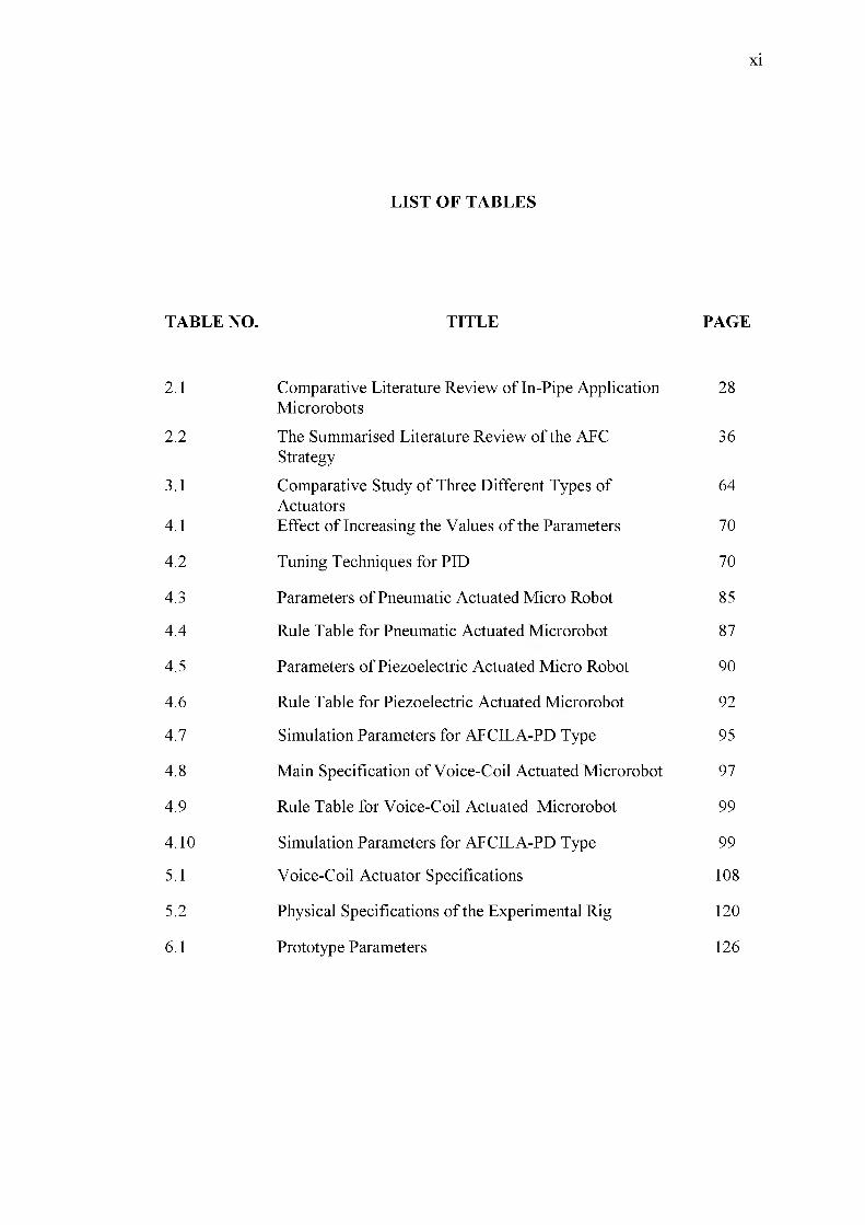
TABLE NO. TITLE PAGE
2.1 Comparative Literature Review of In-Pipe Application Microrobots
28
2.2 The Summarised Literature Review of the AFC Strategy
36
3.1 Comparative Study o f Three Different Types of Actuators
64
4.1 Effect of Increasing the Values of the Parameters 70
4.2 Tuning Techniques for PID 70
4.3 Parameters of Pneumatic Actuated Micro Robot 85
4.4 Rule Table for Pneumatic Actuated Microrobot 87
4.5 Parameters of Piezoelectric Actuated Micro Robot 90
4.6 Rule Table for Piezoelectric Actuated Microrobot 92
4.7 Simulation Parameters for AFCILA-PD Type 95
4.8 Main Specification of Voice-Coil Actuated Microrobot 97
4.9 Rule Table for Voice-Coil Actuated Microrobot 99
4.10 Simulation Parameters for AFCILA-PD Type 99
5.1 Voice-Coil Actuator Specifications 108
5.2 Physical Specifications of the Experimental Rig 120
6.1 Prototype Parameters 126
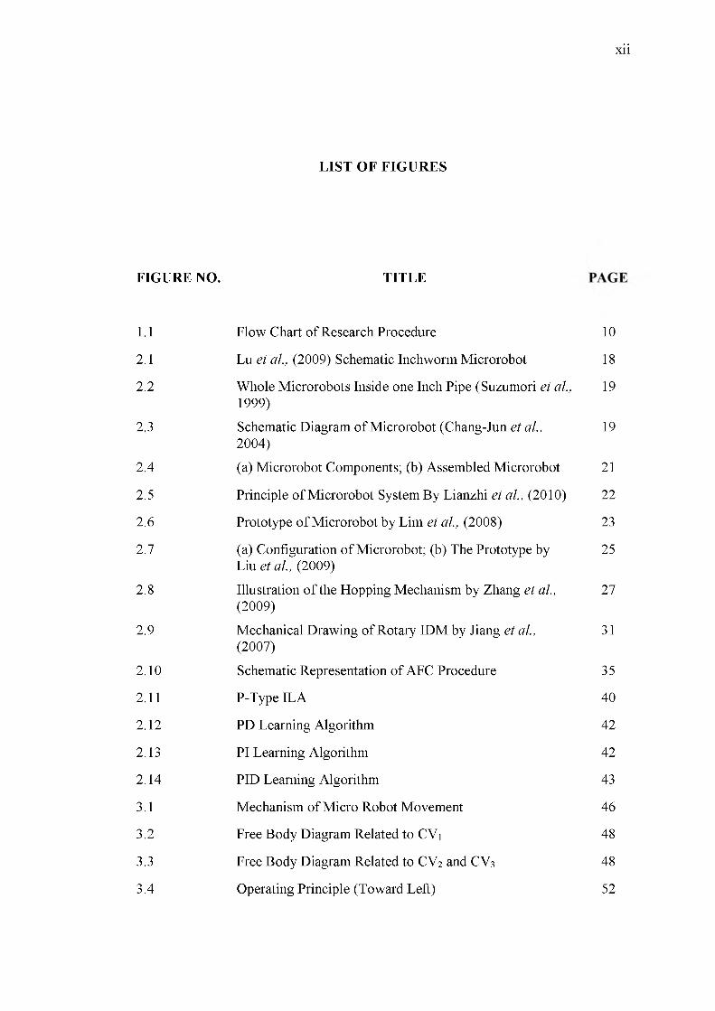
FIGURE NO. TITLE GAP
1.1 Flow Chart of Research Procedure 10
2.1 Lu et al., (2009) Schematic Inchworm Microrobot 18
2.2 Whole Microrobots Inside one Inch Pipe (Suzumori et al., 1999)
19
2.3 Schematic Diagram of Microrobot (Chang-Jun et al., 2004)
19
2.4 (a) Microrobot Components; (b) Assembled Microrobot 21
2.5 Principle o f Microrobot System By Lianzhi et al., (2010) 22
2.6 Prototype o f Microrobot by Lim et al., (2008) 23
2.7 (a) Configuration of Microrobot; (b) The Prototype by Liu et al., (2009)
25
2.8 Illustration o f the Hopping Mechanism by Zhang et al., (2009)
27
2.9 Mechanical Drawing of Rotary IDM by Jiang et al., (2007)
31
2.10 Schematic Representation of AFC Procedure 35
2.11 P-Type ILA 40
2.12 PD Learning Algorithm 42
2.13 PI Learning Algorithm 42
2.14 PID Learning Algorithm 43
3.1 Mechanism of Micro Robot Movement 46
3.2 Free Body Diagram Related to CV1 48
3.3 Free Body Diagram Related to CV2 and CV3 48
3.4 Operating Principle (Toward Left) 52
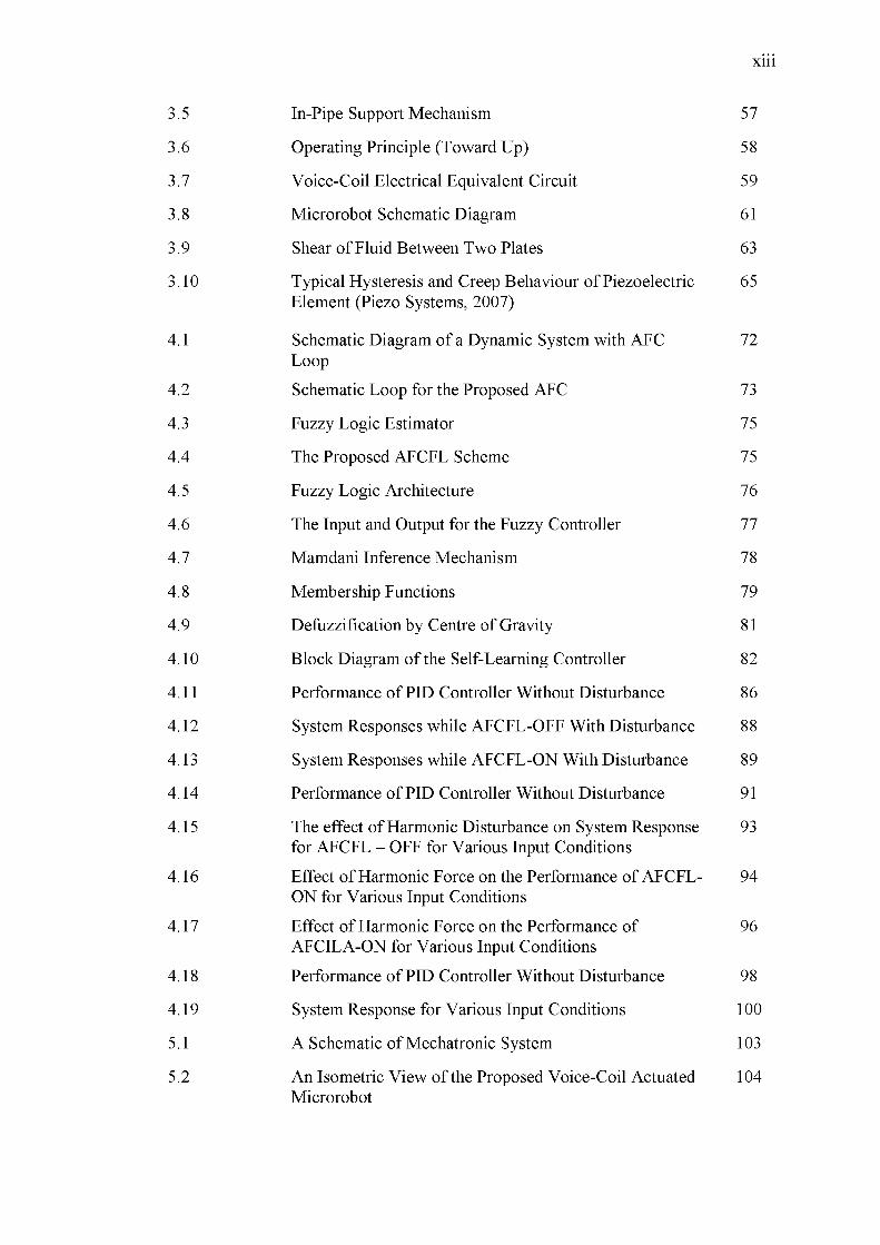
3.5 In-Pipe Support Mechanism 57
3.6 Operating Principle (Toward Up) 58
3.7 Voice-Coil Electrical Equivalent Circuit 59
3.8 Microrobot Schematic Diagram 61
3.9 Shear of Fluid Between Two Plates 63
3.10 Typical Hysteresis and Creep Behaviour of Piezoelectric 65 Element (Piezo Systems, 2007)
4.1 Schematic Diagram of a Dynamic System with AFC 72 Loop
4.2 Schematic Loop for the Proposed AFC 73
4.3 Fuzzy Logic Estimator 75
4.4 The Proposed AFCFL Scheme 75
4.5 Fuzzy Logic Architecture 76
4.6 The Input and Output for the Fuzzy Controller 77
4.7 Mamdani Inference Mechanism 78
4.8 Membership Functions 79
4.9 Defuzzification by Centre of Gravity 81
4.10 Block Diagram of the Self-Learning Controller 82
4.11 Performance o f PID Controller Without Disturbance 86
4.12 System Responses while AFCFL-OFF With Disturbance 88
4.13 System Responses while AFCFL-ON With Disturbance 89
4.14 Performance o f PID Controller Without Disturbance 91
4.15 The effect of Harmonic Disturbance on System Response 93 for AFCFL - OFF for Various Input Conditions
4.16 Effect of Harmonic Force on the Performance of AFCFL- 94 ON for Various Input Conditions
4.17 Effect of Harmonic Force on the Performance of 96 AFCILA-ON for Various Input Conditions
4.18 Performance o f PID Controller Without Disturbance 98
4.19 System Response for Various Input Conditions 100
5.1 A Schematic of Mechatronic System 103
5.2 An Isometric View of the Proposed Voice-Coil Actuated 104 Microrobot
5.3 Detailed Drawings of Parts 105
5.4 NI cDAQ-9174 and Modules 107
5.5 Detailed Drawings of the External Parts of the Voice-Coil Actuator
107
5.6 Assembled Voice-Coil Actuated with Different Materials for the Component Microrobot
109
5.7 Linear Amplifier (LCAM) Used for the Voice-Coil Actuator
110
5.8 Laser Displacement Sensor 111
5.9 Calibration Chart for Displacement Laser Sensor 112
5.10 Accelerometer Model (ADXL335) 113
5.11 Shocker for Calibration 113
5.12 Inspection Camera Model HDV610 115
5.13 Supported Laser Pointer 116
5.14 LabVIEW Control Program 117
5.15 Experimental Rig 118
5.16 Samples o f Inner Surface of Pipe 121
5.17 Payload Masses from 5 g to 45 g 122
5.18 Disturbance Placement of External Magnet Force 123
5.19 AFCILA Diagram 123
6.1 Comparison o f performance between plastic and steel masses
127
6.2 Comparison o f additional payload masses 128
6.3 Mass ratio comparison study 129
6.4 Comparison between spring stiffness (K;=133 N/m, K2=200 N/m, Ks=248 N/m)
129
6.5 Microrobot velocities in pipes with different surface finish
130
6.6 Microrobot velocities versus applied voltage 131
6.7 Microrobot mechanisms on inclined surface 132
6.8 The impact of the inclination slope on the velocity 132
6.9 Microrobot acceleration (steel masses, m2/m1=0.71, V=3 V, f=15Hz, 10 g payload applied to rear mass)
133
6.10 Microrobot acceleration (steel, m2/m1=0.71, V=3 V, f=15Hz, 15g payload applied to front mass) a) input
134
displacement function b) AFCILA controller c) uncontrolled signal
6.11 Microrobot acceleration (plastic, m2/m1=0.71, V=2 V, f 135 =10Hz, 20 g payload applied to front mass)
6.12 Microrobot acceleration (steel, m2/m1=0.71, V=2 V, f 136 =10Hz, 10 g payload applied to front mass)
6.13 Error of displacement (steel, m2/m1=0.71, V=3 V, 137 f=15Hz, 10 g payload applied to rear mass)
6.14 Mass estimation for voice-coil actuated microrobot (steel, 138 m2/m1=0.71, V=3 V, f=15Hz, 10 g payload applied torear mass)
6.15 Error of displacement (steel, m2/m1=0.71, V=2 V, f 139 =10Hz, 15 g payload applied to front mass)
6.16 Mass estimation for voice-coil actuated microrobot (steel, 139 m2/m1=0.71, V=2 V, f =10Hz, 15 g payload applied tofront mass)
6.17 Comparative results of control schemes (steel, 140 m2/m1=0.71, V=3 V, f=15Hz, 10 g payload applied tofront mass)
6.18 Displacement error (steel, m2/m1=0.71, V=3 V, f=15Hz, 141 payload 10 g to front mass)
6.19 Video scope images from inside pipe 142
ADC - Analogue to Digital Convertor
ADDA - Analogue to Digital-Digital to Analogue
AI - Artificial Intelligence
AFC - Active Force Control
AFCFL - Active Force Control with Fuzzy Logic
AFCILA - Active Force Control with Iterative Learning Algorithm
Active Force Control with Iterative Learning AlgorithmAFCILA-P -
and Proportional Control
Active Force Control with Iterative Learning AlgorithmAFCILA-PD -
and Proportional-Derivative Control
Active Force Control with Iterative Learning AlgorithmAFCILA-PI -
and Proportional-Integral Control
Active Force Control with Iterative Learning AlgorithmAFCILA-PID
and Proportional- Integral-Derivative Control
BEMF - Back Electromotive Force
CV - Control Volume
DAC - Digital to Analogue Convertor
DAQ - Data Acquisition Card
DAS - Data Acquisition System
DC - Direct Current
DOF - Degrees of Freedom
FL - Fuzzy Logic
FLC - Fuzzy Logic Controller

FLE - Fuzzy Logic Estimator
FLT - Fuzzy Logic Toolbox
FS - Full Scale
GA - Genetic Algorithm
IAE - Integrated Absolute Error
IDM - Impact Drive Mechanism
IEPE - Integrated Electronic Piezoelectric
IL - Iterative Learning
ILA - Iterative Learning Algorithm
IPMC - Ionic polymer metal composite
ISE - Integrated Square Error
ITAE - Integrated of Time multiple Absolute Error
ITSE - Integrated of Time multiple Square Error
LCAM - Linear Current Amplifier Module
LS - Least Square
MF - Membership Function
MISO - Multi Input Single Output
NI - National Instruments
NN - Neural Network
P - Proportional
PC - Personal Computer
PD - Proportional Derivative
PI - Proportional Integral
PID - Proportional, Integral, And Derivative
PSO - Particle Swarm Optimization
SIDM - Smooth Impact Drive Mechanism

SMA
TULA
Shape Memory Alloy
Tiny Ultrasonic Linear Actuator

A
aact
aref
C , C2
cP
d
e
e
ek
E
F
Fa
Fdd
F
Ft
d
f
FN
Fp
F v c a
g
G(s)
Ga (s)
Gc
Gs
I
Kh K , K
Kf
Kr
Cross area of pipe
Actual acceleration
Reference acceleration
Pneumatic capacitances
Damping coefficients of the piezoelectric actuator
Decay coefficient
Error
Rate of change of error
Error signal for ILA
External supply
Applied force
Actuator force
Disturbing force
Estimated disturbance
Frictional force
Total normal force acting on the sliding surface
Piezoelectric force
Voice-coil actuator force
Acceleration of gravity=9.81 m/s2
Dynamic system transfer function
Actuator transfer function
Transfer function o f controller
Transfer function o f sensor
Applied current
Spring stiffness
Back electromotive force constant
Critical gain
Kd - Derivative gain
KF - Force sensitivity
KI - Integral gain
k p - Stiffness coefficient of the piezoelectric actuator
KP - Proportional gain
k(t) - Number of iteration
L - Inductance of the coil
m - Mass
m - Mass rate
m i - Mass of the main body
m 2 - Mass of the small body
mact - Actual mass
m yCA - Mass of voice-coil actuator
N - Perpendicular force
Pi - Input pressure
P2 - Output pressure
Q - Disturbances
R - Bladder constant
T - Temperature
Tc - Oscillation period
u - Fluid velocity
uk - Input signal for ILA
uk+i - New input signal for ILA
^ - Friction coefficient
- Static frictional coefficients
- Kinetic frictional coefficients
v - Velocity of the cylinder
V - Applied voltage
x i - Displacement of the main body
x 2 - Displacement of the small body
x act - Actual displacement
xactuator - Displacement of actuator
x d - Desired displacement

x ref - Reference displacement
X yCA - Displacement of voice-coil actuator
x p - Reference velocity
y - Desired output for ILA
yk - Output signal for ILA
a - Acceleration
W - Integral learning parameter
<P - Proportional learning parameter
r - Derivative learning parameter
p - Density
t - Shear stress
■d - Dynamic viscosity

LIST OF APPENDICES
APPENDIX TITLE PAGE
A Voice-coil Actuator Linear Amplifier Specification 157
B Experimental Procedure and Results 162
C List of Publications 174

IN TRO D U CTIO N
1.1. Research Background
Nowadays, microrobots are widely used in a number of engineering
applications since robots of this type may be able to operate in unstructured
environments thanks to their enhanced adaptability to operate effectively, even under
hostile conditions such as radioactivity, electromagnetic field and high temperature
gradients. For industrial applications, microrobots and micromechanisms have found
more applications like equipping with appropriate instrument or micro tools which
make them more beneficial. On the other hand, the application of interest is the
operation of microrobot in unreachable or hazardous pipes that can perform a
number of tasks such as in-pipe inspection, fault diagnostics, condition monitoring
and obstacle removal. Detection or maintenance inside pipes is a very common
application for in-pipe microrobots. This type of application is often related to
difficulties such as unreachability (size restriction) or hazardous environments
(poisonous gas). The establishment of microrobots for in-pipe applications is based
on navigation, maintenance, obstacle removal, or fault detection abilities. Inside
pipes there are also different constraints that the mechanism should adapt to like
different pipe diameter or different inner surface.
1.2. Problem Statements
In this decade, microrobots are widely used in a number of engineering
applications such as high-precision manipulation system, intelligent micro
transportation system, support surgical operation, and others. One of the major
applications of these types of robots is in-pipe application, in which microrobots are
able to operate in unstructured environments because of their enhanced adaptability
to operate effectively, even under hostile conditions such as radioactivity,
electromagnetic field and high temperature gradients. Mechatronic development of
in-pipe application microrobot systems embedded with intelligent active force
control strategy is presented and investigated in this research.
The proposed microrobots are driven by pneumatic, piezoelectric and voice-
coil actuators which are modelled and simulated with AFC-based control strategy.
The intelligent active force control strategy is applied to the proposed microrobot
systems and the performance o f the controller in rejection o f disturbance is
investigated. Based on the advantages and benefits of the proposed actuators, voice-
coil actuated microrobot is selected for experimental study. An experimental rig was
set up including the integration of the related sensors, actuator, mechanical parts and
digital controller via a hardware-in-the-loop simulation configuration. Outcomes of
the study provide a strong foundation for furthering the design of specific in-pipe
microrobot applications such as visual inspection of the inner surface of pipes, fault-
diagnostics, surface machining, obstacle removal and other related tasks. Finally, a
comparative study among the proposed intelligent control schemes and some design
features (spring compression, mass material, inner pipe surface, inclined surface and
etc) was carried out.
1.3. Research Objectives
This research focuses on the mechatronic design and development of a novel
intelligent AFC scheme for the proposed in-pipe application microrobot mechanisms.
Hence, three main objectives of thesis are as follows:
❖ To present three different microrobot mechanisms driven by pneumatic,
piezoelectric, and voice-coil actuators
❖ To model, simulate, and control the proposed system using intelligent
AFC method
❖ To validate the overall proposed system through experimentation and
evaluation performed on a developed physical test for voice-coil actuated
microrobot
To achieve these objectives, the following sub-objectives are considered:
> To derive and develop the mathematical model o f the microrobot systems to
study the kinematic and dynamic behaviour of the system
> To implement a robust and effective feedback control scheme for the
proposed microrobot systems through a comprehensive simulation study
> To reduce the effect of disturbance through the intelligent AFC method
(AFCILA and AFCFL)
> To design and develop an experimental rig employing mechatronic approach
for voice-coil actuated microrobot
> To evaluate the performance of the controller through simulation and
experimental study for voice-coil microrobot
1.4. Scope of Research
The scope of this research comprises the following:
> Propose three microrobot mechanisms for in-pipe application driven by
pneumatic, piezoelectric, and voice-coil actuators
> Derive the kinematic and dynamic equations of microrobot mechanisms
based on the type o f mechanism, actuator, and movement.
> Design suitable feedback controllers based on the PID and AFC strategies for
simulation study
> Apply intelligent techniques (FL and ILA) to AFC strategy for robust
movement for the time that the system is under disturbance
> Carry out a comparative study of the proposed control schemes
> Employ a Voice-coil actuated microrobot mechanism for the experimental rig
> Perform experimental validation of the intelligent AFC algorithm on the
developed voice-coil actuated microrobot
> Investigate the performance of the control systems under different case
studies and input excitations
> Equip the microrobot with a laser pointer for specified application and a
wireless high definition video scope inspection camera
> Consider the effects of different conditions (friction, disturbance, pipe
surface, microrobot material, and etc) on microrobot movement
1.5. Research Significance and C ontribution
This research focuses on the mechatronic design of a new control system to
control movement effectively and suppress unwanted disturbances of in-pipe
application microrobots driven by pneumatic, piezoelectric and voice-coil actuators.
Voice-coil actuated microrobot is selected for mechatronic approach and there is no
background with voice-coil actuators for this kind of motion and application. By
assuming some conditions inside the pipe, the derived kinematic and dynamic
equations are unique. Intelligent AFC as a robust strategy was shown to be a
powerful disturbance rejecter is applied as main control scheme o f the system.
External force as disturbance effect is applied to the microrobot and effectiveness of
intelligent AFC to perform robust movement is examined. There is no published
research in which AFCILA or AFCFL is applied to this type of in-pipe application
microrobot. This research attempts to present an in-depth investigation of intelligent
AFC controller incorporated to voice-coil actuated microrobot and show how the
controller rejects the unwanted disturbances effectively and controls the movement
of robot precisely by experimental and simulation studies.
A brief outline of the main contributions of this research is given in this
subsection as follows:
• A comprehensive kinematic/dynamic model that justifies the dynamic
characteristics of microrobot mechanisms which are driven by pneumatic,
piezoelectric, and voice-coil actuators
• A novel in-pipe application microrobot driven by voice-coil actuator
• A novel AFC algorithm to control system behaviour in order to reject
unwanted disturbance while moving inside the pipe
• Intelligent algorithms applied to the main controller of system (AFC) to
find the parameters of the controller by programming the related codes
inside LabVIEW software
1.6. Research Methodology
The project is divided into five main stages i.e.; literature review, modeling
and simulation, design and development of the experimental rig, experimentation and
performance evaluation, and analysis. Mechatronic approach involving the synergy
of mechanical, electrical/electronic and computer control would be the main feature
of the research methodology. More detailed description of the research methodology
is as follows:
1.6.1 L iterature Review
In-pipe application microrobot mechanisms and their application, available
actuators and mechanisms are first reviewed based on previous studies. PID and AFC
controllers are also introduced and reviewed in the second section. Finally, intelligent
algorithms like FL and ILA which are used to determine specifications o f controllers
intelligently are reviewed.
1.6.2 Modelling and Simulation
Prior to the performance evaluation of the proposed model of the system, the
modelling and simulation phase include the mathematical equations, representing the
system’s dynamics and kinematics is presented. The modelling will take into account
realistic and valid assumptions related to the physical systems. Three suitable and
practical microrobot mechanisms driven by pneumatic, piezoelectric and voice-coil
actuators are introduced based on real physical system. A number of intelligent
methods such as Fuzzy Logic (FL) and Iterative Learning Algorithm (ILA) will be
studied and later implemented with the AFC strategy to control the system robustly.
Simulation works shall include the evaluation of the system’s performance and
robustness against the disturbance. Differences in the design parameters,
environmental situations, simulation, and learning algorithms shall also be taken into
account. Comparative study between the control strategies shall also be done to
provide a useful platform in determining the best control method. The simulation
works serve as a basis for designing and developing the experimental rig in later
stages. MATLAB and Simulink software’s shall be the main tool for the simulation
study.
1.6.3 Design and Development of Experim ental Rig
The design and development of the experimental rig is based on
Mechatronics approach. In this approach, all main important aspects of mechanism
and environmental situation are considered. This involves the integration o f a
number of classical engineering disciplines namely, the mechanical, electrical,
electronics and computer-based control. A complete integration o f the mentioned
disciplines is very essential to realize a mechatronic product.
• M echanical
Mechanical design initially involves the conceptual design of in-pipe
application microrobot driven by voice-coil actuator. A number of factors and
suitable design criteria should be carefully considered in the design process. The
design process will involve the development of suitable mechanisms, dynamic
analysis o f the structure of the system, selection o f materials and others which should
all comply with the pre-determined design criterion. A finalized design for voice-coil
actuated microrobot will be subsequently chosen with the detailed production
drawings ensured for fabrication purposes. Some of the mechanical aspects of the

system such as the computation of the parameters for the actuator, mass and shape of
masses, dimensions o f the system structure or parts can be obtained and/or
manipulated from the simulation study. The design should also take into account the
ease of the fabrication of the parts to be processed.
• Electrical/Electronics
The selection of the actuator and sensors should be based on the advantages
comparison to ensure proper actuation of the system is achieved. Voice-coil actuator
is suitable to be used in the system with some powerful specifications related to other
actuators and its novelty. Voice-coil actuator should be driven by a set of suitable
power supply and related amplifier. A good knowledge and skill in electronics
assembly is highly desirable at this stage. Again, the outcome of the simulation
works help in determining for example the size (power, force, friction etc.) of the
actuators to be used.
• Computer-Based Control
The next stage is involve rigorous computer interfacing and control involving
data acquisition process through the use of analogue to digital, digital to analogue
(ADDA) card and a PC/Laptop for software control. All the sensors and actuator
shall be connected to a PC-based data acquisition system (DAS). All the important
elements are later integrated and fully tested prior to the experimentations. Matlab,
Simulink, and LabVIEW serve as the link between the mechanical, electrical, and
electronics components.
• Experim entation
When the mechatronic system prototype is ready, experimental procedures
will be drafted and testing will be done to validate the effectiveness and the
robustness o f the control strategy. An experimental rig prototype shall be designed
and developed using full mechatronic approach involving the integration mechanical
engineering, electrical, electronic and computer control elements for voice-coil
actuated microrobot. The design of the rig shall be largely based on the parameters
and results obtained from the theoretical and simulation study carried out earlier
since the main aim o f developing the rig is in fact to complement simulation
counterpart. Experimentation will be rigorously carried out to test the effectiveness
of the proposed control scheme. The tests will take into account various operating
and loading conditions like applied voltage, applied frequency, different masses, pipe
surface, etc. Finally, the outcomes o f the research are summed up.
1.6.4 Perform ance Evaluation and Analysis
The system performance will be critically evaluated and analyzed based on
the capability of the control schemes. An experimental rig is setup and tested to
validate the AFCILA scheme. A comparative study of the proposed schemes in terms
of their performance and differences shall also be presented in the research. The
research outcomes should provide the information which would be useful for future
development, improvement and expansion of the system. In addition to that,
suggestions for the further research works will also be outlined.
The flowchart presented in Figure 1.1 describes the research methodology
considered in this thesis.

Figure 1.1Flow chart of research procedure
1.7. Organization of Thesis
This thesis is organized into eight chapters. A brief outline o f the contents of the
thesis is as follows:
C hapter 1 presents an introduction to the research problem. It involves the
background and significance of the research as well as the problem statement and
contributions. The logical flow and structure of the thesis are also outlined in this
chapter.
C hapter 2 is devoted to literature study that has been carried out related to
subjects concerning this thesis. Firstly, the types and classifications o f
microrobots and their actuators are studied. Secondly, Impact Drive Mechanism
(IDM) and its application on microrobots are reviewed and discussed. Thirdly,
the applications of PID and AFC strategy are described. Finally, intelligent
techniques including ILA and FL are described and reviewed due to their
application in next chapters.
C hapter 3 focuses on introducing principle of three proposed mechanisms driven
by pneumatic, piezoelectric, and voice-coil actuators. Mathematical formulations
of proposed microrobots are done. Kinematic/dynamic relations o f microrobots
are derived to model the systems and find transfer functions.
C hapter 4 presents the application and principles of the PID and AFC methods.
FL and ILA which are employed as intelligent methods to estimate the value of
mass required in AFC loop are introduced. The optimum learning parameter as
well as appropriate stopping criteria for the mentioned ILA is proposed based on
the simulation. The microrobot mechanisms are studied when the simulated
model is excited by disturbing signals and the performance of AFCFL and
AFCILA in suppressing the unwanted disturbance is investigated. First, different
types of signals are input to system. After that, of the system after applying
disturbance is considered.

C hapter 5 focuses on mechatronic design and evaluation of the experimental rig.
An in-pipe application microrobot actuated by voice-coil is developed and
fabricated. The control action is applied to the voice-coil actuator through a data
acquisition system which has been connected to a PC equipped with LabVIEW
software. The control algorithm is coded using the LabVIEW graphical
programming. Performance of the intelligent control system is evaluated through
experimental measurements. Different case-studies are prepared by altering the
design parameters (mass material, spring stiffness, friction, etc.) which are then
compared together and their effects on the output response are studied.
C hapter 6 describes the comparative study among the proposed control schemes
presented in the previous chapters. The effectiveness and imperfections o f the
each technique is described and compared with each other.
C hapter 7 sums up the research project and the directions for the future research
works are outlined.

REFERENCES
Ackerman, J. D., Cottrell, C. M., ETHIER, C. R., ALLEN, D. G. AND SPELT, J. K. (1996).
Attachment Strength Of Zebra Mussels On Natural, Polymeric And Metallic
Materials. Journal o f EnviromentalEngineering, 122: 141-148.
Aoshima, S., Tsujimura, T., and Yabuta, T. (1993). A Miniature Mobile Robot Using Piezo
Vibration for Mobility in a Thin Tube. ASME J. Dynam. Syst., 115: 270-278.
Arena, P., Bonomo, C., Fortuna, L., Frasca, M., and Graziani, S. (2006). Design And Control
of an IPMC Wormlike Robot. IEEE Transactions on Systems, Man, And
Cybernetics—Part B: Cybernetics, 36(5).
Arimoto, S., Kawamura, S. And Miyazaki, F. (1984). Bettering Operation of Robots By
Learning, J. Robotic Syst. 1:123-140.
Arimoto, S., Kawamura, S. And Miyazaki, F. (1985). Applications O f Learning Method For
Dynamic Control O f Robot Manipulators. Proc. O f 24th Conf. On Decision And
Control. Ft. Lauderdale. 1381-1386.
Arimoto, S., Kawamura, S. And Miyazaki, F. (1986). Convergence, Stability and Robustness
of Learning Control Schemes for Robot Manipulators. Recent Trends in Robotics:
Modelling, Control and Education. Elsevier, New York, 307-316.
Babuska, R. (2002). Neuro-Fuzzy Methods for Modelling and Identification. In Abraham, A.,
Jain, L.C. And Kacprzyk, J. (Editors). Recent Advance International Paradigms And
Application. Heidelberg, Springer-Verlag, 161- 186.
Baronti, F., Lazzeri, A., Lenzi, F., Roncella, R., Saletti, R. and Saponara, S. (2009). Voice
Coil Actuators: From Model and Simulation to Automotive Application in Industrial
Electronics. IECON ’09. 35th Annual Conference o f IEEE, 1805 -1810.
Bart, S., Lober, T., Howe, R., Lang, J. and Schlecht, M. (1988). Design Considerations for
Microfabricated Electric Actuators. Sensors and Actuators. 14: 269-292.
Bertetto, M. and Ruggiu, M. (2001). In-Pipe Inch-Worm Pneumatic Flexible Robot,
IEEVASME International Conference On Advanced Intelligent Mechatronics, Italy,
1226-1331.
Bolton, W. (1998). Control Engineering; Longman Inc.

![YASER KHAMAYSEH · Mouftah, "Coexistence in Personal Wireless Networks", Ad Hoc & Sensor Wireless Networks, Vol. 26, pp. 259–285, 2015. [Autosoft15] Yaser Khamayseh, Wail Mardini](https://img.pdfslide.us/doc/110x75/5e8cc834ac1f931dff708a4d/yaser-mouftah-coexistence-in-personal-wireless-networks-ad-hoc-.jpg)