Embed Size (px)
Citation preview

1
Yanni Panagiotopoulos
Jessica Hwang
Joe Ivanov
David Marin
Radio Frequency Welding of Multi-Walled Carbon Nanotubes for Plastic Bonding
Abstract
Current plastic welding technology often involves heating up an entire piece in order to achieve a
weld. This paper discusses how time and energy may be saved due to the unique property of CNTs
as thermal dissipaters. Thus, CNTs may be placed only on the plastic parts where plastic welding
or targeted heating is required. This paper discusses the theories for this powerful heating property
of CNTs and provides discussion of how this might work in a bench scale environment.
Furthermore, this includes an explanation of how dispersion of the CNTs in appropriate solvents,
as well as other material properties, can enhance the heating rate and uniformity of the weld. We
designed a solution of MWCNTs to weld high density polyethylene (HDPE), along with the RF
system and properties. The result of the design of these solutions as well as future work is given.
Motivation
The motivation of this project comes from current processing techniques used to bond plastics.
Despite the ubiquitous number of plastics techniques; from contact to laser plastic welding, they
often share the common problem: relatively low energy efficiency and high power inputs. In order
to weld two thermoplastics, the plastic body must be heated close to its melting temperature, a
process which requires excessive amounts of heat, time, and money.1 Additionally, the weld or
interface of the bond limits the overall mechanical properties, and is often the location of eventual
failure.
An alternative approach is to utilize the energy absorption properties of carbon nanotubes to
achieve a more targeted form of heating in comparison to current technologies. The absorption of
radio/microwave waves can be converted to thermal energy through two main mechanisms:
dielectric and joule heating. Dielectric heating involves the movement of dipoles to an AC
electromagnetic field. Joule heating is caused by electron scattering and collisions from the
induced current due to the AC field.
Due to the high conductivity and energy absorption of carbon nanotubes the bulk of the heating of
a CNT-polymer system is localized in the CNTs. Consequently, by applying a nanotube mixture
to a specific area, the heating can be localized and allow manufacturers to forgo bulk heating a
plastic piece.
2
Materials Science and Engineering Aspects
For this project, we are attempting to design a carbon nanotube solution/dispersion that can be
applied to plastic pieces to locally bond it. There are several materials parameters that we must
consider for the system to be chemically compatible, and to optimize/increase efficiency.
Our main materials parameters include those of the plastic, CNTs, solvent, and RF system. The
plastic and solvent type must be chemically compatible; the solvent must not corrode, degrade, or
react with the plastic within our time scale. The CNTs must be able to be well dispersed within the
solvent, and this mixture must exhibit a high enough dielectric loss tangent (imaginary dielectric
component over the real component) and conductivity at the chosen RF frequency to
optimize/maximize dielectric and joule heating.
Furthermore, using the density, specific heat, thermal conductivity, and system geometry; this
heating rate must be able to demonstrate a ‘sharp temperature’ gradient within the solvent mixture,
melting the plastic within ~micron-mm range (targeted heating). The final bond should display
mechanical properties on par or better than the bulk plastic for the desired application (i.e. the part
must not fail at the bond itself at significantly lower stress/strain than the bulk).
Previous Work
Kanzius radio frequency (RF) cancer therapy has demonstrated the ability of single walled carbon
nanotubes (SWCNTs) to absorb and convert electromagnetic radiation in the RF range into thermal
energy under an external field. The phenomenon is attributed to the SWCNTs phonon ballistic
conduction, which allow for the unimpeded flow of particles carrying a specific energy across
large distances.2 The authors, C. Gannon et al., achieved localized heating through RF induction
of SWCNTs, and were able to treat human cancer cells in a noninvasive and selective manner.2
The study used SWCNTs functionalized with Kentera, and found that small concentrations of
Kentera SWCNTs, significantly enhanced the RF heating of the solution. At a concentration of
50mg/L, the heating provided by the SWCNTs alone was 0.9K/s.
Design Goals
The goal of this project is to predict the heating rate of a CNT solution using a variety of theories.
This heating rate should be optimized, or maximized at least within the desired frequency range
(which is dependent upon environment and government regulations), based on several materials
properties such as the CNT aspect ratio, CNT type, plastic and solvent type, and AC
frequency/field strength.
3
Upon application of the CNT solution and irradiation, the polymers should ideally melt or bond
together within a smaller range than resulting from conventional techniques. This bond will need
to exhibit better mechanical performance for the current system or compared technique, which
may mean that the bond exhibits a higher tensile or yield strength than the bulk, but it depends
upon the application. Additionally, the time it takes to sufficiently bond the plastics should be
minimized. This can be achieved by cutting off the RF source at an appropriate time. Thermally
activated adhesives represent a bonding method similar to ours, so our design could be compared
to it as an additional metric.
Technical Approach
The technical approach of the project revolves around two key goals: (1) determining if there is an
optimizable heating rate and determining that heating rate (2) targeted heating. Furthermore, the
components of our system must be physically and chemically compatible, abide by federal and
laboratory regulations regarding microwave/RF radiation, follow the project’s budget, and the
plastic weld should display appropriate mechanical strength.
The heating rate and efficiency will be designed utilizing; dielectric physics; percolation theory;
General Effective Media theories. The goal is to optimize heating rate and efficiency by
maximizing microwave energy absorption and heat generation through conduction and dielectric
losses. Dielectric mixing theories will help us estimate the overall dielectric properties of the
system based on the combination and interaction of/between the individual components. By
modeling CNTs as antennas we can determine their ideal length, and from percolation theory we
know we want the lowest possible diameter. Using the calculated properties from these theories,
the heating rate can be predicted. Material parameters of importance include dielectric constant,
dielectric loss, loss tangent, percolation parameters, CNT geometry, and CNT dispersion.
Design
First, we will determine the ideal heating of a carbon nanotube mixture using theories and
equations, provided below. For the ideal case we are assuming that all nanotubes are evenly
dispersed (no agglomeration), perfectly straight (no bending or curling), orient themselves
perfectly parallel with RF radiation, the electric field strength remains constant due to the high
penetration depth of RF/microwaves and our small volume, and all are single-walled carbon
nanotubes (SWNT). In addition, estimating the ideal heating rate will help set up a system that
could be used to predict heating of less ideal systems.
Microwave frequencies are often used in telecommunications, since these frequencies are highly
regulated to ensure there is no interference, it is important to choose a compliant frequency band.
Many countries use 2.450 (+/- 0.050) GHz for research, medical, and industrial uses.4,5 There are
4
lower compliant frequencies, but at higher frequencies there is a tendency for the induced current
due to dipole movement to become more out of phase and produce more heating.
To determine our nanotube length we will assume that the CNTs do not agglomerate, and do not
curl, bend, or deform in any way. In this context, we will assume that the nanotubes act as an
antenna and will resonate at particular frequencies based on their length. Additionally, placing an
antenna in a dielectric decreases the resonant frequency and also decreases the necessary length
for resonance.6 For reasons stated later, we will use DMF, which has a dielectric constant, or
relative permittivity, of 36.7.7 The equation for reduced wavelength, or antennae length is as
follows,
(1) 𝜆 =𝑐𝑜
𝑓√(𝜀𝑟)
From this we can obtain a wavelength, or nanotube length of 2.02 mm. Many people use lambda/4
antenna, because it saves money even though the efficiency is reduced due to it being below the
true resonant length. However, we are not considering money in the ideal case.
The next parameter to consider is CNT diameter. The smallest diameter SWCNT that can be
theoretically obtained is the metallic (4,4) ‘armchair’ nanotube at 0.542 nm, which results in an
aspect ratio of 3.72*10^6 .8
We chose the lowest possible diameter because we want a high aspect ratio to decrease the critical
volume fraction (and amount of material and money needed) at the percolation threshold. The
percolation threshold in our case is the volume or concentration of a conductive filler in a dielectric
material at which the conductivity drastically increases (often orders of magnitude) and signifies
a transition of overall properties from dielectric to conducting. This relationship generally holds
for a small concentration or volume range, after which the conductivity saturates, or rises more
slowly. The reason for this sharp conductivity increase is due to the formation of a random long
range carbon nanotube network that creates pathways for electrons to flow through the material.
The relationship between conductivity and concentration above this threshold can be modeled as
a power law equation,
(2) 𝜎 = 𝜎𝑜(𝑉 − 𝑉𝑐)𝑡
The exponent, t, is mainly dependent upon the geometry of the system, so it can be estimated from
previous research that uses similar systems. 3D systems consisting of two components, a dielectric
and a conductor, usually have an exponent around t=2.9
Additionally, it has been shown experimentally that the loss tangent is locally maximized in a
small range above the percolation threshold, which may be in part due to the large increase in
conductivity, and henceforth, joule heating or conduction losses.27 The volume fraction at which
5
percolation threshold occurs can be calculated from excluded volume theory, which considers the
fact that carbon nanotubes cannot exist in the same location at the same time and factors in
rotation/orientation in a medium.10 It is important to note that this equation has been shown to
overestimate the volume fraction because it does not consider the tunneling between CNTs. This
equation can be written as,
(3) V𝑐 = 1 − exp (−<𝑉𝑒𝑥>𝑉
<𝑉𝑒>)
where,
(4) < 𝑉𝑒 > =4
3𝜋𝑊3 + 2𝜋𝑊2𝐿 + 2𝑊𝐿2 < sin(𝛾) >𝜇
(5) 𝑉 =𝜋
4𝑊2𝐿 +
𝜋
6𝑊3
Where Vc is critical volume fraction, and sin(y) for randomly oriented nanotubes converges to
lambda/4, and 0 for strictly parallel nanotubes.10 The strictly parallel case causes the volume
threshold to become invariant with respect to nanotube dimensions; it only depends upon the
average excluded volume, <Vex>. The average excluded volume is a constant based on particle
geometry. This constant can be approximated as 1.4 for’ infinitely’ long nanotubes and 2.8 for
spheres.10 For real systems of high aspect ratio, 1.4 is accurate.10 From our nanotube length and
diameter, one obtains a critical volume fraction of 1.88*10-7 for the onset of percolation, which is
small due to the large nanotube aspect ratio. For the strictly parallel case the critical volume
fraction is 0.161 for an excluded volume of 1.4.
For the ideal system we will consider the parallel case because dielectric properties and
conductivity are greatly increased in the longitudinal direction. The longitudinal dielectric
response of an isolated carbon nanotube is determined by the following equation,
(6) 휀|| = 1 +4𝜋
Ω𝛼|| ≈ 휀𝑟
,where a|| is the polarizability per unit length, and is Omega the area of the unit cell. The unit cell
of a (4,4) nanotube was calculated from equations provided by the Maruyama-Chiashi Laboratory
at The University of Tokyo,11 and determined to be 43.1 Å2. The polarizability was calculated
using an empirical relationship determined using density-functional perturbation theory (DFPT),
and is shown as,12
(7) 𝛼|| ≈ 8.2𝑅𝑜2 + 20.5
6
Where Ro is in Angstroms and the polarizability is approximately 80.72, resulting in an e|| of 24.54.
Since our ideal system consists of completely parallel carbon nanotubes, we will assume they are
oriented in the direction of the incident microwave radiation, and e|| approximates e'r.
Now with the volume fraction, we can use dielectric mixing theories to estimate the real
permittivity of a mixture based on its individual components. There are several mixing theories,
all of which require the critical volume fractions of the materials, and their relative permittivities,
many of which also include the critical volume fraction and exponent from percolation theories.
We will be looking at a mixing theory known as General Effective Medium (GEM) theory, which
combines percolation and other approaches into one equation,12
(8) 𝑉𝑙(𝜀𝑙
1𝑠−𝜀𝑚
1𝑠 )
𝜀𝑙
1𝑠+𝐴𝜀𝑚
1𝑠
+𝑉ℎ(𝜀ℎ
1𝑡 −𝜀𝑚
1𝑡 )
𝜀ℎ
1𝑡 +𝐴𝜀𝑚
1𝑡
= 0
Where el and eh are the lower and higher dielectric constants, Vl and Vh are the lower and higher
volume fractions, and A is given as,
(9) 𝐴 =1−𝑉𝑐
𝑉𝑐
From the above equation we get A=5.211. Plugging in our other parameters we obtain an effective
relative permittivity of 34.52 for the nanotube-DMF mixture.
Now the time average heating of a dielectric material can be described as,
(10) < 𝑄 >= 𝜋𝑓휀𝑚휀𝑜𝐸2tan (𝛿)
Where f is the frequency of microwaves, e0 is the permittivity of vacuum, E is the electric field
strength, tan(delta)is the loss tangent, and Q is the power density (W/m^3). The loss tangent
represents the energy loss in a material, which is dissipated as heat. The loss tangent can be
expressed as a sum of the energy losses due to dielectric dipoles tan(delta)d, and joule heating due
to electrons tan(delta)e,12
(11) tan(𝛿) = tan(𝛿)𝑑 + tan(𝛿)𝑒 =𝜀𝑟
′′
𝜀𝑟′ +
𝜎
𝜔𝜀𝑟𝜀𝑜=
𝜀𝑟′′
𝜀𝑚+
𝜎
𝜔𝜀𝑚𝜀𝑜
The conductivity of a 1D object can be determined by the Landauer formula, where it is assumed
that G=2G0, because single-walled carbon nanotube have four electron channels due to spin and
sub-lattice degeneracy,13
(12) = (4𝑒2
ℎ) 𝑇 = 𝜎
𝐴
𝐿
7
,where e is the electron charge, h is Planck’s constant, and T is the transmission coefficient. For
the ideal case for now, we will assume there is minimal electron scattering, resulting in ballistic
conduction (T=1). This gives G= 155 S, or =1.36*1012 S/m. This number is very high, because it
assumes a perfectly straight, high aspect ratio, defect free nanotube with ballistic transport. This is
not the reality, but it will serve our purposes for now, and can easily be changed later.
For dielectric loss (e''), we could not find for isolated carbon nanotubes or carbon nanotube-DMF
mixture. However, due to the symmetry of carbon nanotubes, there is minimal or no dipole
moment, and the dielectric loss component of the heating from CNTs can be ignored. This suggests
that any dielectric heating of the CNT-DMF system is mainly due to DMF. The dielectric loss of
DMF at 2.45 GHz and room temperature is 5.9.15 The electric field strength is chosen to be 1.2
kV/m to represent a standard commercial microwave oven.16
Plugging all of these numbers into equation (10) yields a very large dissipated power density of
1.96*1018 W/m3, or 6.32*1011 W for a 25.4 mm x 25.4 mm x 0.5 mm film of nanotube-DMF
mixture. This result also confirms that for high electrical conductivity, the dielectric component
can be ignored, even if the contribution of dielectric loss was considered. The contribution of
dielectric loss of DMF for total power dissipation in this case is 5.9*10-13 %.
In order to determine the heating profile/rate over time, SolidWorks heat transfer simulation was
used. The ideal case was not used as the total heating would be so high that it would most likely
melt or vaporize the entire system ‘instantaneously’. Instead to represent a more accurate system,
we modeled the CNT solution as a CNT film with 50W of internal heat generation. At a RF power
of 600W this would indicate an 8.3% efficiency. The 50W is used to get initial simulation results
and provide a framework for further calculations, once a more accurate prediction of heating is
reached.
The model consisted of a 50.8mm x 50.8mm x 0.25mm CNT film sandwiched between two 50.8
x 50.8mm x 20mm high-density polyethylene samples (HDPE). Convective heat transfer with 20C
ambient air with a transfer coefficient of 10.45 W/m^K was placed at all outer boundaries. The
initial temperature was set to 20C everywhere. A 50W total heating was set for the entire CNT-
film volume, and a ‘thermostat’ cutoff was used to change the heating power to 0W after the outer
vertices of the film reached 120C. The purposed of this was to ensure that full contact was made
between the plastic pieces, but the sample wasn’t heated so long as unnecessarily melt excess
HDPE and contribute to bulk heating.
8
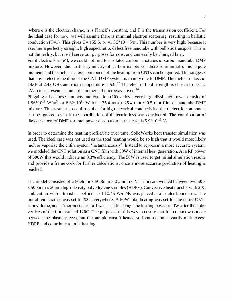
Figure 1: Results of transient heat transfer simulation in Solidworks. Maximum temperature of
124C at 75 seconds.
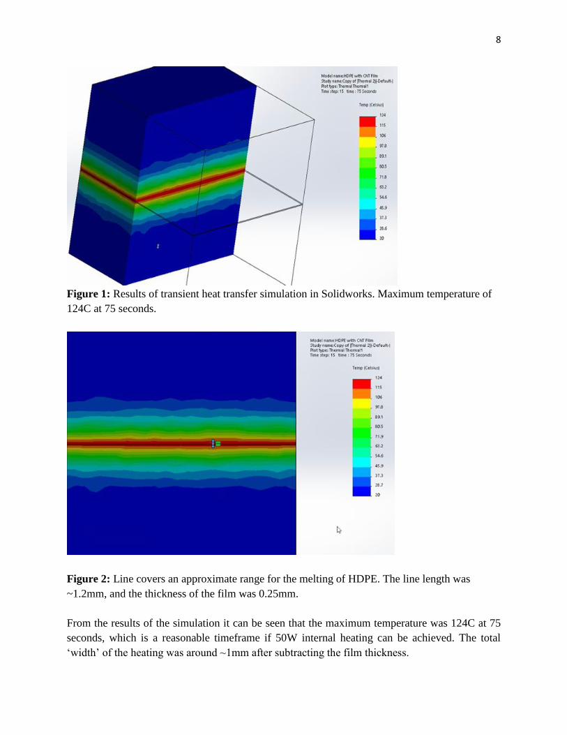
Figure 2: Line covers an approximate range for the melting of HDPE. The line length was
~1.2mm, and the thickness of the film was 0.25mm.
From the results of the simulation it can be seen that the maximum temperature was 124C at 75
seconds, which is a reasonable timeframe if 50W internal heating can be achieved. The total
‘width’ of the heating was around ~1mm after subtracting the film thickness.
9
Upon analysis of theoretical calculations for the ideal case, one can deduce that the ideal system
we portrayed is unrealistic due to the large amount of assumptions made. The combination of all
of the errors from these theories and approximations is no doubt large, however, for a more realistic
scenario these assumptions could be easily removed or tweaked. These equations provide a
framework to help calculate different properties and eventually predict the heating rate. By
empirically determining materials properties, or through other means, the number of equations and
assumptions could be reduced to arrive at a more accurate prediction of heating rate. However,
these models would still need to be compared to actual data from experiments to determine their
effectiveness and accuracy.
Empirical Studies/Derivation of Parameters
The dielectric properties of CNTs and the CNT-DMF dispersion can be found using impedance
(dielectric) spectroscopy data. Impedance spectroscopy measures the dielectric properties of a
material as a function of frequency. The data would be output in the form of a Nyquist or Bode
plot, where the impedance of the system is plotted against frequency. The dielectric constant can
then be found by fitting the Nyquist plot with an equivalent circuit equation using impedance
analyzing software such as Zview.20 An equivalent circuit is needed in order to isolate the
responses from different parts of the system. Then the fitted capacitance values of different parts
of the system can be found, which can then be used to find the dielectric constant of the material.
Unfortunately, this equipment and software was out of our budget, but this process could still be
used to obtain more a more accurate prediction of heating.
Another important parameter, both for determining heating and percolation threshold, is the
electrical conductivity. The electrical conductivity can be determined by measuring the resistivity
of the carbon nanotube solutions, and the solvents themselves. This can be accomplished by using
a standard two probe conductivity meter and a standard solvent/solution for calibration, or a four
probe method. The probes must be set up so that their distance apart is precisely known; there are
types of probes that are already designed with this in mind. The conductivity of the carbon
nanotubes can be determined by measuring the nanotube powder directly (which may be difficult
or inaccurate), or through the use of a mixing theory similar to GEM knowing at least two out of
three values. It is important to measure both the AC and DC conductivity, since our system will
use relatively high frequency radiation.
In order to determine the percolation threshold, DC conductivity measurements can be taken at
various concentrations. The measured concentrations will be determined through estimations of
the percolation threshold using volume exclusion theory, mentioned above. If necessary the
concentrations will be adjusted until a power law-type relationship is observed or a large
spike/transition occurs, which will be approximately at the critical volume fraction. Equation (2)
10
will be fitted to the graph for different Vc, and then regression analysis can be used to maximize
R2 and obtain the parameters t, and o.
Prototype
From the recommendation of Zyvex Technologies (Kentera CNT distributor), two CNT
dispersions were made with DMF and silicone oil at a concentration of 10mg/5mL and sonicated
for 30 minutes. Two 1 inch copper wires were cut and attached to the leads of an ohmmeter. The
wires were placed at opposite ends of the vial (2.25 cm apart, a depth of 15 mm) and the resistance
was measured. The resistance of DMF dispersion was measured at 250±50kOhms. The resistance
of the silicone oil was too high and thus not measureable. After 24 hours the silicone oil had almost
completely separated, and the DMF had slightly separated.
A second set of dispersions were made using the same concentration and solvents, but sonicated
for 60 minutes instead of 30 minutes. The resistance of the DMF dispersion decreased to
150±50kOhms. The resistance of the silicone oil was still too high to be measured. After 48 hrs
the silicone oil dispersion had separated, but the DMF dispersion showed no visible signs of
separation.
In order to see the effect of CNT concentration on the dispersion and resistance, two other solutions
were made at a lower concentration of 5mg/5mL and sonicated for 30 minutes. When the resistance
was measured there was too much fluctuation to reliably record a value.
Ethics and Environmental Impact
The ethical stipulations of this project include following: CNT/materials disposal, harmful/toxic
materials, RF range and its effect on humans and on manufacturing processes. It is widely known
that CNTs are an environmental hazard and potentially toxic. Therefore, the CNT solution needs
to be disposed of properly (into specific laboratory containers for the project).
Silicone oil is not considered a particularly toxic substance, but it is flammable and should be
stored and disposed of appropriately. Any simple lab gloves will do for handling it, along with
standard laboratory attire such as close-toed shoes, lab-coat, and goggles.
DMF is very hazardous and has flammable vapors. Extreme care should be taken when handling
to avoid inhaling and contact with skin, or eyes. Lab goggles and butyl rubber gloves should be
used, and DMF should never be handled outside of a fume hood. Lab procedure should be created
to minimize exposure time. Similar to silicone oil and other lab chemicals, it should be disposed
of properly. Both silicone oil and DMF should pose no environmental or health hazard inherently
if handled appropriately. While we use DMF to test lab-scale dispersion of CNTs. It is not
11
recommended to scale up for industrial processes unless proper care is taken and stricter
regulations are put in place.
The RF system must also be set-up to ensure safety. The FCC’s maximum permissible exposure
from §1.1310 is 85.2mW/cm2 for 10.56 MHz. Reaching this limit is highly unlikely, even for
higher powered radio towers, but we will use RF shielding to protect humans and laboratory
equipment.
Finally, our single most important issue involves any potential advertising of the product when
bringing it to market. Any experimental product, which may be commercialized must be
incorporated into a manufacturing process and go through the testing needed to certify its
functionality. Fraud is a serious issue, we do not want to inadvertently mislead the public or
manufacturers.
Furthermore, life cycle analysis and ethical studies of our project will help protect the consumer,
and reduce total cost through the increase of efficiency from minimizing disposed materials.
Intellectual Merit
The purpose of the project was to find a more cost and energy effective method of bonding/welding
plastics. We can show this by exhibiting targeted heating of SWCNTs via RF irradiation. This can
be demonstrated by observing the time-dependent temperature profile of the physical plastic and
CNT system. If the plastic melts or bonds occurs over an appropriately small range for a specific
application then it can be said that heating occurs locally.
Additionally, we hope to learn more about the heating mechanisms of CNTs by comparing results
to estimations from theoretical equations. The time-dependent temperature profile can be modeled
from system initial and boundary conditions, and experimentally determined materials properties
using simulation software. Which, can then be compared to the results obtained from theoretical
predictions.
Broader Impact
A phenomenon as rudimentary as plastic welding has the ability to revolutionize many industries
related to the manufacturing of plastics. CNTs thermal properties under a RF wave allows for
targeted heating of large plastic pieces for welding purposes in the aerospace, automotive, and
even 3D printing industry. Most importantly the rapid prototyping, assembly and manufacturing
of industrial parts for consumer and producer goods would be possible. Finally, it could be used
to shorten the production process and reduce the equipment used to create manufactured plastic
parts. If successful, this new form of plastic bonding will provide a novel method for the selective
heating of plastics, and/or other materials, and provide a more sustainable, environmentally
friendly, and cost effective alternative for plastics manufacturers and their subsidiaries.
12
Results & Discussion
We have selected DMF to disperse our MWNTs. DMF is recommended to disperse CNTs by
several sources, because it has low evaporation volatility, allows coupled CNT movement in an
electric field generated by the RF transmitter, and creates a uniform suspension.24,25 Low
evaporation volatility gives manufacturers a larger time window for processing, because
evaporation would increase the relative MWNT concentration, and consequently, the overall
properties. According to W., Jiaxin, et al. (2012), MWNTs reorient themselves and lineup end-end
along electric field lines.24 In fact, this was the proposed mechanism by Gannon, C., J., et al.
(2007), for their larger than predicted heating rate from the addition of SWNTs to cancer
hyperthermia agents.2 The formation of CNT ‘antennae’ of larger effective length increases RF
absorption.2 Similarly, a uniform suspension is important, because agglomeration of CNTs lowers
thermal conductivity by preventing reorientation in an electric field, and increasing phonon
scattering.26 Unfortunately, DMF reacts with many types of plastics and can cause swelling. Our
choices of plastics are mainly limited to the use of polyethylene (PE), polypropylene (PP), Nylon,
as well as some others. However, polyethylene and polypropylene are easily obtainable, and can
be used to show proof of concept and obtain initial results.
Silicone Oil is used as a standard heating fluid for different applications. The microwave
absorbance of silicone oil is enhanced by 500 times with the addition of as little as 0.04 wt% carbon
nanotubes.28 Quantitatively, silicone oil has a conductivity of ∼10^-14 S/cm. Their nanotubes were
dispersed in the silicone oil through shear mixing, which indicates the importance of processing
and preparatory techniques like centrifugation and ultrasonication. Consequently, this makes
silicone oil a viable candidate for targeted heating of MWNT in situ.28
Deionized water will be used as our standard independent variable and is expected to have the
lowest heating rate based on its ineffectiveness in dispersing carbon nanotubes. The polar nature
and relatively low steric hindrance of water simply causes the MWNT to agglomerate. However,
this makes it well suited for determining the relative effective heating rates of DMF versus silicone
oil for the experimental design.
High density polyethylene was chosen due to its higher melting (~120C-130C) point and
density/weight. This will allow us to determine the relative effectiveness of DMF and silicone oil
on heating and adhesion of the polyethylene. In comparison, to low density polyethylene, can be
melted at (105C-115C), which may be too quickly to compare effectiveness of solvents.
Kentera (poly(aryleneethynylene)s (PPE)) coatings allow for the non-covalent functionalization
of CNTs; advantageously, the CNTs can then be functionalized without altering their intrinsic
properties. Furthermore, the Kentera backbone selectively interacts with the CNTs via pi-stacking.
13
This is a non-wrapping molecular approach to creating CNT surfaces that increase their solubility.
Further, it enables the introduction of various neutral/ionic functional groups onto CNT surfaces.
These interaction can then be further enhanced using thermal carrier fluids such as silicon oil to
allow for a greater dispersion of CNTs and a faster heating rate.10
Discussion of Prototype Results
It was expected that DMF would produce better dispersion than Silicone Oil (SO) because of
previous research, but we did not expect SO to be completely unreadable. This could be due to
having too high of a concentration of CNTs, which could cause higher amounts of agglomeration
and contact resistance between CNTs. This is also supported by the visible clumping of material
on the sides of the vials (for both DMF and SO), which also seems to qualitatively indicate that
the CNT concentration should be reduced, albeit SO much more.
Doubling the sonication time did help for DMF, but still not for SO. It’s probable that no amount
of sonication or centrifugation can make up for the fact that there may be too high of a
concentration of CNTs.
Doubling the sonication time to 60 minutes resulted in SO staying longer in solution, and DMF
not visibly separating after ~48 hours. Halving the concentration at 30 minutes sonication resulted
in highly variable conductivity measurements, which may have been due to the contact resistance
of the leads, or because there were not enough CNTs to adequately form a conductive network.
However, it is more likely that all solutions need to be filtered of residual graphite, or carbonaceous
particles, and solutions need to be more carefully dispersed.
Conclusions
During the course of our project, we aimed to create an RF system as well as a CNT solution with
the goal of locally heating plastics. We had the chance to test a couple CNT solutions of DMF and
SO. Although our data is limited, from initial glance it seemed that DMF was much better at
dispersing CNTs, and as a result, stayed much longer in solution and had readable resistance values
(although quite variable at times). Doubling the sonication time seemed to improve both solutions,
although SO still could not be measured. It is likely that filtering the solutions of residual graphite,
or carbonaceous particles, and more carefully dispersing them would have better results.
From our theoretical equations we have established a framework that can be used to predict heating
of carbon nanotube systems based on dielectric and joule heating. Although the heating was
calculated for a very ideal scenario, these equations can easily be modified based on the
assumptions used. Furthermore, if more materials properties are known, many of the equations can
be removed to simplify the calculations and improve the accuracy. The simulation allows us to
14
examine the temperature, time, and bond thickness that could be achieved given the materials
properties of the system and the calculated heating rate.
Future Work
We intend to assemble the RF system based on a short wave diathermy machine which models the
Kanzius’s machines design. The design should be based on the original model using the standard
13.56MHz signal applied across two metal electrodes at 600W. The following areas of research
accompany our previous work regarding the CNTs: (1) to determine how to keep CNTs in solution
with flocculants/additives over long period of time and (2) to vary sonication time and reduce
centrifugation time to increase dispersion and rate of retention in suspension, and (3) to create a
deionized water standard solution to compare the difference thermal power dissipated due to the
CNTs. Given, these two part of the project, we could then move onto other forms of testing
regarding the heating rate as well as the tensile properties of the weld; this could be accomplished
with IR camera thermal imaging and mechanical tensile testing, respectively.
Acknowledgements
We would like to thank the following individuals for their help and contributions throughout our
project:
Mr David Prestel: For advice on the goals and RF system for our project
Corey Koval: For his help with the initial design of the RF system
Dr. Christou: For his advice on building an RF system for our project
Dr. John Cumings: For comprehensive help on the CNTs, conductivity testing, and laboratory
access.
Dr. Phaneuf: For his advice and input on the project as it progressed, and for guiding Capstone.
References
1. Grewell, D., Benatar, A., (2007). Welding of Plastics: Fundamentals and New
Developments. International Polymer Processing
15
2. Gannon, C., J., et al. (August 2007). Carbon Nanotube-enhanced Thermal Destruction of
Cancer Cells in a Noninvasive Radiofrequency Field. Cancer, 110(12), 2654-2665.
doi:10.1002/cncr.23155
3. Zyvex Nanotube Technology. (2015). ZNT-C [Technical Data Sheet]. Retrieved from
http://static1.squarespace.com/static/51b61725e4b056f3a70da3c3/t/54b04b32e4b0c24fcf6e8c25/
1420839730393/ZNT-C-1-9-15-Final.pdf (April 11, 2016).
4. Menendez, J.A., et al. (2010). Microwave Heating Processes Involving Carbon Materials.
Fuel Processing Technology, 91(1), 1-8.
5. Meredith, R. (1998). Engineers’ Handbook of Industrial Microwave Heating. The
Institution of Electrical Engineers. London, UK: The Institution of Engineering and Technology.
6. Altshuler, E.E., et al. (2007). A Review of an Electrically Small Antenna Immersed in a
Dielectric. Bedford, MA: Air Force Research Laboratory, Electromagnetics Technology
Division.
7. Dielectric Constants of Common Solvents. University of Washington Department of
Chemistry. Retrived from:
http://depts.washington.edu/eooptic/linkfiles/dielectric_chart%5B1%5D.pdf
8. Hedman, D., et al. (2015). On the Stability and Abundance of Single Walled Carbon
Nanotubes. Nature Scientific Reports.
9. Shao, W.Z., et al. (2008). Conductivity Critical Exponents Lower than the Universal
Value in Continuum Percolation Systems. Journal of Physics: Condensed Matter, 20(39), 1-5.
10. Balberg, I., et al. (1984). Excluded Volume and its Relation to the Onset of Percolation.
Physical Review B, 30(7), 1-11.
11. Maruyama, S. (2002). Chirality and Symmetry of Nanotube. Tokyo, Japan: University of
Tokyo, Department of Mechanical Engineering. Retrieved from: www.photon.t.u-
tokyo.ac.jp/~maruyama/kataura/chirality.html.
12. Wu, Y., et al. (2003). Evaluation of Mixing Rules for Dielectric Constants of Composite
Dielectrics by MC-FEM Calculation on 3D Cubic Lattice. Journal of Electroceramics, 11, 227-
239.
13. Balanis, C.A. (1989). Advanced Engineering Electromagnetics. Canada: John Wiley &
Sons, Inc.
14. McEuen, P.L., and Park, J. (2004). Electron Transport in Single-Walled Carbon
Nanotubes. MRS Bulletin, 272-275.
15. Warlock Engineering. (2004). Dielectric ‘Loss Factor’ (e’’) Measurement Over RF
Frequencies Between 0.1 - 40.0 GHz for Common Organic Solvents. URL:
www.warlock.com.au/dielectriclossOrgsolvents.pdf
16. Decat., G., and Tichelen, P. (1995). Electric and Magnetic Fields of Domestic Microwave
Ovens Quantified Under Different Conditions. Journal of Microwave Power and
Electromagnetic Energy, 30(2), 102-108.
17. Jamesina, S., and Taflove, A. (2015). Plane Wave Propagation. (Location: School,
Department). Retrieved from URL: www.ece.utah.edu/~simpson. (15 March, 2016).
16
18. Christensen, K. (2002). Percolation Theory. London, UK: Imperial College London,
Blackett Laboratory.
19. M.Y., Koledintseva, R.E., DuBroff, and R.W., Schwartz. (2006). A Maxwell Garnet
Model for Dielectric Mixtures Containing Conducting Particles at Optical Frequencies. Progess
In Electromagnetics Research, 63, 223-242.
20. Reece, C. (2005). An Introduction to Electrochemical Impedance Spectroscopy. Jefferson
Lab. Retrieved from URL: https://www.jlab.org/conferences/tfsrf/Thursday/Th2_1-
EIS%20intro%20Reece.pdf.
21. Z. Wang, et al. (2012). Effect of High Aspect Ratio Filler on Dielectric Properties of
Polymer Composites: A Study on Barium Titanate Fibers and Graphene Platelets. IEEE
Transactions on Dielectrics and Electrical Insulation, 19, 960-967.
22. R., Abraham, R., Guo, and A.S., Bhalla. (2004). Modeling Premittivity and Tangent Loss
in Dielectric Materials Using Finite Element Method and Monte Carlo Simulation.
Ferroelectrics, 315, 1-15.
23. Wang, C. Y., Chen, T. H., Chang, S. C., Cheng, S. Y., & Chin, T. S. (2007). Strong
Carbon‐Nanotube–Polymer Bonding by Microwave Irradiation. Advanced Functional Materials,
17(12), 1979-1983.
24. W., Jiaxin, et al. (January 2012). Bonding horizontal aligned carbon nanotubes with a
high-frequency electromagnetic induction heating method. Journal of Nanoengineering and
nanosystems, 1-5.
25. Freiman, S., et al. (March 2008). NIST Recommended Practice Guide: Measurements
Issues in Single Wall Carbon Nanotubes. NIST.
26. Huang, Y., and Terentjev, E., M. (January 2012). Dispersion of Carbon Nanotubes:
Mixing, Sonication, Stabilization, and Composite Properties. Polymers, 4, 275-295.
27. He, F., et al. (2009). High Dielectric Permittivity and Low Percolation Threshold in
Nanocomposites Based on Poly(vinylidene fluoride) and Exfoliated Graphite Nanoplates.
Advanced Materials, 21, 710-715.
28. Paton, K.R., and Windle, A.H. (2008). Efficient Microwave Energy Absorption by
Carbon Nanotubes. Carbon, 46(14), 1935-1941.


![Book - Yanni - The Best of Yanni (Piano Solos)[1]](https://img.pdfslide.us/doc/110x75/5571f23649795947648c5611/book-yanni-the-best-of-yanni-piano-solos1.jpg)