Embed Size (px)
Citation preview
- 1 -
Owner’s Manual Model: Yamaha Viking
Caution: Before using this product, read this manual and follow all safety instructions.
Yamaha Viking Vision Cab kit*
Safety Instructions
Kit Contents
Tool Requirement
Assembly Instructions
Additional Notes
* DefenderCab ™ and accessories are in no way affiliated with Yamaha Motor Corp. Any use of these or the Viking name(s) is only to identify their utility vehicle as it pertains to our accessories. Yamaha and Viking are registered trademarks of Yamaha Motor Corp.
2
Warning: Failure to heed all safety and operating instructions and / or warnings regarding use of this product can result in serious bodily injury.
SAFETY INSTRUCTIONS
Read entire assembly instructions prior to commencing work. Install all parts indicated in assembly instructions. Failure to fully assemble product before use could result in personal injury. Assembly of product requires use of hand and/or power tools. If you are not experienced in using these types of tools, have product dealer do the installation for you. Some parts contain sharp edges; wear protective gloves if necessary.
Dress for safety. Do not wear loose clothing, neckties or jewelry if using power tools to assemble this product. Always keep your assembly area clean, uncluttered and well lit. Keep visitors and children a safe distance away from the assembly area. Visitors should wear the same safety equipment described above. NEVER OPERATE YOUR UTV WITH THE CAB DOORS OPEN. FAILURE TO PROPERLY LATCH THE DOORS PRIOR TO MOVING THE VEHICLE COULD
RESULT IN SERIOUS INJURY. Additional Safety Note(s): Some optional installation steps require that some fasteners pertaining to safety devices be temporarily removed. By choosing to perform these steps, you are doing so at your own risk and accept full responsibility should these safety devices fail due to your tampering with them. Please consider the full extent of possible repercussions when choosing to remove any safety device such as nets or safety belts.
3
Cab Enclosure Kit Contents Your DefenderCab™ kit should contain the parts listed below. Separate all parts from packing materials. Do not discard packing material until assembly is complete. Item quantities are listed in parenthesis below. Note: Items listed below may or may not be included based on selected options. Panels, Doors and Brackets
(1) Windshield Panel
(1) Back Panel
(1ea) Driver & Passenger Door Assy
(1ea) Driver and Passenger Striker Mounts
(1ea) Driver and Passenger Door Hinge Bracket Assy
(2) Back Panel side brackets
Hardware
(2) Striker Bolts
(1) Roll, Low Density Foam
(4) Pipe Clamp, 2” OD
(1) Hardware Bag* *NOTE: Hardware bag contains spare items. Some items may or may not be used for this application.
Note: The full cab enclosure is meant to be used with factory plastic roof. If you do not have the roof on your machine it can be purchased through your local Yamaha dealer.
Tools Required for Assembly Ensure that following tools are available before you begin the assembly of your Defender Cab™ Enclosure Kit. *** Assembly may require assistance***
NOTE: Stainless Steel hardware WILL gall (seize) without use of anti-seize compound
Phillips & Flat screwdrivers
1/8” and 5/32 Allen Key
4mm Hex tamper-resistant insert bit
Metric wrench and socket sets
Vice-grip pliers
Electric drill
1/4” drill bit
Utility knife
Utility clamps (Suggested)
Rubber Mallet (Suggested)
Anti-Seize Compound or Lubricant
4
Fig.2B
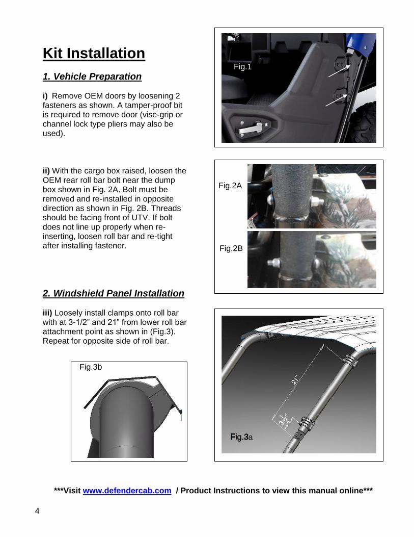
Kit Installation
1. Vehicle Preparation i) Remove OEM doors by loosening 2 fasteners as shown. A tamper-proof bit is required to remove door (vise-grip or channel lock type pliers may also be used). ii) With the cargo box raised, loosen the OEM rear roll bar bolt near the dump box shown in Fig. 2A. Bolt must be removed and re-installed in opposite direction as shown in Fig. 2B. Threads should be facing front of UTV. If bolt does not line up properly when re-inserting, loosen roll bar and re-tight after installing fastener.
2. Windshield Panel Installation iii) Loosely install clamps onto roll bar with at 3-1/2” and 21” from lower roll bar attachment point as shown in (Fig.3). Repeat for opposite side of roll bar.
***Visit www.defendercab.com / Product Instructions to view this manual online***
Fig.2A
Fig.1
Fig.3b
Fig.3a
5
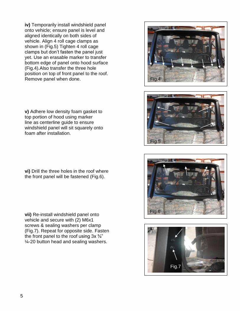
iv) Temporarily install windshield panel onto vehicle; ensure panel is level and aligned identically on both sides of vehicle. Align 4 roll cage clamps as shown in (Fig.5) Tighten 4 roll cage clamps but don’t fasten the panel just yet. Use an erasable marker to transfer bottom edge of panel onto hood surface (Fig.4).Also transfer the three hole position on top of front panel to the roof. Remove panel when done. v) Adhere low density foam gasket to top portion of hood using marker line as centerline guide to ensure windshield panel will sit squarely onto foam after installation. vi) Drill the three holes in the roof where the front panel will be fastened (Fig.6). vii) Re-install windshield panel onto vehicle and secure with (2) M6x1 screws & sealing washers per clamp (Fig.7). Repeat for opposite side. Fasten the front panel to the roof using 3x ¾” ¼-20 button head and sealing washers.
Fig.4
Fig.5
Fig.7
Fig.6
6
Fig.8-2
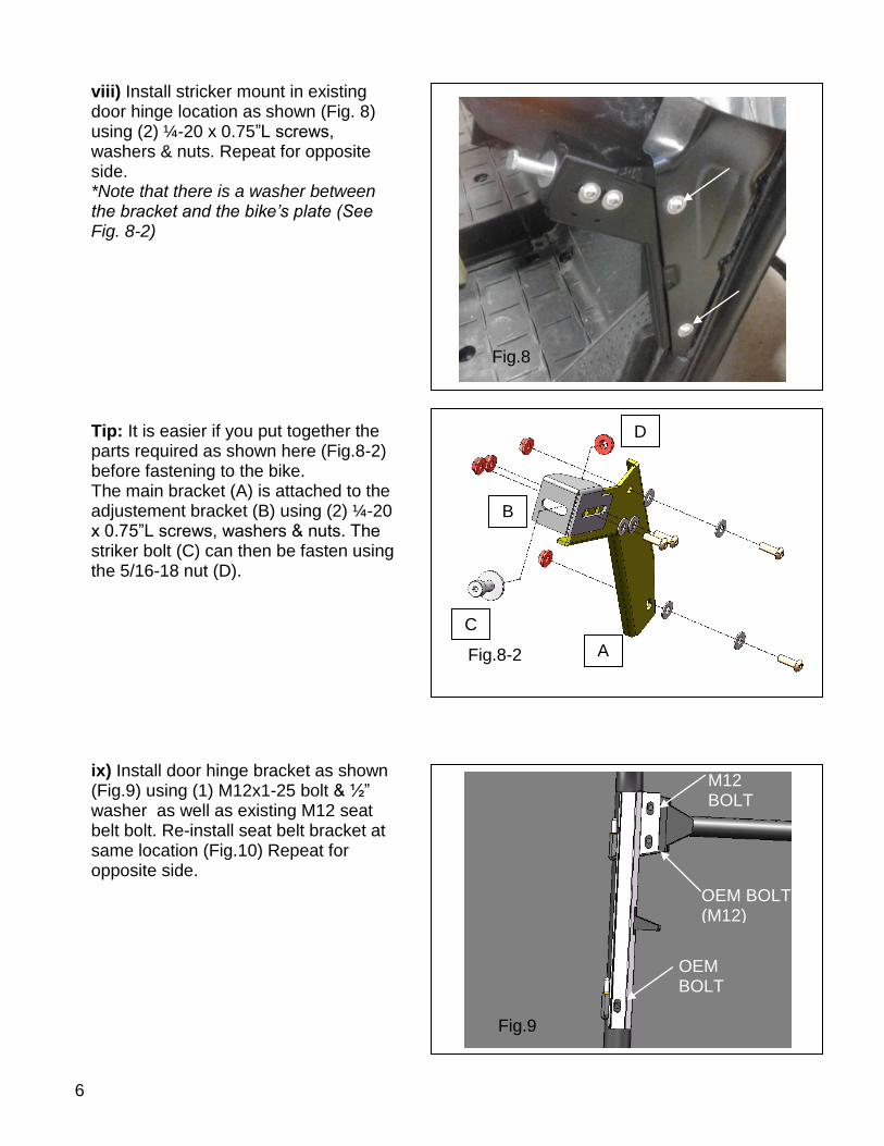
viii) Install stricker mount in existing door hinge location as shown (Fig. 8) using (2) ¼-20 x 0.75”L screws, washers & nuts. Repeat for opposite side. *Note that there is a washer between the bracket and the bike’s plate (See Fig. 8-2) Tip: It is easier if you put together the parts required as shown here (Fig.8-2) before fastening to the bike. The main bracket (A) is attached to the adjustement bracket (B) using (2) ¼-20 x 0.75”L screws, washers & nuts. The striker bolt (C) can then be fasten using the 5/16-18 nut (D). ix) Install door hinge bracket as shown (Fig.9) using (1) M12x1-25 bolt & ½” washer as well as existing M12 seat belt bolt. Re-install seat belt bracket at same location (Fig.10) Repeat for opposite side.
Fig.8
Fig.9
OEM BOLT
OEM BOLT (M12)
M12 BOLT
A
B
C
D
7
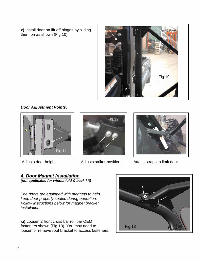
x) Install door on lift off hinges by sliding them on as shown (Fig.10). Door Adjustment Points: Adjusts door height. Adjusts striker position. Attach straps to limit door
4. Door Magnet Installation (not applicable for windshield & back kit)
The doors are equipped with magnets to help keep door properly sealed during operation. Follow instructions below for magnet bracket installation: xi) Loosen 2 front cross bar roll bar OEM fasteners shown (Fig.13). You may need to loosen or remove roof bracket to access fasteners.
Fig.12
Fig.11
Fig.10
Fig.13
8
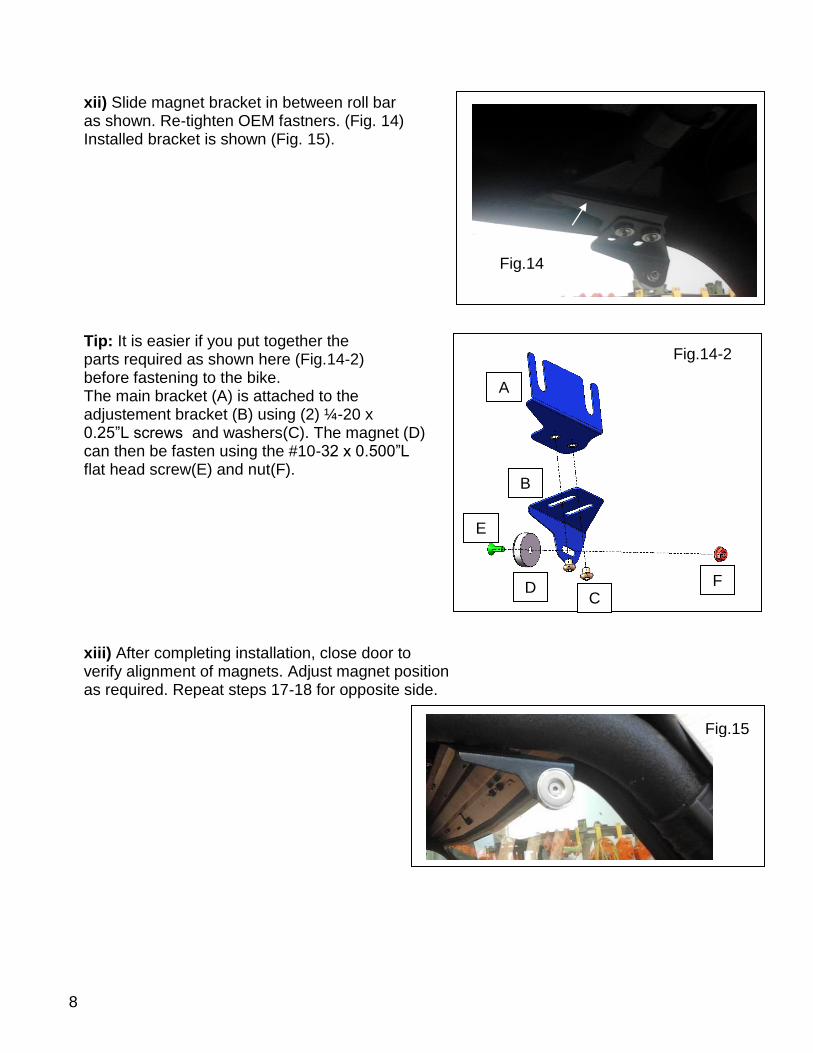
xii) Slide magnet bracket in between roll bar as shown. Re-tighten OEM fastners. (Fig. 14) Installed bracket is shown (Fig. 15). Tip: It is easier if you put together the parts required as shown here (Fig.14-2) before fastening to the bike. The main bracket (A) is attached to the adjustement bracket (B) using (2) ¼-20 x 0.25”L screws and washers(C). The magnet (D) can then be fasten using the #10-32 x 0.500”L flat head screw(E) and nut(F). xiii) After completing installation, close door to verify alignment of magnets. Adjust magnet position as required. Repeat steps 17-18 for opposite side.
Fig.15
Fig.14
Fig.14-2
F D
B
A
C
E
9
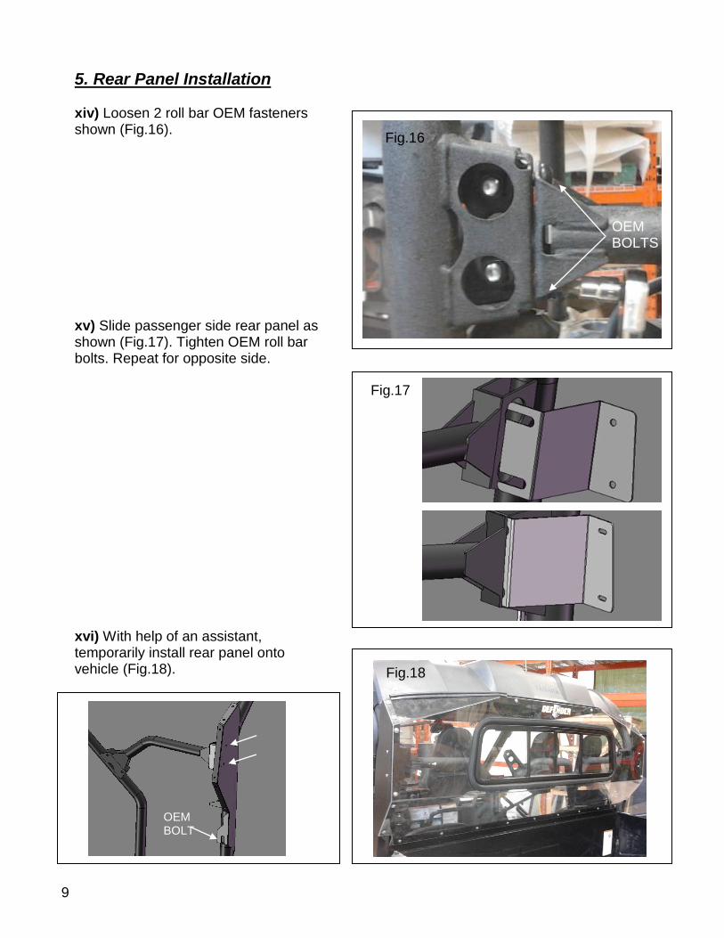
5. Rear Panel Installation xiv) Loosen 2 roll bar OEM fasteners shown (Fig.16). xv) Slide passenger side rear panel as shown (Fig.17). Tighten OEM roll bar bolts. Repeat for opposite side. xvi) With help of an assistant, temporarily install rear panel onto vehicle (Fig.18).
Fig.18
Fig.16
OEM BOLTS
Fig.17
Fig.18
OEM BOLT
10
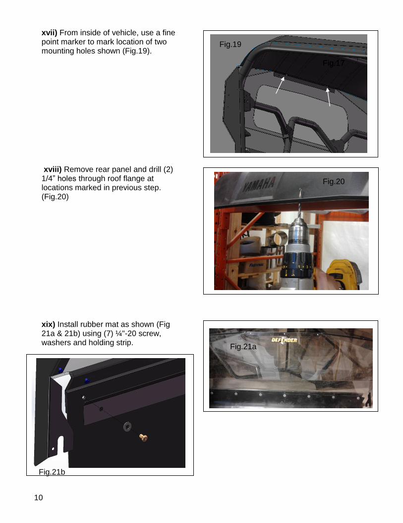
xvii) From inside of vehicle, use a fine point marker to mark location of two mounting holes shown (Fig.19). xviii) Remove rear panel and drill (2) 1/4” holes through roof flange at locations marked in previous step. (Fig.20) xix) Install rubber mat as shown (Fig 21a & 21b) using (7) ¼"-20 screw, washers and holding strip.
Fig.19
Fig.17 Fig.17
Fig.20
Fig.21a
Fig.21b
11
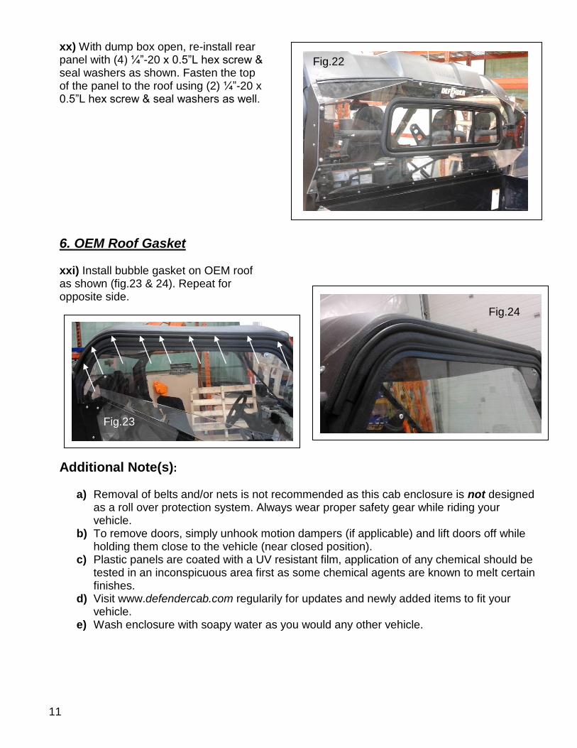
xx) With dump box open, re-install rear panel with (4) ¼”-20 x 0.5”L hex screw & seal washers as shown. Fasten the top of the panel to the roof using (2) ¼”-20 x 0.5”L hex screw & seal washers as well.
6. OEM Roof Gasket xxi) Install bubble gasket on OEM roof as shown (fig.23 & 24). Repeat for opposite side.
Additional Note(s): a) Removal of belts and/or nets is not recommended as this cab enclosure is not designed
as a roll over protection system. Always wear proper safety gear while riding your vehicle.
b) To remove doors, simply unhook motion dampers (if applicable) and lift doors off while holding them close to the vehicle (near closed position).
c) Plastic panels are coated with a UV resistant film, application of any chemical should be tested in an inconspicuous area first as some chemical agents are known to melt certain finishes.
d) Visit www.defendercab.com regularily for updates and newly added items to fit your vehicle.
e) Wash enclosure with soapy water as you would any other vehicle.
Fig.22
Fig.24
Fig.23
12
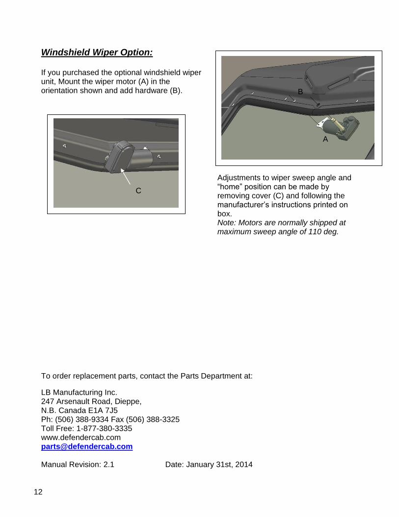
Windshield Wiper Option: If you purchased the optional windshield wiper unit, Mount the wiper motor (A) in the orientation shown and add hardware (B).
Adjustments to wiper sweep angle and “home” position can be made by removing cover (C) and following the manufacturer’s instructions printed on box. Note: Motors are normally shipped at maximum sweep angle of 110 deg.
To order replacement parts, contact the Parts Department at:
LB Manufacturing Inc. 247 Arsenault Road, Dieppe, N.B. Canada E1A 7J5 Ph: (506) 388-9334 Fax (506) 388-3325 Toll Free: 1-877-380-3335 www.defendercab.com [email protected] Manual Revision: 2.1 Date: January 31st, 2014
B
A
C