Embed Size (px)
Citation preview
Programming Manual ENGLISH E
RCX seriesYAMAHA ROBOT CONTROLLER
IM Operations882 Soude, Naka-ku, Hamamatsu, Shizuoka 435-0054.JapanURL http://www.yamaha-motor.jp/robot/index.html
YAMAHA MOTOR CO., LTD.
E76-Ver. 2.11

1
2
Introduction
Our sincere thanks for your purchase of this YAMAHA robot controller.
This manual describes robot program commands and related information for usingYAMAHA RCX series robot controllers. Be sure to read this manual carefully as well asrelated manuals and comply with their instructions for using the YAMAHA robotcontrollers safely and correctly.
For details on how to operate YAMAHA robot controllers, refer to the separate controlleruser's manual that comes with the YAMAHA robot controller.
Applicable controllers: RCX240, RCX141, RCX142, RCX40, RCX221 and RCX222
Model names as used in this manual include the following controllers.RCX240 ... Includes RCX240, RCX141, RCX142 and RCX40 (4-axis controllers)
RCX14x ... Includes RCX141, RCX142 and RCX40 (4-axis controllers excluding RCX240)*
RCX22x ... Includes RCX221 and RCX222 (2-axis controllers)
* Here, "RCX14x" does not include RCX240 and is used when there is a difference betweenthe RCX240 and other 4-axis controllers due to differences in software versions.
2
2
Safety precautions (Be sure to read before using)
Before using the YAMAHA robot controller, be sure to read this manual and related manu-als, and follow their instructions to use the robot controller safely and correctly.Warning and caution items listed in this manual relate to YAMAHA robot controllers.When this robot controller is used in a robot controller system, please take appropriatesafety measures as required by the user’s individual system.
This manual classifies safety caution items and operating points into the following levels,along with symbols for signal words “WARNING”, “CAUTION” and “NOTE”.
w WARNING"WARNING" indicates a potentially hazardous situation which, if not avoided, couldresult in death or serious injury.
c CAUTION"CAUTION" indicates a potentially hazardous situation which, if not avoided, could result inminor or moderate injury or damage to the equipment or software.
n NOTEExplains key points in the operation in a simple and clear manner.
Note that the items classified into “CAUTION” might result in serious injury dependingon the situation or environmental conditions. So always comply with CAUTION andWARNING instructions since these are essential to maintain safety.
Keep this manual carefully so that the operator can refer to it when needed. Also makesure that this manual reaches the end user.
[System design precautions]
c CAUTIONWhen the program execution stops before it is complete, the program re-executes the command thathas stopped. Keep this point in mind when re-executing the program, for example, when using anarch motion with the MOVE command, a relative movement command such as the MOVEI orDRIVEI command, or a communication command such as the SEND command.
This manual does not constitute a concession of rights or a guarantee of industrial rights. Pleaseacknowledge that we bear no liability whatsoever for conflicts with industrial rights arising from
the contents of this manual.
2010 YAMAHA MOTOR CO., LTD.
i
Contents1. The YAMAHA Robot Language ......................................................... 1
2. Characters ........................................................................................ 2
3. Program Names ................................................................................ 3
4. Identifiers.......................................................................................... 7
5. Command Statement Format ............................................................ 8
6. Constants .......................................................................................... 96.1 Character constants ...................................................................................... 96.2 Numeric constants ........................................................................................ 9
6.2.1 Integer constants .......................................................................................................... 9
6.2.2 Real constants .............................................................................................................. 9
7. Variables ......................................................................................... 107.1 Valid range of variables .............................................................................. 11
7.1.1 Valid range of dynamic variables ................................................................................ 11
7.1.2 Valid range of static variables ..................................................................................... 11
7.1.3 Valid range of dynamic array variables ....................................................................... 11
7.2 Character variables ..................................................................................... 127.3 Numeric variables ...................................................................................... 12
7.3.1 Integer variables ......................................................................................................... 12
7.3.2 Real variables ............................................................................................................. 12
7.4 Array variables ............................................................................................ 12
7.5 Clearing variables ....................................................................................... 137.5.1 Clearing dynamic variables ........................................................................................ 13
7.5.2 Clearing static variables ............................................................................................. 13
8. Other Variables ............................................................................... 14
9. Expressions and Operations ............................................................ 249.1 Arithmetic operations ................................................................................. 24
9.1.1 Arithmetic operators ................................................................................................... 24
9.1.2 Relational operators ................................................................................................... 24
9.1.3 Logic operations ......................................................................................................... 25
9.1.4 Priority of arithmetic operation ................................................................................... 25
9.1.5 Data format conversion .............................................................................................. 26
9.2 Character string operations ......................................................................... 269.2.1 Character string connection ....................................................................................... 26
9.2.2 Character string comparison ....................................................................................... 26
9.3 Point data format ........................................................................................ 279.3.1 Joint coordinate format ............................................................................................... 27
9.3.2 Cartesian coordinate format ....................................................................................... 27
9.4 DI/DO conditional expressions ................................................................... 27
10. Multiple Robot Control ................................................................... 2810.1 Overview ................................................................................................... 2810.2 Command list for each group...................................................................... 29
ii
11. Command Statements ..................................................................... 30ABSRST statement ................................................................................................. 30ACCEL statement(Acceleration setting statement for main group) .................................................... 31
ACCEL2 statement(Acceleration setting statement for sub group) ....................................................... 32ARCH statement(Arch position setting statement for main group) ................................................... 33ARCH2 statement(Arch position setting statement for sub group) ...................................................... 34
ASPEED statement(Automatic movement speed setting statement for main group) ............................. 35ASPEED2 statement(Automatic movement speed setting statement for sub group) ............................... 36AXWGHT statement(Axis tip weight setting statement for main group) ................................................. 37
AXWGHT2 statement(Axis tip weight setting statement for sub group) ................................................... 38CALL statement ..................................................................................................... 39CHGPRI statement ................................................................................................ 40
CUT statement ...................................................................................................... 41DECEL statement(Deceleration setting statement for main group) .................................................... 42DECEL2 statement(Deceleration setting statement for sub group) ...................................................... 43
DECLARE statement .............................................................................................. 44DEF FN statement ................................................................................................. 46DELAY statement .................................................................................................. 47
DIM statement(Array variable declaration statement) ................................................................... 48DO statement (Parallel output) .............................................................................. 49DRIVE statement ................................................................................................... 50
DRIVE2 statement ................................................................................................. 55DRIVEI statement .................................................................................................. 60DRIVEI2 statement ................................................................................................ 63
EXIT FOR statement .............................................................................................. 66EXIT SUB statement .............................................................................................. 67EXIT TASK statement ............................................................................................. 68
FOR statement, NEXT statement ........................................................................... 69GOSUB statement, RETURN statement ................................................................. 70GOTO statement................................................................................................... 71
HALT statement .................................................................................................... 72HAND definition statement, CHANGE statement (Main robot hand selection) ...... 73HAND2 definition statement, CHANGE2 statement (Sub robot hand selection) .... 77
HOLD statement ................................................................................................... 81IF statement .......................................................................................................... 82INPUT statement .................................................................................................. 84
LET statement (Assignment statement) ................................................................... 85LO statement (Arm lock output) ............................................................................ 87MO statement (Internal output) ............................................................................. 88
MOVE statement(Absolute position movement command) .............................................................. 89
iii
MOVE2 statement(Absolute position movement command) .............................................................. 98
MOVEI statement(Relative position movement command) ............................................................. 107MOVEI2 statement(Relative position movement command) ............................................................. 110ON ERROR GOTO statement ............................................................................. 113
ON to GOTO statement ...................................................................................... 114ON to GOSUB statement .................................................................................... 115ONLINE statement, OFFLINE statement .............................................................. 116
ORGORD statement(Return-to-origin sequence setting statement for main group) .............................. 117ORGORD2 statement(Return-to-origin sequence setting statement for sub group) ................................ 118ORIGIN statement .............................................................................................. 119
OUT statement ................................................................................................... 120OUTPOS statement(OUT position setting statement for main group) ................................................. 121OUTPOS2 statement(OUT position setting statement for sub group) ................................................... 122
PATH-related statements ..................................................................................... 123What is a PATH function? ....................................................................................................... 123
PATH statement (PATH-related statements) ............................................................................. 125
PATH END statement (PATH-related statements) ..................................................................... 129
PATH SET statement (PATH-related statements) ...................................................................... 130
PATH START statement (PATH-related statements) .................................................................. 132
PDEF statement ................................................................................................... 133PMOVE statement (Pallet movement command) .................................................. 134PMOVE2 statement (Pallet movement command) ................................................ 138
PRINT statement ................................................................................................. 142Pn (Point definition statement) ............................................................................ 143REM (Comment statement) .................................................................................. 144
RESET statement ................................................................................................. 145RESTART statement ............................................................................................. 146RESUME statement ............................................................................................. 147
RIGHTY statement, LEFTY statement ................................................................... 148RIGHTY2 statement, LEFTY2 statement ............................................................... 149Sn (Shift coordinate definition statement) ............................................................ 150
SELECT CASE statement, END SELECT statement ................................................ 151SEND statement .................................................................................................. 152SERVO statement ................................................................................................ 154
SERVO2 statement .............................................................................................. 155SET statement ..................................................................................................... 156SHARED statement ............................................................................................. 157
SHIFT statement(Shift coordinate setting statement for main robot) .............................................. 158SHIFT2 statement(Shift coordinate setting statement for sub robot) ................................................. 159SO statement (Serial output) ................................................................................ 160
SPEED statement(Speed setting statement for main group) ............................................................. 161SPEED2 statement(Speed setting statement for sub group) ............................................................... 162
iv
START statement ................................................................................................. 163
SUB statement, END SUB statement ................................................................... 164SUSPEND statement ........................................................................................... 166SWI statement ..................................................................................................... 167
TO statement ...................................................................................................... 168TOLE statement(Tolerance setting statement for main group) ....................................................... 169TOLE2 statement(Tolerance setting statement for sub group) ......................................................... 170
TORQUE statement ............................................................................................ 171TORQUE2 statement .......................................................................................... 172TRQTIME statement ............................................................................................ 173
TRQTIME2 statement .......................................................................................... 174WAIT statement .................................................................................................. 175WEIGHT statement(Tip weight parameter setting statement for main robot) ...................................... 176
WEIGHT2 statement(Tip weight parameter setting statement for sub robot) ......................................... 177WHILE statement, WEND statement ................................................................... 178Label statement ................................................................................................... 179
12. Functions ...................................................................................... 18012.1 Arithmetic functions ................................................................................. 18012.2 Character string functions ......................................................................... 19912.3 Point functions .......................................................................................... 202
13. Multi-tasking ................................................................................. 20513.1 Outline ..................................................................................................... 205
13.2 Task definition .......................................................................................... 20513.3 Task status and transition .......................................................................... 20613.4 Starting tasks ............................................................................................. 207
13.5 Task scheduling ........................................................................................ 20713.6 Condition wait in task ............................................................................... 20813.7 Suspending and restarting tasks ................................................................ 209
13.8 Deleting tasks ........................................................................................... 20913.9 Stopping tasks ........................................................................................... 21013.10 Multi-task program example ..................................................................... 211
13.11 Sharing the data ........................................................................................ 212
14. Data file description ..................................................................... 21314.1 Program file .............................................................................................. 214
14.1.1 All programs ............................................................................................................ 214
14.1.2 One program ........................................................................................................... 215
14.2 Point file ................................................................................................... 21614.2.1 All points ................................................................................................................. 216
14.2.2 One point ................................................................................................................ 217
14.3 Point comment file ................................................................................... 21814.3.1 All point comments .................................................................................................. 218
14.3.2 Individual point comment ........................................................................................ 219
14.4 Parameter file ............................................................................................ 22014.4.1 All parameters .......................................................................................................... 220
14.4.2 One parameter ......................................................................................................... 222
14.5 Shift coordinate definition file ................................................................... 22314.5.1 All shift data ............................................................................................................. 223
v
14.5.2 One shift definition .................................................................................................. 224
14.6 Hand definition file .................................................................................. 22514.6.1 All hand data ........................................................................................................... 225
14.6.2 One hand definition ................................................................................................. 226
14.7 Pallet definition file ................................................................................... 22714.7.1 All pallet definitions ................................................................................................. 227
14.7.2 One pallet definition ................................................................................................ 229
14.8 All file ...................................................................................................... 23014.8.1 All files ..................................................................................................................... 230
14.9 Program directory file ............................................................................... 23114.9.1 Entire program directory ........................................................................................... 231
14.9.2 One program ........................................................................................................... 232
14.10 Parameter directory file ............................................................................. 23314.10.1 Entire parameter directory ........................................................................................ 233
14.11 Variable file .............................................................................................. 23414.11.1 All variables ............................................................................................................. 234
14.11.2 One variable ............................................................................................................ 236
14.12 Constant file ............................................................................................. 23714.12.1 One character string ................................................................................................. 237
14.13 Array variable file ..................................................................................... 23814.13.1 All array variables .................................................................................................... 238
14.13.2 One array variable ................................................................................................... 240
14.14 DI file ....................................................................................................... 24114.14.1 All DI information .................................................................................................... 241
14.14.2 One DI port ............................................................................................................. 242
14.15 DO file ..................................................................................................... 24314.15.1 All DO information .................................................................................................. 243
14.15.2 One DO port ........................................................................................................... 244
14.16 MO file ..................................................................................................... 24514.16.1 All MO information .................................................................................................. 245
14.16.2 One MO port ........................................................................................................... 246
14.17 LO file ...................................................................................................... 24714.17.1 All LO information ................................................................................................... 247
14.17.2 One LO port ............................................................................................................ 248
14.18 TO file ...................................................................................................... 24914.18.1 All TO information ................................................................................................... 249
14.18.2 One TO port ............................................................................................................. 250
14.19 SI file ........................................................................................................ 25114.19.1 All SI information ..................................................................................................... 251
14.19.2 One SI port .............................................................................................................. 252
14.20 SO file ...................................................................................................... 25314.20.1 All SO information ................................................................................................... 253
14.20.2 One SO port ............................................................................................................ 254
14.21 Error message history file .......................................................................... 25514.21.1 All error message history .......................................................................................... 255
14.22 Machine reference file .............................................................................. 25614.22.1 All machine reference data ...................................................................................... 256
14.23 EOF file .................................................................................................... 25714.23.1 EOF data .................................................................................................................. 257
14.24 Serial port communication file .................................................................. 25814.24.1 Serial port communication file ................................................................................. 258
14.25 SIW file .................................................................................................... 25914.25.1 All SIW .................................................................................................................... 259
14.25.2 One SIW data .......................................................................................................... 260
vi
14.26 SOW file................................................................................................... 26114.26.1 All SOW .................................................................................................................. 261
14.26.2 One SOW data ........................................................................................................ 262
14.27 Ethernet port communication file .............................................................. 26314.27.1 Ethernet port communication file ............................................................................. 263
15. User program examples ................................................................ 26415.1 Basic operation ......................................................................................... 264
15.1.1 Directly writing point data in program ..................................................................... 264
15.1.2 Using point numbers ................................................................................................ 265
15.1.3 Using shift coordinates ............................................................................................. 266
15.1.4 Palletizing ................................................................................................................ 26715.1.4.1 Utilizing the shift coordinates .................................................................................... 267
15.1.4.2 Utilizing pallet movement .......................................................................................... 268
15.1.5 DI/DO (digital input and output) operation .............................................................. 270
15.2 Application ............................................................................................... 27115.2.1 Pick and place between 2 points .............................................................................. 271
15.2.2 Palletizing ................................................................................................................ 273
15.2.3 Pick and place of stacked parts ................................................................................ 275
15.2.4 Parts inspection (Multi-tasking example) ................................................................... 277
15.2.5 Sealing ..................................................................................................................... 280
15.2.6 Connection to an external device through RS-232C (example 1) .............................. 281
15.2.7 Connection to an external device through RS-232C (example 2) .............................. 282
16. Sequence function ........................................................................ 28316.1 Creating a sequence program ................................................................... 283
16.1.1 Programming method ............................................................................................... 283
16.1.2 Compiling ................................................................................................................ 284
16.2 Executing a sequence program ................................................................. 28516.2.1 Sequence program STEP execution .......................................................................... 286
16.3 Creating a sequence program ................................................................... 28616.3.1 Assignment statements used with sequence program................................................ 286
16.3.2 Input/output variables used in sequence program ..................................................... 287
16.3.3 Timer definition statement ........................................................................................ 289
16.3.4 Logical operators used with sequence program ........................................................ 289
16.3.5 Priority of logic operations ....................................................................................... 290
17. Online commands ......................................................................... 29117.1 Key operation ........................................................................................... 293
17.1.1 Changing the mode .................................................................................................. 293
17.1.2 AUTO mode operation ............................................................................................. 29317.1.2.1 Program execution ..................................................................................................... 293
17.1.2.2 Setting a break point .................................................................................................. 294
17.1.2.3 Switching the execution task ...................................................................................... 295
17.1.3 MANUAL mode operation ....................................................................................... 29517.1.3.1 Changing the MANUAL mode speed ......................................................................... 295
17.1.3.2 Absolute reset ............................................................................................................ 296
17.1.3.3 Return-to-origin operation .......................................................................................... 296
17.1.3.4 Manual movement (inching) ...................................................................................... 297
17.1.3.5 Manual movement (jog) ............................................................................................. 297
17.1.3.6 Point data teaching .................................................................................................... 298
17.2 Utility operation ....................................................................................... 29917.2.1 Acquiring the program execution status ................................................................... 299
17.2.2 Copy ........................................................................................................................ 29917.2.2.1 Copying a program .................................................................................................... 299
17.2.2.2 Copying point data .................................................................................................... 300
17.2.2.3 Copying point comments ........................................................................................... 300
17.2.3 Erase ........................................................................................................................ 30117.2.3.1 Erasing a program ...................................................................................................... 301
17.2.3.2 Erasing point data ...................................................................................................... 301

vii
17.2.3.3 Erasing point comments ............................................................................................. 302
17.2.3.4 Erasing pallet data ...................................................................................................... 302
17.2.4 Rename .................................................................................................................... 303
17.2.5 Changing the attribute .............................................................................................. 303
17.2.6 Initialize ................................................................................................................... 30417.2.6.1 Initializing the memory .............................................................................................. 304
17.2.6.2 Initializing the communication port ........................................................................... 305
17.2.6.3 Initializing the error log .............................................................................................. 305
17.2.7 Setting the display language ..................................................................................... 305
17.2.8 Setting the coordinates and units in MANUAL mode ................................................ 306
17.2.9 Clearing the MPB/RPB error message ....................................................................... 306
17.2.10 Setting the UTILITY mode ........................................................................................ 30717.2.10.1 Setting the access level .............................................................................................. 307
17.2.10.2 Setting the execution level ......................................................................................... 307
17.2.10.3 Setting the sequence program execution flag ............................................................. 308
17.2.10.4 Setting the SCARA robot hand system ........................................................................ 308
17.2.10.5 Resetting the internal emergency stop flag .................................................................. 309
17.2.11 Checking and setting the date .................................................................................. 309
17.2.12 Checking and setting the time .................................................................................. 310
17.3 Data handling ........................................................................................... 31117.3.1 Acquiring the display language ................................................................................ 311
17.3.2 Acquiring the access level ........................................................................................ 311
17.3.3 Acquiring the arm status ........................................................................................... 312
17.3.4 Acquiring the break point status ............................................................................... 312
17.3.5 Acquiring the controller configuration status ............................................................ 313
17.3.6 Acquiring the execution level ................................................................................... 313
17.3.7 Acquiring the mode status ........................................................................................ 314
17.3.8 Acquiring the message ............................................................................................. 314
17.3.9 Acquiring return-to-origin status ............................................................................... 315
17.3.10 Acquiring the absolute reset status ........................................................................... 316
17.3.11 Acquiring the servo status ........................................................................................ 316
17.3.12 Acquiring the sequence program execution status .................................................... 317
17.3.13 Acquiring the speed setting status ............................................................................. 317
17.3.14 Acquiring the point coordinates and units ................................................................ 318
17.3.15 Acquiring the version information ............................................................................ 318
17.3.16 Acquiring the current positions ................................................................................ 31917.3.16.1 Acquiring the current positions on pulse unit coordinates .......................................... 319
17.3.16.2 Acquiring the current positions on XY coordinates ..................................................... 319
17.3.17 Acquiring the tasks in RUN or SUSPEND status ....................................................... 320
17.3.18 Acquiring the tasks operation status ......................................................................... 320
17.3.19 Acquiring the shift status .......................................................................................... 321
17.3.20 Acquiring the hand status ......................................................................................... 321
17.3.21 Acquiring the remaining memory capacity ............................................................... 322
17.3.22 Acquiring the emergency stop status ........................................................................ 322
17.3.23 Acquiring the error status by self-diagnosis ............................................................... 323
17.3.24 Acquiring the option slot status ................................................................................ 324
17.3.25 Acquiring various values .......................................................................................... 32517.3.25.1 Acquiring the value of a numerical expression ........................................................... 325
17.3.25.2 Acquiring the value of a character string expression ................................................... 325
17.3.25.3 Acquiring the value of a point expression ................................................................... 326
17.3.25.4 Acquiring the value of a shift expression .................................................................... 326
17.3.26 Data readout processing ........................................................................................... 327
17.3.27 Data write processing ............................................................................................... 328
17.4 Executing the robot language independently ............................................ 32917.4.1 Switching the program ............................................................................................. 329
17.4.2 Other robot language command processing ............................................................. 330
17.5 Control codes ........................................................................................... 33017.5.1 Interrupting the command execution ........................................................................ 330
viii
18. IO commands ............................................................................... 33118.1 IO command format ................................................................................. 33118.2 Sending and receiving IO commands ....................................................... 332
18.3 IO command list ....................................................................................... 33318.4 IO command description .......................................................................... 334
18.4.1 MOVE command ..................................................................................................... 33418.4.1.1 PTP designation ......................................................................................................... 334
18.4.1.2 Linear interpolation .................................................................................................... 334
18.4.2 MOVEI command .................................................................................................... 33518.4.2.1 PTP designation ......................................................................................................... 335
18.4.3 Pallet movement command ...................................................................................... 33518.4.3.1 PTP designation ......................................................................................................... 335
18.4.4 Jog movement command ......................................................................................... 336
18.4.5 Inching movement command ................................................................................... 336
18.4.6 Point teaching command .......................................................................................... 337
18.4.7 Absolute reset movement command ........................................................................ 337
18.4.8 Absolute reset command .......................................................................................... 337
18.4.9 Return-to-origin command ....................................................................................... 338
18.4.10 Servo command ....................................................................................................... 338
18.4.11 Manual movement speed change command ............................................................ 339
18.4.12 Auto movement speed change command ................................................................. 339
18.4.13 Program speed change command ............................................................................ 339
18.4.14 Shift designation change command .......................................................................... 340
18.4.15 Hand designation change command ........................................................................ 340
18.4.16 Arm designation change command .......................................................................... 340
18.4.17 Point display unit designation command .................................................................. 340
Appendix ............................................................................................ 341A. Reserved word list .......................................................................................... 341B. Robot language lists ........................................................................................ 342

1
2
1. The YAMAHA Robot Language
The YAMAHA robot language was developed by Yamaha Motor Co., Ltd. IM Company for simple
and efficient programming to control YAMAHA industrial robots. The YAMAHA robot language is
similar to BASIC (Beginner’s All-purpose Symbolic Instruction Code) and makes even complex
robot movements easy to program. This manual explains how to write robot control programs with
the YAMAHA robot language, including actual examples on how its commands are used.
2
2
2. Characters
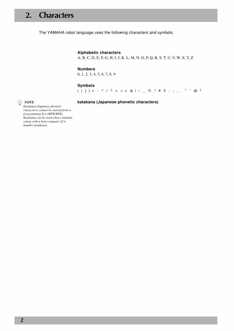
The YAMAHA robot language uses the following characters and symbols.
Alphabetic charactersA, B, C, D, E, F, G, H, I, J, K, L, M, N, O, P, Q, R, S, T, U, V, W, X, Y, Z
Numbers0, 1, 2, 3, 4, 5, 6, 7, 8, 9
Symbols( ) [ ] + - * / ^ = < > & | ~ _ % ! # $ : ; , . ” ’ @ ?
katakana (Japanese phonetic characters)n NOTEKatakana (Japanese phoneticcharacters) cannot be entered from aprogramming box (MPB/RPB).Katakana can be used when communi-cating with a host computer (if ithandles katakana).
3
2
3. Program Names
Each program to be created in the robot controller must have its own name. The same program
name cannot be given to other programs. Program names can be up to 8 characters consisting of
a combination of alphanumeric characters and underscores ( _ ).
Functions and examples of program names having special meaning are shown below.a) FUNCTION
b) SEQUENCE
c) _SELECT
d) COMMON
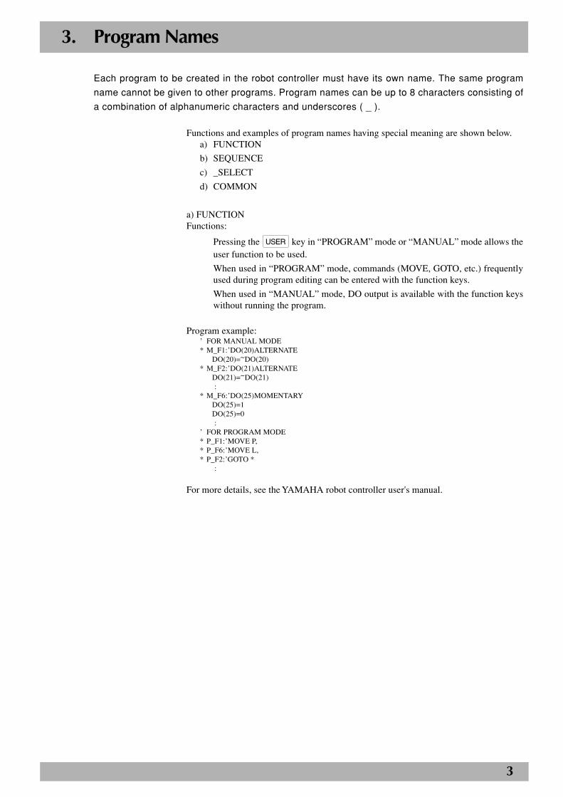
a) FUNCTIONFunctions:
Pressing the USER key in “PROGRAM” mode or “MANUAL” mode allows theuser function to be used.
When used in “PROGRAM” mode, commands (MOVE, GOTO, etc.) frequentlyused during program editing can be entered with the function keys.
When used in “MANUAL” mode, DO output is available with the function keyswithout running the program.
Program example:’ FOR MANUAL MODE* M_F1:’DO(20)ALTERNATE
DO(20)=~DO(20)* M_F2:’DO(21)ALTERNATE
DO(21)=~DO(21) :
* M_F6:’DO(25)MOMENTARYDO(25)=1DO(25)=0
:’ FOR PROGRAM MODE* P_F1:’MOVE P,* P_F6:’MOVE L,* P_F2:’GOTO *
:
For more details, see the YAMAHA robot controller user's manual.
4
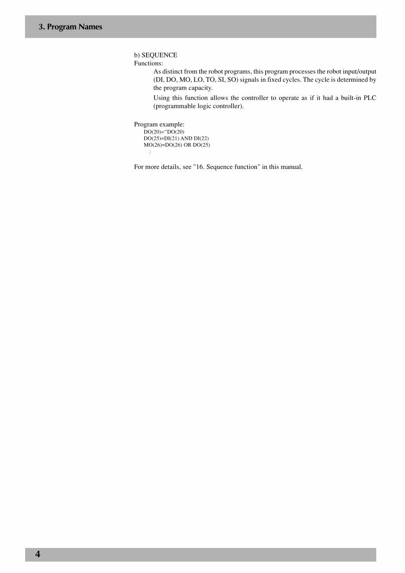
b) SEQUENCEFunctions:
As distinct from the robot programs, this program processes the robot input/output(DI, DO, MO, LO, TO, SI, SO) signals in fixed cycles. The cycle is determined bythe program capacity.
Using this function allows the controller to operate as if it had a built-in PLC(programmable logic controller).
Program example:DO(20)=~DO(20)DO(25)=DI(21) AND DI(22)MO(26)=DO(26) OR DO(25) :
For more details, see "16. Sequence function" in this manual.
3. Program Names
5
3. Program Names
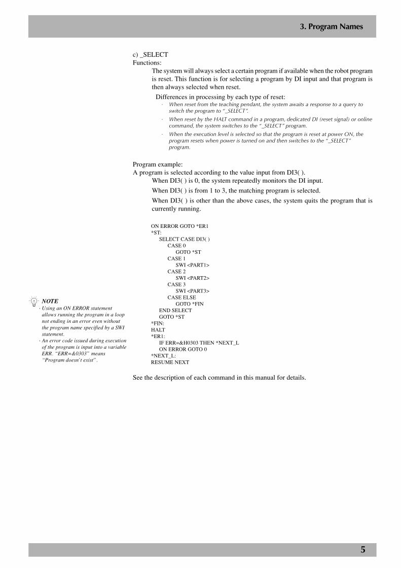
c) _SELECTFunctions:
The system will always select a certain program if available when the robot programis reset. This function is for selecting a program by DI input and that program isthen always selected when reset.
Differences in processing by each type of reset:· When reset from the teaching pendant, the system awaits a response to a query to
switch the program to “_SELECT”.
· When reset by the HALT command in a program, dedicated DI (reset signal) or onlinecommand, the system switches to the “_SELECT” program.
· When the execution level is selected so that the program is reset at power ON, theprogram resets when power is turned on and then switches to the “_SELECT”program.
Program example:A program is selected according to the value input from DI3( ).
When DI3( ) is 0, the system repeatedly monitors the DI input.
When DI3( ) is from 1 to 3, the matching program is selected.
When DI3( ) is other than the above cases, the system quits the program that iscurrently running.
ON ERROR GOTO *ER1*ST:
SELECT CASE DI3( )CASE 0
GOTO *STCASE 1
SWI <PART1>CASE 2
SWI <PART2>CASE 3
SWI <PART3>CASE ELSE
GOTO *FINEND SELECTGOTO *ST
*FIN:HALT*ER1:
IF ERR=&H0303 THEN *NEXT_LON ERROR GOTO 0
*NEXT_L:RESUME NEXT
See the description of each command in this manual for details.
n NOTE· Using an ON ERROR statement
allows running the program in a loopnot ending in an error even withoutthe program name specified by a SWIstatement.
· An error code issued during executionof the program is input into a variableERR. “ERR=&0303” means“Program doesn’t exist”.
6
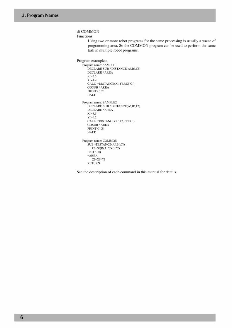
d) COMMONFunctions:
Using two or more robot programs for the same processing is usually a waste ofprogramming area. So the COMMON program can be used to perform the sametask in multiple robot programs.
Program examples:Program name: SAMPLE1
DECLARE SUB *DISTANCE(A!,B!,C!)DECLARE *AREAX!=2.5Y!=1.2CALL *DISTANCE(X!,Y!,REF C!)GOSUB *AREAPRINT C!,Z!HALT
Program name: SAMPLE2DECLARE SUB *DISTANCE(A!,B!,C!)DECLARE *AREAX!=5.5Y!=0.2CALL *DISTANCE(X!,Y!,REF C!)GOSUB *AREAPRINT C!,Z!HALT
Program name: COMMONSUB *DISTANCE(A!,B!,C!)
C!=SQR(A!^2+B!^2)END SUB*AREA:
Z!=X!*Y!RETURN
See the description of each command in this manual for details.
3. Program Names

7
4. Identifiers
The groups of characters used to express the names of labels, variables, procedures and so on are
referred to as “identifiers.”
Identifier length can be up to 16 characters composed of a combination of alphanumeric characters
and underscores ( _ ). Identifiers must begin with an alphabetic character. In the case of label
names, the character following an asterisk (*) can be a number. If an identifier exceeds 16 charac-
ters, the characters from the 17th on are ignored and deleted. A maximum of 500 identifiers can be
used.
Examples: LOOP, SUBROUTINE, GET_DATA
8
5. Command Statement Format
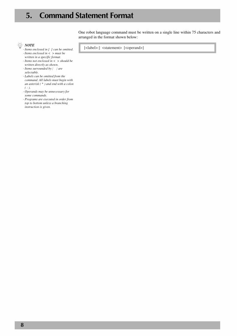
One robot language command must be written on a single line within 75 characters andarranged in the format shown below:
[<label>:] <statement> [<operand>]n NOTE· Items enclosed in [ ] can be omitted.· Items enclosed in < > must be
written in a specific format.· Items not enclosed in < > should be
written directly as shown.· Items surrounded by | | are
selectable.· Labels can be omitted from the
command. All labels must begin withan asterisk ( * ) and end with a colon( : ).
· Operands may be unnecessary forsome commands.
· Programs are executed in order fromtop to bottom unless a branchinginstruction is given.
9
6. Constants
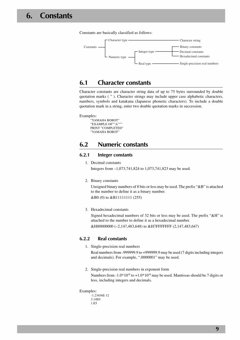
Constants are basically classified as follows:
Real type
Integer type
Constants
Single-precision real numbers
Character type
Numeric type
Character string
Binary constants
Decimal constants
Hexadecimal constants
6.1 Character constantsCharacter constants are character string data of up to 75 bytes surrounded by doublequotation marks ( ” ). Character strings may include upper case alphabetic characters,numbers, symbols and katakana (Japanese phonetic characters). To include a doublequotation mark in a string, enter two double quotation marks in succession.
Examples:”YAMAHA ROBOT””EXAMPLE OF””A”””PRINT ”COMPLETED””YAMAHA ROBOT”
6.2 Numeric constants
6.2.1 Integer constants
1. Decimal constants
Integers from –1,073,741,824 to 1,073,741,823 may be used.
2. Binary constants
Unsigned binary numbers of 8 bits or less may be used. The prefix “&B” is attachedto the number to define it as a binary number.
&B0 (0) to &B11111111 (255)
3. Hexadecimal constants
Signed hexadecimal numbers of 32 bits or less may be used. The prefix “&H” isattached to the number to define it as a hexadecimal number.
&H80000000 (–2,147,483,648) to &H7FFFFFFF (2,147,483,647)
6.2.2 Real constants
1. Single-precision real numbers
Real numbers from -999999.9 to +999999.9 may be used (7 digits including integersand decimals). For example, “.0000001” may be used.
2. Single-precision real numbers in exponent form
Numbers from -1.0*1038 to +1.0*1038 may be used. Mantissas should be 7 digits orless, including integers and decimals.
Examples:-1.23456E-123.14E01.E5
10
7. Variables
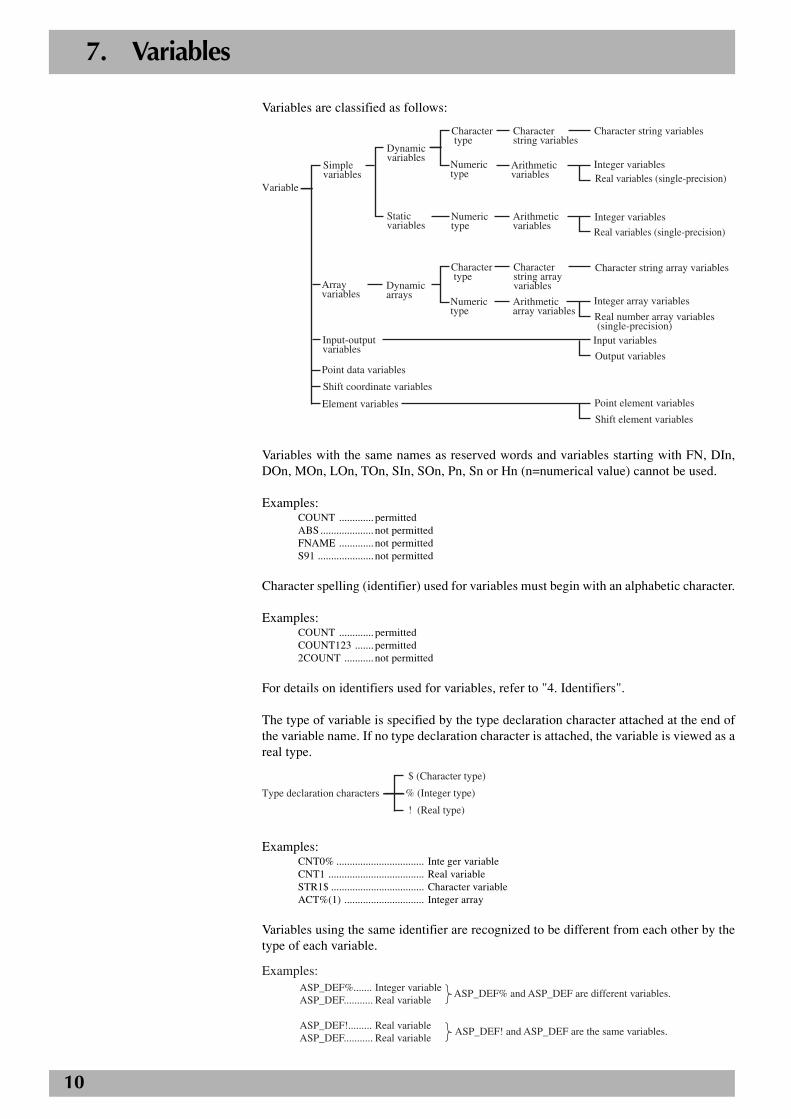
Variables are classified as follows:
Variable
Simple variables
Dynamic variables
Character type
Character string variables
Character string variables
Point data variables
Shift coordinate variables
Element variables
Input-output variables
Array variables
Dynamic arrays
Static variables
Numeric type
Numeric type
Character type
Numeric type
Arithmetic array variables
Character string array variables
Arithmetic variables
Arithmetic variables
Shift element variables
Integer variablesReal variables (single-precision)
Integer variables
Real variables (single-precision)
Character string array variables
Integer array variables
Real number array variables (single-precision)Input variables
Output variables
Point element variables
Variables with the same names as reserved words and variables starting with FN, DIn,DOn, MOn, LOn, TOn, SIn, SOn, Pn, Sn or Hn (n=numerical value) cannot be used.
Examples:COUNT ............. permittedABS .................... not permittedFNAME ............. not permittedS91 ..................... not permitted
Character spelling (identifier) used for variables must begin with an alphabetic character.
Examples:COUNT ............. permittedCOUNT123 ....... permitted2COUNT ........... not permitted
For details on identifiers used for variables, refer to "4. Identifiers".
The type of variable is specified by the type declaration character attached at the end ofthe variable name. If no type declaration character is attached, the variable is viewed as areal type.
Type declaration characters
$ (Character type)
% (Integer type)
! (Real type)
Examples:CNT0% ................................. Inte ger variableCNT1 .................................... Real variableSTR1$ ................................... Character variableACT%(1) .............................. Integer array
Variables using the same identifier are recognized to be different from each other by thetype of each variable.
Examples: ASP_DEF%....... Integer variable ASP_DEF........... Real variable
ASP_DEF!......... Real variable ASP_DEF........... Real variable
ASP_DEF% and ASP_DEF are different variables.
ASP_DEF! and ASP_DEF are the same variables.
11
7. Variables
Names of static variables are predetermined as follows:Integer type ....... S G I n (n: 0 to 7)
Real type ........... S G R n (n: 0 to 7)
7.1 Valid range of variables
7.1.1 Valid range of dynamic variables
Dynamic variables are classified into global variables and local variables according totheir declaration position in the program.
• Dynamic global variables are declared outside of sub-procedures (outside ofprogram areas enclosed by a SUB statement and END SUB statement).
• Dynamic local variables are declared within sub-procedures and are valid only inthese sub-procedures.
7.1.2 Valid range of static variables
Static variables are always valid in the entire program regardless of program statements.
7.1.3 Valid range of dynamic array variables
Dynamic array variables are classified into global array variables and local array variablesaccording to their declaration position in the program.
• Dynamic global array variables are declared outside of sub-procedures (outside ofprogram areas enclosed by a SUB statement and END SUB statement).
• Dynamic local array variables are declared within sub-procedures and are validonly in these sub-procedures.
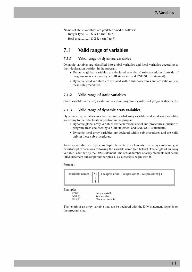
An array variable can express multiple elements. The elements of an array can be integersor subscript expressions following the variable name (see below). The length of an arrayvariable is defined by the DIM statement. The actual number of array elements will be theDIM statement subscript number plus 1, as subscripts begin with 0.
Format :
<variable name> [ % ] (<expression>, [<expression>, <expression>] ) ! $
Examples:C%(2) ........................ Integer variableN!(1,2) ...................... Real variableR1$(A) ...................... Character variable
The length of an array variable that can be declared with the DIM statement depends onthe program size.
12
7.2 Character variablesCharacter variables and character array elements can handle a character string of up to 75characters. Character strings may include alphabetic characters, numbers, symbols andkatakana (Japanese phonetic characters).
Examples:R1$ = “YAMAHA“R2$(2) = R1$ + “ MOTOR“
7.3 Numeric variables
7.3.1 Integer variables
Integer variables and integer array elements can handle an integer from –1,073,741,824to 1,073,741,823.
Examples:R1% = 10R2%(2) = R1% + 10000
7.3.2 Real variables
Real variables and real array elements can handle a real number from –1.0*1038 to 1.0*1038.
Examples:R1! = 10.31R2!(2)= R1% + 1.98E3
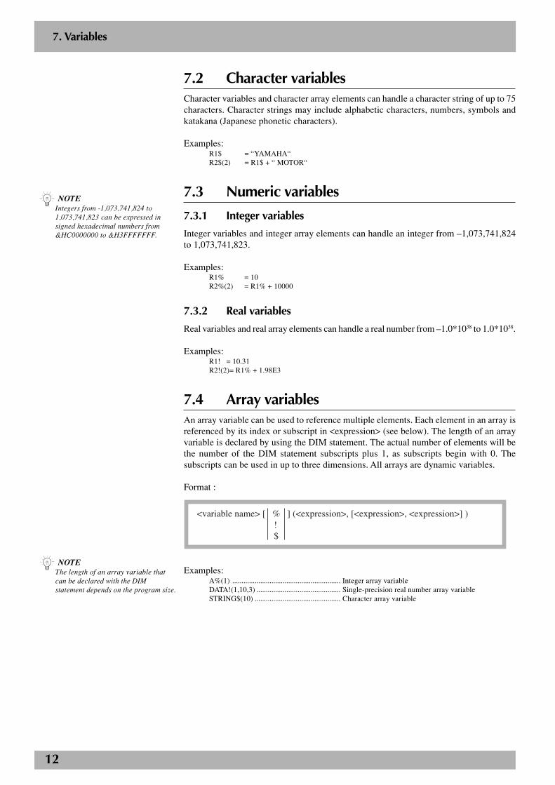
7.4 Array variablesAn array variable can be used to reference multiple elements. Each element in an array isreferenced by its index or subscript in <expression> (see below). The length of an arrayvariable is declared by using the DIM statement. The actual number of elements will bethe number of the DIM statement subscripts plus 1, as subscripts begin with 0. Thesubscripts can be used in up to three dimensions. All arrays are dynamic variables.
Format :
<variable name> [ % ] (<expression>, [<expression>, <expression>] ) ! $
Examples:A%(1) .......................................................... Integer array variableDATA!(1,10,3) ............................................. Single-precision real number array variableSTRING$(10) .............................................. Character array variable
7. Variables
n NOTEThe length of an array variable thatcan be declared with the DIMstatement depends on the program size.
n NOTEIntegers from -1,073,741,824 to1,073,741,823 can be expressed insigned hexadecimal numbers from&HC0000000 to &H3FFFFFFF.
13
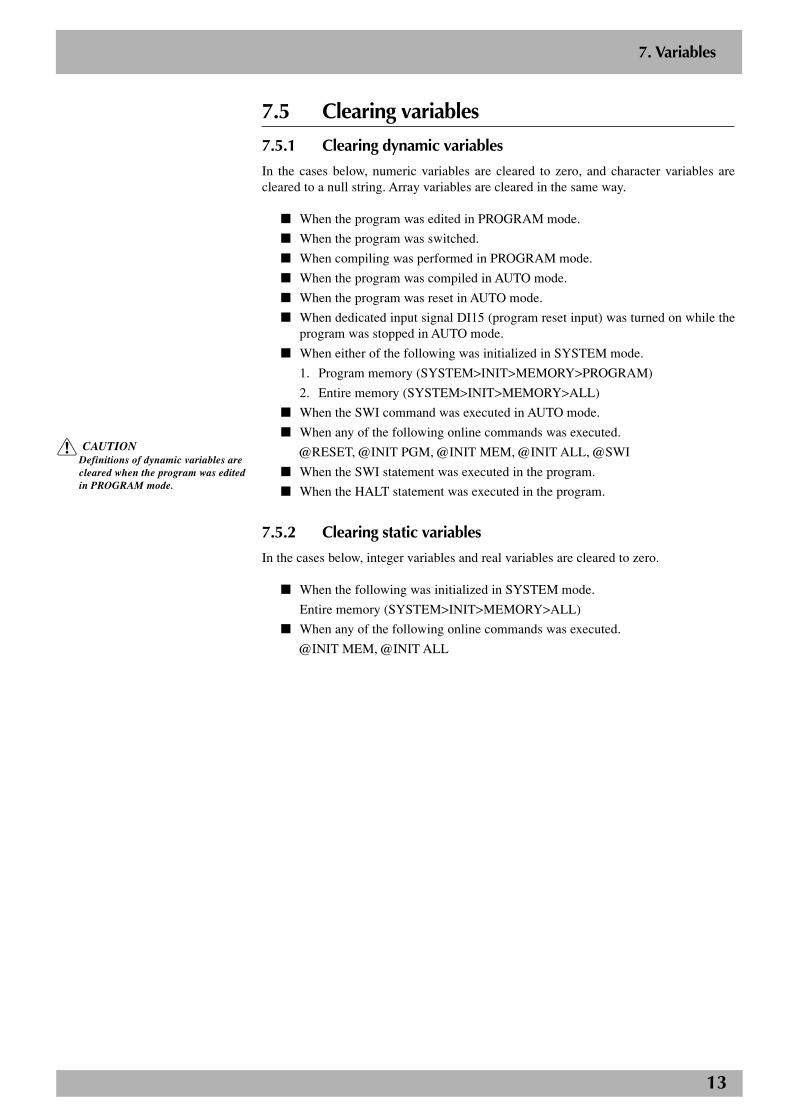
7.5 Clearing variables
7.5.1 Clearing dynamic variables
In the cases below, numeric variables are cleared to zero, and character variables arecleared to a null string. Array variables are cleared in the same way.
■ When the program was edited in PROGRAM mode.
■ When the program was switched.
■ When compiling was performed in PROGRAM mode.
■ When the program was compiled in AUTO mode.
■ When the program was reset in AUTO mode.
■ When dedicated input signal DI15 (program reset input) was turned on while theprogram was stopped in AUTO mode.
■ When either of the following was initialized in SYSTEM mode.
1. Program memory (SYSTEM>INIT>MEMORY>PROGRAM)
2. Entire memory (SYSTEM>INIT>MEMORY>ALL)
■ When the SWI command was executed in AUTO mode.
■ When any of the following online commands was executed.
@RESET, @INIT PGM, @INIT MEM, @INIT ALL, @SWI
■ When the SWI statement was executed in the program.
■ When the HALT statement was executed in the program.
7.5.2 Clearing static variables
In the cases below, integer variables and real variables are cleared to zero.
■ When the following was initialized in SYSTEM mode.
Entire memory (SYSTEM>INIT>MEMORY>ALL)
■ When any of the following online commands was executed.
@INIT MEM, @INIT ALL
7. Variables
c CAUTIONDefinitions of dynamic variables arecleared when the program was editedin PROGRAM mode.
14
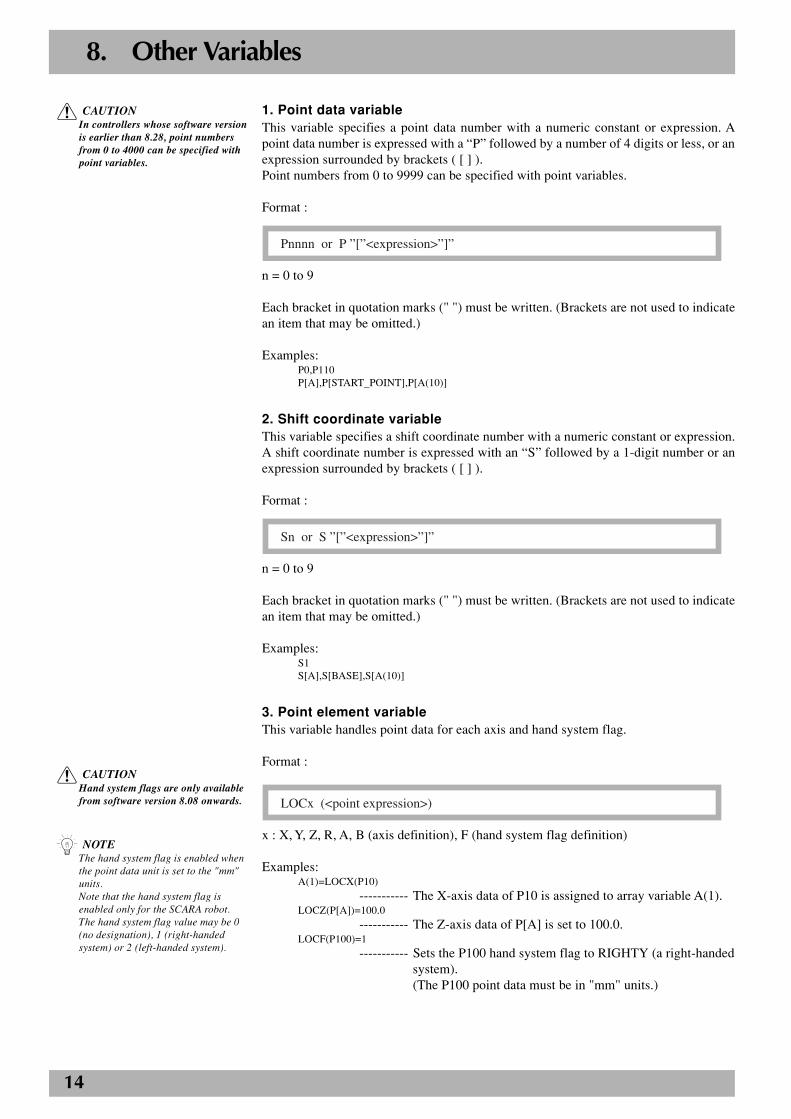
8. Other Variables
1. Point data variableThis variable specifies a point data number with a numeric constant or expression. Apoint data number is expressed with a “P” followed by a number of 4 digits or less, or anexpression surrounded by brackets ( [ ] ).Point numbers from 0 to 9999 can be specified with point variables.
Format :
Pnnnn or P ”[”<expression>”]”
n = 0 to 9
Each bracket in quotation marks (" ") must be written. (Brackets are not used to indicatean item that may be omitted.)
Examples:P0,P110P[A],P[START_POINT],P[A(10)]
2. Shift coordinate variableThis variable specifies a shift coordinate number with a numeric constant or expression.A shift coordinate number is expressed with an “S” followed by a 1-digit number or anexpression surrounded by brackets ( [ ] ).
Format :
Sn or S ”[”<expression>”]”
n = 0 to 9
Each bracket in quotation marks (" ") must be written. (Brackets are not used to indicatean item that may be omitted.)
Examples:S1S[A],S[BASE],S[A(10)]
3. Point element variableThis variable handles point data for each axis and hand system flag.
Format :LOCx
LOCx (<point expression>)
x : X, Y, Z, R, A, B (axis definition), F (hand system flag definition)
Examples:A(1)=LOCX(P10)
----------- The X-axis data of P10 is assigned to array variable A(1).LOCZ(P[A])=100.0
----------- The Z-axis data of P[A] is set to 100.0.LOCF(P100)=1
----------- Sets the P100 hand system flag to RIGHTY (a right-handedsystem).(The P100 point data must be in "mm" units.)
n NOTEThe hand system flag is enabled whenthe point data unit is set to the "mm"units.Note that the hand system flag isenabled only for the SCARA robot.The hand system flag value may be 0(no designation), 1 (right-handedsystem) or 2 (left-handed system).
c CAUTIONIn controllers whose software versionis earlier than 8.28, point numbersfrom 0 to 4000 can be specified withpoint variables.
c CAUTIONHand system flags are only availablefrom software version 8.08 onwards.
15
8. Other Variables
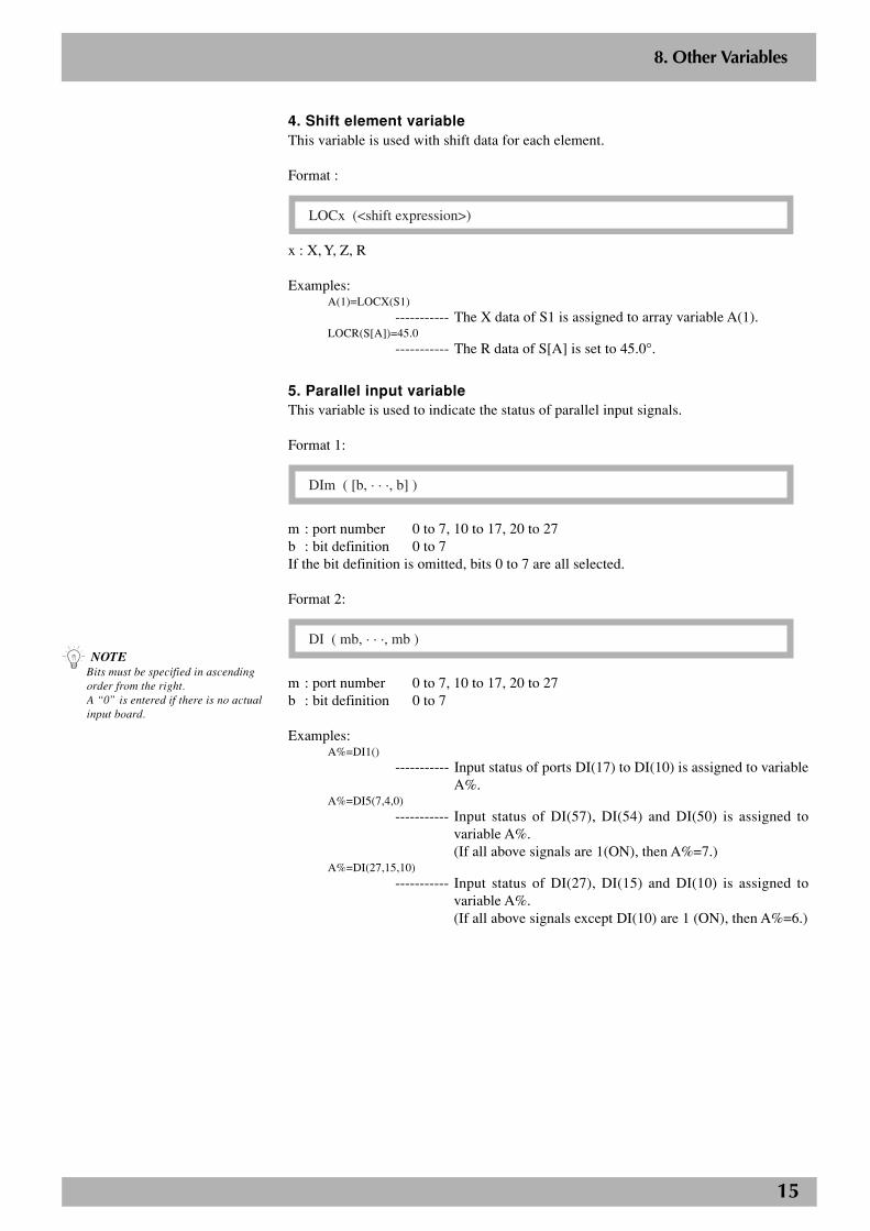
4. Shift element variableThis variable is used with shift data for each element.
Format :
LOCx (<shift expression>)
x : X, Y, Z, R
Examples:A(1)=LOCX(S1)
----------- The X data of S1 is assigned to array variable A(1).LOCR(S[A])=45.0
----------- The R data of S[A] is set to 45.0°.
5. Parallel input variableThis variable is used to indicate the status of parallel input signals.
Format 1:
DIm ( [b, · · ·, b] )
m : port number 0 to 7, 10 to 17, 20 to 27b : bit definition 0 to 7If the bit definition is omitted, bits 0 to 7 are all selected.
Format 2:
DI ( mb, · · ·, mb )
m : port number 0 to 7, 10 to 17, 20 to 27b : bit definition 0 to 7
Examples:A%=DI1()
----------- Input status of ports DI(17) to DI(10) is assigned to variableA%.
A%=DI5(7,4,0)
----------- Input status of DI(57), DI(54) and DI(50) is assigned tovariable A%.(If all above signals are 1(ON), then A%=7.)
A%=DI(27,15,10)----------- Input status of DI(27), DI(15) and DI(10) is assigned to
variable A%.(If all above signals except DI(10) are 1 (ON), then A%=6.)
n NOTEBits must be specified in ascendingorder from the right.A “0” is entered if there is no actualinput board.
16
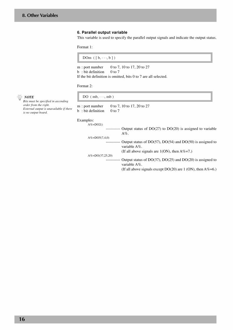
6. Parallel output variableThis variable is used to specify the parallel output signals and indicate the output status.
Format 1:
DOm ( [ b, · · ·, b ] )
m : port number 0 to 7, 10 to 17, 20 to 27b : bit definition 0 to 7If the bit definition is omitted, bits 0 to 7 are all selected.
Format 2:
DO ( mb, · · ·, mb )
m : port number 0 to 7, 10 to 17, 20 to 27b : bit definition 0 to 7
Examples:A%=DO2()
----------- Output status of DO(27) to DO(20) is assigned to variableA%.
A%=DO5(7,4,0)
----------- Output status of DO(57), DO(54) and DO(50) is assigned tovariable A%.(If all above signals are 1(ON), then A%=7.)
A%=DO(37,25,20)
----------- Output status of DO(37), DO(25) and DO(20) is assigned tovariable A%.(If all above signals except DO(20) are 1 (ON), then A%=6.)
n NOTEBits must be specified in ascendingorder from the right.External output is unavailable if thereis no output board.
8. Other Variables
17
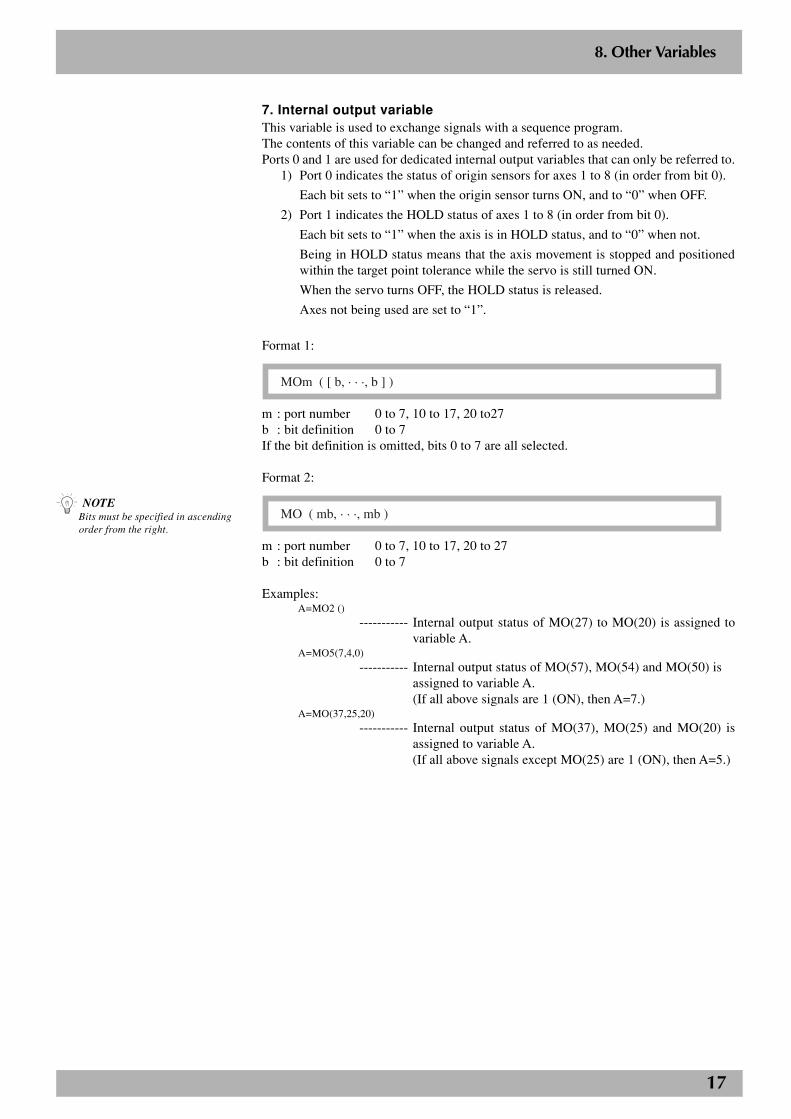
7. Internal output variableThis variable is used to exchange signals with a sequence program.The contents of this variable can be changed and referred to as needed.Ports 0 and 1 are used for dedicated internal output variables that can only be referred to.
1) Port 0 indicates the status of origin sensors for axes 1 to 8 (in order from bit 0).
Each bit sets to “1” when the origin sensor turns ON, and to “0” when OFF.
2) Port 1 indicates the HOLD status of axes 1 to 8 (in order from bit 0).
Each bit sets to “1” when the axis is in HOLD status, and to “0” when not.
Being in HOLD status means that the axis movement is stopped and positionedwithin the target point tolerance while the servo is still turned ON.
When the servo turns OFF, the HOLD status is released.
Axes not being used are set to “1”.
Format 1:
MOm ( [ b, · · ·, b ] )
m : port number 0 to 7, 10 to 17, 20 to27b : bit definition 0 to 7If the bit definition is omitted, bits 0 to 7 are all selected.
Format 2:
MO ( mb, · · ·, mb )
m : port number 0 to 7, 10 to 17, 20 to 27b : bit definition 0 to 7
Examples:A=MO2 ()
----------- Internal output status of MO(27) to MO(20) is assigned tovariable A.
A=MO5(7,4,0)----------- Internal output status of MO(57), MO(54) and MO(50) is
assigned to variable A.(If all above signals are 1 (ON), then A=7.)
A=MO(37,25,20)----------- Internal output status of MO(37), MO(25) and MO(20) is
assigned to variable A.(If all above signals except MO(25) are 1 (ON), then A=5.)
n NOTEBits must be specified in ascendingorder from the right.
8. Other Variables
18
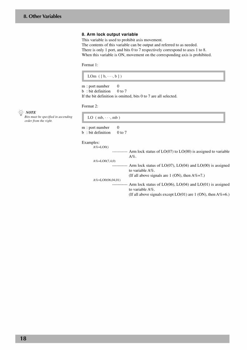
8. Arm lock output variableThis variable is used to prohibit axis movement.The contents of this variable can be output and referred to as needed.There is only 1 port, and bits 0 to 7 respectively correspond to axes 1 to 8.When this variable is ON, movement on the corresponding axis is prohibited.
Format 1:
LOm ( [ b, · · ·, b ] )
m : port number 0b : bit definition 0 to 7If the bit definition is omitted, bits 0 to 7 are all selected.
Format 2:
LO ( mb, · · ·, mb )
m : port number 0b : bit definition 0 to 7
Examples:A%=LO0()
----------- Arm lock status of LO(07) to LO(00) is assigned to variableA%.
A%=LO0(7,4,0)
----------- Arm lock status of LO(07), LO(04) and LO(00) is assignedto variable A%.(If all above signals are 1 (ON), then A%=7.)
A%=LO0(06,04,01)
----------- Arm lock status of LO(06), LO(04) and LO(01) is assignedto variable A%.(If all above signals except LO(01) are 1 (ON), then A%=6.)
8. Other Variables
n NOTEBits must be specified in ascendingorder from the right.
19
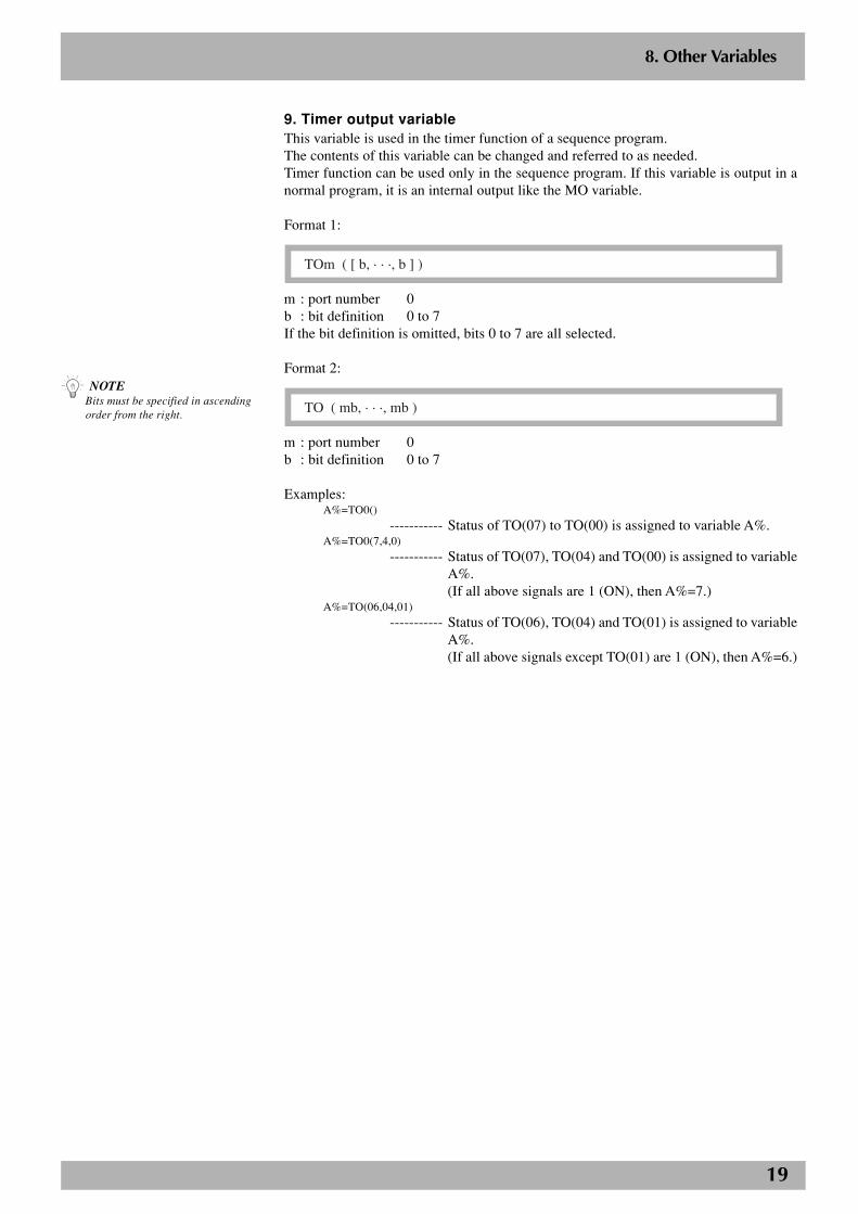
9. Timer output variableThis variable is used in the timer function of a sequence program.The contents of this variable can be changed and referred to as needed.Timer function can be used only in the sequence program. If this variable is output in anormal program, it is an internal output like the MO variable.
Format 1:
TOm ( [ b, · · ·, b ] )
m : port number 0b : bit definition 0 to 7If the bit definition is omitted, bits 0 to 7 are all selected.
Format 2:
TO ( mb, · · ·, mb )
m : port number 0b : bit definition 0 to 7
Examples:A%=TO0()
----------- Status of TO(07) to TO(00) is assigned to variable A%.A%=TO0(7,4,0)
----------- Status of TO(07), TO(04) and TO(00) is assigned to variableA%.(If all above signals are 1 (ON), then A%=7.)
A%=TO(06,04,01)
----------- Status of TO(06), TO(04) and TO(01) is assigned to variableA%.(If all above signals except TO(01) are 1 (ON), then A%=6.)
8. Other Variables
n NOTEBits must be specified in ascendingorder from the right.
20
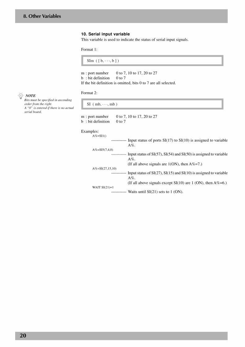
10. Serial input variableThis variable is used to indicate the status of serial input signals.
Format 1:
SIm ( [ b, · · ·, b ] )
m : port number 0 to 7, 10 to 17, 20 to 27b : bit definition 0 to 7If the bit definition is omitted, bits 0 to 7 are all selected.
Format 2:
SI ( mb, · · ·, mb )
m : port number 0 to 7, 10 to 17, 20 to 27b : bit definition 0 to 7
Examples:A%=SI1()
----------- Input status of ports SI(17) to SI(10) is assigned to variableA%.
A%=SI5(7,4,0)
----------- Input status of SI(57), SI(54) and SI(50) is assigned to variableA%.(If all above signals are 1(ON), then A%=7.)
A%=SI(27,15,10)
----------- Input status of SI(27), SI(15) and SI(10) is assigned to variableA%.(If all above signals except SI(10) are 1 (ON), then A%=6.)
WAIT SI(21)=1
----------- Waits until SI(21) sets to 1 (ON).
8. Other Variables
n NOTEBits must be specified in ascendingorder from the right.A “0” is entered if there is no actualserial board.
21
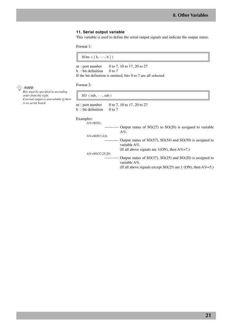
11. Serial output variableThis variable is used to define the serial output signals and indicate the output status.
Format 1:
SOm ( [ b, · · ·, b ] )
m : port number 0 to 7, 10 to 17, 20 to 27b : bit definition 0 to 7If the bit definition is omitted, bits 0 to 7 are all selected.
Format 2:
SO ( mb, · · ·, mb )
m : port number 0 to 7, 10 to 17, 20 to 27b : bit definition 0 to 7
Examples:A%=SO2()
----------- Output status of SO(27) to SO(20) is assigned to variableA%.
A%=SO5(7,4,0)
----------- Output status of SO(57), SO(54) and SO(50) is assigned tovariable A%.(If all above signals are 1(ON), then A%=7.)
A%=SO(37,25,20)
----------- Output status of SO(37), SO(25) and SO(20) is assigned tovariable A%.(If all above signals except SO(25) are 1 (ON), then A%=5.)
8. Other Variables
n NOTEBits must be specified in ascendingorder from the right.External output is unavailable if thereis no serial board.
22
2
8. Other Variables
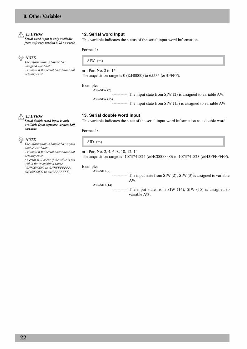
12. Serial word inputThis variable indicates the status of the serial input word information.
Format 1:
SIW (m)
m : Port No. 2 to 15The acquisition range is 0 (&H0000) to 65535 (&HFFFF).
Example:A%=SIW (2)
----------- The input state from SIW (2) is assigned to variable A%.A%=SIW (15)
----------- The input state from SIW (15) is assigned to variable A%.
13. Serial double word inputThis variable indicates the state of the serial input word information as a double word.
Format 1:
SID (m)
m : Port No. 2, 4, 6, 8, 10, 12, 14The acquisition range is -1073741824 (&HC0000000) to 1073741823 (&H3FFFFFFF).
Example:A%=SID (2)
----------- The input state from SIW (2) , SIW (3) is assigned to variableA%.
A%=SID (14)
----------- The input state from SIW (14), SIW (15) is assigned tovariable A%.
n NOTEThe information is handled asunsigned word data.0 is input if the serial board does notactually exist.
n NOTEThe information is handled as signeddouble word data.0 is input if the serial board does notactually exist.An error will occur if the value is notwithin the acquisition range(&H80000000 to &HBFFFFFFF,&H40000000 to &H7FFFFFFF.)
c CAUTIONSerial word input is only availablefrom software version 8.08 onwards.
c CAUTIONSerial double word input is onlyavailable from software version 8.08onwards.
23
2
8. Other Variables
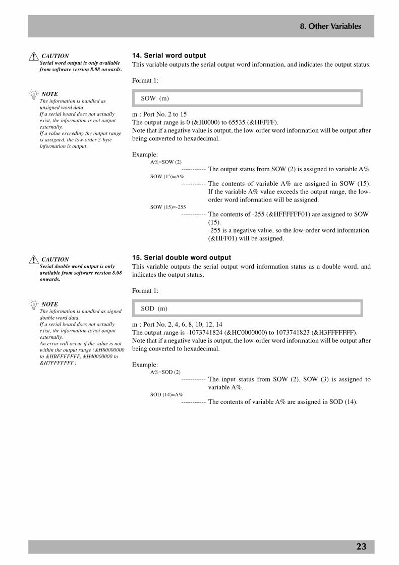
14. Serial word outputThis variable outputs the serial output word information, and indicates the output status.
Format 1:
SOW (m)
m : Port No. 2 to 15The output range is 0 (&H0000) to 65535 (&HFFFF).Note that if a negative value is output, the low-order word information will be output afterbeing converted to hexadecimal.
Example:A%=SOW (2)
----------- The output status from SOW (2) is assigned to variable A%.SOW (15)=A%
----------- The contents of variable A% are assigned in SOW (15).If the variable A% value exceeds the output range, the low-order word information will be assigned.
SOW (15)=-255----------- The contents of -255 (&HFFFFFF01) are assigned to SOW
(15).-255 is a negative value, so the low-order word information(&HFF01) will be assigned.
15. Serial double word outputThis variable outputs the serial output word information status as a double word, andindicates the output status.
Format 1:
SOD (m)
m : Port No. 2, 4, 6, 8, 10, 12, 14The output range is -1073741824 (&HC0000000) to 1073741823 (&H3FFFFFFF).Note that if a negative value is output, the low-order word information will be output afterbeing converted to hexadecimal.
Example:A%=SOD (2)
----------- The input status from SOW (2), SOW (3) is assigned tovariable A%.
SOD (14)=A%
----------- The contents of variable A% are assigned in SOD (14).
n NOTEThe information is handled asunsigned word data.If a serial board does not actuallyexist, the information is not outputexternally.If a value exceeding the output rangeis assigned, the low-order 2-byteinformation is output.
n NOTEThe information is handled as signeddouble word data.If a serial board does not actuallyexist, the information is not outputexternally.An error will occur if the value is notwithin the output range (&H80000000to &HBFFFFFFF, &H40000000 to&H7FFFFFFF.)
c CAUTIONSerial word output is only availablefrom software version 8.08 onwards.
c CAUTIONSerial double word output is onlyavailable from software version 8.08onwards.
24
9. Expressions and Operations
9.1 Arithmetic operations
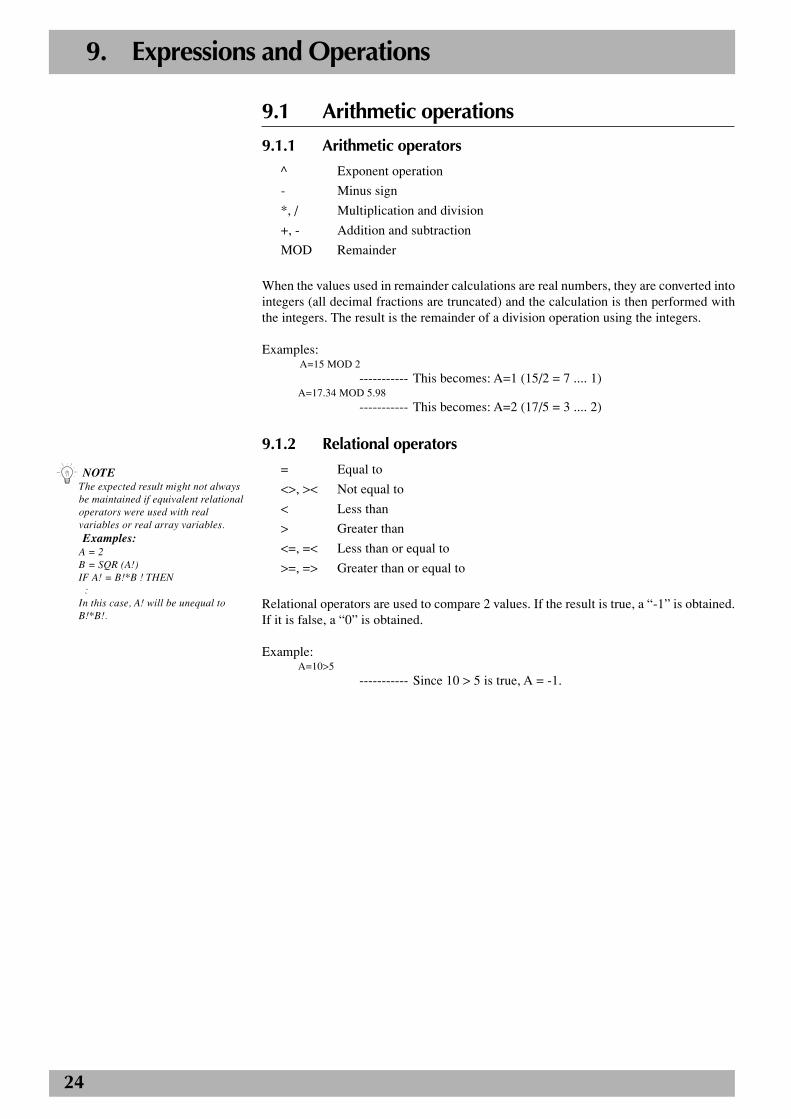
9.1.1 Arithmetic operators
^ Exponent operation
- Minus sign
*, / Multiplication and division
+, - Addition and subtraction
MOD Remainder
When the values used in remainder calculations are real numbers, they are converted intointegers (all decimal fractions are truncated) and the calculation is then performed withthe integers. The result is the remainder of a division operation using the integers.
Examples:A=15 MOD 2
----------- This becomes: A=1 (15/2 = 7 .... 1)A=17.34 MOD 5.98
----------- This becomes: A=2 (17/5 = 3 .... 2)
9.1.2 Relational operators
= Equal to
<>, >< Not equal to
< Less than
> Greater than
<=, =< Less than or equal to
>=, => Greater than or equal to
Relational operators are used to compare 2 values. If the result is true, a “-1” is obtained.If it is false, a “0” is obtained.
Example:A=10>5
----------- Since 10 > 5 is true, A = -1.
n NOTEThe expected result might not alwaysbe maintained if equivalent relationaloperators were used with realvariables or real array variables.Examples:
A = 2B = SQR (A!)IF A! = B!*B ! THEN :In this case, A! will be unequal toB!*B!.
25
9.1.3 Logic operations
NOT, ~ Logical NOT
AND, & Logical AND
OR, | Logical OR
XOR Exclusive OR
Logic operators are used to manipulate 1 or 2 values bit by bit. For example, the status ofan I/O port can be manipulated. Depending on the logic operation performed, the resultsgenerated are either “0” or “1”. Logic operations with real numbers convert the valuesinto integers before they are executed.
Examples:A%=NOT 13.05
----------- Each bit of 13 is reversed, and the result “–14” is assigned toA%.
A%=3 AND 10
----------- The logical product of 3 and 10 is calculated (“1” is obtainedwhen both bits are “1”), and the result is assigned to A%, soA% becomes 2.
A%=3 OR 10
----------- The logical sum of 3 and 10 is calculated (“1” is obtainedwhen either bit is “1”), and the result is assigned to A%, soA% becomes 11.
A%=3 XOR 10
----------- The exclusive OR of 3 and 10 is calculated (“1” is obtainedwhen both bits are different from each other), and the resultis assigned to A%, so A% becomes 9.
9.1.4 Priority of arithmetic operation
1. Expressions included in parentheses
2. Functions, variables
3. ^ (exponents)
4. Independent “+” and “-” signs (monominal operators)
5. * (multiplication), / (division)
6. MOD
7. + (addition), - (subtraction)
8. Relational operators
9. NOT, ~ (Logical NOT)
10. AND, & (logical AND)
11. OR, |, XOR (Logical OR, exclusive OR)
Operations are performed in the above order of priority. When two operations of equalpriority appear in the same statement, the operations are executed in order from left toright.
9. Expressions and Operations
26
9.1.5 Data format conversion
Data format is converted in cases where two values of different formats are involved inthe same operation.
1) When a real number is assigned to an integer, decimal places are rounded off.
Example: A %=125.67 ------------- A% = 126
2) When integers and real numbers are involved in the same operation, the resultbecomes a real number.
Example: A (0) =125* 0.25 ------- A (0) =31.25
3) When an integer is divided by an integer, the result is an integer.
Example: A (0) =100/3 ------------- A (0) = 33
9.2 Character string operations
9.2.1 Character string connection
Character strings may be combined by using the “+” sign.
Examples:A$=”YAMAHA”B$=”ROBOT”C$=”LANGUAGE”D$=”MOUNTER”E$=A$+” ”+B$+” ”+C$F$=A$+” ”+D$PRINT E$PRINT F$
Results: YAMAHA ROBOT LANGUAGEYAMAHA MOUNTER
9.2.2 Character string comparison
Characters can be compared with the same relational operators as used for numeric values.In the case of character strings, the comparison is performed from the beginning of eachstring, character by character. If all characters match in both strings, they are consideredto be equal. Even if only one character in the string differs from its corresponding characterin the other string, then the string with the larger (higher) character code is treated as thelarger string.If one string is shorter than the other, it is judged to be the string of lesser value.
All examples below are “true”.
Examples:”AA”<”AB””X&”>”X#””DESK"<”DESKS”
Character string comparison can be used to find out the contents of character strings, or tosort character strings into alphabetical order.
9. Expressions and Operations
27
9.3 Point data formatThere are two types of point data formats: joint coordinate format and Cartesian coordi-nate format.Point numbers are in the range of 0 to 9999.
9.3.1 Joint coordinate format
± n n n n n n n (same for X, Y, Z, R, A, B axes)This is a decimal integer constant of 7 digits or less with a plus or minus sign, and can bespecified from –6144000 to 6144000. (Unit: pulses)
9.3.2 Cartesian coordinate format
± n n n . n n to ± n n n n n n n. (same for X, Y, Z, R, A, B axes)This is a decimal fraction of a total of 7 digits including 2 or less decimal places. (Unit:mm or degrees)When setting an extended hand system flag for SCARA robots, set either 1 or 2 at the endof the data. If a value other than 1 or 2 is set, or if no value is designated, 0 will be set toindicate that no hand system flag is set.
1: RIGHTY (right-handed system) 2: LEFTY (left-handed system)
9.4 DI/DO conditional expressionsDI/DO conditional expressions may be used to set conditions for WAIT statements andSTOPON options in MOVE statements. Numeric constants, variables and arithmeticoperators that may be used with DI/DO conditional expressions are shown below.
a. Constant
Decimal integer constant, binary integer constant, hexadecimal integer constant
b. Variables
Global integer type, global real number type, input/output type
c. Operators
Relational operators, logic operators
d. Operation priority
1. Relational operators
2. NOT, ~
3. AND, &
4. OR, |, XOR
Example: WAIT DI(31)=1 OR DI(34)=1
----------- The program waits until either DI31 or DI34 turns ON.
n NOTEPlus (+) signs can be omitted.
9. Expressions and Operations
c CAUTIONIn controllers whose software versionis earlier than 8.28, the range of pointnumbers is from 0 to 4000.
c CAUTIONHand system flags are only availablefrom software version 8.08 onwards.
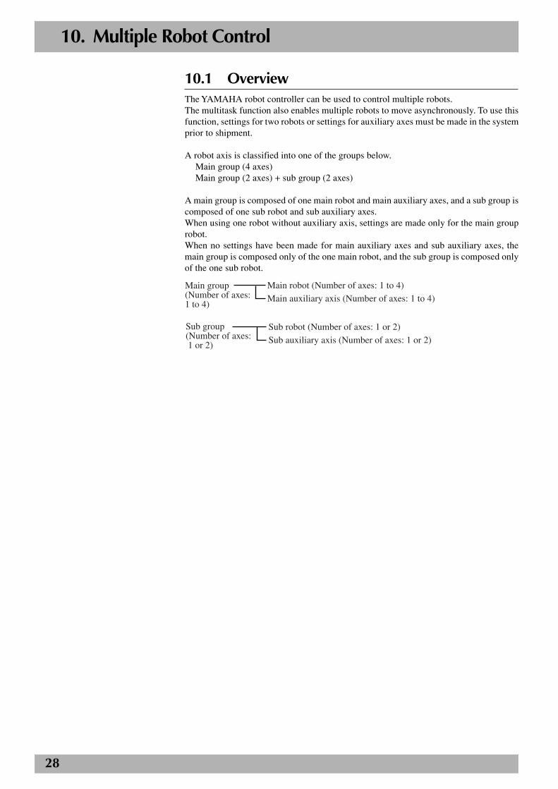
28
10. Multiple Robot Control
10.1 OverviewThe YAMAHA robot controller can be used to control multiple robots.The multitask function also enables multiple robots to move asynchronously. To use thisfunction, settings for two robots or settings for auxiliary axes must be made in the systemprior to shipment.
A robot axis is classified into one of the groups below.Main group (4 axes)Main group (2 axes) + sub group (2 axes)
A main group is composed of one main robot and main auxiliary axes, and a sub group iscomposed of one sub robot and sub auxiliary axes.When using one robot without auxiliary axis, settings are made only for the main grouprobot.When no settings have been made for main auxiliary axes and sub auxiliary axes, themain group is composed only of the one main robot, and the sub group is composed onlyof the one sub robot.
Main robot (Number of axes: 1 to 4)
Main auxiliary axis (Number of axes: 1 to 4)Main group (Number of axes: 1 to 4)
Sub robot (Number of axes: 1 or 2)
Sub auxiliary axis (Number of axes: 1 or 2)
Sub group(Number of axes: 1 or 2)
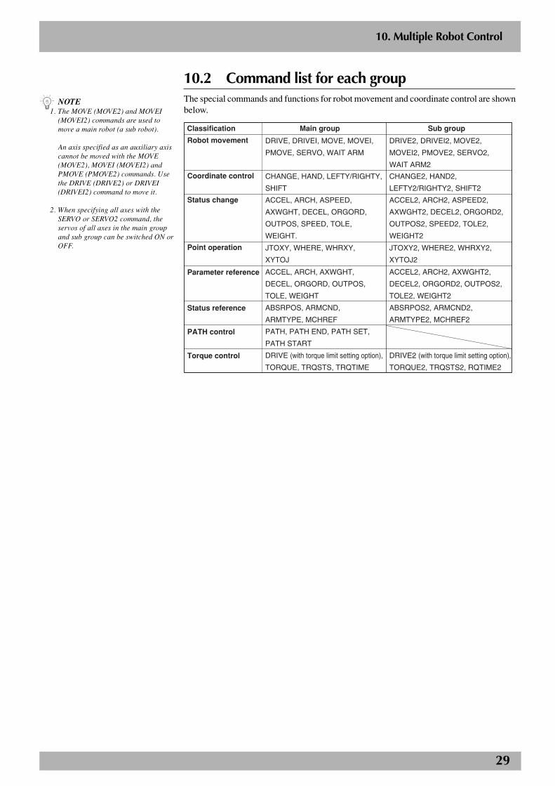
29
n NOTE1. The MOVE (MOVE2) and MOVEI
(MOVEI2) commands are used tomove a main robot (a sub robot).
An axis specified as an auxiliary axiscannot be moved with the MOVE(MOVE2), MOVEI (MOVEI2) andPMOVE (PMOVE2) commands. Usethe DRIVE (DRIVE2) or DRIVEI(DRIVEI2) command to move it.
2. When specifying all axes with theSERVO or SERVO2 command, theservos of all axes in the main groupand sub group can be switched ON orOFF.
10. Multiple Robot Control
10.2 Command list for each groupThe special commands and functions for robot movement and coordinate control are shownbelow.
Classification Main group Sub group
Robot movement DRIVE, DRIVEI, MOVE, MOVEI,
PMOVE, SERVO, WAIT ARM
DRIVE2, DRIVEI2, MOVE2,
MOVEI2, PMOVE2, SERVO2,
WAIT ARM2
Coordinate control CHANGE, HAND, LEFTY/RIGHTY,
SHIFT
CHANGE2, HAND2,
LEFTY2/RIGHTY2, SHIFT2
Status change ACCEL, ARCH, ASPEED,
AXWGHT, DECEL, ORGORD,
OUTPOS, SPEED, TOLE,
WEIGHT.
ACCEL2, ARCH2, ASPEED2,
AXWGHT2, DECEL2, ORGORD2,
OUTPOS2, SPEED2, TOLE2,
WEIGHT2
Point operation JTOXY, WHERE, WHRXY,
XYTOJ
JTOXY2, WHERE2, WHRXY2,
XYTOJ2
Parameter reference
Status reference
ACCEL, ARCH, AXWGHT,
DECEL, ORGORD, OUTPOS,
TOLE, WEIGHT
ABSRPOS, ARMCND,
ARMTYPE, MCHREF
ACCEL2, ARCH2, AXWGHT2,
DECEL2, ORGORD2, OUTPOS2,
TOLE2, WEIGHT2
ABSRPOS2, ARMCND2,
ARMTYPE2, MCHREF2
PATH control PATH, PATH END, PATH SET,
PATH START
Torque control DRIVE (with torque limit setting option),
TORQUE, TRQSTS, TRQTIME
DRIVE2 (with torque limit setting option),
TORQUE2, TRQSTS2, RQTIME2
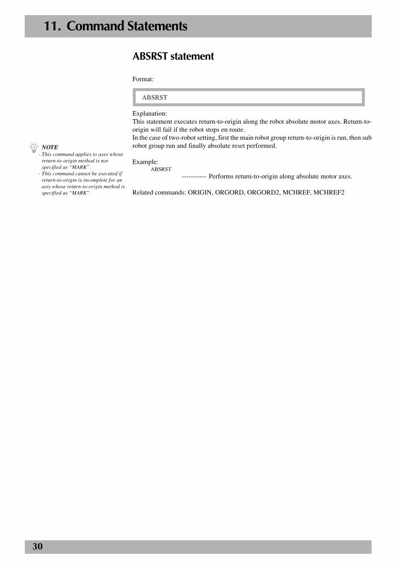
30
11. Command Statements
ABSRST statement
Format:
ABSRST
Explanation:This statement executes return-to-origin along the robot absolute motor axes. Return-to-origin will fail if the robot stops en route.In the case of two-robot setting, first the main robot group return-to-origin is run, then subrobot group run and finally absolute reset performed.
Example:ABSRST
----------- Performs return-to-origin along absolute motor axes.
Related commands: ORIGIN, ORGORD, ORGORD2, MCHREF, MCHREF2
n NOTE· This command applies to axes whose
return-to-origin method is notspecified as “MARK”.
· This command cannot be executed ifreturn-to-origin is incomplete for anaxis whose return-to-origin method isspecified as “MARK”.
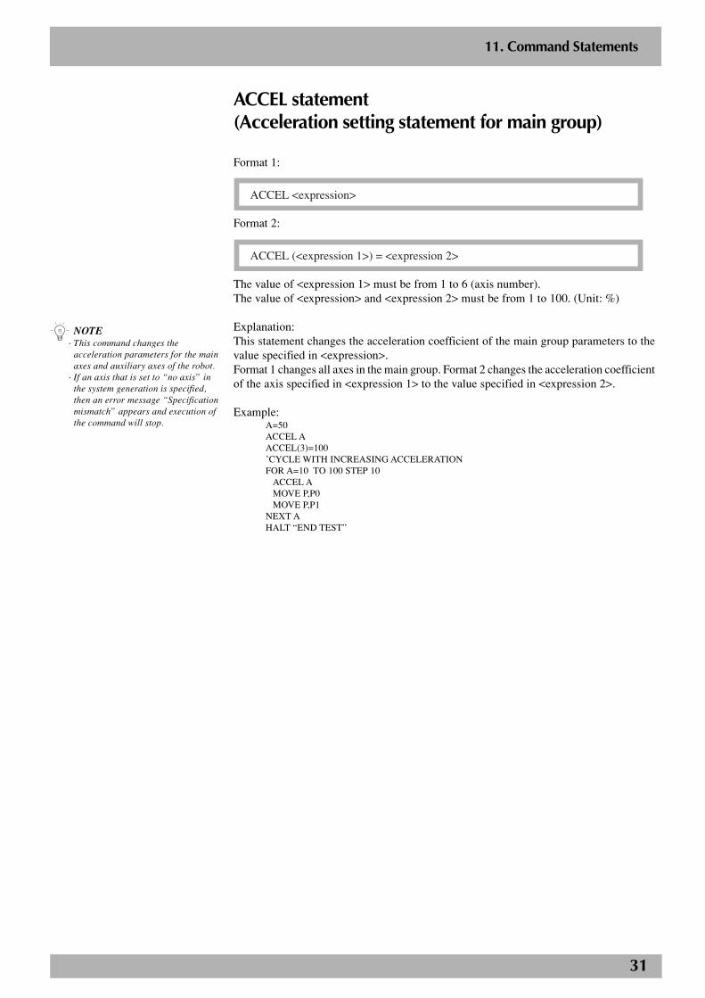
31
2
11. Command Statements
ACCEL statement(Acceleration setting statement for main group)
Format 1:
ACCEL <expression>
Format 2:
ACCEL (<expression 1>) = <expression 2>
The value of <expression 1> must be from 1 to 6 (axis number).The value of <expression> and <expression 2> must be from 1 to 100. (Unit: %)
Explanation:This statement changes the acceleration coefficient of the main group parameters to thevalue specified in <expression>.Format 1 changes all axes in the main group. Format 2 changes the acceleration coefficientof the axis specified in <expression 1> to the value specified in <expression 2>.
Example:A=50ACCEL AACCEL(3)=100’CYCLE WITH INCREASING ACCELERATIONFOR A=10 TO 100 STEP 10
ACCEL AMOVE P,P0MOVE P,P1
NEXT AHALT “END TEST”
n NOTE· This command changes the
acceleration parameters for the mainaxes and auxiliary axes of the robot.
· If an axis that is set to “no axis” inthe system generation is specified,then an error message “Specificationmismatch” appears and execution ofthe command will stop.
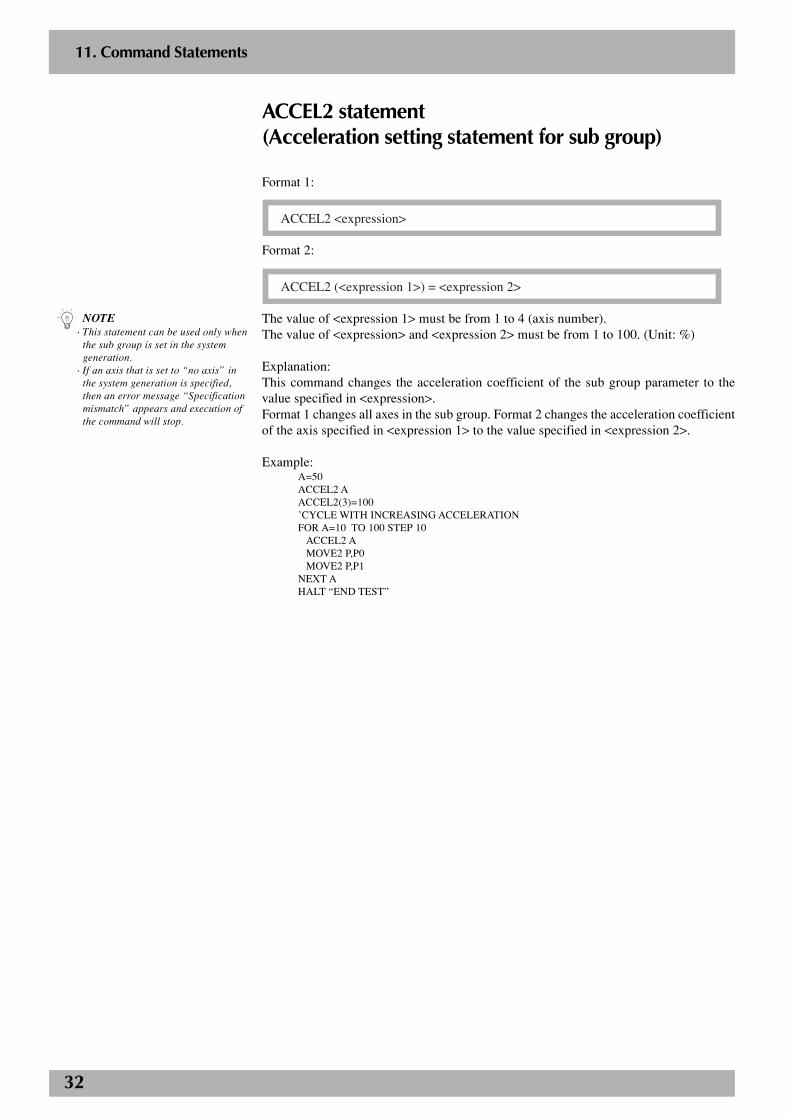
32
2
11. Command Statements
ACCEL2 statement(Acceleration setting statement for sub group)
Format 1:
ACCEL2 <expression>
Format 2:
ACCEL2 (<expression 1>) = <expression 2>
The value of <expression 1> must be from 1 to 4 (axis number).The value of <expression> and <expression 2> must be from 1 to 100. (Unit: %)
Explanation:This command changes the acceleration coefficient of the sub group parameter to thevalue specified in <expression>.Format 1 changes all axes in the sub group. Format 2 changes the acceleration coefficientof the axis specified in <expression 1> to the value specified in <expression 2>.
Example:A=50ACCEL2 AACCEL2(3)=100’CYCLE WITH INCREASING ACCELERATIONFOR A=10 TO 100 STEP 10
ACCEL2 AMOVE2 P,P0MOVE2 P,P1
NEXT AHALT “END TEST”
n NOTE· This statement can be used only when
the sub group is set in the systemgeneration.
· If an axis that is set to “no axis” inthe system generation is specified,then an error message “Specificationmismatch” appears and execution ofthe command will stop.
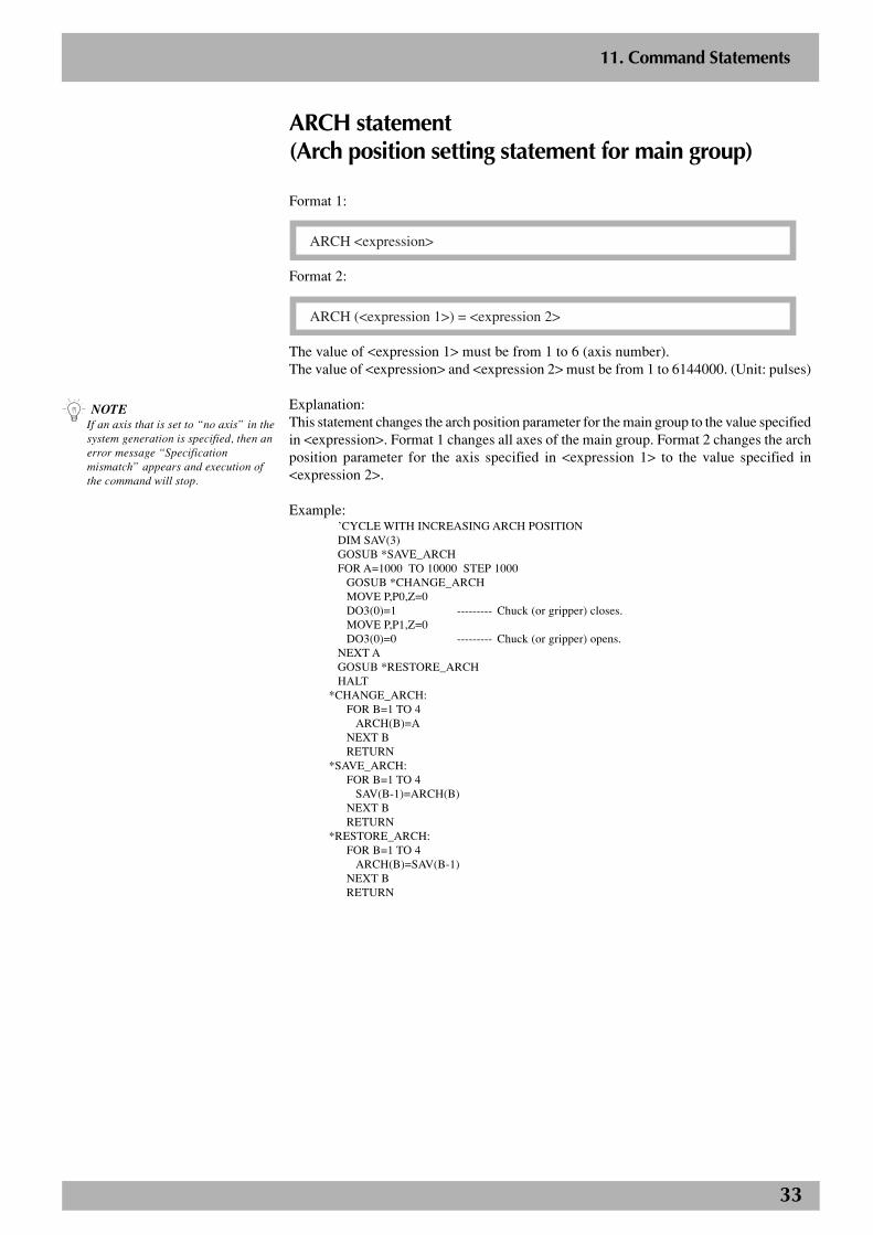
33
2
11. Command Statements
ARCH statement(Arch position setting statement for main group)
Format 1:
ARCH <expression>
Format 2:
ARCH (<expression 1>) = <expression 2>
The value of <expression 1> must be from 1 to 6 (axis number).The value of <expression> and <expression 2> must be from 1 to 6144000. (Unit: pulses)
Explanation:This statement changes the arch position parameter for the main group to the value specifiedin <expression>. Format 1 changes all axes of the main group. Format 2 changes the archposition parameter for the axis specified in <expression 1> to the value specified in<expression 2>.
Example:’CYCLE WITH INCREASING ARCH POSITIONDIM SAV(3)GOSUB *SAVE_ARCHFOR A=1000 TO 10000 STEP 1000
GOSUB *CHANGE_ARCHMOVE P,P0,Z=0DO3(0)=1 --------- Chuck (or gripper) closes.MOVE P,P1,Z=0DO3(0)=0 --------- Chuck (or gripper) opens.
NEXT AGOSUB *RESTORE_ARCHHALT
*CHANGE_ARCH:FOR B=1 TO 4
ARCH(B)=ANEXT BRETURN
*SAVE_ARCH:FOR B=1 TO 4
SAV(B-1)=ARCH(B)NEXT BRETURN
*RESTORE_ARCH:FOR B=1 TO 4
ARCH(B)=SAV(B-1)NEXT BRETURN
n NOTEIf an axis that is set to “no axis” in thesystem generation is specified, then anerror message “Specificationmismatch” appears and execution ofthe command will stop.
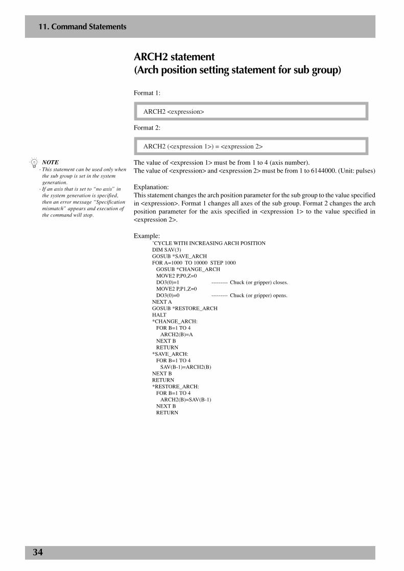
34
2
11. Command Statements
ARCH2 statement(Arch position setting statement for sub group)
Format 1:
ARCH2 <expression>
Format 2:
ARCH2 (<expression 1>) = <expression 2>
The value of <expression 1> must be from 1 to 4 (axis number).The value of <expression> and <expression 2> must be from 1 to 6144000. (Unit: pulses)
Explanation:This statement changes the arch position parameter for the sub group to the value specifiedin <expression>. Format 1 changes all axes of the sub group. Format 2 changes the archposition parameter for the axis specified in <expression 1> to the value specified in<expression 2>.
Example:’CYCLE WITH INCREASING ARCH POSITIONDIM SAV(3)GOSUB *SAVE_ARCHFOR A=1000 TO 10000 STEP 1000
GOSUB *CHANGE_ARCHMOVE2 P,P0,Z=0DO3(0)=1 --------- Chuck (or gripper) closes.MOVE2 P,P1,Z=0DO3(0)=0 --------- Chuck (or gripper) opens.
NEXT AGOSUB *RESTORE_ARCHHALT*CHANGE_ARCH:
FOR B=1 TO 4ARCH2(B)=A
NEXT BRETURN
*SAVE_ARCH:FOR B=1 TO 4
SAV(B-1)=ARCH2(B)NEXT BRETURN*RESTORE_ARCH:
FOR B=1 TO 4ARCH2(B)=SAV(B-1)
NEXT BRETURN
n NOTE· This statement can be used only when
the sub group is set in the systemgeneration.
· If an axis that is set to “no axis” inthe system generation is specified,then an error message “Specificationmismatch” appears and execution ofthe command will stop.
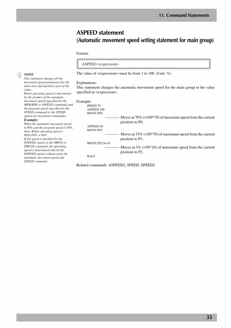
35
2
11. Command Statements
ASPEED statement(Automatic movement speed setting statement for main group)
Format:
ASPEED <expression>
The value of <expression> must be from 1 to 100. (Unit: %)
Explanation:This statement changes the automatic movement speed for the main group to the valuespecified in <expression>.
Example:SPEED 70ASPEED 100MOVE P,P0
----------- Moves at 70% (=100*70) of maximum speed from the currentposition to P0.
ASPEED 50MOVE P,P1
----------- Moves at 35% (=50*70) of maximum speed from the currentposition to P1.
MOVE P,P2,S=10
----------- Moves at 5% (=50*10) of maximum speed from the currentposition to P2.
HALT
Related commands: ASPEED2, SPEED, SPEED2
n NOTE· This statement changes all the
movement speed parameters for themain axes and auxiliary axes of therobot.
· Robot operating speed is determinedby the product of the automaticmovement speed (specified by theMPB/RPB or ASPEED command) andthe program speed (specified by theSPEED command or the SPEEDoption for movement commands).Example:When the automatic movement speedis 80% and the program speed is 50%,then: Robot operating speed =80%×50% = 40%
· If the speed is specified by theDSPEED option in the DRIVE orDRIVEI command, the operatingspeed is determined only by theDSPEED option without using theautomatic movement speed andSPEED command.
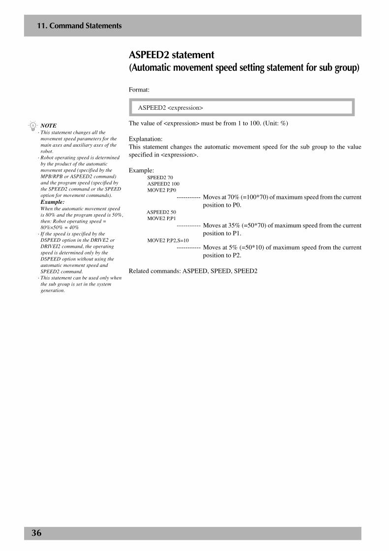
36
2
11. Command Statements
ASPEED2 statement(Automatic movement speed setting statement for sub group)
Format:
ASPEED2 <expression>
The value of <expression> must be from 1 to 100. (Unit: %)
Explanation:This statement changes the automatic movement speed for the sub group to the valuespecified in <expression>.
Example:SPEED2 70ASPEED2 100MOVE2 P,P0
----------- Moves at 70% (=100*70) of maximum speed from the currentposition to P0.
ASPEED2 50MOVE2 P,P1
----------- Moves at 35% (=50*70) of maximum speed from the currentposition to P1.
MOVE2 P,P2,S=10
----------- Moves at 5% (=50*10) of maximum speed from the currentposition to P2.
Related commands: ASPEED, SPEED, SPEED2
n NOTE· This statement changes all the
movement speed parameters for themain axes and auxiliary axes of therobot.
· Robot operating speed is determinedby the product of the automaticmovement speed (specified by theMPB/RPB or ASPEED2 command)and the program speed (specified bythe SPEED2 command or the SPEEDoption for movement commands).Example:When the automatic movement speedis 80% and the program speed is 50%,then: Robot operating speed =80%×50% = 40%
· If the speed is specified by theDSPEED option in the DRIVE2 orDRIVEI2 command, the operatingspeed is determined only by theDSPEED option without using theautomatic movement speed andSPEED2 command.
· This statement can be used only whenthe sub group is set in the systemgeneration.
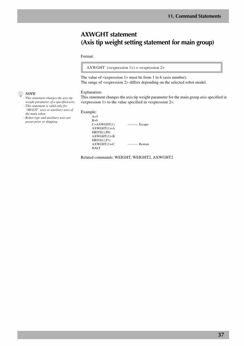
37
2
11. Command Statements
AXWGHT statement(Axis tip weight setting statement for main group)
Format:
AXWGHT (<expression 1>) = <expression 2>
The value of <expression 1> must be from 1 to 6 (axis number).The range of <expression 2> differs depending on the selected robot model.
Explanation:This statement changes the axis tip weight parameter for the main group axis specified in<expression 1> to the value specified in <expression 2>.
Example:A=5B=0C=AXWGHT(1) --------- EscapeAXWGHT(1)=ADRIVE(1,P0)AXWGHT(1)=BDRIVE(1,P1)AXWGHT(1)=C --------- RestoreHALT
Related commands: WEIGHT, WEIGHT2, AXWGHT2
n NOTE· This statement changes the axis tip
weight parameter of a specified axis.· This statement is valid only for
“MULTI” axes or auxiliary axes ofthe main robot.
· Robot type and auxiliary axes arepreset prior to shipping.
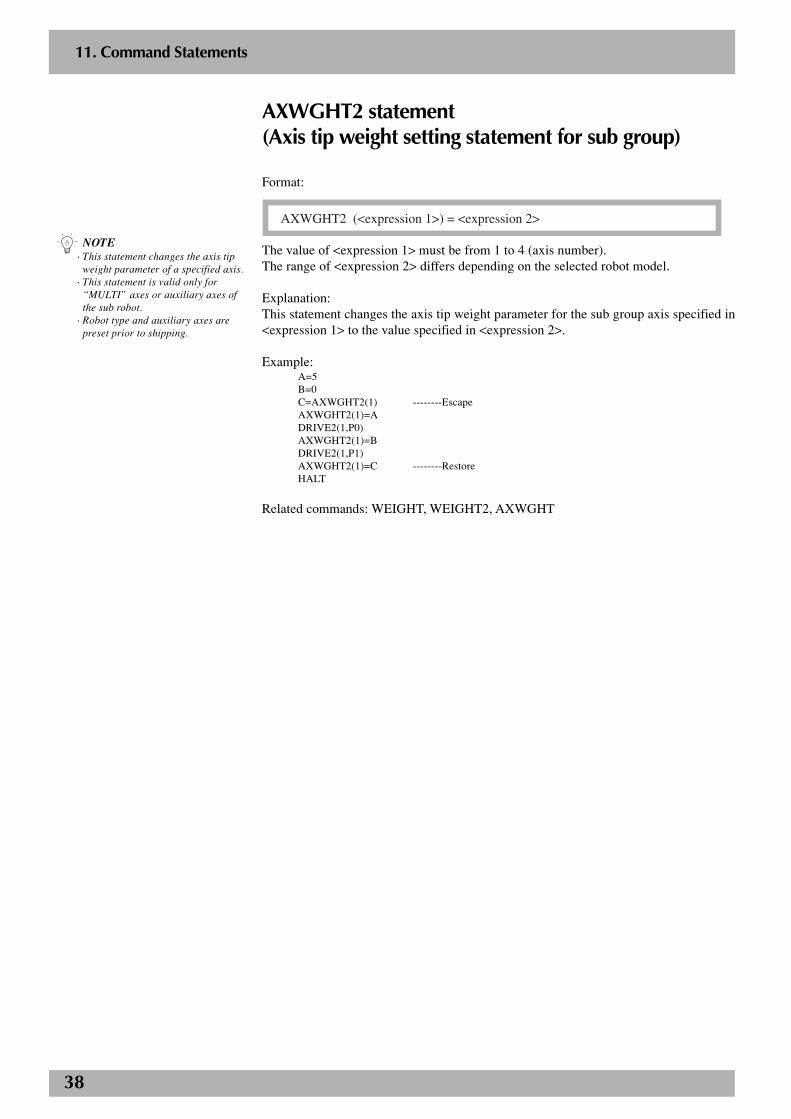
38
2
11. Command Statements
AXWGHT2 statement(Axis tip weight setting statement for sub group)
Format:
AXWGHT2 (<expression 1>) = <expression 2>
The value of <expression 1> must be from 1 to 4 (axis number).The range of <expression 2> differs depending on the selected robot model.
Explanation:This statement changes the axis tip weight parameter for the sub group axis specified in<expression 1> to the value specified in <expression 2>.
Example:A=5B=0C=AXWGHT2(1) --------EscapeAXWGHT2(1)=ADRIVE2(1,P0)AXWGHT2(1)=BDRIVE2(1,P1)AXWGHT2(1)=C --------RestoreHALT
Related commands: WEIGHT, WEIGHT2, AXWGHT
n NOTE· This statement changes the axis tip
weight parameter of a specified axis.· This statement is valid only for
“MULTI” axes or auxiliary axes ofthe sub robot.
· Robot type and auxiliary axes arepreset prior to shipping.
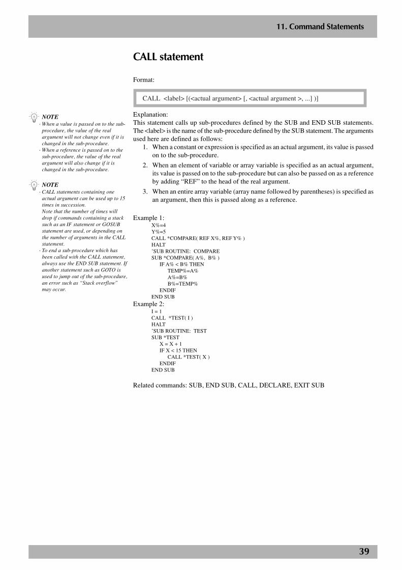
39
2
11. Command Statements
CALL statement
Format:
CALL <label> [(<actual argument> [, <actual argument >, ...] )]
Explanation:This statement calls up sub-procedures defined by the SUB and END SUB statements.The <label> is the name of the sub-procedure defined by the SUB statement. The argumentsused here are defined as follows:
1. When a constant or expression is specified as an actual argument, its value is passedon to the sub-procedure.
2. When an element of variable or array variable is specified as an actual argument,its value is passed on to the sub-procedure but can also be passed on as a referenceby adding “REF” to the head of the real argument.
3. When an entire array variable (array name followed by parentheses) is specified asan argument, then this is passed along as a reference.
Example 1:X%=4Y%=5CALL *COMPARE( REF X%, REF Y% )HALT’SUB ROUTINE: COMPARESUB *COMPARE( A%, B% )
IF A% < B% THENTEMP%=A%A%=B%B%=TEMP%
ENDIFEND SUB
Example 2:I = 1CALL *TEST( I )HALT’SUB ROUTINE: TESTSUB *TEST
X = X + 1IF X < 15 THEN
CALL *TEST( X )ENDIF
END SUB
Related commands: SUB, END SUB, CALL, DECLARE, EXIT SUB
n NOTE· When a value is passed on to the sub-
procedure, the value of the realargument will not change even if it ischanged in the sub-procedure.
· When a reference is passed on to thesub-procedure, the value of the realargument will also change if it ischanged in the sub-procedure.
n NOTE· CALL statements containing one
actual argument can be used up to 15times in succession.Note that the number of times willdrop if commands containing a stacksuch as an IF statement or GOSUBstatement are used, or depending onthe number of arguments in the CALLstatement.
· To end a sub-procedure which hasbeen called with the CALL statement,always use the END SUB statement. Ifanother statement such as GOTO isused to jump out of the sub-procedure,an error such as “Stack overflow”may occur.
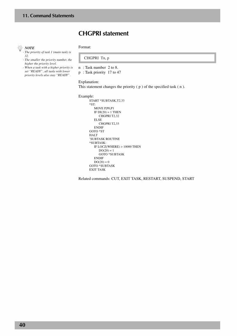
40
2
11. Command Statements
CHGPRI statement
Format:
CHGPRI Tn, p
n : Task number 2 to 8.p : Task priority 17 to 47
Explanation:This statement changes the priority ( p ) of the specified task ( n ).
Example:START *SUBTASK,T2,33*ST:
MOVE P,P0,P1IF DI(20) = 1 THEN
CHGPRI T2,32ELSE
CHGPRI T2,33ENDIF
GOTO *STHALT’SUBTASK ROUTINE*SUBTASK:
IF LOCZ(WHERE) > 10000 THENDO(20) = 1GOTO *SUBTASK
ENDIFDO(20) = 0
GOTO *SUBTASKEXIT TASK
Related commands: CUT, EXIT TASK, RESTART, SUSPEND, START
n NOTE· The priority of task 1 (main task) is
32.· The smaller the priority number, the
higher the priority level.· When a task with a higher priority is
set “READY”, all tasks with lowerpriority levels also stay “READY”.
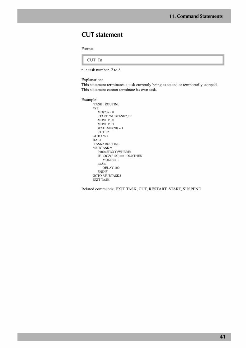
41
2
11. Command Statements
CUT statement
Format:
CUT Tn
n : task number 2 to 8
Explanation:This statement terminates a task currently being executed or temporarily stopped.This statement cannot terminate its own task.
Example:’TASK1 ROUTINE*ST:
MO(20) = 0START *SUBTASK2,T2MOVE P,P0MOVE P,P1WAIT MO(20) = 1CUT T2
GOTO *STHALT’TASK2 ROUTINE*SUBTASK2:
P100=JTOXY(WHERE)IF LOCZ(P100) >= 100.0 THEN
MO(20) = 1ELSE
DELAY 100ENDIF
GOTO *SUBTASK2EXIT TASK
Related commands: EXIT TASK, CUT, RESTART, START, SUSPEND

42
2
11. Command Statements
DECEL statement(Deceleration setting statement for main group)Format 1:
DECEL <expression>
Format 2:
DECEL (<expression 1>) = <expression 2>
The value of <expression 1> must be from 1 to 6 (axis number).The value of <expression> and <expression 2> must be from 1 to 100. (Unit: %)
Explanation:This statement changes the deceleration rate of the main group parameter to the valuespecified in <expression>.Format 1 changes all axes in the main group. Format 2 changes the deceleration rate ofthe axis specified in <expression 1> to the value specified in <expression 2>.
Example:A =50DECEL ADECEL(3)=100'CYCLE WITH INCREASING DECELERATIONFOR A =10 TO 100 STEP 10 DECEL A MOVE P ,P0 MOVE P ,P1NEXT AHALT "END TEST"
n NOTE• The deceleration set in the axis
parameters for the robotconfiguration axis and auxiliary axisis changed.
• If an axis that is set to "no axis" in thesystem generation is specified, then anerror message "Specificationmismatch" appears and execution ofthe command will stop.
c CAUTIONThe DECEL statement is onlyavailable from software version 8.15onwards.
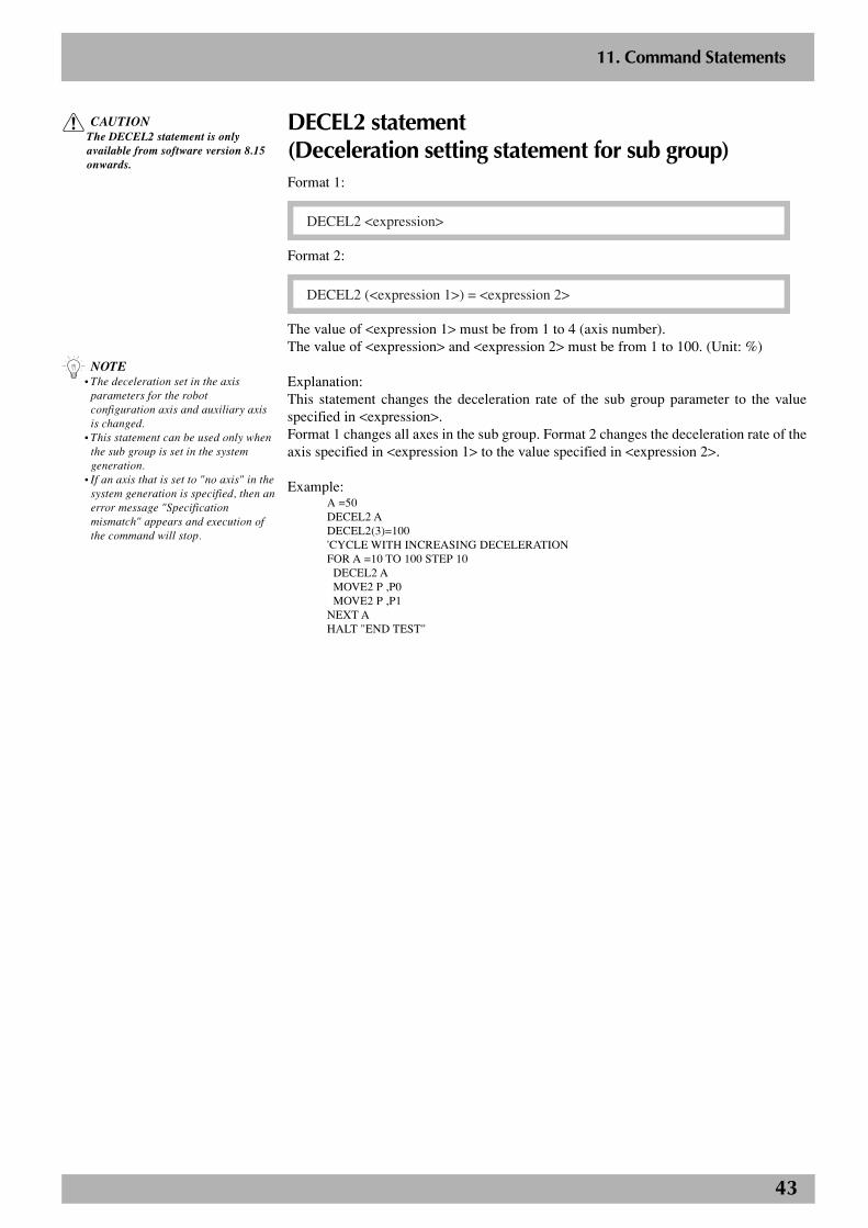
43
2
11. Command Statements
DECEL2 statement(Deceleration setting statement for sub group)Format 1:
DECEL2 <expression>
Format 2:
DECEL2 (<expression 1>) = <expression 2>
The value of <expression 1> must be from 1 to 4 (axis number).The value of <expression> and <expression 2> must be from 1 to 100. (Unit: %)
Explanation:This statement changes the deceleration rate of the sub group parameter to the valuespecified in <expression>.Format 1 changes all axes in the sub group. Format 2 changes the deceleration rate of theaxis specified in <expression 1> to the value specified in <expression 2>.
Example:A =50DECEL2 ADECEL2(3)=100'CYCLE WITH INCREASING DECELERATIONFOR A =10 TO 100 STEP 10 DECEL2 A MOVE2 P ,P0 MOVE2 P ,P1NEXT AHALT "END TEST"
n NOTE• The deceleration set in the axis
parameters for the robotconfiguration axis and auxiliary axisis changed.
• This statement can be used only whenthe sub group is set in the systemgeneration.
• If an axis that is set to "no axis" in thesystem generation is specified, then anerror message "Specificationmismatch" appears and execution ofthe command will stop.
c CAUTIONThe DECEL2 statement is onlyavailable from software version 8.15onwards.

44
2
11. Command Statements
n NOTE· External programs can only use
“COMMON”.· Only the GOSUB, CALL, ON ~
GOSUB statements can use externallabels.
DECLARE statement
Format 1:
DECLARE <label> [, <label>...]
<label>: Label defined by an external program.
Format 2:
DECLARE SUB <label> [(<dummy argument> [, <dummy argument>]...) ]
<label> : Name of sub-procedure defined by an external program.
<dummy argument> : Argument for sub-procedure. This format is significant only forthe number of arguments and data type.
Explanation:This statement declares that a label or sub-procedure is in an external program. In thecase of a sub-procedure, the data type of the argument is also checked.The DECLARE statement can be written in programs other than the COMMON program(but cannot be defined in a sub-procedure) and is effective over the entire program.
Example:Labels shared with an external program.Program name: DIST1’===============================’ MAIN PROGRAM’===============================
DECLARE *DISTANCE,*AREAX!=2.5Y!=1.2GOSUB *DISTANCEGOSUB *AREAHALT
Program name: COMMON’===============================’ ’COMMON’PROGRAM’===============================
*DISTANCE:PRINT X!^2+Y!^2RETURN
*AREA:PRINT X!*Y!RETURN

45
2
11. Command Statements
Example:Sub-procedures shared with an external programProgram name: DIST2’===========================’ MAIN PROGRAM’===========================
DECLARE SUB *DISTANCE(X!,Y!,D!)DECLARE SUB *AREA(X!,Y!,A!)CALL *DISTANCE(2.5,1.2,REF D!)PRINT D!CALL *AREA(2.5,1.2,REF A!)PRINT A!HALT
Program name: COMMON’===========================’ ’COMMON’ PROGRAM’===========================
SUB *DISTANCE(X!,Y!,D!)D!=X!^2+Y!^2END SUBSUB *AREA(X!,Y!,A!)A!=X!*Y!END SUB
Related commands: CALL, EXIT SUB, GOSUB, ON~GOSUB, SUB, END SUB
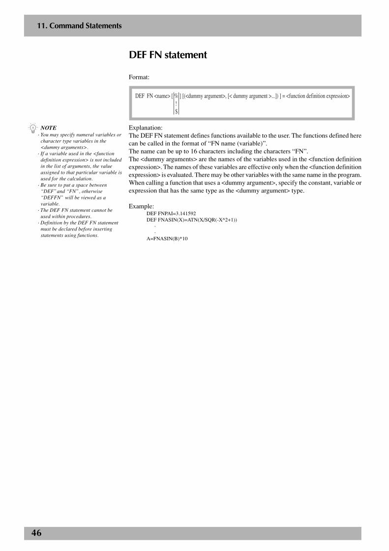
46
2
11. Command Statements
DEF FN statement
Format:
DEF FN <name> [ % ] [(<dummy argument>, [< dummy argument >...]) ] = <function definition expression> ! $
Explanation:The DEF FN statement defines functions available to the user. The functions defined herecan be called in the format of “FN name (variable)”.The name can be up to 16 characters including the characters “FN”.The <dummy arguments> are the names of the variables used in the <function definitionexpression>. The names of these variables are effective only when the <function definitionexpression> is evaluated. There may be other variables with the same name in the program.When calling a function that uses a <dummy argument>, specify the constant, variable orexpression that has the same type as the <dummy argument> type.
Example:DEF FNPAI=3.141592DEF FNASIN(X)=ATN(X/SQR(-X^2+1))
··
A=FNASIN(B)*10
n NOTE· You may specify numeral variables or
character type variables in the<dummy arguments>.
· If a variable used in the <functiondefinition expression> is not includedin the list of arguments, the valueassigned to that particular variable isused for the calculation.
· Be sure to put a space between“DEF”and “FN”, otherwise“DEFFN” will be viewed as avariable.
· The DEF FN statement cannot beused within procedures.
· Definition by the DEF FN statementmust be declared before insertingstatements using functions.
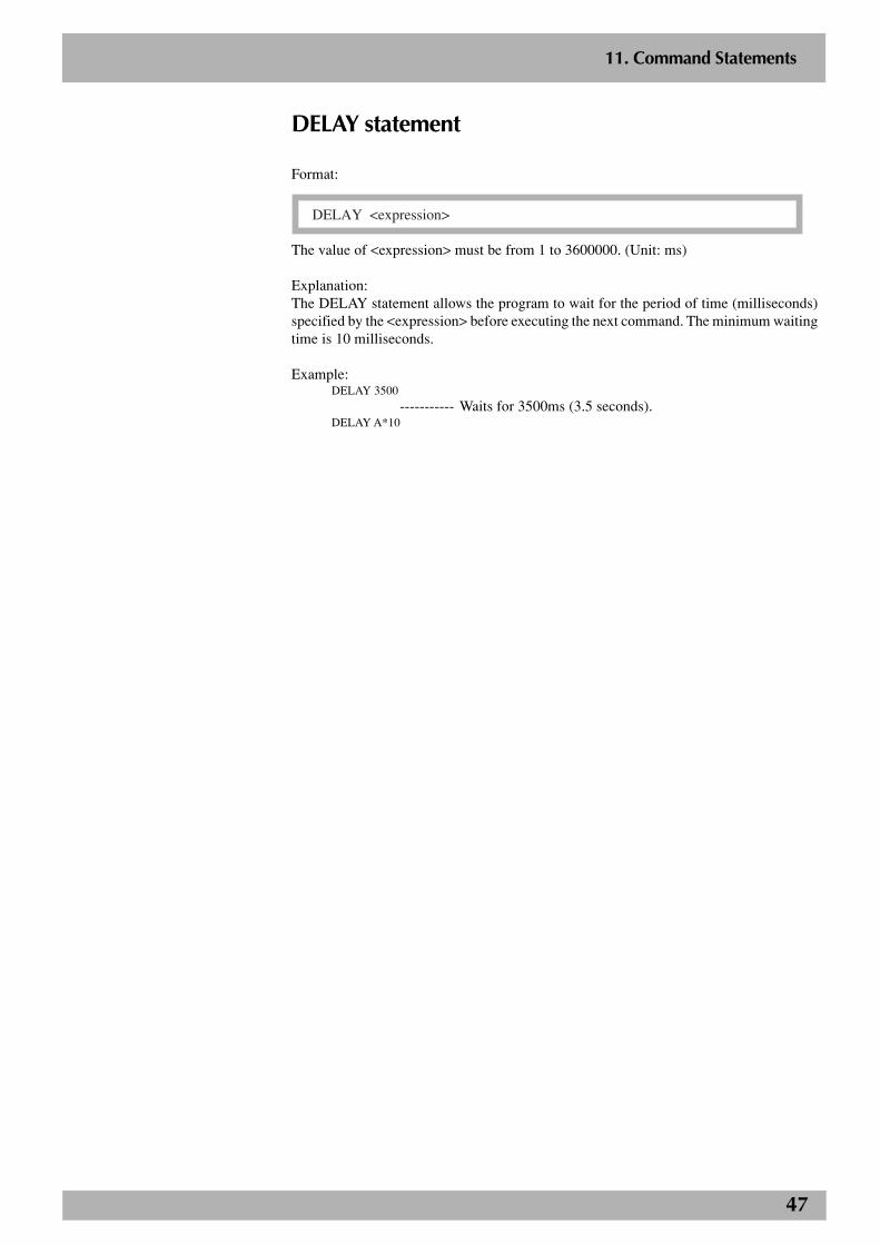
47
2
11. Command Statements
DELAY statement
Format:
DELAY <expression>
The value of <expression> must be from 1 to 3600000. (Unit: ms)
Explanation:The DELAY statement allows the program to wait for the period of time (milliseconds)specified by the <expression> before executing the next command. The minimum waitingtime is 10 milliseconds.
Example:DELAY 3500
----------- Waits for 3500ms (3.5 seconds).DELAY A*10
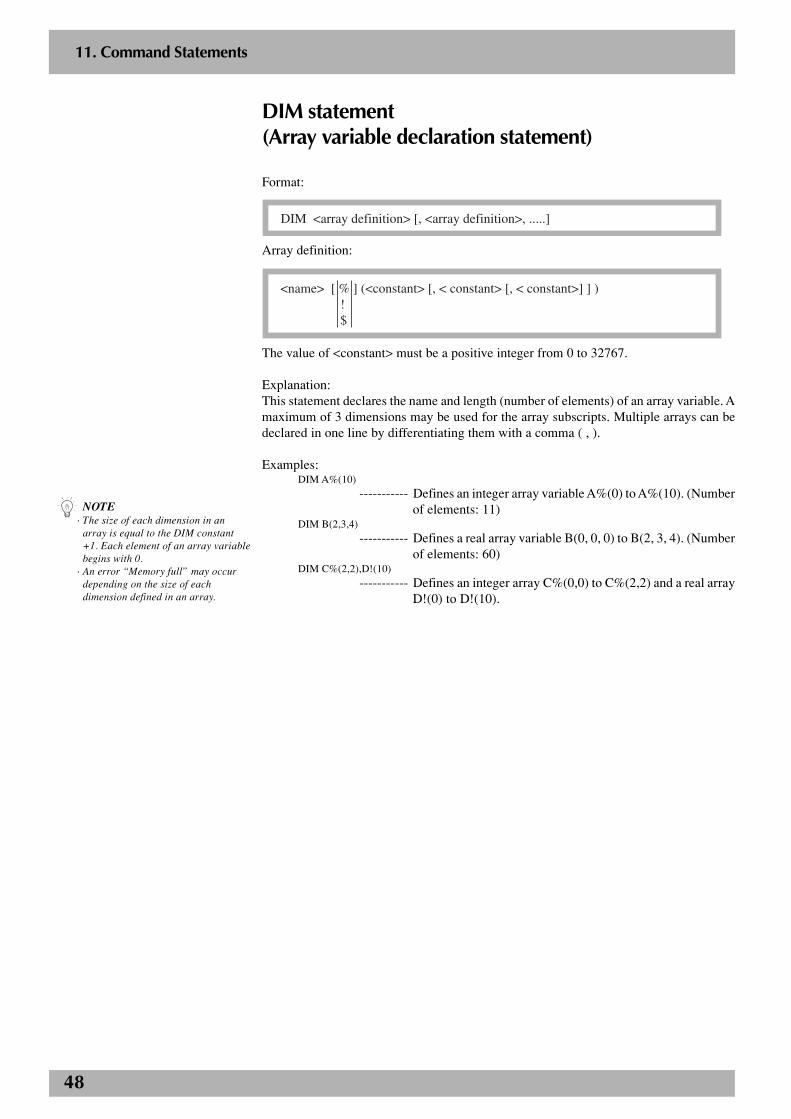
48
2
11. Command Statements
DIM statement(Array variable declaration statement)
Format:
DIM <array definition> [, <array definition>, .....]
Array definition:
<name> [ % ] (<constant> [, < constant> [, < constant>] ] ) ! $
The value of <constant> must be a positive integer from 0 to 32767.
Explanation:This statement declares the name and length (number of elements) of an array variable. Amaximum of 3 dimensions may be used for the array subscripts. Multiple arrays can bedeclared in one line by differentiating them with a comma ( , ).
Examples:DIM A%(10)
----------- Defines an integer array variable A%(0) to A%(10). (Numberof elements: 11)
DIM B(2,3,4)
----------- Defines a real array variable B(0, 0, 0) to B(2, 3, 4). (Numberof elements: 60)
DIM C%(2,2),D!(10)
----------- Defines an integer array C%(0,0) to C%(2,2) and a real arrayD!(0) to D!(10).
n NOTE· The size of each dimension in an
array is equal to the DIM constant+1. Each element of an array variablebegins with 0.
· An error “Memory full” may occurdepending on the size of eachdimension defined in an array.
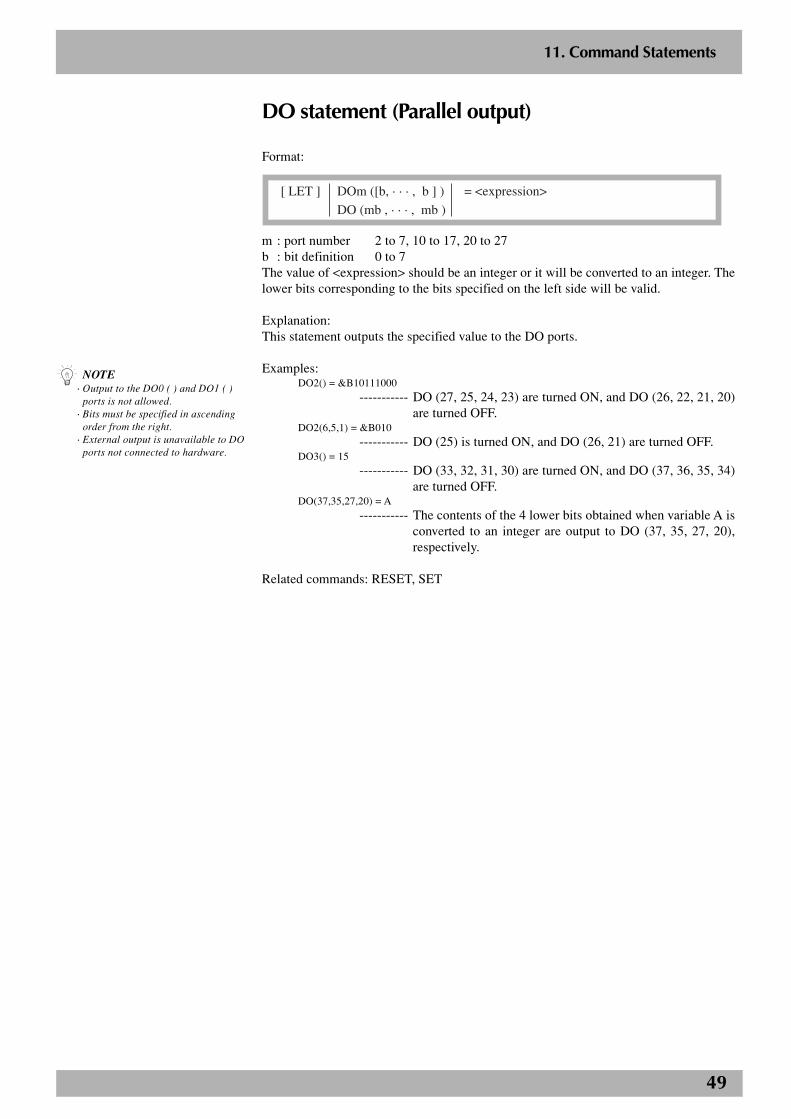
49
2
11. Command Statements
DO statement (Parallel output)
Format:
[ LET ] DOm ([b, · · · , b ] ) = <expression>
DO (mb , · · · , mb )
m : port number 2 to 7, 10 to 17, 20 to 27b : bit definition 0 to 7The value of <expression> should be an integer or it will be converted to an integer. Thelower bits corresponding to the bits specified on the left side will be valid.
Explanation:This statement outputs the specified value to the DO ports.
Examples:DO2() = &B10111000
----------- DO (27, 25, 24, 23) are turned ON, and DO (26, 22, 21, 20)are turned OFF.
DO2(6,5,1) = &B010
----------- DO (25) is turned ON, and DO (26, 21) are turned OFF.DO3() = 15
----------- DO (33, 32, 31, 30) are turned ON, and DO (37, 36, 35, 34)are turned OFF.
DO(37,35,27,20) = A
----------- The contents of the 4 lower bits obtained when variable A isconverted to an integer are output to DO (37, 35, 27, 20),respectively.
Related commands: RESET, SET
n NOTE· Output to the DO0 ( ) and DO1 ( )
ports is not allowed.· Bits must be specified in ascending
order from the right.· External output is unavailable to DO
ports not connected to hardware.
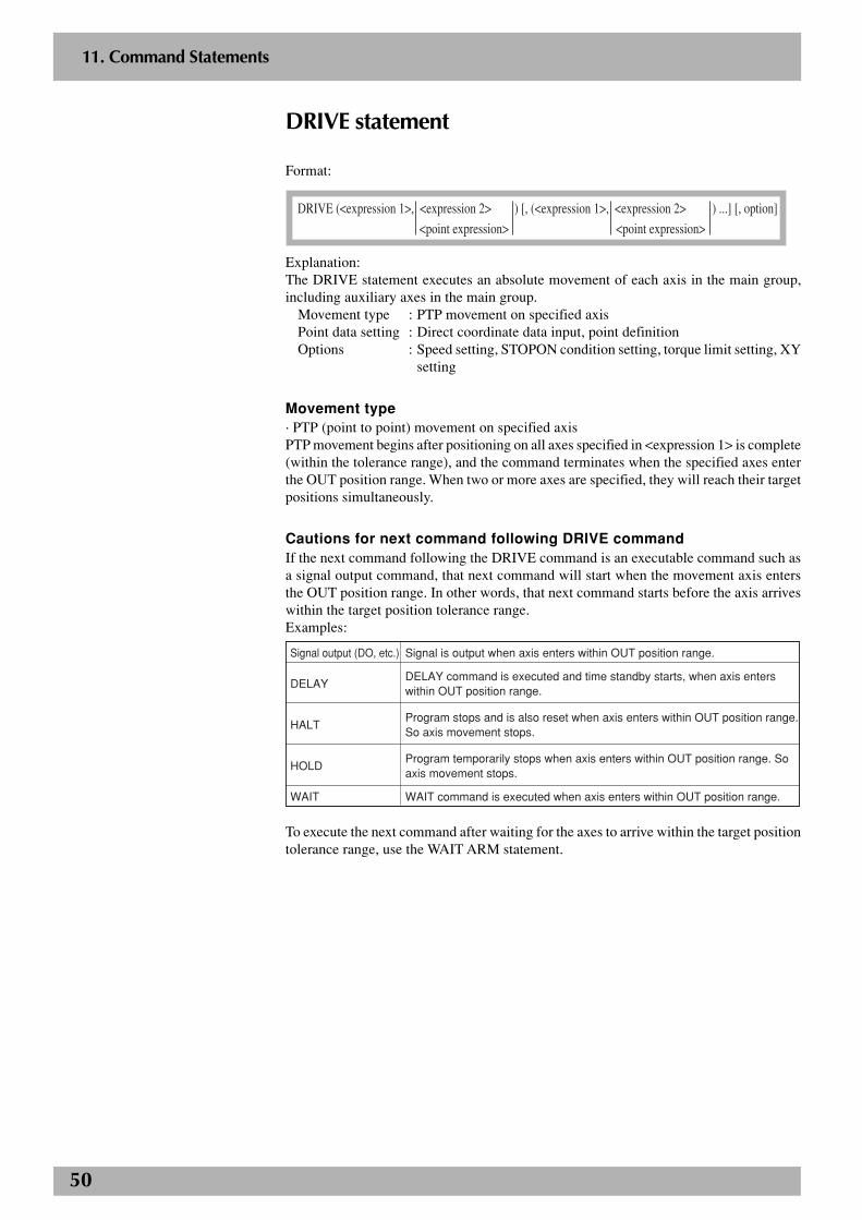
50
2
11. Command Statements
DRIVE statement
Format:
DRIVE (<expression 1>, <expression 2> ) [, (<expression 1>, <expression 2> ) ...] [, option]
<point expression> <point expression>
Explanation:The DRIVE statement executes an absolute movement of each axis in the main group,including auxiliary axes in the main group.
Movement type : PTP movement on specified axisPoint data setting : Direct coordinate data input, point definitionOptions : Speed setting, STOPON condition setting, torque limit setting, XY
setting
Movement type· PTP (point to point) movement on specified axisPTP movement begins after positioning on all axes specified in <expression 1> is complete(within the tolerance range), and the command terminates when the specified axes enterthe OUT position range. When two or more axes are specified, they will reach their targetpositions simultaneously.
Cautions for next command following DRIVE commandIf the next command following the DRIVE command is an executable command such asa signal output command, that next command will start when the movement axis entersthe OUT position range. In other words, that next command starts before the axis arriveswithin the target position tolerance range.Examples:
Signal output (DO, etc.)
DELAY
HALT
HOLD
WAIT
Signal is output when axis enters within OUT position range.
DELAY command is executed and time standby starts, when axis enters within OUT position range.
Program stops and is also reset when axis enters within OUT position range. So axis movement stops.
Program temporarily stops when axis enters within OUT position range. So axis movement stops.
WAIT command is executed when axis enters within OUT position range.
To execute the next command after waiting for the axes to arrive within the target positiontolerance range, use the WAIT ARM statement.
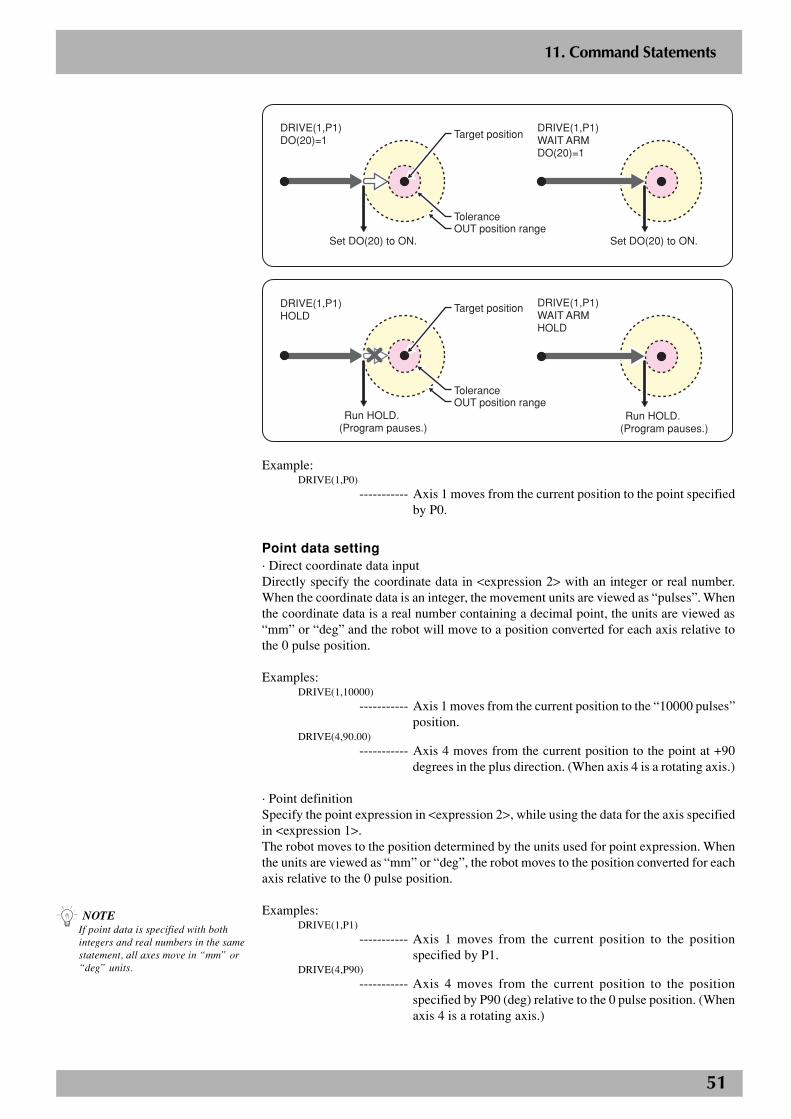
51
2
11. Command Statements
P1
Set DO(20) to ON.
DRIVE(1,P1)WAIT ARMDO(20)=1
Set DO(20) to ON.
DRIVE(1,P1)DO(20)=1
Tolerance
Target position
OUT position range
Run HOLD.(Program pauses.)
DRIVE(1,P1)WAIT ARMHOLD
DRIVE(1,P1)HOLD
ToleranceOUT position range
Target position
Run HOLD.(Program pauses.)
Example:DRIVE(1,P0)
----------- Axis 1 moves from the current position to the point specifiedby P0.
Point data setting· Direct coordinate data inputDirectly specify the coordinate data in <expression 2> with an integer or real number.When the coordinate data is an integer, the movement units are viewed as “pulses”. Whenthe coordinate data is a real number containing a decimal point, the units are viewed as“mm” or “deg” and the robot will move to a position converted for each axis relative tothe 0 pulse position.
Examples:DRIVE(1,10000)
----------- Axis 1 moves from the current position to the “10000 pulses”position.
DRIVE(4,90.00)
----------- Axis 4 moves from the current position to the point at +90degrees in the plus direction. (When axis 4 is a rotating axis.)
· Point definitionSpecify the point expression in <expression 2>, while using the data for the axis specifiedin <expression 1>.The robot moves to the position determined by the units used for point expression. Whenthe units are viewed as “mm” or “deg”, the robot moves to the position converted for eachaxis relative to the 0 pulse position.
Examples:DRIVE(1,P1)
----------- Axis 1 moves from the current position to the positionspecified by P1.
DRIVE(4,P90)----------- Axis 4 moves from the current position to the position
specified by P90 (deg) relative to the 0 pulse position. (Whenaxis 4 is a rotating axis.)
n NOTEIf point data is specified with bothintegers and real numbers in the samestatement, all axes move in “mm” or“deg” units.
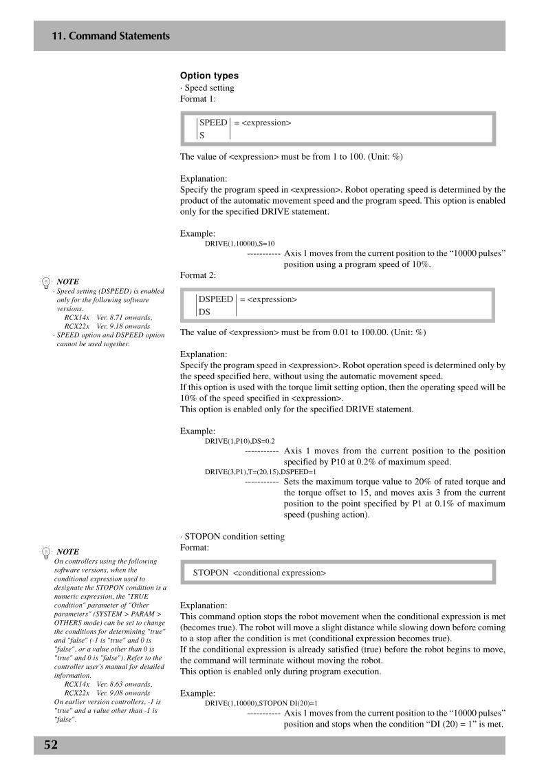
52
2
11. Command Statements
Option types· Speed settingFormat 1:
SPEED = <expression>
S
The value of <expression> must be from 1 to 100. (Unit: %)
Explanation:Specify the program speed in <expression>. Robot operating speed is determined by theproduct of the automatic movement speed and the program speed. This option is enabledonly for the specified DRIVE statement.
Example:DRIVE(1,10000),S=10
----------- Axis 1 moves from the current position to the “10000 pulses”position using a program speed of 10%.
Format 2:
DSPEED = <expression>
DS
The value of <expression> must be from 0.01 to 100.00. (Unit: %)
Explanation:Specify the program speed in <expression>. Robot operation speed is determined only bythe speed specified here, without using the automatic movement speed.If this option is used with the torque limit setting option, then the operating speed will be10% of the speed specified in <expression>.This option is enabled only for the specified DRIVE statement.
Example:DRIVE(1,P10),DS=0.2
----------- Axis 1 moves from the current position to the positionspecified by P10 at 0.2% of maximum speed.
DRIVE(3,P1),T=(20,15),DSPEED=1----------- Sets the maximum torque value to 20% of rated torque and
the torque offset to 15, and moves axis 3 from the currentposition to the point specified by P1 at 0.1% of maximumspeed (pushing action).
· STOPON condition settingFormat:
STOPON <conditional expression>
Explanation:This command option stops the robot movement when the conditional expression is met(becomes true). The robot will move a slight distance while slowing down before comingto a stop after the condition is met (conditional expression becomes true).If the conditional expression is already satisfied (true) before the robot begins to move,the command will terminate without moving the robot.This option is enabled only during program execution.
Example:DRIVE(1,10000),STOPON DI(20)=1
----------- Axis 1 moves from the current position to the “10000 pulses”position and stops when the condition “DI (20) = 1” is met.
n NOTEOn controllers using the followingsoftware versions, when theconditional expression used todesignate the STOPON condition is anumeric expression, the "TRUEcondition" parameter of "Otherparameters" (SYSTEM > PARAM >OTHERS mode) can be set to changethe conditions for determining "true"and "false" (-1 is "true" and 0 is"false", or a value other than 0 is"true" and 0 is "false"). Refer to thecontroller user's manual for detailedinformation.
RCX14x Ver. 8.63 onwards,RCX22x Ver. 9.08 onwards
On earlier version controllers, -1 is"true" and a value other than -1 is"false".
n NOTE· Speed setting (DSPEED) is enabled
only for the following softwareversions.
RCX14x Ver. 8.71 onwards,RCX22x Ver. 9.18 onwards
· SPEED option and DSPEED optioncannot be used together.
53
2
11. Command Statements
· Torque limit settingFormat 1:
T = <expression 1>
Format 2:
T = (<expression 1> [,<expression 2>] )
The value of <expression 1> is the torque limit specified in percent of rated torque andmust be from 1 to 100. (Unit: %)The value of <expression 2> is the torque offset and must be from -100 to 100.
Explanation:Moves the axis while under torque control.The maximum torque at this point is limited to a value calculated from: Rated torque ×<expression 1> / 100.The value of <expression 2> determines the torque offset. Specify this offset when con-trolling the torque on an axis such as a vertical axis to which a fixed load is constantlyapplied. Torque offset value is set to 0 if <expression 2> is omitted and in Format 1.The torque offset specified in <expression 2> is the torque command value (maximumtorque ratio) constantly generated on the axis. Display it on the current command monitorwhile the axis is stopped with the servo turned on, and specify the torque value displayedat that point.
When the DRIVE statement is executed with this option specified, the robot moves to thetarget position while controlling the torque by changing the maximum torque on the axisto a value specified in <expression 1>. The movement speed at this point is limited to amaximum of 10% of normal operating speed. No errors will occur even if the robot con-tacts an obstacle during movement and the axis torque (thrust) will not exceed the limitvalue.
This command ends when the axis has reached the target position or when the time (time-out period) specified by the TRQTIME statement has elapsed while the axis torque (thrust)has reached the limit value. When this command has ended due to a time-out duringwhich the axis torque has reached its limit value, then 1 is set in the TRQSTS function.
The maximum torque limit and torque control condition continues even after this com-mand has ended. This is the same in cases where the robot is stopped such as by aninterlock while executing this command.Torque control is released by an axis operation such as switching servo on/off switchingor executing the MOVE command. To release the maximum torque limit, set a new maxi-mum torque instruction by using the TORQUE statement. Note, however, that the maxi-mum torque instruction is not enabled immediately. It will be enabled after the next move-ment command such as a MOVE or DRIVE statement is executed.The maximum torque limit is released in the following cases, regardless of whether theTORQUE statement is executed or not.
• When controller power is turned on.
• When servo is turned off.
• When return-to-origin or absolute reset (except for mark method) is performed.
• When parameters are changed or initialized.
The following restrictions apply when specifying this option.• Two or more axes cannot be specified with this option.
• Maximum movement speed is set to 10% of normal operating speed.
• Manual movement is not possible under torque control after this command wasexecuted.
c CAUTION· Conditions for ending this command
(mentioned on the right) are onlyvalid from software version 8.45onwards. On earlier versioncontrollers, this command ends inthe following cases.· The axis has reached the target
position at the point when the timerequired to move to the targetposition has elapsed.
· The axis torque has already reachedthe limit value for more than 1second at the point when the timerequired to move to the targetposition has elapsed.
· The torque has reached the limitvalue at the point when the timerequired to move to the targetposition has elapsed, and thiscondition has continued for 1second.
· The timing that enables a maximumtorque instruction changed by theTORQUE statement (mentioned onthe right) is only valid from driverversion 2.17 onwards. On earlierversion controllers, the maximumtorque instruction is enabled at thepoint when it was changed by theTORQUE statement.
c CAUTION· The torque offset setting is only
available from software version 8.18onwards.
· The torque limit setting range differsdepending on the robot model.Setting a torque limit higher than themaximum level may cause robotmalfunctions or breakdowns.
· If the specified torque limit is toosmall, the axis might not move.
n NOTEFor details on the current commandmonitor, refer to "13. Monitor mode"in Chapter 4 of the user's manual foreach controller.
54
2
11. Command Statements
Example:TRQTIME(3)=2500
----------- Sets the torque control time-out period on axis 3 to 2.5 sec-onds.
DRIVE(3,P1),T=(20,15)
----------- Sets the maximum torque value to 20% of rated torque andthe torque offset to 15, and moves axis 3 from the currentposition to the point specified by P1 (pushing action).
IF TRQSTS(3)=1 THEN
----------- Checks if time-out is up.DO(21)=1
----------- Time-out is up (pushing is complete).(Result is output to DO(21) in this example.)
ELSEDO(21)=0
----------- Time-out is not yet up. (Reached target position but failed tocomplete pushing.)(Result is output to DO(21) in this example.)
ENDIFTORQUE(3)=100
----------- Returns the maximum torque instruction to original value(100%).
DRIVE(3,P0)
----------- Ends the torque limit and torque control, and moves to P0.
Related commands: TORQUE, TRQTIME, TRQSTS functions
· XY settingFormat:
XY
Explanation:This option moves the specified multiple axes to the position specified on the XY coordi-nates.The following are limitation items when using this command option.
1. Axes specified in <expression 1> must include axes 1 and 2.
2. Robots that can be specified with this option are SCARA robots and Cartesianrobots.
3. Point setting must be in “mm” or “deg” units (real number setting).
Examples: DRIVE(1,P100),(2,P100),(4,P100),XY
----------- Axes 1, 2 and 4 move from the current position to the posi-tion on the XY coordinates specified by P100.

55
2
11. Command Statements
DRIVE2 statement
Format:
DRIVE2 (<expression 1>, <expression 2> ) [, (<expression 1>, <expression 2> ) ...] [, option]
<point expression> <point expression>
Explanation:The DRIVE2 statement executes an absolute movement of each axis in the sub group,including auxiliary axes in the sub group.
Movement type : PTP movement on specified axisPoint data setting : Direct coordinate data input, point definitionOptions : Speed setting, STOPON condition setting, torque limit setting, XY
setting
Movement type· PTP (point to point) movement on specified axisPTP movement begins after positioning on all axes specified in <expression 1> is complete(within the tolerance range), and the command terminates when the specified axes enterthe OUT position range. When two or more axes are specified, they will reach their targetpositions simultaneously.
Cautions for next command following DRIVE2 commandIf the next command following the DRIVE2 command is an executable command such asa signal output command, that next command will start when the movement axis entersthe OUT position range. In other words, that next command starts before the axis arriveswithin the target position tolerance range.Examples:
Signal output (DO, etc.)
DELAY
HALT
HOLD
WAIT
Signal is output when axis enters within OUT position range.
DELAY command is executed and time standby starts, when axis enters within OUT position range.
Program stops and is also reset when axis enters within OUT position range. So axis movement stops.
Program temporarily stops when axis enters within OUT position range. So axis movement stops.
WAIT command is executed when axis enters within OUT position range.
To execute the next command after waiting for the axes to arrive within the target positiontolerance range, use the WAIT ARM2 statement.
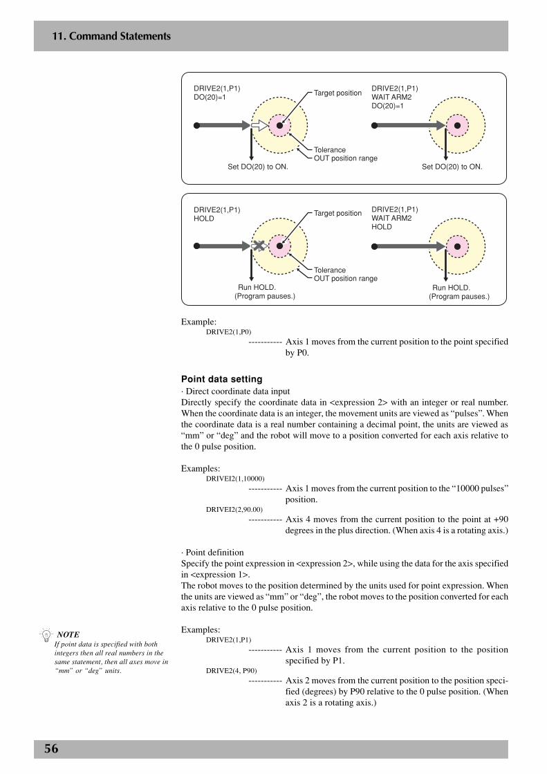
56
2
11. Command Statements
P1
Set DO(20) to ON.
DRIVE2(1,P1)WAIT ARM2DO(20)=1
Set DO(20) to ON.
DRIVE2(1,P1)DO(20)=1
Tolerance
Target position
OUT position range
Run HOLD.(Program pauses.)
DRIVE2(1,P1)WAIT ARM2HOLD
DRIVE2(1,P1)HOLD
ToleranceOUT position range
Target position
Run HOLD.(Program pauses.)
Example:DRIVE2(1,P0)
----------- Axis 1 moves from the current position to the point specifiedby P0.
Point data setting· Direct coordinate data inputDirectly specify the coordinate data in <expression 2> with an integer or real number.When the coordinate data is an integer, the movement units are viewed as “pulses”. Whenthe coordinate data is a real number containing a decimal point, the units are viewed as“mm” or “deg” and the robot will move to a position converted for each axis relative tothe 0 pulse position.
Examples:DRIVEI2(1,10000)
----------- Axis 1 moves from the current position to the “10000 pulses”position.
DRIVEI2(2,90.00)
----------- Axis 4 moves from the current position to the point at +90degrees in the plus direction. (When axis 4 is a rotating axis.)
· Point definitionSpecify the point expression in <expression 2>, while using the data for the axis specifiedin <expression 1>.The robot moves to the position determined by the units used for point expression. Whenthe units are viewed as “mm” or “deg”, the robot moves to the position converted for eachaxis relative to the 0 pulse position.
Examples:DRIVE2(1,P1)
----------- Axis 1 moves from the current position to the positionspecified by P1.
DRIVE2(4, P90)----------- Axis 2 moves from the current position to the position speci-
fied (degrees) by P90 relative to the 0 pulse position. (Whenaxis 2 is a rotating axis.)
n NOTEIf point data is specified with bothintegers then all real numbers in thesame statement, then all axes move in“mm” or “deg” units.
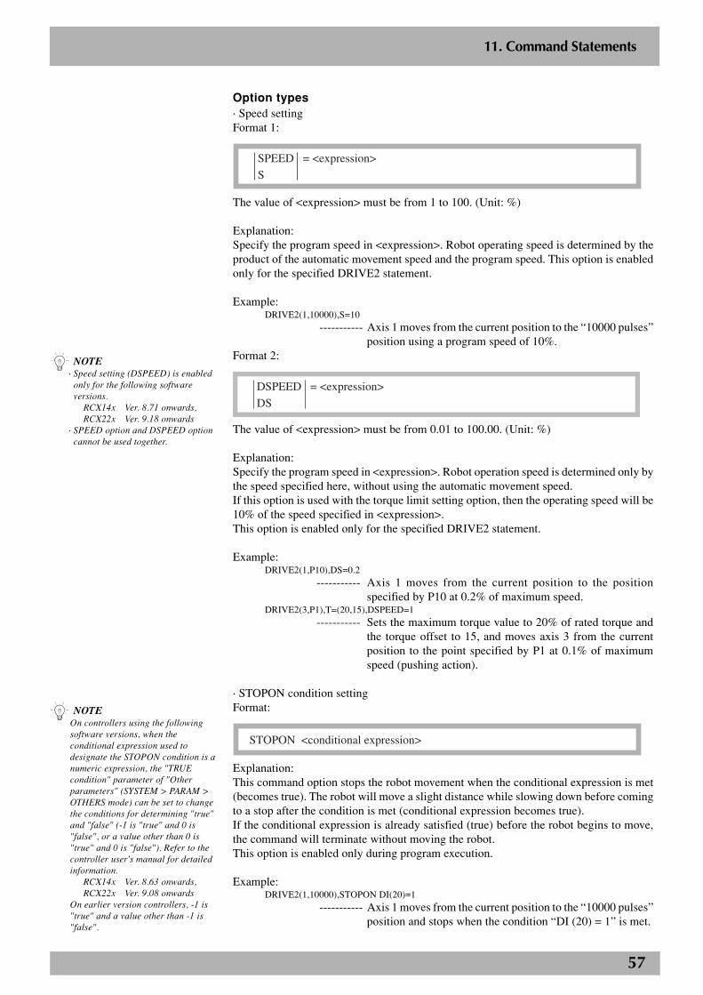
57
2
11. Command Statements
n NOTEOn controllers using the followingsoftware versions, when theconditional expression used todesignate the STOPON condition is anumeric expression, the "TRUEcondition" parameter of "Otherparameters" (SYSTEM > PARAM >OTHERS mode) can be set to changethe conditions for determining "true"and "false" (-1 is "true" and 0 is"false", or a value other than 0 is"true" and 0 is "false"). Refer to thecontroller user's manual for detailedinformation.
RCX14x Ver. 8.63 onwards,RCX22x Ver. 9.08 onwards
On earlier version controllers, -1 is"true" and a value other than -1 is"false".
Option types· Speed settingFormat 1:
SPEED = <expression>
S
The value of <expression> must be from 1 to 100. (Unit: %)
Explanation:Specify the program speed in <expression>. Robot operating speed is determined by theproduct of the automatic movement speed and the program speed. This option is enabledonly for the specified DRIVE2 statement.
Example:DRIVE2(1,10000),S=10
----------- Axis 1 moves from the current position to the “10000 pulses”position using a program speed of 10%.
Format 2:
DSPEED = <expression>
DS
The value of <expression> must be from 0.01 to 100.00. (Unit: %)
Explanation:Specify the program speed in <expression>. Robot operation speed is determined only bythe speed specified here, without using the automatic movement speed.If this option is used with the torque limit setting option, then the operating speed will be10% of the speed specified in <expression>.This option is enabled only for the specified DRIVE2 statement.
Example:DRIVE2(1,P10),DS=0.2
----------- Axis 1 moves from the current position to the positionspecified by P10 at 0.2% of maximum speed.
DRIVE2(3,P1),T=(20,15),DSPEED=1----------- Sets the maximum torque value to 20% of rated torque and
the torque offset to 15, and moves axis 3 from the currentposition to the point specified by P1 at 0.1% of maximumspeed (pushing action).
· STOPON condition settingFormat:
STOPON <conditional expression>
Explanation:This command option stops the robot movement when the conditional expression is met(becomes true). The robot will move a slight distance while slowing down before comingto a stop after the condition is met (conditional expression becomes true).If the conditional expression is already satisfied (true) before the robot begins to move,the command will terminate without moving the robot.This option is enabled only during program execution.
Example:DRIVE2(1,10000),STOPON DI(20)=1
----------- Axis 1 moves from the current position to the “10000 pulses”position and stops when the condition “DI (20) = 1” is met.
n NOTE· Speed setting (DSPEED) is enabled
only for the following softwareversions.
RCX14x Ver. 8.71 onwards,RCX22x Ver. 9.18 onwards
· SPEED option and DSPEED optioncannot be used together.
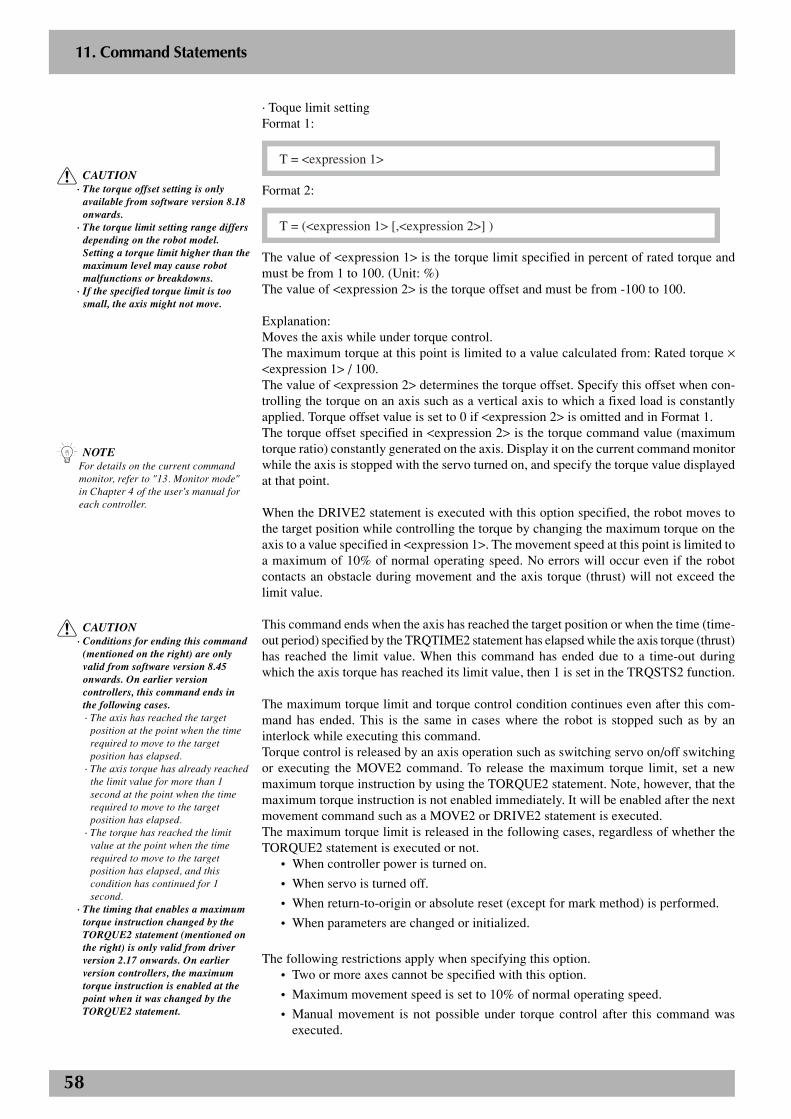
58
2
11. Command Statements
· Toque limit settingFormat 1:
T = <expression 1>
Format 2:
T = (<expression 1> [,<expression 2>] )
The value of <expression 1> is the torque limit specified in percent of rated torque andmust be from 1 to 100. (Unit: %)The value of <expression 2> is the torque offset and must be from -100 to 100.
Explanation:Moves the axis while under torque control.The maximum torque at this point is limited to a value calculated from: Rated torque ×<expression 1> / 100.The value of <expression 2> determines the torque offset. Specify this offset when con-trolling the torque on an axis such as a vertical axis to which a fixed load is constantlyapplied. Torque offset value is set to 0 if <expression 2> is omitted and in Format 1.The torque offset specified in <expression 2> is the torque command value (maximumtorque ratio) constantly generated on the axis. Display it on the current command monitorwhile the axis is stopped with the servo turned on, and specify the torque value displayedat that point.
When the DRIVE2 statement is executed with this option specified, the robot moves tothe target position while controlling the torque by changing the maximum torque on theaxis to a value specified in <expression 1>. The movement speed at this point is limited toa maximum of 10% of normal operating speed. No errors will occur even if the robotcontacts an obstacle during movement and the axis torque (thrust) will not exceed thelimit value.
This command ends when the axis has reached the target position or when the time (time-out period) specified by the TRQTIME2 statement has elapsed while the axis torque (thrust)has reached the limit value. When this command has ended due to a time-out duringwhich the axis torque has reached its limit value, then 1 is set in the TRQSTS2 function.
The maximum torque limit and torque control condition continues even after this com-mand has ended. This is the same in cases where the robot is stopped such as by aninterlock while executing this command.Torque control is released by an axis operation such as switching servo on/off switchingor executing the MOVE2 command. To release the maximum torque limit, set a newmaximum torque instruction by using the TORQUE2 statement. Note, however, that themaximum torque instruction is not enabled immediately. It will be enabled after the nextmovement command such as a MOVE2 or DRIVE2 statement is executed.The maximum torque limit is released in the following cases, regardless of whether theTORQUE2 statement is executed or not.
• When controller power is turned on.
• When servo is turned off.
• When return-to-origin or absolute reset (except for mark method) is performed.
• When parameters are changed or initialized.
The following restrictions apply when specifying this option.• Two or more axes cannot be specified with this option.
• Maximum movement speed is set to 10% of normal operating speed.
• Manual movement is not possible under torque control after this command wasexecuted.
c CAUTION· Conditions for ending this command
(mentioned on the right) are onlyvalid from software version 8.45onwards. On earlier versioncontrollers, this command ends inthe following cases.· The axis has reached the target
position at the point when the timerequired to move to the targetposition has elapsed.
· The axis torque has already reachedthe limit value for more than 1second at the point when the timerequired to move to the targetposition has elapsed.
· The torque has reached the limitvalue at the point when the timerequired to move to the targetposition has elapsed, and thiscondition has continued for 1second.
· The timing that enables a maximumtorque instruction changed by theTORQUE2 statement (mentioned onthe right) is only valid from driverversion 2.17 onwards. On earlierversion controllers, the maximumtorque instruction is enabled at thepoint when it was changed by theTORQUE2 statement.
n NOTEFor details on the current commandmonitor, refer to "13. Monitor mode"in Chapter 4 of the user's manual foreach controller.
c CAUTION· The torque offset setting is only
available from software version 8.18onwards.
· The torque limit setting range differsdepending on the robot model.Setting a torque limit higher than themaximum level may cause robotmalfunctions or breakdowns.
· If the specified torque limit is toosmall, the axis might not move.
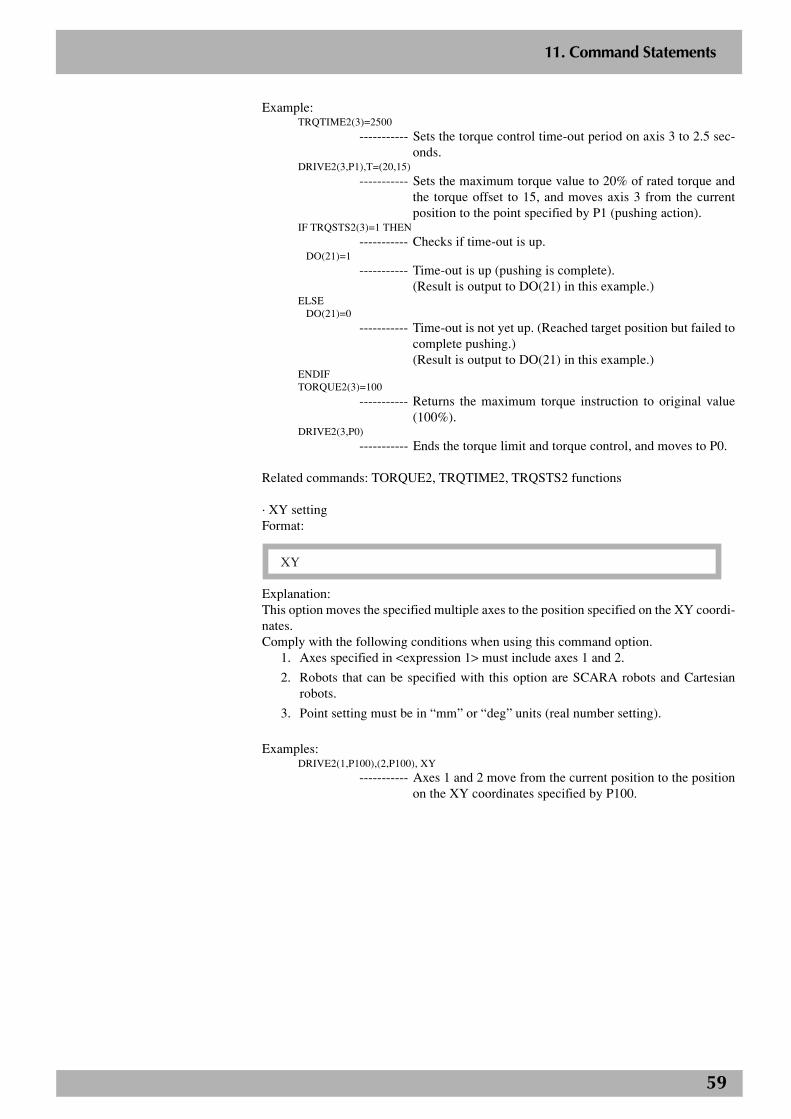
59
2
11. Command Statements
Example:TRQTIME2(3)=2500
----------- Sets the torque control time-out period on axis 3 to 2.5 sec-onds.
DRIVE2(3,P1),T=(20,15)
----------- Sets the maximum torque value to 20% of rated torque andthe torque offset to 15, and moves axis 3 from the currentposition to the point specified by P1 (pushing action).
IF TRQSTS2(3)=1 THEN
----------- Checks if time-out is up.DO(21)=1
----------- Time-out is up (pushing is complete).(Result is output to DO(21) in this example.)
ELSEDO(21)=0
----------- Time-out is not yet up. (Reached target position but failed tocomplete pushing.)(Result is output to DO(21) in this example.)
ENDIFTORQUE2(3)=100
----------- Returns the maximum torque instruction to original value(100%).
DRIVE2(3,P0)
----------- Ends the torque limit and torque control, and moves to P0.
Related commands: TORQUE2, TRQTIME2, TRQSTS2 functions
· XY settingFormat:
XY
Explanation:This option moves the specified multiple axes to the position specified on the XY coordi-nates.Comply with the following conditions when using this command option.
1. Axes specified in <expression 1> must include axes 1 and 2.
2. Robots that can be specified with this option are SCARA robots and Cartesianrobots.
3. Point setting must be in “mm” or “deg” units (real number setting).
Examples:DRIVE2(1,P100),(2,P100), XY
----------- Axes 1 and 2 move from the current position to the positionon the XY coordinates specified by P100.
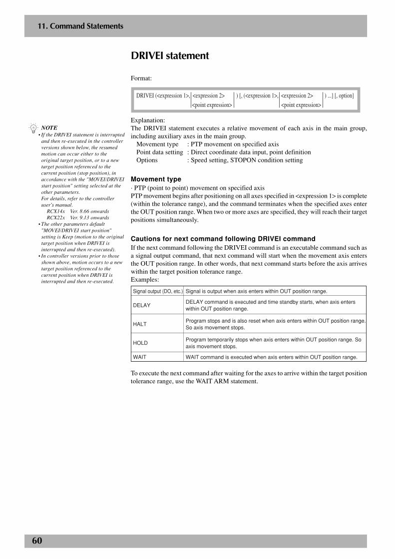
60
2
11. Command Statements
DRIVEI statement
Format:
DRIVEI (<expression 1>, <expression 2> ) [, (<expression 1>, <expression 2> ) ...] [, option]
<point expression> <point expression>
Explanation:The DRIVEI statement executes a relative movement of each axis in the main group,including auxiliary axes in the main group.
Movement type : PTP movement on specified axisPoint data setting : Direct coordinate data input, point definitionOptions : Speed setting, STOPON condition setting
Movement type· PTP (point to point) movement on specified axisPTP movement begins after positioning on all axes specified in <expression 1> is complete(within the tolerance range), and the command terminates when the specified axes enterthe OUT position range. When two or more axes are specified, they will reach their targetpositions simultaneously.
Cautions for next command following DRIVEI commandIf the next command following the DRIVEI command is an executable command such asa signal output command, that next command will start when the movement axis entersthe OUT position range. In other words, that next command starts before the axis arriveswithin the target position tolerance range.Examples:
Signal output (DO, etc.)
DELAY
HALT
HOLD
WAIT
Signal is output when axis enters within OUT position range.
DELAY command is executed and time standby starts, when axis enters within OUT position range.
Program stops and is also reset when axis enters within OUT position range. So axis movement stops.
Program temporarily stops when axis enters within OUT position range. So axis movement stops.
WAIT command is executed when axis enters within OUT position range.
To execute the next command after waiting for the axes to arrive within the target positiontolerance range, use the WAIT ARM statement.
n NOTE• If the DRIVEI statement is interrupted
and then re-executed in the controllerversions shown below, the resumedmotion can occur either to theoriginal target position, or to a newtarget position referenced to thecurrent position (stop position), inaccordance with the "MOVEI/DRIVEIstart position" setting selected at theother parameters.For details, refer to the controlleruser's manual.
RCX14x Ver. 8.66 onwardsRCX22x Ver. 9.13 onwards
• The other parameters default"MOVEI/DRIVEI start position"setting is Keep (motion to the originaltarget position when DRIVEI isinterrupted and then re-executed).
• In controller versions prior to thoseshown above, motion occurs to a newtarget position referenced to thecurrent position when DRIVEI isinterrupted and then re-executed.
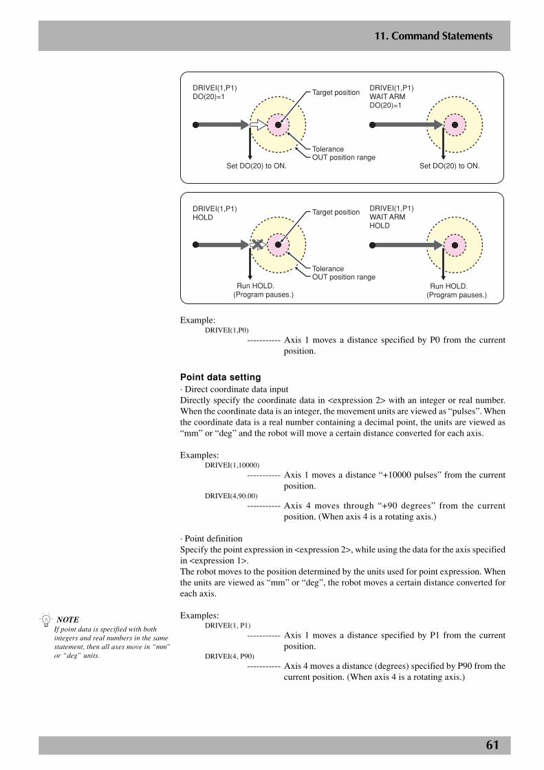
61
2
11. Command Statements
P1
Set DO(20) to ON.
DRIVEI(1,P1)WAIT ARMDO(20)=1
Set DO(20) to ON.
DRIVEI(1,P1)DO(20)=1
Tolerance
Target position
OUT position range
Run HOLD.(Program pauses.)
DRIVEI(1,P1)WAIT ARMHOLD
DRIVEI(1,P1)HOLD
ToleranceOUT position range
Target position
Run HOLD.(Program pauses.)
Example:DRIVEI(1,P0)
----------- Axis 1 moves a distance specified by P0 from the currentposition.
Point data setting· Direct coordinate data inputDirectly specify the coordinate data in <expression 2> with an integer or real number.When the coordinate data is an integer, the movement units are viewed as “pulses”. Whenthe coordinate data is a real number containing a decimal point, the units are viewed as“mm” or “deg” and the robot will move a certain distance converted for each axis.
Examples:DRIVEI(1,10000)
----------- Axis 1 moves a distance “+10000 pulses” from the currentposition.
DRIVEI(4,90.00)
----------- Axis 4 moves through “+90 degrees” from the currentposition. (When axis 4 is a rotating axis.)
· Point definitionSpecify the point expression in <expression 2>, while using the data for the axis specifiedin <expression 1>.The robot moves to the position determined by the units used for point expression. Whenthe units are viewed as “mm” or “deg”, the robot moves a certain distance converted foreach axis.
Examples:DRIVEI(1, P1)
----------- Axis 1 moves a distance specified by P1 from the currentposition.
DRIVEI(4, P90)----------- Axis 4 moves a distance (degrees) specified by P90 from the
current position. (When axis 4 is a rotating axis.)
n NOTEIf point data is specified with bothintegers and real numbers in the samestatement, then all axes move in “mm”or “deg” units.
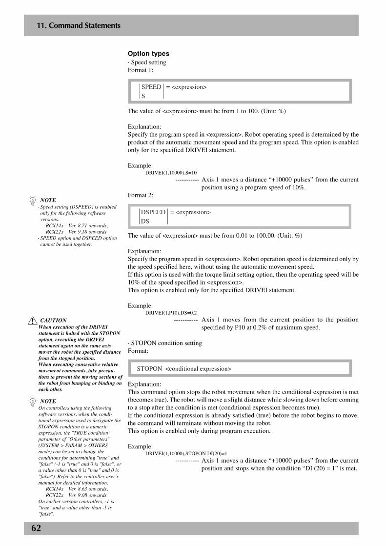
62
2
11. Command Statements
Option types· Speed settingFormat 1:
SPEED = <expression>
S
The value of <expression> must be from 1 to 100. (Unit: %)
Explanation:Specify the program speed in <expression>. Robot operating speed is determined by theproduct of the automatic movement speed and the program speed. This option is enabledonly for the specified DRIVEI statement.
Example:DRIVEI(1,10000),S=10
----------- Axis 1 moves a distance “+10000 pulses” from the currentposition using a program speed of 10%.
Format 2:
DSPEED = <expression>
DS
The value of <expression> must be from 0.01 to 100.00. (Unit: %)
Explanation:Specify the program speed in <expression>. Robot operation speed is determined only bythe speed specified here, without using the automatic movement speed.If this option is used with the torque limit setting option, then the operating speed will be10% of the speed specified in <expression>.This option is enabled only for the specified DRIVEI statement.
Example:DRIVEI(1,P10),DS=0.2
----------- Axis 1 moves from the current position to the positionspecified by P10 at 0.2% of maximum speed.
· STOPON condition settingFormat:
STOPON <conditional expression>
Explanation:This command option stops the robot movement when the conditional expression is met(becomes true). The robot will move a slight distance while slowing down before comingto a stop after the condition is met (conditional expression becomes true).If the conditional expression is already satisfied (true) before the robot begins to move,the command will terminate without moving the robot.This option is enabled only during program execution.
Example:DRIVEI(1,10000),STOPON DI(20)=1
----------- Axis 1 moves a distance “+10000 pulses” from the currentposition and stops when the condition “DI (20) = 1” is met.
c CAUTIONWhen execution of the DRIVEIstatement is halted with the STOPONoption, executing the DRIVEIstatement again on the same axismoves the robot the specified distancefrom the stopped position.When executing consecutive relativemovement commands, take precau-tions to prevent the moving sections ofthe robot from bumping or binding oneach other.
n NOTEOn controllers using the followingsoftware versions, when the condi-tional expression used to designate theSTOPON condition is a numericexpression, the "TRUE condition"parameter of "Other parameters"(SYSTEM > PARAM > OTHERSmode) can be set to change theconditions for determining "true" and"false" (-1 is "true" and 0 is "false", ora value other than 0 is "true" and 0 is"false"). Refer to the controller user'smanual for detailed information.
RCX14x Ver. 8.63 onwards,RCX22x Ver. 9.08 onwards
On earlier version controllers, -1 is"true" and a value other than -1 is"false".
n NOTE· Speed setting (DSPEED) is enabled
only for the following softwareversions.
RCX14x Ver. 8.71 onwards,RCX22x Ver. 9.18 onwards
· SPEED option and DSPEED optioncannot be used together.
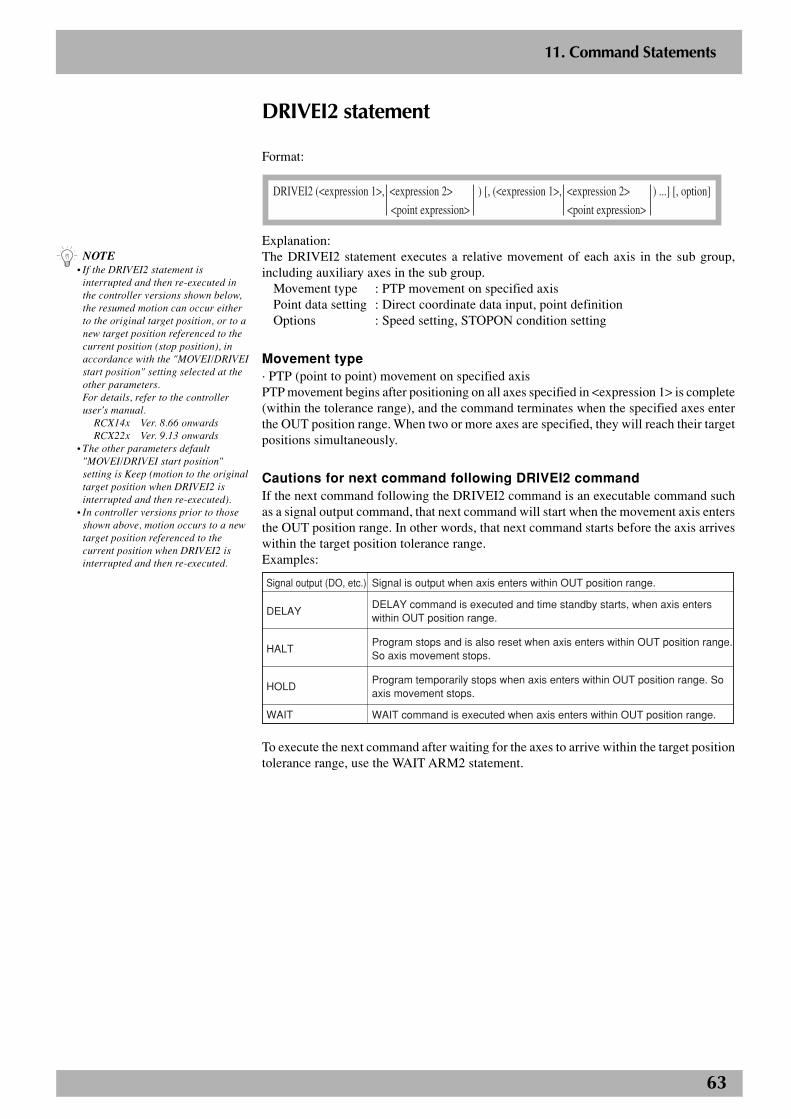
63
2
11. Command Statements
DRIVEI2 statement
Format:
DRIVEI2 (<expression 1>, <expression 2> ) [, (<expression 1>, <expression 2> ) ...] [, option]
<point expression> <point expression>
Explanation:The DRIVEI2 statement executes a relative movement of each axis in the sub group,including auxiliary axes in the sub group.
Movement type : PTP movement on specified axisPoint data setting : Direct coordinate data input, point definitionOptions : Speed setting, STOPON condition setting
Movement type· PTP (point to point) movement on specified axisPTP movement begins after positioning on all axes specified in <expression 1> is complete(within the tolerance range), and the command terminates when the specified axes enterthe OUT position range. When two or more axes are specified, they will reach their targetpositions simultaneously.
Cautions for next command following DRIVEI2 commandIf the next command following the DRIVEI2 command is an executable command suchas a signal output command, that next command will start when the movement axis entersthe OUT position range. In other words, that next command starts before the axis arriveswithin the target position tolerance range.Examples:
Signal output (DO, etc.)
DELAY
HALT
HOLD
WAIT
Signal is output when axis enters within OUT position range.
DELAY command is executed and time standby starts, when axis enters within OUT position range.
Program stops and is also reset when axis enters within OUT position range. So axis movement stops.
Program temporarily stops when axis enters within OUT position range. So axis movement stops.
WAIT command is executed when axis enters within OUT position range.
To execute the next command after waiting for the axes to arrive within the target positiontolerance range, use the WAIT ARM2 statement.
n NOTE• If the DRIVEI2 statement is
interrupted and then re-executed inthe controller versions shown below,the resumed motion can occur eitherto the original target position, or to anew target position referenced to thecurrent position (stop position), inaccordance with the "MOVEI/DRIVEIstart position" setting selected at theother parameters.For details, refer to the controlleruser's manual.
RCX14x Ver. 8.66 onwardsRCX22x Ver. 9.13 onwards
• The other parameters default"MOVEI/DRIVEI start position"setting is Keep (motion to the originaltarget position when DRIVEI2 isinterrupted and then re-executed).
• In controller versions prior to thoseshown above, motion occurs to a newtarget position referenced to thecurrent position when DRIVEI2 isinterrupted and then re-executed.
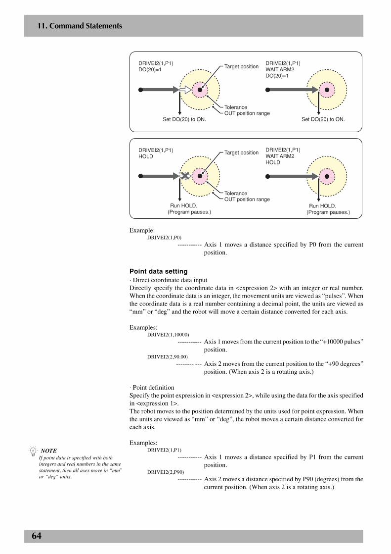
64
2
11. Command Statements
P1
Set DO(20) to ON.
DRIVEI2(1,P1)WAIT ARM2DO(20)=1
Set DO(20) to ON.
DRIVEI2(1,P1)DO(20)=1
Tolerance
Target position
OUT position range
Run HOLD.(Program pauses.)
DRIVEI2(1,P1)WAIT ARM2HOLD
DRIVEI2(1,P1)HOLD
ToleranceOUT position range
Target position
Run HOLD.(Program pauses.)
Example:DRIVEI2(1,P0)
----------- Axis 1 moves a distance specified by P0 from the currentposition.
Point data setting· Direct coordinate data inputDirectly specify the coordinate data in <expression 2> with an integer or real number.When the coordinate data is an integer, the movement units are viewed as “pulses”. Whenthe coordinate data is a real number containing a decimal point, the units are viewed as“mm” or “deg” and the robot will move a certain distance converted for each axis.
Examples:DRIVEI2(1,10000)
----------- Axis 1 moves from the current position to the “+10000 pulses”position.
DRIVEI2(2,90.00)
-------- --- Axis 2 moves from the current position to the “+90 degrees”position. (When axis 2 is a rotating axis.)
· Point definitionSpecify the point expression in <expression 2>, while using the data for the axis specifiedin <expression 1>.The robot moves to the position determined by the units used for point expression. Whenthe units are viewed as “mm” or “deg”, the robot moves a certain distance converted foreach axis.
Examples:DRIVEI2(1,P1)
----------- Axis 1 moves a distance specified by P1 from the currentposition.
DRIVEI2(2,P90)----------- Axis 2 moves a distance specified by P90 (degrees) from the
current position. (When axis 2 is a rotating axis.)
n NOTEIf point data is specified with bothintegers and real numbers in the samestatement, then all axes move in “mm”or “deg” units.
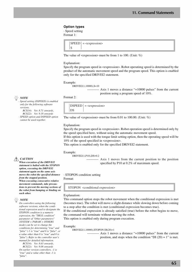
65
2
11. Command Statements
Option types· Speed settingFormat 1:
SPEED = <expression>
S
The value of <expression> must be from 1 to 100. (Unit: %)
Explanation:Specify the program speed in <expression>. Robot operatimg speed is determined by theproduct of the automatic movement speed and the program speed. This option is enabledonly for the specified DRIVEI2 statement.
Example:DRIVEI2(1,10000),S=10
----------- Axis 1 moves a distance “+10000 pulses” from the currentposition using a program speed of 10%.
Format 2:
DSPEED = <expression>
DS
The value of <expression> must be from 0.01 to 100.00. (Unit: %)
Explanation:Specify the program speed in <expression>. Robot operation speed is determined only bythe speed specified here, without using the automatic movement speed.If this option is used with the torque limit setting option, then the operating speed will be10% of the speed specified in <expression>.This option is enabled only for the specified DRIVEI2 statement.
Example:DRIVEI2(1,P10),DS=0.2
----------- Axis 1 moves from the current position to the positionspecified by P10 at 0.2% of maximum speed.
· STOPON condition settingFormat:
STOPON <conditional expression>
Explanation:This command option stops the robot movement when the conditional expression is met(becomes true). The robot will move a slight distance while slowing down before comingto a stop after the condition is met (conditional expression becomes true).If the conditional expression is already satisfied (true) before the robot begins to move,the command will terminate without moving the robot.This option is enabled only during program execution.
Example:DRIVEI2(1,10000),STOPON DI(20)=1
----------- Axis 1 moves a distance “+10000 pulses” from the currentposition, and stops when the condition “DI (20) = 1” is met.
c CAUTIONWhen execution of the DRIVEI2statement is halted with the STOPONoption, executing the DRIVEI2statement again on the same axismoves the robot the specified distancefrom the stopped position.When executing consecutive relativemovement commands, take precau-tions to prevent the moving sections ofthe robot from bumping or binding oneach other.
n NOTEOn controllers using the followingsoftware versions, when the condi-tional expression used to designate theSTOPON condition is a numericexpression, the "TRUE condition"parameter of "Other parameters"(SYSTEM > PARAM > OTHERSmode) can be set to change theconditions for determining "true" and"false" (-1 is "true" and 0 is "false", ora value other than 0 is "true" and 0 is"false"). Refer to the controller user'smanual for detailed information.
RCX14x Ver. 8.63 onwards,RCX22x Ver. 9.08 onwards
On earlier version controllers, -1 is"true" and a value other than -1 is"false".
n NOTE· Speed setting (DSPEED) is enabled
only for the following softwareversions.
RCX14x Ver. 8.71 onwards,RCX22x Ver. 9.18 onwards
· SPEED option and DSPEED optioncannot be used together.
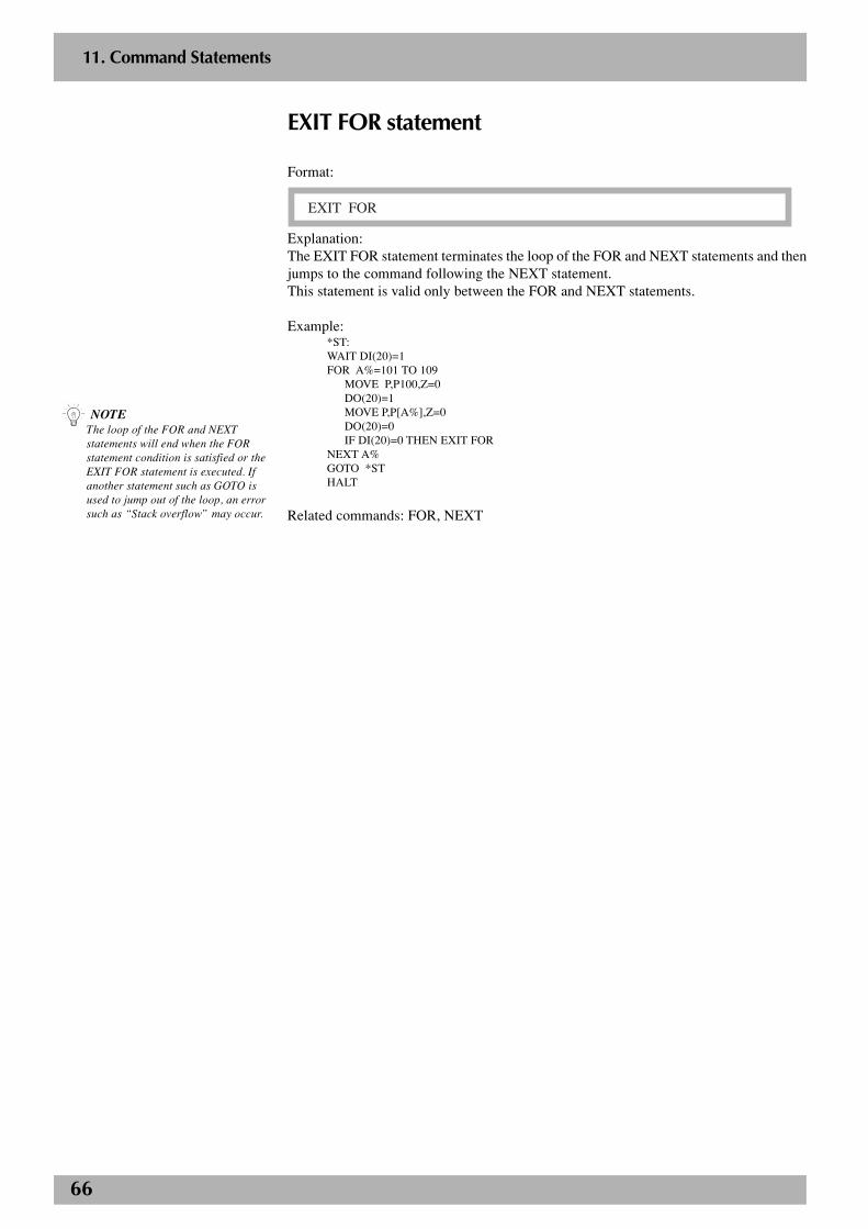
66
2
11. Command Statements
EXIT FOR statement
Format:
EXIT FOR
Explanation:The EXIT FOR statement terminates the loop of the FOR and NEXT statements and thenjumps to the command following the NEXT statement.This statement is valid only between the FOR and NEXT statements.
Example:*ST:WAIT DI(20)=1FOR A%=101 TO 109
MOVE P,P100,Z=0DO(20)=1MOVE P,P[A%],Z=0DO(20)=0IF DI(20)=0 THEN EXIT FOR
NEXT A%GOTO *STHALT
Related commands: FOR, NEXT
n NOTEThe loop of the FOR and NEXTstatements will end when the FORstatement condition is satisfied or theEXIT FOR statement is executed. Ifanother statement such as GOTO isused to jump out of the loop, an errorsuch as “Stack overflow” may occur.
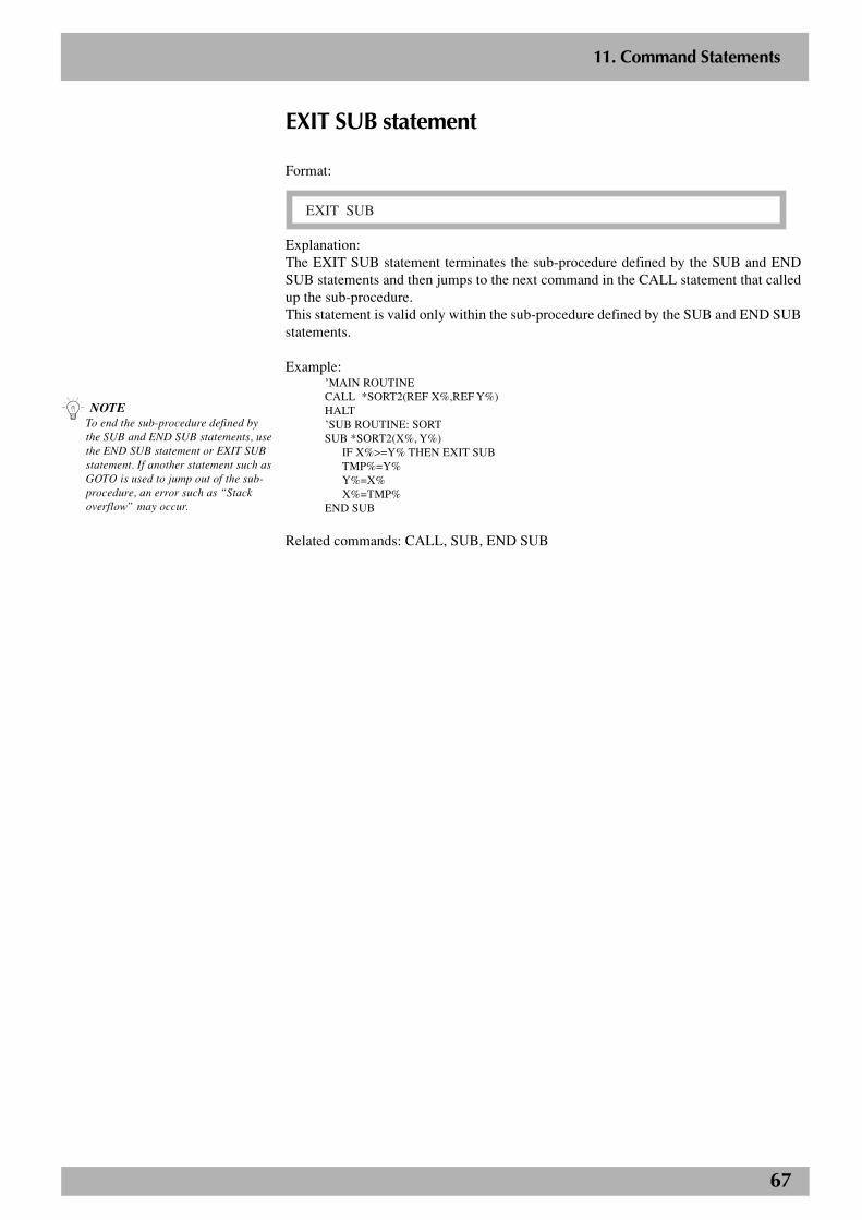
67
2
11. Command Statements
EXIT SUB statement
Format:
EXIT SUB
Explanation:The EXIT SUB statement terminates the sub-procedure defined by the SUB and ENDSUB statements and then jumps to the next command in the CALL statement that calledup the sub-procedure.This statement is valid only within the sub-procedure defined by the SUB and END SUBstatements.
Example:’MAIN ROUTINECALL *SORT2(REF X%,REF Y%)HALT’SUB ROUTINE: SORTSUB *SORT2(X%, Y%)
IF X%>=Y% THEN EXIT SUBTMP%=Y%Y%=X%X%=TMP%
END SUB
Related commands: CALL, SUB, END SUB
n NOTETo end the sub-procedure defined bythe SUB and END SUB statements, usethe END SUB statement or EXIT SUBstatement. If another statement such asGOTO is used to jump out of the sub-procedure, an error such as “Stackoverflow” may occur.
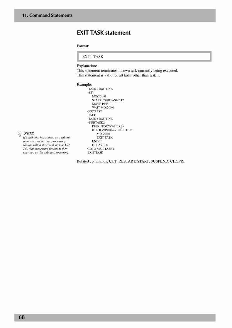
68
2
11. Command Statements
EXIT TASK statement
Format:
EXIT TASK
Explanation:This statement terminates its own task currently being executed.This statement is valid for all tasks other than task 1.
Example:’TASK1 ROUTINE*ST:
MO(20)=0START *SUBTASK2,T2MOVE P,P0,P1WAIT MO(20)=1
GOTO *STHALT’TASK2 ROUTINE*SUBTASK2:
P100=JTOXY(WHERE)IF LOCZ(P100)>=100.0 THEN
MO(20)=1EXIT TASK
ENDIFDELAY 100
GOTO *SUBTASK2EXIT TASK
Related commands: CUT, RESTART, START, SUSPEND, CHGPRI
n NOTEIf a task that has started as a subtaskjumps to another task processingroutine with a statement such as GOTO, that processing routine is thenexecuted as this subtask processing.
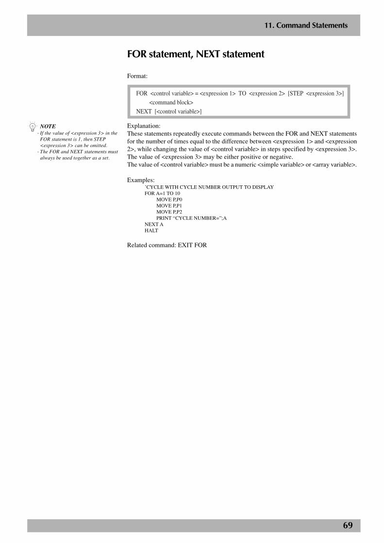
69
2
11. Command Statements
FOR statement, NEXT statement
Format:
FOR <control variable> = <expression 1> TO <expression 2> [STEP <expression 3>]
<command block>
NEXT [<control variable>]
Explanation:These statements repeatedly execute commands between the FOR and NEXT statementsfor the number of times equal to the difference between <expression 1> and <expression2>, while changing the value of <control variable> in steps specified by <expression 3>.The value of <expression 3> may be either positive or negative.The value of <control variable> must be a numeric <simple variable> or <array variable>.
Examples:’CYCLE WITH CYCLE NUMBER OUTPUT TO DISPLAYFOR A=1 TO 10
MOVE P,P0MOVE P,P1MOVE P,P2PRINT “CYCLE NUMBER=”;A
NEXT AHALT
Related command: EXIT FOR
n NOTE· If the value of <expression 3> in the
FOR statement is 1, then STEP<expression 3> can be omitted.
· The FOR and NEXT statements mustalways be used together as a set.
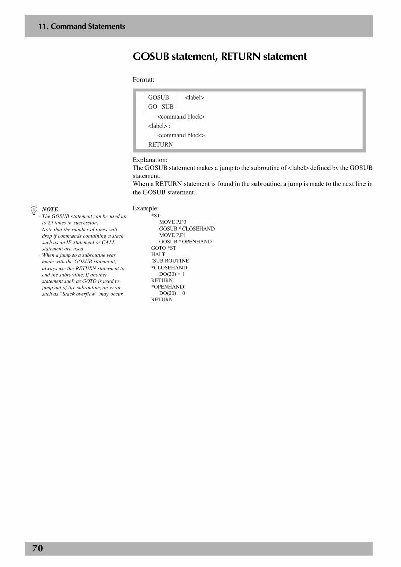
70
2
11. Command Statements
GOSUB statement, RETURN statement
Format:
GOSUB <label>
GO SUB
<command block>
<label> :
<command block>
RETURN
Explanation:The GOSUB statement makes a jump to the subroutine of <label> defined by the GOSUBstatement.When a RETURN statement is found in the subroutine, a jump is made to the next line inthe GOSUB statement.
Example:*ST:
MOVE P,P0GOSUB *CLOSEHANDMOVE P,P1GOSUB *OPENHAND
GOTO *STHALT’SUB ROUTINE*CLOSEHAND:
DO(20) = 1RETURN*OPENHAND:
DO(20) = 0RETURN
n NOTE· The GOSUB statement can be used up
to 29 times in succession.Note that the number of times willdrop if commands containing a stacksuch as an IF statement or CALLstatement are used.
· When a jump to a subroutine wasmade with the GOSUB statement,always use the RETURN statement toend the subroutine. If anotherstatement such as GOTO is used tojump out of the subroutine, an errorsuch as “Stack overflow” may occur.
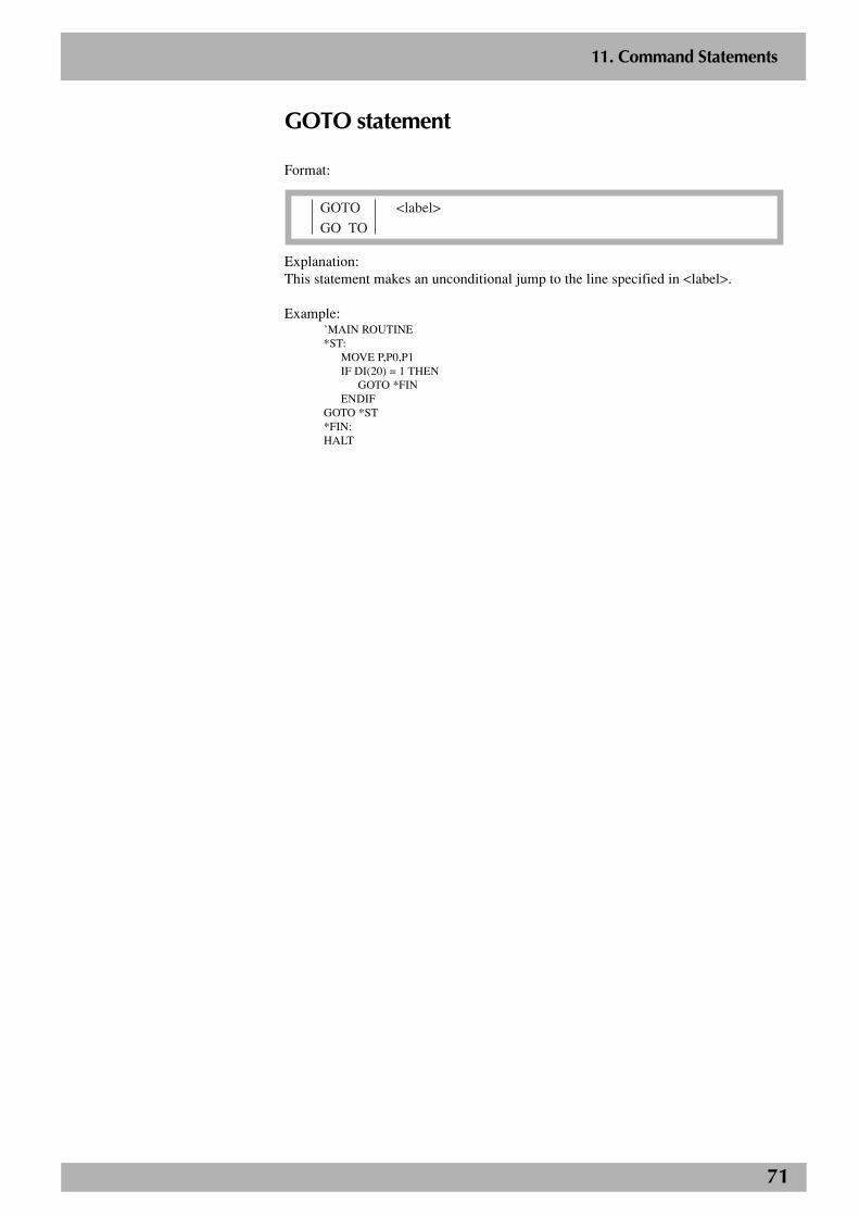
71
2
11. Command Statements
GOTO statement
Format:
GOTO <label>
GO TO
Explanation:This statement makes an unconditional jump to the line specified in <label>.
Example:’MAIN ROUTINE*ST:
MOVE P,P0,P1IF DI(20) = 1 THEN
GOTO *FINENDIF
GOTO *ST*FIN:HALT
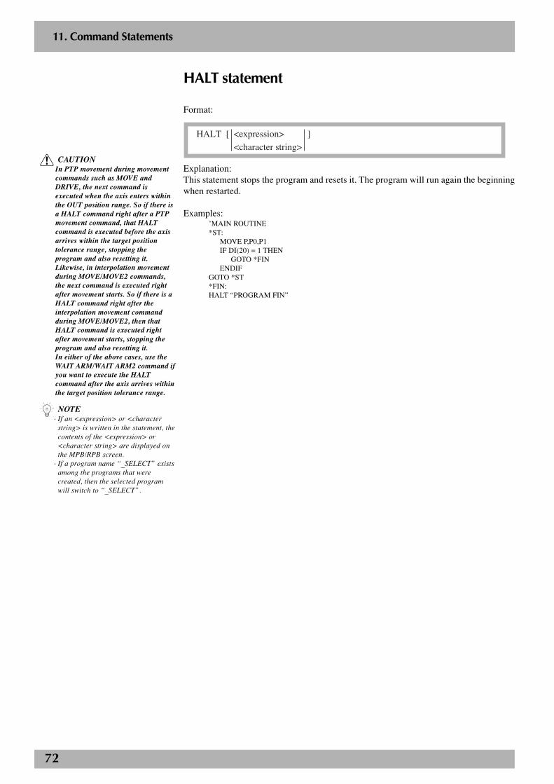
72
2
11. Command Statements
HALT statement
Format:
HALT [ <expression> ]
<character string>
Explanation:This statement stops the program and resets it. The program will run again the beginningwhen restarted.
Examples:’MAIN ROUTINE*ST:
MOVE P,P0,P1IF DI(20) = 1 THEN
GOTO *FINENDIF
GOTO *ST*FIN:HALT “PROGRAM FIN”
n NOTE· If an <expression> or <character
string> is written in the statement, thecontents of the <expression> or<character string> are displayed onthe MPB/RPB screen.
· If a program name “_SELECT” existsamong the programs that werecreated, then the selected programwill switch to “_SELECT”.
c CAUTIONIn PTP movement during movementcommands such as MOVE andDRIVE, the next command isexecuted when the axis enters withinthe OUT position range. So if there isa HALT command right after a PTPmovement command, that HALTcommand is executed before the axisarrives within the target positiontolerance range, stopping theprogram and also resetting it.Likewise, in interpolation movementduring MOVE/MOVE2 commands,the next command is executed rightafter movement starts. So if there is aHALT command right after theinterpolation movement commandduring MOVE/MOVE2, then thatHALT command is executed rightafter movement starts, stopping theprogram and also resetting it.In either of the above cases, use theWAIT ARM/WAIT ARM2 command ifyou want to execute the HALTcommand after the axis arrives withinthe target position tolerance range.
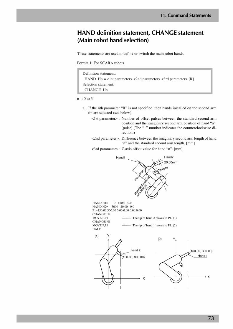
73
2
11. Command Statements
HAND definition statement, CHANGE statement(Main robot hand selection)
These statements are used to define or switch the main robot hands.
Format 1: For SCARA robots
Definition statement:
HAND Hn = <1st parameter> <2nd parameter> <3rd parameter> [R]
Selection statement:
CHANGE Hn
n : 0 to 3
a. If the 4th parameter “R” is not specified, then hands installed on the second armtip are selected (see below).
<1st parameter> : Number of offset pulses between the standard second armposition and the imaginary second arm position of hand “n”.[pulse] (The “+” number indicates the counterclockwise di-rection.)
<2nd parameter> : Difference between the imaginary second arm length of hand“n” and the standard second arm length. [mm]
<3rd parameter> : Z-axis offset value for hand “n”. [mm]
Hand1 Hand2
20.00mm
150.
00m
m
stan
dard
sec
ond
arm
leng
th
-5000pulses
HAND H1= 0 150.0 0.0HAND H2= -5000 20.00 0.0P1=150.00 300.00 0.00 0.00 0.00 0.00CHANGE H2MOVE P,P1 --------- The tip of hand 2 moves to P1. (1)CHANGE H1MOVE P,P1 --------- The tip of hand 1 moves to P1. (2)HALT
Y
X
hand 2
(150.00, 300.00)
(1)(2)
Hand1
X
Y
(150.00, 300.00)
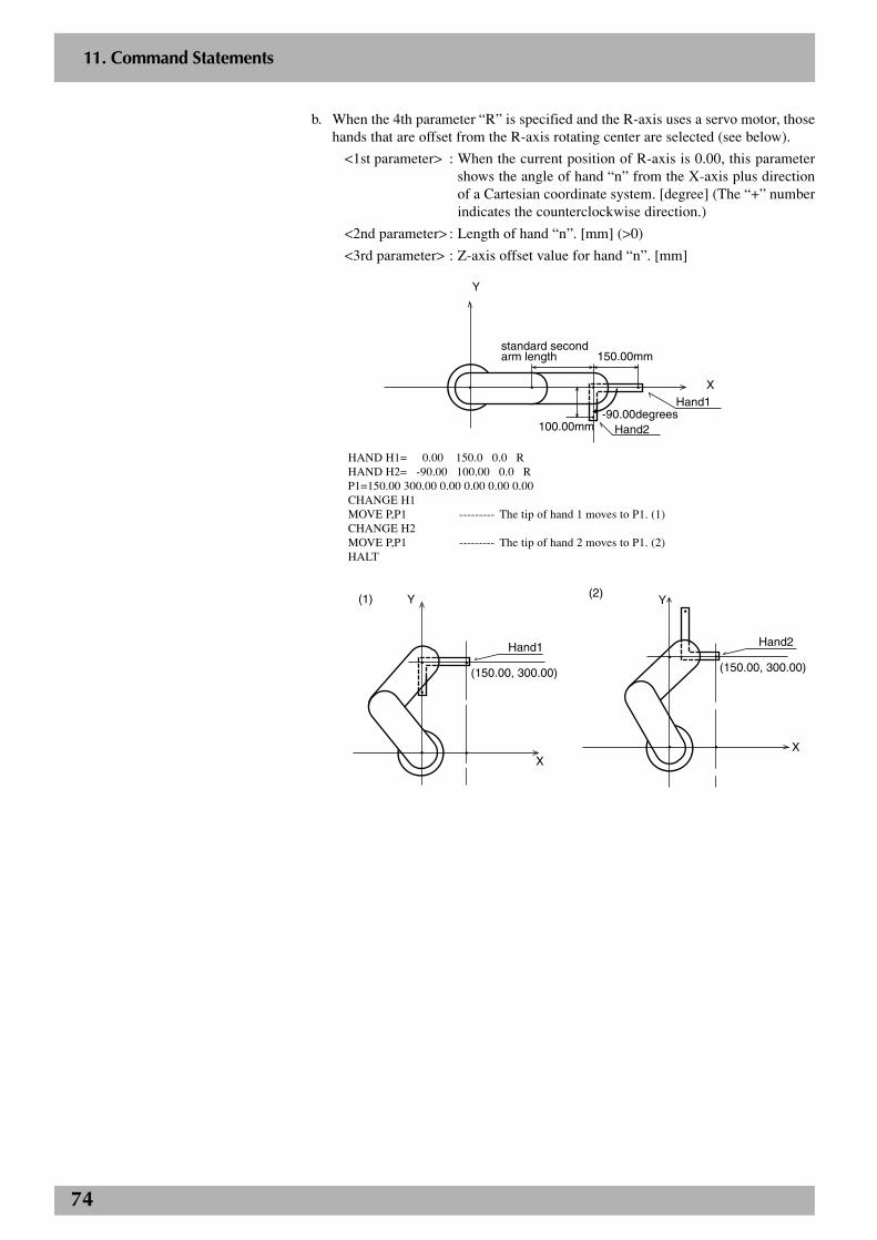
74
2
11. Command Statements
b. When the 4th parameter “R” is specified and the R-axis uses a servo motor, thosehands that are offset from the R-axis rotating center are selected (see below).
<1st parameter> : When the current position of R-axis is 0.00, this parametershows the angle of hand “n” from the X-axis plus directionof a Cartesian coordinate system. [degree] (The “+” numberindicates the counterclockwise direction.)
<2nd parameter> : Length of hand “n”. [mm] (>0)
<3rd parameter> : Z-axis offset value for hand “n”. [mm]
standard second arm length 150.00mm
100.00mm Hand2
Hand1
X
Y
-90.00degrees
HAND H1= 0.00 150.0 0.0 RHAND H2= -90.00 100.00 0.0 RP1=150.00 300.00 0.00 0.00 0.00 0.00CHANGE H1MOVE P,P1 --------- The tip of hand 1 moves to P1. (1)CHANGE H2MOVE P,P1 --------- The tip of hand 2 moves to P1. (2)HALT
(1)
X
Y
Hand1
(150.00, 300.00)
(2)
X
Y
Hand2
(150.00, 300.00)

75
2
11. Command Statements
Format 2: For Cartesian robots
Definition statement:
HAND Hn = <1st parameter> <2nd parameter> <3rd parameter> [R]
Selection statement:
CHANGE Hn
n: 0 to 3
a. If the 4th parameter “R” is not specified, hands installed on the second arm tip areselected (see below).
<1st parameter> : X-axis offset value for hand “n”. [mm]
<2nd parameter> : Y-axis offset value for hand “n”. [mm]
<3rd parameter> : Z-axis offset value for hand “n”. [mm]
-100.00mm
100.00mm
Hand2
Hand1
X
Y
HAND H1= 0.00 0.00 0.00HAND H2= 100.0 -100.0 -100.0P1=200.00 250.00 0.00 0.00 0.00 0.00CHANGE H2MOVE P,P1 --------- The tip of hand 2 moves to P1. (1)CHANGE H1MOVE P,P1 --------- The tip of hand 1 moves to P1. (2)HALT
(1)
X
(200.00, 250.00)
Hand2
Y
(2)
Hand1
X
Y
(200.00, 250.00)
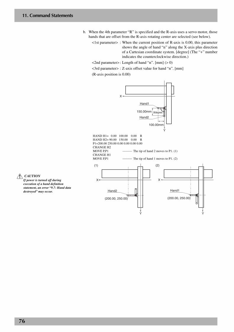
76
2
11. Command Statements
b. When the 4th parameter “R” is specified and the R-axis uses a servo motor, thosehands that are offset from the R-axis rotating center are selected (see below).
<1st parameter> : When the current position of R-axis is 0.00, this parametershows the angle of hand “n” along the X-axis plus directionof a Cartesian coordinate system. [degree] (The “+” numberindicates the counterclockwise direction.)
<2nd parameter> : Length of hand “n”. [mm] (> 0)
<3rd parameter> : Z-axis offset value for hand “n”. [mm]
(R-axis position is 0.00)
X
Y
100.00mm
150.00mm
Hand2
Hand1
90degrees90degrees90degrees
HAND H1= 0.00 100.00 0.00 RHAND H2= 90.00 150.00 0.00 RP1=200.00 250.00 0.00 0.00 0.00 0.00CHANGE H2MOVE P,P1 --------- The tip of hand 2 moves to P1. (1)CHANGE H1MOVE P,P1 --------- The tip of hand 1 moves to P1. (2)
(1)
X
(200.00, 250.00)
Hand2
Y
(2)
X
Hand1
Y
(200.00, 250.00)
c CAUTIONIf power is turned off duringexecution of a hand definitionstatement, an error “9.7: Hand datadestroyed” may occur.
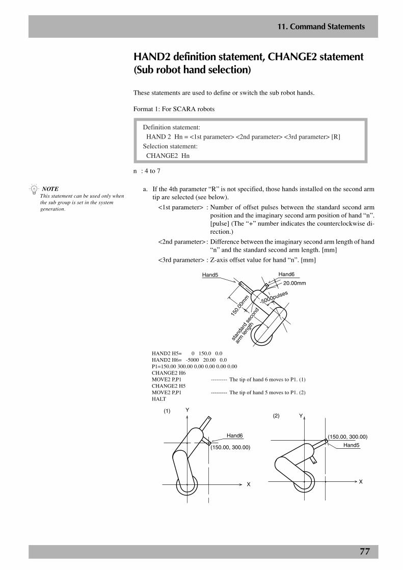
77
2
11. Command Statements
HAND2 definition statement, CHANGE2 statement(Sub robot hand selection)
These statements are used to define or switch the sub robot hands.
Format 1: For SCARA robots
Definition statement:
HAND 2 Hn = <1st parameter> <2nd parameter> <3rd parameter> [R]
Selection statement:
CHANGE2 Hn
n : 4 to 7
a. If the 4th parameter “R” is not specified, those hands installed on the second armtip are selected (see below).
<1st parameter> : Number of offset pulses between the standard second armposition and the imaginary second arm position of hand “n”.[pulse] (The “+” number indicates the counterclockwise di-rection.)
<2nd parameter> : Difference between the imaginary second arm length of hand“n” and the standard second arm length. [mm]
<3rd parameter> : Z-axis offset value for hand “n”. [mm]
Hand5 Hand6
20.00mm
150.
00m
m
stan
dard
sec
ond
arm
leng
th
-5000pulses
HAND2 H5= 0 150.0 0.0HAND2 H6= -5000 20.00 0.0P1=150.00 300.00 0.00 0.00 0.00 0.00CHANGE2 H6MOVE2 P,P1 --------- The tip of hand 6 moves to P1. (1)CHANGE2 H5MOVE2 P,P1 --------- The tip of hand 5 moves to P1. (2)HALT
Y
X
Hand6
(150.00, 300.00)
(1)(2)
Hand5
X
Y
(150.00, 300.00)
n NOTEThis statement can be used only whenthe sub group is set in the systemgeneration.
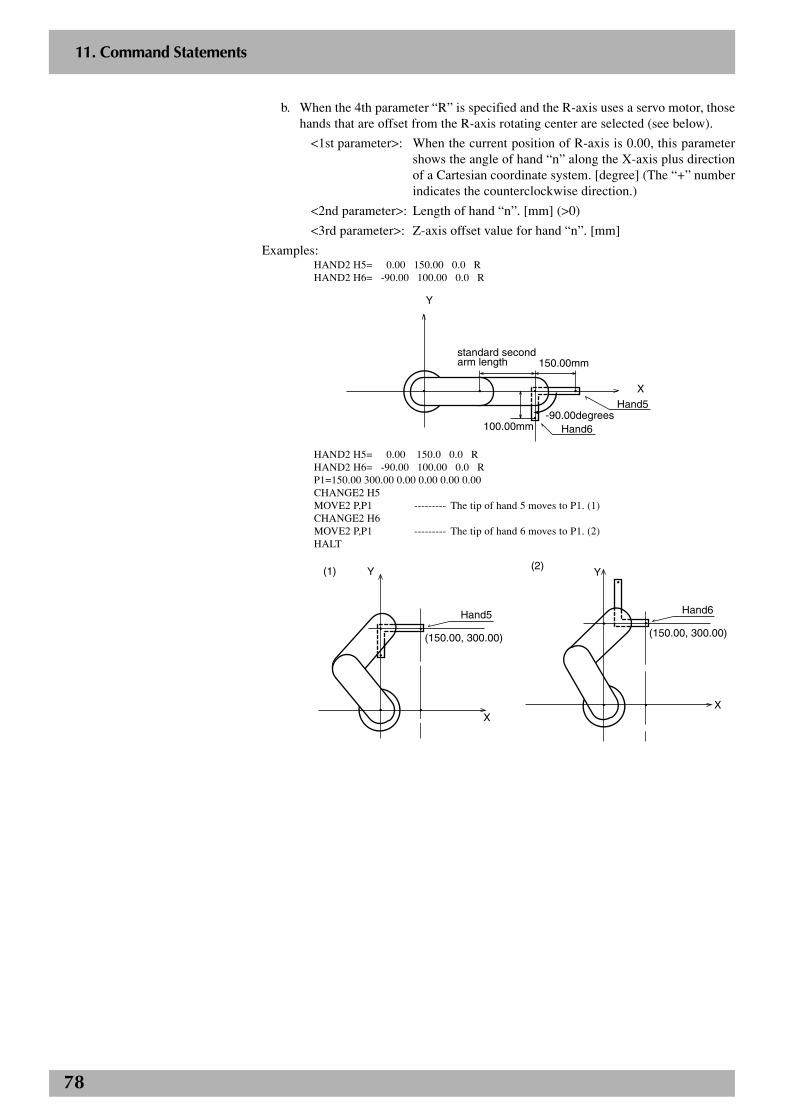
78
2
11. Command Statements
b. When the 4th parameter “R” is specified and the R-axis uses a servo motor, thosehands that are offset from the R-axis rotating center are selected (see below).
<1st parameter>: When the current position of R-axis is 0.00, this parametershows the angle of hand “n” along the X-axis plus directionof a Cartesian coordinate system. [degree] (The “+” numberindicates the counterclockwise direction.)
<2nd parameter>: Length of hand “n”. [mm] (>0)
<3rd parameter>: Z-axis offset value for hand “n”. [mm]
Examples:HAND2 H5= 0.00 150.00 0.0 RHAND2 H6= -90.00 100.00 0.0 R
standard second arm length 150.00mm
100.00mm Hand6
Hand5
X
Y
-90.00degrees
HAND2 H5= 0.00 150.0 0.0 RHAND2 H6= -90.00 100.00 0.0 RP1=150.00 300.00 0.00 0.00 0.00 0.00CHANGE2 H5MOVE2 P,P1 --------- The tip of hand 5 moves to P1. (1)CHANGE2 H6MOVE2 P,P1 --------- The tip of hand 6 moves to P1. (2)HALT
(1)
X
Y
Hand5
(150.00, 300.00)
(2)
X
Y
Hand6
(150.00, 300.00)
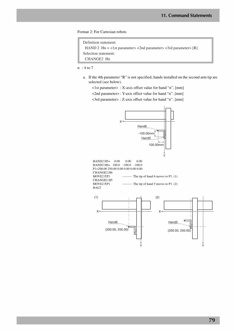
79
2
11. Command Statements
Format 2: For Cartesian robots
Definition statement:
HAND 2 Hn = <1st parameter> <2nd parameter> <3rd parameter> [R]
Selection statement:
CHANGE2 Hn
n : 4 to 7
a. If the 4th parameter “R” is not specified, hands installed on the second arm tip areselected (see below).
<1st parameter> : X-axis offset value for hand “n”. [mm]
<2nd parameter> : Y-axis offset value for hand “n”. [mm]
<3rd parameter> : Z-axis offset value for hand “n”. [mm]
-100.00mm
100.00mm
Hand6
Hand5
X
Y
HAND2 H5= 0.00 0.00 0.00HAND2 H6= 100.0 -100.0 -100.0P1=200.00 250.00 0.00 0.00 0.00 0.00CHANGE2 H6MOVE2 P,P1 --------- The tip of hand 6 moves to P1. (1)CHANGE2 H5MOVE2 P,P1 --------- The tip of hand 5 moves to P1. (2)HALT
(1)
X
(200.00, 250.00)
Hand6
Y
(2)
X
Hand5
Y
(200.00, 250.00)
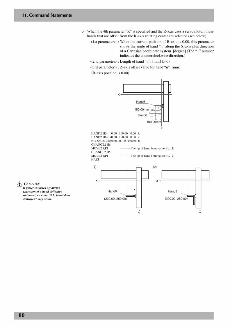
80
2
11. Command Statements
b. When the 4th parameter “R” is specified and the R-axis uses a servo motor, thosehands that are offset from the R-axis rotating center are selected (see below).
<1st parameter> : When the current position of R-axis is 0.00, this parametershows the angle of hand “n” along the X-axis plus directionof a Cartesian coordinate system. [degree] (The “+” numberindicates the counterclockwise direction.)
<2nd parameter> : Length of hand “n”. [mm] (> 0)
<3rd parameter> : Z-axis offset value for hand “n”. [mm]
(R-axis position is 0.00)
X
Y
100.00mm
150.00mm
Hand5
Hand6
90degrees90degrees90degrees
HAND2 H5= 0.00 100.00 0.00 RHAND2 H6= 90.00 150.00 0.00 RP1=200.00 250.00 0.00 0.00 0.00 0.00CHANGE2 H6MOVE2 P,P1 --------- The tip of hand 6 moves to P1. (1)CHANGE2 H5MOVE2 P,P1 --------- The tip of hand 5 moves to P1. (2)HALT
(1)
X
(200.00, 250.00)
Hand6
Y
(2)
X
Hand5
Y
(200.00, 250.00)
c CAUTIONIf power is turned off duringexecution of a hand definitionstatement, an error “9.7: Hand datadestroyed” may occur.

81
2
11. Command Statements
HOLD statement
Format:
HOLD [ <expression> ]
<character string>
Explanation:This statement temporarily pauses execution of the program. When the program is re-executed, it begins from the line following the HOLD statement.
Example:’MAIN ROUTINE*ST:
MOVE P,P0,P1IF DI(20)=1 THEN
HOLD “PROGRAM STOP”ENDIF
GOTO *STHALT
n NOTEIf an <expression> or <characterstring> is written in the statement, thecontents of the <expression> or<character string> are displayed onthe MPB/RPB screen.
c CAUTIONIn PTP movement during movementcommands such as MOVE andDRIVE, the next command isexecuted when the axis enters withinthe OUT position range. So if there isa HOLD command right after a PTPmovement command, that HOLDcommand is executed before the axisarrives within the target positiontolerance range, causing the programto stop.Likewise, in interpolation movementduring MOVE/MOVE2 commands,the next command is executed rightafter movement starts. So if there is aHOLD command right after theinterpolation movement commandduring MOVE/MOVE2, then thatHOLD command is executed rightafter movement starts, causing theprogram to stop.In either of the above cases, use theWAIT ARM/WAIT ARM2 command ifyou want to execute the HOLDcommand after the axis arrives withinthe target position tolerance range.
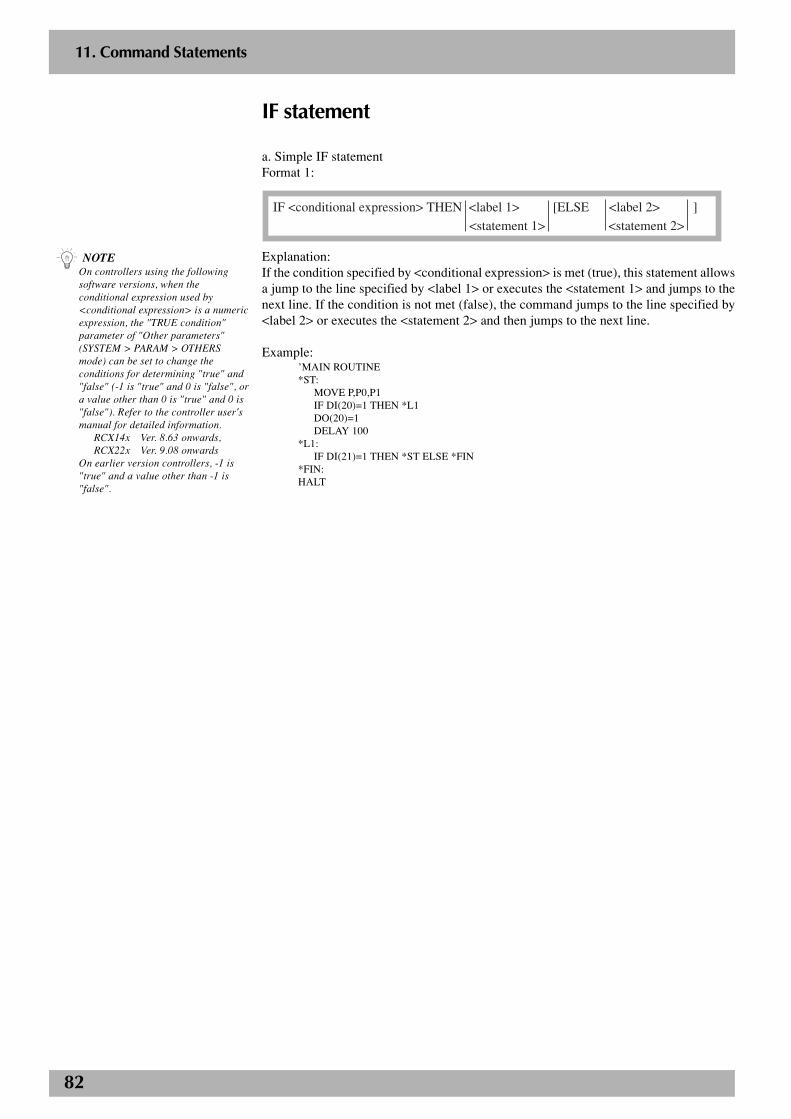
82
2
11. Command Statements
IF statement
a. Simple IF statementFormat 1:
IF <conditional expression> THEN <label 1> [ELSE <label 2> ]
<statement 1> <statement 2>
Explanation:If the condition specified by <conditional expression> is met (true), this statement allowsa jump to the line specified by <label 1> or executes the <statement 1> and jumps to thenext line. If the condition is not met (false), the command jumps to the line specified by<label 2> or executes the <statement 2> and then jumps to the next line.
Example:’MAIN ROUTINE*ST:
MOVE P,P0,P1IF DI(20)=1 THEN *L1DO(20)=1DELAY 100
*L1:IF DI(21)=1 THEN *ST ELSE *FIN
*FIN:HALT
n NOTEOn controllers using the followingsoftware versions, when theconditional expression used by<conditional expression> is a numericexpression, the "TRUE condition"parameter of "Other parameters"(SYSTEM > PARAM > OTHERSmode) can be set to change theconditions for determining "true" and"false" (-1 is "true" and 0 is "false", ora value other than 0 is "true" and 0 is"false"). Refer to the controller user'smanual for detailed information.
RCX14x Ver. 8.63 onwards,RCX22x Ver. 9.08 onwards
On earlier version controllers, -1 is"true" and a value other than -1 is"false".
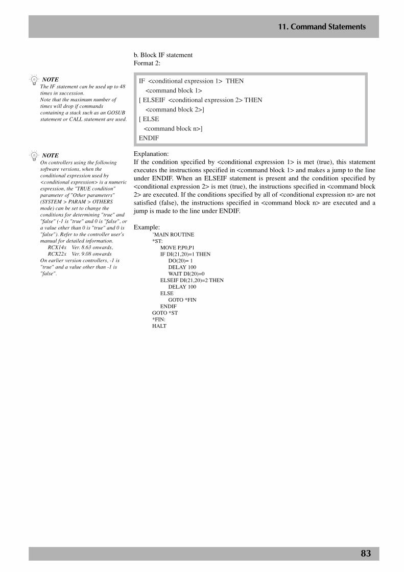
83
2
11. Command Statements
b. Block IF statementFormat 2:
IF <conditional expression 1> THEN
<command block 1>
[ ELSEIF <conditional expression 2> THEN
<command block 2>]
[ ELSE
<command block n>]
ENDIF
Explanation:If the condition specified by <conditional expression 1> is met (true), this statementexecutes the instructions specified in <command block 1> and makes a jump to the lineunder ENDIF. When an ELSEIF statement is present and the condition specified by<conditional expression 2> is met (true), the instructions specified in <command block2> are executed. If the conditions specified by all of <conditional expression n> are notsatisfied (false), the instructions specified in <command block n> are executed and ajump is made to the line under ENDIF.
Example:’MAIN ROUTINE*ST:
MOVE P,P0,P1IF DI(21,20)=1 THEN
DO(20)= 1DELAY 100WAIT DI(20)=0
ELSEIF DI(21,20)=2 THENDELAY 100
ELSEGOTO *FIN
ENDIFGOTO *ST*FIN:HALT
n NOTEThe IF statement can be used up to 48times in succession.Note that the maximum number oftimes will drop if commandscontaining a stack such as an GOSUBstatement or CALL statement are used.
n NOTEOn controllers using the followingsoftware versions, when theconditional expression used by<conditional expression> is a numericexpression, the "TRUE condition"parameter of "Other parameters"(SYSTEM > PARAM > OTHERSmode) can be set to change theconditions for determining "true" and"false" (-1 is "true" and 0 is "false", ora value other than 0 is "true" and 0 is"false"). Refer to the controller user'smanual for detailed information.
RCX14x Ver. 8.63 onwards,RCX22x Ver. 9.08 onwards
On earlier version controllers, -1 is"true" and a value other than -1 is"false".
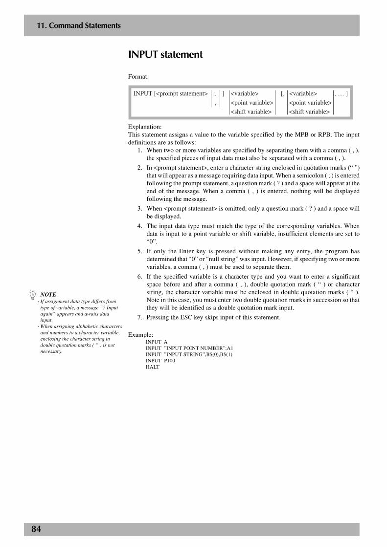
84
2
11. Command Statements
INPUT statement
Format:
INPUT [<prompt statement> ; ] <variable> [, <variable> , … ]
, <point variable> <point variable>
<shift variable> <shift variable>
Explanation:This statement assigns a value to the variable specified by the MPB or RPB. The inputdefinitions are as follows:
1. When two or more variables are specified by separating them with a comma ( , ),the specified pieces of input data must also be separated with a comma ( , ).
2. In <prompt statement>, enter a character string enclosed in quotation marks (“ ”)that will appear as a message requiring data input. When a semicolon ( ; ) is enteredfollowing the prompt statement, a question mark ( ? ) and a space will appear at theend of the message. When a comma ( , ) is entered, nothing will be displayedfollowing the message.
3. When <prompt statement> is omitted, only a question mark ( ? ) and a space willbe displayed.
4. The input data type must match the type of the corresponding variables. Whendata is input to a point variable or shift variable, insufficient elements are set to“0”.
5. If only the Enter key is pressed without making any entry, the program hasdetermined that “0” or “null string” was input. However, if specifying two or morevariables, a comma ( , ) must be used to separate them.
6. If the specified variable is a character type and you want to enter a significantspace before and after a comma ( , ), double quotation mark ( “ ) or characterstring, the character variable must be enclosed in double quotation marks ( “ ).Note in this case, you must enter two double quotation marks in succession so thatthey will be identified as a double quotation mark input.
7. Pressing the ESC key skips input of this statement.
Example:INPUT AINPUT ”INPUT POINT NUMBER”;A1INPUT ”INPUT STRING”,B$(0),B$(1)INPUT P100HALT
n NOTE· If assignment data type differs from
type of variable, a message “? Inputagain” appears and awaits datainput.
· When assigning alphabetic charactersand numbers to a character variable,enclosing the character string indouble quotation marks ( “ ) is notnecessary.
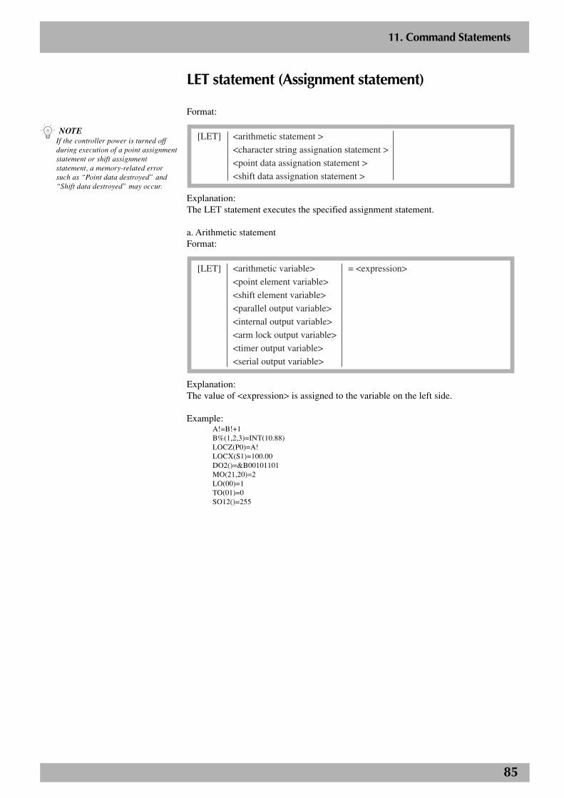
85
2
11. Command Statements
LET statement (Assignment statement)
Format:
[LET] <arithmetic statement >
<character string assignation statement >
<point data assignation statement >
<shift data assignation statement >
Explanation:The LET statement executes the specified assignment statement.
a. Arithmetic statementFormat:
[LET] <arithmetic variable> = <expression>
<point element variable>
<shift element variable>
<parallel output variable>
<internal output variable>
<arm lock output variable>
<timer output variable>
<serial output variable>
Explanation:The value of <expression> is assigned to the variable on the left side.
Example:A!=B!+1B%(1,2,3)=INT(10.88)LOCZ(P0)=A!LOCX(S1)=100.00DO2()=&B00101101MO(21,20)=2LO(00)=1TO(01)=0SO12()=255
n NOTEIf the controller power is turned offduring execution of a point assignmentstatement or shift assignmentstatement, a memory-related errorsuch as “Point data destroyed” and“Shift data destroyed” may occur.
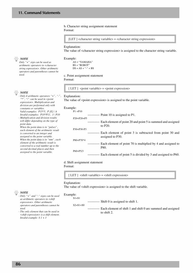
86
2
11. Command Statements
b. Character string assignment statementFormat:
[LET ] <character string variable> = <character string expression>
Explanation:The value of <character string expression> is assigned to the character string variable.
Example:A$ = “YAMAHA”B$ = “ROBOT”D$ = A$ + “-“ + B$
c. Point assignment statementFormat:
[ LET ] <point variable> = <point expression>
Explanation:The value of <point expression> is assigned to the point variable.
Example:P1 =P10
----------- Point 10 is assigned to P1.P20=P20+P5
----------- Each element of point 20 and point 5 is summed and assignedto P20.
P30=P30-P3
----------- Each element of point 3 is subtracted from point 30 andassigned to P30.
P80=P70*4
----------- Each element of point 70 is multiplied by 4 and assigned toP80.
P60=P5/3
----------- Each element of point 5 is divided by 3 and assigned to P60.
d. Shift assignment statementFormat:
[ LET ] <shift variable> = <shift expression>
Explanation:The value of <shift expression> is assigned to the shift variable.
Example:S1=S1
----------- Shift 0 is assigned to shift 1.S2=S1+S0
----------- Each element of shift 1 and shift 0 are summed and assignedto shift 2.
n NOTE· Only 4 arithmetic operators “+”, “-”,
“*”, “/” can be used in <pointexpression>. Multiplication anddivision are performed only withconstants or variables.Valid examples: P15*5, P [E] / AInvalid examples: P10*P11, 3 / P10
· Multiplication and division resultswill differ depending on the type ofpoint data.When the point data is in “pulses”,each element of the arithmetic resultis converted to an integer andassigned to the point variable.When the point data is in “mm”, eachelement of the arithmetic result isconverted to a real number up to thesecond decimal places and thenassigned to the point variable.
n NOTEOnly “+” sign can be used asarithmetic operators in <characterstring expression>. Other arithmeticoperators and parentheses cannot beused.
n NOTE· Only “+” and “-“ signs can be used
as arithmetic operators in <shiftexpression>. Other arithmeticoperators and parentheses cannot beused.
· The only element that can be used in<shift expression> is a shift element.Invalid example: S 1 + 3
87
2
11. Command Statements
LO statement (Arm lock output)
Format:
[ LET ] LO0 ( [b, · · ·, b ] ) = <expression>
LO ( 0b, · · ·, 0b )
b : bit definition 0 to 7The value of <expression> should be an integer or it will be converted to an integer. Thelower bits corresponding to the bits specified on the left side will be valid.
Explanation:This statement outputs the specified value to the LO port to prohibit axis movement orallow axis movement.LO(00) to LO(07) respectively correspond to axes 1 to 8. Axis movement is prohibited inON status.
Example:LO0()=&B00001010
----------- Prohibits movement of axes 2 and 4.LO0(2,1)=&B10
----------- Prohibits movement of axis 3.
Related commands: RESET, SET
n NOTE· This statement can be used for the
axis that starts to move.· Bits must be specified in ascending
order from the right.
88
2
11. Command Statements
MO statement (Internal output)
Format:
[LET ] MOm ( [b, · · ·, b ] ) = <expression>
MO ( mb, · · ·, mb )
m : port number 2 to 7, 10 to 17, 20 to 27b : bit definition 0 to 7The value of <expression> should be an integer or it will be converted to an integer andthe lower bits corresponding to the bits specified on the left side will be valid.
Explanation:This statement outputs the specified value to the MO ports.
Examples:MO2()=&B10111000
----------- MO (27, 25, 24, 23) are turned ON, and MO (26, 22, 21, 20)are turned OFF.
MO2(6,5,1)=&B010
----------- MO (25) is turned ON, and MO (26, 21) are turned OFF.MO3() = 15
----------- MO (33, 32, 31, 30) are turned ON, and MO (37, 36, 35, 34)are turned OFF.
MO(37,35,27,20)=A
----------- The contents of the 4 lower bits obtained when variable A isconverted to an integer are output to MO (37, 35, 27, 20),respectively.
Related commands: RESET, SET
n NOTE· Output to the MO0 ( ) and MO1 ( )
ports is not allowed.· The output status of origin sensors for
axes 1 to 8 (in order from bit 0) isavailable to the MO0 ( ) port. Eachbit sets to “1” when the origin sensorturns ON, and to “0” when OFF.
· The HOLD status of axes 1 to 8 (inorder from bit 0) is output to the MO1( ) port. Each bit sets to “1” when theaxis is in a HOLD status, and to “0”when not. Being in HOLD statusmeans that the axis has alreadyreached the target position.
· Bits must be specified in ascendingorder from the right.
89
2
11. Command Statements
MOVE statement(Absolute position movement command)
Format:
MOVE PTP , <point definition> [, option [, option] … ] P L C
Explanation:This statement executes an absolute movement of main robot axes. This statement willnot move the sub robot axes and auxiliary axes.
Movement type : PTP, linear interpolation, circular interpolationPoint data setting : Direct coordinate data input, point definitionOptions : Speed setting, arch motion setting, STOPON condition
setting, CONT setting, acceleration setting, decelerationsetting, coordinate plane setting, port output setting
Movement type· PTP (point to point) movementPTP movement begins after positioning on all movable axes is complete (within thetolerance range), and the command terminates when all movable axes enter the OUTposition range. All movable axes will reach the target positions simultaneously, but theirpaths are not guaranteed.
Cautions for next command following MOVE P commandIf the next command following the MOVE P command is an executable command such asa signal output command, that next command will start when the movement axis entersthe OUT position range. In other words, that next command starts before the axis arriveswithin the target position tolerance range.Examples:
Signal output (DO, etc.)
DELAY
HALT
HOLD
WAIT
Signal is output when axis enters within OUT position range.
DELAY command is executed and time standby starts, when axis enters within OUT position range.
Program stops and is also reset when axis enters within OUT position range. So axis movement stops.
Program temporarily stops when axis enters within OUT position range. So axis movement stops.
WAIT command is executed when axis enters within OUT position range.
To execute the next command after waiting for the axes to arrive within the target positiontolerance range, use the WAIT ARM statement.
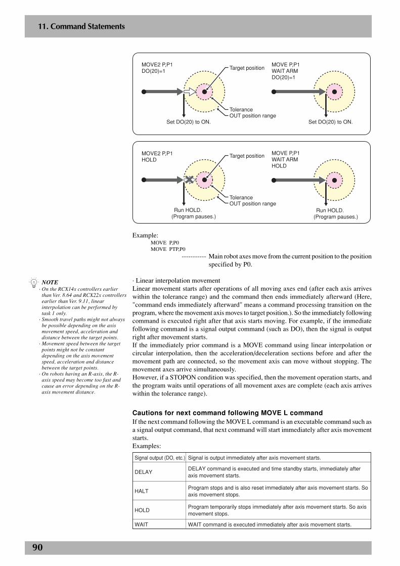
90
2
11. Command Statements
P1
Set DO(20) to ON.
MOVE P,P1WAIT ARMDO(20)=1
Set DO(20) to ON.
MOVE2 P,P1DO(20)=1
Tolerance
Target position
OUT position range
Run HOLD.(Program pauses.)
MOVE P,P1WAIT ARMHOLD
MOVE2 P,P1HOLD
ToleranceOUT position range
Target position
Run HOLD.(Program pauses.)
Example:MOVE P,P0MOVE PTP,P0
----------- Main robot axes move from the current position to the positionspecified by P0.
· Linear interpolation movementLinear movement starts after operations of all moving axes end (after each axis arriveswithin the tolerance range) and the command then ends immediately afterward (Here,"command ends immediately afterward" means a command processing transition on theprogram, where the movement axis moves to target position.). So the immediately followingcommand is executed right after that axis starts moving. For example, if the immediatefollowing command is a signal output command (such as DO), then the signal is outputright after movement starts.If the immediately prior command is a MOVE command using linear interpolation orcircular interpolation, then the acceleration/deceleration sections before and after themovement path are connected, so the movement axis can move without stopping. Themovement axes arrive simultaneously.However, if a STOPON condition was specified, then the movement operation starts, andthe program waits until operations of all movement axes are complete (each axis arriveswithin the tolerance range).
Cautions for next command following MOVE L commandIf the next command following the MOVE L command is an executable command such asa signal output command, that next command will start immediately after axis movementstarts.Examples:
Signal output (DO, etc.)
DELAY
HALT
HOLD
WAIT
Signal is output immediately after axis movement starts.
DELAY command is executed and time standby starts, immediately after axis movement starts.
Program stops and is also reset immediately after axis movement starts. So axis movement stops.
Program temporarily stops immediately after axis movement starts. So axis movement stops.
WAIT command is executed immediately after axis movement starts.
n NOTE· On the RCX14x controllers earlier
than Ver. 8.64 and RCX22x controllersearlier than Ver. 9.11, linearinterpolation can be performed bytask 1 only.
· Smooth travel paths might not alwaysbe possible depending on the axismovement speed, acceleration anddistance between the target points.
· Movement speed between the targetpoints might not be constantdepending on the axis movementspeed, acceleration and distancebetween the target points.
· On robots having an R-axis, the R-axis speed may become too fast andcause an error depending on the R-axis movement distance.
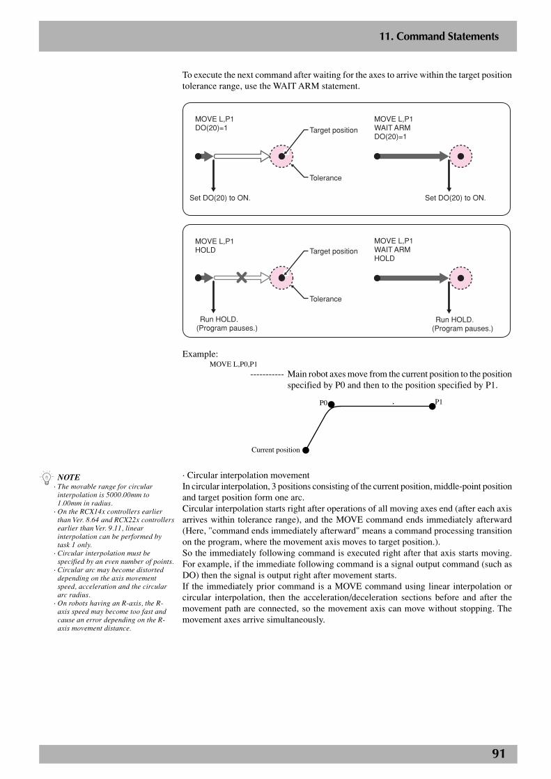
91
2
11. Command Statements
To execute the next command after waiting for the axes to arrive within the target positiontolerance range, use the WAIT ARM statement.
P1
Set DO(20) to ON.
MOVE L,P1WAIT ARMDO(20)=1
Set DO(20) to ON.
MOVE L,P1DO(20)=1
Tolerance
Target position
Run HOLD.(Program pauses.)
MOVE L,P1WAIT ARMHOLD
MOVE L,P1HOLD
Tolerance
Target position
Run HOLD.(Program pauses.)
Example: MOVE L,P0,P1
----------- Main robot axes move from the current position to the positionspecified by P0 and then to the position specified by P1.
P0
Current position
P1
· Circular interpolation movementIn circular interpolation, 3 positions consisting of the current position, middle-point positionand target position form one arc.Circular interpolation starts right after operations of all moving axes end (after each axisarrives within tolerance range), and the MOVE command ends immediately afterward(Here, "command ends immediately afterward" means a command processing transitionon the program, where the movement axis moves to target position.).So the immediately following command is executed right after that axis starts moving.For example, if the immediate following command is a signal output command (such asDO) then the signal is output right after movement starts.If the immediately prior command is a MOVE command using linear interpolation orcircular interpolation, then the acceleration/deceleration sections before and after themovement path are connected, so the movement axis can move without stopping. Themovement axes arrive simultaneously.
n NOTE· The movable range for circular
interpolation is 5000.00mm to1.00mm in radius.
· On the RCX14x controllers earlierthan Ver. 8.64 and RCX22x controllersearlier than Ver. 9.11, linearinterpolation can be performed bytask 1 only.
· Circular interpolation must bespecified by an even number of points.
· Circular arc may become distorteddepending on the axis movementspeed, acceleration and the circulararc radius.
· On robots having an R-axis, the R-axis speed may become too fast andcause an error depending on the R-axis movement distance.

92
2
11. Command Statements
Cautions for next command following MOVE C commandIf the next command following the MOVE C command is an executable command suchas a signal output command, that next command will start immediately after axis movementstarts.Examples:
Signal output (DO, etc.)
DELAY
HALT
HOLD
WAIT
Signal is output when axis enters within OUT position range.
DELAY command is executed and time standby starts, when axis enters within OUT position range.
Program stops and is also reset when axis enters within OUT position range. So axis movement stops.
Program temporarily stops when axis enters within OUT position range. So axis movement stops.
WAIT command is executed when axis enters within OUT position range.
To execute the next command after waiting for the axes to arrive within the target positiontolerance range, use the WAIT ARM statement.
P1
Set DO(20) to ON.
MOVE C,P1,P2WAIT ARMDO(20)=1
Set DO(20) to ON.
MOVE C,P1,P2DO(20)=1
Tolerance
Target position
Run HOLD.(Program pauses.)
MOVE C,P1,P2WAIT ARMHOLD
MOVE C,P1,P2HOLD
Tolerance
Target position
Run HOLD.(Program pauses.)
Example:MOVE L,P20MOVE C,P21,P22,P23,P20MOVE L,P24
----------- Moves linearly from the current position to P20, then movesalong a circle formed by points P20, P21, P22, P23 and P20,and moves again linearly to P24.
P23
Current position P24
P22
P21
P20
93
2
11. Command Statements
Point data setting· Direct coordinate data inputFormat:
X Y Z R A B
X, Y, Z, R, A and B are coordinate values on respective axes and must be separated fromeach other by a space.
Explanation:Directly specify the coordinate data on each axis with an integer or a real number. Whenthe coordinate data is an integer, the movement units are viewed as “pulses”. When thecoordinate data is a real number, the units are viewed as “mm” or “deg”.PTP movement and linear interpolation movement can be used with this coordinate datasetting.
Hand system flags can be specified when directly specifying the coordinate data in "mm"units for SCARA robots.When setting an extended hand system flag for SCARA robots, set either 1 or 2 at the dataend of B. If a number other than 1 or 2 is set, or if no number is designated, then 0 will beset to indicate that there is no hand system flag.
1 : Right-handed system is used to move to a specified position.
2 : Left-handed system is used to move to a specified position.
Example:MOVE P,10000 10000 1000 1000 0 0
----------- Moves by PTP from the current position to the specifiedpositions.
· Point definitionFormat:
<point expression> [, <point expression> …]
Explanation:Specify the point data in <point expression>. Two or more pieces of data can be designatedby separating them with a comma ( , ).
Example: MOVE P,P1
----------- Moves from the current position to the position specified byP1.
MOVE P,P20,P0,P100
----------- Moves in order from the current position to the positionsspecified by P20, P0 and P100.
n NOTE· Circular interpolation must be
specified by an even number of points.· When a SCARA robot is used and a
hand system flag is set for the pointdata you specify, that hand system haspriority over the current arm type.
c CAUTIONWhen moving the robot by linear orcircular interpolation to a pointwhere a hand system flag is specified,make sure that the same hand systemis used at the current position andtarget position. If the same handsystem is not used, then an error willoccur and robot movement will not beallowed.
n NOTE· When a SCARA robot is used and a
hand system flag is set for the targetposition data, that hand system haspriority over the current arm type.
· Hand system flags are only availablefrom software version 8.08 onwards.
c CAUTIONWhen performing linear interpolationwhile specifying a hand system flag,make sure that the same hand systemis used at the current position andtarget position. If the same handsystem is not used, then an error willoccur and robot movement will not beallowed.
n NOTEIf point data is specified with bothintegers and real numbers in the samestatement, all axes move in “mm” or“deg” units.
94
2
11. Command Statements
Option types· Speed settingFormat 1:
SPEED = <expression>
S
The value of <expression> must be from 1 to 100. (Unit: %)
Explanation:Specify the program speed in <expression>. Robot operating speed is determined by theproduct of the automatic movement speed and the program speed. This option is enabledonly for the specified MOVE statement.
Example:MOVE P,P10,S=10
----------- Moves from the current position to the position specified byP10 using a program speed of 10%.
Format 2:
VEL = <expression>
The value of <expression> must be from 1 to 750 for SCARA robots, and from 1 to 1000for Cartesian robots. (Unit: mm/sec)
Explanation:Specify the maximum composite speed of the XYZ axes in <expression> in "mm/sec"units. This option can be used for linear interpolation and circular interpolation movementsof SCARA robots or Cartesian robots and is enabled only for the specified MOVEstatement.
Example:MOVE L,P10,VEL=100
----------- Moves at a maximum XYZ composite speed of 100mm/secfrom the current position to the position specified by P10.
· Arch motion settingFormat:
x = <expression>, [ x = <expression> … ]
x : Axis X, Y, Z, R, A or B
When the value of <expression> is an integer, the movement units are viewed as “pulses”.When the value is a real number containing a decimal point, the units are viewed as “mm”or “deg”.
Explanation:The specified “x” axis first moves toward the position specified in <expression>. Then,when the specified “x” axis enters the arch position range, all axes other than the “x” axismove toward the target position. Finally, all axes other than the “x” axis enter the archposition range and also the specified “x” axis enters within the tolerance range of theposition specified in <expression>, the specified “x” axis moves toward the target position,and when it enters the OUT position range, the command terminates.This option can be used for PTP movement.If the specified “x” axes include an X-axis or Y-axis, the target position and the<expression> must be specified by an integer (in “pulse” units).
n NOTEThis option merely specifies themaximum composite speed and doesnot guarantee the specified speed.
n NOTEThis option merely specifies themaximum speed and does notguarantee the specified speed.
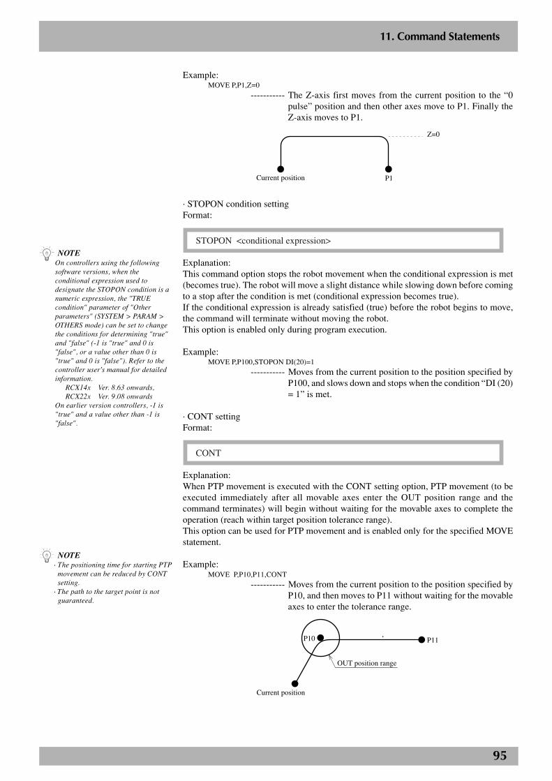
95
2
11. Command Statements
Example:MOVE P,P1,Z=0
----------- The Z-axis first moves from the current position to the “0pulse” position and then other axes move to P1. Finally theZ-axis moves to P1.
P1Current position
Z=0
· STOPON condition settingFormat:
STOPON <conditional expression>
Explanation:This command option stops the robot movement when the conditional expression is met(becomes true). The robot will move a slight distance while slowing down before comingto a stop after the condition is met (conditional expression becomes true).If the conditional expression is already satisfied (true) before the robot begins to move,the command will terminate without moving the robot.This option is enabled only during program execution.
Example:MOVE P,P100,STOPON DI(20)=1
----------- Moves from the current position to the position specified byP100, and slows down and stops when the condition “DI (20)= 1” is met.
· CONT settingFormat:
CONT
Explanation:When PTP movement is executed with the CONT setting option, PTP movement (to beexecuted immediately after all movable axes enter the OUT position range and thecommand terminates) will begin without waiting for the movable axes to complete theoperation (reach within target position tolerance range).This option can be used for PTP movement and is enabled only for the specified MOVEstatement.
Example:MOVE P,P10,P11,CONT
----------- Moves from the current position to the position specified byP10, and then moves to P11 without waiting for the movableaxes to enter the tolerance range.
P10
Current position
P11
OUT position range
n NOTE· The positioning time for starting PTP
movement can be reduced by CONTsetting.
· The path to the target point is notguaranteed.
n NOTEOn controllers using the followingsoftware versions, when theconditional expression used todesignate the STOPON condition is anumeric expression, the "TRUEcondition" parameter of "Otherparameters" (SYSTEM > PARAM >OTHERS mode) can be set to changethe conditions for determining "true"and "false" (-1 is "true" and 0 is"false", or a value other than 0 is"true" and 0 is "false"). Refer to thecontroller user's manual for detailedinformation.
RCX14x Ver. 8.63 onwards,RCX22x Ver. 9.08 onwards
On earlier version controllers, -1 is"true" and a value other than -1 is"false".
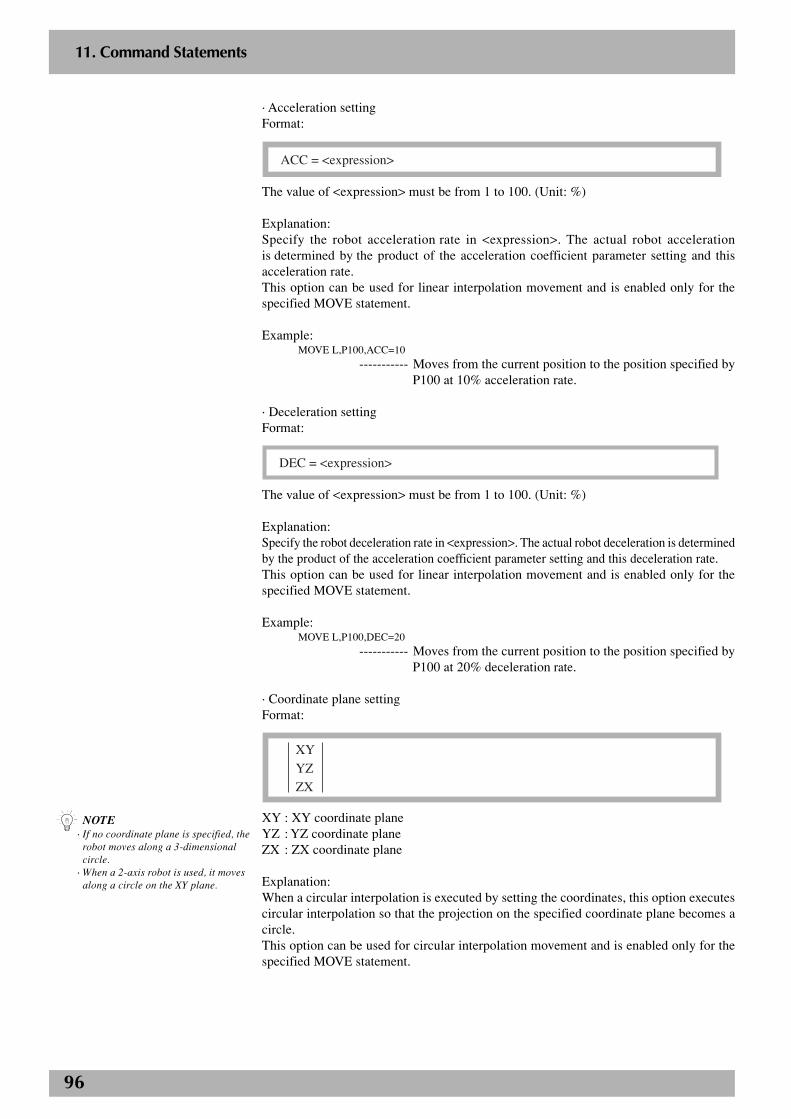
96
2
11. Command Statements
· Acceleration settingFormat:
ACC = <expression>
The value of <expression> must be from 1 to 100. (Unit: %)
Explanation:Specify the robot acceleration rate in <expression>. The actual robot accelerationis determined by the product of the acceleration coefficient parameter setting and thisacceleration rate.This option can be used for linear interpolation movement and is enabled only for thespecified MOVE statement.
Example:MOVE L,P100,ACC=10
----------- Moves from the current position to the position specified byP100 at 10% acceleration rate.
· Deceleration settingFormat:
DEC = <expression>
The value of <expression> must be from 1 to 100. (Unit: %)
Explanation:Specify the robot deceleration rate in <expression>. The actual robot deceleration is determinedby the product of the acceleration coefficient parameter setting and this deceleration rate.This option can be used for linear interpolation movement and is enabled only for thespecified MOVE statement.
Example:MOVE L,P100,DEC=20
----------- Moves from the current position to the position specified byP100 at 20% deceleration rate.
· Coordinate plane settingFormat:
XY
YZ
ZX
XY : XY coordinate planeYZ : YZ coordinate planeZX : ZX coordinate plane
Explanation:When a circular interpolation is executed by setting the coordinates, this option executescircular interpolation so that the projection on the specified coordinate plane becomes acircle.This option can be used for circular interpolation movement and is enabled only for thespecified MOVE statement.
n NOTE· If no coordinate plane is specified, the
robot moves along a 3-dimensionalcircle.
· When a 2-axis robot is used, it movesalong a circle on the XY plane.
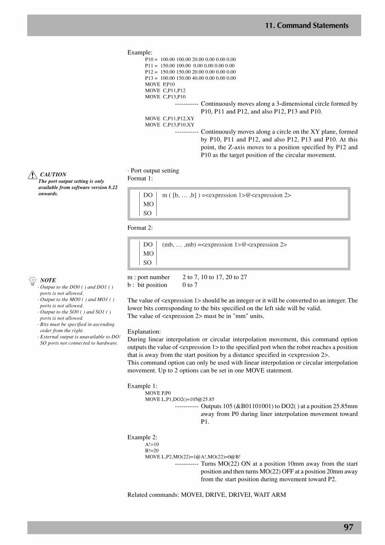
97
2
11. Command Statements
Example:P10 = 100.00 100.00 20.00 0.00 0.00 0.00P11 = 150.00 100.00 0.00 0.00 0.00 0.00P12 = 150.00 150.00 20.00 0.00 0.00 0.00P13 = 100.00 150.00 40.00 0.00 0.00 0.00MOVE P,P10MOVE C,P11,P12MOVE C,P13,P10
----------- Continuously moves along a 3-dimensional circle formed byP10, P11 and P12, and also P12, P13 and P10.
MOVE C,P11,P12,XYMOVE C,P13,P10,XY
----------- Continuously moves along a circle on the XY plane, formedby P10, P11 and P12, and also P12, P13 and P10. At thispoint, the Z-axis moves to a position specified by P12 andP10 as the target position of the circular movement.
· Port output settingFormat 1:
DO m ( [b, … ,b] ) =<expression 1>@<expression 2>
MO
SO
Format 2:
DO (mb, … ,mb) =<expression 1>@<expression 2>
MO
SO
m : port number 2 to 7, 10 to 17, 20 to 27b : bit position 0 to 7
The value of <expression 1> should be an integer or it will be converted to an integer. Thelower bits corresponding to the bits specified on the left side will be valid.The value of <expression 2> must be in "mm" units.
Explanation:During linear interpolation or circular interpolation movement, this command optionoutputs the value of <expression 1> to the specified port when the robot reaches a positionthat is away from the start position by a distance specified in <expression 2>.This command option can only be used with linear interpolation or circular interpolationmovement. Up to 2 options can be set in one MOVE statement.
Example 1:MOVE P,P0MOVE L,P1,DO2()[email protected]
----------- Outputs 105 (&B01101001) to DO2( ) at a position 25.85mmaway from P0 during liner interpolation movement towardP1.
Example 2:A!=10B!=20MOVE L,P2,MO(22)=1@A!,MO(22)=0@B!
----------- Turns MO(22) ON at a position 10mm away from the startposition and then turns MO(22) OFF at a position 20mm awayfrom the start position during movement toward P2.
Related commands: MOVEI, DRIVE, DRIVEI, WAIT ARM
c CAUTIONThe port output setting is onlyavailable from software version 8.22onwards.
n NOTE· Output to the DO0 ( ) and DO1 ( )
ports is not allowed.· Output to the MO0 ( ) and MO1 ( )
ports is not allowed.· Output to the SO0 ( ) and SO1 ( )
ports is not allowed.· Bits must be specified in ascending
order from the right.· External output is unavailable to DO/
SO ports not connected to hardware.

98
2
11. Command Statements
MOVE2 statement(Absolute position movement command)
Format:
MOVE2 PTP , <point definition> [, option [, option] … ] P L C
Explanation:This statement executes an absolute movement of all sub robot axes. This statement willnot move the main robot axes and auxiliary axes.
Movement type : PTP, linear interpolation, circular interpolationPoint data setting : Direct coordinate data input, point definitionOptions : Speed setting, arch motion setting, STOPON condition
setting, CONT setting, acceleration setting, deceleration set-ting, coordinate plane setting, port output setting
Movement type· PTP (point to point) movementPTP movement begins after positioning on all movable axes is complete (within thetolerance range), and the command terminates when all movable axes enter the OUTposition range. All movable axes will reach the target positions simultaneously, but theirpaths are not guaranteed.
Cautions for next command following MOVE2 P commandIf the next command following the MOVE2 P command is an executable command suchas a signal output command, that next command will start when the movement axis entersthe OUT position range. In other words, that next command starts before the axis arriveswithin the target position tolerance range.Examples:
Signal output (DO, etc.)
DELAY
HALT
HOLD
WAIT
Signal is output when axis enters within OUT position range.
DELAY command is executed and time standby starts, when axis enters within OUT position range.
Program stops and is also reset when axis enters within OUT position range. So axis movement stops.
Program temporarily stops when axis enters within OUT position range. So axis movement stops.
WAIT command is executed when axis enters within OUT position range.
To execute the next command after waiting for the axes to arrive within the target positiontolerance range, use the WAIT ARM2 statement.
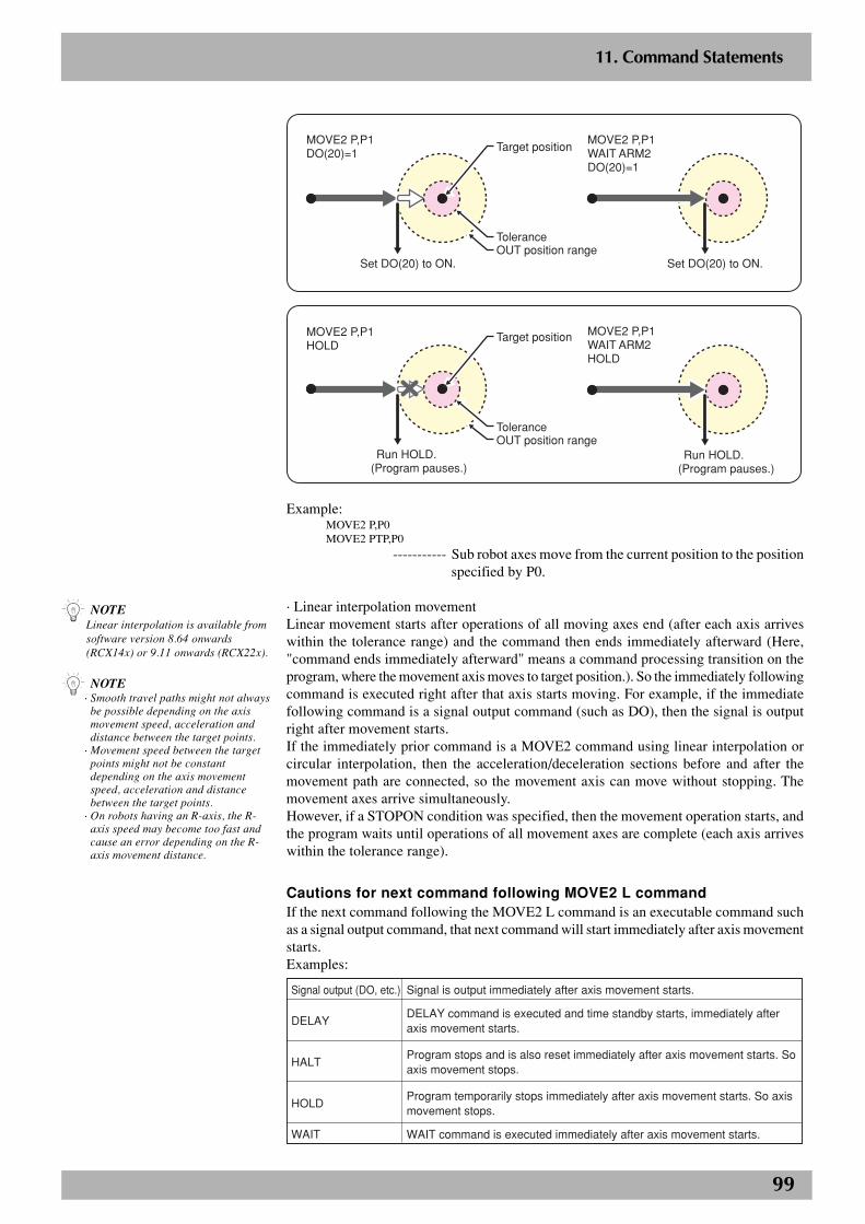
99
2
11. Command Statements
P1
Set DO(20) to ON.
MOVE2 P,P1WAIT ARM2DO(20)=1
Set DO(20) to ON.
MOVE2 P,P1DO(20)=1
Tolerance
Target position
OUT position range
Run HOLD.(Program pauses.)
MOVE2 P,P1WAIT ARM2HOLD
MOVE2 P,P1HOLD
ToleranceOUT position range
Target position
Run HOLD.(Program pauses.)
Example:MOVE2 P,P0MOVE2 PTP,P0
----------- Sub robot axes move from the current position to the positionspecified by P0.
· Linear interpolation movementLinear movement starts after operations of all moving axes end (after each axis arriveswithin the tolerance range) and the command then ends immediately afterward (Here,"command ends immediately afterward" means a command processing transition on theprogram, where the movement axis moves to target position.). So the immediately followingcommand is executed right after that axis starts moving. For example, if the immediatefollowing command is a signal output command (such as DO), then the signal is outputright after movement starts.If the immediately prior command is a MOVE2 command using linear interpolation orcircular interpolation, then the acceleration/deceleration sections before and after themovement path are connected, so the movement axis can move without stopping. Themovement axes arrive simultaneously.However, if a STOPON condition was specified, then the movement operation starts, andthe program waits until operations of all movement axes are complete (each axis arriveswithin the tolerance range).
Cautions for next command following MOVE2 L commandIf the next command following the MOVE2 L command is an executable command suchas a signal output command, that next command will start immediately after axis movementstarts.Examples:
Signal output (DO, etc.)
DELAY
HALT
HOLD
WAIT
Signal is output immediately after axis movement starts.
DELAY command is executed and time standby starts, immediately after axis movement starts.
Program stops and is also reset immediately after axis movement starts. So axis movement stops.
Program temporarily stops immediately after axis movement starts. So axis movement stops.
WAIT command is executed immediately after axis movement starts.
n NOTELinear interpolation is available fromsoftware version 8.64 onwards(RCX14x) or 9.11 onwards (RCX22x).
n NOTE· Smooth travel paths might not always
be possible depending on the axismovement speed, acceleration anddistance between the target points.
· Movement speed between the targetpoints might not be constantdepending on the axis movementspeed, acceleration and distancebetween the target points.
· On robots having an R-axis, the R-axis speed may become too fast andcause an error depending on the R-axis movement distance.
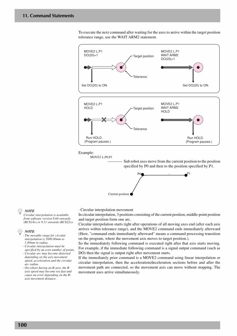
100
2
11. Command Statements
To execute the next command after waiting for the axes to arrive within the target positiontolerance range, use the WAIT ARM2 statement.
P1
Set DO(20) to ON.
MOVE2 L,P1WAIT ARM2DO(20)=1
Set DO(20) to ON.
MOVE2 L,P1DO(20)=1
Tolerance
Target position
Run HOLD.(Program pauses.)
MOVE2 L,P1WAIT ARM2HOLD
MOVE2 L,P1HOLD
Tolerance
Target position
Run HOLD.(Program pauses.)
Example: MOVE2 L,P0,P1
----------- Sub robot axes move from the current position to the positionspecified by P0 and then to the position specified by P1.
P0
Current position
P1
· Circular interpolation movementIn circular interpolation, 3 positions consisting of the current position, middle-point positionand target position form one arc.Circular interpolation starts right after operations of all moving axes end (after each axisarrives within tolerance range), and the MOVE2 command ends immediately afterward(Here, "command ends immediately afterward" means a command processing transitionon the program, where the movement axis moves to target position.).So the immediately following command is executed right after that axis starts moving.For example, if the immediate following command is a signal output command (such asDO) then the signal is output right after movement starts.If the immediately prior command is a MOVE2 command using linear interpolation orcircular interpolation, then the acceleration/deceleration sections before and after themovement path are connected, so the movement axis can move without stopping. Themovement axes arrive simultaneously.
n NOTE· The movable range for circular
interpolation is 5000.00mm to1.00mm in radius.
· Circular interpolation must bespecified by an even number of points.
· Circular arc may become distorteddepending on the axis movementspeed, acceleration and the circulararc radius.
· On robots having an R-axis, the R-axis speed may become too fast andcause an error depending on the R-axis movement distance.
n NOTECircular interpolation is availablefrom software version 8.64 onwards(RCX14x) or 9.11 onwards (RCX22x).

101
2
11. Command Statements
Cautions for next command following MOVE2 C commandIf the next command following the MOVE2 C command is an executable command suchas a signal output command, that next command will start immediately after axis movementstarts.Examples:
Signal output (DO, etc.)
DELAY
HALT
HOLD
WAIT
Signal is output when axis enters within OUT position range.
DELAY command is executed and time standby starts, when axis enters within OUT position range.
Program stops and is also reset when axis enters within OUT position range. So axis movement stops.
Program temporarily stops when axis enters within OUT position range. So axis movement stops.
WAIT command is executed when axis enters within OUT position range.
To execute the next command after waiting for the axes to arrive within the target positiontolerance range, use the WAIT ARM2 statement.
P1
Set DO(20) to ON.
MOVE2 C,P1,P2WAIT ARM2DO(20)=1
Set DO(20) to ON.
MOVE2 C,P1,P2DO(20)=1
Tolerance
Target position
Run HOLD.(Program pauses.)
MOVE2 C,P1,P2WAIT ARM2HOLD
MOVE2 C,P1,P2HOLD
Tolerance
Target position
Run HOLD.(Program pauses.)
Example:MOVE2 L,P20MOVE2 C,P21,P22,P23,P20MOVE2 L,P24
----------- Moves linearly from the current position to P20, then movesalong a circle formed by points P20, P21, P22, P23 and P20,and moves again linearly to P24.
P23
Current position P24
P22
P21
P20
102
2
11. Command Statements
Point data setting· Direct coordinate data inputFormat:
X Y Z R A B
X, Y, Z, R, A and B are the coordinate values on respective axes, and must be separatedfrom each other by a space.
Explanation:Directly specify the coordinate data on each axis with an integer or a real number. Whenthe coordinate data is an integer, the movement units are viewed as “pulses”. When thecoordinate data is a real number, the units are viewed as “mm” or “deg”.PTP movement and linear interpolation movement can be used with this coordinate datasetting.
Hand system flags can be specified when directly specifying the coordinate data in "mm"units for SCARA robots.When setting an extended hand system flag for SCARA robots, set either 1 or 2 at the dataend of B. If a number other than 1 or 2 is set, or if no number is designated, then 0 will beset to indicate that there is no hand system flag.
1 : Right-handed system is used to move to a specified position.
2 : Left-handed system is used to move to a specified position.
Example: MOVE2 P,10000 10000 1000 1000 0 0
----------- Moves by PTP from the current position to the specifiedpositions.
· Point definitionFormat:
<point expression> [, <point expression> …]
Explanation:Specify the point data in <point expression>. Two or more pieces of data can be designatedby separating them with a comma ( , ).
Example:MOVE2 P,P1
----------- Moves from the current position to the position specified byP1.
MOVE2 P,P20,P0,P100
----------- Moves in order from the current position to the positionsspecified by P20, P0 and P100.
n NOTE· Circular interpolation must be
specified by an even number of points.· When a SCARA robot is used and a
hand system flag is set for the pointdata you specify, that hand system haspriority over the current arm type.
c CAUTIONWhen moving the robot by linear orcircular interpolation to a pointwhere a hand system flag is specified,make sure that the same hand systemis used at the current position andtarget position. If the same handsystem is not used, then an error willoccur and robot movement will not beallowed.
n NOTE· When a SCARA robot is used and a
hand system flag is set for the targetposition data, that hand system haspriority over the current arm type.
· Hand system flags are only availablefrom software version 8.08 onwards.
c CAUTIONWhen performing linear interpolationwhile specifying a hand system flag,make sure that the same hand systemis used at the current position andtarget position. If the same handsystem is not used, then an error willoccur and robot movement will not beallowed.
n NOTEIf point data is specified with bothintegers and real numbers in the samestatement, all axes move in “mm” or“deg” units.
103
2
11. Command Statements
Option types· Speed settingFormat 1:
SPEED = <expression>
S
The value of <expression> must be from 1 to 100. (Unit: %)
Explanation:Specify the program speed in <expression>. Robot operating speed is determined by theproduct of the automatic movement speed and the program speed. This option is enabledonly for the specified MOVE2 statement.
Example:MOVE2 P,P10,S=10
----------- Moves from the current position to the position specified byP10 using a program speed of 10%.
Format 2:
VEL = <expression>
The value of <expression> must be from 1 to 750 for SCARA robots, and from 1 to 1000for Cartesian robots. (Unit: mm/sec)
Explanation:Specify the maximum composite speed of the XYZ axes in <expression> in "mm/sec"units. This option can be used for linear interpolation and circular interpolation move-ments of SCARA robots or Cartesian robots and is enabled only for the specified MOVE2statement.
Example:MOVE2 L,P10,VEL=100
----------- Moves at a maximum XYZ composite speed of 100mm/secfrom the current position to the position specified by P10.
· Arch motion settingFormat:
x = <expression>, [ x = <expression> … ]
x : Axis X, Y, Z, R, A or B
When the value of <expression> is an integer, the movement units are viewed as “pulses”.When the value is a real number containing a decimal point, the units are viewed as “mm”or “deg”.
Explanation:The specified “x” axis first moves toward the position specified in <expression>. Then,when the specified “x” axis enters the arch position range, all axes other than the “x” axismove toward the target position. Finally, all axes other than the “x” axis enter the archposition range and also the specified “x” axis enters within the tolerance range of theposition specified in <expression>, the specified “x” axis moves toward the target position,and when it enters the OUT position range, the command terminates.This option can be used for PTP movement.If the specified “x” axes include an X-axis or Y-axis, the target position and the<expression> must be specified by an integer (in “pulse” units).
n NOTEThis option merely specifies themaximum composite speed and doesnot guarantee the specified speed.
n NOTEThis option merely specifies themaximum speed and does notguarantee the specified speed.
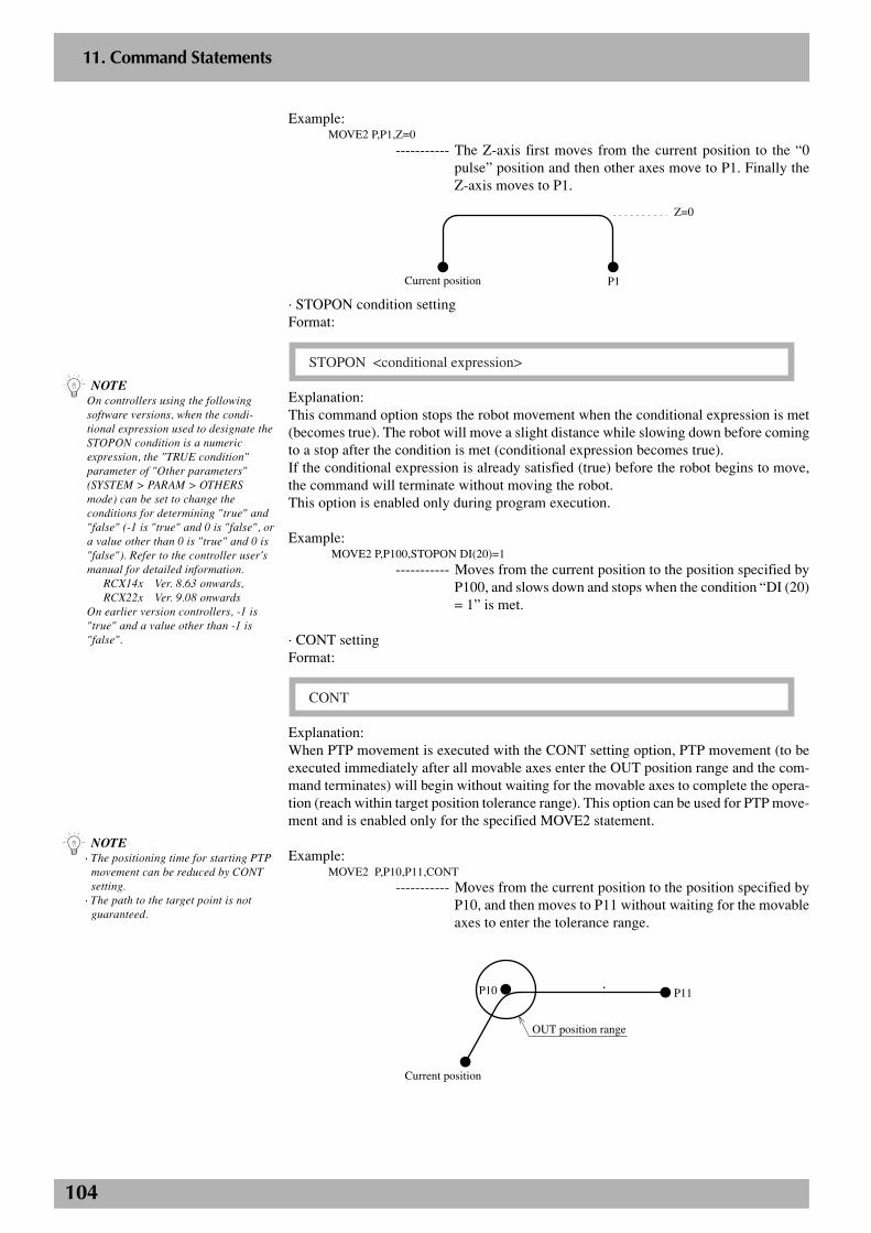
104
2
11. Command Statements
Example:MOVE2 P,P1,Z=0
----------- The Z-axis first moves from the current position to the “0pulse” position and then other axes move to P1. Finally theZ-axis moves to P1.
P1Current position
Z=0
· STOPON condition settingFormat:
STOPON <conditional expression>
Explanation:This command option stops the robot movement when the conditional expression is met(becomes true). The robot will move a slight distance while slowing down before comingto a stop after the condition is met (conditional expression becomes true).If the conditional expression is already satisfied (true) before the robot begins to move,the command will terminate without moving the robot.This option is enabled only during program execution.
Example: MOVE2 P,P100,STOPON DI(20)=1
----------- Moves from the current position to the position specified byP100, and slows down and stops when the condition “DI (20)= 1” is met.
· CONT settingFormat:
CONT
Explanation:When PTP movement is executed with the CONT setting option, PTP movement (to beexecuted immediately after all movable axes enter the OUT position range and the com-mand terminates) will begin without waiting for the movable axes to complete the opera-tion (reach within target position tolerance range). This option can be used for PTP move-ment and is enabled only for the specified MOVE2 statement.
Example:MOVE2 P,P10,P11,CONT
----------- Moves from the current position to the position specified byP10, and then moves to P11 without waiting for the movableaxes to enter the tolerance range.
P10
Current position
P11
OUT position range
n NOTE· The positioning time for starting PTP
movement can be reduced by CONTsetting.
· The path to the target point is notguaranteed.
n NOTEOn controllers using the followingsoftware versions, when the condi-tional expression used to designate theSTOPON condition is a numericexpression, the "TRUE condition"parameter of "Other parameters"(SYSTEM > PARAM > OTHERSmode) can be set to change theconditions for determining "true" and"false" (-1 is "true" and 0 is "false", ora value other than 0 is "true" and 0 is"false"). Refer to the controller user'smanual for detailed information.
RCX14x Ver. 8.63 onwards,RCX22x Ver. 9.08 onwards
On earlier version controllers, -1 is"true" and a value other than -1 is"false".
105
2
11. Command Statements
· Acceleration settingFormat:
ACC = <expression>
The value of <expression> must be from 1 to 100. (Unit: %)
Explanation:Specify the robot acceleration rate in <expression>. The actual robot accelerationis determined by the product of the acceleration coefficient parameter setting and thisacceleration rate.This option can be used for linear interpolation movement and is enabled only for thespecified MOVE2 statement.
Example:MOVE2 L,P100,ACC=10
----------- Moves from the current position to the position specified byP100 at 10% acceleration rate.
· Deceleration settingFormat:
DEC = <expression>
The value of <expression> must be from 1 to 100. (Unit: %)
Explanation:Specify the robot deceleration rate in <expression>. The actual robot deceleration is deter-mined by the product of the acceleration coefficient parameter setting and this decelerationrate.This option can be used for linear interpolation movement and is enabled only for thespecified MOVE2 statement.
Example:MOVE2 L,P100,DEC=20
----------- Moves from the current position to the position specified byP100 at 20% deceleration rate.
· Coordinate plane settingFormat:
XY
YZ
ZX
XY : XY coordinate planeYZ : YZ coordinate planeZX : ZX coordinate plane
Explanation:When a circular interpolation is executed by setting the coordinates, this option executescircular interpolation so that the projection on the specified coordinate plane becomes acircle.This option can be used for circular interpolation movement and is enabled only for thespecified MOVE2 statement.
n NOTE· If no coordinate plane is specified, the
robot moves along a 3-dimensionalcircle.
· When a 2-axis robot is used, it movesalong a circle on the XY plane.
106
2
11. Command Statements
Example:P10 = 100.00 100.00 20.00 0.00 0.00 0.00P11 = 150.00 100.00 0.00 0.00 0.00 0.00P12 = 150.00 150.00 20.00 0.00 0.00 0.00P13 = 100.00 150.00 40.00 0.00 0.00 0.00MOVE2 P,P10MOVE2 C,P11,P12MOVE2 C,P13,P10
----------- Continuously moves along a 3-dimensional circle formed byP10, P11 and P12, and also P12, P13 and P10.
MOVE2 C,P11,P12,XYMOVE2 C,P13,P10,XY
----------- Continuously moves along a circle on the XY plane, formedby P10, P11 and P12, and also P12, P13 and P10. At thispoint, the Z-axis moves to a position specified by P12 andP10 as the target position of the circular movement.
· Port output settingFormat 1:
DO m ( [b, … ,b] ) =<expression 1>@<expression 2>
MO
SO
Format 2:
DO (mb, … ,mb) =<expression 1>@<expression 2>
MO
SO
m : port number 2 to 7, 10 to 17, 20 to 27b : bit position 0 to 7
The value of <expression 1> should be an integer or it will be converted to an integer. Thelower bits corresponding to the bits specified on the left side will be valid.The value of <expression 2> must be in "mm" units.
Explanation:During linear interpolation or circular interpolation movement, this command option out-puts the value of <expression 1> to the specified port when the robot reaches a positionthat is away from the start position by a distance specified in <expression 2>.This command option can only be used with linear interpolation or circular interpolationmovement. Up to 2 options can be set in one MOVE2 statement.
Example 1:MOVE2 P,P0MOVE2 L,P1,DO2()[email protected]
----------- Outputs 105 (&B01101001) to DO2( ) at a position 25.85mmaway from P0 during liner interpolation movement towardP1.
Example 2:A!=10B!=20MOVE2 L,P2,MO(22)=1@A!,MO(22)=0@B!
----------- Turns MO(22) ON at a position 10mm away from the startposition and then turns MO(22) OFF at a position 20mm awayfrom the start position during movement toward P2.
Related commands: MOVEI2, DRIVE2, DRIVEI2, WAIT ARM2
n NOTE· Output to the DO0 ( ) and DO1 ( )
ports is not allowed.· Output to the MO0 ( ) and MO1 ( )
ports is not allowed.· Output to the SO0 ( ) and SO1 ( )
ports is not allowed.· Bits must be specified in ascending
order from the right.· External output is unavailable to DO/
SO ports not connected to hardware.
107
2
11. Command Statements
MOVEI statement(Relative position movement command)
Format:
MOVEI PTP , <point definition> [, option [, option] … ]
P
Explanation:This statement executes a relative movement of all main robot axes. This statement willnot move the sub robot axes and auxiliary axes.
Movement type : PTPPoint data setting : Direct coordinate data input, point definitionOptions : Speed setting
Movement type· PTP (point to point) movementPTP movement begins after positioning on all movable axes is complete (within thetolerance range), and the command then terminates when all movable axes enter the OUTposition range. All movable axes will reach the target positions simultaneously, but theirpaths are not guaranteed.
Cautions for next command following MOVEI commandIf the next command following the MOVEI command is an executable command such asa signal output command, that next command will start when the movement axis entersthe OUT position range. In other words, that next command starts before the axis arriveswithin the target position tolerance range.Examples:
Signal output (DO, etc.)
DELAY
HALT
HOLD
WAIT
Signal is output when axis enters within OUT position range.
DELAY command is executed and time standby starts, when axis enters within OUT position range.
Program stops and is also reset when axis enters within OUT position range. So axis movement stops.
Program temporarily stops when axis enters within OUT position range. So axis movement stops.
WAIT command is executed when axis enters within OUT position range.
To execute the next command after waiting for the axes to arrive within the target positiontolerance range, use the WAIT ARM statement.
n NOTE• If the MOVEI statement is interrupted
and then re-executed in the controllerversions shown below, the resumedmotion can occur either to theoriginal target position, or to a newtarget position referenced to thecurrent position (stop position), inaccordance with the "MOVEI/DRIVEIstart position" setting selected at theother parameters.For details, refer to the controlleruser's manual.
RCX14x Ver. 8.66 onwardsRCX22x Ver. 9.13 onwards
• The other parameters default"MOVEI/DRIVEI start position"setting is Keep (motion to the originaltarget position when MOVEI isinterrupted and then re-executed).
• In controller versions prior to thoseshown above, motion occurs to a newtarget position referenced to thecurrent position when MOVEI isinterrupted and then re-executed.
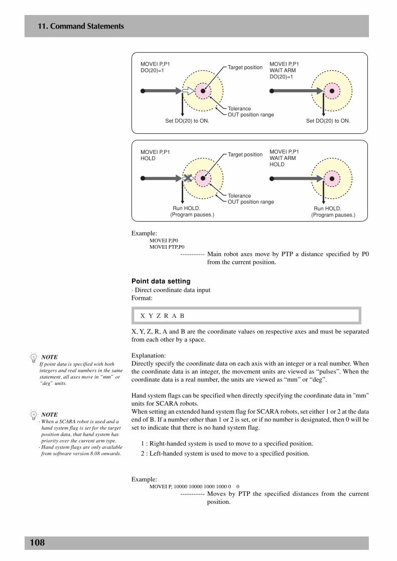
108
2
11. Command Statements
P1
Set DO(20) to ON.
MOVEI P,P1WAIT ARMDO(20)=1
Set DO(20) to ON.
MOVEI P,P1DO(20)=1
Tolerance
Target position
OUT position range
Run HOLD.(Program pauses.)
MOVEI P,P1WAIT ARMHOLD
MOVEI P,P1HOLD
ToleranceOUT position range
Target position
Run HOLD.(Program pauses.)
Example:MOVEI P,P0MOVEI PTP,P0
----------- Main robot axes move by PTP a distance specified by P0from the current position.
Point data setting· Direct coordinate data inputFormat:
X Y Z R A B
X, Y, Z, R, A and B are the coordinate values on respective axes and must be separatedfrom each other by a space.
Explanation:Directly specify the coordinate data on each axis with an integer or a real number. Whenthe coordinate data is an integer, the movement units are viewed as “pulses”. When thecoordinate data is a real number, the units are viewed as “mm” or “deg”.
Hand system flags can be specified when directly specifying the coordinate data in "mm"units for SCARA robots.When setting an extended hand system flag for SCARA robots, set either 1 or 2 at the dataend of B. If a number other than 1 or 2 is set, or if no number is designated, then 0 will beset to indicate that there is no hand system flag.
1 : Right-handed system is used to move to a specified position.
2 : Left-handed system is used to move to a specified position.
Example:MOVEI P, 10000 10000 1000 1000 0 0
----------- Moves by PTP the specified distances from the currentposition.
n NOTE· When a SCARA robot is used and a
hand system flag is set for the targetposition data, that hand system haspriority over the current arm type.
· Hand system flags are only availablefrom software version 8.08 onwards.
n NOTEIf point data is specified with bothintegers and real numbers in the samestatement, all axes move in “mm” or“deg” units.
109
2
11. Command Statements
· Point definitionFormat:
<point expression> [, <point expression> …]
Explanation:Specify the point data in <point expression>. Two or more pieces of data can be designatedby separating them with a comma ( , ).
Example: MOVEI P,P1
----------- Moves by PTP a distance specified by P1 from the currentposition.
Option type· Speed settingFormat 1:
SPEED = <expression>
S
The value of <expression> must be from 1 to 100. (Unit: %)
Explanation:Specify the program speed in <expression>. Robot operating speed is determined by theproduct of the automatic movement speed and the program speed. This option is enabledonly for the specified MOVEI statement.
Example:MOVEI P,P10,S=10
----------- Moves by PTP a distance specified by P1 from the currentposition using a program speed of 10%.
Related commands: MOVE, DRIVE, DRIVEI, WAIT ARM
n NOTEThis option merely specifies themaximum speed and does notguarantee the specified speed.
n NOTEWhen a SCARA robot is used and ahand system flag is set for the pointdata you specify, that hand system haspriority over the current arm type.
110
2
11. Command Statements
MOVEI2 statement(Relative position movement command)
Format:
MOVEI2 PTP , <point definition> [, option [, option] … ]
P
Explanation:This statement executes a relative movement of all sun robot axes. This statement will notmove the main robot axes and auxiliary axes.
Movement type : PTPPoint data setting : Direct coordinate data input, point definitionOptions : Speed setting
Movement type· PTP (point to point) movementPTP movement begins after positioning on all movable axes is complete (within thetolerance range), and the command terminates when all movable axes enter the OUTposition range. All movable axes will reach the target positions simultaneously, but theirpaths are not guaranteed.
Cautions for next command following MOVEI2 commandIf the next command following the MOVEI2 command is an executable command suchas a signal output command, that next command will start when the movement axis entersthe OUT position range. In other words, that next command starts before the axis arriveswithin the target position tolerance range.Examples:
Signal output (DO, etc.)
DELAY
HALT
HOLD
WAIT
Signal is output when axis enters within OUT position range.
DELAY command is executed and time standby starts, when axis enters within OUT position range.
Program stops and is also reset when axis enters within OUT position range. So axis movement stops.
Program temporarily stops when axis enters within OUT position range. So axis movement stops.
WAIT command is executed when axis enters within OUT position range.
To execute the next command after waiting for the axes to arrive within the target positiontolerance range, use the WAIT ARM2 statement.
n NOTE• If the MOVEI2 statement is
interrupted and then re-executed inthe controller versions shown below,the resumed motion can occur eitherto the original target position, or to anew target position referenced to thecurrent position (stop position), inaccordance with the "MOVEI/DRIVEIstart position" setting selected at theother parameters.For details, refer to the controlleruser's manual.
RCX14x Ver. 8.66 onwardsRCX22x Ver. 9.13 onwards
• The other parameters default"MOVEI/DRIVEI start position"setting is Keep (motion to the originaltarget position when MOVEI2 isinterrupted and then re-executed).
• In controller versions prior to thoseshown above, motion occurs to a newtarget position referenced to thecurrent position when MOVEI2 isinterrupted and then re-executed.
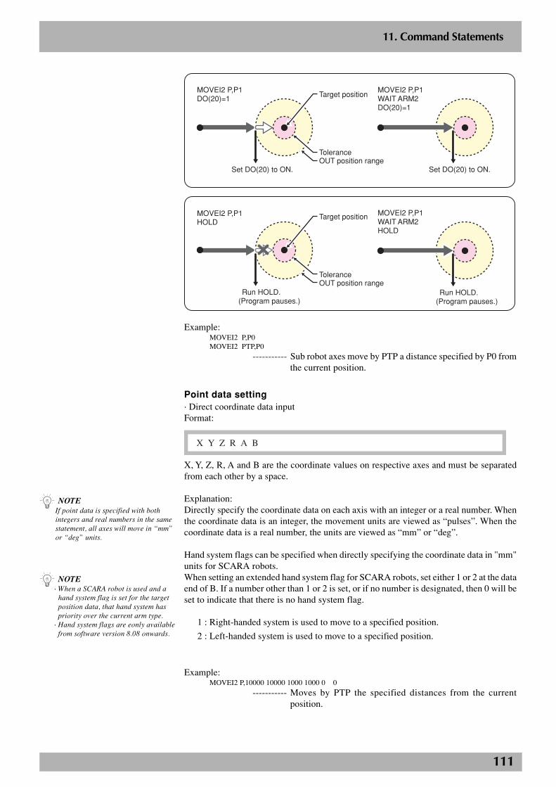
111
2
11. Command Statements
P1
Set DO(20) to ON.
MOVEI2 P,P1WAIT ARM2DO(20)=1
Set DO(20) to ON.
MOVEI2 P,P1DO(20)=1
Tolerance
Target position
OUT position range
Run HOLD.(Program pauses.)
MOVEI2 P,P1WAIT ARM2HOLD
MOVEI2 P,P1HOLD
ToleranceOUT position range
Target position
Run HOLD.(Program pauses.)
Example:MOVEI2 P,P0MOVEI2 PTP,P0
----------- Sub robot axes move by PTP a distance specified by P0 fromthe current position.
Point data setting· Direct coordinate data inputFormat:
X Y Z R A B
X, Y, Z, R, A and B are the coordinate values on respective axes and must be separatedfrom each other by a space.
Explanation:Directly specify the coordinate data on each axis with an integer or a real number. Whenthe coordinate data is an integer, the movement units are viewed as “pulses”. When thecoordinate data is a real number, the units are viewed as “mm” or “deg”.
Hand system flags can be specified when directly specifying the coordinate data in "mm"units for SCARA robots.When setting an extended hand system flag for SCARA robots, set either 1 or 2 at the dataend of B. If a number other than 1 or 2 is set, or if no number is designated, then 0 will beset to indicate that there is no hand system flag.
1 : Right-handed system is used to move to a specified position.
2 : Left-handed system is used to move to a specified position.
Example:MOVEI2 P,10000 10000 1000 1000 0 0
----------- Moves by PTP the specified distances from the currentposition.
n NOTE· When a SCARA robot is used and a
hand system flag is set for the targetposition data, that hand system haspriority over the current arm type.
· Hand system flags are eonly availablefrom software version 8.08 onwards.
n NOTEIf point data is specified with bothintegers and real numbers in the samestatement, all axes will move in “mm”or “deg” units.
112
2
11. Command Statements
· Point definitionFormat:
<point expression> [, <point expression> …]
Explanation:Specify the point data in <point expression>. Two or more pieces of data can be designatedby separating them with a comma ( , ).
Example:MOVEI2 P,P1
----------- Moves by PTP a distance specified by P1 from the currentposition.
Option type· Speed settingFormat 1:
SPEED = <expression>
S
The value of <expression> must be from 1 to 100. (Unit: %)
Explanation:Specify the program speed in <expression>. Robot operating speed is determined by theproduct of the automatic movement speed and the program speed. This option is enabledonly for the specified MOVEI2 statement.
Example:MOVEI2 P,P10,S=10
----------- Moves by PTP a distance specified by P1 from the currentposition using a program speed of 10%.
Related commands: MOVE2, DRIVE2, DRIVEI2, WAIT ARM2
n NOTEThis option merely specifies themaximum speed and does notguarantee the specified speed.
n NOTEWhen a SCARA robot is used and ahand system flag is set for the pointdata you specify, that hand system haspriority over the current arm type.
113
2
11. Command Statements
ON ERROR GOTO statement
Format:
ON ERROR GOTO <label>
0
Error output information ERR : Error numberERL : Line number of error
Explanation:Even if an error occurs during execution of the robot language, this statement allows theprogram to jump to the error processing routine specified by <label>, so that the programstill continues without being suspended. (Some serious errors are excluded.) If “0” isspecified for <label> in this statement, the program stops when an error is issued and theerror message is displayed.The error processing routine processes the error using the RESUME statement and handlesthe error output information.
Example:ON ERROR GOTO *ER1FOR A = 0 TO 9
P[A+10] = P[A]NEXT A*L99: HALT’ERROR ROUTINE*ER1:IF ERR = &H0604 THEN *NEXT1
----------- Checks whether an error “Point doesn't exist” has occurred.IF ERR = &H0606 THEN *NEXT2
----------- Checks whether an error “Subscript out of range” hasoccurred.
ON ERROR GOTO 0
----------- Displays the error message and stops the program execution.*NEXT1:
RESUME NEXT
----------- Jumps to the next command line after the line where the erroroccurred, and continues executing the program.
*NEXT2:RESUME *L99
----------- Jumps to the label “*L99” and continues executing theprogram.
Related commands: RESUME
n NOTE· If a serious error such as “Over
load” occurs, the program executionstops.
· The last “ON ERROR GOTO<label>” statement that was used isvalid.
· If an error occurs while an errorprocessing routine is being executed,the program will stop.
· “ON ERROR GOTO <label>”statements cannot be executed withinerror processing routines.
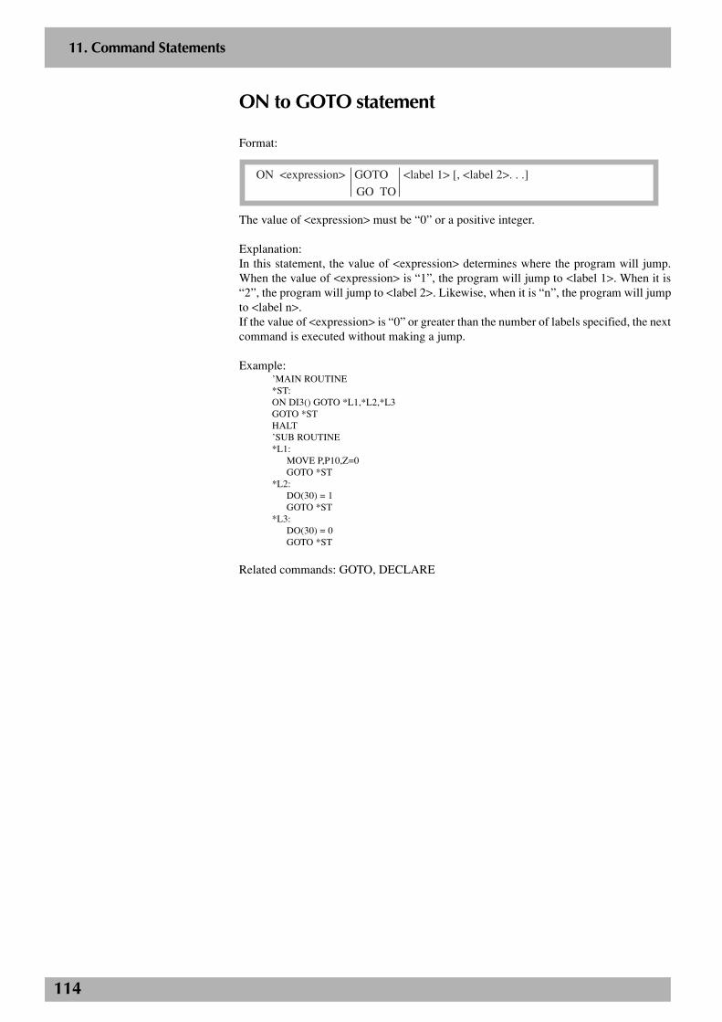
114
2
11. Command Statements
ON to GOTO statement
Format:
ON <expression> GOTO <label 1> [, <label 2>. . .]
GO TO
The value of <expression> must be “0” or a positive integer.
Explanation:In this statement, the value of <expression> determines where the program will jump.When the value of <expression> is “1”, the program will jump to <label 1>. When it is“2”, the program will jump to <label 2>. Likewise, when it is “n”, the program will jumpto <label n>.If the value of <expression> is “0” or greater than the number of labels specified, the nextcommand is executed without making a jump.
Example:’MAIN ROUTINE*ST:ON DI3() GOTO *L1,*L2,*L3GOTO *STHALT’SUB ROUTINE*L1:
MOVE P,P10,Z=0GOTO *ST
*L2:DO(30) = 1GOTO *ST
*L3:DO(30) = 0GOTO *ST
Related commands: GOTO, DECLARE
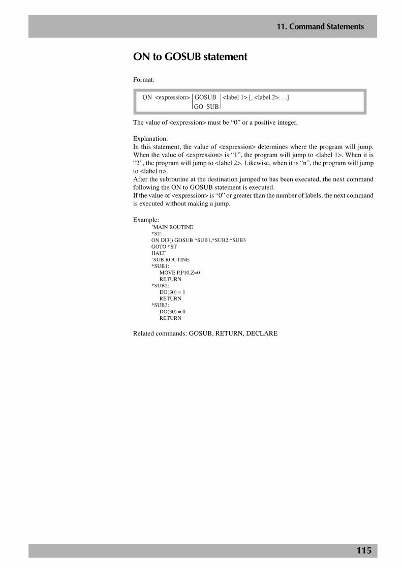
115
2
11. Command Statements
ON to GOSUB statement
Format:
ON <expression> GOSUB <label 1> [, <label 2>. . .]
GO SUB
The value of <expression> must be “0” or a positive integer.
Explanation:In this statement, the value of <expression> determines where the program will jump.When the value of <expression> is “1”, the program will jump to <label 1>. When it is“2”, the program will jump to <label 2>. Likewise, when it is “n”, the program will jumpto <label n>.After the subroutine at the destination jumped to has been executed, the next commandfollowing the ON to GOSUB statement is executed.If the value of <expression> is “0” or greater than the number of labels, the next commandis executed without making a jump.
Example:’MAIN ROUTINE*ST:ON DI3() GOSUB *SUB1,*SUB2,*SUB3GOTO *STHALT’SUB ROUTINE*SUB1:
MOVE P,P10,Z=0RETURN
*SUB2:DO(30) = 1RETURN
*SUB3:DO(30) = 0RETURN
Related commands: GOSUB, RETURN, DECLARE
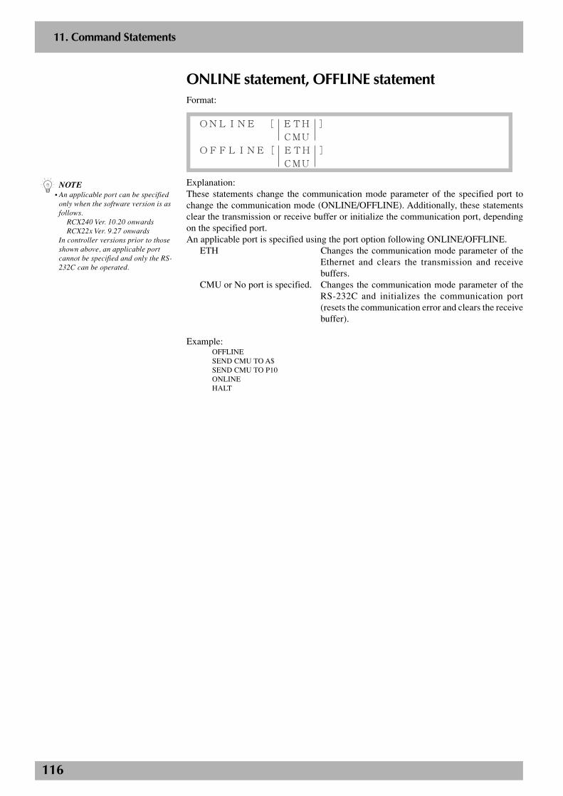
116
2
11. Command Statements
ONLINE statement, OFFLINE statementFormat:
ONLINE [ ETH ]
CMU
OFFLINE[ ETH ]
CMU
Explanation:These statements change the communication mode parameter of the specified port tochange the communication mode (ONLINE/OFFLINE). Additionally, these statementsclear the transmission or receive buffer or initialize the communication port, dependingon the specified port.An applicable port is specified using the port option following ONLINE/OFFLINE.
ETH Changes the communication mode parameter of theEthernet and clears the transmission and receivebuffers.
CMU or No port is specified. Changes the communication mode parameter of theRS-232C and initializes the communication port(resets the communication error and clears the receivebuffer).
Example:OFFLINESEND CMU TO A$SEND CMU TO P10ONLINEHALT
n NOTE• An applicable port can be specified
only when the software version is asfollows.
RCX240 Ver. 10.20 onwardsRCX22x Ver. 9.27 onwards
In controller versions prior to thoseshown above, an applicable portcannot be specified and only the RS-232C can be operated.
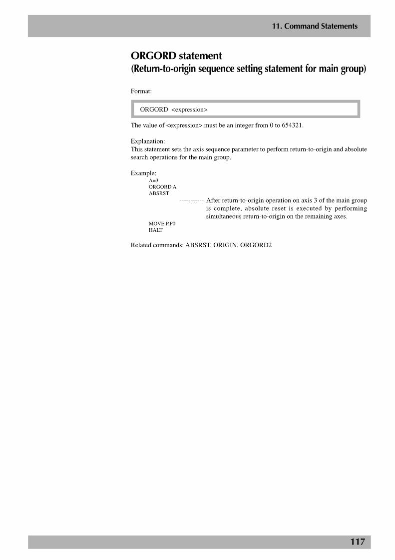
117
2
11. Command Statements
ORGORD statement(Return-to-origin sequence setting statement for main group)
Format:
ORGORD <expression>
The value of <expression> must be an integer from 0 to 654321.
Explanation:This statement sets the axis sequence parameter to perform return-to-origin and absolutesearch operations for the main group.
Example:A=3ORGORD AABSRST
----------- After return-to-origin operation on axis 3 of the main groupis complete, absolute reset is executed by performingsimultaneous return-to-origin on the remaining axes.
MOVE P,P0HALT
Related commands: ABSRST, ORIGIN, ORGORD2
118
2
11. Command Statements
ORGORD2 statement(Return-to-origin sequence setting statement for sub group)
Format:
ORGORD2 <expression>
The value of <expression> must be an integer from 0 to 4321.
Explanation:This statement sets the axis sequence parameter to perform return-to-origin and absolutesearch operations for the sub group.
Example:A=1234ORGORD2 AABSRSTMOVE2 P,P0HALT
Related commands: ABSRST, ORIGIN, ORGORD

119
2
11. Command Statements
ORIGIN statementFormat:
ORIGIN
Explanation:This statement performs return-to-origin on an incremental mode axis or absolute searchon a semi-absolute axis.If the movement is stopped halfway, then origin is incomplete.When two robots are specified, return-to-origin and absolute search are first performedon the main group and then on the sub robot group.
Example:ORIGIN
----------- Performs return-to-origin on an incremental mode axis.(Performs an absolute search on a semi-absolute mode axis.)
Related commands: ABSRST, ORGORD, ORGORD2, MCHREF, MCHREF2
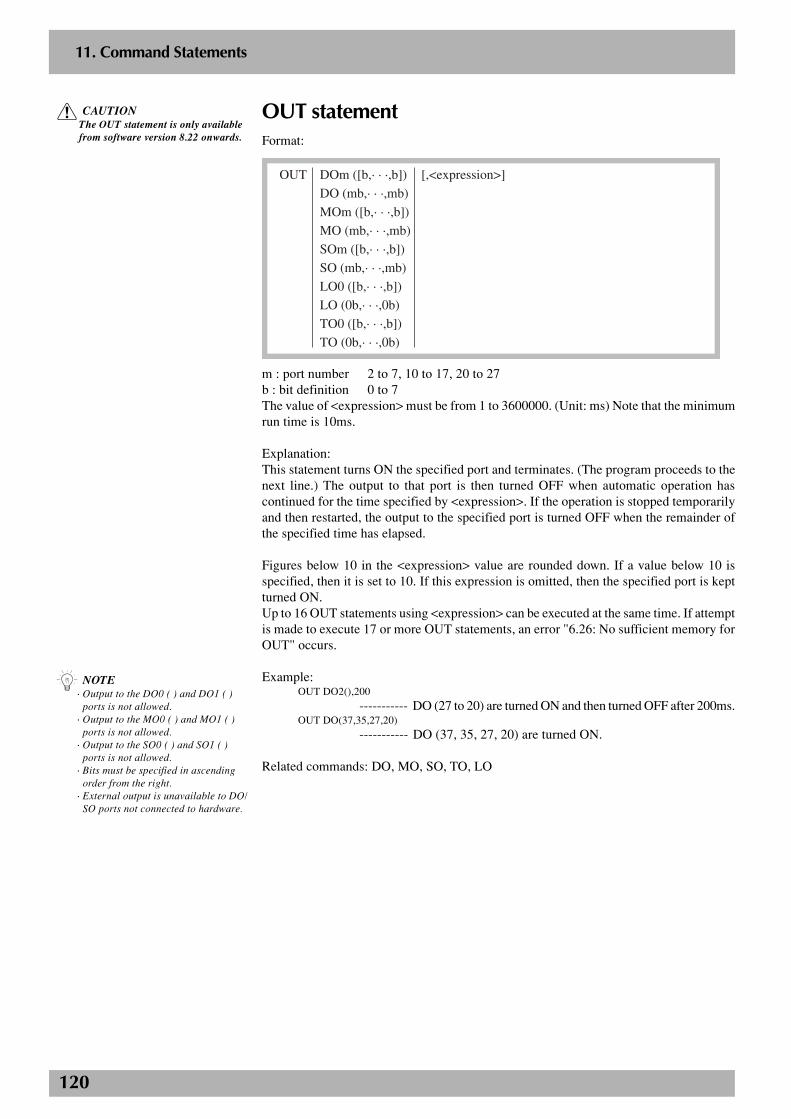
120
2
11. Command Statements
OUT statementFormat:
OUT DOm ([b,· · ·,b]) [,<expression>]
DO (mb,· · ·,mb)
MOm ([b,· · ·,b])
MO (mb,· · ·,mb)
SOm ([b,· · ·,b])
SO (mb,· · ·,mb)
LO0 ([b,· · ·,b])
LO (0b,· · ·,0b)
TO0 ([b,· · ·,b])
TO (0b,· · ·,0b)
m : port number 2 to 7, 10 to 17, 20 to 27b : bit definition 0 to 7The value of <expression> must be from 1 to 3600000. (Unit: ms) Note that the minimumrun time is 10ms.
Explanation:This statement turns ON the specified port and terminates. (The program proceeds to thenext line.) The output to that port is then turned OFF when automatic operation hascontinued for the time specified by <expression>. If the operation is stopped temporarilyand then restarted, the output to the specified port is turned OFF when the remainder ofthe specified time has elapsed.
Figures below 10 in the <expression> value are rounded down. If a value below 10 isspecified, then it is set to 10. If this expression is omitted, then the specified port is keptturned ON.Up to 16 OUT statements using <expression> can be executed at the same time. If attemptis made to execute 17 or more OUT statements, an error "6.26: No sufficient memory forOUT" occurs.
Example:OUT DO2(),200
----------- DO (27 to 20) are turned ON and then turned OFF after 200ms.OUT DO(37,35,27,20)
----------- DO (37, 35, 27, 20) are turned ON.
Related commands: DO, MO, SO, TO, LO
c CAUTIONThe OUT statement is only availablefrom software version 8.22 onwards.
n NOTE· Output to the DO0 ( ) and DO1 ( )
ports is not allowed.· Output to the MO0 ( ) and MO1 ( )
ports is not allowed.· Output to the SO0 ( ) and SO1 ( )
ports is not allowed.· Bits must be specified in ascending
order from the right.· External output is unavailable to DO/
SO ports not connected to hardware.
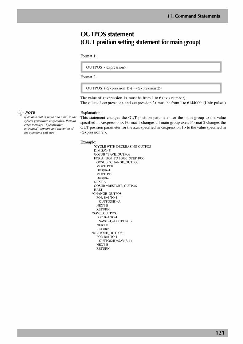
121
2
11. Command Statements
OUTPOS statement(OUT position setting statement for main group)
Format 1:
OUTPOS <expression>
Format 2:
OUTPOS (<expression 1>) = <expression 2>
The value of <expression 1> must be from 1 to 6 (axis number).The value of <expression> and <expression 2> must be from 1 to 6144000. (Unit: pulses)
Explanation:This statement changes the OUT position parameter for the main group to the valuespecified in <expression>. Format 1 changes all main group axes. Format 2 changes theOUT position parameter for the axis specified in <expression 1> to the value specified in<expression 2>.
Example:’CYCLE WITH DECREASING OUTPOSDIM SAV(3)GOSUB *SAVE_OUTPOSFOR A=1000 TO 10000 STEP 1000
GOSUB *CHANGE_OUTPOSMOVE P,P0DO3(0)=1MOVE P,P1DO3(0)=0
NEXT AGOSUB *RESTORE_OUTPOSHALT
*CHANGE_OUTPOS:FOR B=1 TO 4
OUTPOS(B)=ANEXT BRETURN
*SAVE_OUTPOS:FOR B=1 TO 4
SAV(B-1)=OUTPOS(B)NEXT BRETURN
*RESTORE_OUTPOS:FOR B=1 TO 4
OUTPOS(B)=SAV(B-1)NEXT BRETURN
n NOTEIf an axis that is set to “no axis” in thesystem generation is specified, then anerror message “Specificationmismatch” appears and execution ofthe command will stop.
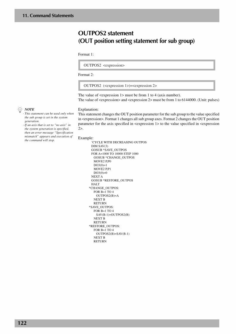
122
2
11. Command Statements
OUTPOS2 statement(OUT position setting statement for sub group)
Format 1:
OUTPOS2 <expression>
Format 2:
OUTPOS2 (<expression 1>)=<expression 2>
The value of <expression 1> must be from 1 to 4 (axis number).The value of <expression> and <expression 2> must be from 1 to 6144000. (Unit: pulses)
Explanation:This statement changes the OUT position parameter for the sub group to the value specifiedin <expression>. Format 1 changes all sub group axes. Format 2 changes the OUT positionparameter for the axis specified in <expression 1> to the value specified in <expression2>.
Example:’CYCLE WITH DECREASING OUTPOSDIM SAV(3)GOSUB *SAVE_OUTPOSFOR A=1000 TO 10000 STEP 1000
GOSUB *CHANGE_OUTPOSMOVE2 P,P0DO3(0)=1MOVE2 P,P1DO3(0)=0
NEXT AGOSUB *RESTORE_OUTPOSHALT
*CHANGE_OUTPOS:FOR B=1 TO 4
OUTPOS2(B)=ANEXT BRETURN
*SAVE_OUTPOS:FOR B=1 TO 4
SAV(B-1)=OUTPOS2(B)NEXT BRETURN
*RESTORE_OUTPOS:FOR B=1 TO 4
OUTPOS2(B)=SAV(B-1)NEXT BRETURN
n NOTE· This statement can be used only when
the sub group is set in the systemgeneration.
· If an axis that is set to “no axis” inthe system generation is specified,then an error message “Specificationmismatch” appears and execution ofthe command will stop.
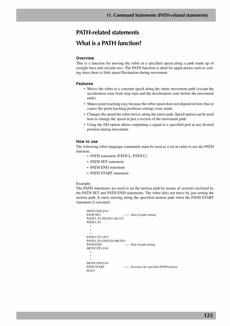
123
2
11. Command Statements (PATH-related statements)
PATH-related statements
What is a PATH function?
OverviewThis is a function for moving the robot at a specified speed along a path made up ofstraight lines and circular arcs. The PATH function is ideal for applications such as seal-ing since there is little speed fluctuation during movement.
Features• Moves the robot at a constant speed along the entire movement path (except the
acceleration zone from stop state and the deceleration zone before the movementends).
• Makes point teaching easy because the robot speed does not depend on how fine orcoarse the point teaching positions settings were made.
• Changes the speed the robot moves along the entire path. Speed option can be usedhere to change the speed at just a section of the movement path.
• Using the DO option allows outputting a signal to a specified port at any desiredposition during movement.
How to useThe following robot language commands must be used as a set in order to use the PATHfunction.
• PATH statement (PATH L, PATH C)
• PATH SET statement
• PATH END statement
• PATH START statement
Example:The PATH statements are used to set the motion path by means of sections enclosed bythe PATH SET and PATH END statements. The robot does not move by just setting themotion path. It starts moving along the specified motion path when the PATH STARTstatement is executed.
MOVE P,P0,Z=0PATH SET ------ Start of path settingPATH L,P1,DO(20)[email protected] L,P2
•••
PATH C,P12,P13PATH L,P14,DO(20)[email protected] END ------ End of path settingMOVE P,P1,Z=0
•••
MOVE P,P0,Z=0PATH START ------ Executes the specified PATH motionHALT
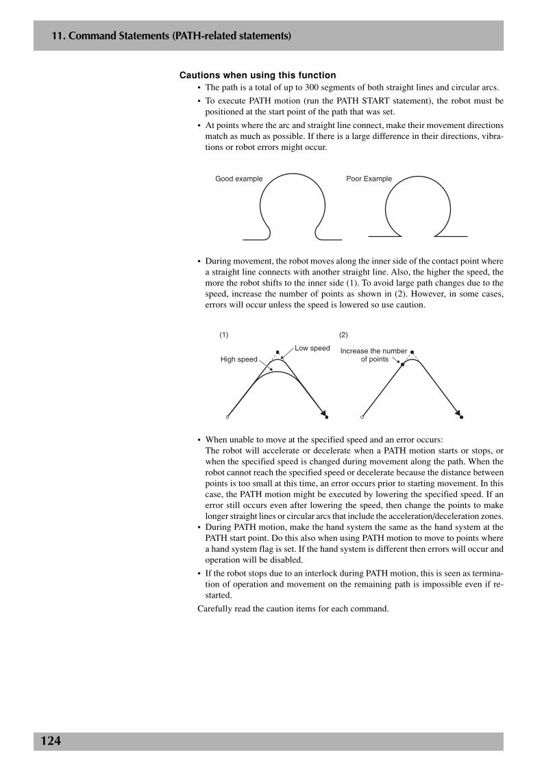
124
2
11. Command Statements (PATH-related statements)
Cautions when using this function• The path is a total of up to 300 segments of both straight lines and circular arcs.
• To execute PATH motion (run the PATH START statement), the robot must bepositioned at the start point of the path that was set.
• At points where the arc and straight line connect, make their movement directionsmatch as much as possible. If there is a large difference in their directions, vibra-tions or robot errors might occur.
Good example Poor Example
• During movement, the robot moves along the inner side of the contact point wherea straight line connects with another straight line. Also, the higher the speed, themore the robot shifts to the inner side (1). To avoid large path changes due to thespeed, increase the number of points as shown in (2). However, in some cases,errors will occur unless the speed is lowered so use caution.
(1) (2)
Increase the number of pointsHigh speed
Low speed
• When unable to move at the specified speed and an error occurs:The robot will accelerate or decelerate when a PATH motion starts or stops, orwhen the specified speed is changed during movement along the path. When therobot cannot reach the specified speed or decelerate because the distance betweenpoints is too small at this time, an error occurs prior to starting movement. In thiscase, the PATH motion might be executed by lowering the specified speed. If anerror still occurs even after lowering the speed, then change the points to makelonger straight lines or circular arcs that include the acceleration/deceleration zones.
• During PATH motion, make the hand system the same as the hand system at thePATH start point. Do this also when using PATH motion to move to points wherea hand system flag is set. If the hand system is different then errors will occur andoperation will be disabled.
• If the robot stops due to an interlock during PATH motion, this is seen as termina-tion of operation and movement on the remaining path is impossible even if re-started.
Carefully read the caution items for each command.
125
2
11. Command Statements (PATH-related statements)
PATH statement (PATH-related statements)
Format:
PATH L , <point definition> [, option [, option...] ]
C
Explanation:This command statement sets the PATH motion path for the main robot axis.Executing this command without first running the PATH SET command will cause anerror.
PATH motion type : Linear interpolation, circular interpolationPoint data setting : Direct coordinate data input, point definitionOptions : Speed setting, coordinate plane setting (circular interpola-
tion only), port output setting
PATH motion type• Linear interpolation movement --------Sets linear interpolation movement with
"PATH L...".
• Circular interpolation movement ------ Sets circular interpolation movement with"PATH C...".
PATH motion is only valid for the X, Y and Z coordinate values of the specifiedpoints. The other coordinates use the coordinate value of the start point on thePATH motion path.
Movement path can be connected by repeated use of PATH commands ("PATH L","PATH C") to allow movement without stopping.
Point data setting· Direct coordinate data inputFormat:
X Y Z R A B
X, Y, Z, R, A, and B are coordinate values on respective axes and must be separated fromeach other by a space.
Explanation:Directly specify the coordinate data. When the coordinate data is an integer, it is viewedas "pulses" units. When the coordinate data is a real number, it is viewed as "mm" units.If both integers and real numbers are used, then all coordinates are handled in "mm"units.With this format, only one point can be specified as the movement destination coordi-nates. The only type of movement specified by this point data setting is linear interpola-tion.
Hand system flags can be specified when directly specifying the coordinate data in "mm"units for SCARA robots.When setting an extended hand system flag for SCARA robots, set either 1 or 2 at the dataend of B. If a number other than 1 or 2 is set, or if no number is designated, then 0 will beset to indicate that there is no hand system flag.
1 : Right-handed system is used to move to a specified position.
2 : Left-handed system is used to move to a specified position.
n NOTEWhen a SCARA robot is used and ahand system flag is set for the targetposition data, that hand system haspriority over the current arm type.
c CAUTIONSet the hand system for PATH motionto the same hand system as that at thestart point of the PATH motion. Whenmoving by specifying a hand systemflag, also set the hand system to bethe same as that at the start point forthe path. If the hand system isdifferent, then an error occurs andoperation is impossible.
n NOTEPATH statement is only available fromsoftware version 8.38 onwards.
126
2
11. Command Statements (PATH-related statements)
Example:PATH L,10000 10000 1000 1000 0 0
----------- Sets for movement by linear interpolation to the specifiedposition.
PATH L,150.00 250.00 10.00 30.00 0.00 0.00 1
----------- Sets for movement by linear interpolation to the position speci-fied in the right-handed system.
· Point definitionFormat:
<point expression> [, <point expression> …]
Explanation:In <point expression>, specify the point to move to. Two or more points can be specifiedby separating them with a comma (,).When the PATH motion type is circular interpolation, two points must be specified foreach single circular arc.
Example:PATH L,P1,P2,P3
----------- Sets for movement by linear interpolation in sequence to po-sitions specified by P1, P2 and P3.
PATH C P5,P6,P7,P8
----------- Sets for movement by circular interpolation including thecurrent position, P5, P6 and P6, P7 and P8.
Option types· Speed settingFormat 1:
SPEED = <expression>
S
The value in <expression> must be from 1 to 100. (Unit: %)
Explanation:Specify the program speed in <expression> (unit: %).Actual speed is as follows.
Robot maximum speed (mm/sec.) × automatic movement speed (%) × program speed (%)This option is enabled only for the specified PATH statement.
Example:PATH L, P5, S=40
----------- Moves to the position specified by P5 using a program speedof 40%.
n NOTEWhen a SCARA robot is used and ahand system flag is set for the pointdata you specify, that hand system haspriority over the current arm type.
c CAUTIONSet the hand system for PATH motionto the same hand system as that at thestart point of the PATH motion. Whenmoving by specifying a hand systemflag, also set the hand system to bethe same as that at the start point ofthe PATH motion. If the hand systemis different, then an error occurs andoperation is impossible.
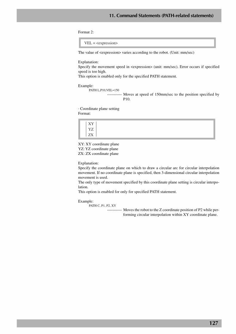
127
2
11. Command Statements (PATH-related statements)
Format 2:
VEL = <expression>
The value of <expression> varies according to the robot. (Unit: mm/sec)
Explanation:Specify the movement speed in <expression> (unit: mm/sec). Error occurs if specifiedspeed is too high.This option is enabled only for the specified PATH statement.
Example:PATH L,P10,VEL=150
----------- Moves at speed of 150mm/sec to the position specified byP10.
· Coordinate plane settingFormat:
XY
YZ
ZX
XY: XY coordinate planeYZ: YZ coordinate planeZX: ZX coordinate plane
Explanation:Specify the coordinate plane on which to draw a circular arc for circular interpolationmovement. If no coordinate plane is specified, then 3-dimensional circular interpolationmovement is used.The only type of movement specified by this coordinate plane setting is circular interpo-lation.This option is enabled for only for specified PATH statement.
Example:PATH C, P1, P2, XY
----------- Moves the robot to the Z coordinate position of P2 while per-forming circular interpolation within XY coordinate plane.
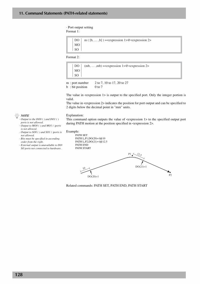
128
2
11. Command Statements (PATH-related statements)
· Port output settingFormat 1:
DO m ( [b, … ,b] ) =<expression 1>@<expression 2>
MO
SO
Format 2:
DO (mb, … ,mb) =<expression 1>@<expression 2>
MO
SO
m : port number 2 to 7, 10 to 17, 20 to 27b : bit position 0 to 7
The value in <expression 1> is output to the specified port. Only the integer portion isvalid.The value in <expression 2> indicates the position for port output and can be specified to2 digits below the decimal point in "mm" units.
Explanation:This command option outputs the value of <expression 1> to the specified output portduring PATH motion at the position specified in <expression 2>.
Example:PATH SETPATH L,P1,DO(20)=1@10PATH L,P2,DO(21)[email protected] ENDPATH START
P1
P2
10
12.5
DO(20)=1
DO(21)=1
Related commands: PATH SET, PATH END, PATH START
n NOTE· Output to the DO0 ( ) and DO1 ( )
ports is not allowed.· Output to MO0 ( ) and MO1 ( )ports
is not allowed.· Output to SO0 ( ) and SO1 ( )ports is
not allowed.· Bits must be specified in ascending
order from the right.· External output is unavailable to DO/
SO ports not connected to hardware.
129
2
11. Command Statements (PATH-related statements)
PATH END statement (PATH-related statements)
Format:
PATH END
Explanation:This is used to terminate the path setting for PATH motion.The PATH END command must always be used as a pair along with the PATH SETcommand. The final point of the PATH command ("PATH L" or "PATH C") that wasexecuted last between the PATH SET and PATH END commands is the end point of thePATH motion.An error will occur if the PATH END command is executed without first running PATHSET.
Example:See the "What is a PATH function?" description.
Related commands: PATH, PATH SET, PATH START
n NOTEPATH END statement is only availablefrom software version 8.38 onwards.
130
2
11. Command Statements (PATH-related statements)
PATH SET statement (PATH-related statements)
Format:
PATH SET [<Point definition>]
Explanation:Starts the path setting for PATH motion.Sets the position specified in <point definition> as the PATH motion start point. (Thisonly sets the PATH motion start point and does not mean the robot actually operates.) If<point definition> is omitted, then the current robot position is set as the start point.However, during robot movement, the target position for that movement becomes thestart point. (Example: OUT position range with MOVE command is wide prior to PATHSET command, so robot still moves during execution of the PATH SET command.)The PATH SET command must always be used as a pair along with the PATH ENDcommand.When the PATH SET command is executed, the previously set PATH motion data is de-leted.
Point data setting : Direct coordinate data input, point definition
Example:See the "What is a PATH function?" description.
Point data setting· Direct coordinate data inputFormat:
X Y Z R A B
X, Y, Z, R, A, and B are the coordinate values on respective axes and must be separatedfrom each other by a space.
Explanation:Directly specify the start position coordinates for PATH motion path. When the coordi-nate data is an integer, it is viewed as "pulses" units. When the coordinate data is a realnumber, it is viewed as "mm" units (valid to 2 digits below the decimal point.) If bothintegers and real numbers are used, then all coordinates are handled in "mm" units.
Hand system flags can be specified when directly specifying the coordinate data in "mm"units for SCARA robots.When setting an extended hand system flag for SCARA robots, set either 1 or 2 at the dataend of B. If a number other than 1 or 2 is set, or if no number is designated, then 0 will beset to indicate that there is no hand system flag.
1 : Hand system at PATH motion start point is set to the right-handed system.
2 : Hand system at PATH motion start point is set to the left-handed system.
n NOTEPATH SET statement is only availablefrom software version 8.38 onwards.
n NOTEWhen a SCARA robot is used and ahand system flag is set for the startpoint data of the PATH motion path,that hand system has priority over thecurrent arm type.
c CAUTIONSet the hand system for PATH motionto the same hand system as that at thestart point of the PATH motion. If thehand system is different, then anerror occurs and operation isimpossible.
131
2
11. Command Statements (PATH-related statements)
Example:PATH SET 120 250.00 55.2 20.33 0 0
----------- PATH motion start point is set to (120.00 250.00 55.20 20.330.00 0.00) in "mm" units.
PATH SET -51200 80521 7045 204410 0 0
----------- PATH motion start point is set in "pulses" units.
· Point definitionFormat:
<point expression>
Explanation:Specify the PATH motion start point in <point expression>.
PATH SET P10----------- Sets the PATH motion start point to P10.
PATH SET WHERE
----------- Sets the PATH motion start point the current robot position.
Related commands: PATH, PATH END, PATH START
n NOTEWhen a SCARA robot is used and ahand system flag is set for the pointdata you specify, that hand system haspriority over the current arm type.
c CAUTIONSet the hand system for PATH motionto the same hand system as that at thestart point of the PATH motion. If thehand system is different, then anerror occurs and operation isimpossible.
132
2
11. Command Statements (PATH-related statements)
PATH START statement (PATH-related statements)
Format:
PATH START
Explanation:Starts the PATH motion. PATH motion settings must be made beforehand with the PATHSET command, PATH commands ("PATH L", "PATH C") and PATH END commandbefore executing the PATH START command. Also, before starting PATH motion, therobot must also be positioned beforehand at the PATH motion start point specified by thePATH SET command.The robot PATH motion speed is the product of the automatic movement speed (%) whenthe PATH START command is executed and the program speed (%) specified by theSPEED command or speed option (SPEED or S) for the PATH command. Robot speeddoes not rely on automatic movement speed, if the speed was specified with the speedoption (VEL)for the PATH command.After PATH motion starts, this command terminates when the robot reaches the PATHmotion end point or when the robot stops due to an interlock.This command can only be executed in Task 1 (main task).
Example:See the "What is a PATH function?" description.
Related commands: PATH, PATH SET, PATH END
n NOTEPATH START statement is onlyavailable from software version 8.38onwards.
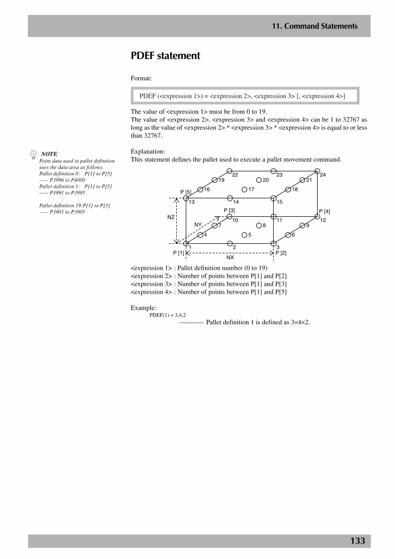
133
2
11. Command Statements
PDEF statement
Format:
PDEF (<expression 1>) = <expression 2>, <expression 3> [, <expression 4>]
The value of <expression 1> must be from 0 to 19.The value of <expression 2>, <expression 3> and <expression 4> can be 1 to 32767 aslong as the value of <expression 2> * <expression 3> * <expression 4> is equal to or lessthan 32767.
Explanation:This statement defines the pallet used to execute a pallet movement command.
P [5]
P [3] P [4]
P [2]P [1]
NZ
NX
NY
4
710
1
16
1922
13
2
5
811
3
6
912
14
17
2023
15
18
2124
<expression 1> : Pallet definition number (0 to 19)<expression 2> : Number of points between P[1] and P[2]<expression 3> : Number of points between P[1] and P[3]<expression 4> : Number of points between P[1] and P[5]
Example:PDEF(1) = 3,4,2
----------- Pallet definition 1 is defined as 3×4×2.
n NOTEPoint data used in pallet definitionuses the data area as follows.Pallet definition 0: P[1] to P[5]----- P3996 to P4000Pallet definition 1: P[1] to P[5]----- P3991 to P3995 :Pallet definition 19:P[1] to P[5]----- P3901 to P3905

134
2
11. Command Statements
PMOVE statement (Pallet movement command)
Format:
PMOVE (pallet definition number, pallet position number) [,option [,option] …]
Explanation:This statement executes a pallet movement command for all main robot axes. This statementwill not move the sub robot axes and auxiliary axes.
Movement type : PTPPallet definition number : Numerical expressionPallet position number : Numerical expressionOptions : Speed setting, arch motion setting, STOPON
condition setting
Movement type· PTP (point to point) movementPTP movement begins after positioning on all movable axes is complete (within thetolerance range), and the command terminates when all movable axes enter the OUTposition range. All movable axes will reach the target positions simultaneously, but theirpaths are not guaranteed.
Cautions for next command following PMOVE commandIf the next command following the PMOVE command is an executable command such asa signal output command, that next command will start when the movement axis entersthe OUT position range. In other words, that next command starts before the axis arriveswithin the target position tolerance range.Examples:
Signal output (DO, etc.)
DELAY
HALT
HOLD
WAIT
Signal is output when axis enters within OUT position range.
DELAY command is executed and time standby starts, when axis enters within OUT position range.
Program stops and is also reset when axis enters within OUT position range. So axis movement stops.
Program temporarily stops when axis enters within OUT position range. So axis movement stops.
WAIT command is executed when axis enters within OUT position range.
To execute the next command after waiting for the axes to arrive within the target positiontolerance range, use the WAIT ARM statement.
n NOTE· The pallet definition number must be
designated to execute a PMOVEstatement.
· The XYZ axes move to the positionsdetermined by the calculated values.However, the R-axis moves to theposition specified by pallet point dataP[1].
· In each pallet definition, palletposition numbers are designated asfollows:
P [1]
NZ
P [5]NX*(NY-1)+1
NX+1
21
NX
NX
P [2]
NX*2
NX*NY
P [4]
NXNX*NYNY*(NZ-1)+NX(NZ-1)+NXNX*NY*(NZ-1)+NX
NX*NY*NZ
NY
NXNX*NYNY*(NZ-1)+1(NZ-1)+1NX*NY*(NZ-1)+1
P [3]P [3]P [3]
...
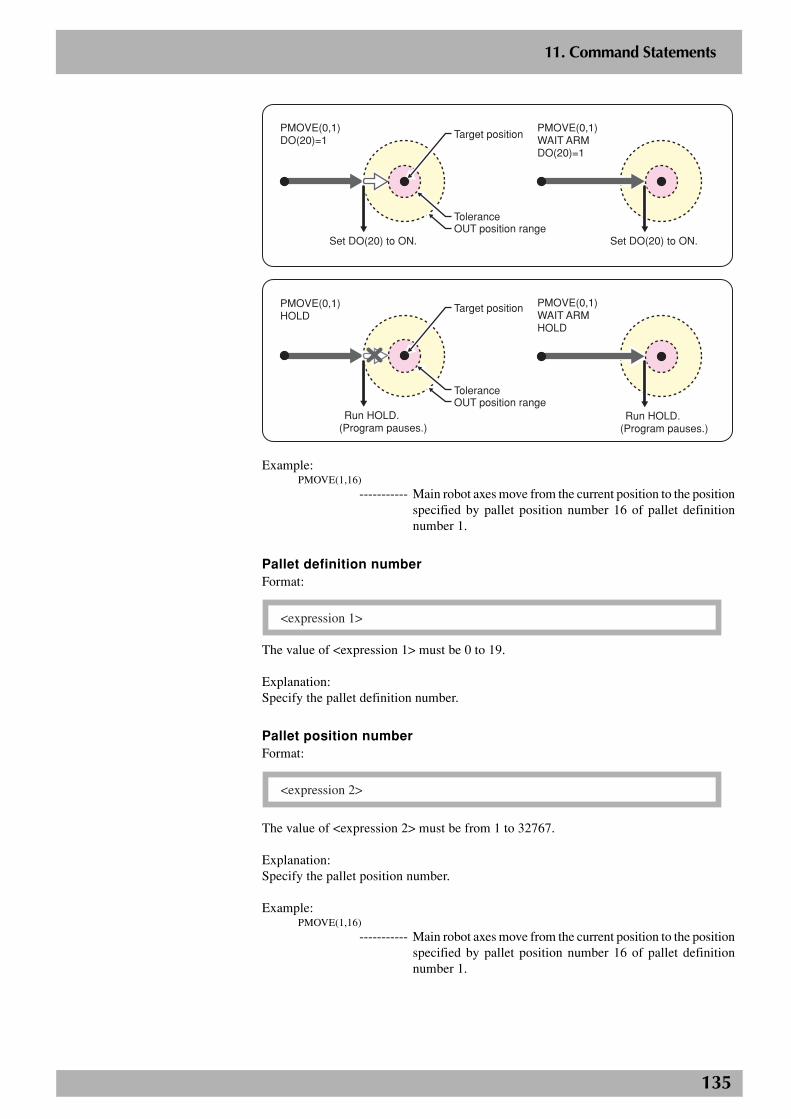
135
2
11. Command Statements
P1
Set DO(20) to ON.
PMOVE(0,1)WAIT ARMDO(20)=1
Set DO(20) to ON.
PMOVE(0,1)DO(20)=1
Tolerance
Target position
OUT position range
Run HOLD.(Program pauses.)
PMOVE(0,1)WAIT ARMHOLD
PMOVE(0,1)HOLD
ToleranceOUT position range
Target position
Run HOLD.(Program pauses.)
Example:PMOVE(1,16)
----------- Main robot axes move from the current position to the positionspecified by pallet position number 16 of pallet definitionnumber 1.
Pallet definition numberFormat:
<expression 1>
The value of <expression 1> must be 0 to 19.
Explanation:Specify the pallet definition number.
Pallet position numberFormat:
<expression 2>
The value of <expression 2> must be from 1 to 32767.
Explanation:Specify the pallet position number.
Example:PMOVE(1,16)
----------- Main robot axes move from the current position to the positionspecified by pallet position number 16 of pallet definitionnumber 1.
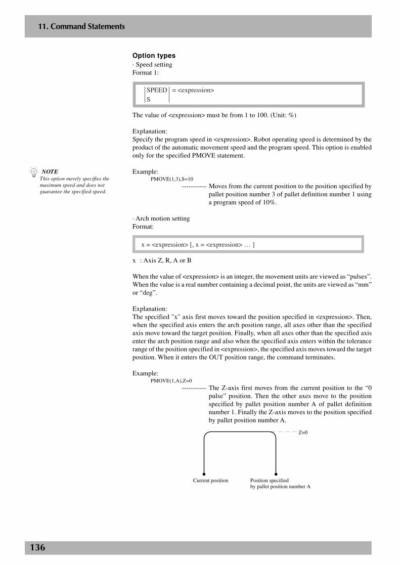
136
2
11. Command Statements
Option types· Speed settingFormat 1:
SPEED = <expression>
S
The value of <expression> must be from 1 to 100. (Unit: %)
Explanation:Specify the program speed in <expression>. Robot operating speed is determined by theproduct of the automatic movement speed and the program speed. This option is enabledonly for the specified PMOVE statement.
Example:PMOVE(1,3),S=10
----------- Moves from the current position to the position specified bypallet position number 3 of pallet definition number 1 usinga program speed of 10%.
· Arch motion settingFormat:
x = <expression> [, x = <expression> … ]
x : Axis Z, R, A or B
When the value of <expression> is an integer, the movement units are viewed as “pulses”.When the value is a real number containing a decimal point, the units are viewed as “mm”or “deg”.
Explanation:The specified "x" axis first moves toward the position specified in <expression>. Then,when the specified axis enters the arch position range, all axes other than the specifiedaxis move toward the target position. Finally, when all axes other than the specified axisenter the arch position range and also when the specified axis enters within the tolerancerange of the position specified in <expression>, the specified axis moves toward the targetposition. When it enters the OUT position range, the command terminates.
Example:PMOVE(1,A),Z=0
----------- The Z-axis first moves from the current position to the “0pulse” position. Then the other axes move to the positionspecified by pallet position number A of pallet definitionnumber 1. Finally the Z-axis moves to the position specifiedby pallet position number A.
Current position
Z=0
Position specified by pallet position number A
n NOTEThis option merely specifies themaximum speed and does notguarantee the specified speed.
137
2
11. Command Statements
· STOPON condition settingFormat:
STOPON <conditional expression>
Explanation:This command option stops the robot movement when the conditional expression is met(becomes true). The robot will move a slight distance while slowing down before comingto a stop after the condition is met (conditional expression becomes true).If the conditional expression is already satisfied (true) before the robot begins to move,the command will terminate without moving the robot.This option is enabled only during program execution.
Example:PMOVE(A,16),STOPON DI(20)=1
----------- Moves from the current position to the position specified bypallet position number 16 of pallet definition number A, andslows down and stops when the condition “DI (20) = 1” ismet.
n NOTEOn controllers using the followingsoftware versions, when theconditional expression used todesignate the STOPON condition is anumeric expression, the "TRUEcondition" parameter of "Otherparameters" (SYSTEM > PARAM >OTHERS mode) can be set to changethe conditions for determining "true"and "false" (-1 is "true" and 0 is"false", or a value other than 0 is"true" and 0 is "false"). Refer to thecontroller user's manual for detailedinformation.
RCX14x Ver. 8.63 onwards,RCX22x Ver. 9.08 onwards
On earlier version controllers, -1 is"true" and a value other than -1 is"false".
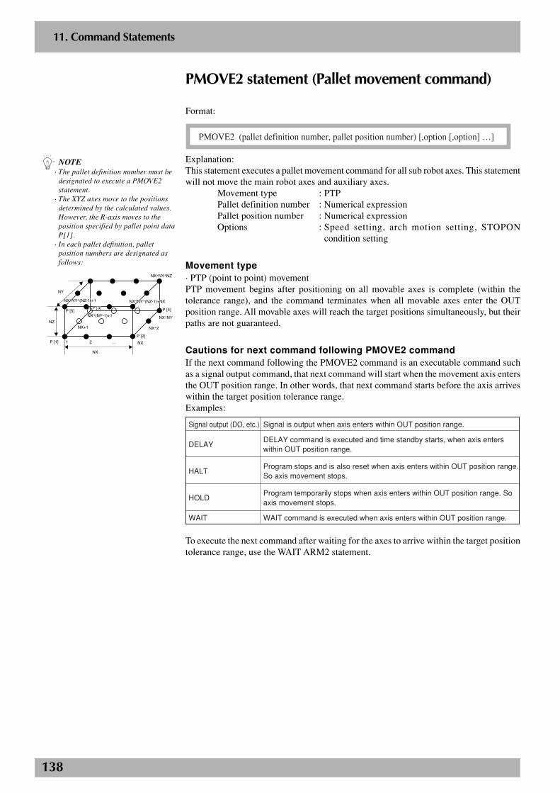
138
2
11. Command Statements
PMOVE2 statement (Pallet movement command)
Format:
PMOVE2 (pallet definition number, pallet position number) [,option [,option] …]
Explanation:This statement executes a pallet movement command for all sub robot axes. This statementwill not move the main robot axes and auxiliary axes.
Movement type : PTPPallet definition number : Numerical expressionPallet position number : Numerical expressionOptions : Speed setting, arch motion setting, STOPON
condition setting
Movement type· PTP (point to point) movementPTP movement begins after positioning on all movable axes is complete (within thetolerance range), and the command terminates when all movable axes enter the OUTposition range. All movable axes will reach the target positions simultaneously, but theirpaths are not guaranteed.
Cautions for next command following PMOVE2 commandIf the next command following the PMOVE2 command is an executable command suchas a signal output command, that next command will start when the movement axis entersthe OUT position range. In other words, that next command starts before the axis arriveswithin the target position tolerance range.Examples:
Signal output (DO, etc.)
DELAY
HALT
HOLD
WAIT
Signal is output when axis enters within OUT position range.
DELAY command is executed and time standby starts, when axis enters within OUT position range.
Program stops and is also reset when axis enters within OUT position range. So axis movement stops.
Program temporarily stops when axis enters within OUT position range. So axis movement stops.
WAIT command is executed when axis enters within OUT position range.
To execute the next command after waiting for the axes to arrive within the target positiontolerance range, use the WAIT ARM2 statement.
n NOTE· The pallet definition number must be
designated to execute a PMOVE2statement.
· The XYZ axes move to the positionsdetermined by the calculated values.However, the R-axis moves to theposition specified by pallet point dataP[1].
· In each pallet definition, palletposition numbers are designated asfollows:
P [1]
NZ
P [5]NX*(NY-1)+1
NX+1
21
NX
NX
P [2]
NX*2
NX*NY
P [4]
NXNX*NYNY*(NZ-1)+NX(NZ-1)+NXNX*NY*(NZ-1)+NX
NX*NY*NZ
NY
NXNX*NYNY*(NZ-1)+1(NZ-1)+1NX*NY*(NZ-1)+1
P [3]P [3]P [3]
...

139
2
11. Command Statements
P1
Set DO(20) to ON.
PMOVE2(0,1)WAIT ARM2DO(20)=1
Set DO(20) to ON.
PMOVE2(0,1)DO(20)=1
Tolerance
Target position
OUT position range
Run HOLD.(Program pauses.)
PMOVE2(0,1)WAIT ARM2HOLD
PMOVE2(0,1)HOLD
ToleranceOUT position range
Target position
Run HOLD.(Program pauses.)
Example:PMOVE2(1,16)
----------- Sub robot axes move from the current position to the positionspecified by pallet position number 16 of pallet definitionnumber 1.
Pallet definition numberFormat:
<expression 1>
The value of <expression 1> must be 0 to 19.
Explanation:Specify the pallet definition number.
Pallet position numberFormat:
<expression 2>
The value of <expression 2> must be from 1 to 32767.
Explanation:Specify the pallet position number.
Example:PMOVE2(1,16)
----------- Sub robot axes move from the current position to the positionspecified by pallet position number 16 of pallet definitionnumber 1.

140
2
11. Command Statements
Option types· Speed settingFormat 1:
SPEED = <expression>
S
The value of <expression> must be from 1 to 100. (Unit: %)
Explanation:Specify the program speed in <expression>. Robot operating speed is determined by theproduct of the automatic movement speed and the program speed. This option is enabledonly for the specified PMOVE2 statement.
Example:PMOVE2(1,3),S=10
----------- Moves from the current position to the position specified bypallet position number 3 of pallet definition number 1 usinga program speed of 10%.
· Arch motion settingFormat:
x = <expression> [, x = <expression> … ]
x: Axis Z or R
When the value of <expression> is an integer, the unit of movement is viewed as “pulses”.When the value is a real number containing a decimal point, the unit is viewed as “mm”or “deg”.
Explanation:The specified "x" axis first moves toward the position specified in <expression>. Then,when the specified axis enters the arch position range, all axes other than the specifiedaxis move toward the target position. Finally, when all axes other than the specified axisenter the arch position range and also when the specified axis enters within the tolerancerange of the position specified in <expression>, the specified axis moves toward the targetposition. When it enters the OUT position range, the command terminates.
Example:PMOVE2(1,A),Z=0
----------- The Z-axis first moves from the current position to the “0pulse” position. Then the other axes move to the positionspecified by pallet position number A of pallet definitionnumber 1. Finally the Z-axis moves to the position specifiedby pallet position number A.
Current position
Z=0
Position specified by pallet position number A
n NOTEThis option merely specifies themaximum speed and does notguarantee the specified speed.
141
2
11. Command Statements
· STOPON condition settingFormat:
STOPON <conditional expression>
Explanation:This command option stops the robot movement when the conditional expression is met(becomes true). The robot will move a slight distance while slowing down before comingto a stop after the condition is met (conditional expression becomes true).If the conditional expression is already satisfied (true) before the robot begins to move,the command will terminate without moving the robot.This option is enabled only during program execution.
Example:PMOVE2(A,16),STOPON DI(20)=1
-------- --- Moves from the current position to the position specified bypallet position number 16 of pallet definition number A, andslows down and stops when the condition “DI (20) = 1” ismet.
n NOTEOn controllers using the followingsoftware versions, when theconditional expression used todesignate the STOPON condition is anumeric expression, the "TRUEcondition" parameter of "Otherparameters" (SYSTEM > PARAM >OTHERS mode) can be set to changethe conditions for determining "true"and "false" (-1 is "true" and 0 is"false", or a value other than 0 is"true" and 0 is "false"). Refer to thecontroller user's manual for detailedinformation.
RCX14x Ver. 8.63 onwards,RCX22x Ver. 9.08 onwards
On earlier version controllers, -1 is"true" and a value other than -1 is"false".
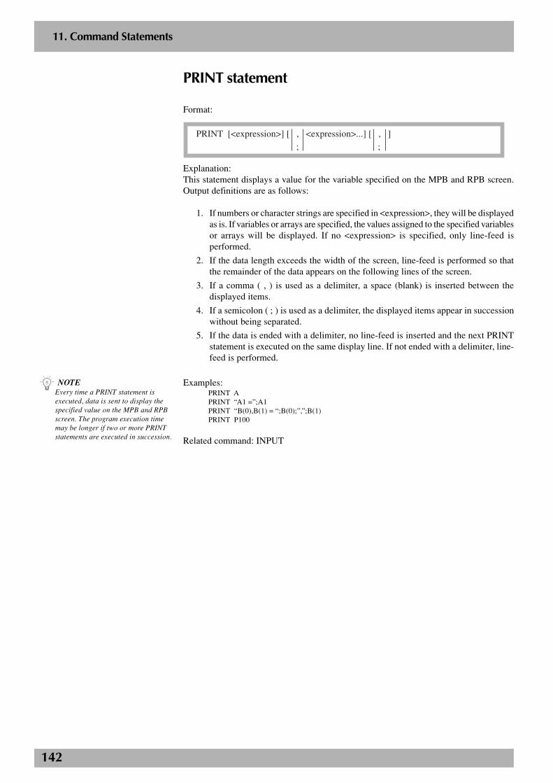
142
2
11. Command Statements
PRINT statement
Format:
PRINT [<expression>] [ , <expression>...] [ , ]
; ;
Explanation:This statement displays a value for the variable specified on the MPB and RPB screen.Output definitions are as follows:
1. If numbers or character strings are specified in <expression>, they will be displayedas is. If variables or arrays are specified, the values assigned to the specified variablesor arrays will be displayed. If no <expression> is specified, only line-feed isperformed.
2. If the data length exceeds the width of the screen, line-feed is performed so thatthe remainder of the data appears on the following lines of the screen.
3. If a comma ( , ) is used as a delimiter, a space (blank) is inserted between thedisplayed items.
4. If a semicolon ( ; ) is used as a delimiter, the displayed items appear in successionwithout being separated.
5. If the data is ended with a delimiter, no line-feed is inserted and the next PRINTstatement is executed on the same display line. If not ended with a delimiter, line-feed is performed.
Examples:PRINT APRINT “A1 =”;A1PRINT “B(0),B(1) = “;B(0);”,”;B(1)PRINT P100
Related command: INPUT
n NOTEEvery time a PRINT statement isexecuted, data is sent to display thespecified value on the MPB and RPBscreen. The program execution timemay be longer if two or more PRINTstatements are executed in succession.
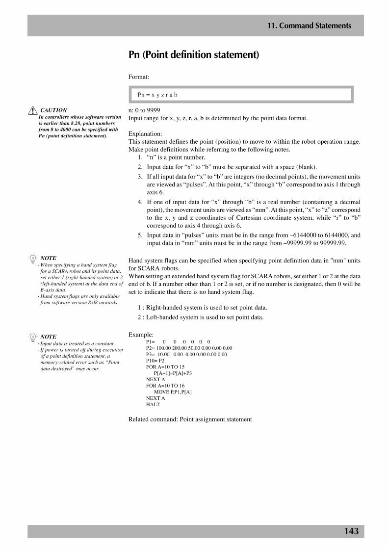
143
2
11. Command Statements
Pn (Point definition statement)
Format:
Pn = x y z r a b
n: 0 to 9999Input range for x, y, z, r, a, b is determined by the point data format.
Explanation:This statement defines the point (position) to move to within the robot operation range.Make point definitions while referring to the following notes.
1. “n” is a point number.
2. Input data for “x” to “b” must be separated with a space (blank).
3. If all input data for “x” to “b” are integers (no decimal points), the movement unitsare viewed as “pulses”. At this point, “x” through “b” correspond to axis 1 throughaxis 6.
4. If one of input data for “x” through “b” is a real number (containing a decimalpoint), the movement units are viewed as “mm”. At this point, “x” to “z” correspondto the x, y and z coordinates of Cartesian coordinate system, while “r” to “b”correspond to axis 4 through axis 6.
5. Input data in “pulses” units must be in the range from –6144000 to 6144000, andinput data in “mm” units must be in the range from –99999.99 to 99999.99.
Hand system flags can be specified when specifying point definition data in "mm" unitsfor SCARA robots.When setting an extended hand system flag for SCARA robots, set either 1 or 2 at the dataend of b. If a number other than 1 or 2 is set, or if no number is designated, then 0 will beset to indicate that there is no hand system flag.
1 : Right-handed system is used to set point data.
2 : Left-handed system is used to set point data.
Example:P1= 0 0 0 0 0 0P2= 100.00 200.00 50.00 0.00 0.00 0.00P3= 10.00 0.00 0.00 0.00 0.00 0.00P10= P2FOR A=10 TO 15
P[A+1]=P[A]+P3NEXT AFOR A=10 TO 16
MOVE P,P1,P[A]NEXT AHALT
Related command: Point assignment statement
n NOTE· Input data is treated as a constant.· If power is turned off during execution
of a point definition statement, amemory-related error such as “Pointdata destroyed” may occur.
c CAUTIONIn controllers whose software versionis earlier than 8.28, point numbersfrom 0 to 4000 can be specified withPn (point definition statement).
n NOTE· When specifying a hand system flag
for a SCARA robot and its point data,set either 1 (right-handed system) or 2(left-handed system) at the data end ofB-axis data.
· Hand system flags are only availablefrom software version 8.08 onwards.
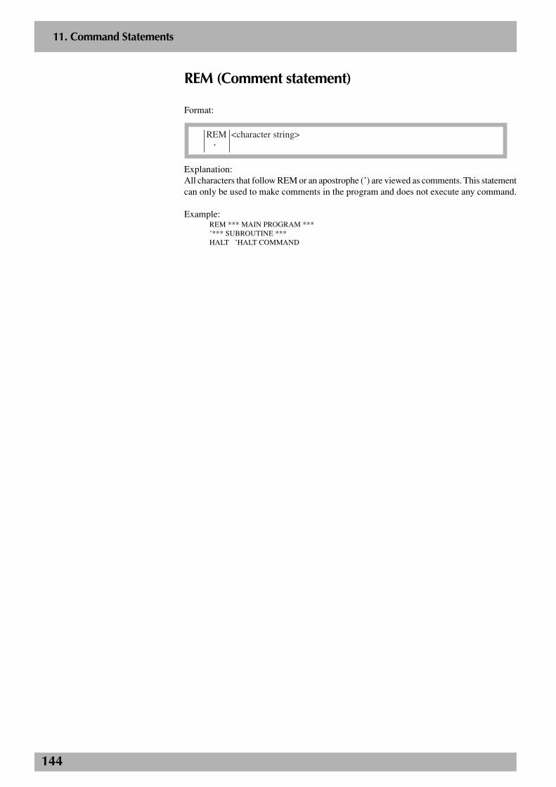
144
2
11. Command Statements
REM (Comment statement)
Format:
REM <character string>
’
Explanation:All characters that follow REM or an apostrophe (’) are viewed as comments. This statementcan only be used to make comments in the program and does not execute any command.
Example:REM *** MAIN PROGRAM ***’*** SUBROUTINE ***HALT ’HALT COMMAND
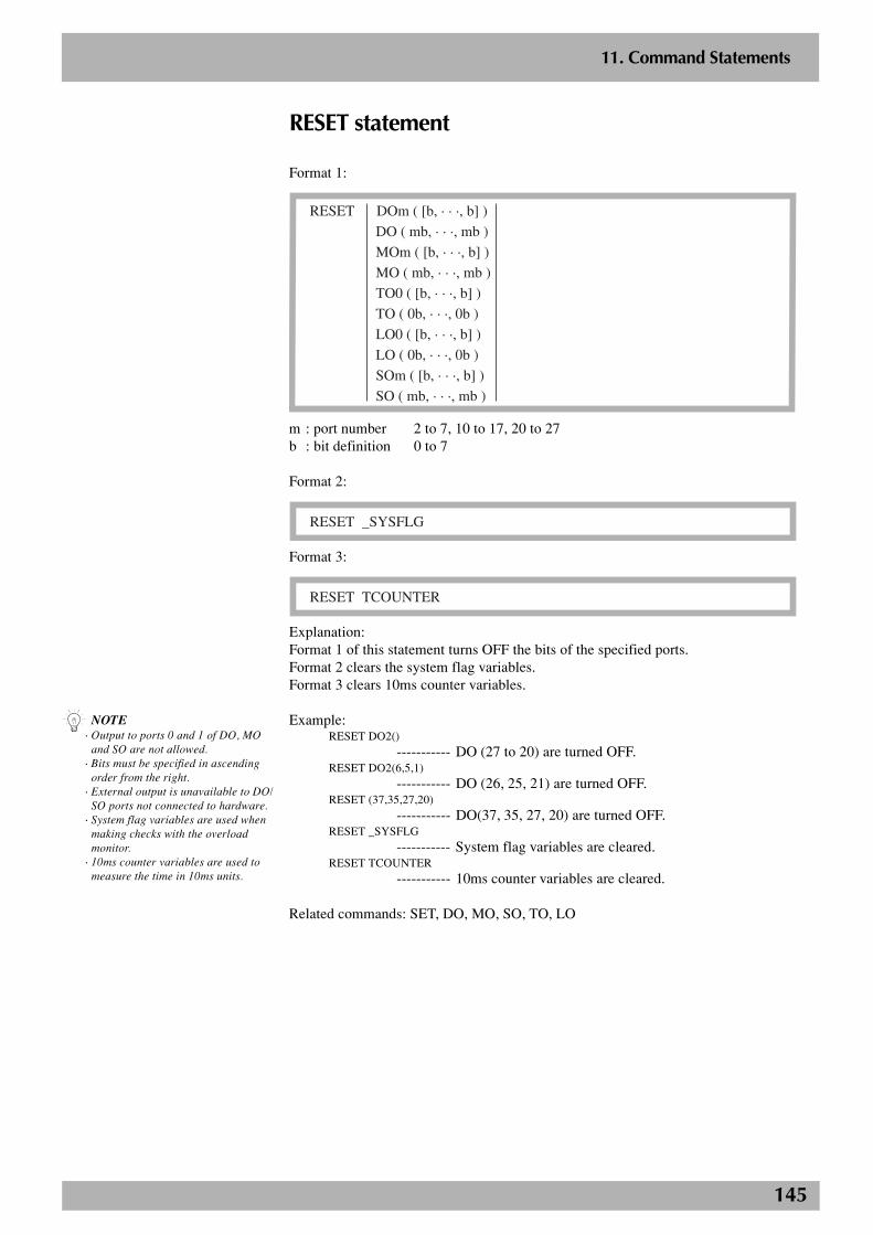
145
2
11. Command Statements
RESET statement
Format 1:
RESET DOm ( [b, · · ·, b] )
DO ( mb, · · ·, mb )
MOm ( [b, · · ·, b] )
MO ( mb, · · ·, mb )
TO0 ( [b, · · ·, b] )
TO ( 0b, · · ·, 0b )
LO0 ( [b, · · ·, b] )
LO ( 0b, · · ·, 0b )
SOm ( [b, · · ·, b] )
SO ( mb, · · ·, mb )
m : port number 2 to 7, 10 to 17, 20 to 27b : bit definition 0 to 7
Format 2:
RESET _SYSFLG
Format 3:
RESET TCOUNTER
Explanation:Format 1 of this statement turns OFF the bits of the specified ports.Format 2 clears the system flag variables.Format 3 clears 10ms counter variables.
Example:RESET DO2()
----------- DO (27 to 20) are turned OFF.RESET DO2(6,5,1)
----------- DO (26, 25, 21) are turned OFF.RESET (37,35,27,20)
----------- DO(37, 35, 27, 20) are turned OFF.RESET _SYSFLG
----------- System flag variables are cleared.RESET TCOUNTER
----------- 10ms counter variables are cleared.
Related commands: SET, DO, MO, SO, TO, LO
n NOTE· Output to ports 0 and 1 of DO, MO
and SO are not allowed.· Bits must be specified in ascending
order from the right.· External output is unavailable to DO/
SO ports not connected to hardware.· System flag variables are used when
making checks with the overloadmonitor.
· 10ms counter variables are used tomeasure the time in 10ms units.
146
2
11. Command Statements
RESTART statement
Format:
RESTART Tn
n : task number 2 to 8
Explanation:This statement restarts another task that is in pause.
Example:START *SUBTASK,T2FLAG=1
*L0:IF FLAG=1 AND DI2(0)=1 THEN
SUSPEND T2FLAG=2WAIT DI2(0)=0
ENDIFIF FLAG=2 AND DI2(0)=1 THEN
RESTART T2FLAG=1WAIT DI2(1)=0
ENDIFMOVE P,P0MOVE P,P1GOTO *L0HALT
’SUBTASK ROUTINE*SUBTASK:DO2(0)=1DELAY 1000DO2(0)=0DELAY 1000GOTO *SUBTASKEXIT TASK
Related commands: CUT, EXIT TASK, START, SUSPEND
147
2
11. Command Statements
RESUME statement
Format:
RESUME [ NEXT ]
<label>
Explanation:This statement resumes the program execution after recovery from an error.There are three ways to resume the program, depending on the location in the program.
1. RESUME The program resumes from the command that caused theerror.
2. RESUME NEXT The program resumes from the command following thecommand that caused the error.
3. RESUME <label> The program resumes from the command specified by<label>.
Example:See the description of the ON ERROR GOTO statement.
Related command: ON ERROR GOTO
n NOTE· The RESUME statement can also be
executed in an error processingroutine.
· Error recovery processing does notwork if the error is serious.
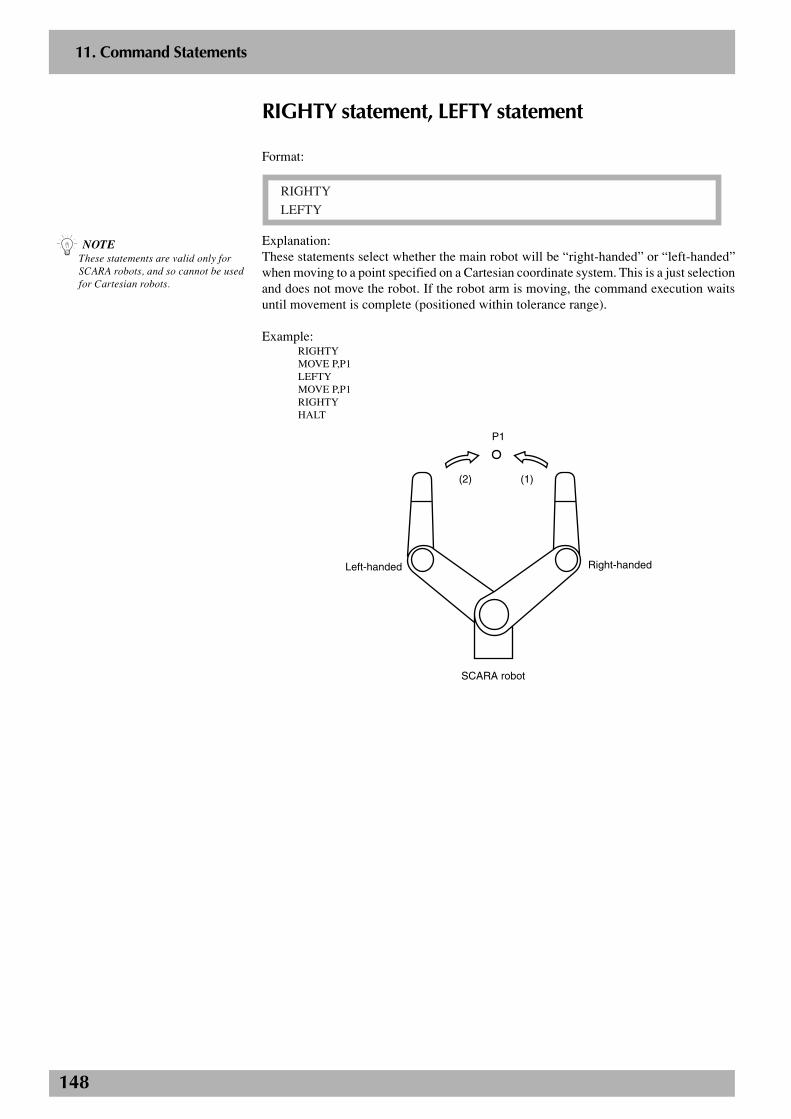
148
2
11. Command Statements
RIGHTY statement, LEFTY statement
Format:
RIGHTY
LEFTY
Explanation:These statements select whether the main robot will be “right-handed” or “left-handed”when moving to a point specified on a Cartesian coordinate system. This is a just selectionand does not move the robot. If the robot arm is moving, the command execution waitsuntil movement is complete (positioned within tolerance range).
Example:RIGHTYMOVE P,P1LEFTYMOVE P,P1RIGHTYHALT
P1
(1)(2)
Left-handed Right-handed
SCARA robot
n NOTEThese statements are valid only forSCARA robots, and so cannot be usedfor Cartesian robots.
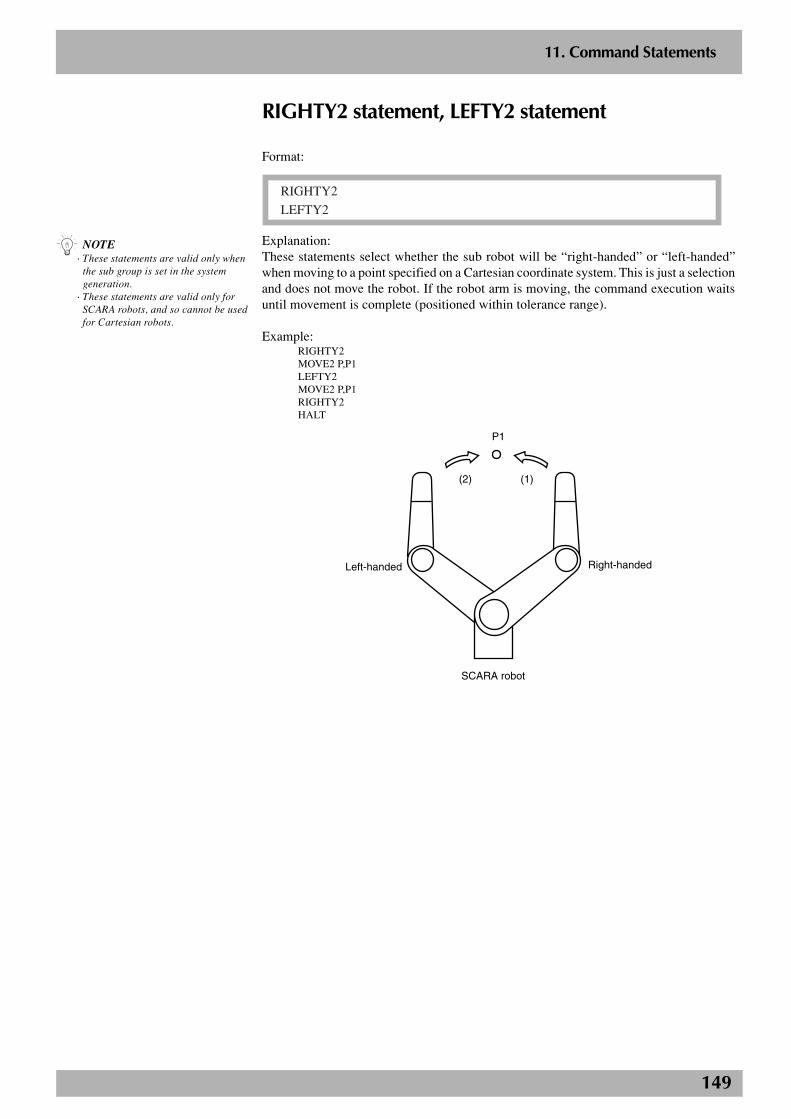
149
2
11. Command Statements
RIGHTY2 statement, LEFTY2 statement
Format:
RIGHTY2
LEFTY2
Explanation:These statements select whether the sub robot will be “right-handed” or “left-handed”when moving to a point specified on a Cartesian coordinate system. This is just a selectionand does not move the robot. If the robot arm is moving, the command execution waitsuntil movement is complete (positioned within tolerance range).
Example:RIGHTY2MOVE2 P,P1LEFTY2MOVE2 P,P1RIGHTY2HALT
P1
(1)(2)
Left-handed Right-handed
SCARA robot
n NOTE· These statements are valid only when
the sub group is set in the systemgeneration.
· These statements are valid only forSCARA robots, and so cannot be usedfor Cartesian robots.
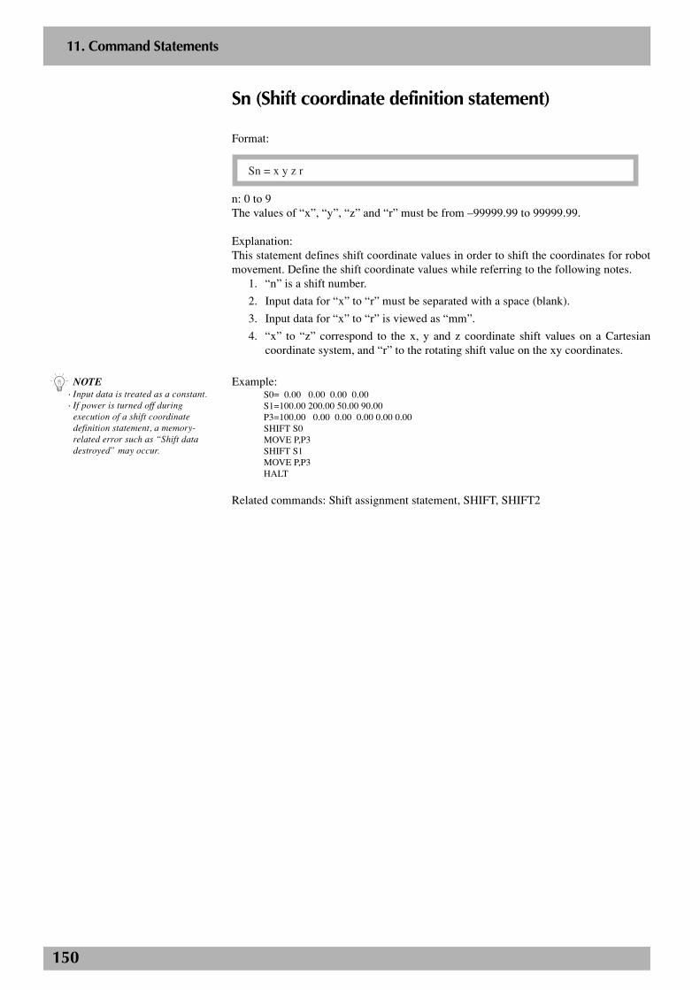
150
2
11. Command Statements
Sn (Shift coordinate definition statement)
Format:
Sn = x y z r
n: 0 to 9The values of “x”, “y”, “z” and “r” must be from –99999.99 to 99999.99.
Explanation:This statement defines shift coordinate values in order to shift the coordinates for robotmovement. Define the shift coordinate values while referring to the following notes.
1. “n” is a shift number.
2. Input data for “x” to “r” must be separated with a space (blank).
3. Input data for “x” to “r” is viewed as “mm”.
4. “x” to “z” correspond to the x, y and z coordinate shift values on a Cartesiancoordinate system, and “r” to the rotating shift value on the xy coordinates.
Example:S0= 0.00 0.00 0.00 0.00S1=100.00 200.00 50.00 90.00P3=100.00 0.00 0.00 0.00 0.00 0.00SHIFT S0MOVE P,P3SHIFT S1MOVE P,P3HALT
Related commands: Shift assignment statement, SHIFT, SHIFT2
n NOTE· Input data is treated as a constant.· If power is turned off during
execution of a shift coordinatedefinition statement, a memory-related error such as “Shift datadestroyed” may occur.
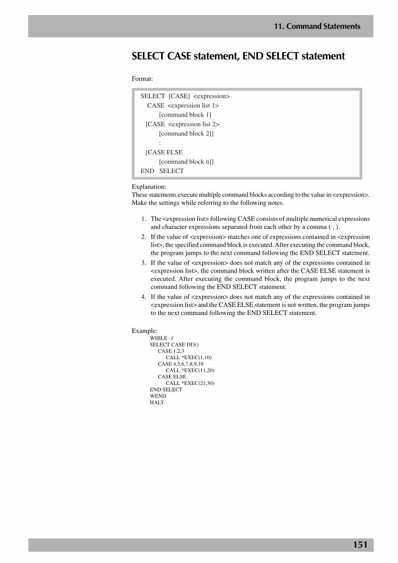
151
2
11. Command Statements
SELECT CASE statement, END SELECT statement
Format:
SELECT [CASE] <expression>
CASE <expression list 1>
[command block 1]
[CASE <expression list 2>
[command block 2]]
:
[CASE ELSE
[command block n]]
END SELECT
Explanation:These statements execute multiple command blocks according to the value in <expression>.Make the settings while referring to the following notes.
1. The <expression list> following CASE consists of multiple numerical expressionsand character expressions separated from each other by a comma ( , ).
2. If the value of <expression> matches one of expressions contained in <expressionlist>, the specified command block is executed. After executing the command block,the program jumps to the next command following the END SELECT statement.
3. If the value of <expression> does not match any of the expressions contained in<expression list>, the command block written after the CASE ELSE statement isexecuted. After executing the command block, the program jumps to the nextcommand following the END SELECT statement.
4. If the value of <expression> does not match any of the expressions contained in<expression list> and the CASE ELSE statement is not written, the program jumpsto the next command following the END SELECT statement.
Example:WHILE -1SELECT CASE DI3()
CASE 1,2,3CALL *EXEC(1,10)
CASE 4,5,6,7,8,9,10CALL *EXEC(11,20)
CASE ELSECALL *EXEC(21,30)
END SELECTWENDHALT
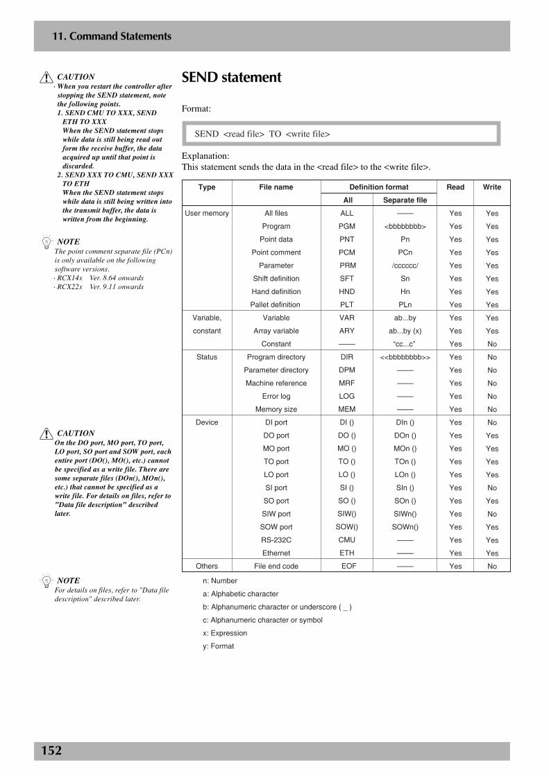
152
2
11. Command Statements
SEND statement
Format:
SEND <read file> TO <write file>
Explanation:This statement sends the data in the <read file> to the <write file>.
Type File name Definition format Read
All Separate file
Write
User memory
Variable,
constant
Status
Device
Others
All files
Program
Point data
Point comment
Parameter
Shift definition
Hand definition
Pallet definition
Variable
Array variable
Constant
Program directory
Parameter directory
Machine reference
Error log
Memory size
DI port
DO port
MO port
TO port
LO port
SI port
SO port
SIW port
SOW port
RS-232C
Ethernet
File end code
ALL
PGM
PNT
PCM
PRM
SFT
HND
PLT
VAR
ARY
––––
DIR
DPM
MRF
LOG
MEM
DI ()
DO ()
MO ()
TO ()
LO ()
SI ()
SO ()
SIW()
SOW()
CMU
ETH
EOF
––––
<bbbbbbbb>
Pn
PCn
/cccccc/
Sn
Hn
PLn
ab...by
ab...by (x)
“cc...c”
<<bbbbbbbb>>
––––
––––
––––
––––
DIn ()
DOn ()
MOn ()
TOn ()
LOn ()
SIn ()
SOn ()
SIWn()
SOWn()
––––
––––
––––
Yes
Yes
Yes
Yes
Yes
Yes
Yes
Yes
Yes
Yes
Yes
Yes
Yes
Yes
Yes
Yes
Yes
Yes
Yes
Yes
Yes
Yes
Yes
Yes
Yes
Yes
Yes
Yes
Yes
Yes
Yes
Yes
Yes
Yes
Yes
Yes
Yes
Yes
No
No
No
No
No
No
No
Yes
Yes
Yes
Yes
No
Yes
No
Yes
Yes
Yes
No
n: Number
a: Alphabetic character
b: Alphanumeric character or underscore ( _ )
c: Alphanumeric character or symbol
x: Expression
y: Format
n NOTEFor details on files, refer to "Data filedescription" described later.
c CAUTION· When you restart the controller after
stopping the SEND statement, notethe following points.1. SEND CMU TO XXX, SEND
ETH TO XXXWhen the SEND statement stopswhile data is still being read outform the receive buffer, the dataacquired up until that point isdiscarded.
2. SEND XXX TO CMU, SEND XXXTO ETHWhen the SEND statement stopswhile data is still being written intothe transmit buffer, the data iswritten from the beginning.
n NOTEThe point comment separate file (PCn)is only available on the followingsoftware versions.· RCX14x Ver. 8.64 onwards· RCX22x Ver. 9.11 onwards
c CAUTIONOn the DO port, MO port, TO port,LO port, SO port and SOW port, eachentire port (DO(), MO(), etc.) cannotbe specified as a write file. There aresome separate files (DOn(), MOn(),etc.) that cannot be specified as awrite file. For details on files, refer to"Data file description" describedlater.

153
2
11. Command Statements
Example:SEND PGM TO CMU
----------- All user programs are output through the RS-232C port.SEND <<PRG1>> TO CMU
----------- The program named “PRG1” is output through the RS-232Cport.
SEND CMU TO PNT
----------- Point data files are input through the RS-232C port.SEND CMU TO P100
----------- Data of point number 100 is input through the RS-232C port.SEND “T1” TO CMU
----------- The character string “T1” is output through the RS-232C port.SEND CMU TO A$
----------- The character string is input to variable A$ through the RS-232C port.
n NOTE· The SEND statement cannot be used
to write onto read-only files.Incorrect examples:
S E N D C M U T O D I RS E N D P N T T O S I ( )
· Even if the read and write files arecorrect, writing cannot be executedunless the data formats match.
Incorrect Examples:S E N D P G M T O P N TS E N D S I ( ) T O S F T
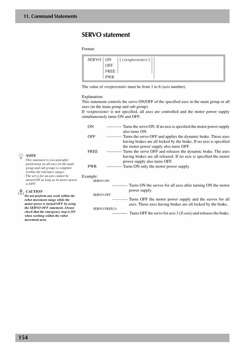
154
2
11. Command Statements
SERVO statement
Format:
SERVO ON [ (<expression>) ]
OFF
FREE
PWR
The value of <expression> must be from 1 to 6 (axis number).
Explanation:This statement controls the servo ON/OFF of the specified axes in the main group or allaxes (in the main group and sub group).If <expression> is not specified, all axes are controlled and the motor power supplysimultaneously turns ON and OFF.
ON ----------- Turns the servo ON. If no axis is specified the motor power supplyalso turns ON.
OFF ----------- Turns the servo OFF and applies the dynamic brake. Those axeshaving brakes are all locked by the brake. If no axis is specifiedthe motor power supply also turns OFF.
FREE ----------- Turns the servo OFF and releases the dynamic brake. The axeshaving brakes are all released. If no axis is specified the motorpower supply also turns OFF.
PWR ----------- Turns ON only the motor power supply.
Example:SERVO ON
----------- Turns ON the servos for all axes after turning ON the motorpower supply.
SERVO OFF
----------- Turns OFF the motor power supply and the servos for allaxes. Those axes having brakes are all locked by the brake.
SERVO FREE(3)
----------- Turns OFF the servo for axis 3 (Z-axis) and releases the brake.
n NOTE· This statement is executed after
positioning on all axes (in the maingroup and sub group) is complete(within the tolerance range).
· The servo for an axis cannot beturned ON as long as its motor poweris OFF.
c CAUTIONDo not perform any work within therobot movement range while themotor power is turned OFF by usingthe SERVO OFF statement. Alwayscheck that the emergency stop is ONwhen working within the robotmovement area.
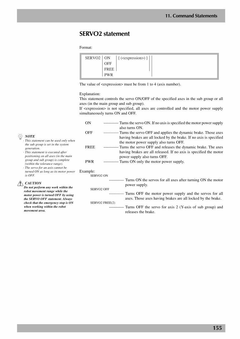
155
2
11. Command Statements
SERVO2 statement
Format:
SERVO2 ON [ (<expression>) ]
OFF
FREE
PWR
The value of <expression> must be from 1 to 4 (axis number).
Explanation:This statement controls the servo ON/OFF of the specified axes in the sub group or allaxes (in the main group and sub group).If <expression> is not specified, all axes are controlled and the motor power supplysimultaneously turns ON and OFF.
ON ----------- Turns the servo ON. If no axis is specified the motor power supplyalso turns ON.
OFF ----------- Turns the servo OFF and applies the dynamic brake. Those axeshaving brakes are all locked by the brake. If no axis is specifiedthe motor power supply also turns OFF.
FREE ----------- Turns the servo OFF and releases the dynamic brake. The axeshaving brakes are all released. If no axis is specified the motorpower supply also turns OFF.
PWR ----------- Turns ON only the motor power supply.
Example:SERVO2 ON
----------- Turns ON the servos for all axes after turning ON the motorpower supply.
SERVO2 OFF
----------- Turns OFF the motor power supply and the servos for allaxes. Those axes having brakes are all locked by the brake.
SERVO2 FREE(2)
----------- Turns OFF the servo for axis 2 (Y-axis of sub group) andreleases the brake.
n NOTE· This statement can be used only when
the sub group is set in the systemgeneration.
· This statement is executed afterpositioning on all axes (in the maingroup and sub group) is complete(within the tolerance range).
· The servo for an axis cannot beturned ON as long as its motor poweris OFF.
c CAUTIONDo not perform any work within therobot movement range while themotor power is turned OFF by usingthe SERVO OFF statement. Alwayscheck that the emergency stop is ONwhen working within the robotmovement area.
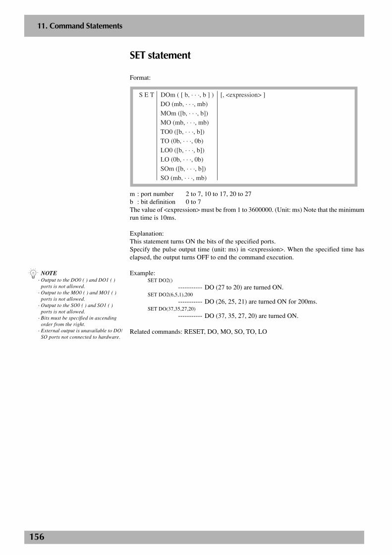
156
2
11. Command Statements
SET statement
Format:
S E T DOm ( [ b, · · ·, b ] ) [, <expression> ]
DO (mb, · · ·, mb)
MOm ([b, · · ·, b])
MO (mb, · · ·, mb)
TO0 ([b, · · ·, b])
TO (0b, · · ·, 0b)
LO0 ([b, · · ·, b])
LO (0b, · · ·, 0b)
SOm ([b, · · ·, b])
SO (mb, · · ·, mb)
m : port number 2 to 7, 10 to 17, 20 to 27b : bit definition 0 to 7The value of <expression> must be from 1 to 3600000. (Unit: ms) Note that the minimumrun time is 10ms.
Explanation:This statement turns ON the bits of the specified ports.Specify the pulse output time (unit: ms) in <expression>. When the specified time haselapsed, the output turns OFF to end the command execution.
Example:SET DO2()
----------- DO (27 to 20) are turned ON.SET DO2(6,5,1),200
----------- DO (26, 25, 21) are turned ON for 200ms.SET DO(37,35,27,20)
----------- DO (37, 35, 27, 20) are turned ON.
Related commands: RESET, DO, MO, SO, TO, LO
n NOTE· Output to the DO0 ( ) and DO1 ( )
ports is not allowed.· Output to the MO0 ( ) and MO1 ( )
ports is not allowed.· Output to the SO0 ( ) and SO1 ( )
ports is not allowed.· Bits must be specified in ascending
order from the right.· External output is unavailable to DO/
SO ports not connected to hardware.
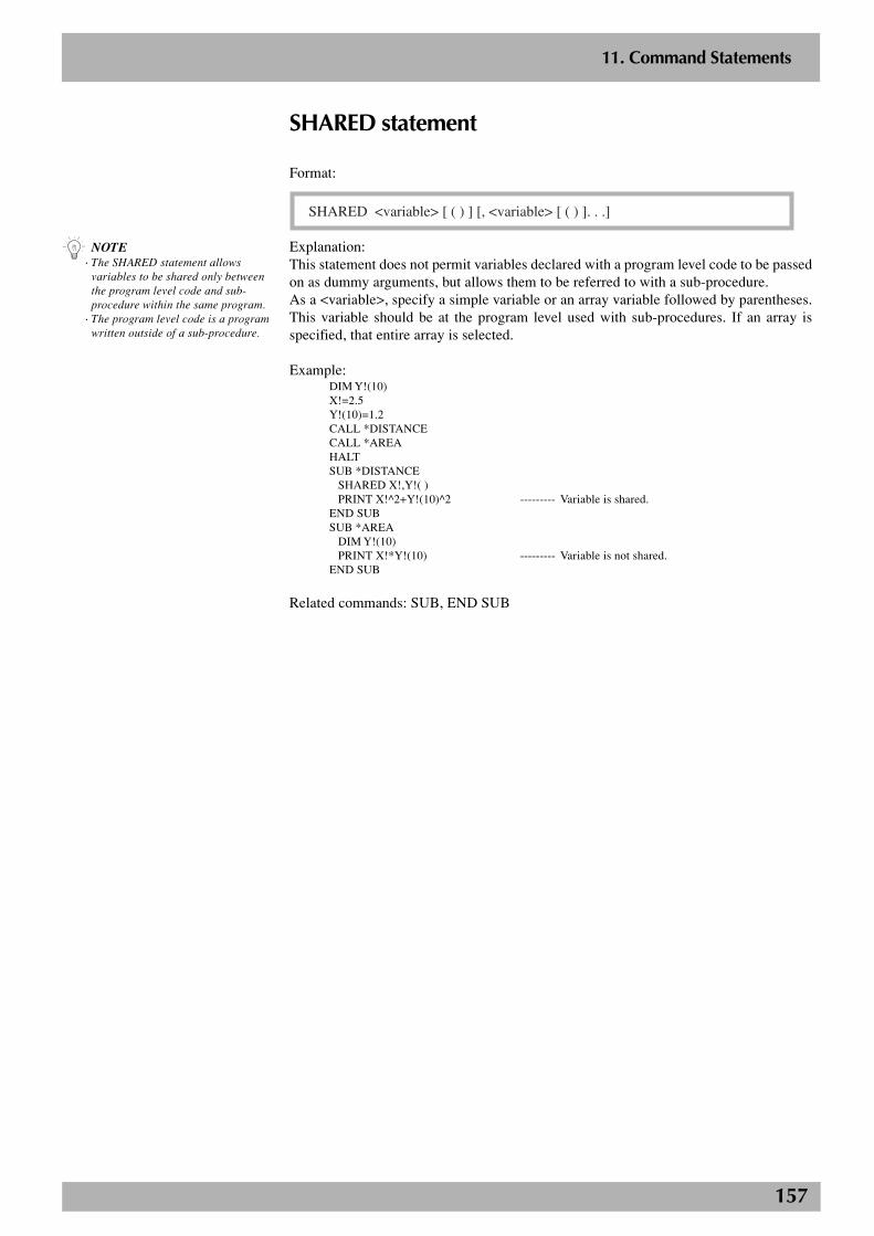
157
2
11. Command Statements
SHARED statement
Format:
SHARED <variable> [ ( ) ] [, <variable> [ ( ) ]. . .]
Explanation:This statement does not permit variables declared with a program level code to be passedon as dummy arguments, but allows them to be referred to with a sub-procedure.As a <variable>, specify a simple variable or an array variable followed by parentheses.This variable should be at the program level used with sub-procedures. If an array isspecified, that entire array is selected.
Example:DIM Y!(10)X!=2.5Y!(10)=1.2CALL *DISTANCECALL *AREAHALTSUB *DISTANCE
SHARED X!,Y!( )PRINT X!^2+Y!(10)^2 --------- Variable is shared.
END SUBSUB *AREA
DIM Y!(10)PRINT X!*Y!(10) --------- Variable is not shared.
END SUB
Related commands: SUB, END SUB
n NOTE· The SHARED statement allows
variables to be shared only betweenthe program level code and sub-procedure within the same program.
· The program level code is a programwritten outside of a sub-procedure.

158
2
11. Command Statements
SHIFT statement(Shift coordinate setting statement for main robot)
Format:
SHIFT <shift variable>
Explanation:This statement sets the shift coordinates for the main robot by using the shift data specifiedin <shift variable>.
Example:SHIFT S1MOVE P,P10SHIFT S[A]MOVE P,P20HALT
Related commands: Shift definition statement, shift assignment statement
n NOTEThis statement is executed afterpositioning on the main robot axes iscomplete (within the tolerance range).
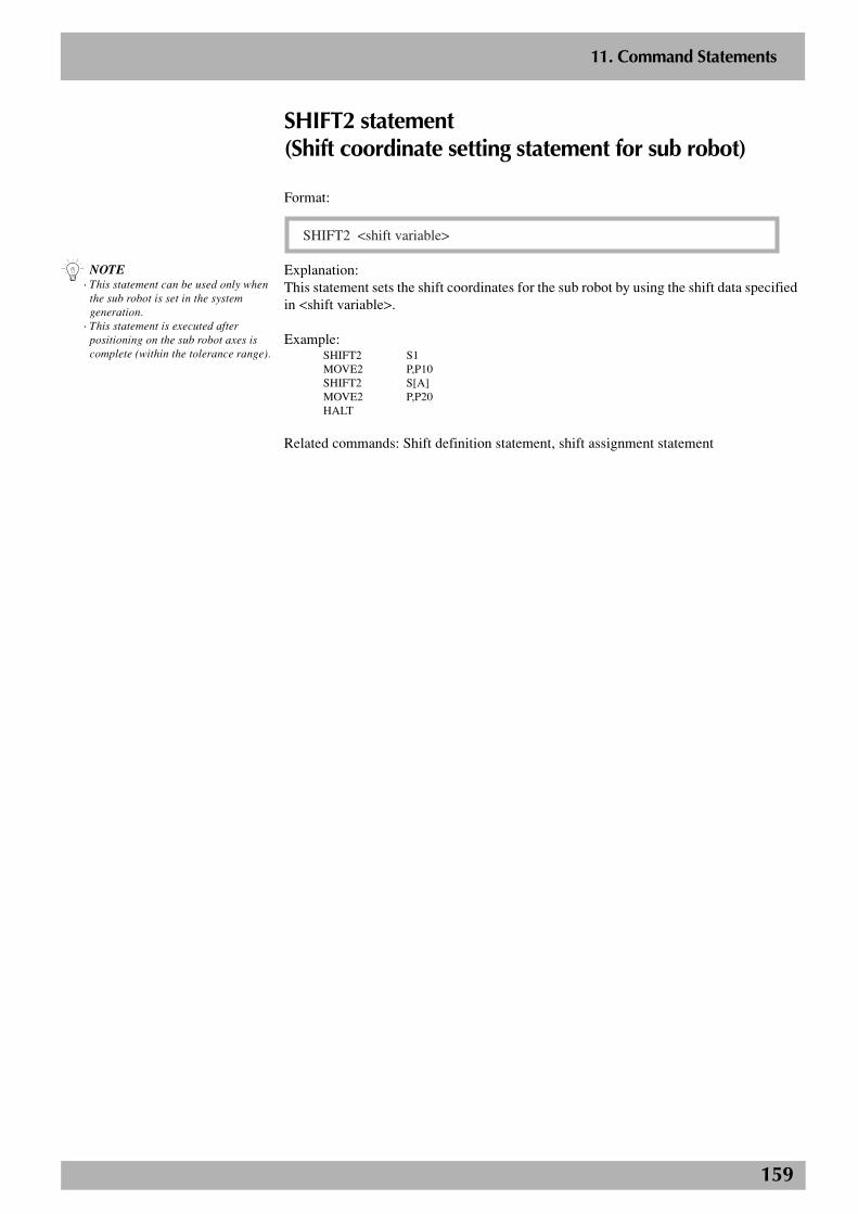
159
2
11. Command Statements
n NOTE· This statement can be used only when
the sub robot is set in the systemgeneration.
· This statement is executed afterpositioning on the sub robot axes iscomplete (within the tolerance range).
SHIFT2 statement(Shift coordinate setting statement for sub robot)
Format:
SHIFT2 <shift variable>
Explanation:This statement sets the shift coordinates for the sub robot by using the shift data specifiedin <shift variable>.
Example:SHIFT2 S1MOVE2 P,P10SHIFT2 S[A]MOVE2 P,P20HALT
Related commands: Shift definition statement, shift assignment statement
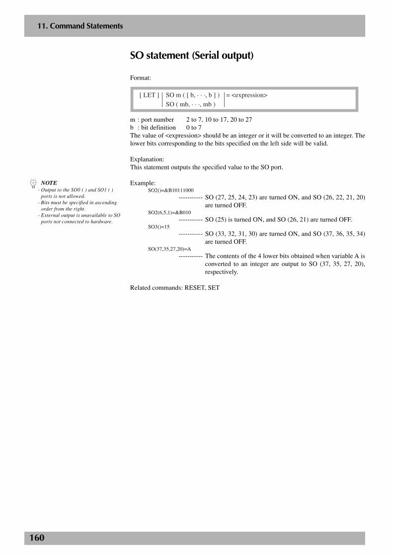
160
2
11. Command Statements
SO statement (Serial output)
Format:
[ LET ] SO m ( [ b, · · ·, b ] ) = <expression>
SO ( mb, · · ·, mb )
m : port number 2 to 7, 10 to 17, 20 to 27b : bit definition 0 to 7The value of <expression> should be an integer or it will be converted to an integer. Thelower bits corresponding to the bits specified on the left side will be valid.
Explanation:This statement outputs the specified value to the SO port.
Example:SO2()=&B10111000
----------- SO (27, 25, 24, 23) are turned ON, and SO (26, 22, 21, 20)are turned OFF.
SO2(6,5,1)=&B010
----------- SO (25) is turned ON, and SO (26, 21) are turned OFF.SO3()=15
----------- SO (33, 32, 31, 30) are turned ON, and SO (37, 36, 35, 34)are turned OFF.
SO(37,35,27,20)=A
----------- The contents of the 4 lower bits obtained when variable A isconverted to an integer are output to SO (37, 35, 27, 20),respectively.
Related commands: RESET, SET
n NOTE· Output to the SO0 ( ) and SO1 ( )
ports is not allowed.· Bits must be specified in ascending
order from the right.· External output is unavailable to SO
ports not connected to hardware.
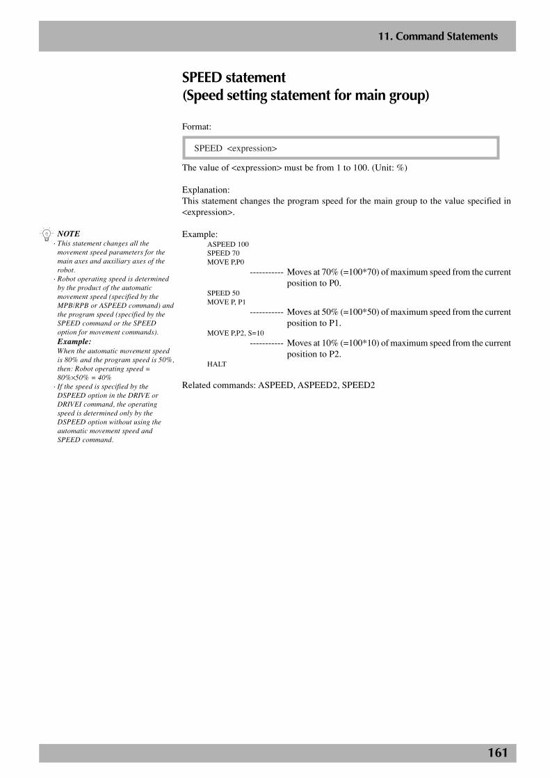
161
2
11. Command Statements
SPEED statement(Speed setting statement for main group)
Format:
SPEED <expression>
The value of <expression> must be from 1 to 100. (Unit: %)
Explanation:This statement changes the program speed for the main group to the value specified in<expression>.
Example:ASPEED 100SPEED 70MOVE P,P0
----------- Moves at 70% (=100*70) of maximum speed from the currentposition to P0.
SPEED 50MOVE P, P1
----------- Moves at 50% (=100*50) of maximum speed from the currentposition to P1.
MOVE P,P2, S=10
----------- Moves at 10% (=100*10) of maximum speed from the currentposition to P2.
HALT
Related commands: ASPEED, ASPEED2, SPEED2
n NOTE· This statement changes all the
movement speed parameters for themain axes and auxiliary axes of therobot.
· Robot operating speed is determinedby the product of the automaticmovement speed (specified by theMPB/RPB or ASPEED command) andthe program speed (specified by theSPEED command or the SPEEDoption for movement commands).Example:When the automatic movement speedis 80% and the program speed is 50%,then: Robot operating speed =80%×50% = 40%
· If the speed is specified by theDSPEED option in the DRIVE orDRIVEI command, the operatingspeed is determined only by theDSPEED option without using theautomatic movement speed andSPEED command.
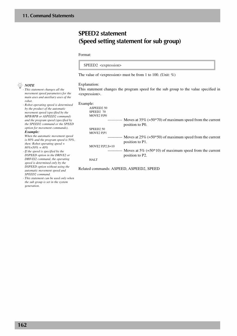
162
2
11. Command Statements
SPEED2 statement(Speed setting statement for sub group)
Format:
SPEED2 <expression>
The value of <expression> must be from 1 to 100. (Unit: %)
Explanation:This statement changes the program speed for the sub group to the value specified in<expression>.
Example:ASPEED2 50SPEED2 70MOVE2 P,P0
----------- Moves at 35% (=50*70) of maximum speed from the currentposition to P0.
SPEED2 50MOVE2 P,P1
----------- Moves at 25% (=50*50) of maximum speed from the currentposition to P1.
MOVE2 P,P2,S=10
----------- Moves at 5% (=50*10) of maximum speed from the currentposition to P2.
HALT
Related commands: ASPEED, ASPEED2, SPEED
n NOTE· This statement changes all the
movement speed parameters for themain axes and auxiliary axes of therobot.
· Robot operating speed is determinedby the product of the automaticmovement speed (specified by theMPB/RPB or ASPEED2 command)and the program speed (specified bythe SPEED2 command or the SPEEDoption for movement commands).Example:When the automatic movement speedis 80% and the program speed is 50%,then: Robot operating speed =80%×50% = 40%
· If the speed is specified by theDSPEED option in the DRIVE2 orDRIVEI2 command, the operatingspeed is determined only by theDSPEED option without using theautomatic movement speed andSPEED2 command.
· This statement can be used only whenthe sub group is set in the systemgeneration.
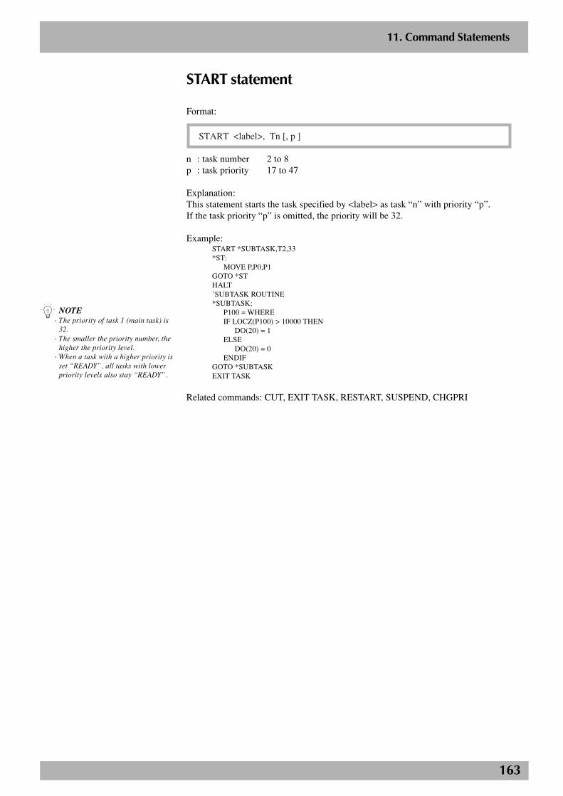
163
2
11. Command Statements
START statement
Format:
START <label>, Tn [, p ]
n : task number 2 to 8p : task priority 17 to 47
Explanation:This statement starts the task specified by <label> as task “n” with priority “p”.If the task priority “p” is omitted, the priority will be 32.
Example:START *SUBTASK,T2,33*ST:
MOVE P,P0,P1GOTO *STHALT’SUBTASK ROUTINE*SUBTASK:
P100 = WHEREIF LOCZ(P100) > 10000 THEN
DO(20) = 1ELSE
DO(20) = 0ENDIF
GOTO *SUBTASKEXIT TASK
Related commands: CUT, EXIT TASK, RESTART, SUSPEND, CHGPRI
n NOTE· The priority of task 1 (main task) is
32.· The smaller the priority number, the
higher the priority level.· When a task with a higher priority is
set “READY”, all tasks with lowerpriority levels also stay “READY”.
164
2
11. Command Statements
SUB statement, END SUB statement
Format:
SUB <label> [ ( <dummy argument> [, <dummy argument> . . . ] ) ] <command block>END SUB
Explanation:The SUB statement and END SUB statement define a sub-procedure that can be executedwith the CALL statement. When the END SUB statement is executed, the program jumpsto the next command in the CALL statement that was called. Defines are shown below.
1. All variables declared within the sub-procedure are local variables so they arevalid only within the sub-procedure. Local variables are initialized each time thesub-procedure is called up.
2. Use a SHARED statement when using global variables (program level).
3. Use <dummy argument> when variables are to be passed on. If two or more dummyarguments are used, separate them by a comma ( , ).
4. A valid <dummy argument> consists of a name of variable and an entire array(array name followed by parentheses).
n NOTE· Sub-procedures cannot be defined
within a sub-procedure.· The DECLARE statement cannot be
used within a sub-procedure.· A label can be defined within a sub-
procedure, but it cannot jump with aGOTO or GOSUB statement to a labeloutside the sub-procedure.
· Sub-procedures cannot be used withinan expression.
· Local variables cannot be used withPRINT and SEND statements.
165
2
11. Command Statements
Example 1:
I=1CALL *TESTPRINT IHALT’SUB ROUTINE: TESTSUB *TEST
I=50END SUB
In the above example, the program level variable I does not have any relation tovariable I within the sub-procedure. The value displayed with the PRINT statementon the third line will be “1”.
Example 2:X% = 4Y% = 5CALL *COMPARE( REF X%, REF Y% )PRINT X%,Y%Z% = 7W% = 2CALL *COMPARE( REF Z%, REF W% )PRINT Z%,W%HALT’SUB ROUTINE: COMPARESUB *COMPARE( A%, B% )
IF A% < B% THENTEMP% = A%A% = B%B% = TEMP%
ENDIFEND SUB
In the above example, different variables are passed on as arguments to call up thesub-procedure twice.
Related commands: CALL, DECLARE, EXIT SUB, SHARED
166
2
11. Command Statements
SUSPEND statement
Format:
SUSPEND Tn
n: task number 2 to 8
Explanation:This statement temporarily stops another task being executed.
Examples:START *SUBTASK,T2SUSFLG=0
*L0:MOVE P,P0MOVE P,P1WAIT SUSFLG=1SUSPEND T2SUSFLG=0
GOTO *L0HALT
’SUBTASK ROUTINE*SUBTASK:
WAIT SUSFLG=0DO2(0)=1DELAY 1000DO2(0)=0DELAY 1000SUSFLG=1GOTO *SUBTASKEXIT TASK
Related commands: CUT, EXIT TASK, RESTART, SUSPEND
167
2
11. Command Statements
SWI statement
This statement switches the execution program.
Format:
SWI <program name>
Explanation:This statement switches from the current program to the specified program, starting fromthe first line after executing compiling. The output variable status does not change whenthe program was switched. However, dynamic variables and array variables are cleared.If an error occurs during compiling, the operation stops. The program name you want toswitch to must be enclosed in < >.
Example:SWI <ABC>
----------- The execution program switches to <ABC>.
n NOTE· If there is no program to switch to,
then the message “3.3: Programdoesn't exist” appears and operationstops.
· If an error occurs during compiling,an error message line is displayedand the program stops.
· The SWI statement can only beexecuted within task 1 (main task).If used within tasks 2 through 8, themessage “6.1:Illegal command”appears and operation stops.
· The Stop key does not function duringcompiling.
· Execution of a SWI statement isalways accompanied by compiling,and the time required for thiscompiling depends on the size ofprogram to switch to.
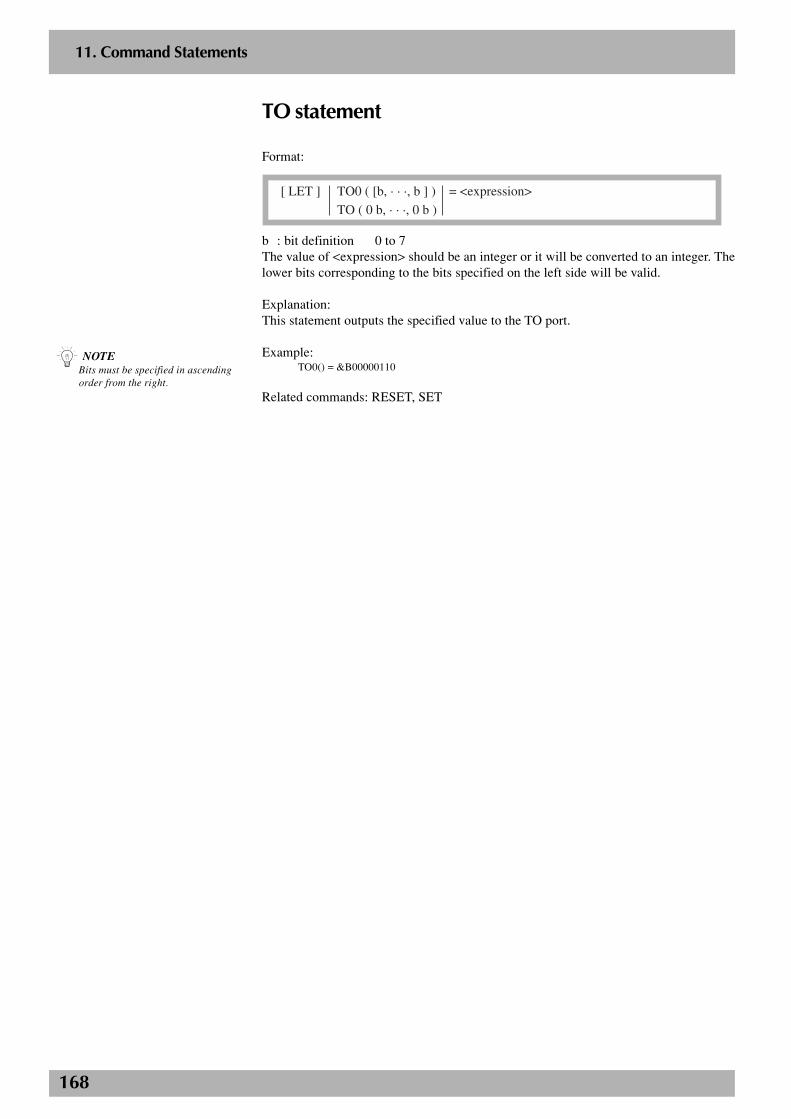
168
2
11. Command Statements
TO statement
Format:
[ LET ] TO0 ( [b, · · ·, b ] ) = <expression>
TO ( 0 b, · · ·, 0 b )
b : bit definition 0 to 7The value of <expression> should be an integer or it will be converted to an integer. Thelower bits corresponding to the bits specified on the left side will be valid.
Explanation:This statement outputs the specified value to the TO port.
Example:TO0() = &B00000110
Related commands: RESET, SET
n NOTEBits must be specified in ascendingorder from the right.

169
2
11. Command Statements
TOLE statement(Tolerance setting statement for main group)
Format 1:
TOLE <expression>
Format 2:
TOLE ( <expression 1> ) = <expression 2>
The value of <expression 1> must be from 1 to 6 (axis number).The values of <expression> and <expression 2> differ depending on the motor. (Unit:pulses)
Explanation:This statement changes the tolerance parameter for the main group to the value specifiedin <expression>. Format 1 changes all axes in the main group. Format 2 changes thetolerance parameter for the main group axis specified in <expression 1> to the valuespecified in <expression 2>.
Example:’CYCLE WITH DECREASING TOLERANCEFOR A=100 TO 20 STEP -20GOSUB *CHANGE_TOLEMOVE P,P0MOVE P,P1NEXT AHALT
*CHANGE_TOLE:FOR B=1 TO 4TOLE(B)=ANEXT BRETURN
n NOTE· If an axis that is set to “no axis” in
the system generation is specified,then an error message “Specificationmismatch” appears and execution ofthe command will stop.
· This statement is executed afterpositioning on the specified axes iscomplete (within the tolerance range).
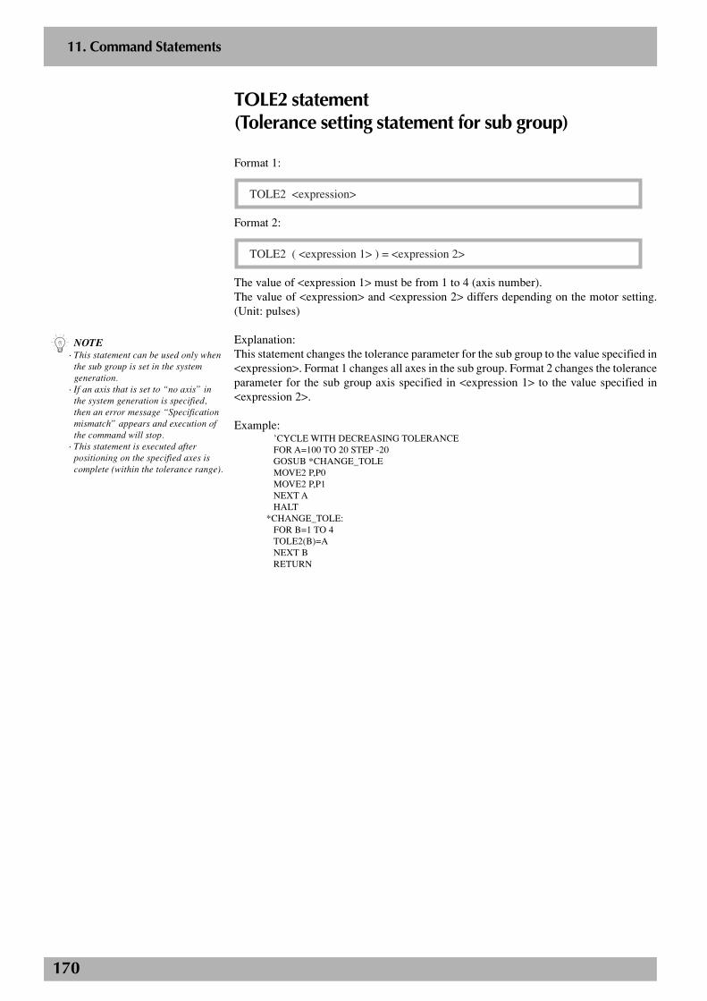
170
2
11. Command Statements
TOLE2 statement(Tolerance setting statement for sub group)
Format 1:
TOLE2 <expression>
Format 2:
TOLE2 ( <expression 1> ) = <expression 2>
The value of <expression 1> must be from 1 to 4 (axis number).The value of <expression> and <expression 2> differs depending on the motor setting.(Unit: pulses)
Explanation:This statement changes the tolerance parameter for the sub group to the value specified in<expression>. Format 1 changes all axes in the sub group. Format 2 changes the toleranceparameter for the sub group axis specified in <expression 1> to the value specified in<expression 2>.
Example:’CYCLE WITH DECREASING TOLERANCEFOR A=100 TO 20 STEP -20GOSUB *CHANGE_TOLEMOVE2 P,P0MOVE2 P,P1NEXT AHALT
*CHANGE_TOLE:FOR B=1 TO 4TOLE2(B)=ANEXT BRETURN
n NOTE· This statement can be used only when
the sub group is set in the systemgeneration.
· If an axis that is set to “no axis” inthe system generation is specified,then an error message “Specificationmismatch” appears and execution ofthe command will stop.
· This statement is executed afterpositioning on the specified axes iscomplete (within the tolerance range).
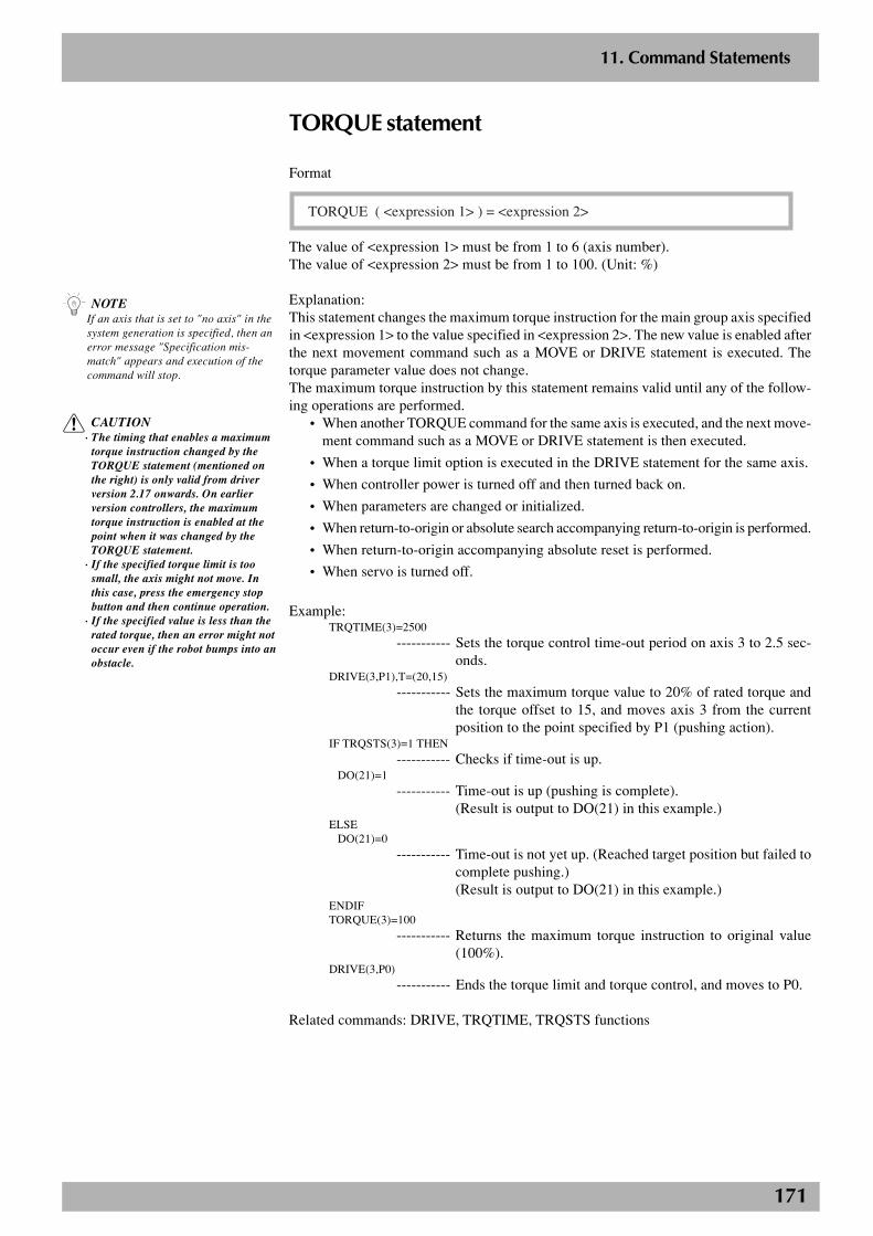
171
2
11. Command Statements
TORQUE statement
Format
TORQUE ( <expression 1> ) = <expression 2>
The value of <expression 1> must be from 1 to 6 (axis number).The value of <expression 2> must be from 1 to 100. (Unit: %)
Explanation:This statement changes the maximum torque instruction for the main group axis specifiedin <expression 1> to the value specified in <expression 2>. The new value is enabled afterthe next movement command such as a MOVE or DRIVE statement is executed. Thetorque parameter value does not change.The maximum torque instruction by this statement remains valid until any of the follow-ing operations are performed.
• When another TORQUE command for the same axis is executed, and the next move-ment command such as a MOVE or DRIVE statement is then executed.
• When a torque limit option is executed in the DRIVE statement for the same axis.
• When controller power is turned off and then turned back on.
• When parameters are changed or initialized.
• When return-to-origin or absolute search accompanying return-to-origin is performed.
• When return-to-origin accompanying absolute reset is performed.
• When servo is turned off.
Example:TRQTIME(3)=2500
----------- Sets the torque control time-out period on axis 3 to 2.5 sec-onds.
DRIVE(3,P1),T=(20,15)
----------- Sets the maximum torque value to 20% of rated torque andthe torque offset to 15, and moves axis 3 from the currentposition to the point specified by P1 (pushing action).
IF TRQSTS(3)=1 THEN----------- Checks if time-out is up.
DO(21)=1----------- Time-out is up (pushing is complete).
(Result is output to DO(21) in this example.)ELSE
DO(21)=0
----------- Time-out is not yet up. (Reached target position but failed tocomplete pushing.)(Result is output to DO(21) in this example.)
ENDIFTORQUE(3)=100
----------- Returns the maximum torque instruction to original value(100%).
DRIVE(3,P0)
----------- Ends the torque limit and torque control, and moves to P0.
Related commands: DRIVE, TRQTIME, TRQSTS functions
n NOTEIf an axis that is set to "no axis" in thesystem generation is specified, then anerror message "Specification mis-match" appears and execution of thecommand will stop.
c CAUTION· The timing that enables a maximum
torque instruction changed by theTORQUE statement (mentioned onthe right) is only valid from driverversion 2.17 onwards. On earlierversion controllers, the maximumtorque instruction is enabled at thepoint when it was changed by theTORQUE statement.
· If the specified torque limit is toosmall, the axis might not move. Inthis case, press the emergency stopbutton and then continue operation.
· If the specified value is less than therated torque, then an error might notoccur even if the robot bumps into anobstacle.
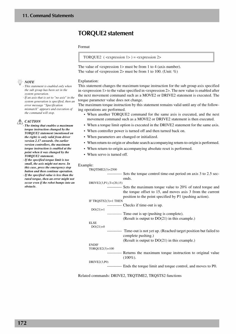
172
2
11. Command Statements
TORQUE2 statement
Format
TORQUE2 ( <expression 1> ) = <expression 2>
The value of <expression 1> must be from 1 to 4 (axis number).The value of <expression 2> must be from 1 to 100. (Unit: %)
Explanation:This statement changes the maximum torque instruction for the sub group axis specifiedin <expression 1> to the value specified in <expression 2>. The new value is enabled afterthe next movement command such as a MOVE2 or DRIVE2 statement is executed. Thetorque parameter value does not change.The maximum torque instruction by this statement remains valid until any of the follow-ing operations are performed.
• When another TORQUE2 command for the same axis is executed, and the nextmovement command such as a MOVE2 or DRIVE2 statement is then executed.
• When a torque limit option is executed in the DRIVE2 statement for the same axis.
• When controller power is turned off and then turned back on.
• When parameters are changed or initialized.
• When return-to-origin or absolute search accompanying return-to-origin is performed.
• When return-to-origin accompanying absolute reset is performed.
• When servo is turned off.
Example:TRQTIME2(3)=2500
----------- Sets the torque control time-out period on axis 3 to 2.5 sec-onds.
DRIVE2(3,P1),T=(20,15)
----------- Sets the maximum torque value to 20% of rated torque andthe torque offset to 15, and moves axis 3 from the currentposition to the point specified by P1 (pushing action).
IF TRQSTS2(3)=1 THEN----------- Checks if time-out is up.
DO(21)=1----------- Time-out is up (pushing is complete).
(Result is output to DO(21) in this example.)ELSE
DO(21)=0
----------- Time-out is not yet up. (Reached target position but failed tocomplete pushing.)(Result is output to DO(21) in this example.)
ENDIFTORQUE2(3)=100
----------- Returns the maximum torque instruction to original value(100%).
DRIVE2(3,P0)
----------- Ends the torque limit and torque control, and moves to P0.
Related commands: DRIVE2, TRQTIME2, TRQSTS2 functions
n NOTE· This statement is enabled only when
the sub group has been set in thesystem generation.
· If an axis that is set to "no axis" in thesystem generation is specified, then anerror message “Specificationmismatch” appears and execution ofthe command will stop.
c CAUTION· The timing that enables a maximum
torque instruction changed by theTORQUE2 statement (mentioned onthe right) is only valid from driverversion 2.17 onwards. On earlierversion controllers, the maximumtorque instruction is enabled at thepoint when it was changed by theTORQUE2 statement.
· If the specified torque limit is toosmall, the axis might not move. Inthis case, press the emergency stopbutton and then continue operation.
· If the specified value is less than therated torque, then an error might notoccur even if the robot bumps into anobstacle.
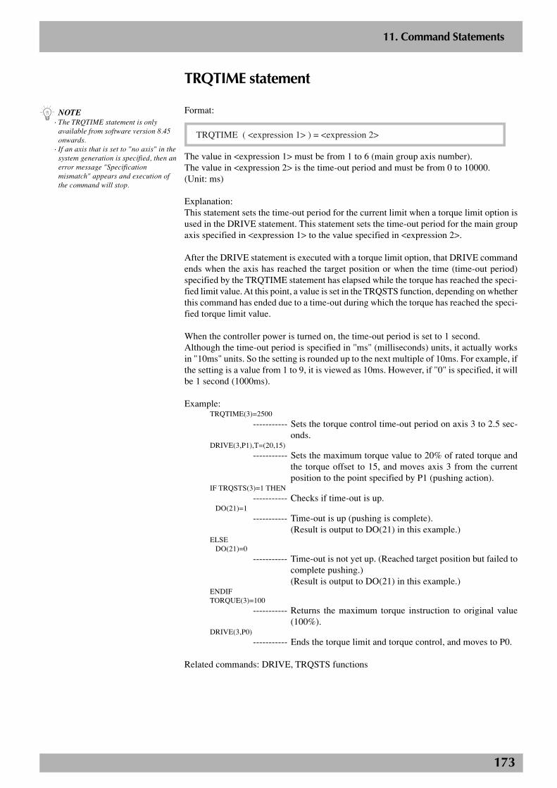
173
2
11. Command Statements
TRQTIME statement
Format:
TRQTIME ( <expression 1> ) = <expression 2>
The value in <expression 1> must be from 1 to 6 (main group axis number).The value in <expression 2> is the time-out period and must be from 0 to 10000.(Unit: ms)
Explanation:This statement sets the time-out period for the current limit when a torque limit option isused in the DRIVE statement. This statement sets the time-out period for the main groupaxis specified in <expression 1> to the value specified in <expression 2>.
After the DRIVE statement is executed with a torque limit option, that DRIVE commandends when the axis has reached the target position or when the time (time-out period)specified by the TRQTIME statement has elapsed while the torque has reached the speci-fied limit value. At this point, a value is set in the TRQSTS function, depending on whetherthis command has ended due to a time-out during which the torque has reached the speci-fied torque limit value.
When the controller power is turned on, the time-out period is set to 1 second.Although the time-out period is specified in "ms" (milliseconds) units, it actually worksin "10ms" units. So the setting is rounded up to the next multiple of 10ms. For example, ifthe setting is a value from 1 to 9, it is viewed as 10ms. However, if "0" is specified, it willbe 1 second (1000ms).
Example:TRQTIME(3)=2500
----------- Sets the torque control time-out period on axis 3 to 2.5 sec-onds.
DRIVE(3,P1),T=(20,15)
----------- Sets the maximum torque value to 20% of rated torque andthe torque offset to 15, and moves axis 3 from the currentposition to the point specified by P1 (pushing action).
IF TRQSTS(3)=1 THEN
----------- Checks if time-out is up.DO(21)=1
----------- Time-out is up (pushing is complete).(Result is output to DO(21) in this example.)
ELSEDO(21)=0
----------- Time-out is not yet up. (Reached target position but failed tocomplete pushing.)(Result is output to DO(21) in this example.)
ENDIFTORQUE(3)=100
----------- Returns the maximum torque instruction to original value(100%).
DRIVE(3,P0)
----------- Ends the torque limit and torque control, and moves to P0.
Related commands: DRIVE, TRQSTS functions
n NOTE· The TRQTIME statement is only
available from software version 8.45onwards.
· If an axis that is set to "no axis" in thesystem generation is specified, then anerror message "Specificationmismatch" appears and execution ofthe command will stop.
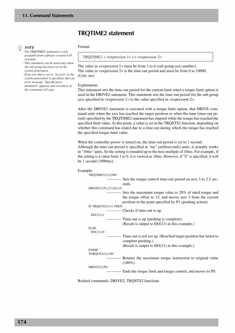
174
2
11. Command Statements
TRQTIME2 statement
Format:
TRQTIME2 ( <expression 1> ) = <expression 2>
The value in <expression 1> must be from 1 to 6 (sub group axis number).The value in <expression 2> is the time-out period and must be from 0 to 10000.(Unit: ms)
Explanation:This statement sets the time-out period for the current limit when a torque limit option isused in the DRIVE2 statement. This statement sets the time-out period for the sub groupaxis specified in <expression 1> to the value specified in <expression 2>.
After the DRIVE2 statement is executed with a torque limit option, that DRIVE com-mand ends when the axis has reached the target position or when the time (time-out pe-riod) specified by the TRQTIME2 statement has elapsed while the torque has reached thespecified limit value. At this point, a value is set in the TRQSTS2 function, depending onwhether this command has ended due to a time-out during which the torque has reachedthe specified torque limit value.
When the controller power is turned on, the time-out period is set to 1 second.Although the time-out period is specified in "ms" (milliseconds) units, it actually worksin "10ms" units. So the setting is rounded up to the next multiple of 10ms. For example, ifthe setting is a value from 1 to 9, it is viewed as 10ms. However, if "0" is specified, it willbe 1 second (1000ms).
Example:TRQTIME2(3)=2500
----------- Sets the torque control time-out period on axis 3 to 2.5 sec-onds.
DRIVE2(3,P1),T=(20,15)
----------- Sets the maximum torque value to 20% of rated torque andthe torque offset to 15, and moves axis 3 from the currentposition to the point specified by P1 (pushing action).
IF TRQSTS2(3)=1 THEN
----------- Checks if time-out is up.DO(21)=1
----------- Time-out is up (pushing is complete).(Result is output to DO(21) in this example.)
ELSEDO(21)=0
----------- Time-out is not yet up. (Reached target position but failed tocomplete pushing.)(Result is output to DO(21) in this example.)
ENDIFTORQUE2(3)=100
----------- Returns the maximum torque instruction to original value(100%).
DRIVE2(3,P0)
----------- Ends the torque limit and torque control, and moves to P0.
Related commands: DRIVE2, TRQSTS2 functions
n NOTE· The TRQTIME2 statement is only
available from software version 8.45onwards.
· This statement can be used only whenthe sub group has been set in thesystem generation.
· If an axis that is set to "no axis" in thesystem generation is specified, then anerror message "Specificationmismatch" appears and execution ofthe command will stop.
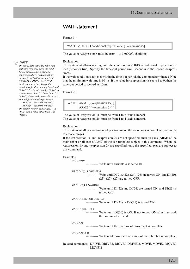
175
2
11. Command Statements
WAIT statement
Format 1:
WAIT < DI / DO conditional expression> [, <expression>]
The value of <expression> must be from 1 to 3600000. (Unit: ms)
Explanation:This statement allows waiting until the condition in <DI/DO conditional expression> ismet (becomes true). Specify the time-out period (milliseconds) in the second <expres-sion>.If the wait condition is not met within the time-out period, the command terminates. Notethat the minimum wait time is 10 ms. If the value in <expression> is set to 1 to 9, then thetime-out period is viewed as 10ms.
Format 2:WAIT ARMWAIT ARM2
WAIT ARM [ (<expression 1>) ]
ARM2 [ (<expression 2>) ]
The value of <expression 1> must be from 1 to 6 (axis number).The value of <expression 2> must be from 1 to 4 (axis number).
Explanation:This statement allows waiting until positioning on the robot axes is complete (within thetolerance range).If the <expression 1> and <expression 2> are not specified, then all axes (ARM) of themain robot or all axes (ARM2) of the sub robot are subject to this command. When the<expression 1> and <expression 2> are specified, only the specified axes are subject tothis command.
Examples:WAIT A=10
----------- Waits until variable A is set to 10.
WAIT DI2( )=&B01010110
----------- Waits until DI(21), (22), (24), (26) are turned ON, and DI(20),(23), (25), (27) are turned OFF.
WAIT DI2(4,3,2)=&B101----------- Waits until DI(22) and DI(24) are turned ON, and DI(23) is
turned OFF.
WAIT DI(31)=1 OR DO(21)=1
----------- Waits until DI(31) or DO(21) is turned ON.
WAIT DI(20)=1,1000----------- Waits until DI(20) is ON. If not turned ON after 1 second,
the command will end.
WAIT ARM----------- Waits until the main robot movement is complete.
WAIT ARM2(2)----------- Waits until movement on axis 2 of the sub robot is complete.
Related commands: DRIVE, DRIVE2, DRIVEI, DRIVEI2, MOVE, MOVE2, MOVEI,MOVEI2
n NOTEOn controllers using the followingsoftware versions, when the condi-tional expression is a numericexpression, the "TRUE condition"parameter of "Other parameters"(SYSTEM > PARAM > OTHERSmode) can be set to change theconditions for determining "true" and"false" (-1 is "true" and 0 is "false", ora value other than 0 is "true" and 0 is"false"). Refer to the controller user'smanual for detailed information.
RCX14x Ver. 8.63 onwards,RCX22x Ver. 9.08 onwards
On earlier version controllers, -1 is"true" and a value other than -1 is"false".
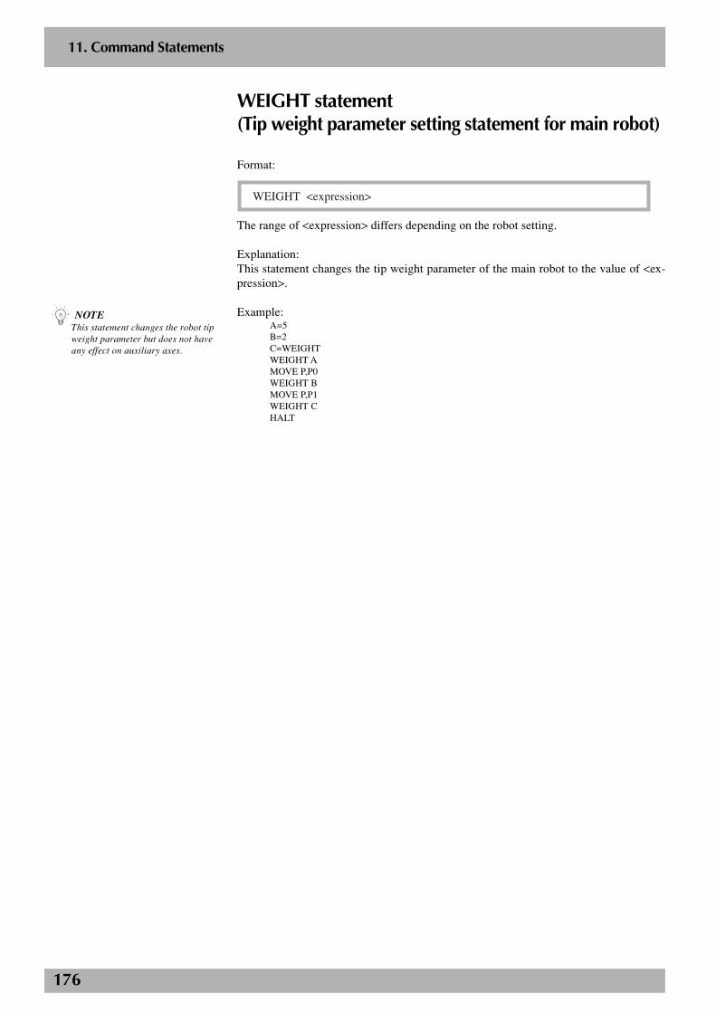
176
2
11. Command Statements
WEIGHT statement(Tip weight parameter setting statement for main robot)
Format:
WEIGHT <expression>
The range of <expression> differs depending on the robot setting.
Explanation:This statement changes the tip weight parameter of the main robot to the value of <ex-pression>.
Example:A=5B=2C=WEIGHTWEIGHT AMOVE P,P0WEIGHT BMOVE P,P1WEIGHT CHALT
n NOTEThis statement changes the robot tipweight parameter but does not haveany effect on auxiliary axes.
177
2
11. Command Statements
WEIGHT2 statement(Tip weight parameter setting statement for sub robot)
Format:
WEIGHT2 <expression>
The range of <expression> differs depending on the robot setting.
Explanation:This statement changes the tip weight parameter of the sub robot to the value of <expres-sion>.
Example:A=5B=2C=WEIGHT2WEIGHT2 AMOVE2 P,P0WEIGHT2 BMOVE2 P,P1WEIGHT2 CHALT
n NOTE· This statement can be used only when
the sub robot is set in the systemgeneration.
· This statement changes the robot tipweight parameter but does not haveany effect on auxiliary axes.
178
2
11. Command Statements
WHILE statement, WEND statementThe WHILE statement allows the same operation to repeat as long as the condition speci-fied by <expression> is met.
Format:
WHILE <expression>
<command block>
WEND
Explanation:This statement executes the command block placed between the WHILE and WENDstatements when the condition specified by <expression> is met (true), and then returnsto the WHILE statement to repeat the same operation. When the condition specified by<expression> is not met (becomes false), the program jumps to the next command followingthe WEND statement.If the condition specified by <expression> is not satisfied (false) from the beginning, thenno commands between the WHILE and WEND statements are executed and a jump ismade to the next statement following the WEND statement.To jump outside of the WHILE and WEND statement loop, use a GOTO statement, etc.
Examples 1:A=0WHILE DI3(0)=0
A=A+1MOVE P,P0MOVE P,P1PRINT ”COUNTER=”;A
WENDHALT
Examples 2:A=0WHILE -1 -------------- This will be an endless loop because the conditional expression is
always true (-1).A=A+1MOVE P,P0IF DI3(0)=1 THEN *ENDMOVE P,P1PRINT ”COUNTER=”;AIF DI3(0)=1 THEN *END
WEND*ENDHALT
n NOTE· The WHILE and WEND statements
must be used together as a set.· If the value of <expression> is –1, the
condition is judged to be satisfied.· On controllers using the following
software versions, when the condi-tional expression is a numericexpression, the "TRUE condition"parameter of "Other parameters"(SYSTEM > PARAM > OTHERSmode) can be set to change theconditions for determining "true" and"false" (-1 is "true" and 0 is "false",or a value other than 0 is "true" and 0is "false"). Refer to the controlleruser's manual for detailed informa-tion.
RCX14x Ver. 8.63 onwards,RCX22x Ver. 9.08 onwards
On earlier version controllers, -1 is"true" and a value other than -1 is"false".
179
2
11. Command Statements
Label statement
Format:
<label>:
Explanation:This statement defines <Label> in the program lines. Labels must begin with an asterisk( * ).
Examples:*SUB2:*PROG_END:
180
12. Functions
12.1 Arithmetic functionsThese functions are used as elements in arithmetic expressions.
■ ABS
Format:
ABS (<expression>)
Explanation:This function gives the absolute value of the value specified in <expression>.
Example:A=ABS(-326.54)
----------- The absolute value of -326.54 (=326.54) is assigned to vari-able A.
■ ABSRPOS
Format:
ABSRPOS (<expression>)
The value in <expression> must be from 1 to 6 (main group axis number).
Explanation:This function gives the machine reference (unit: %) of the main group axis specified in<expression>. This function can only be used for axes whose return-to-origin method isset to mark method. This function is ignored in cases where the return-to-origin method isset to the sensor or stroke end (torque detection) method.
Example:A=ABSRPOS(1)
----------- The machine reference of axis 1 in the main group is assignedto variable A.
■ ABSRPOS2
Format:
ABSRPOS2 (<expression>)
The value in <expression> must be from 1 to 6 (sub group axis number).
Explanation:This function gives the machine reference (unit: %) of the sub group axis specified in<expression>. This function can only be used for axes whose return-to-origin method isset to mark method. This function is ignored in cases where the return-to-origin method isset to the sensor or stroke end (torque detection) method.
Example:A=ABSRPOS2(1)
----------- The machine reference of axis 1 in the sub group is assignedto variable A.
n NOTE• If an axis that is set to "no axis" in the
system generation is specified, then anerror message "Specificationmismatch" appears and execution ofthe command will stop.
• On axes whose return-to-originmethod is set to mark method,absolute reset is possible when theABSRPOS value is in a range from 44to 56%.
n NOTE• This function can be used only when
the sub group has been set in thesystem generation.
• If an axis that is set to "no axis" in thesystem generation is specified, then anerror message “Specificationmismatch” appears and execution ofthe command will stop.
• On axes whose return-to-originmethod is set to mark method,absolute reset is possible when theABSRPOS2 value is in a range from44 to 56%.
181
2
12. Functions
■ ACCEL
Format:
ACCEL (<expression>)
The value of <expression> must be from 1 to 6 (axis number).
Explanation:This function gives the acceleration coefficient parameter for the main group axis speci-fied in <expression>.
Example:A=ACCEL(3)
----------- The acceleration coefficient parameter for axis 3 in the maingroup is assigned to variable A.
■ ACCEL2
Format:
ACCEL2 (<expression>)
The value of <expression> must be from 1 to 4 (axis number).
Explanation:This function gives the acceleration coefficient parameter for the sub group axis specifiedin the <expression>.
Example:A=ACCEL2(2)
----------- The acceleration coefficient parameter for axis 2 in the subgroup is assigned to variable A.
■ ARCH
Format:
ARCH (<expression>)
The value of <expression> must be from 1 to 6 (axis number).
Explanation:This function gives the arch position parameter for the main group axis specified in <ex-pression>.
Example:A=ARCH(1)
----------- The arch position parameter for axis 1 in the main group isassigned to variable A.
n NOTEIf an axis that is set to “no axis” in thesystem generation is specified in<expression>, then an error message“Specification mismatch” appears andexecution of the command will stop.
n NOTE• This function can be used only when
the sub group has been set in thesystem generation.
• If an axis that is set to “no axis” inthe system generation is specified in<expression>, then an error message“Specification mismatch” appearsand execution of the command willstop.
n NOTE If an axis that is set to “no axis” inthe system generation is specified in<expression>, then an error message“Specification mismatch” appears andexecution of the command will stop.
182
2
12. Functions
■ ARCH2
Format:
ARCH2 (<expression>)
The value of <expression> must be from 1 to 4 (axis number).
Explanation:This function gives the arch position parameter for the sub group axis specified in the<expression>.
Example:A=ARCH2(1)
----------- The arch position parameter for axis 1 in the sub group isassigned to variable A.
■ ARMCND
Format:
ARMCND
Explanation:This function gives the current arm status used for the SCARA robot in the main group.The arm status is “1” for left-handed condition and “0” for right-handed condition.This function is enabled only when a SCARA robot is used.
Example:A=ARMCND --------- The current arm status of the main robot is assigned to variable
A.IF A=0 THEN --------- If right-handed system is used…
MOVE P,P100,Z=0ELSE --------- If left-handeded system is used…
MOVE P,P200,Z=0ENDIF
■ ARMCND2
Format:
ARMCND2
Explanation:This function gives the current arm status for the SCARA robot in the sub group.The arm status is “1” for left-handed condition and “0” for right-handed condition.This function is enabled only when a SCARA robot is used.
Example:A=ARMCND2 --------- The current arm status of the sub robot is assigned to variable A.IF A=0 THEN --------- If right-handed system is used…
MOVE2 P,P100,Z=0ELSE --------- If left-handed system is used…
MOVE2 P,P200,Z=0ENDIF
n NOTE• This function can be used only when
the sub group has been set in thesystem generation.
• If an axis that is set to “no axis” inthe system generation is specified in<expression>, then an error message“Specification mismatch” appearsand execution of the command willstop.
n NOTEThis function can be used only whenthe sub group has been set in thesystem generation.
183
2
12. Functions
■ ARMTYPE
Format:
ARMTYPE
Explanation:This function gives the hand system currently selected for the SCARA robot in the maingroup.The arm type is “1” for left-handed system and “0” for right-handed system.This function is enabled only when a SCARA robot is used.
Example:A=ARMTYPE --------- The arm type of the main robot is assigned to variable A.IF A=0 THEN --------- If the arm type is a right-handed system …
MOVE P,P100,Z=0ELSE --------- If the arm type is a left-handed system…
MOVE P,P200,Z=0ENDIF
■ ARMTYPE2
Format:
ARMTYPE2
Explanation:This function gives the hand system currently selected for the SCARA robot in the subgroup.The arm type is “1” for left-handed system and “0” for right-handed system.This function is enabled only when a SCARA robot is used.
Example:A=ARMTYPE2 --------- The arm type of the sub robot is assigned to variable A.IF A=0 THEN --------- If the arm type is a right-handed system …
MOVE2 P,P100,Z=0ELSE --------- If the arm type is a left-handed system…
MOVE2 P,P200,Z=0ENDIF
■ ATN
Format:
ATN (<expression>)
Explanation:This function gives the arctangent of the value of <expression>. The resulting value ob-tained will be from -π/2 rad to +π/2 rad.
Examples:A(0)=A*ATN(Y/X)
----------- The product of the arctangent of the expression (Y/X) andvariable A is assigned to array A (0).
A(0)=ATN(0.5)
----------- The arctangent of 0.5 is assigned to array A (0).
Related functions: COS, DEGRAD, RADDEG, SIN, TAN
n NOTEThis function can be used only whenthe sub group has been set in thesystem generation.
184
2
12. Functions
■ AXWGHT
Format:
AXWGHT (<expression>)
The value of <expression> must be from 1 to 6 (axis number).
Explanation:This function gives the axis tip weight parameter for the main group axis specified in<expression>.
Example:A=AXWGHT(1)
----------- The axis tip weight parameter for axis 1 in the main group isassigned to variable A.
■ AXWGHT2
Format:
AXWGHT2 (<expression>)
The value of <expression> must be from 1 to 4 (axis number).
Explanation:This function gives the axis tip weight parameter for the sub group axis specified in <ex-pression>.
Example:A=AXWGHT2(1)
----------- The axis tip weight parameter for axis 1 in the sub group isassigned to variable A.
■ COS
Format:
COS (<expression>)
Explanation:This function gives the cosine of the value of <expression>. The <expression> units are inradians.
Examples:A(0)=B*COS(C)
----------- The product of the cosine of variable C and variable B isassigned to array A (0).
A(1)=COS(DEGRAD(20))
----------- The cosine of 20.0° is assigned to array A (1).
Related functions: ATN, DEGRAD, RADDEG, SIN, TAN
n NOTE• This function can be used only for
MULTI type robot axes or auxiliaryaxes.Robot type and auxiliary axes are setprior to shipment.
• If an axis that is set to “no axis” inthe system generation is specified in<expression>, then an error message“Specification mismatch” appearsand execution of the command willstop.
n NOTE• This function can be used only when
the sub group has been set in thesystem generation.
• This function can be used only forMULTI type robot axes or auxiliaryaxes.Robot type and auxiliary axes are setprior to shipment.
• If an axis that is set to “no axis” inthe system generation is specified in<expression>, then an error message“Specification mismatch” appearsand execution of the command willstop.
185
2
12. Functions
■ DECEL
Format:
DECEL (<expression>)
The value of <expression> must be from 1 to 6 (axis number).
Explanation:This function gives the deceleration rate parameter for the main group axis specified inthe <expression>.
Example:A = DECEL (3)
----------- The deceleration rate parameter for axis 3 in the main groupis assigned to variable A.
■ DECEL2
Format:
DECEL2 (<expression>)
The value of <expression> must be from 1 to 4 (axis number).
Explanation:This function gives the deceleration rate parameter for the sub group axis specified in the<expression>.
Example:A = DECEL2 (2)
----------- The deceleration rate parameter for axis 2 in the sub group isassigned to variable A.
■ DEGRAD
Format:
DEGRAD (<expression>)
Explanation:This function converts the value of <expression> into radians. The <expression> units arein degrees.
Example:A=COS(DEGRAD(30))
----------- The cosine of 30° is assigned to variable A.
Related functions: ATN, COS, RADDEG, SIN, TAN
n NOTE• If an axis that is set to "no axis" in the
system generation is specified, then anerror message "Specificationmismatch" appears and execution ofthe command will stop.
c CAUTIONThe DECEL statement is onlyavailable from software version 8.15onwards.
n NOTE• This function can be used only when
the sub group is set in the systemgeneration.
• If an axis that is set to "no axis" in thesystem generation is specified, then anerror message "Specificationmismatch" appears and execution ofthe command will stop.
c CAUTIONThe DECEL2 statement is onlyavailable from software version 8.15onwards.
186
2
12. Functions
■ DIST
Format:
DIST (<point expression 1>, <point expression 2>)
Explanation:This function gives the distance between the 2 points (X, Y, Z) specified in <point expres-sion 1> and <point expression 2>. An error is issued when the 2 points specified by each<point expression> are not in the Cartesian coordinate system.
Example:A=DIST(P0,P1)
----------- The distance between P0 and P1 is assigned to variable A.
■ ERR, ERL
Format:
ERRERL
Explanation:These are used for in error processing routines specified by the ON ERROR GOTO state-ment. ERR gives the error code of the error that has occurred, and ERL gives the linenumber in which the error occurred.
Examples:IF ERR<>&H604 THEN HALTIF ERL=20 THEN RESUME NEXT
Related commands: ON ERROR GOTO, RESUME
■ INT
Format:
INT (<expression>)
Explanation:This function gives an integer that does not exceed the value of <expression>, by truncat-ing all decimal fractions.
Examples:A=INT(A(0))B=INT(-1.233)
----------- “-2” is assigned to B.
187
2
12. Functions
■ LEN
Format:
LEN (<character string expression>)
Explanation:This function gives the character string length (number of bytes) specified in <characterstring expression>.
Example:B=LEN(A$)
■ LSHIFT
Format:
LSHIFT (<expression 1>, <expression 2>)
Explanation:This function shifts the value of <expression 1> to the left, by the number of bits in<expression 2>. Here, a "0" is inserted in spaces open to the right due to shifting.
Example:A=LSHIFT(&B10111011,2)
----------- “&B1011101100” is assigned to A.
Related functions: RSHIFT
■ MCHREF
Format:
MCHREF (<expression>)
The value of <expression> must be 1 to 6 (axis number).
Explanation:This function gives the return-to-origin or absolute-search machine reference (unit: %) ofthe main group axis specified in <expression>.This function can only be used for axes whose return-to-origin method is set to the sensoror stroke end (torque detection) method.
Example:A=MCHREF(1)
----------- The return-to-origin or absolute-search machine reference ofaxis 1 in the main group is assigned to variable A.
n NOTEIf an axis that is set to "no axis" in thesystem generation is specified, then anerror message “Specificationmismatch” appears and execution ofthe command will stop.
188
2
12. Functions
■ MCHREF2
Format:
MCHREF2 (<expression>)
The value of <expression> must be 1 to 4 (axis number).
Explanation:This function gives the return-to-origin or absolute-search machine reference (unit: %) ofthe sub group axis specified in <expression>.This function can only be used for axes whose return-to-origin method is set to the sensoror stroke end (torque detection) method.
Example:A=MCHREF2(3)
----------- The return-to-origin or absolute-search machine reference ofaxis 3 in the sub group is assigned to variable A.
■ ORD
Format:
ORD (<character string expression>)
Explanation:This function gives the character code of the first character specified in <character stringexpression>.
Example:A=ORD(”B”)
----------- “66 (=&H42)” is assigned to A.
Related functions: CHR$
■ ORGORD
Format:
ORGORD
Explanation:This function gives the axis sequence parameter for performing return-to-origin and ab-solute search operations for the main group.
Example:A=ORGORD
----------- The return-to-origin sequence parameter for the main groupis assigned to variable A.
n NOTE• This function can be used only when
the sub group has been set in thesystem generation.
• If an axis that is set to "no axis" in thesystem generation is specified, then anerror message "Specificationmismatch" appears and execution ofthe command will stop.
189
2
12. Functions
■ ORGORD2
Format:
ORGORD2
Explanation:This function gives the axis sequence parameter for performing return-to-origin and ab-solute search operations for the sub group.
Example:A=ORGORD2
----------- The return-to-origin sequence parameter for the sub group isassigned to variable A.
■ OUTPOS
Format:
OUTPOS (<expression>)
The value of <expression> must be 1 to 6 (axis number).
Explanation:This function gives the Out position parameter for the main group axis specified in the<expression>.
Example:A=OUTPOS(3)
----------- The Out position parameter for axis 3 in the main group isassigned to A.
■ OUTPOS2
Format:
OUTPOS2 (<expression>)
The value of <expression> must be 1 to 4 (axis number).
Explanation:This function gives the Out position parameter for the sub group axis specified in the<expression>.
Example:A=OUTPOS2(3)
----------- The Out position parameter for axis 3 in the sub group isassigned to A.
n NOTEThis function can be used only whenthe sub group has been set in thesystem generation.
n NOTEIf an axis that is set to “no axis” in thesystem generation is specified in<expression>, then an error message“Specification mismatch” appears andexecution of the command will stop.
n NOTE• This function can be used only when
the sub group has been set in thesystem generation.
• If an axis that is set to “no axis” inthe system generation is specified in<expression>, then an error message“Specification mismatch” appearsand execution of the command willstop.
190
2
12. Functions
■ RADDEG
Format:
RADDEG (<expression>)
Explanation:This function converts the value of <expression> into degrees. The <expression> unitsare in radians.
Example:LOCR(P0)=RADDEG(ATN(B))
----------- The arctangent of variable B is converted into a value in de-grees and assigned to R data for the P0.
Related functions: ATN, COS, DEGRAD, SIN, TAN
■ RSHIFT
Format:
RSHIFT (<expression 1>, <expression 2>)
Explanation:This function shifts the value of <expression 1> to the right, by the number of bits in<expression 2>. Here a "0" is inserted in space open to the left due to shifting.
Example:A=RSHIFT(&B10111011,2)
----------- “&B00101110” is assigned to A.
Related functions: LSHIFT
■ SIN
Format:
SIN (<expression>)
Explanation:This function gives the sine of the value of <expression>. The <expression> units are inradians.
Examples:A(0)=SIN(B*2+C)
----------- The sine of the expression "B*2+C" is assigned to array A(0).
A(1)=SIN(DEGRAD(30))
----------- The sine of 30.0° is assigned to array A (1).
Related functions: ATN, COS, DEGRAD, RADDEG, TAN
191
2
12. Functions
■ SQR
Format:
SQR (<expression>)
The value of <expression> must be a positive integer or “0”.
Explanation:This function gives the square root of the value in <expression>.
Example:A=SQR(X^2+Y^2)
----------- The square root of X^2+Y^2 will be assigned to A.
■ TAN
Format:
TAN (<expression>)
Explanation:This function gives the tangent of the value of <expression>. The <expression> units arein radians.
Examples:A(0)=B-TAN(C)
----------- The tangent of variable C is subtracted from variable B andthe result is assigned to array A (0).
A(1)=TAN(DEGRAD(20))
----------- The tangent of 20.0° is assigned to array A (1).
Related functions: ATN, COS, DEGRAD, RADDEG, SIN
n NOTEAn error occurs if a negative value isspecified in <expression>.
192
2
12. Functions
■ TIMER
Format:
TIMER
Explanation:This function gives the current time in seconds, counting from 12:00 midnight as “0:00”.It is used to measure operation time during program execution, as well as for other uses.
Example:A%=TIMERFOR B=1 TO 10
MOVE P,P0MOVE P,P1
NEXTA%=TIMER-A%PRINT A%/60;”:”;A% MOD 60HALT
Related functions: TIME$
■ TOLE
Format:
TOLE (<expression>)
The value of <expression> must be from 1 to 6 (axis number).
Explanation:This function gives the tolerance parameter for the main group axis specified in <expres-sion>.
Example:A=TOLE(2)
----------- The tolerance parameter for axis 2 in the main group is as-signed to variable A.
n NOTEIf an axis that is set to “no axis” in thesystem generation is specified in<expression>, then an error message“Specification mismatch” appears andexecution of the command will stop.
n NOTEThe time can be set in“SYSTEM>INIT>CLOCK” mode.
c CAUTIONThe clock used in the controller mightdiffer from the correct time.
193
2
12. Functions
■ TOLE2
Format:
TOLE2 (<expression>)
The value of <expression> must be from 1 to 4 (axis number).
Explanation:This function gives the tolerance parameter for the sub group axis specified in <expres-sion>.
Example:A=TOLE2(2)
----------- The tolerance parameter for axis 2 in the sub group is as-signed to variable A.
■ TORQUE
Format:
TORQUE (<expression>)
The value of <expression> must be from 1 to 6 (axis number).
Explanation:This function gives the torque setting value for the main group axis specified in <expres-sion>.
Example:A=TORQUE (2)
----------- The torque setting value for axis 2 in the main group is as-signed to variable A.
■ TORQUE2
Format:
TORQUE2 (<expression>)
The value of <expression> must be from 1 to 4 (axis number).
Explanation:This function gives the torque setting value for the sub group axis specified in <expres-sion>.
Example:A=TORQUE2 (2)
----------- The torque setting value for axis 2 in the sub group is as-signed to variable A.
n NOTE· This function can be used only when
the sub group has been set in thesystem generation.
· If an axis that is set to “no axis” inthe system generation is specified in<expression>, then an error message“Specification mismatch” appearsand execution of the command willstop.
n NOTE· This function can be used only when
the sub group has been set in thesystem generation.
· If an axis that is set to “no axis” inthe system generation is specified in<expression>, then an error message“Specification mismatch” appearsand execution of the command willstop.
n NOTEIf an axis that is set to “no axis” in thesystem generation is specified in<expression>, then an error message“Specification mismatch” appears andexecution of the command will stop.
194
2
12. Functions
■ TRQSTS
Format:
TRQSTS (<expression>)
The value in <expression 1> must be from 1 to 6 (main group axis number).
Explanation:This function gives the status at the time that the DRIVE statement with a torque limitoption was executed on the main group axis specified in <expression> and completed.The status is expressed as either 0 or 1.
0 ··· The DRIVE statement with a torque limit setting option that was executed on themain group axis specified in <expression> ended for a reason other than torquelimit time-out.
1 ··· The DRIVE statement with a torque limit setting option that was executed on themain group axis specified in <expression> ended by torque limit time-out.
Example:DRIVE(3,P1),T=20
----------- Axis 3 in the main group moves under torque limit.IF TRQSTS(3)=1 THEN
----------- Axis 3 in the main group reached the torque limit value andcommand ended in a time-out.
GOTO *OKELSE
----------- Axis 3 in the main group stopped without timing out undertorque limit.
GOTO *NGENDIF
Related commands: DRIVE, TRQTIME
n NOTE· TRQSTS is only available from
software version 8.45 onwards.· If an axis that is set to "no axis" in the
system generation is specified, then anerror message "Specificationmismatch" appears and execution ofthe command will stop.

195
2
12. Functions
■ TRQSTS2
Format:
TRQSTS2 (<expression>)
The value in <expression 1> must be from 1 to 6 (sub group axis number).
Explanation:This function gives the status at the time that the DRIVE2 statement with a torque limitoption was executed on the sub group axis specified in <expression> and completed.The status is expressed as either 0 or 1.
0 ··· The DRIVE2 statement with a torque limit setting option that was executed on thesub group axis specified in <expression> ended for a reason other than torquelimit time-out.
1 ··· The DRIVE2 statement with a torque limit setting option that was executed on thesub group axis specified in <expression> ended by torque limit time-out.
Example:DRIVE2(3,P1),T=20
----------- Axis 3 in the sub group moves under torque limit.IF TRQSTS2(3)=1 THEN
----------- Axis 3 in the sub group reached the torque limit value andcommand ended in a time-out.
GOTO *OKELSE
----------- Axis 3 in the sub group stopped without timing out undertorque limit.
GOTO *NGENDIF
Related commands: DRIVE2, TRQTIME2
n NOTE· TRQSTS2 is only available from
software version 8.45 onwards.· This function can be used only when
the sub group has been set in thesystem generation.
· If an axis that is set to "no axis" in thesystem generation is specified, then anerror message "Specificationmismatch" appears and execution ofthe command will stop.
196
2
12. Functions
■ TRQTIME
Format:
TRQTIME (<expression>)
The value in <expression> must be from 1 to 6 (main group axis number).
Explanation:This function gives the torque control time-out period for the main group axis specified in<expression>. The <expression> units are in ms (milliseconds)
Example:A%=TRQTIME(3)
----------- The torque control time-out period (unit: ms) for axis 3 in themain group is assigned to variable A.
■ TRQTIME2
Format:
TRQTIME2 (<expression>)
The value in <expression> must be from 1 to 6 (sub group axis number).
Explanation:This function gives the torque control time-out period for the sub group axis specified in<expression>. The <expression> units are in ms (milliseconds)
Example:A%=TRQTIME2(3)
----------- The torque control time-out period (unit: ms) for axis 3 in thesub group is assigned to variable A.
n NOTE· TRQTIME is only available from
software version 8.45 onwards.· If an axis that is set to "no axis" in the
system generation is specified, then anerror message "Specificationmismatch" appears and execution ofthe command will stop.
n NOTE· TRQTIME2 is only available from
software version 8.45 onwards.· This function can be used only when
the sub group has been set in thesystem generation.
· If an axis that is set to "no axis" in thesystem generation is specified, then anerror message "Specificationmismatch" appears and execution ofthe command will stop.
197
2
12. Functions
■ VAL
Format:
VAL (<character string expression>)
Explanation:This function converts the numeric value of the character string specified in <characterstring expression> into an actual numeric value.The value may be expressed in integer format (binary, decimal, hexadecimal), or realnumber format (decimal point format, exponential format).If the first character of the character string is “+”, “-”, “&” or anything other than anumeric character, then the VAL function value becomes 0. If there are non-numericcharacters or spaces elsewhere in the character string, then all subsequent characters areignored by this function. However, in the case of hexadecimal numbers, A to F are con-sidered part of the numeric character.
Example:A=VAL(”&B100001”)
Related functions: STR$
■ WEIGHT
Format:
WEIGHT
Explanation:This function gives the tip weight parameter for the main robot.
Example:A=WEIGHT
----------- The tip weight parameter of the main robot is assigned tovariable A.
■ WEIGHT2
Format:
WEIGHT2
Explanation:This function gives the tip weight parameter for the sub robot.
Example:A=WEIGHT2
----------- The tip weight parameter of the sub robot is assigned to vari-able A.
n NOTEThis function can be used only whenthe sub group has been set in systemgeneration.
198
2
12. Functions
■ TCOUNTER
Format:
TCOUNTER
Explanation:This function outputs count-up values at 10ms intervals starting from the point when theTCOUNTER variable is reset.
Example:A=TCOUNETR
Related functions: RESET
■ _SYSFLG
Format:
_SYSFLG
Explanation:This is used as a flag that monitors the axis status according to the value specified by the_SYSFLG variable. This should not be used during normal operation.
Example:_SYSFLG = 1
Related functions: RESET
n NOTEThe 10ms COUNTER variable countsup from 0 to 65535, and then returns to0 to continue count-up.
n NOTEWhen using this function as a flag formonitoring the axis status, pleaseconsult us for proper support.

199
2
12. Functions
12.2 Character string functionsCharacter string functions are only used as elements in character string expressions.
■ CHR$
Format:
CHR$ (<expression>)
Explanation:This function gives the character having a character code specified in <expression>. Thevalue of <expression> must be between 0 and 255, otherwise an error will result.
Example:A$=CHR$(65)
----------- A character “A” is assigned to A$.
Related functions: ORD
■ DATE$
Format:
DATE$
Explanation:This function gives the date in the format “yy/mm/dd” (last two digits of the year, month,day).
Examples:A$=DATE$PRINT DATE$
Related functions: TIME$
n NOTEThe date can be set in“SYSTEM>INIT>CLOCK” mode.
200
2
12. Functions
■ LEFT$
Format:
LEFT$ (<character string expression>, <expression>)
The value of <expression> must be 0 to 75.
Explanation:This function extracts a character string with the digits specified by <expression> fromthe left end of the character string specified by <character string expression>. The valueof <expression> must be between 0 and 75, otherwise an error will result. If the value of<expression> is 0, then LEFT$ will be a null string. If the value of <expression> is greaterthan the length of <character string expression>, then the LEFT$ string will be the sameas the <character string expression>.
Example:B$=LEFT$(A$,4)
Related functions: MID$, RIGHT$
■ MID$
Format:
MID$ (<character string expression>, <expression 1>[, <expression 2>])
The value of <expression 1> must be 1 to 75.The value of <expression 2> must be 0 to 75.
Explanation:This function extracts a character string with the desired length (number of characters)from the character string specified by <character string expression>. The value of <ex-pression 1> specifies the first character to be extracted, and the value of <expression 2>the number of characters. The value of <expression 1> must be between 1 and 75 and<expression 2> must be between 0 and 75, otherwise an error will result. If <expression2> is omitted, or if the number of characters to the right of the character of <expression1> is less than the value of <expression 2>, then all characters to the right of the characterexpressed by <expression 1> will be extracted. If <expression 1> is longer than the char-acter string, MID$ will be a null string.
Example:B$=MID$(A$,2,4)
Related functions: LEFT$, RIGHT$
201
2
12. Functions
■ RIGHT$
Format:
RIGHT$ (<character string expression>, <expression>)
The value of <expression> must be 0 to 75.
Explanation:This function extracts a character string with the digits specified by <expression> fromthe right end of the character string specified by <character string expression>. The valueof <expression> must be between 0 and 75, otherwise an error will result. If the value of<expression> is 0, then RIGHT$ will be a null string. If the value of <expression> isgreater than the length of <character string expression>, then the RIGHT$ string will bethe same as the <character string expression>.
Example:B$=RIGHT$(A$,4)
Related functions: LEFT$, MID$
■ STR$
Format:
STR$ (<expression>)
Explanation:This function changes the value of <expression> into a character string. The value of<expression> may be either an integer or real number.
Example:B$=STR$(10.01)
Related functions: VAL
■ TIME$
Format:
TIME$
Explanation:This function gives the time in the format “hh:mm:ss” (hours, minutes, seconds).
Examples:A$=TIME$PRINT TIME$
Related functions: DATE$, TIMER
n NOTEThe clock can be set in“SYSTEM>INIT>CLOCK” mode.
202
2
12. Functions
12.3 Point functionsPoint functions are only used as elements for point expressions.
■ JTOXY
Format:
JTOXY (<point expression>)
Explanation:This function converts the joint coordinate data (unit: pulses) specified by <point expres-sion> into Cartesian coordinate data (unit: mm, deg.) for the main group.
Example:P10=JTOXY(WHERE)
----------- The current position data is converted into Cartesian coordi-nate data.
Related functions: XYTOJ
■ JTOXY2
Format:
JTOXY2 (<point expression>)
Explanation:This function converts the joint coordinate data (unit: pulses) specified by <point expres-sion> into Cartesian coordinate data (unit: mm, deg.) for the sub group.
Example:P10=JTOXY2(WHERE2)
----------- The current position data is converted into Cartesian coordi-nate data.
Related functions: XYTOJ2
■ PPNT
Format:
PPNT (pallet definition number, pallet position number)
Explanation:This function creates point data specified by a pallet definition number and pallet positionnumber.
Example:P10=PPNT(1, 24)
----------- Creates, at point P10, point data specified by pallet positionnumber 24 of pallet definition number 1.
Related functions: PDEF, PMOVE, PMOVE2
n NOTEWhen the command is executed, thedata is converted based on thestandard coordinate, shift coordinateand hand definition that are set.
n NOTE• This function can be used only when
the sub group has been set in thesystem generation.
• When the command is executed, thedata is converted based on thestandard coordinate, shift coordinateand hand definition that are set.
203
2
12. Functions
■ WHERE
Format:
WHERE
Explanation:This function reads out the current position of the main group robot arm in joint coordi-nates (pulses).
Example:P10=WHERE
----------- The current position is read and assigned to point 10. Point10 is defined in joint coordinates (pulses).
Related command: WHRXY
■ WHERE2
Format:
WHERE2
Explanation:This function reads out the current position of the sub group robot arm in joint coordi-nates (pulses).
Example:P10=WHERE2
----------- The current position is read and assigned to point 10. Point10 is defined in joint coordinates (pulses).
Related command: WHRXY2
■ WHRXY
Format:
WHRXY
Explanation:This function reads out the current XY coordinate position (mm or degrees) of the maingroup arm.
Example:P10=WHRXY
----------- Reads the current position and registers it in P10. P10 is de-fined as a Cartesian coordinate (mm or degrees).
Related command: WHERE
n NOTEThis function can be used only whenthe sub group has been set in thesystem generation.
n NOTEWHRXY is only available on thefollowing software versions. • RCX14x Ver. 8.64 onwards • RCX22x Ver. 9.11 onwards

204
2
12. Functions
■ WHRXY2
Format:
WHRXY2
Explanation:This function reads out the current XY coordinate position (mm or degrees) of the subgroup arm.
Example:P10=WHRXY2
----------- Reads the current position and registers it in P10. P10 is de-fined as a Cartesian coordinate (mm or degrees).
Related command: WHERE2
■ XYTOJ
Format:
XYTOJ (<point expression>)
Explanation:This function converts the Cartesian coordinate data (unit: mm, deg.) in the main groupspecified by <point expression> into joint coordinate data (unit: pulses).
Example:P10=XYTOJ(P10)
----------- Point data at P10 is converted into joint coordinate data.
Related functions: JTOXY
■ XYTOJ2
Format:
XYTOJ2 (<point expression>)
Explanation:This function converts the Cartesian coordinate data (unit: mm, deg.) in the sub groupspecified by <point expression> into joint coordinate data (unit: pulses).
Example:P10=XYTOJ2(P10)
—— Point data at P10 is converted into joint coordinate data.
Related functions: JTOXY2
n NOTE• WHRXY2 is only available on the
following software versions. • RCX14x Ver. 8.64 onwards • RCX22x Ver. 9.11 onwards• This function can be used only when
the sub group has been set in thesystem generation
n NOTEWhen the command is executed, thedata is converted based on thestandard coordinate, shift coordinateand hand definition that were set.On SCARA robots, the converted resultdiffers depending on whether right-handed or left-handed is specified.
n NOTE• This function can be used only when
the sub group has been set in thesystem generation.
• When the command is executed, thedata is converted based on thestandard coordinate, shift coordinateand hand definition that are set.On SCARA robots, the convertedresult differs depending on whetherright-handed or left-handed isspecified.
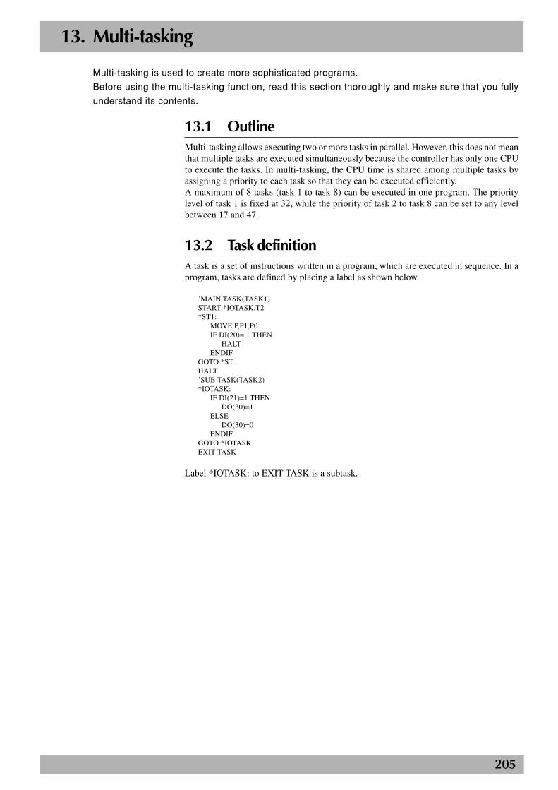
205
13. Multi-tasking
Multi-tasking is used to create more sophisticated programs.
Before using the multi-tasking function, read this section thoroughly and make sure that you fully
understand its contents.
13.1 OutlineMulti-tasking allows executing two or more tasks in parallel. However, this does not meanthat multiple tasks are executed simultaneously because the controller has only one CPUto execute the tasks. In multi-tasking, the CPU time is shared among multiple tasks byassigning a priority to each task so that they can be executed efficiently.A maximum of 8 tasks (task 1 to task 8) can be executed in one program. The prioritylevel of task 1 is fixed at 32, while the priority of task 2 to task 8 can be set to any levelbetween 17 and 47.
13.2 Task definitionA task is a set of instructions written in a program, which are executed in sequence. In aprogram, tasks are defined by placing a label as shown below.
’MAIN TASK(TASK1)START *IOTASK,T2*ST1:
MOVE P,P1,P0IF DI(20)= 1 THEN
HALTENDIF
GOTO *STHALT’SUB TASK(TASK2)*IOTASK:
IF DI(21)=1 THENDO(30)=1
ELSEDO(30)=0
ENDIFGOTO *IOTASKEXIT TASK
Label *IOTASK: to EXIT TASK is a subtask.
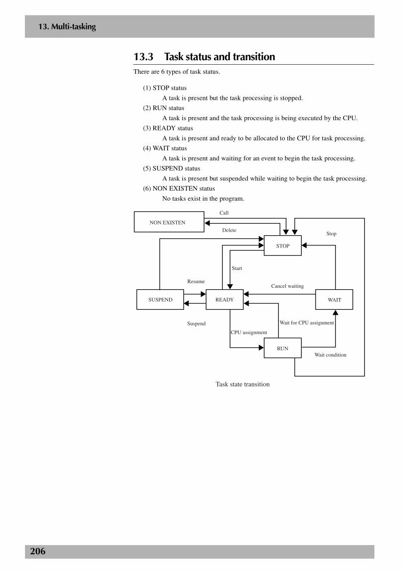
206
2
13. Multi-tasking
13.3 Task status and transitionThere are 6 types of task status.
(1) STOP status
A task is present but the task processing is stopped.
(2) RUN status
A task is present and the task processing is being executed by the CPU.
(3) READY status
A task is present and ready to be allocated to the CPU for task processing.
(4) WAIT status
A task is present and waiting for an event to begin the task processing.
(5) SUSPEND status
A task is present but suspended while waiting to begin the task processing.
(6) NON EXISTEN status
No tasks exist in the program.
Call
Delete
Resume
Start
Wait condition
Cancel waiting
Stop
Task state transition
STOP
RUN
NON EXISTEN
SUSPEND READY WAIT
CPU assignment
Wait for CPU assignmentSuspend
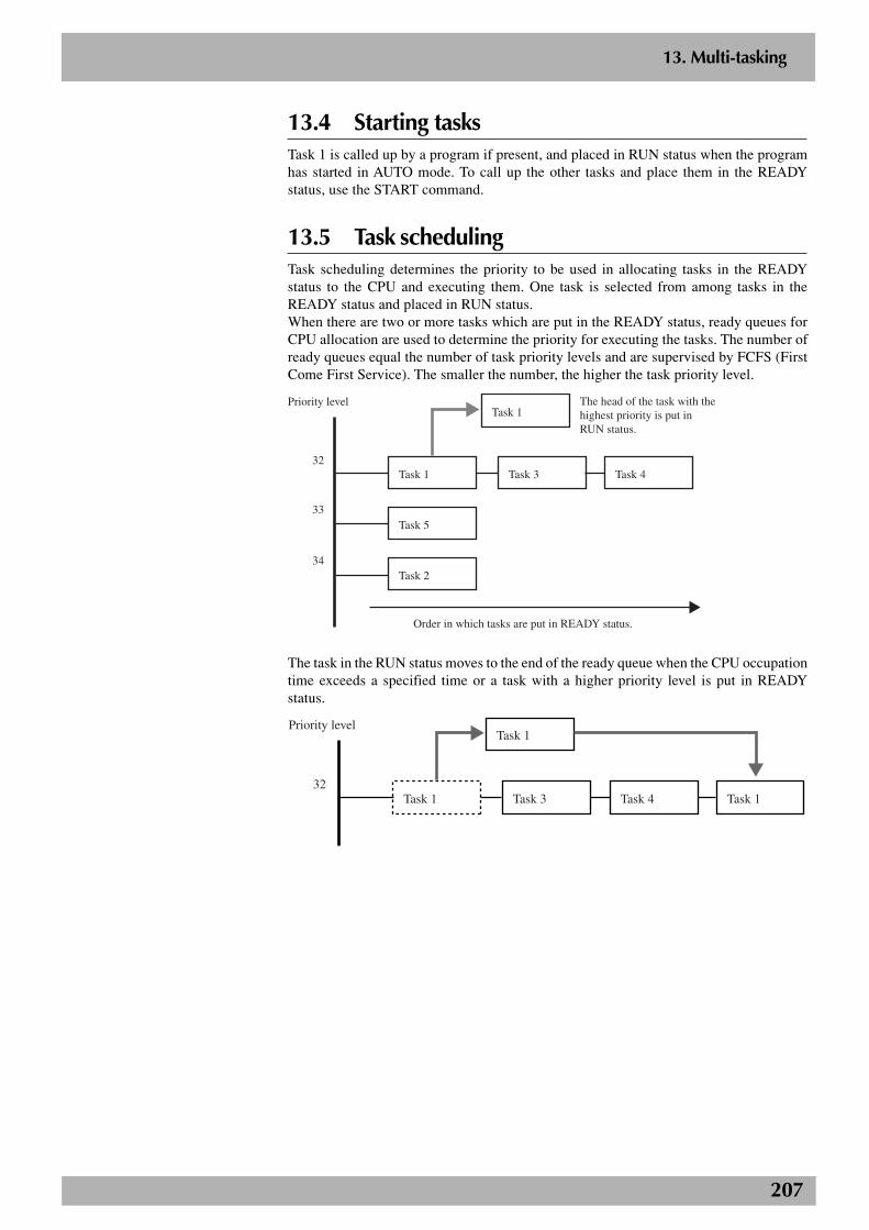
207
2
13. Multi-tasking
13.4 Starting tasksTask 1 is called up by a program if present, and placed in RUN status when the programhas started in AUTO mode. To call up the other tasks and place them in the READYstatus, use the START command.
13.5 Task schedulingTask scheduling determines the priority to be used in allocating tasks in the READYstatus to the CPU and executing them. One task is selected from among tasks in theREADY status and placed in RUN status.When there are two or more tasks which are put in the READY status, ready queues forCPU allocation are used to determine the priority for executing the tasks. The number ofready queues equal the number of task priority levels and are supervised by FCFS (FirstCome First Service). The smaller the number, the higher the task priority level.
Task 1 Task 3
Task 1
Task 4
Task 5
Task 2
Order in which tasks are put in READY status.
Priority level
32
33
34
The head of the task with the highest priority is put in RUN status.
The task in the RUN status moves to the end of the ready queue when the CPU occupationtime exceeds a specified time or a task with a higher priority level is put in READYstatus.
Task 1 Task 3
Task 1
Task 4 Task 1
Priority level
32
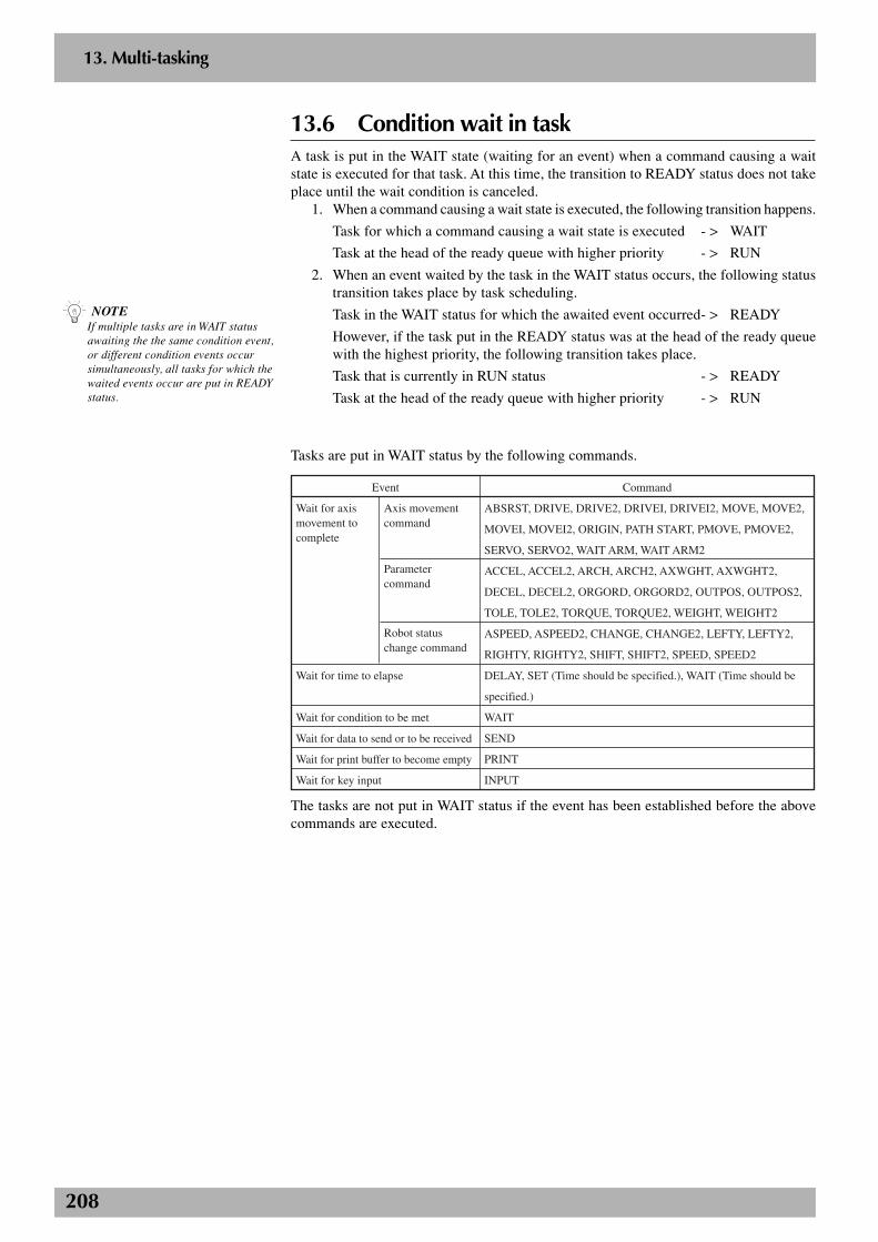
208
2
13. Multi-tasking
13.6 Condition wait in taskA task is put in the WAIT state (waiting for an event) when a command causing a waitstate is executed for that task. At this time, the transition to READY status does not takeplace until the wait condition is canceled.
1. When a command causing a wait state is executed, the following transition happens.
Task for which a command causing a wait state is executed - > WAIT
Task at the head of the ready queue with higher priority - > RUN
2. When an event waited by the task in the WAIT status occurs, the following statustransition takes place by task scheduling.
Task in the WAIT status for which the awaited event occurred- > READY
However, if the task put in the READY status was at the head of the ready queuewith the highest priority, the following transition takes place.
Task that is currently in RUN status - > READY
Task at the head of the ready queue with higher priority - > RUN
Tasks are put in WAIT status by the following commands.
Wait for axis movement to complete
Axis movement command
Parameter command
Robot status change command
ABSRST, DRIVE, DRIVE2, DRIVEI, DRIVEI2, MOVE, MOVE2,
MOVEI, MOVEI2, ORIGIN, PATH START, PMOVE, PMOVE2,
SERVO, SERVO2, WAIT ARM, WAIT ARM2
ACCEL, ACCEL2, ARCH, ARCH2, AXWGHT, AXWGHT2,
DECEL, DECEL2, ORGORD, ORGORD2, OUTPOS, OUTPOS2,
TOLE, TOLE2, TORQUE, TORQUE2, WEIGHT, WEIGHT2
ASPEED, ASPEED2, CHANGE, CHANGE2, LEFTY, LEFTY2,
RIGHTY, RIGHTY2, SHIFT, SHIFT2, SPEED, SPEED2
DELAY, SET (Time should be specified.), WAIT (Time should be
specified.)
WAIT
SEND
INPUT
Wait for time to elapse
Wait for condition to be met
Wait for data to send or to be received
Wait for print buffer to become empty
Wait for key input
Event Command
The tasks are not put in WAIT status if the event has been established before the abovecommands are executed.
n NOTEIf multiple tasks are in WAIT statusawaiting the the same condition event,or different condition events occursimultaneously, all tasks for which thewaited events occur are put in READYstatus.

209
2
13. Multi-tasking
13.7 Suspending and restarting tasksThe SUSPEND command temporarily stops tasks other than task 1 and places them inSUSPEND status. The SUSPEND command cannot be used for task 1.When the SUSPEND command is executed, the status transition takes place as follows.
Task that executed the SUSPEND command - > RUN
Specified task - > SUSPEND
Tasks in the SUSPEND status can be restarted with the RESTART command. However,the RESTART command cannot be used for task 1.When the RESTART command is executed, the status transition takes place as follows.
Task for which the RESTART command was executed - > RUN
Specified task - > READY
13.8 Deleting tasksTasks can delete themselves by using the EXIT TASK command and set to the NONEXISTEN (no task registration) status. The EXIT TASK command cannot be used fortask 1.When the EXIT TASK command is executed, the status transition takes place as follows.
Task that executed the EXIT TASK command - > NON EXISTEN
Task at the head of the ready queue with higher priority - > RUN
A task can also be deleted and put in the NON EXISTEN (no task registration) status bythe other tasks using the CUT command. The CUT command cannot be used for task 1.
When the CUT command is executed, the status transition takes place as follows.Task that executed the CUT command - > RUN
Specified task - > NON EXISTEN
n NOTEWhen the SUSPEND command isexecuted for a task that is in WAITstatus, the command being executedwith the specified task is terminated.
210
2
13. Multi-tasking
n NOTEWhen the program is restarted withoutbeing reset after the tasks have beenstopped by a cause other than (1), theneach task is processed from the statusin which the task stopped. This holdstrue when the power to the controlleris turned off and then turned on.
13.9 Stopping tasksAll tasks stop if any of the following cases occurs.
(1) HALT command is executed.
The program is reset and all tasks other than task 1 are put in the NON EXISTENstatus. Task 1 is put in the STOP status.
(2) HOLD command is executed.
All tasks are put in the STOP status. When the program is restarted, the tasks in theSTOP status set to the READY or SUSPEND status.
(3) STOP key on the programming box (MPB or RPB) is pressed or the interlocksignal is cut off.
Just as in the case where the HOLD command is executed, all tasks are put in theSTOP status. When the program is restarted, the tasks in the STOP status set to theREADY or SUSPEND status.
(4) When the emergency stop switch on the programming box (MPB or RPB) is pressedor the emergency stop signal is cut off.
All tasks are put in STOP status. At this point, the power to the robot is shut off andthe servo sets to the non-hold state. After the canceling emergency stop, when theprogram is restarted, the tasks in STOP status are set to the READY or SUSPENDstatus. To turn back on the power to the robot, other processing is required.
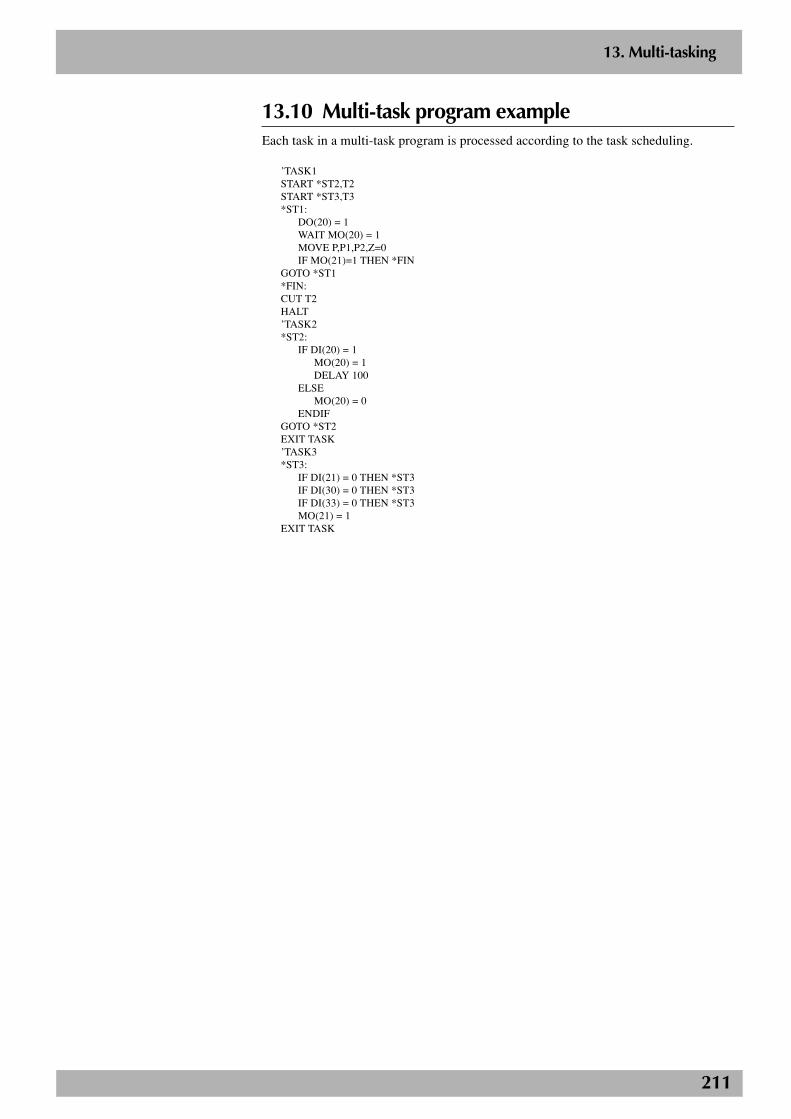
211
2
13. Multi-tasking
13.10 Multi-task program exampleEach task in a multi-task program is processed according to the task scheduling.
’TASK1START *ST2,T2START *ST3,T3*ST1:
DO(20) = 1WAIT MO(20) = 1MOVE P,P1,P2,Z=0IF MO(21)=1 THEN *FIN
GOTO *ST1*FIN:CUT T2HALT’TASK2*ST2:
IF DI(20) = 1MO(20) = 1DELAY 100
ELSEMO(20) = 0
ENDIFGOTO *ST2EXIT TASK’TASK3*ST3:
IF DI(21) = 0 THEN *ST3IF DI(30) = 0 THEN *ST3IF DI(33) = 0 THEN *ST3MO(21) = 1
EXIT TASK
212
2
13. Multi-tasking
c CAUTIONWhen the same variables and data areused in two or more tasks, usesufficient caution when rewriting thevariable and data. Improper changesmay cause trouble in the taskprocessing.
13.11 Sharing the dataPoint data, shift coordinate definition data, hand definition data, pallet definition data, allglobal variables and other variables are shared between all tasks.Execution of each task can be controlled while using the same variables and data sharedwith the other tasks. In this case, however, use sufficient caution when rewriting the variableand data because improper changes may cause trouble in the task processing.
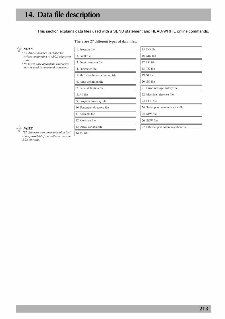
213
14. Data file description
There are 27 different types of data files.
1. Program file
2. Point file
3. Point comment file
4. Parameter file
5. Shift coordinate definition file
6. Hand definition file
7. Pallet definition file
8. All file
9. Program directory file
10. Parameter directory file
11. Variable file
12. Constant file
13. Array variable file
14. DI file
15. DO file
16. MO file
17. LO file
18. TO file
19. SI file
20. SO file
21. Error message history file
22. Machine reference file
23. EOF file
24. Serial port communication file
25. SIW file
26. SOW file
27. Ethernet port communication file
This section explains data files used with a SEND statement and READ/WRITE online commands.
n NOTE• All data is handled as character
strings conforming to ASCII charactercodes.
• No lower case alphabetic charactersmay be used in command statements.
n NOTE"27. Ethernet port communication file"is only available from software version8.22 onwards.
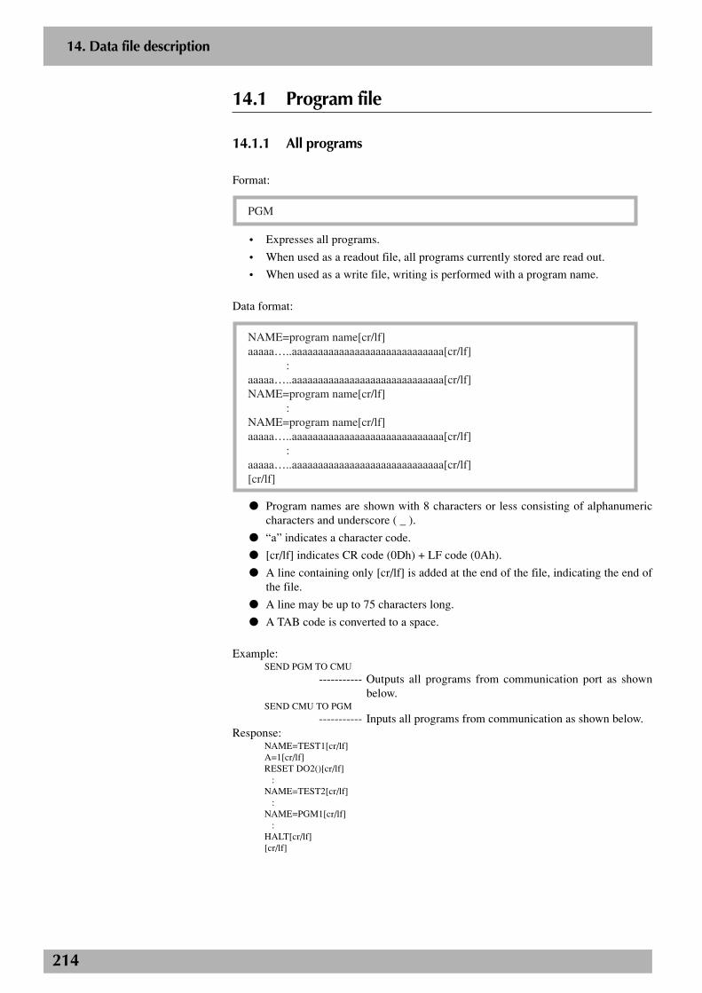
214
2
14. Data file description
14.1 Program file
14.1.1 All programs
Format:
PGM
• Expresses all programs.
• When used as a readout file, all programs currently stored are read out.
• When used as a write file, writing is performed with a program name.
Data format:
NAME=program name[cr/lf]aaaaa…..aaaaaaaaaaaaaaaaaaaaaaaaaaaaa[cr/lf] :aaaaa…..aaaaaaaaaaaaaaaaaaaaaaaaaaaaa[cr/lf]NAME=program name[cr/lf] :NAME=program name[cr/lf]aaaaa…..aaaaaaaaaaaaaaaaaaaaaaaaaaaaa[cr/lf] :aaaaa…..aaaaaaaaaaaaaaaaaaaaaaaaaaaaa[cr/lf][cr/lf]
● Program names are shown with 8 characters or less consisting of alphanumericcharacters and underscore ( _ ).
● “a” indicates a character code.
● [cr/lf] indicates CR code (0Dh) + LF code (0Ah).
● A line containing only [cr/lf] is added at the end of the file, indicating the end ofthe file.
● A line may be up to 75 characters long.
● A TAB code is converted to a space.
Example:SEND PGM TO CMU
----------- Outputs all programs from communication port as shownbelow.
SEND CMU TO PGM
----------- Inputs all programs from communication as shown below.Response:
NAME=TEST1[cr/lf]A=1[cr/lf]RESET DO2()[cr/lf] :NAME=TEST2[cr/lf] :NAME=PGM1[cr/lf] :HALT[cr/lf][cr/lf]
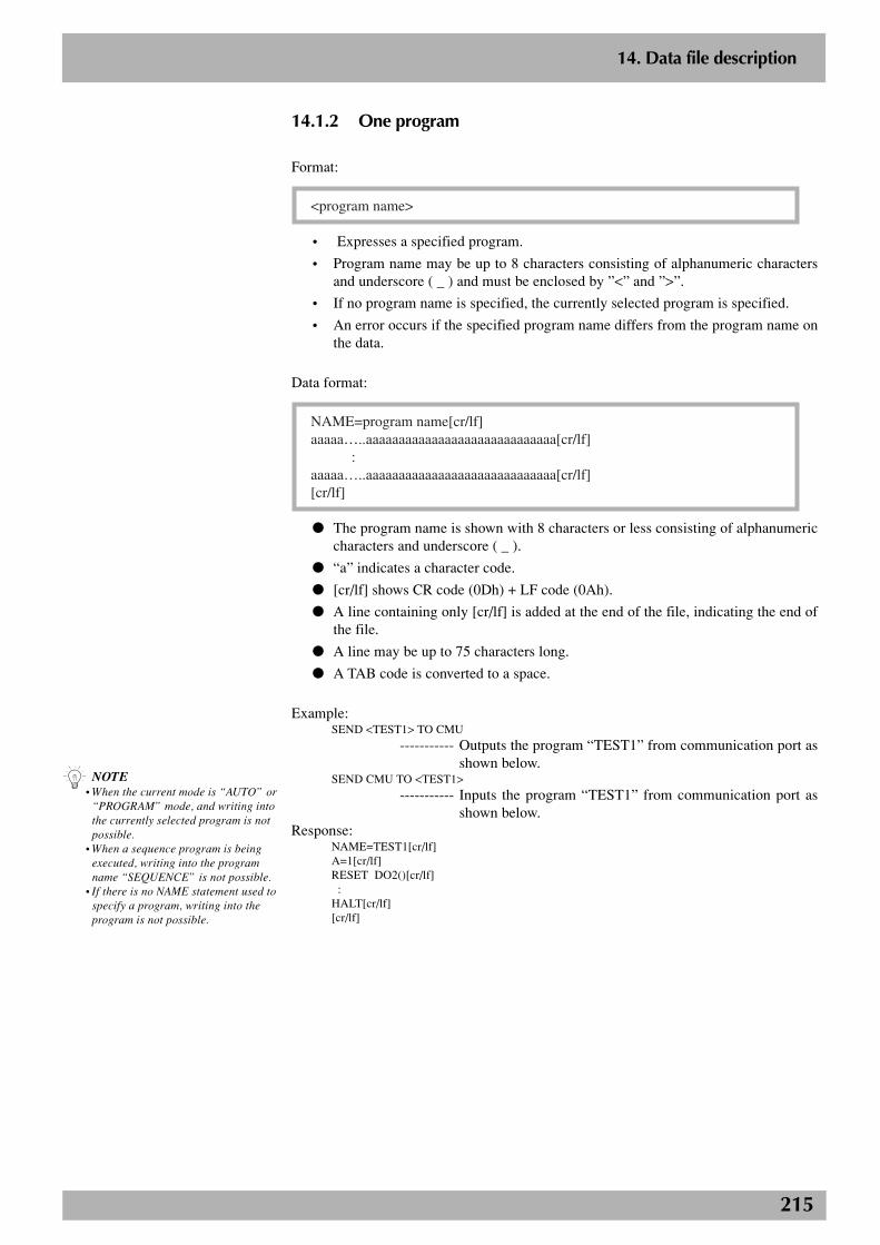
215
2
14. Data file description
14.1.2 One program
Format:
<program name>
• Expresses a specified program.
• Program name may be up to 8 characters consisting of alphanumeric charactersand underscore ( _ ) and must be enclosed by ”<” and ”>”.
• If no program name is specified, the currently selected program is specified.
• An error occurs if the specified program name differs from the program name onthe data.
Data format:
NAME=program name[cr/lf]aaaaa…..aaaaaaaaaaaaaaaaaaaaaaaaaaaaa[cr/lf] :aaaaa…..aaaaaaaaaaaaaaaaaaaaaaaaaaaaa[cr/lf][cr/lf]
● The program name is shown with 8 characters or less consisting of alphanumericcharacters and underscore ( _ ).
● “a” indicates a character code.
● [cr/lf] shows CR code (0Dh) + LF code (0Ah).
● A line containing only [cr/lf] is added at the end of the file, indicating the end ofthe file.
● A line may be up to 75 characters long.
● A TAB code is converted to a space.
Example:SEND <TEST1> TO CMU
----------- Outputs the program “TEST1” from communication port asshown below.
SEND CMU TO <TEST1>
----------- Inputs the program “TEST1” from communication port asshown below.
Response:NAME=TEST1[cr/lf]A=1[cr/lf]RESET DO2()[cr/lf] :HALT[cr/lf][cr/lf]
n NOTE• When the current mode is “AUTO” or
“PROGRAM” mode, and writing intothe currently selected program is notpossible.
• When a sequence program is beingexecuted, writing into the programname “SEQUENCE” is not possible.
• If there is no NAME statement used tospecify a program, writing into theprogram is not possible.
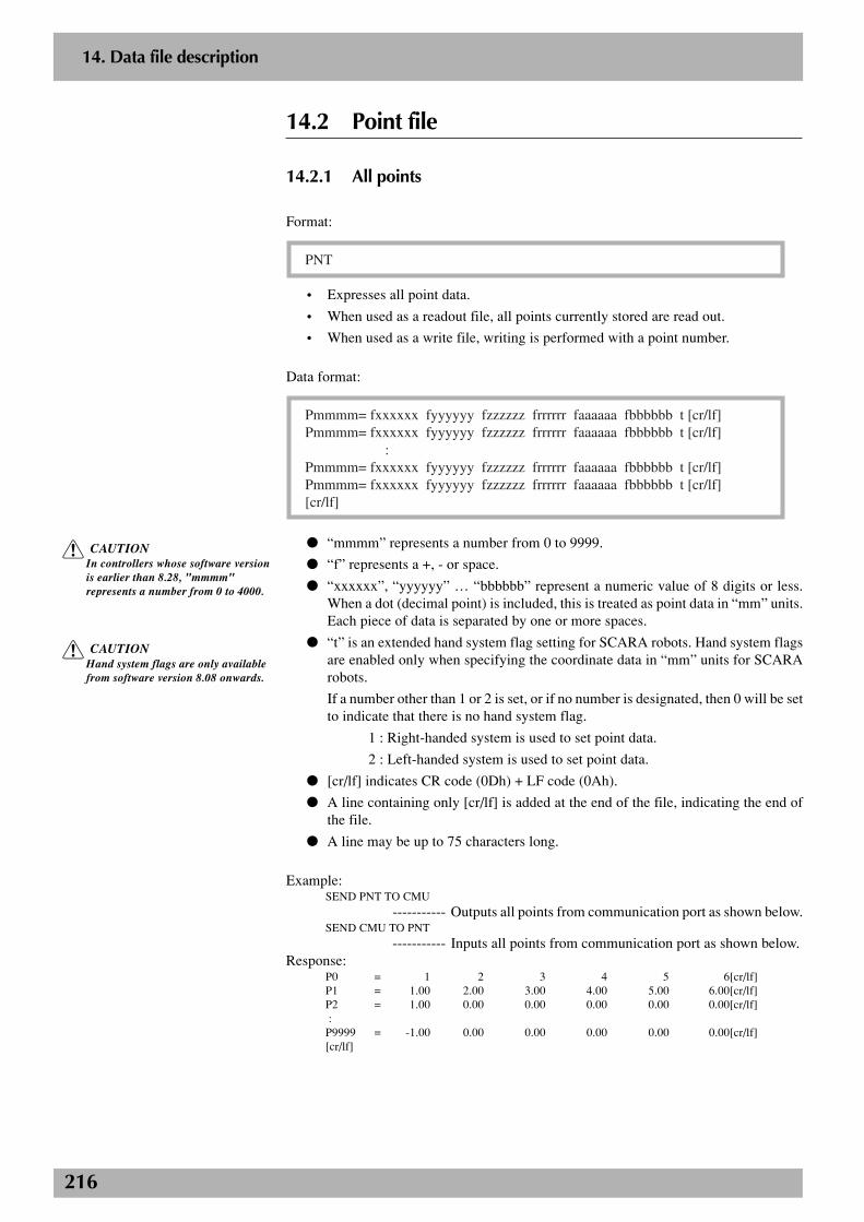
216
2
14. Data file description
14.2 Point file
14.2.1 All points
Format:
PNT
• Expresses all point data.
• When used as a readout file, all points currently stored are read out.
• When used as a write file, writing is performed with a point number.
Data format:
Pmmmm= fxxxxxx fyyyyyy fzzzzzz frrrrrr faaaaaa fbbbbbb t [cr/lf]Pmmmm= fxxxxxx fyyyyyy fzzzzzz frrrrrr faaaaaa fbbbbbb t [cr/lf] :Pmmmm= fxxxxxx fyyyyyy fzzzzzz frrrrrr faaaaaa fbbbbbb t [cr/lf]Pmmmm= fxxxxxx fyyyyyy fzzzzzz frrrrrr faaaaaa fbbbbbb t [cr/lf][cr/lf]
● “mmmm” represents a number from 0 to 9999.
● “f” represents a +, - or space.
● “xxxxxx”, “yyyyyy” … “bbbbbb” represent a numeric value of 8 digits or less.When a dot (decimal point) is included, this is treated as point data in “mm” units.Each piece of data is separated by one or more spaces.
● “t” is an extended hand system flag setting for SCARA robots. Hand system flagsare enabled only when specifying the coordinate data in “mm” units for SCARArobots.
If a number other than 1 or 2 is set, or if no number is designated, then 0 will be setto indicate that there is no hand system flag.
1 : Right-handed system is used to set point data.
2 : Left-handed system is used to set point data.
● [cr/lf] indicates CR code (0Dh) + LF code (0Ah).
● A line containing only [cr/lf] is added at the end of the file, indicating the end ofthe file.
● A line may be up to 75 characters long.
Example:SEND PNT TO CMU
----------- Outputs all points from communication port as shown below.SEND CMU TO PNT
----------- Inputs all points from communication port as shown below.Response:
P0 = 1 2 3 4 5 6[cr/lf]P1 = 1.00 2.00 3.00 4.00 5.00 6.00[cr/lf]P2 = 1.00 0.00 0.00 0.00 0.00 0.00[cr/lf] :P9999 = -1.00 0.00 0.00 0.00 0.00 0.00[cr/lf][cr/lf]
c CAUTIONIn controllers whose software versionis earlier than 8.28, "mmmm"represents a number from 0 to 4000.
c CAUTIONHand system flags are only availablefrom software version 8.08 onwards.
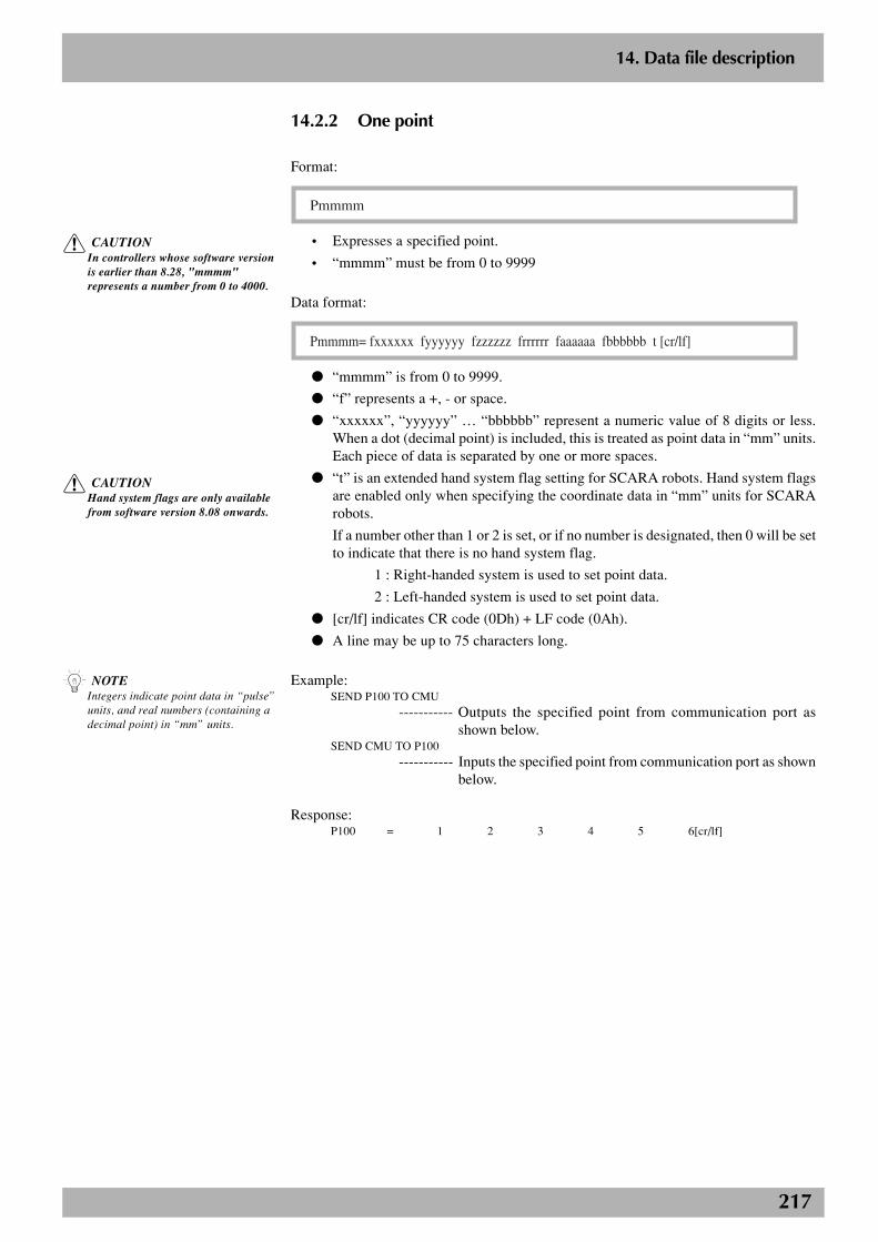
217
2
14. Data file description
14.2.2 One point
Format:
Pmmmm
• Expresses a specified point.
• “mmmm” must be from 0 to 9999
Data format:
Pmmmm= fxxxxxx fyyyyyy fzzzzzz frrrrrr faaaaaa fbbbbbb t [cr/lf]
● “mmmm” is from 0 to 9999.
● “f” represents a +, - or space.
● “xxxxxx”, “yyyyyy” … “bbbbbb” represent a numeric value of 8 digits or less.When a dot (decimal point) is included, this is treated as point data in “mm” units.Each piece of data is separated by one or more spaces.
● “t” is an extended hand system flag setting for SCARA robots. Hand system flagsare enabled only when specifying the coordinate data in “mm” units for SCARArobots.
If a number other than 1 or 2 is set, or if no number is designated, then 0 will be setto indicate that there is no hand system flag.
1 : Right-handed system is used to set point data.
2 : Left-handed system is used to set point data.
● [cr/lf] indicates CR code (0Dh) + LF code (0Ah).
● A line may be up to 75 characters long.
Example:SEND P100 TO CMU
----------- Outputs the specified point from communication port asshown below.
SEND CMU TO P100
----------- Inputs the specified point from communication port as shownbelow.
Response:P100 = 1 2 3 4 5 6[cr/lf]
n NOTEIntegers indicate point data in “pulse”units, and real numbers (containing adecimal point) in “mm” units.
c CAUTIONIn controllers whose software versionis earlier than 8.28, "mmmm"represents a number from 0 to 4000.
c CAUTIONHand system flags are only availablefrom software version 8.08 onwards.
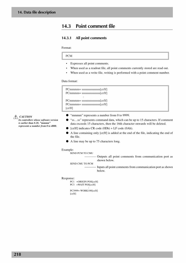
218
2
14. Data file description
14.3 Point comment file
14.3.1 All point comments
Format:
PCM
• Expresses all point comments.
• When used as a readout file, all point comments currently stored are read out.
• When used as a write file, writing is performed with a point comment number.
Data format:
PCmmmm= sssssssssssssss[cr/lf]PCmmmm= sssssssssssssss[cr/lf] :PCmmmm= sssssssssssssss[cr/lf]PCmmmm= sssssssssssssss[cr/lf][cr/lf]
● “mmmm” represents a number from 0 to 9999.
● “ss…ss” represents command data, which can be up to 15 characters. If commentdata exceeds 15 characters, then the 16th character onwards will be deleted.
● [cr/lf] indicates CR code (0Dh) + LF code (0Ah).
● A line containing only [cr/lf] is added at the end of the file, indicating the end ofthe file.
● A line may be up to 75 characters long.
Example:SEND PCM TO CMU
----------- Outputs all point comments from communication port asshown below.
SEND CMU TO PCM
----------- Inputs all point comments from communication port as shownbelow.
Response:PC1 =ORIGIN POS[cr/lf]PC3 =WAIT POS[cr/lf]
:PC3999= WORK100[cr/lf][cr/lf]
c CAUTIONIn controllers whose software versionis earlier than 8.28, "mmmm"represents a number from 0 to 4000.
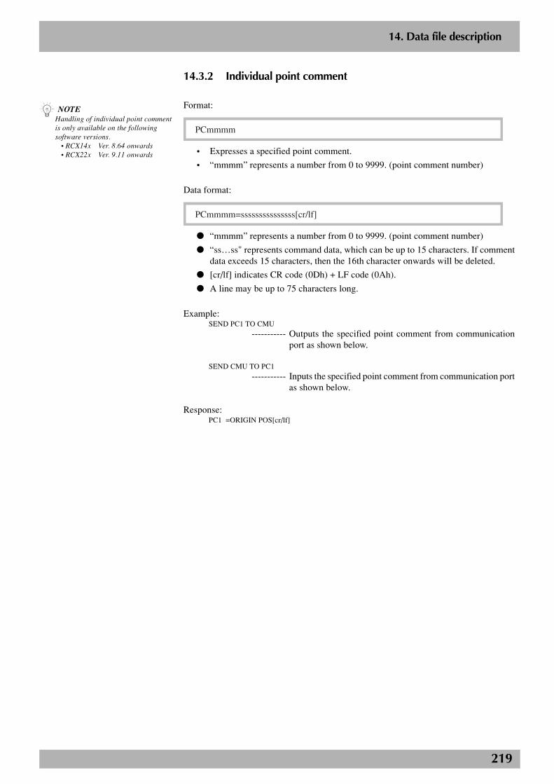
219
2
14. Data file description
14.3.2 Individual point comment
Format:
PCmmmm
• Expresses a specified point comment.
• “mmmm” represents a number from 0 to 9999. (point comment number)
Data format:
PCmmmm=sssssssssssssss[cr/lf]
● “mmmm” represents a number from 0 to 9999. (point comment number)
● “ss…ss" represents command data, which can be up to 15 characters. If commentdata exceeds 15 characters, then the 16th character onwards will be deleted.
● [cr/lf] indicates CR code (0Dh) + LF code (0Ah).
● A line may be up to 75 characters long.
Example:SEND PC1 TO CMU
----------- Outputs the specified point comment from communicationport as shown below.
SEND CMU TO PC1
----------- Inputs the specified point comment from communication portas shown below.
Response:PC1 =ORIGIN POS[cr/lf]
n NOTEHandling of individual point commentis only available on the followingsoftware versions. • RCX14x Ver. 8.64 onwards • RCX22x Ver. 9.11 onwards
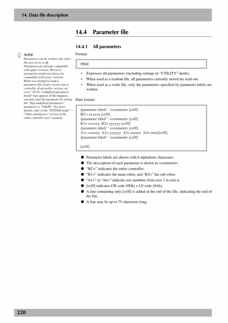
220
2
14. Data file description
14.4 Parameter file
14.4.1 All parameters
Format:
PRM
• Expresses all parameters (including settings in “UTILITY” mode).
• When used as a readout file, all parameters currently stored are read out.
• When used as a write file, only the parameters specified by parameter labels arewritten.
Data format:
/parameter label/ ’ <comment> [cr/lf]RC= xxxxxx [cr/lf]/parameter label/ ’ <comment> [cr/lf]R1= xxxxxx R2= yyyyyy [cr/lf]/parameter label/ ’ <comment> [cr/lf]A1= xxxxxx A2= yyyyyy A3= zzzzzz A4= rrrrrr[cr/lf]/parameter label/ ’ <comment> [cr/lf] :[cr/lf]
● Parameter labels are shown with 6 alphabetic characters.
● The description of each parameter is shown in <comment>.
● “RC=” indicates the entire controller.
● “R1=” indicates the main robot, and “R2=” the sub robot.
● “A1=” to “An=” indicate axis numbers from axis 1 to axis n.
● [cr/lf] indicates CR code (0Dh) + LF code (0Ah).
● A line containing only [cr/lf] is added at the end of the file, indicating the end ofthe file.
● A line may be up to 75 characters long.
n NOTE· Parameters can be written only when
the axis servo is off.· Parameters are already compatible
with upper versions. However,parameters might not always becompatible with lower versions.
· When you attempt to load aparameter file of new version into acontroller of an earlier version, anerror "10.14 : Undefined parameterfound" may appear. If this happens,you may load the parameter by settingthe "Skip undefined parameters"parameter to "VALID". For moredetails, refer to the "SYSTEM mode" –"Other parameters" section in therobot controller user's manual.

221
2
14. Data file description
Example:SEND PRM TO CMU
----------- Outputs all parameters from communication port as shownbelow.
SEND CMU TO PRM
----------- Inputs all parameters from communication port as shownbelow.
Response:/RBTNUM/ ’Robot number(V8.01/R1001)[cr/lf] R1= 3000 R2= 3010[cr/lf]/AXES / ’Number of axes[cr/lf] R1= 2 R2= 2[cr/lf]/AXSNUM/ ’Axis number(V1.01/V1.01/V1.01/V1.01/-----/-----/-----/-----/)[cr/lf] A1= 5000 A2= 5001 A3= 5010 A4= 5011[cr/lf] A5= 0 A6= 0 A7= 0 A8= 0[cr/lf]/ATTRIB/ ’Axis attribute[cr/lf] A1= 33792 A2= 33792 A3= 33792 A4= 33792[cr/lf] A5= 256 A6= 256 A7= 256 A8= 256[cr/lf]/WEIGHT/ ’Tip weight[kg][cr/lf] R1= 2 R2= 12[cr/lf]
:/CURPNO/ ’Port number of output[cr/lf] RC= 20[cr/lf]/CURPT1/ ’Compare point number1[cr/lf] RC= 0[cr/lf]/CURPT2/ ’Compare point number2[cr/lf] RC= 0[cr/lf][cr/lf]
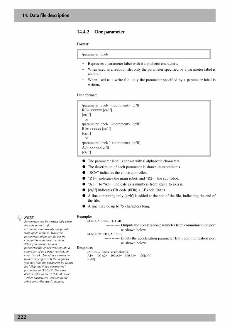
222
2
14. Data file description
14.4.2 One parameter
Format:
/parameter label/
• Expresses a parameter label with 6 alphabetic characters.
• When used as a readout file, only the parameter specified by a parameter label isread out.
• When used as a write file, only the parameter specified by a parameter label iswritten.
Data format:
/parameter label/ ’ <comment> [cr/lf]RC= xxxxxx [cr/lf][cr/lf] or/parameter label/ ’ <comment> [cr/lf]R?= xxxxxx [cr/lf][cr/lf] or/parameter label/ ’ <comment> [cr/lf]A?= xxxxxx[cr/lf][cr/lf]
● The parameter label is shown with 6 alphabetic characters.
● The description of each parameter is shown in <comment>.
● “RC=” indicates the entire controller.
● “R1=” indicates the main robot, and “R2=” the sub robot.
● “A1=” to “An=” indicate axis numbers from axis 1 to axis n.
● [cr/lf] indicates CR code (0Dh) + LF code (0Ah).
● A line containing only [cr/lf] is added at the end of the file, indicating the end ofthe file.
● A line may be up to 75 characters long.
Example:SEND /ACCEL / TO CMU
----------- Outputs the acceleration parameter from communication portas shown below.
SEND CMU TO /ACCEL /----- ------ Inputs the acceleration parameter from communication port
as shown below.Response:
/ACCEL / ’Accel coefficient[%]A1= 100 A2= 100 A3= 100 A4= 100[cr/lf][cr/lf]
n NOTE· Parameters can be written only when
the axis servo is off.· Parameters are already compatible
with upper versions. However,parameters might not always becompatible with lower versions.
· When you attempt to load aparameter file of new version into acontroller of an earlier version, anerror "10.14 : Undefined parameterfound" may appear. If this happens,you may load the parameter by settingthe "Skip undefined parameters"parameter to "VALID". For moredetails, refer to the "SYSTEM mode" –"Other parameters" section in therobot controller user's manual.
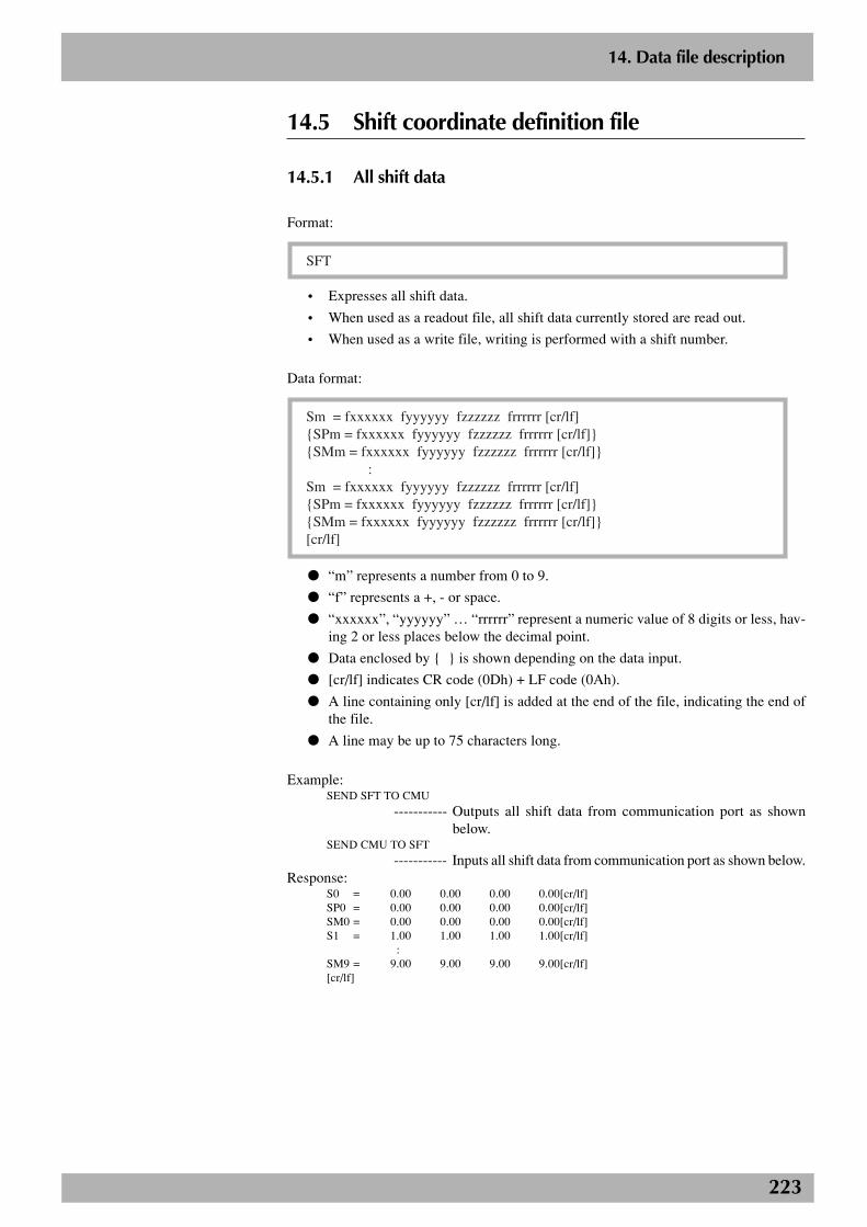
223
2
14. Data file description
14.5 Shift coordinate definition file
14.5.1 All shift data
Format:
SFT
• Expresses all shift data.
• When used as a readout file, all shift data currently stored are read out.
• When used as a write file, writing is performed with a shift number.
Data format:
Sm = fxxxxxx fyyyyyy fzzzzzz frrrrrr [cr/lf]{SPm = fxxxxxx fyyyyyy fzzzzzz frrrrrr [cr/lf]}{SMm = fxxxxxx fyyyyyy fzzzzzz frrrrrr [cr/lf]} :Sm = fxxxxxx fyyyyyy fzzzzzz frrrrrr [cr/lf]{SPm = fxxxxxx fyyyyyy fzzzzzz frrrrrr [cr/lf]}{SMm = fxxxxxx fyyyyyy fzzzzzz frrrrrr [cr/lf]}[cr/lf]
● “m” represents a number from 0 to 9.
● “f” represents a +, - or space.
● “xxxxxx”, “yyyyyy” … “rrrrrr” represent a numeric value of 8 digits or less, hav-ing 2 or less places below the decimal point.
● Data enclosed by { } is shown depending on the data input.
● [cr/lf] indicates CR code (0Dh) + LF code (0Ah).
● A line containing only [cr/lf] is added at the end of the file, indicating the end ofthe file.
● A line may be up to 75 characters long.
Example:SEND SFT TO CMU
----------- Outputs all shift data from communication port as shownbelow.
SEND CMU TO SFT
----------- Inputs all shift data from communication port as shown below.Response:
S0 = 0.00 0.00 0.00 0.00[cr/lf]SP0 = 0.00 0.00 0.00 0.00[cr/lf]SM0 = 0.00 0.00 0.00 0.00[cr/lf]S1 = 1.00 1.00 1.00 1.00[cr/lf]
:SM9 = 9.00 9.00 9.00 9.00[cr/lf][cr/lf]
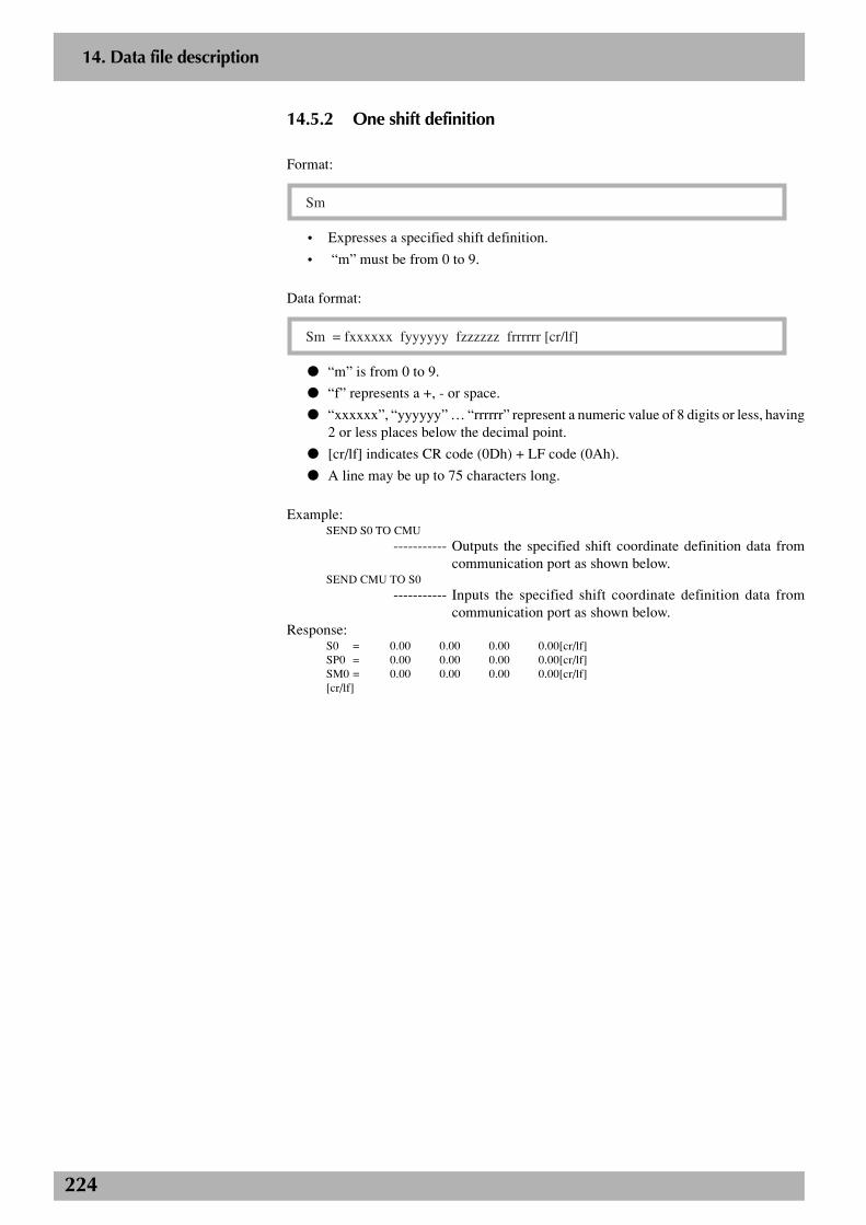
224
2
14. Data file description
14.5.2 One shift definition
Format:
Sm
• Expresses a specified shift definition.
• “m” must be from 0 to 9.
Data format:
Sm = fxxxxxx fyyyyyy fzzzzzz frrrrrr [cr/lf]
● “m” is from 0 to 9.
● “f” represents a +, - or space.
● “xxxxxx”, “yyyyyy” … “rrrrrr” represent a numeric value of 8 digits or less, having2 or less places below the decimal point.
● [cr/lf] indicates CR code (0Dh) + LF code (0Ah).
● A line may be up to 75 characters long.
Example:SEND S0 TO CMU
----------- Outputs the specified shift coordinate definition data fromcommunication port as shown below.
SEND CMU TO S0----------- Inputs the specified shift coordinate definition data from
communication port as shown below.Response:
S0 = 0.00 0.00 0.00 0.00[cr/lf]SP0 = 0.00 0.00 0.00 0.00[cr/lf]SM0 = 0.00 0.00 0.00 0.00[cr/lf][cr/lf]
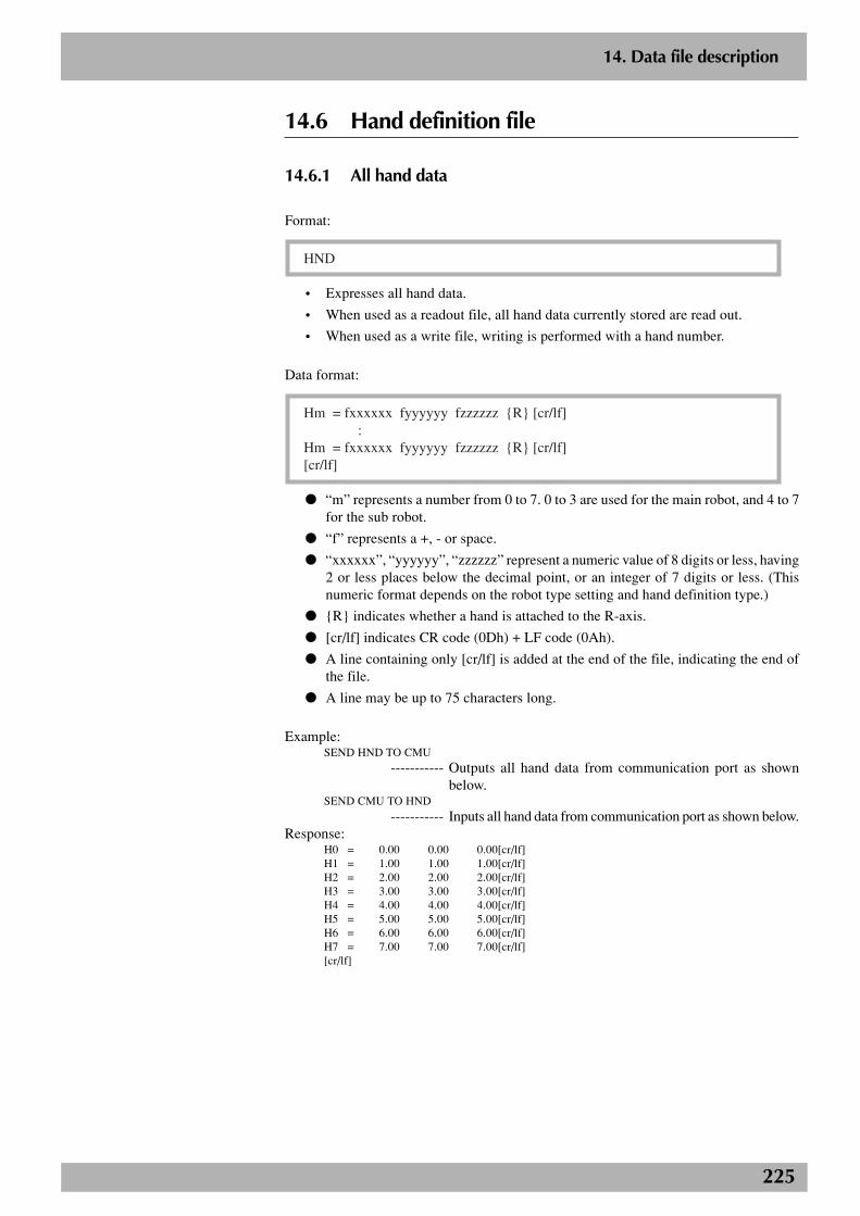
225
2
14. Data file description
14.6 Hand definition file
14.6.1 All hand data
Format:
HND
• Expresses all hand data.
• When used as a readout file, all hand data currently stored are read out.
• When used as a write file, writing is performed with a hand number.
Data format:
Hm = fxxxxxx fyyyyyy fzzzzzz {R} [cr/lf] :Hm = fxxxxxx fyyyyyy fzzzzzz {R} [cr/lf][cr/lf]
● “m” represents a number from 0 to 7. 0 to 3 are used for the main robot, and 4 to 7for the sub robot.
● “f” represents a +, - or space.
● “xxxxxx”, “yyyyyy”, “zzzzzz” represent a numeric value of 8 digits or less, having2 or less places below the decimal point, or an integer of 7 digits or less. (Thisnumeric format depends on the robot type setting and hand definition type.)
● {R} indicates whether a hand is attached to the R-axis.
● [cr/lf] indicates CR code (0Dh) + LF code (0Ah).
● A line containing only [cr/lf] is added at the end of the file, indicating the end ofthe file.
● A line may be up to 75 characters long.
Example:SEND HND TO CMU
----------- Outputs all hand data from communication port as shownbelow.
SEND CMU TO HND----------- Inputs all hand data from communication port as shown below.
Response:H0 = 0.00 0.00 0.00[cr/lf]H1 = 1.00 1.00 1.00[cr/lf]H2 = 2.00 2.00 2.00[cr/lf]H3 = 3.00 3.00 3.00[cr/lf]H4 = 4.00 4.00 4.00[cr/lf]H5 = 5.00 5.00 5.00[cr/lf]H6 = 6.00 6.00 6.00[cr/lf]H7 = 7.00 7.00 7.00[cr/lf][cr/lf]
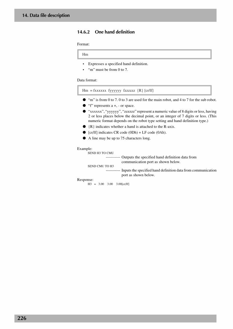
226
2
14. Data file description
14.6.2 One hand definition
Format:
Hm
• Expresses a specified hand definition.
• “m” must be from 0 to 7.
Data format:
Hm = fxxxxxx fyyyyyy fzzzzzz {R} [cr/lf]
● “m” is from 0 to 7. 0 to 3 are used for the main robot, and 4 to 7 for the sub robot.
● “f” represents a +, - or space.
● “xxxxxx”, “yyyyyy”, “zzzzzz” represent a numeric value of 8 digits or less, having2 or less places below the decimal point, or an integer of 7 digits or less. (Thisnumeric format depends on the robot type setting and hand definition type.)
● {R} indicates whether a hand is attached to the R-axis.
● [cr/lf] indicates CR code (0Dh) + LF code (0Ah).
● A line may be up to 75 characters long.
Example:SEND H3 TO CMU
----------- Outputs the specified hand definition data fromcommunication port as shown below.
SEND CMU TO H3
----------- Inputs the specified hand definition data from communicationport as shown below.
Response:H3 = 3.00 3.00 3.00[cr/lf]
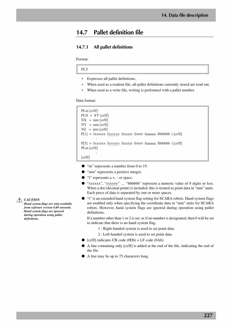
227
2
14. Data file description
14.7 Pallet definition file
14.7.1 All pallet definitions
Format:
PLT
• Expresses all pallet definitions.
• When used as a readout file, all pallet definitions currently stored are read out.
• When used as a write file, writing is performed with a pallet number.
Data format:
PLm [cr/lf]PLN = XY [cr/lf]NX = nnn [cr/lf]NY = nnn [cr/lf]NZ = nnn [cr/lf]P[1] = fxxxxxx fyyyyyy fzzzzzz frrrrrr faaaaaa fbbbbbb t [cr/lf] :P[5] = fxxxxxx fyyyyyy fzzzzzz frrrrrr faaaaaa fbbbbbb t [cr/lf]PLm [cr/lf] :[cr/lf]
● “m” represents a number from 0 to 19.
● “nnn” represents a positive integer.
● “f” represents a +, - or space.
● “xxxxxx”, “yyyyyy” … “bbbbbb” represent a numeric value of 8 digits or less.When a dot (decimal point) is included, this is treated as point data in “mm” units.Each piece of data is separated by one or more spaces.
● “t” is an extended hand system flag setting for SCARA robots. Hand system flagsare enabled only when specifying the coordinate data in “mm” units for SCARArobots. However, hand system flags are ignored during operation using palletdefinitions.
If a number other than 1 or 2 is set, or if no number is designated, then 0 will be setto indicate that there is no hand system flag.
1 : Right-handed system is used to set point data.
2 : Left-handed system is used to set point data.
● [cr/lf] indicates CR code (0Dh) + LF code (0Ah).
● A line containing only [cr/lf] is added at the end of the file, indicating the end ofthe file.
● A line may be up to 75 characters long.
c CAUTION· Hand system flags are only available
from software version 8.08 onwards.· Hand system flags are ignored
during operation using palletdefinitions.
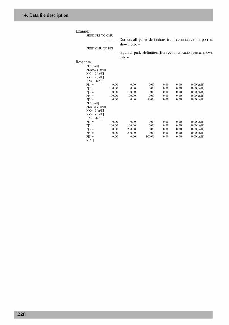
228
2
14. Data file description
Example:SEND PLT TO CMU
----------- Outputs all pallet definitions from communication port asshown below.
SEND CMU TO PLT
----------- Inputs all pallet definitions from communication port as shownbelow.
Response:PL0[cr/lf]PLN=XY[cr/lf]NX= 3[cr/lf]NY= 4[cr/lf]NZ= 2[cr/lf]P[1]= 0.00 0.00 0.00 0.00 0.00 0.00[cr/lf]P[2]= 100.00 0.00 0.00 0.00 0.00 0.00[cr/lf]P[3]= 0.00 100.00 0.00 0.00 0.00 0.00[cr/lf]P[4]= 100.00 100.00 0.00 0.00 0.00 0.00[cr/lf]P[5]= 0.00 0.00 50.00 0.00 0.00 0.00[cr/lf]PL1[cr/lf]PLN=XY[cr/lf]NX= 3[cr/lf]NY= 4[cr/lf]NZ= 2[cr/lf]P[1]= 0.00 0.00 0.00 0.00 0.00 0.00[cr/lf]P[2]= 100.00 100.00 0.00 0.00 0.00 0.00[cr/lf]P[3]= 0.00 200.00 0.00 0.00 0.00 0.00[cr/lf]P[4]= 100.00 200.00 0.00 0.00 0.00 0.00[cr/lf]P[5]= 0.00 0.00 100.00 0.00 0.00 0.00[cr/lf][cr/lf]
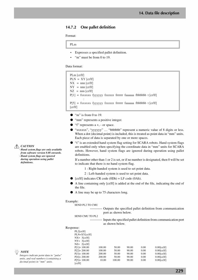
229
2
14. Data file description
14.7.2 One pallet definition
Format:
PLm
• Expresses a specified pallet definition.
• “m” must be from 0 to 19.
Data format:
PLm [cr/lf]PLN = XY [cr/lf]NX = nnn [cr/lf]NY = nnn [cr/lf]NZ = nnn [cr/lf]P[1] = fxxxxxx fyyyyyy fzzzzzz frrrrrr faaaaaa fbbbbbb t [cr/lf] :P[5] = fxxxxxx fyyyyyy fzzzzzz frrrrrr faaaaaa fbbbbbb t [cr/lf][cr/lf]
● “m” is from 0 to 19.
● “nnn” represents a positive integer.
● “f” represents a +, - or space.
● “xxxxxx”, “yyyyyy” … “bbbbbb” represent a numeric value of 8 digits or less.When a dot (decimal point) is included, this is treated as point data in “mm” units.Each piece of data is separated by one or more spaces.
● “t” is an extended hand system flag setting for SCARA robots. Hand system flagsare enabled only when specifying the coordinate data in “mm” units for SCARArobots. However, hand system flags are ignored during operation using palletdefinitions.
If a number other than 1 or 2 is set, or if no number is designated, then 0 will be setto indicate that there is no hand system flag.
1 : Right-handed system is used to set point data.
2 : Left-handed system is used to set point data.
● [cr/lf] indicates CR code (0Dh) + LF code (0Ah).
● A line containing only [cr/lf] is added at the end of the file, indicating the end ofthe file.
● A line may be up to 75 characters long.
Example:SEND PL2 TO CMU
----------- Outputs the specified pallet definition from communicationport as shown below.
SEND CMU TO PL2
----------- Inputs the specified pallet definition from communication portas shown below.
Response:PL2[cr/lf]PLN=XY[cr/lf]NX= 3[cr/lf]NY= 3[cr/lf]NZ= 2[cr/lf]P[1]= 100.00 100.00 50.00 90.00 0.00 0.00[cr/lf]P[2]= 200.00 100.00 50.00 90.00 0.00 0.00[cr/lf]P[3]= 100.00 200.00 50.00 90.00 0.00 0.00[cr/lf]P[4]= 200.00 200.00 50.00 90.00 0.00 0.00[cr/lf]P[5]= 100.00 10.00 100.00 90.00 0.00 0.00[cr/lf][cr/lf]
n NOTEIntegers indicate point data in “pulse”units, and real numbers (containing adecimal point) in “mm” units.
c CAUTION· Hand system flags are only available
from software version 8.08 onwards.· Hand system flags are ignored
during operation using palletdefinitions.
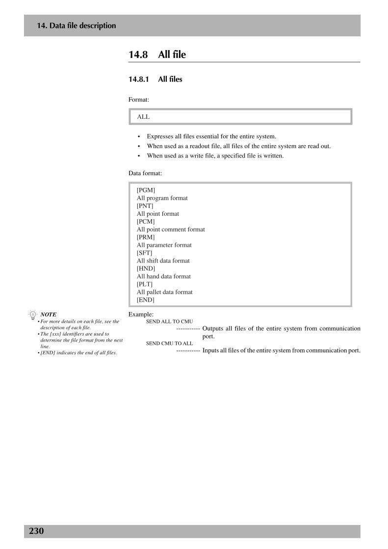
230
2
14. Data file description
14.8 All file
14.8.1 All files
Format:
ALL
• Expresses all files essential for the entire system.
• When used as a readout file, all files of the entire system are read out.
• When used as a write file, a specified file is written.
Data format:
[PGM]All program format[PNT]All point format[PCM]All point comment format[PRM]All parameter format[SFT]All shift data format[HND]All hand data format[PLT]All pallet data format[END]
Example:SEND ALL TO CMU
----------- Outputs all files of the entire system from communicationport.
SEND CMU TO ALL
----------- Inputs all files of the entire system from communication port.
n NOTE• For more details on each file, see the
description of each file.• The [xxx] identifiers are used to
determine the file format from the nextline.
• [END] indicates the end of all files.
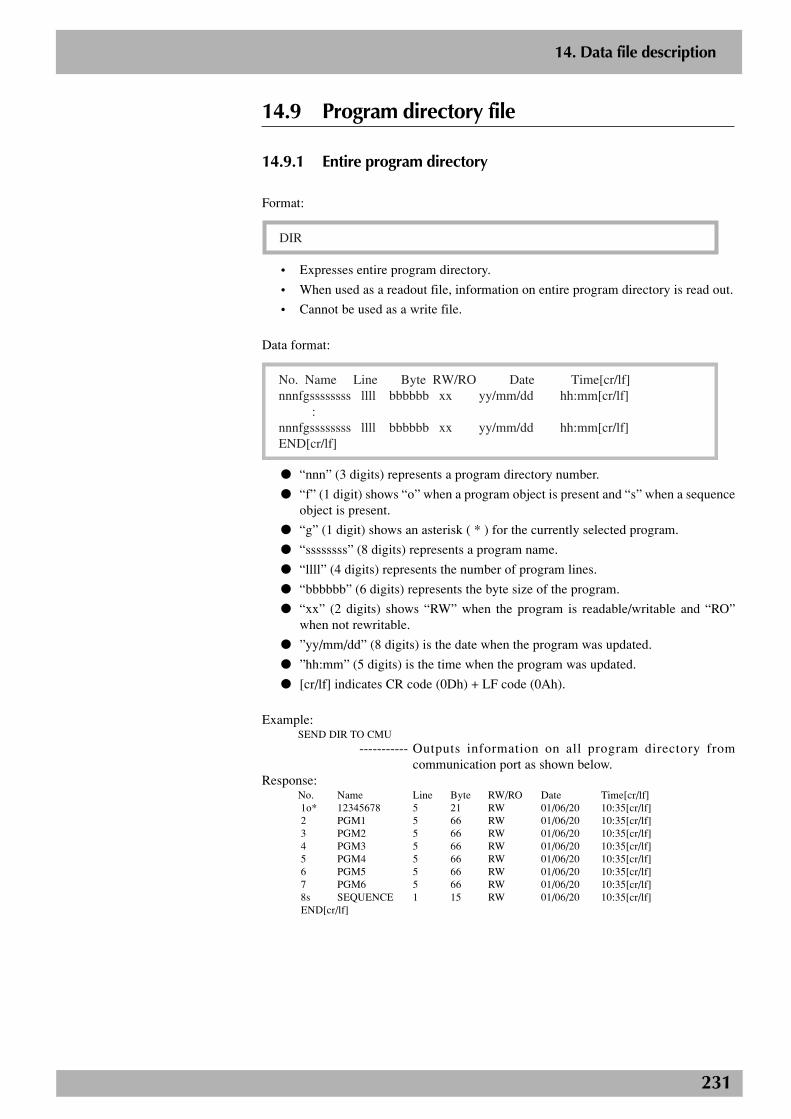
231
2
14. Data file description
14.9 Program directory file
14.9.1 Entire program directory
Format:
DIR
• Expresses entire program directory.
• When used as a readout file, information on entire program directory is read out.
• Cannot be used as a write file.
Data format:
No. Name Line Byte RW/RO Date Time[cr/lf]nnnfgssssssss llll bbbbbb xx yy/mm/dd hh:mm[cr/lf] :nnnfgssssssss llll bbbbbb xx yy/mm/dd hh:mm[cr/lf]END[cr/lf]
● “nnn” (3 digits) represents a program directory number.
● “f” (1 digit) shows “o” when a program object is present and “s” when a sequenceobject is present.
● “g” (1 digit) shows an asterisk ( * ) for the currently selected program.
● “ssssssss” (8 digits) represents a program name.
● “llll” (4 digits) represents the number of program lines.
● “bbbbbb” (6 digits) represents the byte size of the program.
● “xx” (2 digits) shows “RW” when the program is readable/writable and “RO”when not rewritable.
● ”yy/mm/dd” (8 digits) is the date when the program was updated.
● ”hh:mm” (5 digits) is the time when the program was updated.
● [cr/lf] indicates CR code (0Dh) + LF code (0Ah).
Example:SEND DIR TO CMU
----------- Outputs information on all program directory fromcommunication port as shown below.
Response:No. Name Line Byte RW/RO Date Time[cr/lf] 1o* 12345678 5 21 RW 01/06/20 10:35[cr/lf] 2 PGM1 5 66 RW 01/06/20 10:35[cr/lf] 3 PGM2 5 66 RW 01/06/20 10:35[cr/lf] 4 PGM3 5 66 RW 01/06/20 10:35[cr/lf] 5 PGM4 5 66 RW 01/06/20 10:35[cr/lf] 6 PGM5 5 66 RW 01/06/20 10:35[cr/lf] 7 PGM6 5 66 RW 01/06/20 10:35[cr/lf] 8s SEQUENCE 1 15 RW 01/06/20 10:35[cr/lf] END[cr/lf]
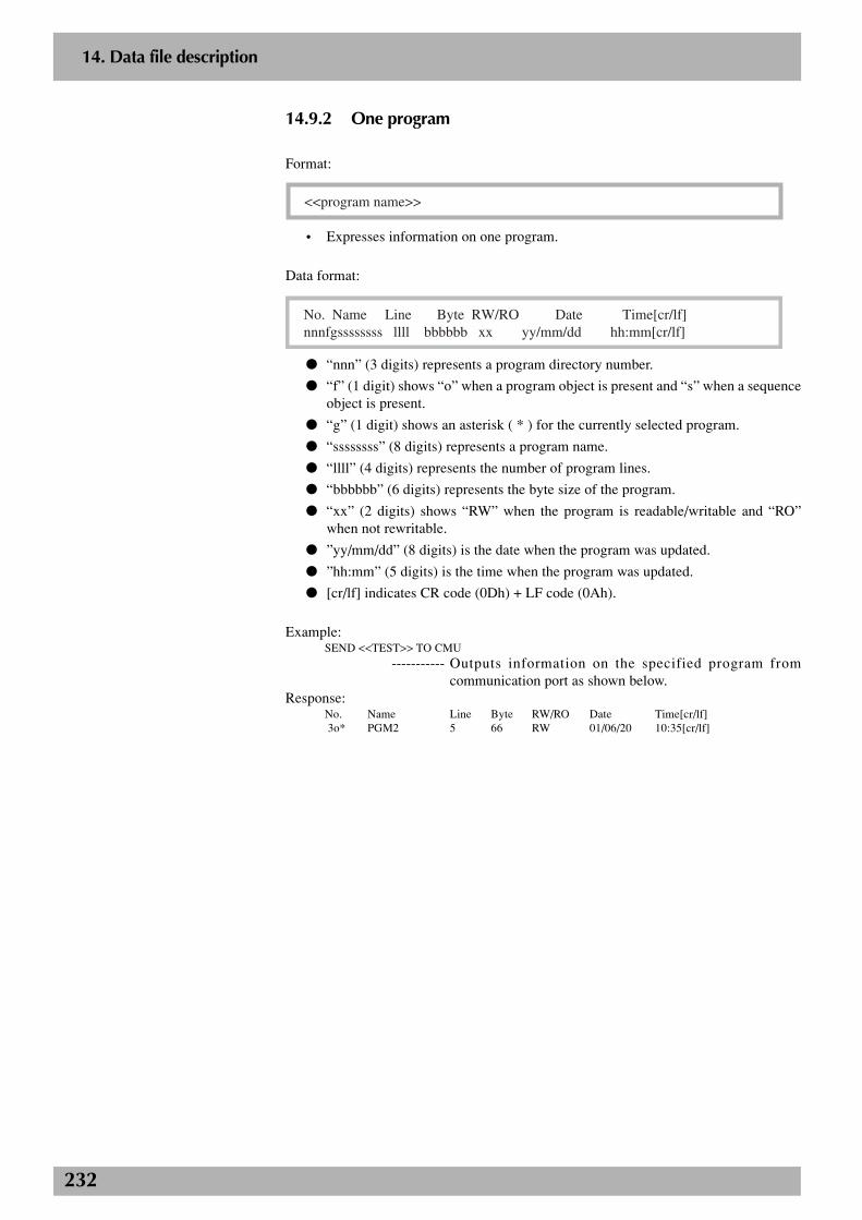
232
2
14. Data file description
14.9.2 One program
Format:
<<program name>>
• Expresses information on one program.
Data format:
No. Name Line Byte RW/RO Date Time[cr/lf]nnnfgssssssss llll bbbbbb xx yy/mm/dd hh:mm[cr/lf]
● “nnn” (3 digits) represents a program directory number.
● “f” (1 digit) shows “o” when a program object is present and “s” when a sequenceobject is present.
● “g” (1 digit) shows an asterisk ( * ) for the currently selected program.
● “ssssssss” (8 digits) represents a program name.
● “llll” (4 digits) represents the number of program lines.
● “bbbbbb” (6 digits) represents the byte size of the program.
● “xx” (2 digits) shows “RW” when the program is readable/writable and “RO”when not rewritable.
● ”yy/mm/dd” (8 digits) is the date when the program was updated.
● ”hh:mm” (5 digits) is the time when the program was updated.
● [cr/lf] indicates CR code (0Dh) + LF code (0Ah).
Example:SEND <<TEST>> TO CMU
----------- Outputs information on the specified program fromcommunication port as shown below.
Response:No. Name Line Byte RW/RO Date Time[cr/lf] 3o* PGM2 5 66 RW 01/06/20 10:35[cr/lf]
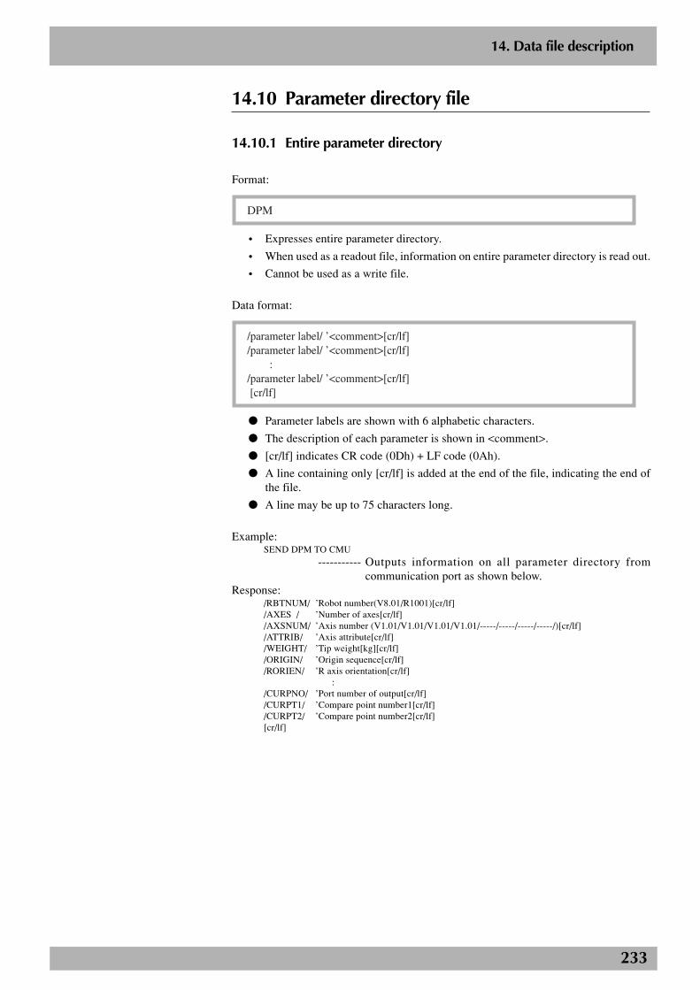
233
2
14. Data file description
14.10 Parameter directory file
14.10.1 Entire parameter directory
Format:
DPM
• Expresses entire parameter directory.
• When used as a readout file, information on entire parameter directory is read out.
• Cannot be used as a write file.
Data format:
/parameter label/ ’<comment>[cr/lf]/parameter label/ ’<comment>[cr/lf] :/parameter label/ ’<comment>[cr/lf] [cr/lf]
● Parameter labels are shown with 6 alphabetic characters.
● The description of each parameter is shown in <comment>.
● [cr/lf] indicates CR code (0Dh) + LF code (0Ah).
● A line containing only [cr/lf] is added at the end of the file, indicating the end ofthe file.
● A line may be up to 75 characters long.
Example:SEND DPM TO CMU
----------- Outputs information on all parameter directory fromcommunication port as shown below.
Response:/RBTNUM/ ’Robot number(V8.01/R1001)[cr/lf]/AXES / ’Number of axes[cr/lf]/AXSNUM/ ’Axis number (V1.01/V1.01/V1.01/V1.01/-----/-----/-----/-----/)[cr/lf]/ATTRIB/ ’Axis attribute[cr/lf]/WEIGHT/ ’Tip weight[kg][cr/lf]/ORIGIN/ ’Origin sequence[cr/lf]/RORIEN/ ’R axis orientation[cr/lf]
:/CURPNO/ ’Port number of output[cr/lf]/CURPT1/ ’Compare point number1[cr/lf]/CURPT2/ ’Compare point number2[cr/lf][cr/lf]
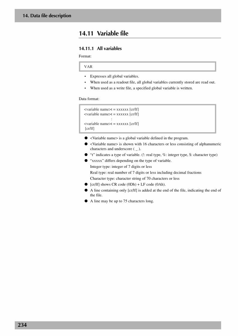
234
2
14. Data file description
14.11 Variable file
14.11.1 All variables
Format:
VAR
• Expresses all global variables.
• When used as a readout file, all global variables currently stored are read out.
• When used as a write file, a specified global variable is written.
Data format:
<variable name>t = xxxxxx [cr/lf]<variable name>t = xxxxxx [cr/lf] :<variable name>t = xxxxxx [cr/lf] [cr/lf]
● <Variable name> is a global variable defined in the program.
● <Variable name> is shown with 16 characters or less consisting of alphanumericcharacters and underscore ( _ ).
● “t” indicates a type of variable. (!: real type, %: integer type, $: character type)
● “xxxxx” differs depending on the type of variable.
Integer type: integer of 7 digits or less
Real type: real number of 7 digits or less including decimal fractions
Character type: character string of 70 characters or less
● [cr/lf] shows CR code (0Dh) + LF code (0Ah).
● A line containing only [cr/lf] is added at the end of the file, indicating the end ofthe file.
● A line may be up to 75 characters long.
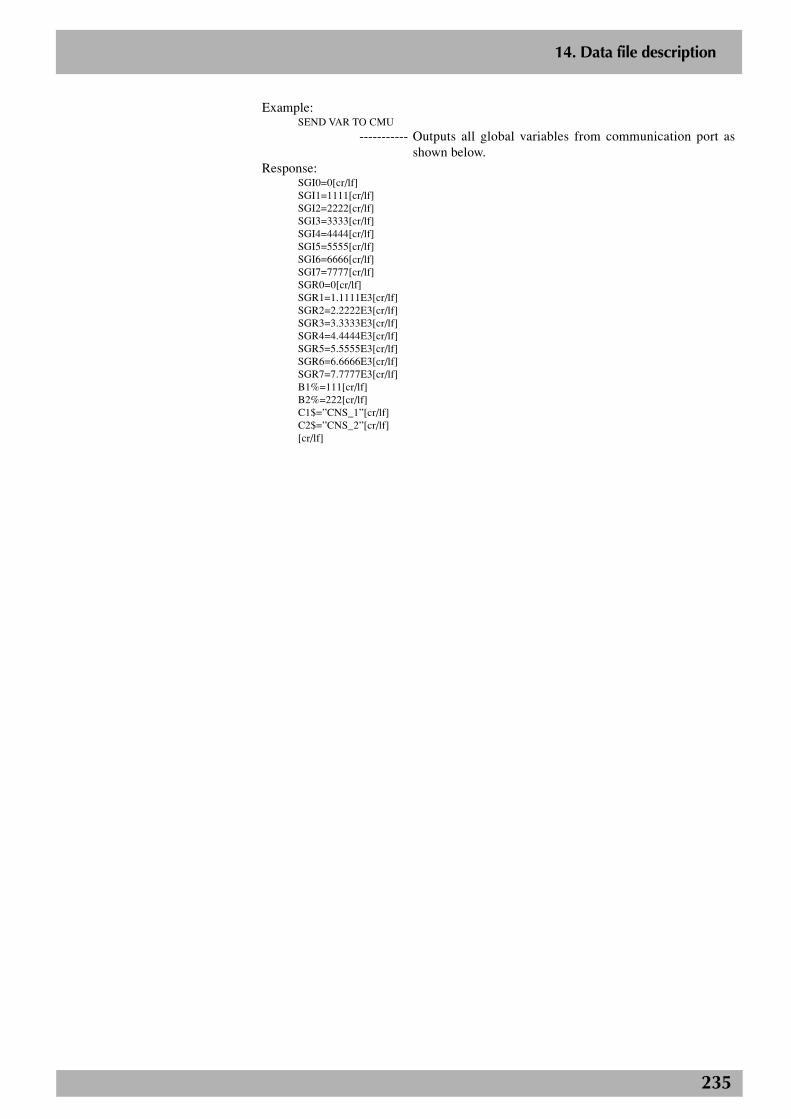
235
2
14. Data file description
Example:SEND VAR TO CMU
----------- Outputs all global variables from communication port asshown below.
Response:SGI0=0[cr/lf]SGI1=1111[cr/lf]SGI2=2222[cr/lf]SGI3=3333[cr/lf]SGI4=4444[cr/lf]SGI5=5555[cr/lf]SGI6=6666[cr/lf]SGI7=7777[cr/lf]SGR0=0[cr/lf]SGR1=1.1111E3[cr/lf]SGR2=2.2222E3[cr/lf]SGR3=3.3333E3[cr/lf]SGR4=4.4444E3[cr/lf]SGR5=5.5555E3[cr/lf]SGR6=6.6666E3[cr/lf]SGR7=7.7777E3[cr/lf]B1%=111[cr/lf]B2%=222[cr/lf]C1$=”CNS_1”[cr/lf]C2$=”CNS_2”[cr/lf][cr/lf]
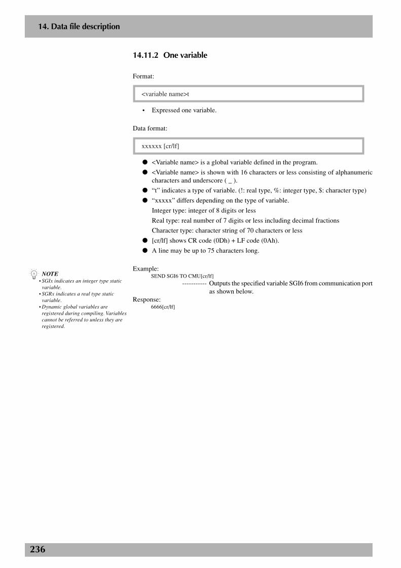
236
2
14. Data file description
14.11.2 One variable
Format:
<variable name>t
• Expressed one variable.
Data format:
xxxxxx [cr/lf]
● <Variable name> is a global variable defined in the program.
● <Variable name> is shown with 16 characters or less consisting of alphanumericcharacters and underscore ( _ ).
● “t” indicates a type of variable. (!: real type, %: integer type, $: character type)
● “xxxxx” differs depending on the type of variable.
Integer type: integer of 8 digits or less
Real type: real number of 7 digits or less including decimal fractions
Character type: character string of 70 characters or less
● [cr/lf] shows CR code (0Dh) + LF code (0Ah).
● A line may be up to 75 characters long.
Example:SEND SGI6 TO CMU[cr/lf]
----------- Outputs the specified variable SGI6 from communication portas shown below.
Response:6666[cr/lf]
n NOTE• SGIx indicates an integer type static
variable.• SGRx indicates a real type static
variable.• Dynamic global variables are
registered during compiling. Variablescannot be referred to unless they areregistered.
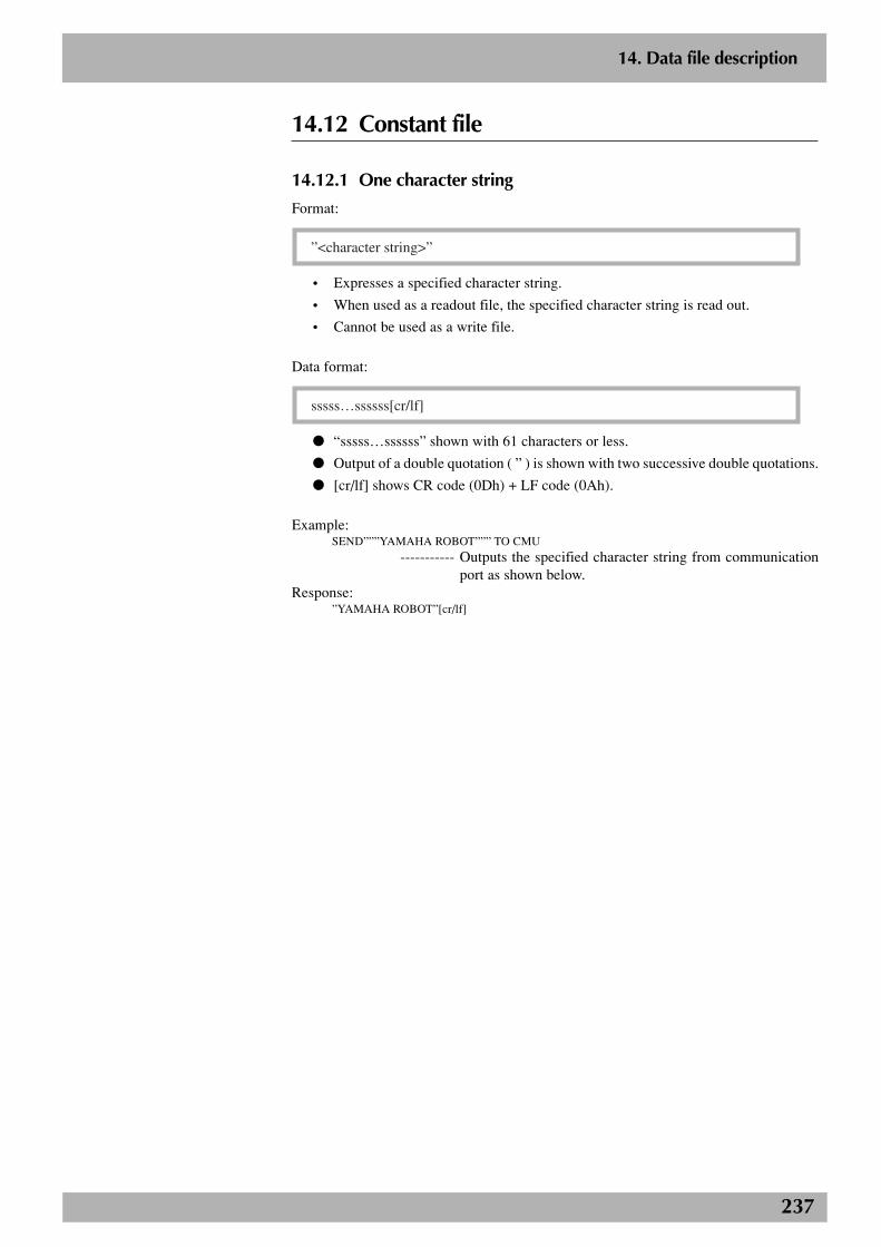
237
2
14. Data file description
14.12 Constant file
14.12.1 One character string
Format:
”<character string>”
• Expresses a specified character string.
• When used as a readout file, the specified character string is read out.
• Cannot be used as a write file.
Data format:
sssss…ssssss[cr/lf]
● “sssss…ssssss” shown with 61 characters or less.
● Output of a double quotation ( ” ) is shown with two successive double quotations.
● [cr/lf] shows CR code (0Dh) + LF code (0Ah).
Example:SEND”””YAMAHA ROBOT””” TO CMU
----------- Outputs the specified character string from communicationport as shown below.
Response:”YAMAHA ROBOT”[cr/lf]
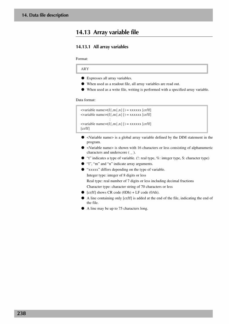
238
2
14. Data file description
14.13 Array variable file
14.13.1 All array variables
Format:
ARY
● Expresses all array variables.
● When used as a readout file, all array variables are read out.
● When used as a write file, writing is performed with a specified array variable.
Data format:
<variable name>t(l{,m{,n}}) = xxxxxx [cr/lf]<variable name>t(l{,m{,n}}) = xxxxxx [cr/lf] :<variable name>t(l{,m{,n}}) = xxxxxx [cr/lf][cr/lf]
● <Variable name> is a global array variable defined by the DIM statement in theprogram.
● <Variable name> is shown with 16 characters or less consisting of alphanumericcharacters and underscore ( _ ).
● “t” indicates a type of variable. (!: real type, %: integer type, $: character type)
● “l”, “m” and “n” indicate array arguments.
● “xxxxx” differs depending on the type of variable.
Integer type: integer of 8 digits or less
Real type: real number of 7 digits or less including decimal fractions
Character type: character string of 70 characters or less
● [cr/lf] shows CR code (0Dh) + LF code (0Ah).
● A line containing only [cr/lf] is added at the end of the file, indicating the end ofthe file.
● A line may be up to 75 characters long.
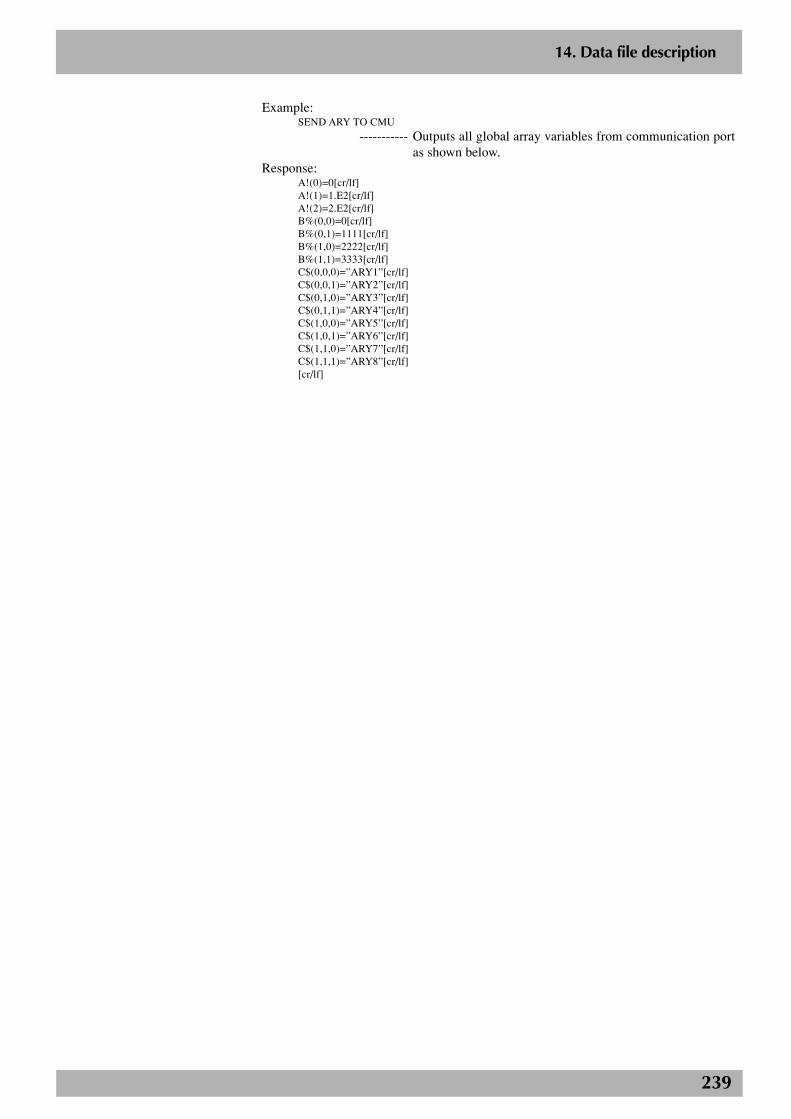
239
2
14. Data file description
Example:SEND ARY TO CMU
----------- Outputs all global array variables from communication portas shown below.
Response:A!(0)=0[cr/lf]A!(1)=1.E2[cr/lf]A!(2)=2.E2[cr/lf]B%(0,0)=0[cr/lf]B%(0,1)=1111[cr/lf]B%(1,0)=2222[cr/lf]B%(1,1)=3333[cr/lf]C$(0,0,0)=”ARY1”[cr/lf]C$(0,0,1)=”ARY2”[cr/lf]C$(0,1,0)=”ARY3”[cr/lf]C$(0,1,1)=”ARY4”[cr/lf]C$(1,0,0)=”ARY5”[cr/lf]C$(1,0,1)=”ARY6”[cr/lf]C$(1,1,0)=”ARY7”[cr/lf]C$(1,1,1)=”ARY8”[cr/lf][cr/lf]

240
2
14. Data file description
14.13.2 One array variable
Format:
<variable name>t(l{,m{,n}})
• Expresses one array variable.
Data format:
xxxxxx [cr/lf]
● <Variable name> is a global array variable defined by the DIM statement in theprogram.
● <Variable name> is shown with 16 characters or less consisting of alphanumericcharacters and underscore ( _ ).
● “t” indicates a type of variable. (!: real type, %: integer type, $: character type)
● “l”, “m” and “n” indicate array arguments.
● “xxxxx” differs depending on the type of variable.
Integer type: integer of 8 digits or less
Real type: real number of 7 digits or less including decimal fractions
Character type: character string of 70 characters or less
● [cr/lf] shows CR code (0Dh) + LF code (0Ah).
Example:SEND CMU TO C1$(2)[cr/lf]
----------- Inputs the specified array variable C1$(2) fromcommunication port as shown below.
Response:YAMAHA ROBOT[cr/lf]
n NOTEArray variables defined by the DIMstatement are registered duringcompiling. Array variables cannot bereferred to unless they are registered.
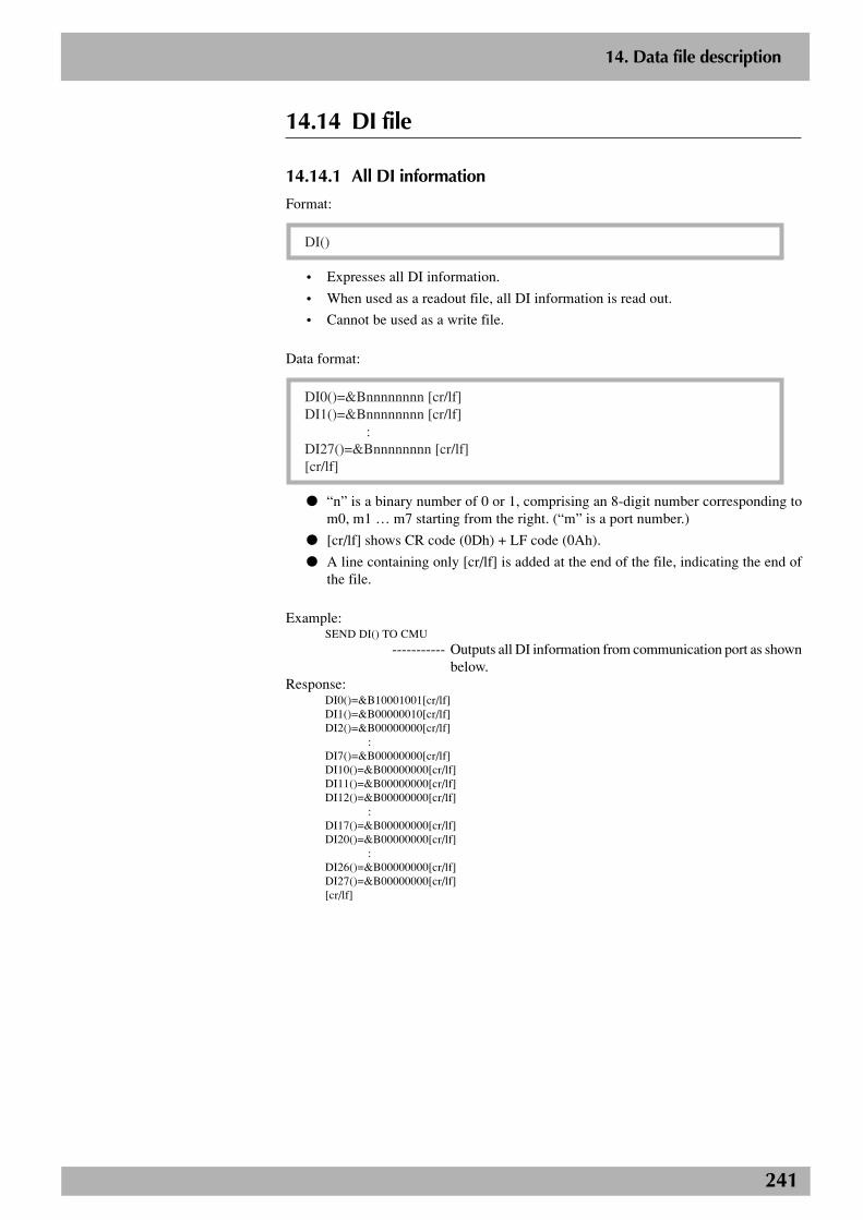
241
2
14. Data file description
14.14 DI file
14.14.1 All DI information
Format:
DI()
• Expresses all DI information.
• When used as a readout file, all DI information is read out.
• Cannot be used as a write file.
Data format:
DI0()=&Bnnnnnnnn [cr/lf]DI1()=&Bnnnnnnnn [cr/lf] :DI27()=&Bnnnnnnnn [cr/lf][cr/lf]
● “n” is a binary number of 0 or 1, comprising an 8-digit number corresponding tom0, m1 … m7 starting from the right. (“m” is a port number.)
● [cr/lf] shows CR code (0Dh) + LF code (0Ah).
● A line containing only [cr/lf] is added at the end of the file, indicating the end ofthe file.
Example:SEND DI() TO CMU
----------- Outputs all DI information from communication port as shownbelow.
Response:DI0()=&B10001001[cr/lf]DI1()=&B00000010[cr/lf]DI2()=&B00000000[cr/lf]
:DI7()=&B00000000[cr/lf]DI10()=&B00000000[cr/lf]DI11()=&B00000000[cr/lf]DI12()=&B00000000[cr/lf]
:DI17()=&B00000000[cr/lf]DI20()=&B00000000[cr/lf]
:DI26()=&B00000000[cr/lf]DI27()=&B00000000[cr/lf][cr/lf]
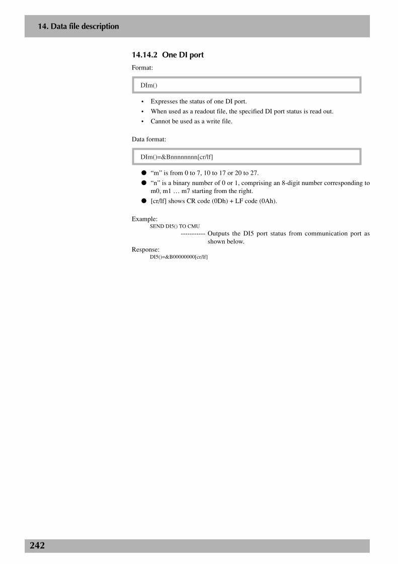
242
2
14. Data file description
14.14.2 One DI port
Format:
DIm()
• Expresses the status of one DI port.
• When used as a readout file, the specified DI port status is read out.
• Cannot be used as a write file.
Data format:
DIm()=&Bnnnnnnnn[cr/lf]
● “m” is from 0 to 7, 10 to 17 or 20 to 27.
● “n” is a binary number of 0 or 1, comprising an 8-digit number corresponding tom0, m1 … m7 starting from the right.
● [cr/lf] shows CR code (0Dh) + LF code (0Ah).
Example:SEND DI5() TO CMU
----------- Outputs the DI5 port status from communication port asshown below.
Response:DI5()=&B00000000[cr/lf]

243
2
14. Data file description
14.15 DO file
14.15.1 All DO information
Format:
DO()
• Expresses all DO information.
• When used as a readout file, all DO information is read out.
• Cannot be used as a write file.
Data format:
DO0()=&Bnnnnnnnn [cr/lf]DO1()=&Bnnnnnnnn [cr/lf] :DO27()=&Bnnnnnnnn [cr/lf][cr/lf]
● “n” is a binary number of 0 or 1, comprising an 8-digit number corresponding tom0, m1 … m7 starting from the right. (“m” is a port number.)
● [cr/lf] shows CR code (0Dh) + LF code (0Ah).
● A line containing only [cr/lf] is added at the end of the file, indicating the end ofthe file.
Example:SEND DO() TO CMU
----------- Outputs all DO information from communication port asshown below.
Response:DO0()=&B10001001[cr/lf]DO1()=&B00000010[cr/lf]DO2()=&B00000000[cr/lf]
:DO7()=&B00000000[cr/lf]DO10()=&B00000000[cr/lf]DO11()=&B00000000[cr/lf]DO12()=&B00000000[cr/lf]
:DO17()=&B00000000[cr/lf]DO20()=&B00000000[cr/lf]
:DO26()=&B00000000[cr/lf]DO27()=&B00000000[cr/lf][cr/lf]
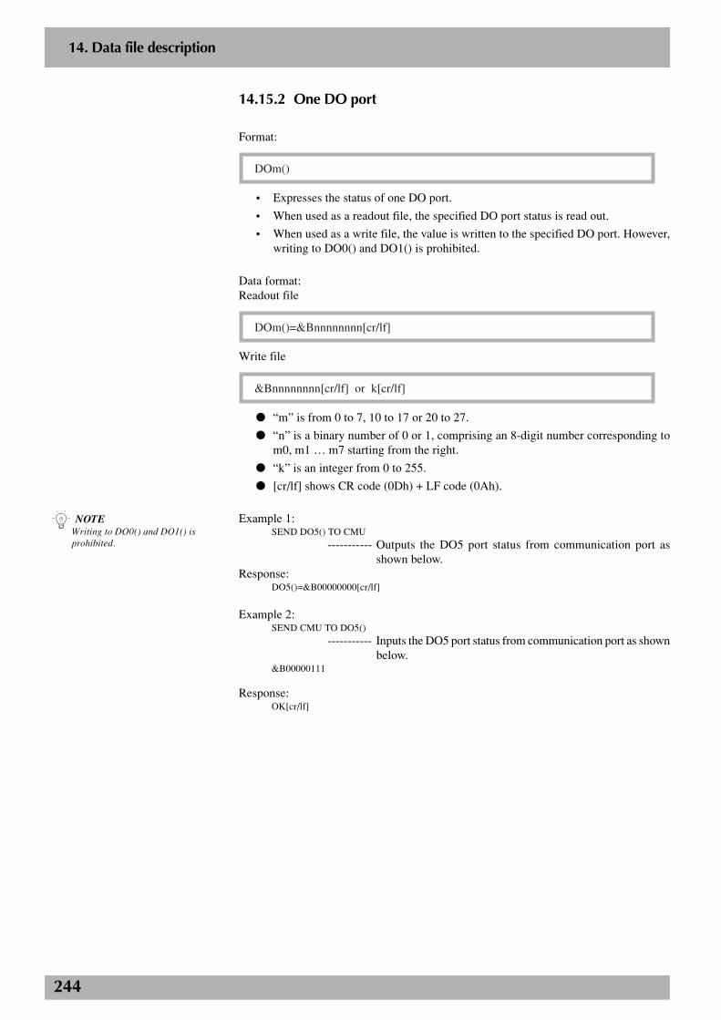
244
2
14. Data file description
14.15.2 One DO port
Format:
DOm()
• Expresses the status of one DO port.
• When used as a readout file, the specified DO port status is read out.
• When used as a write file, the value is written to the specified DO port. However,writing to DO0() and DO1() is prohibited.
Data format:Readout file
DOm()=&Bnnnnnnnn[cr/lf]
Write file
&Bnnnnnnnn[cr/lf] or k[cr/lf]
● “m” is from 0 to 7, 10 to 17 or 20 to 27.
● “n” is a binary number of 0 or 1, comprising an 8-digit number corresponding tom0, m1 … m7 starting from the right.
● “k” is an integer from 0 to 255.
● [cr/lf] shows CR code (0Dh) + LF code (0Ah).
Example 1:SEND DO5() TO CMU
----------- Outputs the DO5 port status from communication port asshown below.
Response:DO5()=&B00000000[cr/lf]
Example 2:SEND CMU TO DO5()
----------- Inputs the DO5 port status from communication port as shownbelow.
&B00000111
Response:OK[cr/lf]
n NOTEWriting to DO0() and DO1() isprohibited.
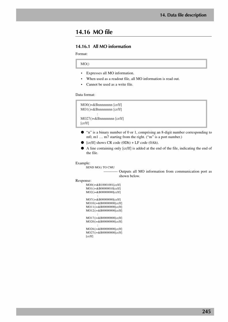
245
2
14. Data file description
14.16 MO file
14.16.1 All MO information
Format:
MO()
• Expresses all MO information.
• When used as a readout file, all MO information is read out.
• Cannot be used as a write file.
Data format:
MO0()=&Bnnnnnnnn [cr/lf]MO1()=&Bnnnnnnnn [cr/lf] :MO27()=&Bnnnnnnnn [cr/lf][cr/lf]
● “n” is a binary number of 0 or 1, comprising an 8-digit number corresponding tom0, m1 … m7 starting from the right. (“m” is a port number.)
● [cr/lf] shows CR code (0Dh) + LF code (0Ah).
● A line containing only [cr/lf] is added at the end of the file, indicating the end ofthe file.
Example:SEND MO() TO CMU
----------- Outputs all MO information from communication port asshown below.
Response:MO0()=&B10001001[cr/lf]MO1()=&B00000010[cr/lf]MO2()=&B00000000[cr/lf]
:MO7()=&B00000000[cr/lf]MO10()=&B00000000[cr/lf]MO11()=&B00000000[cr/lf]MO12()=&B00000000[cr/lf]
:MO17()=&B00000000[cr/lf]MO20()=&B00000000[cr/lf]
:MO26()=&B00000000[cr/lf]MO27()=&B00000000[cr/lf][cr/lf]

246
2
14. Data file description
14.16.2 One MO port
Format:
MOm()
• Expresses the status of one MO port.
• When used as a readout file, the specified MO port status is read out.
• When used as a write file, the value is written to the specified MO port. However,writing to MO0() and MO1() is prohibited.
Data format:Readout file
MOm()=&Bnnnnnnnn[cr/lf]
Write file
&Bnnnnnnnn[cr/lf] or k[cr/lf]
● “m” is from 0 to 7, 10 to 17 or 20 to 27.
● “n” is a binary number of 0 or 1, comprising an 8-digit number corresponding tom0, m1 … m7 starting from the right.
● “k” is an integer from 0 to 255.
● [cr/lf] shows CR code (0Dh) + LF code (0Ah).
Example 1:SEND MO5() TO CMU
----------- Outputs the MO5 port status from communication port asshown below.
Response:MO5()=&B00000000[cr/lf]
Example 2:SEND CMU TO MO5()
----------- Inputs the MO5 port status from communication port as shownbelow.
&B00000111
Response:OK[cr/lf]
n NOTEWriting to MO0() and MO1() isprohibited.

247
2
14. Data file description
14.17 LO file
14.17.1 All LO information
Format:
LO()
• Expresses all LO information.
• When used as a readout file, all LO information is read out.
• Cannot be used as a write file.
Data format:
LO0()=&Bnnnnnnnn [cr/lf][cr/lf]
● “n” is a binary number of 0 or 1, comprising an 8-digit number corresponding to00, 01 … 07 starting from the right.
● [cr/lf] shows CR code (0Dh) + LF code (0Ah).
● A line containing only [cr/lf] is added at the end of the file, indicating the end ofthe file.
Example:SEND LO() TO CMU
----------- Outputs all LO information from communication port asshown below.
Response:LO0()=&B10001001[cr/lf][cr/lf]
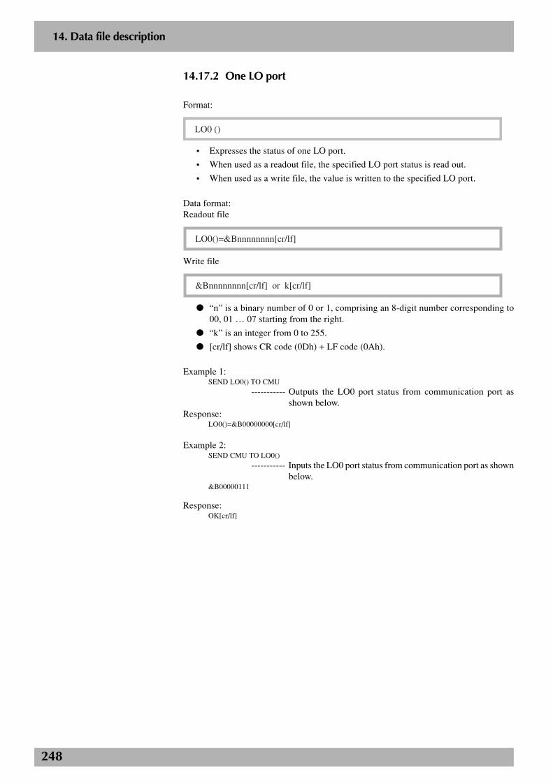
248
2
14. Data file description
14.17.2 One LO port
Format:
LO0 ()
• Expresses the status of one LO port.
• When used as a readout file, the specified LO port status is read out.
• When used as a write file, the value is written to the specified LO port.
Data format:Readout file
LO0()=&Bnnnnnnnn[cr/lf]
Write file
&Bnnnnnnnn[cr/lf] or k[cr/lf]
● “n” is a binary number of 0 or 1, comprising an 8-digit number corresponding to00, 01 … 07 starting from the right.
● “k” is an integer from 0 to 255.
● [cr/lf] shows CR code (0Dh) + LF code (0Ah).
Example 1:SEND LO0() TO CMU
----------- Outputs the LO0 port status from communication port asshown below.
Response:LO0()=&B00000000[cr/lf]
Example 2:SEND CMU TO LO0()
----------- Inputs the LO0 port status from communication port as shownbelow.
&B00000111
Response:OK[cr/lf]
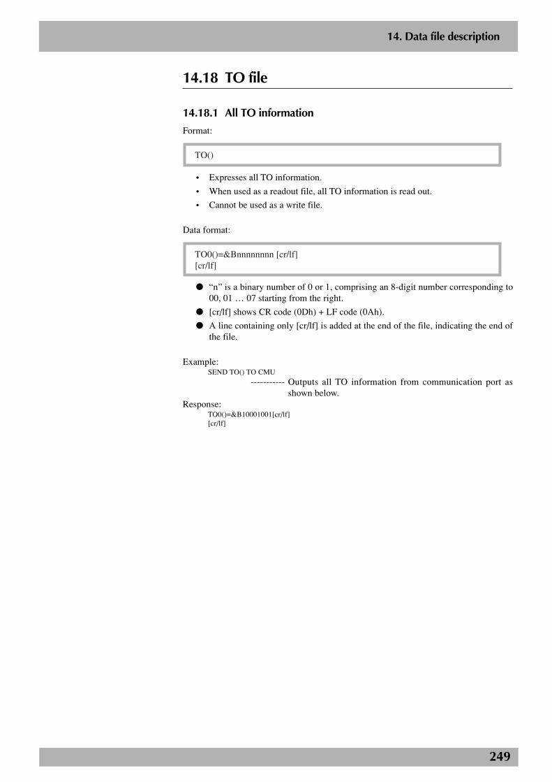
249
2
14. Data file description
14.18 TO file
14.18.1 All TO information
Format:
TO()
• Expresses all TO information.
• When used as a readout file, all TO information is read out.
• Cannot be used as a write file.
Data format:
TO0()=&Bnnnnnnnn [cr/lf][cr/lf]
● “n” is a binary number of 0 or 1, comprising an 8-digit number corresponding to00, 01 … 07 starting from the right.
● [cr/lf] shows CR code (0Dh) + LF code (0Ah).
● A line containing only [cr/lf] is added at the end of the file, indicating the end ofthe file.
Example:SEND TO() TO CMU
----------- Outputs all TO information from communication port asshown below.
Response:TO0()=&B10001001[cr/lf][cr/lf]

250
2
14. Data file description
14.18.2 One TO port
Format:
TO0()
• Expresses the status of one TO port.
• When used as a readout file, the specified TO port status is read out.
• When used as a write file, the value is written to the specified TO port.
Data format:Readout file
TO0()=&Bnnnnnnnn[cr/lf]
Write file
&Bnnnnnnnn[cr/lf] or k[cr/lf]
● “n” is a binary number of 0 or 1, comprising an 8-digit number corresponding to00, 01 … 07 starting from the right.
● “k” is an integer from 0 to 255.
● [cr/lf] shows CR code (0Dh) + LF code (0Ah).
Example 1:SEND TO0() TO CMU
----------- Outputs the TO0 port status from communication port asshown below.
Response:TO0()=&B00000000[cr/lf]
Example 2:SEND CMU TO TO0()
----------- Inputs the TO0 port status from communication port as shownbelow.
&B00000111
Response:OK[cr/lf]

251
2
14. Data file description
14.19 SI file
14.19.1 All SI information
Format:
SI()
• Expresses all SI information.
• When used as a readout file, all SI information is read out.
• Cannot be used as a write file.
Data format:
SI0()=&Bnnnnnnnn [cr/lf]SI1()=&Bnnnnnnnn [cr/lf] :SI27()=&Bnnnnnnnn [cr/lf][cr/lf]
● “n” is a binary number of 0 or 1, comprising an 8-digit number corresponding tom0, m1 … m7 starting from the right. (“m” is a port number.)
● [cr/lf] shows CR code (0Dh) + LF code (0Ah).
● A line containing only [cr/lf] is added at the end of the file, indicating the end ofthe file.
Example:SEND SI() TO CMU
----------- Outputs all SI information from communication port as shownbelow.
Response:SI0()=&B10001001[cr/lf]SI1()=&B00000010[cr/lf]SI2()=&B00000000[cr/lf]
:SI7()=&B00000000[cr/lf]SI10()=&B00000000[cr/lf]SI11()=&B00000000[cr/lf]SI12()=&B00000000[cr/lf]
:SI17()=&B00000000[cr/lf]SI20()=&B00000000[cr/lf]
:SI26()=&B00000000[cr/lf]SI27()=&B00000000[cr/lf][cr/lf]

252
2
14. Data file description
14.19.2 One SI port
Format:
SIm()
• Expresses the status of one SI port.
• When used as a readout file, the specified SI port status is read out.
• Cannot be used as a write file.
Data format:
SIm()=&Bnnnnnnnn[cr/lf]
● “m” is from 0 to 7, 10 to 17 or 20 to 27.
● “n” is a binary number of 0 or 1, comprising an 8-digit number corresponding tom0, m1 … m7 starting from the right.
● [cr/lf] shows CR code (0Dh) + LF code (0Ah).
Example:SEND SI5() TO CMU
----------- Outputs the SI5 port status from communication port as shownbelow.
Response:SI5()=&B00000000[cr/lf]

253
2
14. Data file description
14.20 SO file
14.20.1 All SO information
Format:
SO()
• Expresses all SO information.
• When used as a readout file, all SO information is read out.
• Cannot be used as a write file.
Data format:
SO0()=&Bnnnnnnnn [cr/lf]SO1()=&Bnnnnnnnn [cr/lf] :SO27()=&Bnnnnnnnn [cr/lf][cr/lf]
● “n” is a binary number of 0 or 1, comprising an 8-digit number corresponding tom0, m1 … m7 starting from the right. (“m” is a port number.)
● [cr/lf] shows CR code (0Dh) + LF code (0Ah).
● A line containing only [cr/lf] is added at the end of the file, indicating the end ofthe file.
Example:SEND SO() TO CMU
----------- Outputs all SO information from communication port asshown below.
Response:SO0()=&B10001001[cr/lf]SO1()=&B00000010[cr/lf]SO2()=&B00000000[cr/lf]
:SO7()=&B00000000[cr/lf]SO10()=&B00000000[cr/lf]SO11()=&B00000000[cr/lf]SO12()=&B00000000[cr/lf]
:SO17()=&B00000000[cr/lf]SO20()=&B00000000[cr/lf]
:SO26()=&B00000000[cr/lf]SO27()=&B00000000[cr/lf][cr/lf]
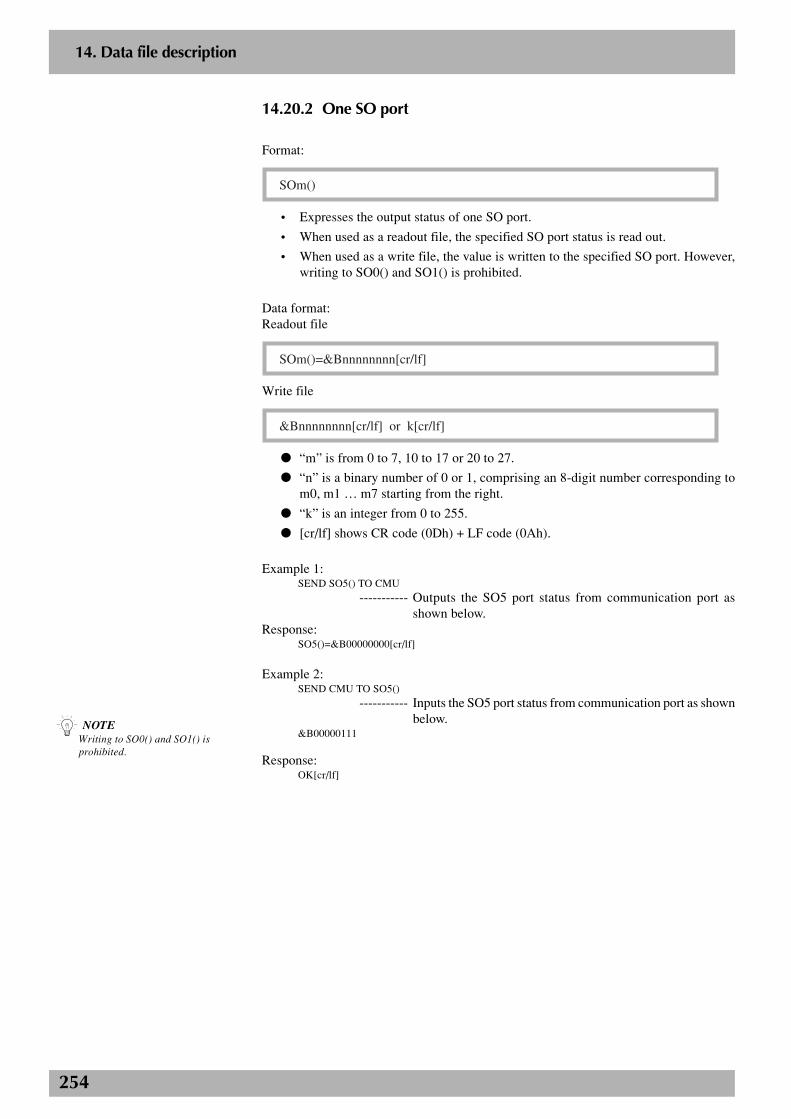
254
2
14. Data file description
14.20.2 One SO port
Format:
SOm()
• Expresses the output status of one SO port.
• When used as a readout file, the specified SO port status is read out.
• When used as a write file, the value is written to the specified SO port. However,writing to SO0() and SO1() is prohibited.
Data format:Readout file
SOm()=&Bnnnnnnnn[cr/lf]
Write file
&Bnnnnnnnn[cr/lf] or k[cr/lf]
● “m” is from 0 to 7, 10 to 17 or 20 to 27.
● “n” is a binary number of 0 or 1, comprising an 8-digit number corresponding tom0, m1 … m7 starting from the right.
● “k” is an integer from 0 to 255.
● [cr/lf] shows CR code (0Dh) + LF code (0Ah).
Example 1:SEND SO5() TO CMU
----------- Outputs the SO5 port status from communication port asshown below.
Response:SO5()=&B00000000[cr/lf]
Example 2:SEND CMU TO SO5()
----------- Inputs the SO5 port status from communication port as shownbelow.
&B00000111
Response:OK[cr/lf]
n NOTEWriting to SO0() and SO1() isprohibited.
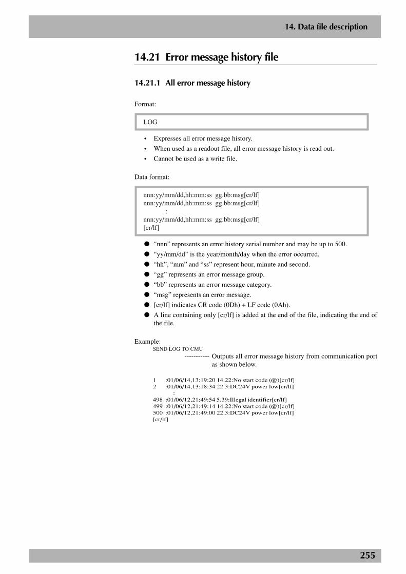
255
2
14. Data file description
14.21 Error message history file
14.21.1 All error message history
Format:
LOG
• Expresses all error message history.
• When used as a readout file, all error message history is read out.
• Cannot be used as a write file.
Data format:
nnn:yy/mm/dd,hh:mm:ss gg.bb:msg[cr/lf]nnn:yy/mm/dd,hh:mm:ss gg.bb:msg[cr/lf] :nnn:yy/mm/dd,hh:mm:ss gg.bb:msg[cr/lf][cr/lf]
● “nnn” represents an error history serial number and may be up to 500.
● “yy/mm/dd” is the year/month/day when the error occurred.
● “hh”, “mm” and “ss” represent hour, minute and second.
● “gg” represents an error message group.
● “bb” represents an error message category.
● “msg” represents an error message.
● [cr/lf] indicates CR code (0Dh) + LF code (0Ah).
● A line containing only [cr/lf] is added at the end of the file, indicating the end ofthe file.
Example:SEND LOG TO CMU
----------- Outputs all error message history from communication portas shown below.
1 :01/06/14,13:19:20 14.22:No start code (@)[cr/lf]2 :01/06/14,13:18:34 22.3:DC24V power low[cr/lf]
:498 :01/06/12,21:49:54 5.39:Illegal identifier[cr/lf]499 :01/06/12,21:49:14 14.22:No start code (@)[cr/lf]500 :01/06/12,21:49:00 22.3:DC24V power low[cr/lf][cr/lf]
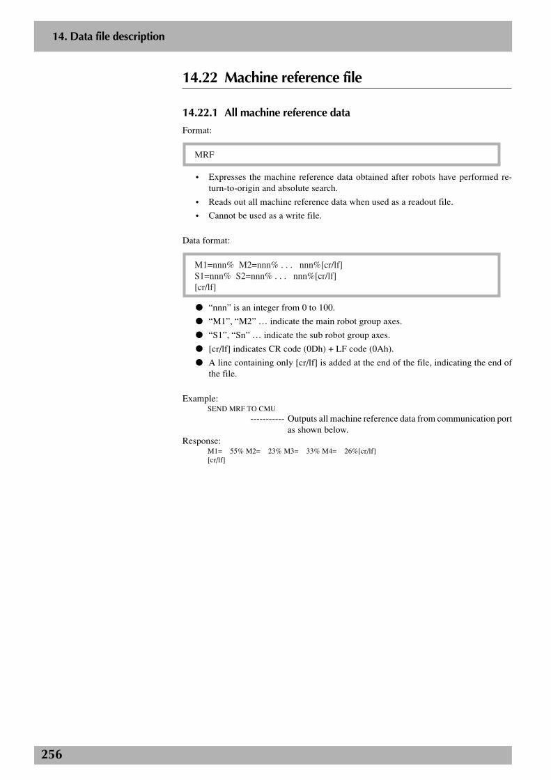
256
2
14. Data file description
14.22 Machine reference file
14.22.1 All machine reference data
Format:
MRF
• Expresses the machine reference data obtained after robots have performed re-turn-to-origin and absolute search.
• Reads out all machine reference data when used as a readout file.
• Cannot be used as a write file.
Data format:
M1=nnn% M2=nnn% . . . nnn%[cr/lf]S1=nnn% S2=nnn% . . . nnn%[cr/lf][cr/lf]
● “nnn” is an integer from 0 to 100.
● “M1”, “M2” … indicate the main robot group axes.
● “S1”, “Sn” … indicate the sub robot group axes.
● [cr/lf] indicates CR code (0Dh) + LF code (0Ah).
● A line containing only [cr/lf] is added at the end of the file, indicating the end ofthe file.
Example:SEND MRF TO CMU
----------- Outputs all machine reference data from communication portas shown below.
Response:M1= 55% M2= 23% M3= 33% M4= 26%[cr/lf][cr/lf]
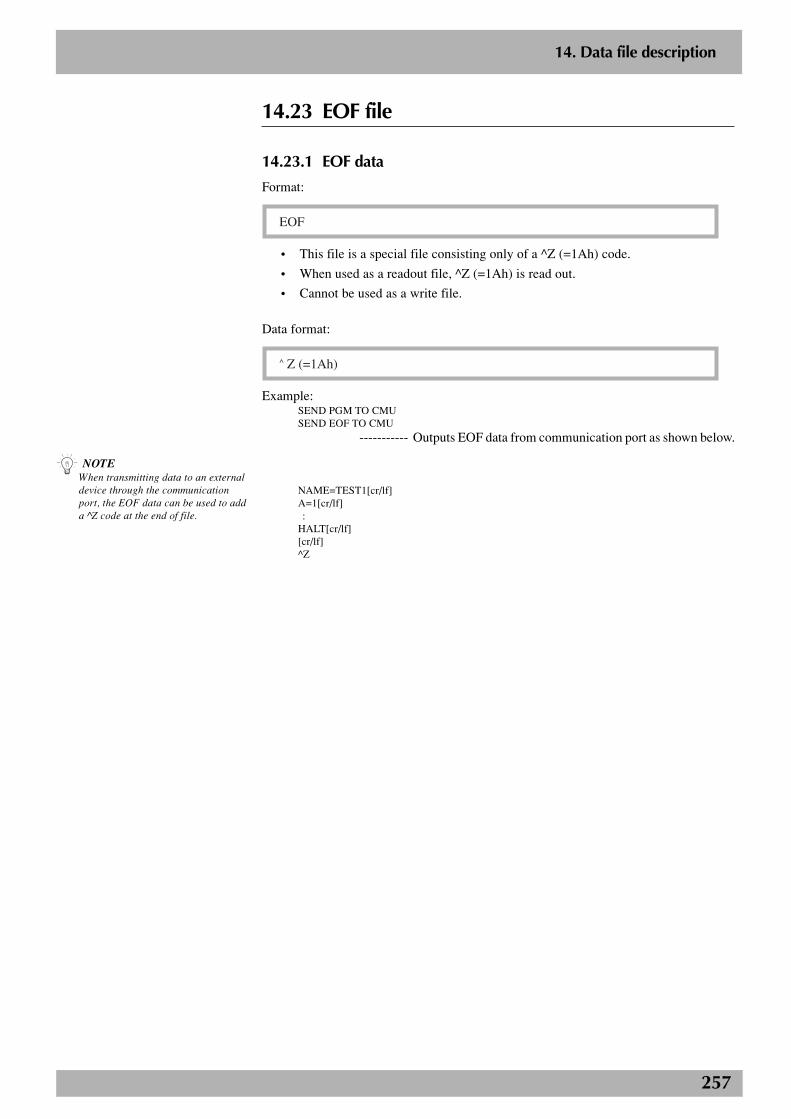
257
2
14. Data file description
14.23 EOF file
14.23.1 EOF data
Format:
EOF
• This file is a special file consisting only of a ^Z (=1Ah) code.
• When used as a readout file, ^Z (=1Ah) is read out.
• Cannot be used as a write file.
Data format:
^ Z (=1Ah)
Example:SEND PGM TO CMUSEND EOF TO CMU
----------- Outputs EOF data from communication port as shown below.
NAME=TEST1[cr/lf]A=1[cr/lf] :HALT[cr/lf][cr/lf]^Z
n NOTEWhen transmitting data to an externaldevice through the communicationport, the EOF data can be used to adda ^Z code at the end of file.
258
2
14. Data file description
14.24 Serial port communication file
14.24.1 Serial port communication file
Format:
CMU
• Expresses the serial communication port.
• Depends on the various data formats.
Example:SEND PNT TO CMU
----------- Outputs all point data from communication port.SEND CMU TO PNT
----------- Inputs all point data from communication port.
259
2
14. Data file description
14.25 SIW file
14.25.1 All SIW
Format:
SIW()
• Expresses all SIW data.
• Reads out all SIW information in hexadecimal digit when used as a readout file.
• Cannot be used as a write file.
Data format:
SIW( 0)=&Hnnnn [cr/lf]SIW( 1)=&Hnnnn [cr/lf] :SIW(15)=&Hnnnn [cr/lf][ cr/lf]
● “n” represents a 4-digit number from 0 to 9 and A to F.
● [cr/lf] indicates CR code (0Dh) + LF code (0Ah).
● A line containing only [cr/lf] is added at the end of the file, indicating the end ofthe file.
Example:SEND SIW() TO CMU
----------- Outputs all SIW data from communication port as shownbelow.
Response:SIW( 0)=&H1001[cr/lf]SIW( 1)=&H0010[cr/lf]SIW( 2)=&H0000[cr/lf] :SIW(15)=&H0000[cr/lf][cr/lf]
c CAUTIONSIW is only available from softwareversion 8.08 onwards.

260
2
14. Data file description
14.25.2 One SIW data
Format:
SIW(m)
• Expresses one SIW state.
• Reads out the designated SIW information in hexadecimal when used as a readoutfile.
• Cannot be used as a write file.
Data format:
SIW(m)=&Hnnnn [cr/lf]
● “m” represents a number from 0 to 15.
● “n” represents a 4-digit number from 0 to 9 and A to F.
● [cr/lf] indicates CR code (0Dh) + LF code (0Ah).
Example:SEND SIW(5) TO CMU
----------- Outputs SIW (5) from communication port as shown below.Response:
SIW( 5)=&H1001[cr/lf]
c CAUTIONSIW is only available from softwareversion 8.08 onwards.
261
2
14. Data file description
14.26 SOW file
14.26.1 All SOW
Format:
SOW()
• Expresses all SOW data.
• Reads out all SOW information in hexadecimal when used as a readout file.
• Cannot be used as a write file.
Data format:
SOW( 0)=&Hnnnn [cr/lf]SOW( 1)=&Hnnnn [cr/lf] :SOW(15)=&Hnnnn [cr/lf][ cr/lf]
● “n” represents a 4-digit number from 0 to 9 and A to F.
● [cr/lf] indicates CR code (0Dh) + LF code (0Ah).
● A line containing only [cr/lf] is added at the end of the file, indicating the end ofthe file.
Example:SEND SOW() TO CMU
----------- Outputs all SOW data from communication port as shownbelow.
Response:SOW( 0)=&H1001[cr/lf]SOW( 1)=&H0010[cr/lf]SOW( 2)=&H0000[cr/lf] :SOW(15)=&H0000[cr/lf][cr/lf]
c CAUTIONSOW is only available from softwareversion 8.08 onwards.
262
2
14. Data file description
14.26.2 One SOW data
Format:
SOW(m)
• Expresses one SOW state.
• Reads out the designated SOW information in hexadecimal when used as a readoutfile.
• When used as a write file, the value is written to the designated SOW. However,writing to SOW (0) and SOW (1) is prohibited.
Data format:
SOW(m)=&Hnnnn [cr/lf]
● “m” represents a number from 2 to 15.
● “n” represents a 4-digit number from 0 to 9 and A to F.
● [cr/lf] indicates CR code (0Dh) + LF code (0Ah).
Example1:SEND SOW(5) TO CMU
----------- Outputs SOW (5) from communication port as shown below.Response:
SOW( 5)=&H1001[cr/lf]
Example2:SEND CMU TO SOW(5)
----------- Outputs SOW (5) from communication port as shown below.&H1001
Response:OK[cr/lf]
n NOTEWriting to SOW (0) and SOW (1) isprohibited.
c CAUTIONSOW is only available from softwareversion 8.08 onwards.
263
2
14. Data file description
14.27 Ethernet port communication file
14.27.1 Ethernet port communication file
Format:
ETH
• Expresses the Ethernet port.
• Depends on the various data formats.
Example:SEND PNT TO ETH
----------- Outputs all point data from the Ethernet port.SEND ETH TO PNT
----------- Inputs all point data from the Ethernet port.
c CAUTIONETH is only available from softwareversion 8.22 onwards.
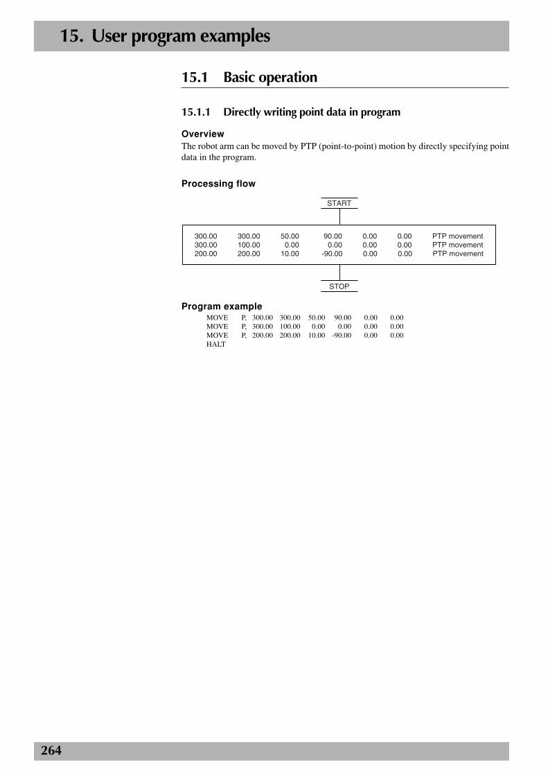
264
15. User program examples
15.1 Basic operation
15.1.1 Directly writing point data in program
OverviewThe robot arm can be moved by PTP (point-to-point) motion by directly specifying pointdata in the program.
Processing flow
300.00 300.00 50.00 90.00 0.00 0.00 PTP movement300.00 100.00 0.00 0.00 0.00 0.00 PTP movement200.00 200.00 10.00 -90.00 0.00 0.00 PTP movement
START
STOP
Program exampleMOVE P, 300.00 300.00 50.00 90.00 0.00 0.00MOVE P, 300.00 100.00 0.00 0.00 0.00 0.00MOVE P, 200.00 200.00 10.00 -90.00 0.00 0.00HALT
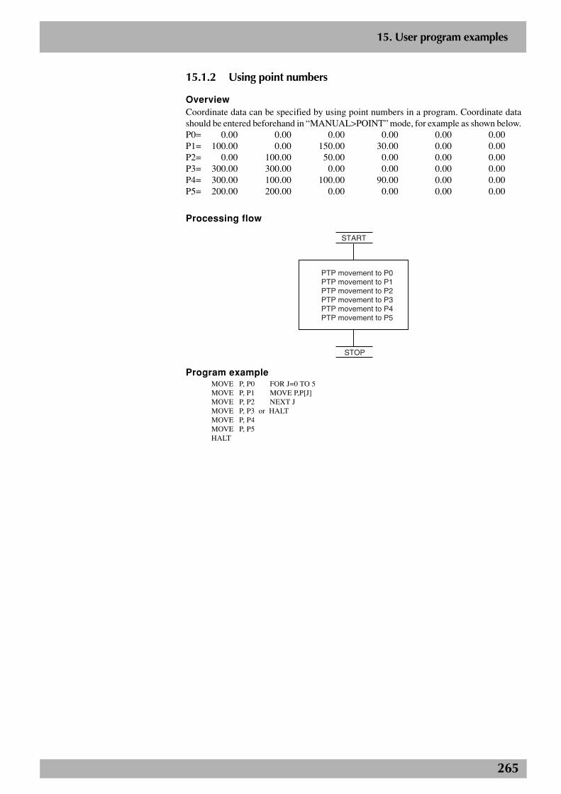
265
2
15. User program examples
15.1.2 Using point numbers
OverviewCoordinate data can be specified by using point numbers in a program. Coordinate datashould be entered beforehand in “MANUAL>POINT” mode, for example as shown below.P0= 0.00 0.00 0.00 0.00 0.00 0.00P1= 100.00 0.00 150.00 30.00 0.00 0.00P2= 0.00 100.00 50.00 0.00 0.00 0.00P3= 300.00 300.00 0.00 0.00 0.00 0.00P4= 300.00 100.00 100.00 90.00 0.00 0.00P5= 200.00 200.00 0.00 0.00 0.00 0.00
Processing flow
PTP movement to P0PTP movement to P1PTP movement to P2PTP movement to P3PTP movement to P4PTP movement to P5
START
STOP
Program exampleMOVE P, P0 FOR J=0 TO 5MOVE P, P1 MOVE P,P[J]MOVE P, P2 NEXT JMOVE P, P3 or HALTMOVE P, P4MOVE P, P5HALT
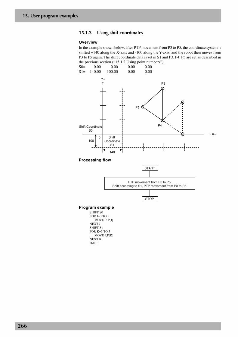
266
2
15. User program examples
15.1.3 Using shift coordinates
OverviewIn the example shown below, after PTP movement from P3 to P5, the coordinate system isshifted +140 along the X-axis and -100 along the Y-axis, and the robot then moves fromP3 to P5 again. The shift coordinate data is set in S1 and P3, P4, P5 are set as described inthe previous section (“15.1.2 Using point numbers”).S0= 0.00 0.00 0.00 0.00S1= 140.00 -100.00 0.00 0.00
P3
P5
P4Shift CoordinateS0
Shift Coordinate
S1
0
140
100
X+→
↑Y+
Processing flow
PTP movement from P3 to P5.Shift according to S1, PTP movement from P3 to P5.
START
STOP
Program exampleSHIFT S0FOR J=3 TO 5
MOVE P, P[J]NEXT JSHIFT S1FOR K=3 TO 5
MOVE P,P[K]NEXT KHALT
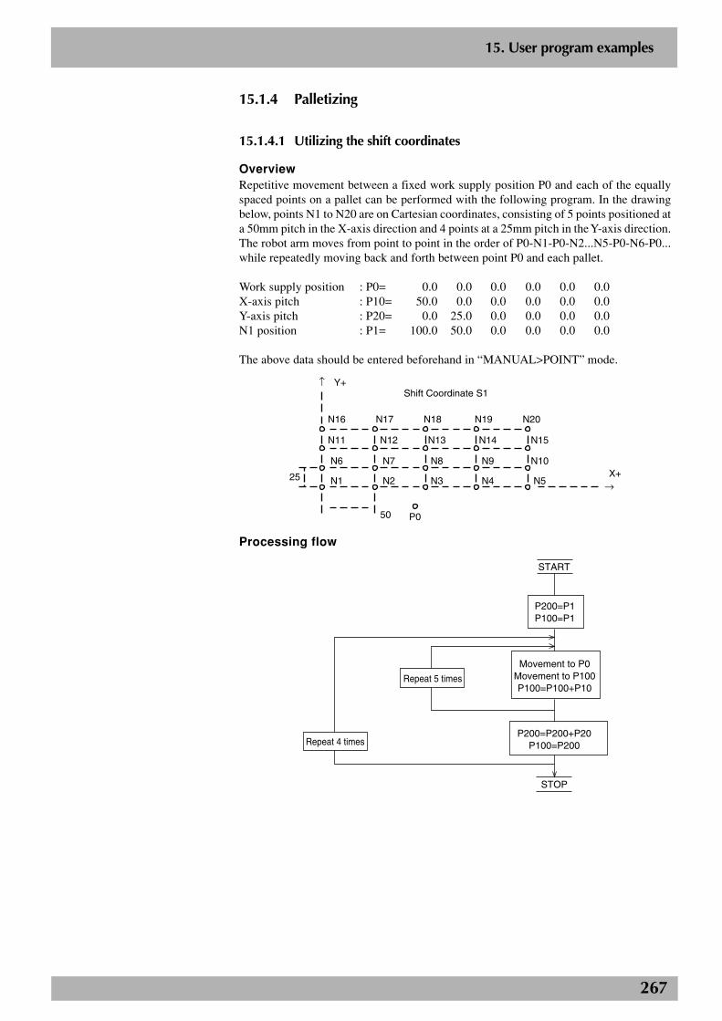
267
2
15. User program examples
15.1.4 Palletizing
15.1.4.1 Utilizing the shift coordinates
OverviewRepetitive movement between a fixed work supply position P0 and each of the equallyspaced points on a pallet can be performed with the following program. In the drawingbelow, points N1 to N20 are on Cartesian coordinates, consisting of 5 points positioned ata 50mm pitch in the X-axis direction and 4 points at a 25mm pitch in the Y-axis direction.The robot arm moves from point to point in the order of P0-N1-P0-N2...N5-P0-N6-P0...while repeatedly moving back and forth between point P0 and each pallet.
Work supply position : P0= 0.0 0.0 0.0 0.0 0.0 0.0X-axis pitch : P10= 50.0 0.0 0.0 0.0 0.0 0.0Y-axis pitch : P20= 0.0 25.0 0.0 0.0 0.0 0.0N1 position : P1= 100.0 50.0 0.0 0.0 0.0 0.0
The above data should be entered beforehand in “MANUAL>POINT” mode.
Shift Coordinate S1
N16 N17 N18 N19 N20
N11 N12 N13 N14 N15
N6 N7 N8 N9 N10
N1 N2 N3 N4 N5
50
25
P0
↑
→
Y+
X+
Processing flow
START
P200=P1P100=P1
P200=P200+P20P100=P200
STOP
Movement to P0Movement to P100P100=P100+P10
Repeat 4 times
Repeat 5 times
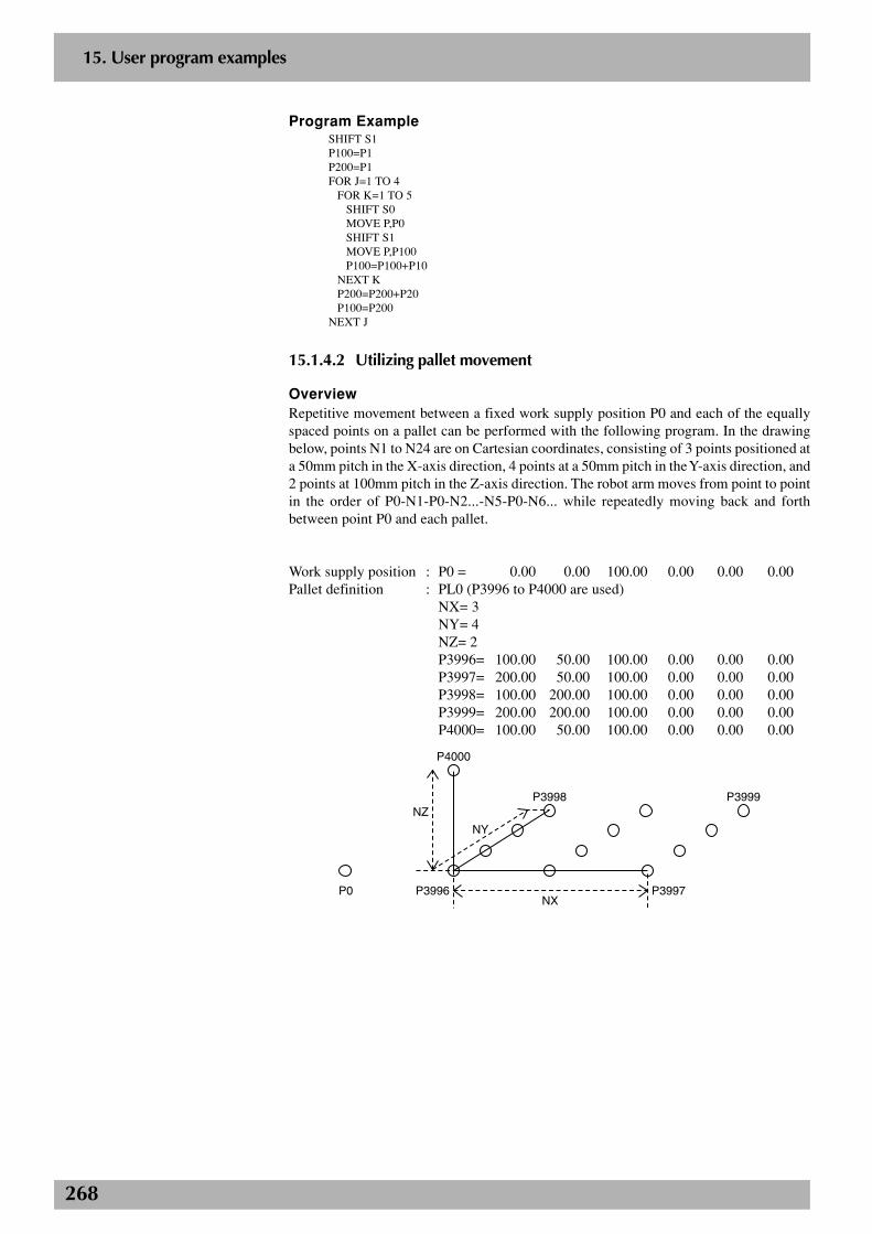
268
2
15. User program examples
Program ExampleSHIFT S1P100=P1P200=P1FOR J=1 TO 4
FOR K=1 TO 5SHIFT S0MOVE P,P0SHIFT S1MOVE P,P100P100=P100+P10
NEXT KP200=P200+P20P100=P200
NEXT J
15.1.4.2 Utilizing pallet movement
OverviewRepetitive movement between a fixed work supply position P0 and each of the equallyspaced points on a pallet can be performed with the following program. In the drawingbelow, points N1 to N24 are on Cartesian coordinates, consisting of 3 points positioned ata 50mm pitch in the X-axis direction, 4 points at a 50mm pitch in the Y-axis direction, and2 points at 100mm pitch in the Z-axis direction. The robot arm moves from point to pointin the order of P0-N1-P0-N2...-N5-P0-N6... while repeatedly moving back and forthbetween point P0 and each pallet.
Work supply position : P0 = 0.00 0.00 100.00 0.00 0.00 0.00Pallet definition : PL0 (P3996 to P4000 are used)
NX= 3NY= 4NZ= 2P3996= 100.00 50.00 100.00 0.00 0.00 0.00P3997= 200.00 50.00 100.00 0.00 0.00 0.00P3998= 100.00 200.00 100.00 0.00 0.00 0.00P3999= 200.00 200.00 100.00 0.00 0.00 0.00P4000= 100.00 50.00 100.00 0.00 0.00 0.00
P4000
P3998 P3999
P3997P3996
NZ
NX
NY
P0
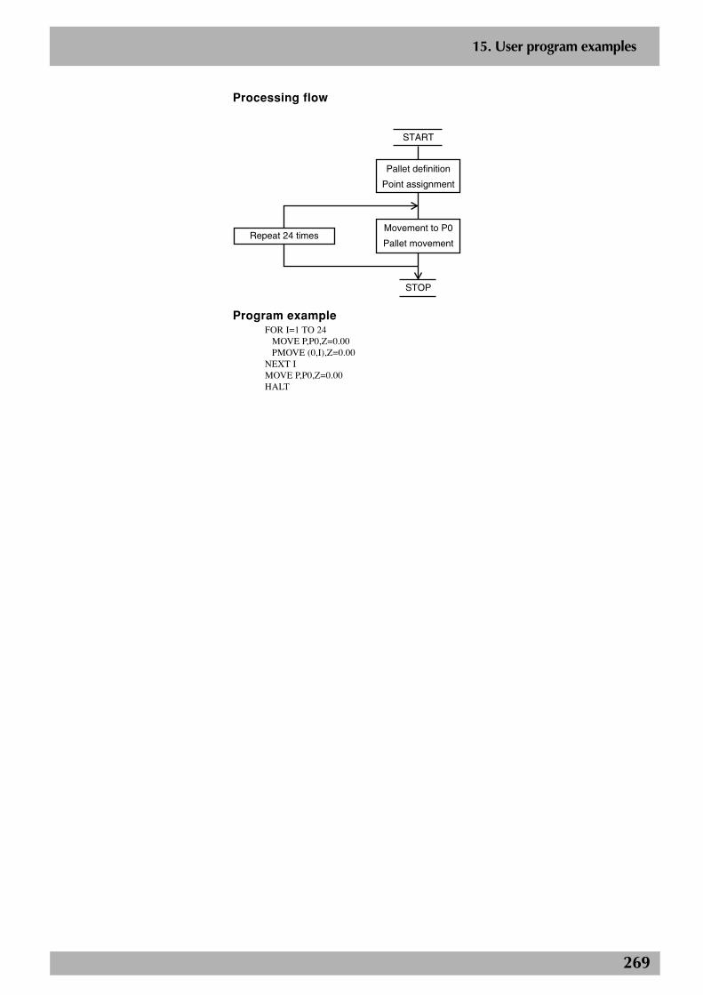
269
2
15. User program examples
Processing flow
START
STOP
Pallet definition
Point assignment
Movement to P0
Pallet movementRepeat 24 times
Program exampleFOR I=1 TO 24
MOVE P,P0,Z=0.00PMOVE (0,I),Z=0.00
NEXT IMOVE P,P0,Z=0.00HALT
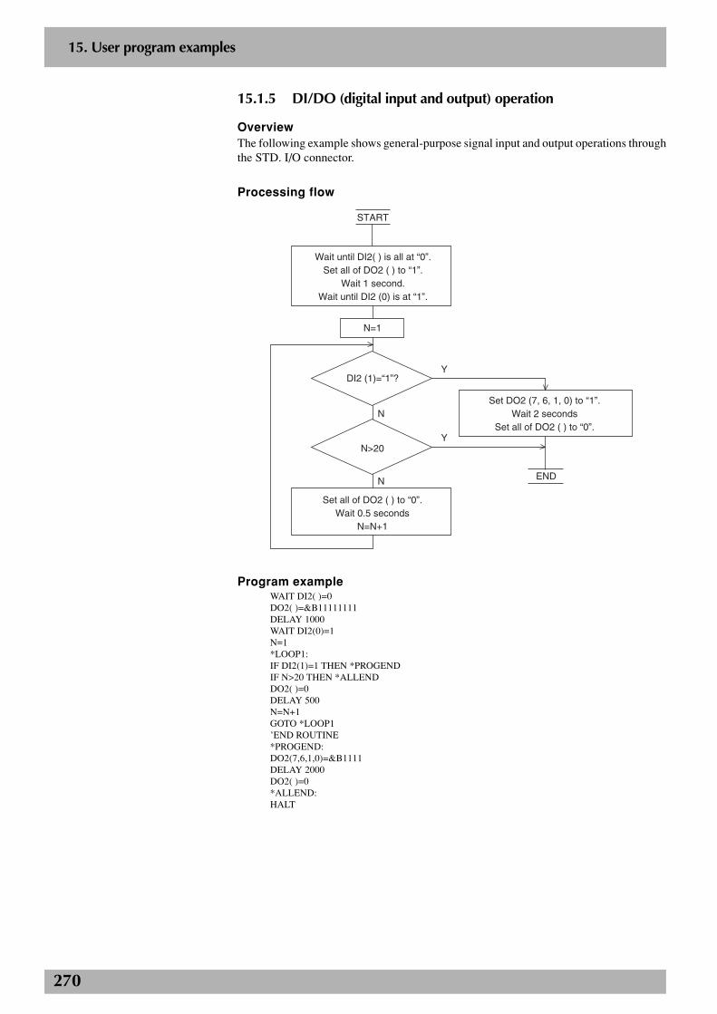
270
2
15. User program examples
15.1.5 DI/DO (digital input and output) operation
OverviewThe following example shows general-purpose signal input and output operations throughthe STD. I/O connector.
Processing flow
N
Y
Y
N
START
Wait until DI2( ) is all at “0”.Set all of DO2 ( ) to “1”.
Wait 1 second.Wait until DI2 (0) is at “1”.
N=1
DI2 (1)=“1”?
N>20
Set all of DO2 ( ) to “0”.Wait 0.5 seconds
N=N+1
Set DO2 (7, 6, 1, 0) to “1”.Wait 2 seconds
Set all of DO2 ( ) to “0”.
END
Program exampleWAIT DI2( )=0DO2( )=&B11111111DELAY 1000WAIT DI2(0)=1N=1*LOOP1:IF DI2(1)=1 THEN *PROGENDIF N>20 THEN *ALLENDDO2( )=0DELAY 500N=N+1GOTO *LOOP1’END ROUTINE*PROGEND:DO2(7,6,1,0)=&B1111DELAY 2000DO2( )=0*ALLEND:HALT
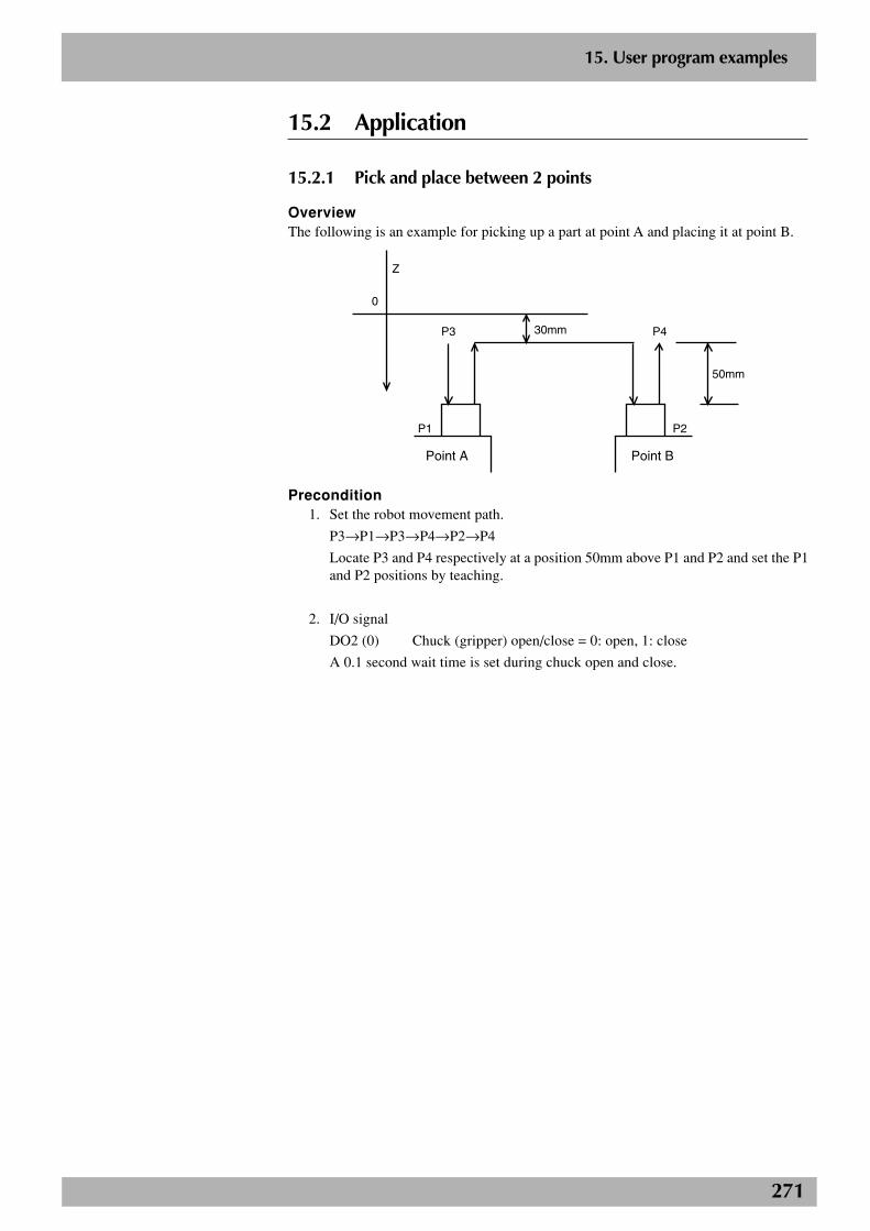
271
2
15. User program examples
15.2 Application
15.2.1 Pick and place between 2 points
OverviewThe following is an example for picking up a part at point A and placing it at point B.
0
Z
P3
P1
P4
P2
50mm
30mm
Point A Point B
Precondition1. Set the robot movement path.
P3→P1→P3→P4→P2→P4
Locate P3 and P4 respectively at a position 50mm above P1 and P2 and set the P1and P2 positions by teaching.
2. I/O signal
DO2 (0) Chuck (gripper) open/close = 0: open, 1: close
A 0.1 second wait time is set during chuck open and close.
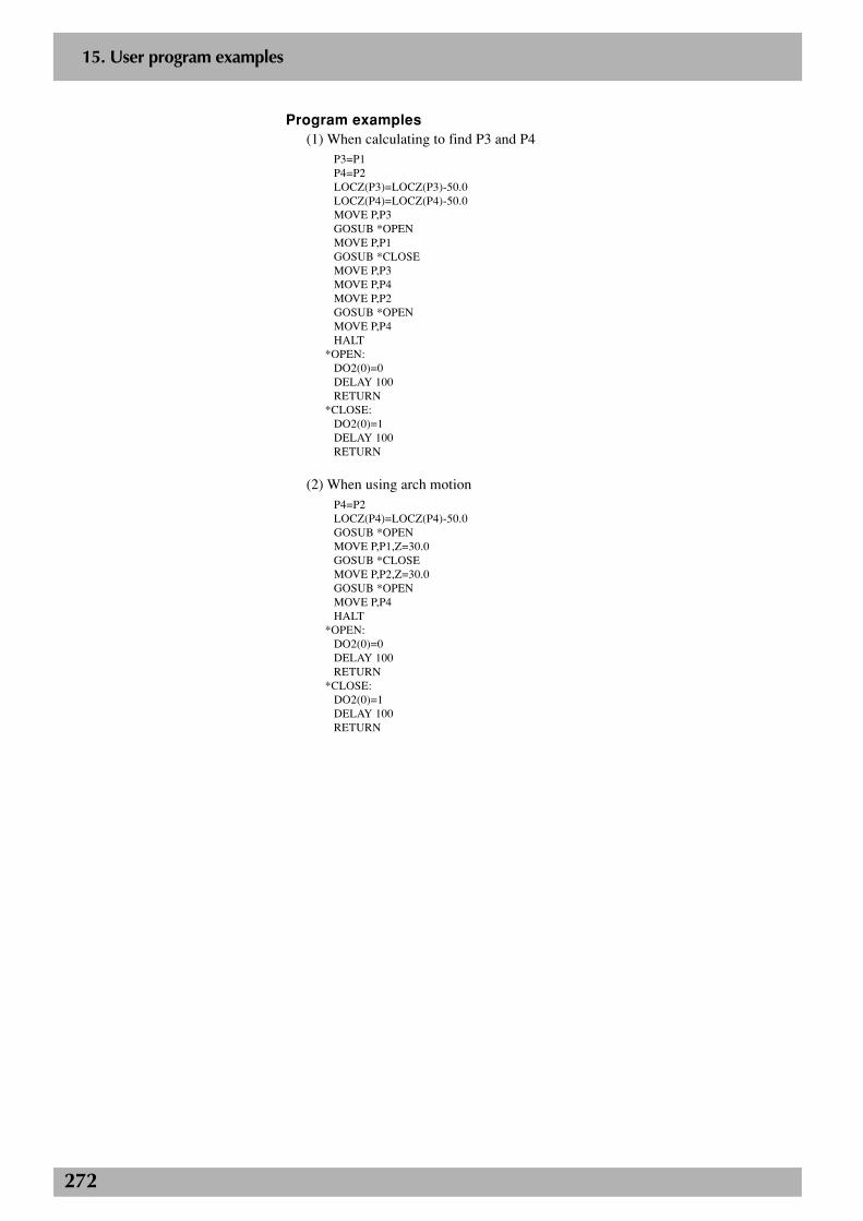
272
2
15. User program examples
Program examples(1) When calculating to find P3 and P4
P3=P1P4=P2LOCZ(P3)=LOCZ(P3)-50.0LOCZ(P4)=LOCZ(P4)-50.0MOVE P,P3GOSUB *OPENMOVE P,P1GOSUB *CLOSEMOVE P,P3MOVE P,P4MOVE P,P2GOSUB *OPENMOVE P,P4HALT
*OPEN:DO2(0)=0DELAY 100RETURN
*CLOSE:DO2(0)=1DELAY 100RETURN
(2) When using arch motionP4=P2LOCZ(P4)=LOCZ(P4)-50.0GOSUB *OPENMOVE P,P1,Z=30.0GOSUB *CLOSEMOVE P,P2,Z=30.0GOSUB *OPENMOVE P,P4HALT
*OPEN:DO2(0)=0DELAY 100RETURN
*CLOSE:DO2(0)=1DELAY 100RETURN
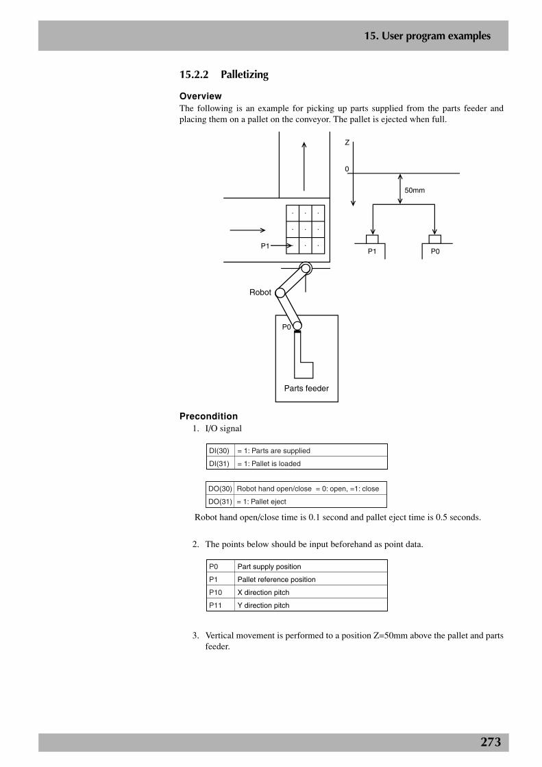
273
2
15. User program examples
15.2.2 Palletizing
OverviewThe following is an example for picking up parts supplied from the parts feeder andplacing them on a pallet on the conveyor. The pallet is ejected when full.
P1
Z
0
50mm
P1 P0
P0
Parts feeder
Robot
Precondition1. I/O signal
DI(30)
DI(31)
= 1: Parts are supplied
= 1: Pallet is loaded
DO(30)
DO(31)
Robot hand open/close = 0: open, =1: close
= 1: Pallet eject
Robot hand open/close time is 0.1 second and pallet eject time is 0.5 seconds.
2. The points below should be input beforehand as point data.
P0
P1
P10
P11
Part supply position
Pallet reference position
X direction pitch
Y direction pitch
3. Vertical movement is performed to a position Z=50mm above the pallet and partsfeeder.
274
2
15. User program examples
Program example 1WHILE -1FOR A=0 TO 2
FOR B=0 TO 2WAIT DI(31)=1WAIT DI(30)=1DO(30)=0DELAY 100MOVE P,P0,Z=50.0DO(30)=1DELAY 100P100=P1+P10*B+P11*AMOVE P,P100,Z=50.0DO(30)=0DELAY 100
NEXTNEXTDRIVE (3,0)DO(31)=1DELAY 500DO(31)=0WENDHALT
Program example 2* When defined in pallet 0
WHILE -1FOR A=1 TO 9
WAIT DI(31)=1WAIT DI(30)=1DO(30)=0DELAY 100MOVE P,P0,Z=50.0DO(30)=1DELAY 100PMOVE(0,A),Z=50.0DO(30)=0DELAY 100
NEXTDRIVE(3,0)DO(31)=1DELAY 500DO(31)=0WENDHALT
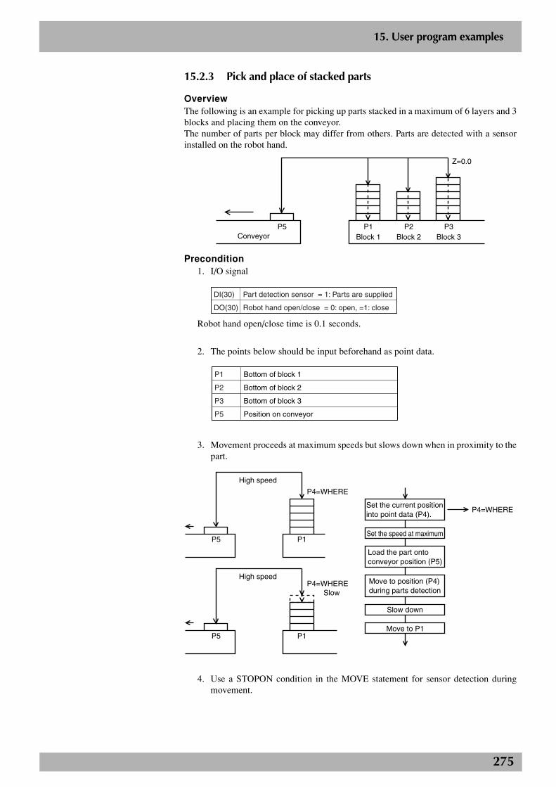
275
2
15. User program examples
15.2.3 Pick and place of stacked parts
OverviewThe following is an example for picking up parts stacked in a maximum of 6 layers and 3blocks and placing them on the conveyor.The number of parts per block may differ from others. Parts are detected with a sensorinstalled on the robot hand.
Z=0.0
ConveyorP5 P1
Block 1P2
Block 2P3
Block 3
Precondition1. I/O signal
DI(30)
DO(30)
Part detection sensor = 1: Parts are supplied
Robot hand open/close = 0: open, =1: close
Robot hand open/close time is 0.1 seconds.
2. The points below should be input beforehand as point data.
P1
P2
P3
P5
Bottom of block 1
Bottom of block 2
Bottom of block 3
Position on conveyor
3. Movement proceeds at maximum speeds but slows down when in proximity to thepart.
P5 P1
P4=WHERE
P5 P1
P4=WHERE Slow
High speed
High speed
P4=WHERESet the current position into point data (P4).
Set the speed at maximum
Load the part onto conveyor position (P5)
Move to position (P4) during parts detection
Move to P1
Slow down
4. Use a STOPON condition in the MOVE statement for sensor detection duringmovement.
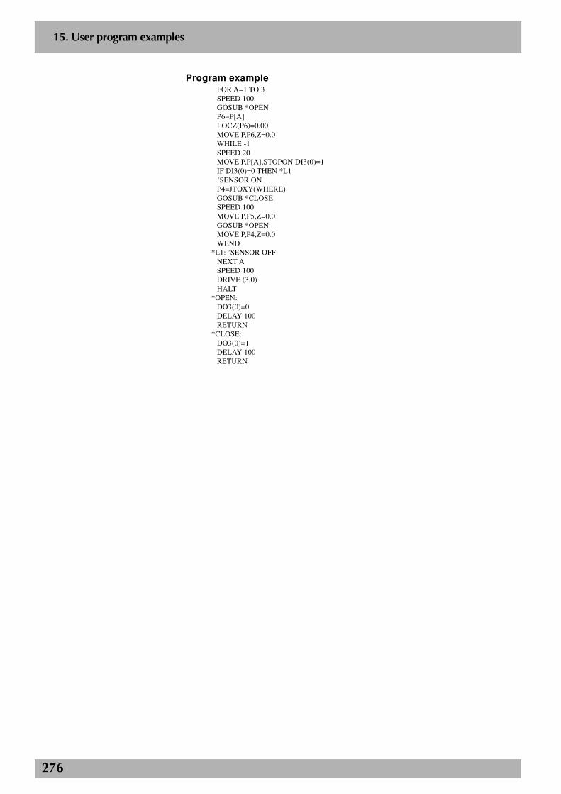
276
2
15. User program examples
Program exampleFOR A=1 TO 3SPEED 100GOSUB *OPENP6=P[A]LOCZ(P6)=0.00MOVE P,P6,Z=0.0WHILE -1SPEED 20MOVE P,P[A],STOPON DI3(0)=1IF DI3(0)=0 THEN *L1’SENSOR ONP4=JTOXY(WHERE)GOSUB *CLOSESPEED 100MOVE P,P5,Z=0.0GOSUB *OPENMOVE P,P4,Z=0.0WEND
*L1: ’SENSOR OFFNEXT ASPEED 100DRIVE (3,0)HALT
*OPEN:DO3(0)=0DELAY 100RETURN
*CLOSE:DO3(0)=1DELAY 100RETURN
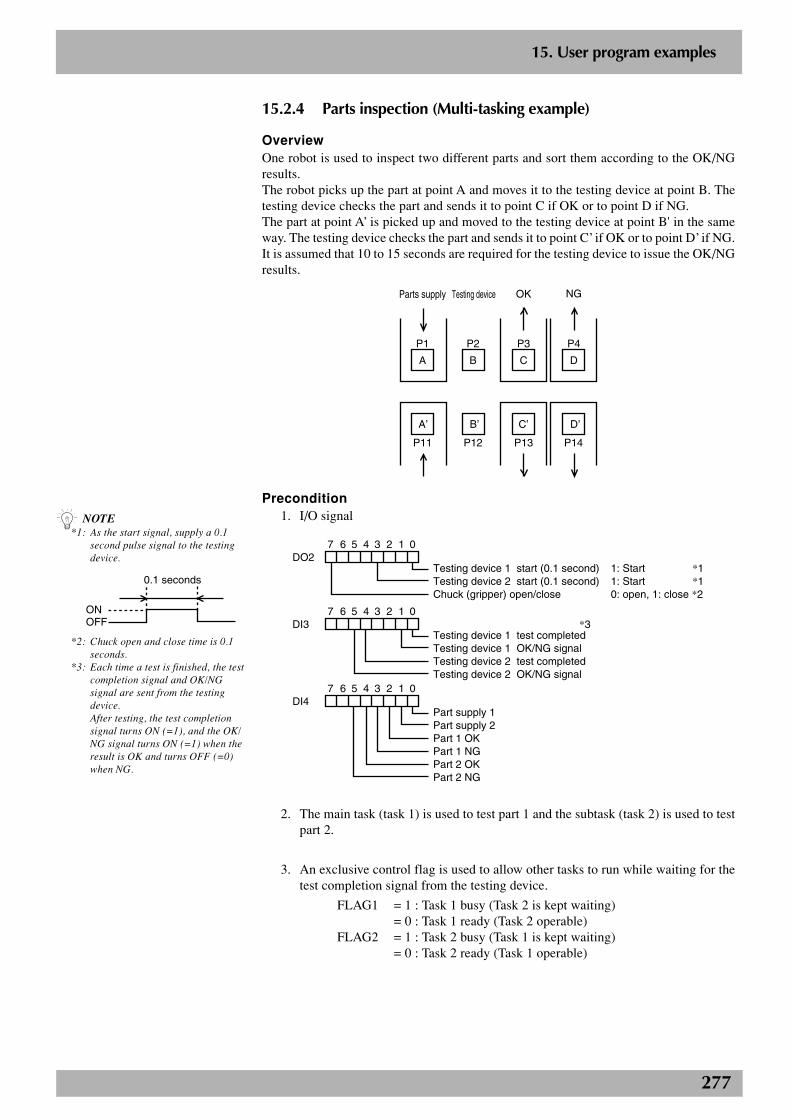
277
2
15. User program examples
15.2.4 Parts inspection (Multi-tasking example)
OverviewOne robot is used to inspect two different parts and sort them according to the OK/NGresults.The robot picks up the part at point A and moves it to the testing device at point B. Thetesting device checks the part and sends it to point C if OK or to point D if NG.The part at point A’ is picked up and moved to the testing device at point B' in the sameway. The testing device checks the part and sends it to point C’ if OK or to point D’ if NG.It is assumed that 10 to 15 seconds are required for the testing device to issue the OK/NGresults.
A
P1
B
P2
C
P3
D
P4
A’
P11
B’
P12
C’
P13
D’
P14
Parts supply Testing device OK NG
Precondition1. I/O signal
Testing device 1 start (0.1 second)Testing device 2 start (0.1 second)Chuck (gripper) open/close
DO21: Start *11: Start *10: open, 1: close *2
7 6 5 4 3 2 1 0
Testing device 1 test completedTesting device 1 OK/NG signalTesting device 2 test completedTesting device 2 OK/NG signal
DI37 6 5 4 3 2 1 0
Part supply 1 Part supply 2 Part 1 OKPart 1 NGPart 2 OKPart 2 NG
DI47 6 5 4 3 2 1 0
*3
2. The main task (task 1) is used to test part 1 and the subtask (task 2) is used to testpart 2.
3. An exclusive control flag is used to allow other tasks to run while waiting for thetest completion signal from the testing device.
FLAG1 = 1 : Task 1 busy (Task 2 is kept waiting)= 0 : Task 1 ready (Task 2 operable)
FLAG2 = 1 : Task 2 busy (Task 1 is kept waiting)= 0 : Task 2 ready (Task 1 operable)
n NOTE*1: As the start signal, supply a 0.1
second pulse signal to the testingdevice.
ONOFF
0.1 seconds
*2: Chuck open and close time is 0.1seconds.
*3: Each time a test is finished, the testcompletion signal and OK/NGsignal are sent from the testingdevice.After testing, the test completionsignal turns ON (=1), and the OK/NG signal turns ON (=1) when theresult is OK and turns OFF (=0)when NG.
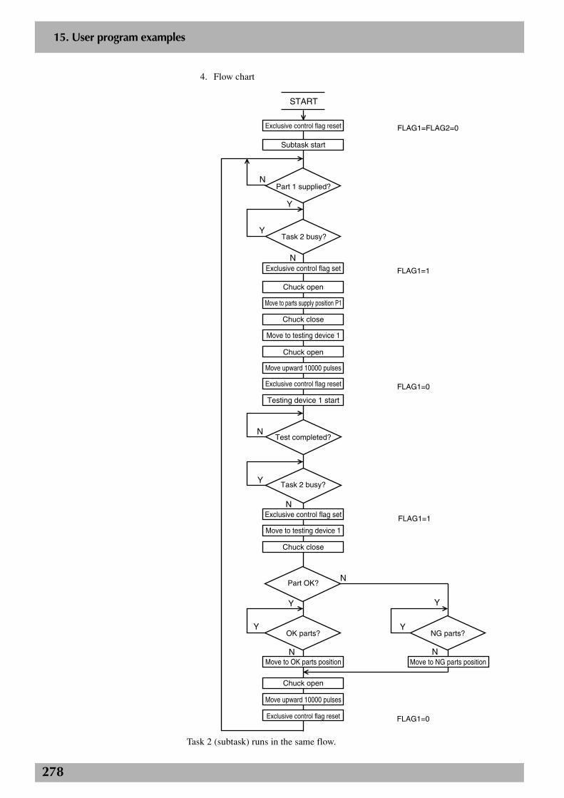
278
2
15. User program examples
4. Flow chart
Task 2 busy?
Exclusive control flag set
Task 2 busy?
START
Exclusive control flag reset
Subtask start
Part 1 supplied?
Chuck open
Move to parts supply position P1
Chuck close
Move to testing device 1
Chuck open
Move upward 10000 pulses
Exclusive control flag reset
Testing device 1 start
Test completed?
Exclusive control flag set
Move to testing device 1
Chuck close
Part OK?
OK parts? NG parts?
Move to OK parts position
Chuck open
Move upward 10000 pulses
Exclusive control flag reset
FLAG1=FLAG2=0
Move to NG parts position
FLAG1=0
FLAG1=1
FLAG1=0
FLAG1=1
N
Y
Y
N
Y
N
N
N
Y
Y
Y
Y
N N
Task 2 (subtask) runs in the same flow.
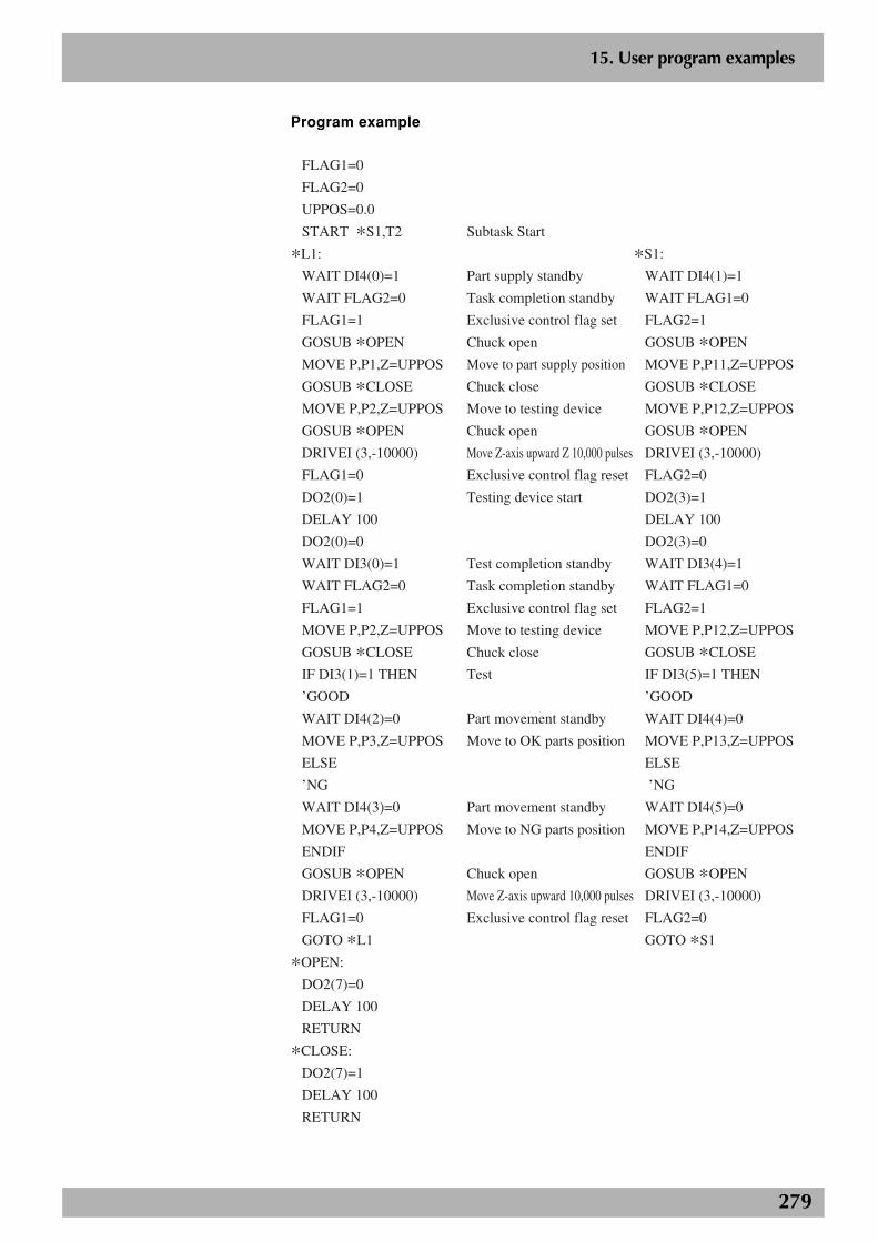
279
2
15. User program examples
Program example
FLAG1=0
FLAG2=0
UPPOS=0.0
START *S1,T2
*L1:
WAIT DI4(0)=1
WAIT FLAG2=0
FLAG1=1
GOSUB *OPEN
MOVE P,P1,Z=UPPOS
GOSUB *CLOSE
MOVE P,P2,Z=UPPOS
GOSUB *OPEN
DRIVEI (3,-10000)
FLAG1=0
DO2(0)=1
DELAY 100
DO2(0)=0
WAIT DI3(0)=1
WAIT FLAG2=0
FLAG1=1
MOVE P,P2,Z=UPPOS
GOSUB *CLOSE
IF DI3(1)=1 THEN
’GOOD
WAIT DI4(2)=0
MOVE P,P3,Z=UPPOS
ELSE
’NG
WAIT DI4(3)=0
MOVE P,P4,Z=UPPOS
ENDIF
GOSUB *OPEN
DRIVEI (3,-10000)
FLAG1=0
GOTO *L1
*OPEN:
DO2(7)=0
DELAY 100
RETURN
*CLOSE:
DO2(7)=1
DELAY 100
RETURN
Subtask Start
Part supply standby
Task completion standby
Exclusive control flag set
Chuck open
Move to part supply position
Chuck close
Move to testing device
Chuck open
Move Z-axis upward Z 10,000 pulses
Exclusive control flag reset
Testing device start
Test completion standby
Task completion standby
Exclusive control flag set
Move to testing device
Chuck close
Test
Part movement standby
Move to OK parts position
Part movement standby
Move to NG parts position
Chuck open
Move Z-axis upward 10,000 pulses
Exclusive control flag reset
*S1:
WAIT DI4(1)=1
WAIT FLAG1=0
FLAG2=1
GOSUB *OPEN
MOVE P,P11,Z=UPPOS
GOSUB *CLOSE
MOVE P,P12,Z=UPPOS
GOSUB *OPEN
DRIVEI (3,-10000)
FLAG2=0
DO2(3)=1
DELAY 100
DO2(3)=0
WAIT DI3(4)=1
WAIT FLAG1=0
FLAG2=1
MOVE P,P12,Z=UPPOS
GOSUB *CLOSE
IF DI3(5)=1 THEN
’GOOD
WAIT DI4(4)=0
MOVE P,P13,Z=UPPOS
ELSE
’NG
WAIT DI4(5)=0
MOVE P,P14,Z=UPPOS
ENDIF
GOSUB *OPEN
DRIVEI (3,-10000)
FLAG2=0
GOTO *S1

280
2
15. User program examples
15.2.5 Sealing
OverviewThis section shows an example of the parts sealing operation.
P0 P1
P2
P3
P4P5
P6 P7
10mm
20mm
Precondition1. I/O signal
DO(20) Valve open/close = 1: open, =0: close
2. Set P0 - P7 by teaching.
Program exampleMOVE P,P0,Z=0SPEED 40PATH SET Start of path setting
Path setting(Robot does not operate.)
PATH L,P1,DO(20)[email protected] Start of coating at 10 mm positionPATH L,P2PATH C,P3,P4PATH L,P5PATH L,P6,S=30PATH L,P7,DO(20)[email protected] End of coating at 20 mm positionPATH END End of path settingPATH START Execute PATH motion (Robot starts from P0 and stops at P7.)HALT
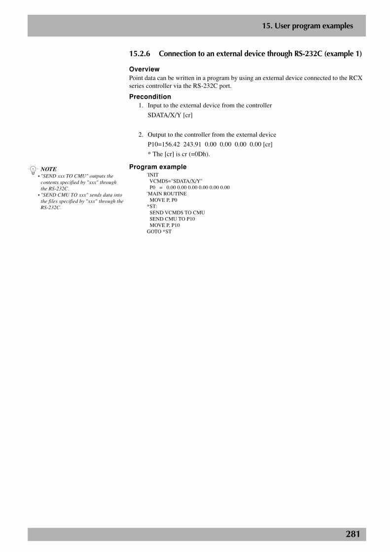
281
2
15. User program examples
15.2.6 Connection to an external device through RS-232C (example 1)
OverviewPoint data can be written in a program by using an external device connected to the RCXseries controller via the RS-232C port.
Precondition1. Input to the external device from the controller
SDATA/X/Y [cr]
2. Output to the controller from the external device
P10=156.42 243.91 0.00 0.00 0.00 0.00 [cr]
* The [cr] is cr (=0Dh).
Program example'INIT VCMD$="SDATA/X/Y" P0 = 0.00 0.00 0.00 0.00 0.00 0.00'MAIN ROUTINE MOVE P, P0*ST: SEND VCMD$ TO CMU SEND CMU TO P10 MOVE P, P10GOTO *ST
n NOTE• "SEND xxx TO CMU" outputs the
contents specified by "xxx" throughthe RS-232C.
• "SEND CMU TO xxx" sends data intothe files specified by "xxx" through theRS-232C.
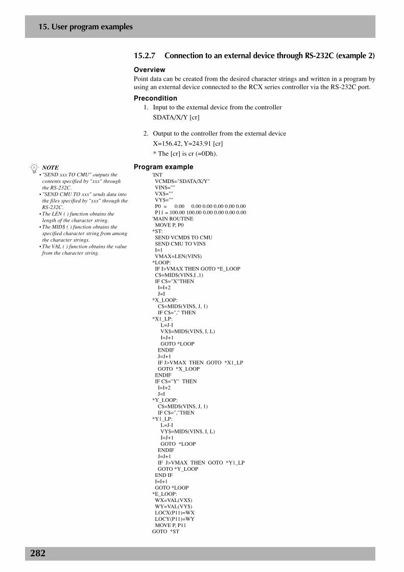
282
2
15. User program examples
15.2.7 Connection to an external device through RS-232C (example 2)
OverviewPoint data can be created from the desired character strings and written in a program byusing an external device connected to the RCX series controller via the RS-232C port.
Precondition1. Input to the external device from the controller
SDATA/X/Y [cr]
2. Output to the controller from the external device
X=156.42, Y=243.91 [cr]
* The [cr] is cr (=0Dh).
Program example'INT VCMD$="SDATA/X/Y" VIN$="" VX$="" VY$="" P0 = 0.00 0.00 0.00 0.00 0.00 0.00 P11 = 100.00 100.00 0.00 0.00 0.00 0.00'MAIN ROUTINE MOVE P, P0*ST: SEND VCMD$ TO CMU SEND CMU TO VIN$ I=1 VMAX=LEN(VIN$)*LOOP: IF I>VMAX THEN GOTO *E_LOOP C$=MID$(VIN$,I ,1) IF C$="X"THEN I=I+2 J=I*X_LOOP: C$=MID$(VIN$, J, 1) IF C$="," THEN*X1_LP: L=J-I VX$=MID$(VIN$, I, L) I=J+1 GOTO *LOOP ENDIF J=J+1 IF J>VMAX THEN GOTO *X1_LP GOTO *X_LOOP ENDIF IF C$="Y" THEN I=I+2 J=I*Y_LOOP: C$=MID$(VIN$, J, 1) IF C$=","THEN*Y1_LP: L=J-I VY$=MID$(VIN$, I, L) I=J+1 GOTO *LOOP ENDIF J=J+1 IF J>VMAX THEN GOTO *Y1_LP GOTO *Y_LOOP END IF I=I+1 GOTO *LOOP*E_LOOP: WX=VAL(VX$) WY=VAL(VY$) LOCX(P11)=WX LOCY(P11)=WY MOVE P, P11GOTO *ST
n NOTE• "SEND xxx TO CMU" outputs the
contents specified by "xxx" throughthe RS-232C.
• "SEND CMU TO xxx" sends data intothe files specified by "xxx" through theRS-232C.
• The LEN ( ) function obtains thelength of the character string.
• The MID$ ( ) function obtains thespecified character string from amongthe character strings.
• The VAL ( ) function obtains the valuefrom the character string.
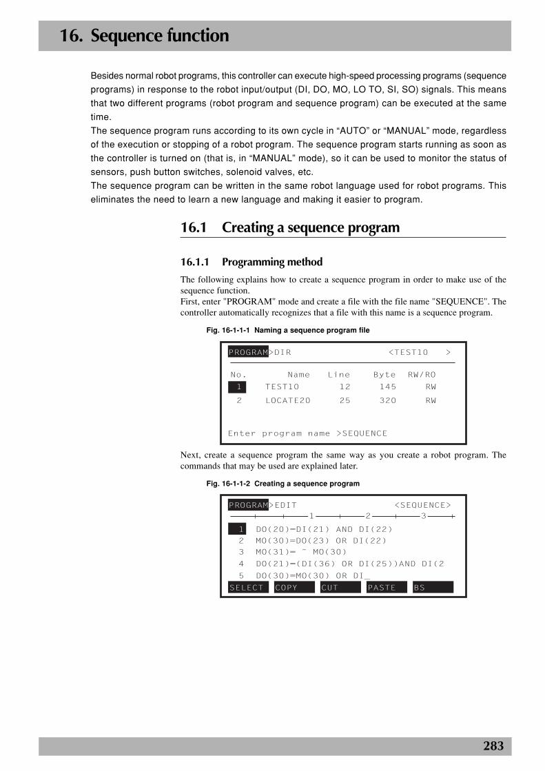
283
16. Sequence function
Besides normal robot programs, this controller can execute high-speed processing programs (sequence
programs) in response to the robot input/output (DI, DO, MO, LO TO, SI, SO) signals. This means
that two different programs (robot program and sequence program) can be executed at the same
time.
The sequence program runs according to its own cycle in “AUTO” or “MANUAL” mode, regardless
of the execution or stopping of a robot program. The sequence program starts running as soon as
the controller is turned on (that is, in “MANUAL” mode), so it can be used to monitor the status of
sensors, push button switches, solenoid valves, etc.
The sequence program can be written in the same robot language used for robot programs. This
eliminates the need to learn a new language and making it easier to program.
16.1 Creating a sequence program
16.1.1 Programming method
The following explains how to create a sequence program in order to make use of thesequence function.First, enter "PROGRAM" mode and create a file with the file name "SEQUENCE". Thecontroller automatically recognizes that a file with this name is a sequence program.
Fig. 16-1-1-1 Naming a sequence program file
PROGRAM>DIR <TEST10 >
No. Name Line Byte RW/RO
Enter program name >SEQUENCE
1 TEST10 12 145 RW
2 LOCATE20 25 320 RW
Next, create a sequence program the same way as you create a robot program. Thecommands that may be used are explained later.
Fig. 16-1-1-2 Creating a sequence program
PROGRAM>EDIT <SEQUENCE>
1 DO(20)=DI(21) AND DI(22)
2 MO(30)=DO(23) OR DI(22)
3 MO(31)= ˜ MO(30)
4 DO(21)=(DI(36) OR DI(25))AND DI(2
5 DO(30)=MO(30) OR DI_
SELECT COPY CUT PASTE BS
321
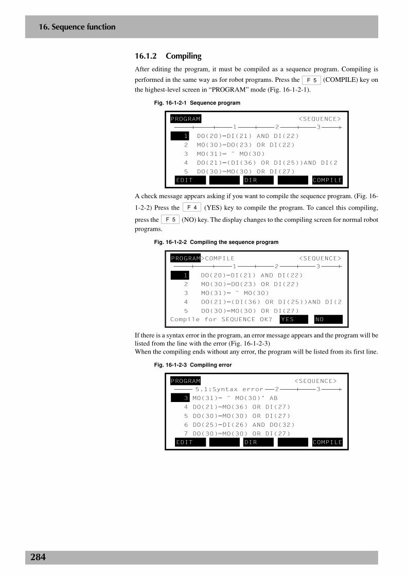
284
2
16. Sequence function
16.1.2 Compiling
After editing the program, it must be compiled as a sequence program. Compiling is
performed in the same way as for robot programs. Press the F 5 (COMPILE) key on
the highest-level screen in “PROGRAM” mode (Fig. 16-1-2-1).
Fig. 16-1-2-1 Sequence program
PROGRAM <SEQUENCE>
1 DO(20)=DI(21) AND DI(22)
2 MO(30)=DO(23) OR DI(22)
3 MO(31)= ˜ MO(30)
4 DO(21)=(DI(36) OR DI(25))AND DI(2
5 DO(30)=MO(30) OR DI(27)
EDIT DIR COMPILE
321
A check message appears asking if you want to compile the sequence program. (Fig. 16-
1-2-2) Press the F 4 (YES) key to compile the program. To cancel this compiling,
press the F 5 (NO) key. The display changes to the compiling screen for normal robotprograms.
Fig. 16-1-2-2 Compiling the sequence program
PROGRAM>COMPILE <SEQUENCE>
1 DO(20)=DI(21) AND DI(22)
2 MO(30)=DO(23) OR DI(22)
3 MO(31)= ˜ MO(30)
4 DO(21)=(DI(36) OR DI(25))AND DI(2
5 DO(30)=MO(30) OR DI(27)
Compile for SEQUENCE OK? YES NO
321
If there is a syntax error in the program, an error message appears and the program will belisted from the line with the error (Fig. 16-1-2-3)When the compiling ends without any error, the program will be listed from its first line.
Fig. 16-1-2-3 Compiling error
PROGRAM <SEQUENCE>
3 MO(31)= ˜ MO(30)’ AB
4 DO(21)=MO(36) OR DI(27)
5 DO(30)=MO(30) OR DI(27)
6 DO(25)=DI(26) AND DO(32)
7 DO(30)=MO(30) OR DI(27)
EDIT DIR COMPILE
325.1:Syntax error

285
2
16. Sequence function
When you display the directory after the compiling the sequence program, a letter “s”appears to the left of the program name “SEQUENCE”. This means that the sequenceprogram has been compiled successfully and is ready for use (Fig. 16-1-2-4).
Fig. 16-1-2-4 Sequence execution program after compiling
PROGRAM>DIR <TEST10 >
No. Name Line Byte RW/RO
1 TEST10 12 145 RW
2 LOCATE20 25 320 RW
3 s SEQUENCE 8 141 RW
NEW I INFO
16.2 Executing a sequence programThe following conditions must be satisfied to execute a sequence program. If any of theseconditions is not met, the sequence program cannot be executed.
1. The sequence execution program has been created by compiling.
2. The sequence function is enabled in “UTILITY” mode.
3. The external sequence control input (DI10) contact is closed.
4. The current operation mode is “MANUAL” or “AUTO”.
When all of the above conditions are met, the sequence program can now be executed.While the program is running, the letter “s” will appear at the left end of the second lineof the screen. (Fig. 16-2-1)
Fig. 16-2-1 Sequence program execution in progress
MANUAL 50% [MG] [S0H0J]S
Current position
M1= 0 M2= 0 *M3= 0
*M4 0
POINT PALLET VEL+ VEL-
c CAUTIONThe sequence execution program iserased and the letter “s” disappears inthe following cases. In these cases thesequence function cannot be used in“UTILITY” mode.
1. When the sequence program waserased
2. When the sequence program wasedited
3. When normal robot programcompiling was performed for thesequence program
4. Program data was initialized.5. A “Sequence object check sum” error
occurred.
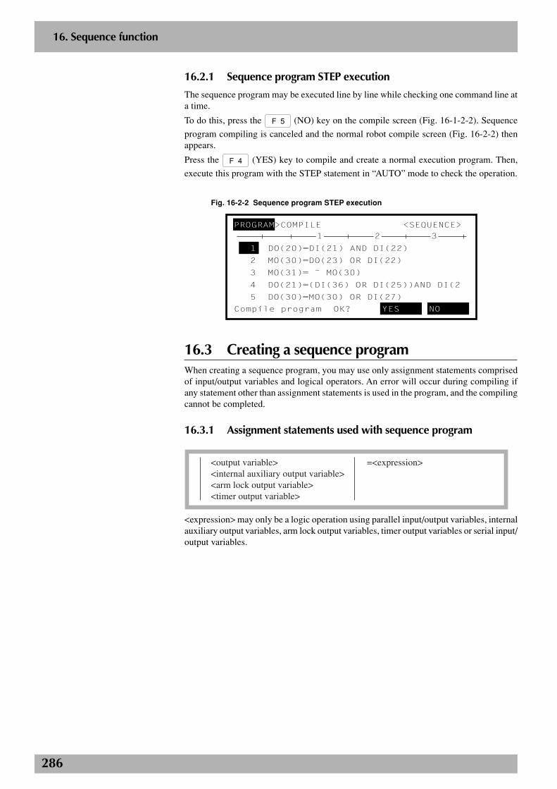
286
2
16. Sequence function
16.2.1 Sequence program STEP execution
The sequence program may be executed line by line while checking one command line ata time.
To do this, press the F 5 (NO) key on the compile screen (Fig. 16-1-2-2). Sequence
program compiling is canceled and the normal robot compile screen (Fig. 16-2-2) thenappears.
Press the F 4 (YES) key to compile and create a normal execution program. Then,
execute this program with the STEP statement in “AUTO” mode to check the operation.
Fig. 16-2-2 Sequence program STEP execution
Compile program OK? YES NO
PROGRAM>COMPILE <SEQUENCE>
1 DO(20)=DI(21) AND DI(22)
2 MO(30)=DO(23) OR DI(22)
3 MO(31)= ˜ MO(30)
4 DO(21)=(DI(36) OR DI(25))AND DI(2
5 DO(30)=MO(30) OR DI(27)
321
16.3 Creating a sequence programWhen creating a sequence program, you may use only assignment statements comprisedof input/output variables and logical operators. An error will occur during compiling ifany statement other than assignment statements is used in the program, and the compilingcannot be completed.
16.3.1 Assignment statements used with sequence program
<output variable> =<expression><internal auxiliary output variable><arm lock output variable><timer output variable>
<expression> may only be a logic operation using parallel input/output variables, internalauxiliary output variables, arm lock output variables, timer output variables or serial input/output variables.
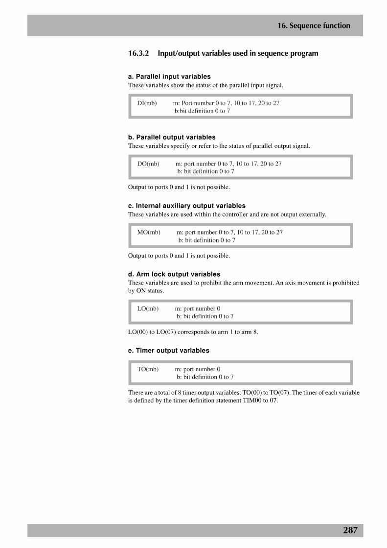
287
2
16. Sequence function
16.3.2 Input/output variables used in sequence program
a. Parallel input variablesThese variables show the status of the parallel input signal.
DI(mb) m: Port number 0 to 7, 10 to 17, 20 to 27 b:bit definition 0 to 7
b. Parallel output variablesThese variables specify or refer to the status of parallel output signal.
DO(mb) m: port number 0 to 7, 10 to 17, 20 to 27b: bit definition 0 to 7
Output to ports 0 and 1 is not possible.
c. Internal auxiliary output variablesThese variables are used within the controller and are not output externally.
MO(mb) m: port number 0 to 7, 10 to 17, 20 to 27b: bit definition 0 to 7
Output to ports 0 and 1 is not possible.
d. Arm lock output variablesThese variables are used to prohibit the arm movement. An axis movement is prohibitedby ON status.
LO(mb) m: port number 0 b: bit definition 0 to 7
LO(00) to LO(07) corresponds to arm 1 to arm 8.
e. Timer output variables
TO(mb) m: port number 0 b: bit definition 0 to 7
There are a total of 8 timer output variables: TO(00) to TO(07). The timer of each variableis defined by the timer definition statement TIM00 to 07.
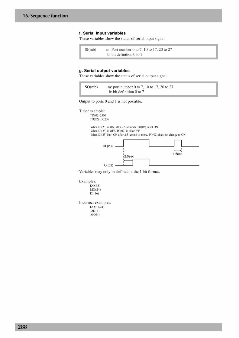
288
2
16. Sequence function
f. Serial input variablesThese variables show the status of serial input signal.
SI(mb) m: Port number 0 to 7, 10 to 17, 20 to 27b: bit definition 0 to 7
g. Serial output variablesThese variables show the status of serial output signal.
SO(mb) m: port number 0 to 7, 10 to 17, 20 to 27b: bit definition 0 to 7
Output to ports 0 and 1 is not possible.
Timer example:TIM02=2500TO(02)=DI(23)
When DI(23) is ON, after 2.5 seconds, TO(02) is set ON.When DI(23) is OFF, TO(02) is also OFF.When DI(23) isn’t ON after 2.5 second or more, TO(02) does not change to ON.
DI (23)
2.5sec
TO (02)
1.6sec
Variables may only be defined in the 1 bit format.
Examples:DO(35)MO(24)DI(16)
Incorrect examples:DO(37,24)DI3(4)MO3()
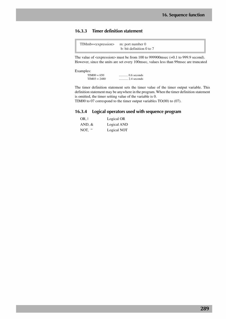
289
2
16. Sequence function
16.3.3 Timer definition statement
TIMmb=<expression> m: port number 0 b: bit definition 0 to 7
The value of <expression> must be from 100 to 999900msec (=0.1 to 999.9 second).However, since the units are set every 100msec, values less than 99msec are truncated
Examples:TIM00 = 650 ............ 0.6 secondsTIM03 = 2480 ............ 2.4 seconds
The timer definition statement sets the timer value of the timer output variable. Thisdefinition statement may be anywhere in the program. When the timer definition statementis omitted, the timer setting value of the variable is 0.TIM00 to 07 correspond to the timer output variables TO(00) to (07).
16.3.4 Logical operators used with sequence program
OR, | Logical OR
AND, & Logical AND
NOT, ~ Logical NOT
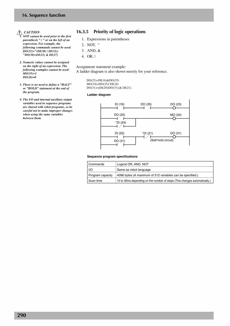
290
2
16. Sequence function
c CAUTION1. NOT cannot be used prior to the first
parenthesis “ ( “ or on the left of anexpression. For example, thefollowing commands cannot be used.DO(21)=~(DI(30) | DI(32))~DO(30)=DI(22) & DI(27)
2. Numeric values cannot be assignedon the right of an expression. Thefollowing examples cannot be used:MO(35)=1DO(26)=0
3. There is no need to define a ”HALT”or ”HOLD” statement at the end ofthe program.
4. The I/O and internal auxiliary outputvariables used in sequence programsare shared with robot programs, so becareful not to make improper changeswhen using the same variablesbetween them.
16.3.5 Priority of logic operations
1. Expressions in parentheses
2. NOT, ~
3. AND, &
4. OR, |
Assignment statement example:A ladder diagram is also shown merely for your reference.
DO(23)=DI(16)&DO(35)MO(34)=DO(25)| DI(24)DO(31)=(DI(20)|DO(31))& DI(21)
Ladder diagram
DI (16)
DO (25)
~DI (24)
DI (20)
DO (31)
DO (35)
~DI (21)
DO (23)
MO (34)
DO (31)
(Self-hold circuit)
Sequence program specifications
Commands
I/O
Program capacity
Scan time
Logical OR, AND, NOT
Same as robot language
4096 bytes (A maximum of 512 variables can be specified.)
10 to 30ms depending on the number of steps (This changes automatically.)
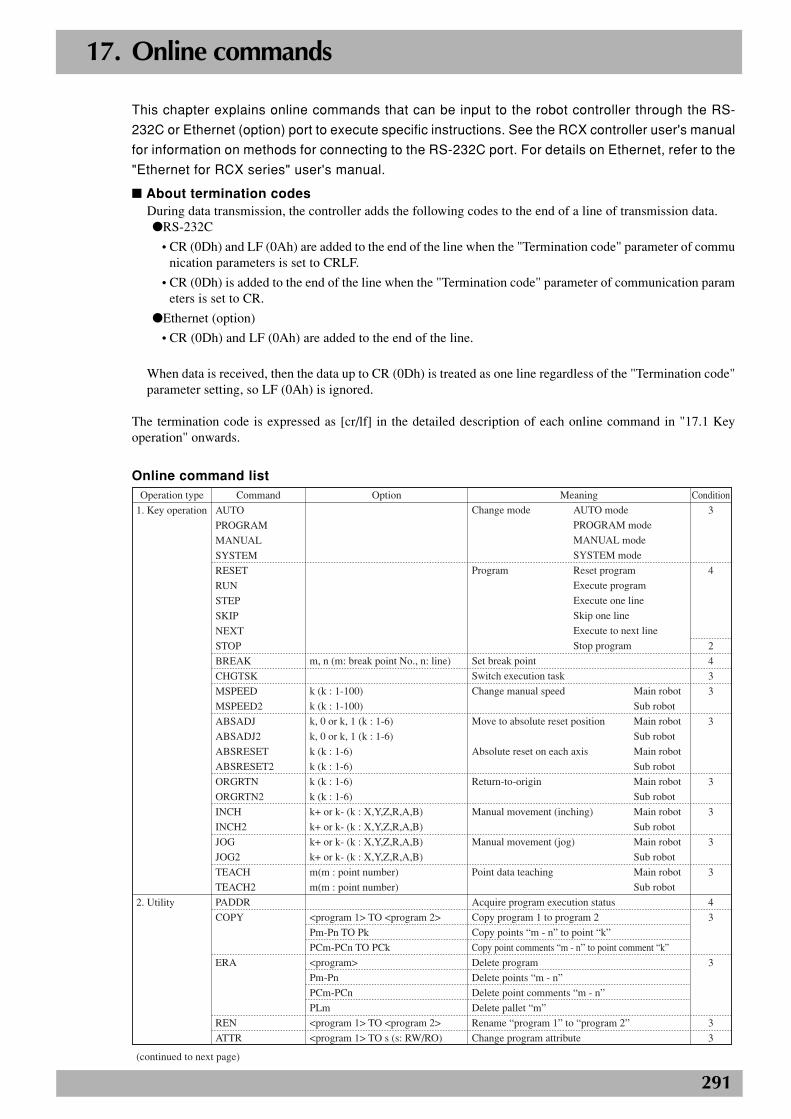
291
17. Online commands
This chapter explains online commands that can be input to the robot controller through the RS-
232C or Ethernet (option) port to execute specific instructions. See the RCX controller user's manual
for information on methods for connecting to the RS-232C port. For details on Ethernet, refer to the
"Ethernet for RCX series" user's manual.
■ About termination codesDuring data transmission, the controller adds the following codes to the end of a line of transmission data.●RS-232C
• CR (0Dh) and LF (0Ah) are added to the end of the line when the "Termination code" parameter of communication parameters is set to CRLF.
• CR (0Dh) is added to the end of the line when the "Termination code" parameter of communication parameters is set to CR.
●Ethernet (option)
• CR (0Dh) and LF (0Ah) are added to the end of the line.
When data is received, then the data up to CR (0Dh) is treated as one line regardless of the "Termination code"parameter setting, so LF (0Ah) is ignored.
The termination code is expressed as [cr/lf] in the detailed description of each online command in "17.1 Keyoperation" onwards.
Online command list
1. Key operation
2. Utility
AUTO
PROGRAM
MANUAL
SYSTEM
RESET
RUN
STEP
SKIP
NEXT
STOP
BREAK
CHGTSK
MSPEED
MSPEED2
ABSADJ
ABSADJ2
ABSRESET
ABSRESET2
ORGRTN
ORGRTN2
INCH
INCH2
JOG
JOG2
TEACH
TEACH2
PADDR
COPY
ERA
REN
ATTR
m, n (m: break point No., n: line)
k (k : 1-100)
k (k : 1-100)
k, 0 or k, 1 (k : 1-6)
k, 0 or k, 1 (k : 1-6)
k (k : 1-6)
k (k : 1-6)
k (k : 1-6)
k (k : 1-6)
k+ or k- (k : X,Y,Z,R,A,B)
k+ or k- (k : X,Y,Z,R,A,B)
k+ or k- (k : X,Y,Z,R,A,B)
k+ or k- (k : X,Y,Z,R,A,B)
m(m : point number)
m(m : point number)
<program 1> TO <program 2>
Pm-Pn TO Pk
PCm-PCn TO PCk
<program>
Pm-Pn
PCm-PCn
PLm
<program 1> TO <program 2>
<program 1> TO s (s: RW/RO)
Change mode AUTO mode
PROGRAM mode
MANUAL mode
SYSTEM mode
Program Reset program
Execute program
Execute one line
Skip one line
Execute to next line
Stop program
Set break point
Switch execution task
Change manual speed Main robot
Sub robot
Move to absolute reset position Main robot
Sub robot
Absolute reset on each axis Main robot
Sub robot
Return-to-origin Main robot
Sub robot
Manual movement (inching) Main robot
Sub robot
Manual movement (jog) Main robot
Sub robot
Point data teaching Main robot
Sub robot
Acquire program execution status
Copy program 1 to program 2
Copy points “m - n” to point “k”
Copy point comments “m - n” to point comment “k”
Delete program
Delete points “m - n”
Delete point comments “m - n”
Delete pallet “m”
Rename “program 1” to “program 2”
Change program attribute
Meaning ConditionCommandOperation type Option
3
4
2
4
3
3
3
3
3
3
3
4
3
3
3
3
(continued to next page)
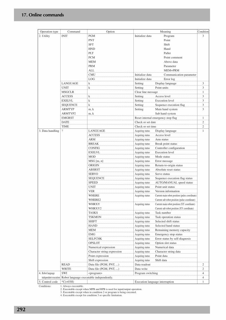
292
2
17. Online commands
2. Utility
3. Data handling
4. Robot language
independent execution
5. Control code
INIT
LANGUAGE
UNIT
MSGCLR
ACCESS
EXELVL
SEQUENCE
ARMTYP
ARMTYP2
EMGRST
DATE
TIME
?
READ
WRITE
SWI
^C(=03H)
PGM
PNT
SFT
HND
PLT
PCM
MEM
PRM
ALL
CMU
LOG
k
k
k
k
k
m, k
m, k
LANGUAGE
ACCESS
ARM
BREAK
CONFIG
EXELVL
MOD
MSG [m, n]
ORIGIN
ABSRST
SERVO
SEQUENCE
SPEED
UNIT
VER
WHERE
WHERE2
WHRXY
WHRXY2
TASKS
TSKMON
SHIFT
HAND
MEM
EMG
SELFCHK
OPSLOT
Numerical expression
Character string expression
Point expression
Shift expression
Data file (PGM, PNT, ...)
Data file (PGM, PNT, ...)
<program>
Initialize data Program
Point
Shift
Hand
Pallet
Point comment
Above data
Parameter
MEM+PRM
Initialize data Communication parameter
Initialize data Error log
Setting Display language
Setting Point units
Clear line message
Setting Access level
Setting Execution level
Setting Sequence execution flag
Setting Main hand system
Sub hand system
Reset internal emergency stop flag
Check or set date
Check or set time
Acquiring status Display language
Acquiring status Access level
Acquiring status Arm status
Acquiring status Break point status
Acquiring status Controller configuration
Acquiring status Execution level
Acquiring status Mode status
Acquiring status Error message
Acquiring status Return-to-origin status
Acquiring status Absolute reset status
Acquiring status Servo status
Acquiring status Sequence execution flag status
Acquiring status AUTO/MANUAL speed status
Acquiring status Point unit status
Acquiring status Version information
Acquiring status Current main robot position (pulse coordinate)
Current sub robot position (pulse coordinate)
Acquiring status Current main robot position (XY coordinate)
Current sub robot position (XY coordinate)
Acquiring status Task number
Acquiring status Task operation status
Acquiring status Selected shift status
Acquiring status Selected hand status
Acquiring status Remaining memory capacity
Acquiring status Emergency stop status
Acquiring status Error status by self-diagnosis
Acquiring status Option slot status
Acquiring status Numerical data
Acquiring status Character string data
Acquiring status Point data
Acquiring status Shift data
Meaning ConditionCommandOperation type Option
3
3
3
1
3
3
3
3
1
2
2
1
2
2
4
4
1
Robot language executable independently.
Conditions: 1. Always executable. 2. Executable except when MPB and RPB is used for input/output operation. 3. Executable except when in condition 2 or program is being executed. 4. Executable except for condition 3 or specific limitation.
Data readout
Data write
Program switching
Execution language interruption
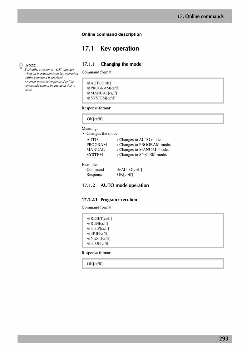
293
2
17. Online commands
Online command description
17.1 Key operation
17.1.1 Changing the mode
Command format:
@AUTO[cr/lf]@PROGRAM[cr/lf]@MANUAL[cr/lf]@SYSTEM[cr/lf]
Response format:
OK[cr/lf]
Meaning:• Changes the mode.
AUTO : Changes to AUTO mode.PROGRAM : Changes to PROGRAM mode.MANUAL : Changes to MANUAL mode.SYSTEM : Changes to SYSTEM mode.
Example:Command @AUTO[cr/lf]Response OK[cr/lf]
17.1.2 AUTO mode operation
17.1.2.1 Program execution
Command format:
@RESET[cr/lf]@RUN[cr/lf]@STEP[cr/lf]@SKIP[cr/lf]@NEXT[cr/lf]@STOP[cr/lf]
Response format:
OK[cr/lf]
n NOTEBasically, a response “OK” appearswhen an instruction from key operationonline command is received.An error message responds if onlinecommands cannot be executed due toerror.
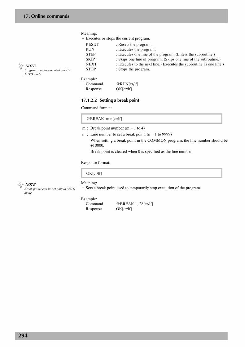
294
2
17. Online commands
n NOTEPrograms can be executed only inAUTO mode.
Meaning:• Executes or stops the current program.
RESET : Resets the program.RUN : Executes the program.STEP : Executes one line of the program. (Enters the subroutine.)SKIP : Skips one line of program. (Skips one line of the subroutine.)NEXT : Executes to the next line. (Executes the subroutine as one line.)STOP : Stops the program.
Example:Command @RUN[cr/lf]Response OK[cr/lf]
17.1.2.2 Setting a break point
Command format:
@BREAK m,n[cr/lf]
m : Break point number (m = 1 to 4)
n : Line number to set a break point. (n = 1 to 9999)
When setting a break point in the COMMON program, the line number should be+10000.
Break point is cleared when 0 is specified as the line number.
Response format:
OK[cr/lf]
Meaning:• Sets a break point used to temporarily stop execution of the program.
Example:Command @BREAK 1, 28[cr/lf]Response OK[cr/lf]
n NOTEBreak points can be set only in AUTOmode.
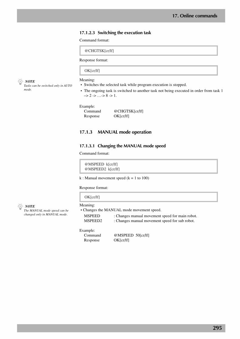
295
2
17. Online commands
17.1.2.3 Switching the execution task
Command format:
@CHGTSK[cr/lf]
Response format:
OK[cr/lf]
Meaning:• Switches the selected task while program execution is stopped.
• The ongoing task is switched to another task not being executed in order from task 1–> 2 -> …-> 8 -> 1.
Example:Command @CHGTSK[cr/lf]Response OK[cr/lf]
17.1.3 MANUAL mode operation
17.1.3.1 Changing the MANUAL mode speed
Command format:
@MSPEED k[cr/lf]@MSPEED2 k[cr/lf]
k : Manual movement speed (k = 1 to 100)
Response format:
OK[cr/lf]
Meaning:• Changes the MANUAL mode movement speed.
MSPEED : Changes manual movement speed for main robot.MSPEED2 : Changes manual movement speed for sub robot.
Example:Command @MSPEED 50[cr/lf]Response OK[cr/lf]
n NOTETasks can be switched only in AUTOmode.
n NOTEThe MANUAL mode speed can bechanged only in MANUAL mode.
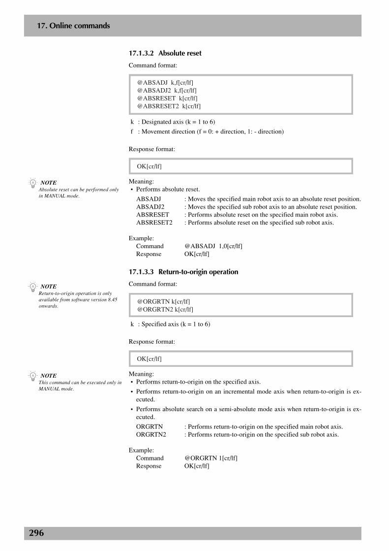
296
2
17. Online commands
17.1.3.2 Absolute reset
Command format:
@ABSADJ k,f[cr/lf]@ABSADJ2 k,f[cr/lf]@ABSRESET k[cr/lf]@ABSRESET2 k[cr/lf]
k : Designated axis (k = 1 to 6)
f : Movement direction (f = 0: + direction, 1: - direction)
Response format:
OK[cr/lf]
Meaning:• Performs absolute reset.
ABSADJ : Moves the specified main robot axis to an absolute reset position.ABSADJ2 : Moves the specified sub robot axis to an absolute reset position.ABSRESET : Performs absolute reset on the specified main robot axis.ABSRESET2 : Performs absolute reset on the specified sub robot axis.
Example:Command @ABSADJ 1,0[cr/lf]Response OK[cr/lf]
17.1.3.3 Return-to-origin operation
Command format:
@ORGRTN k[cr/lf]@ORGRTN2 k[cr/lf]
k : Specified axis (k = 1 to 6)
Response format:
OK[cr/lf]
Meaning:• Performs return-to-origin on the specified axis.
• Performs return-to-origin on an incremental mode axis when return-to-origin is ex-ecuted.
• Performs absolute search on a semi-absolute mode axis when return-to-origin is ex-ecuted.
ORGRTN : Performs return-to-origin on the specified main robot axis.ORGRTN2 : Performs return-to-origin on the specified sub robot axis.
Example:Command @ORGRTN 1[cr/lf]Response OK[cr/lf]
n NOTEAbsolute reset can be performed onlyin MANUAL mode.
n NOTEReturn-to-origin operation is onlyavailable from software version 8.45onwards.
n NOTEThis command can be executed only inMANUAL mode.
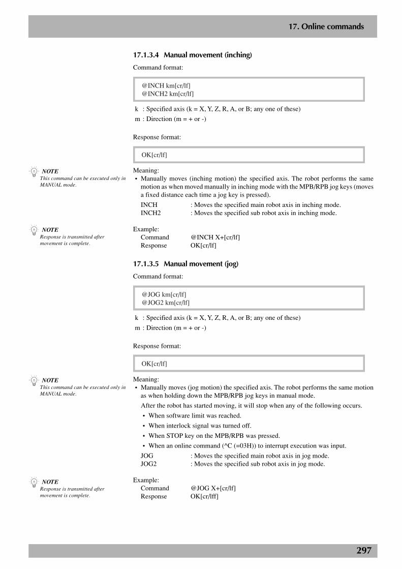
297
2
17. Online commands
17.1.3.4 Manual movement (inching)
Command format:
@INCH km[cr/lf]@INCH2 km[cr/lf]
k : Specified axis (k = X, Y, Z, R, A, or B; any one of these)
m : Direction (m = + or -)
Response format:
OK[cr/lf]
Meaning:• Manually moves (inching motion) the specified axis. The robot performs the same
motion as when moved manually in inching mode with the MPB/RPB jog keys (movesa fixed distance each time a jog key is pressed).
INCH : Moves the specified main robot axis in inching mode.INCH2 : Moves the specified sub robot axis in inching mode.
Example:Command @INCH X+[cr/lf]Response OK[cr/lf]
17.1.3.5 Manual movement (jog)
Command format:
@JOG km[cr/lf]@JOG2 km[cr/lf]
k : Specified axis (k = X, Y, Z, R, A, or B; any one of these)
m : Direction (m = + or -)
Response format:
OK[cr/lf]
Meaning:• Manually moves (jog motion) the specified axis. The robot performs the same motion
as when holding down the MPB/RPB jog keys in manual mode.
After the robot has started moving, it will stop when any of the following occurs.
• When software limit was reached.
• When interlock signal was turned off.
• When STOP key on the MPB/RPB was pressed.
• When an online command (^C (=03H)) to interrupt execution was input.
JOG : Moves the specified main robot axis in jog mode.JOG2 : Moves the specified sub robot axis in jog mode.
Example:Command @JOG X+[cr/lf]Response OK[cr/lff]
n NOTEThis command can be executed only inMANUAL mode.
n NOTEResponse is transmitted aftermovement is complete.
n NOTEThis command can be executed only inMANUAL mode.
n NOTEResponse is transmitted aftermovement is complete.
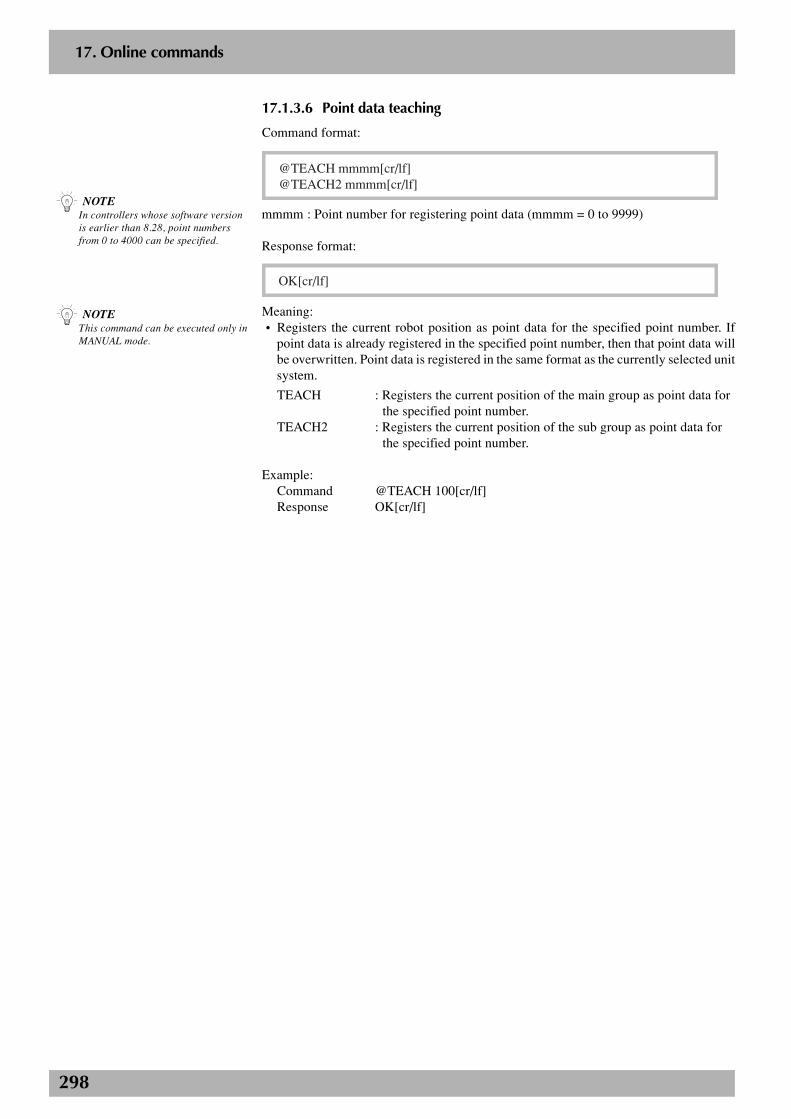
298
2
17. Online commands
17.1.3.6 Point data teaching
Command format:
@TEACH mmmm[cr/lf]@TEACH2 mmmm[cr/lf]
mmmm : Point number for registering point data (mmmm = 0 to 9999)
Response format:
OK[cr/lf]
Meaning:• Registers the current robot position as point data for the specified point number. If
point data is already registered in the specified point number, then that point data willbe overwritten. Point data is registered in the same format as the currently selected unitsystem.
TEACH : Registers the current position of the main group as point data forthe specified point number.
TEACH2 : Registers the current position of the sub group as point data forthe specified point number.
Example:Command @TEACH 100[cr/lf]Response OK[cr/lf]
n NOTEIn controllers whose software versionis earlier than 8.28, point numbersfrom 0 to 4000 can be specified.
n NOTEThis command can be executed only inMANUAL mode.
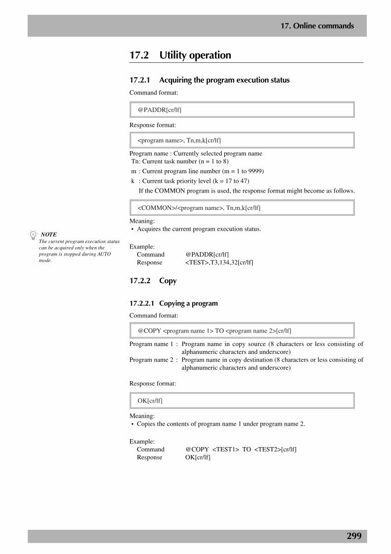
299
2
17. Online commands
17.2 Utility operation
17.2.1 Acquiring the program execution status
Command format:
@PADDR[cr/lf]
Response format:
<program name>, Tn,m,k[cr/lf]
Program name : Currently selected program nameTn: Current task number (n = 1 to 8)
m : Current program line number (m = 1 to 9999)
k : Current task priority level (k = 17 to 47)
If the COMMON program is used, the response format might become as follows.
<COMMON>/<program name>, Tn,m,k[cr/lf]
Meaning:• Acquires the current program execution status.
Example:Command @PADDR[cr/lf]Response <TEST>,T3,134,32[cr/lf]
17.2.2 Copy
17.2.2.1 Copying a program
Command format:
@COPY <program name 1> TO <program name 2>[cr/lf]
Program name 1 : Program name in copy source (8 characters or less consisting ofalphanumeric characters and underscore)
Program name 2 : Program name in copy destination (8 characters or less consisting ofalphanumeric characters and underscore)
Response format:
OK[cr/lf]
Meaning:• Copies the contents of program name 1 under program name 2.
Example:Command @COPY <TEST1> TO <TEST2>[cr/lf]Response OK[cr/lf]
n NOTEThe current program execution statuscan be acquired only when theprogram is stopped during AUTOmode.
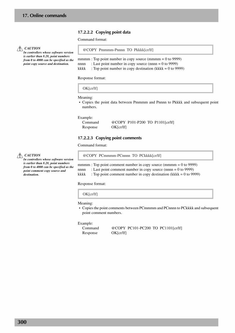
300
2
17. Online commands
17.2.2.2 Copying point data
Command format:
@COPY Pmmmm-Pnnnn TO Pkkkk[cr/lf]
mmmm : Top point number in copy source (mmmm = 0 to 9999)nnnn : Last point number in copy source (nnnn = 0 to 9999)kkkk : Top point number in copy destination (kkkk = 0 to 9999)
Response format:
OK[cr/lf]
Meaning:• Copies the point data between Pmmmm and Pnnnn to Pkkkk and subsequent point
numbers.
Example:Command @COPY P101-P200 TO P1101[cr/lf]Response OK[cr/lf]
17.2.2.3 Copying point comments
Command format:
@COPY PCmmmm-PCnnnn TO PCkkkk[cr/lf]
mmmm : Top point comment number in copy source (mmmm = 0 to 9999)nnnn : Last point comment number in copy source (nnnn = 0 to 9999)kkkk : Top point comment number in copy destination (kkkk = 0 to 9999)
Response format:
OK[cr/lf]
Meaning:• Copies the point comments between PCmmmm and PCnnnn to PCkkkk and subsequent
point comment numbers.
Example:Command @COPY PC101-PC200 TO PC1101[cr/lf]Response OK[cr/lf]
c CAUTIONIn controllers whose software versionis earlier than 8.28, point numbersfrom 0 to 4000 can be specified as thepoint copy source and destination.
c CAUTIONIn controllers whose software versionis earlier than 8.28, point numbersfrom 0 to 4000 can be specified as thepoint comment copy source anddestination.
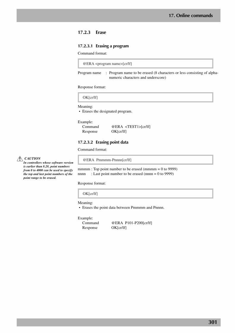
301
2
17. Online commands
17.2.3 Erase
17.2.3.1 Erasing a program
Command format:
@ERA <program name>[cr/lf]
Program name : Program name to be erased (8 characters or less consisting of alpha-numeric characters and underscore)
Response format:
OK[cr/lf]
Meaning:• Erases the designated program.
Example:Command @ERA <TEST1>[cr/lf]Response OK[cr/lf]
17.2.3.2 Erasing point data
Command format:
@ERA Pmmmm-Pnnnn[cr/lf]
mmmm : Top point number to be erased (mmmm = 0 to 9999)nnnn : Last point number to be erased (nnnn = 0 to 9999)
Response format:
OK[cr/lf]
Meaning:• Erases the point data between Pmmmm and Pnnnn.
Example:Command @ERA P101-P200[cr/lf]Response OK[cr/lf]
c CAUTIONIn controllers whose software versionis earlier than 8.28, point numbersfrom 0 to 4000 can be used to specifythe top and last point numbers of thepoint range to be erased.

302
2
17. Online commands
17.2.3.3 Erasing point comments
Command format:
@ERA PCmmmm-PCnnnn[cr/lf]
mmmm : Top point comment number to be erased (mmmm = 0 to 9999)nnnn : Last point comment number to be erased (nnnn = 0 to 9999)
Response format:
OK[cr/lf]
Meaning:• Erases the point comments between PCmmmm and PCnnnn.
Example:Command @ERA PC101-PC200[cr/lf]Response OK[cr/lf]
17.2.3.4 Erasing pallet data
Command format:
@ERA PLm[cr/lf]
m : Pallet number to be erased (m = 0 to 19)
Response format:
OK[cr/lf]
Meaning:• Erases the designated pallet data.
Example:Command @ERA PL1[cr/lf]Response OK[cr/lf]
c CAUTIONIn controllers whose software versionis earlier than 8.28, point numbersfrom 0 to 4000 can be used to specifythe top and last point numbers of thepoint comment range to be erased.
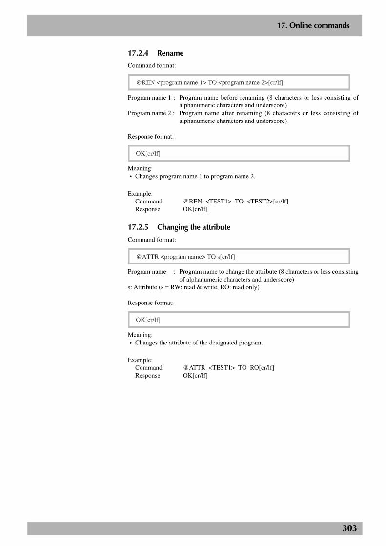
303
2
17. Online commands
17.2.4 Rename
Command format:
@REN <program name 1> TO <program name 2>[cr/lf]
Program name 1 : Program name before renaming (8 characters or less consisting ofalphanumeric characters and underscore)
Program name 2 : Program name after renaming (8 characters or less consisting ofalphanumeric characters and underscore)
Response format:
OK[cr/lf]
Meaning:• Changes program name 1 to program name 2.
Example:Command @REN <TEST1> TO <TEST2>[cr/lf]Response OK[cr/lf]
17.2.5 Changing the attribute
Command format:
@ATTR <program name> TO s[cr/lf]
Program name : Program name to change the attribute (8 characters or less consistingof alphanumeric characters and underscore)
s: Attribute (s = RW: read & write, RO: read only)
Response format:
OK[cr/lf]
Meaning:• Changes the attribute of the designated program.
Example:Command @ATTR <TEST1> TO RO[cr/lf]Response OK[cr/lf]
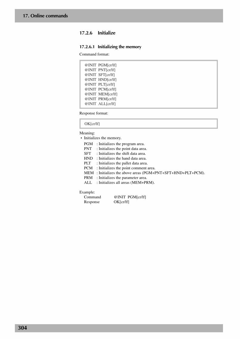
304
2
17. Online commands
17.2.6 Initialize
17.2.6.1 Initializing the memory
Command format:
@INIT PGM[cr/lf]@INIT PNT[cr/lf]@INIT SFT[cr/lf]@INIT HND[cr/lf]@INIT PLT[cr/lf]@INIT PCM[cr/lf]@INIT MEM[cr/lf]@INIT PRM[cr/lf]@INIT ALL[cr/lf]
Response format:
OK[cr/lf]
Meaning:• Initializes the memory.
PGM : Initializes the program area.PNT : Initializes the point data area.SFT : Initializes the shift data area.HND : Initializes the hand data area.PLT : Initializes the pallet data area.PCM : Initializes the point comment area.MEM : Initializes the above areas (PGM+PNT+SFT+HND+PLT+PCM).PRM : Initializes the parameter area.ALL : Initializes all areas (MEM+PRM).
Example:Command @INIT PGM[cr/lf]Response OK[cr/lf]
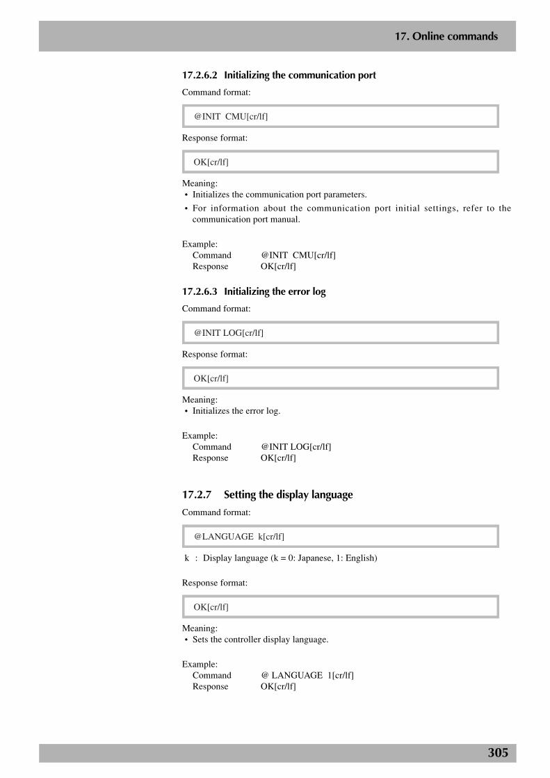
305
2
17. Online commands
17.2.6.2 Initializing the communication port
Command format:
@INIT CMU[cr/lf]
Response format:
OK[cr/lf]
Meaning:• Initializes the communication port parameters.
• For information about the communication port initial settings, refer to thecommunication port manual.
Example:Command @INIT CMU[cr/lf]Response OK[cr/lf]
17.2.6.3 Initializing the error log
Command format:
@INIT LOG[cr/lf]
Response format:
OK[cr/lf]
Meaning:• Initializes the error log.
Example:Command @INIT LOG[cr/lf]Response OK[cr/lf]
17.2.7 Setting the display language
Command format:
@LANGUAGE k[cr/lf]
k : Display language (k = 0: Japanese, 1: English)
Response format:
OK[cr/lf]
Meaning:• Sets the controller display language.
Example:Command @ LANGUAGE 1[cr/lf]Response OK[cr/lf]
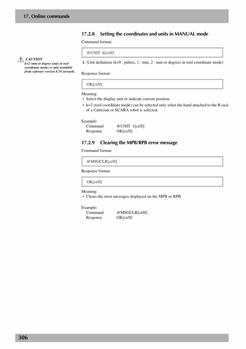
306
2
17. Online commands
17.2.8 Setting the coordinates and units in MANUAL mode
Command format:
@UNIT k[cr/lf]
k :Unit definition (k=0 : pulses, 1 : mm, 2 : mm or degrees in tool coordinate mode)
Response format:
OK[cr/lf]
Meaning:• Select the display unit to indicate current position.
• k=2 (tool coordinate mode) can be selected only when the hand attached to the R-axisof a Cartesian or SCARA robot is selected.
Example:Command @UNIT 1[cr/lf]Response OK[cr/lf]
17.2.9 Clearing the MPB/RPB error message
Command format:
@MSGCLR[cr/lf]
Response format:
OK[cr/lf]
Meaning:• Clears the error messages displayed on the MPB or RPB.
Example:Command @MSGCLR[cr/lf]Response OK[cr/lf]
c CAUTIONk=2 (mm or degree units in toolcoordinate mode) is only availablefrom software version 8.19 onwards.
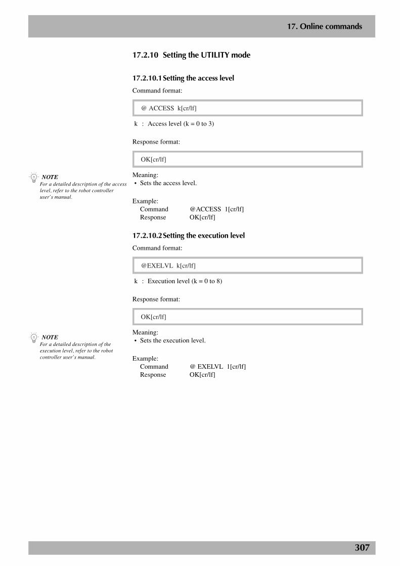
307
2
17. Online commands
17.2.10 Setting the UTILITY mode
17.2.10.1Setting the access level
Command format:
@ ACCESS k[cr/lf]
k : Access level (k = 0 to 3)
Response format:
OK[cr/lf]
Meaning:• Sets the access level.
Example:Command @ACCESS 1[cr/lf]Response OK[cr/lf]
17.2.10.2Setting the execution level
Command format:
@EXELVL k[cr/lf]
k : Execution level (k = 0 to 8)
Response format:
OK[cr/lf]
Meaning:• Sets the execution level.
Example:Command @ EXELVL 1[cr/lf]Response OK[cr/lf]
n NOTEFor a detailed description of the accesslevel, refer to the robot controlleruser’s manual.
n NOTEFor a detailed description of theexecution level, refer to the robotcontroller user’s manual.
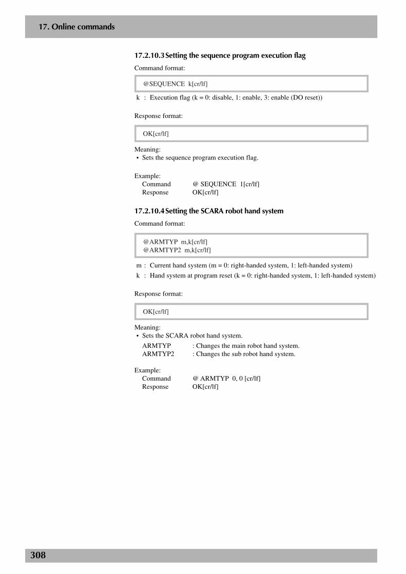
308
2
17. Online commands
17.2.10.3Setting the sequence program execution flag
Command format:
@SEQUENCE k[cr/lf]
k : Execution flag (k = 0: disable, 1: enable, 3: enable (DO reset))
Response format:
OK[cr/lf]
Meaning:• Sets the sequence program execution flag.
Example:Command @ SEQUENCE 1[cr/lf]Response OK[cr/lf]
17.2.10.4Setting the SCARA robot hand system
Command format:
@ARMTYP m,k[cr/lf]@ARMTYP2 m,k[cr/lf]
m : Current hand system (m = 0: right-handed system, 1: left-handed system)
k : Hand system at program reset (k = 0: right-handed system, 1: left-handed system)
Response format:
OK[cr/lf]
Meaning:• Sets the SCARA robot hand system.
ARMTYP : Changes the main robot hand system.ARMTYP2 : Changes the sub robot hand system.
Example:Command @ ARMTYP 0, 0 [cr/lf]Response OK[cr/lf]
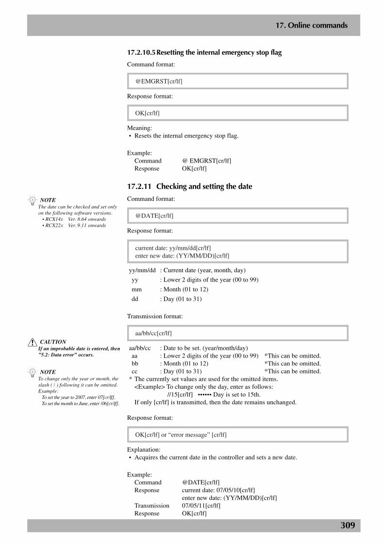
309
2
17. Online commands
17.2.10.5Resetting the internal emergency stop flag
Command format:
@EMGRST[cr/lf]
Response format:
OK[cr/lf]
Meaning:• Resets the internal emergency stop flag.
Example:Command @ EMGRST[cr/lf]Response OK[cr/lf]
17.2.11 Checking and setting the date
Command format:
@DATE[cr/lf]
Response format:
current date: yy/mm/dd[cr/lf]enter new date: (YY/MM/DD)[cr/lf]
yy/mm/dd : Current date (year, month, day)
yy : Lower 2 digits of the year (00 to 99)
mm : Month (01 to 12)
dd : Day (01 to 31)
Transmission format:
aa/bb/cc[cr/lf]
aa/bb/cc : Date to be set. (year/month/day)aa : Lower 2 digits of the year (00 to 99) *This can be omitted.bb : Month (01 to 12) *This can be omitted.cc : Day (01 to 31) *This can be omitted.
* The currently set values are used for the omitted items.<Example> To change only the day, enter as follows:
//15[cr/lf] •••••• Day is set to 15th.If only [cr/lf] is transmitted, then the date remains unchanged.
Response format:
OK[cr/lf] or “error message” [cr/lf]
Explanation:• Acquires the current date in the controller and sets a new date.
Example:Command @DATE[cr/lf]Response current date: 07/05/10[cr/lf]
enter new date: (YY/MM/DD)[cr/lf]Transmission 07/05/11[cr/lf]Response OK[cr/lf]
n NOTEThe date can be checked and set onlyon the following software versions. • RCX14x Ver. 8.64 onwards • RCX22x Ver. 9.11 onwards
c CAUTIONIf an improbable date is entered, then"5.2: Data error" occurs.
n NOTETo change only the year or month, theslash ( / ) following it can be omitted.Example:
To set the year to 2007, enter 07[cr/lf].To set the month to June, enter /06[cr/lf].
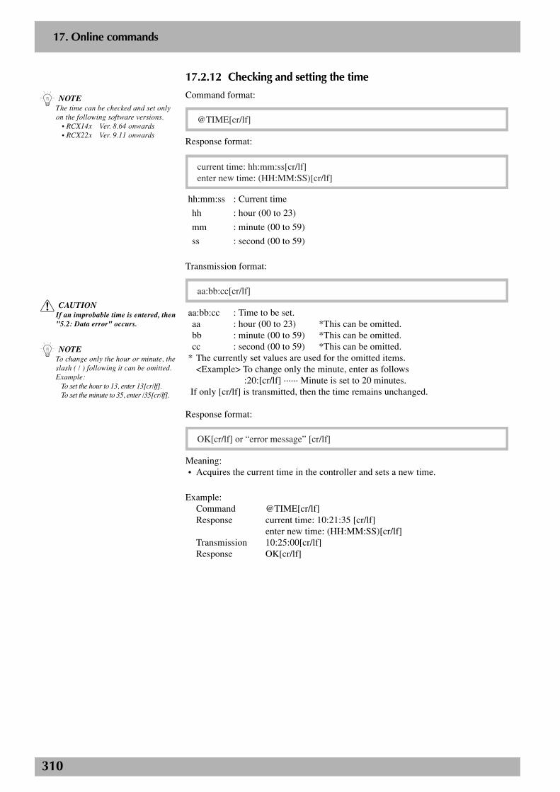
310
2
17. Online commands
17.2.12 Checking and setting the time
Command format:
@TIME[cr/lf]
Response format:
current time: hh:mm:ss[cr/lf]enter new time: (HH:MM:SS)[cr/lf]
hh:mm:ss : Current time
hh : hour (00 to 23)
mm : minute (00 to 59)
ss : second (00 to 59)
Transmission format:
aa:bb:cc[cr/lf]
aa:bb:cc : Time to be set.aa : hour (00 to 23) *This can be omitted.bb : minute (00 to 59) *This can be omitted.cc : second (00 to 59) *This can be omitted.
* The currently set values are used for the omitted items.<Example> To change only the minute, enter as follows
:20:[cr/lf] ······ Minute is set to 20 minutes. If only [cr/lf] is transmitted, then the time remains unchanged.
Response format:
OK[cr/lf] or “error message” [cr/lf]
Meaning:• Acquires the current time in the controller and sets a new time.
Example:Command @TIME[cr/lf]Response current time: 10:21:35 [cr/lf]
enter new time: (HH:MM:SS)[cr/lf]Transmission 10:25:00[cr/lf]Response OK[cr/lf]
n NOTEThe time can be checked and set onlyon the following software versions. • RCX14x Ver. 8.64 onwards • RCX22x Ver. 9.11 onwards
c CAUTIONIf an improbable time is entered, then"5.2: Data error" occurs.
n NOTETo change only the hour or minute, theslash ( / ) following it can be omitted.Example:
To set the hour to 13, enter 13[cr/lf].To set the minute to 35, enter /35[cr/lf].
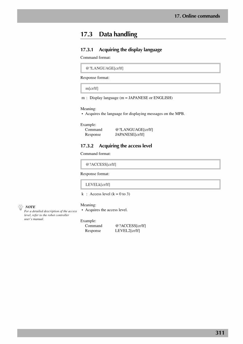
311
2
17. Online commands
n NOTEFor a detailed description of the accesslevel, refer to the robot controlleruser’s manual.
17.3 Data handling
17.3.1 Acquiring the display language
Command format:
@?LANGUAGE[cr/lf]
Response format:
m[cr/lf]
m : Display language (m = JAPANESE or ENGLISH)
Meaning:• Acquires the language for displaying messages on the MPB.
Example:Command @?LANGUAGE[cr/lf]Response JAPANESE[cr/lf]
17.3.2 Acquiring the access level
Command format:
@?ACCESS[cr/lf]
Response format:
LEVELk[cr/lf]
k : Access level (k = 0 to 3)
Meaning:• Acquires the access level.
Example:Command @?ACCESS[cr/lf]Response LEVEL2[cr/lf]
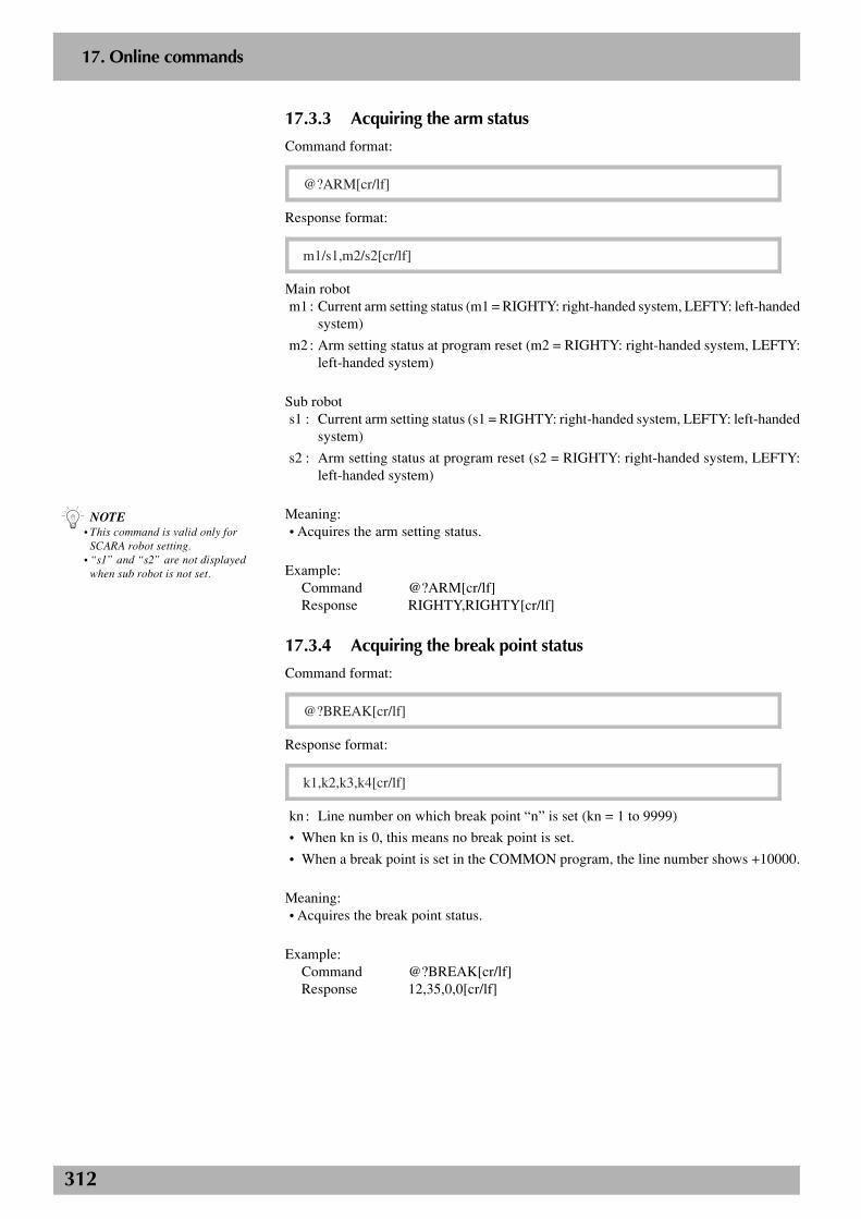
312
2
17. Online commands
17.3.3 Acquiring the arm status
Command format:
@?ARM[cr/lf]
Response format:
m1/s1,m2/s2[cr/lf]
Main robotm1 : Current arm setting status (m1 = RIGHTY: right-handed system, LEFTY: left-handed
system)
m2 : Arm setting status at program reset (m2 = RIGHTY: right-handed system, LEFTY:left-handed system)
Sub robots1 : Current arm setting status (s1 = RIGHTY: right-handed system, LEFTY: left-handed
system)
s2 : Arm setting status at program reset (s2 = RIGHTY: right-handed system, LEFTY:left-handed system)
Meaning:• Acquires the arm setting status.
Example:Command @?ARM[cr/lf]Response RIGHTY,RIGHTY[cr/lf]
17.3.4 Acquiring the break point status
Command format:
@?BREAK[cr/lf]
Response format:
k1,k2,k3,k4[cr/lf]
kn : Line number on which break point “n” is set (kn = 1 to 9999)
• When kn is 0, this means no break point is set.
• When a break point is set in the COMMON program, the line number shows +10000.
Meaning:• Acquires the break point status.
Example:Command @?BREAK[cr/lf]Response 12,35,0,0[cr/lf]
n NOTE• This command is valid only for
SCARA robot setting.• “s1” and “s2” are not displayed
when sub robot is not set.
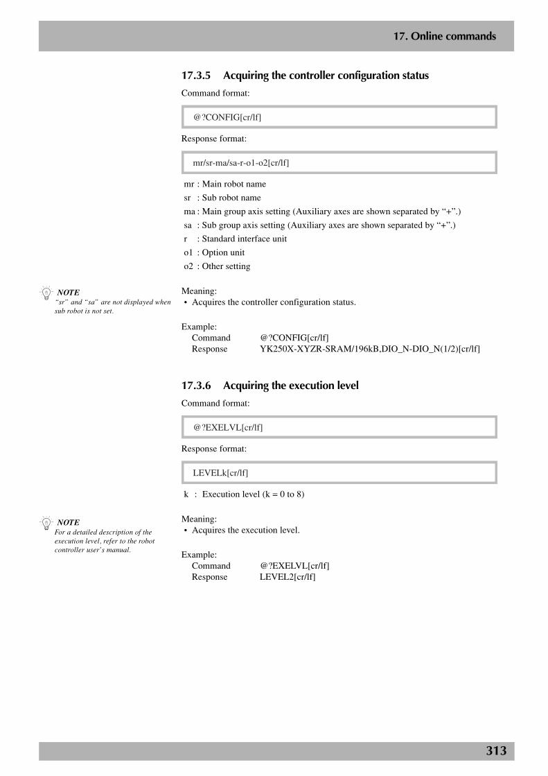
313
2
17. Online commands
17.3.5 Acquiring the controller configuration status
Command format:
@?CONFIG[cr/lf]
Response format:
mr/sr-ma/sa-r-o1-o2[cr/lf]
mr : Main robot name
sr : Sub robot name
ma : Main group axis setting (Auxiliary axes are shown separated by “+”.)
sa : Sub group axis setting (Auxiliary axes are shown separated by “+”.)
r : Standard interface unit
o1 : Option unit
o2 : Other setting
Meaning:• Acquires the controller configuration status.
Example:Command @?CONFIG[cr/lf]Response YK250X-XYZR-SRAM/196kB,DIO_N-DIO_N(1/2)[cr/lf]
17.3.6 Acquiring the execution level
Command format:
@?EXELVL[cr/lf]
Response format:
LEVELk[cr/lf]
k : Execution level (k = 0 to 8)
Meaning:• Acquires the execution level.
Example:Command @?EXELVL[cr/lf]Response LEVEL2[cr/lf]
n NOTE“sr” and “sa” are not displayed whensub robot is not set.
n NOTEFor a detailed description of theexecution level, refer to the robotcontroller user’s manual.
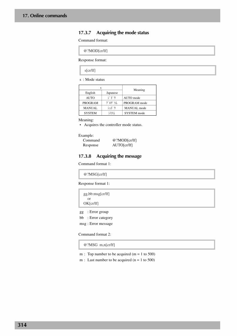
314
2
17. Online commands
17.3.7 Acquiring the mode status
Command format:
@?MOD[cr/lf]
Response format:
s[cr/lf]
s : Mode status
Japanese
ジドウ
プログラム
シュドウ
システム
English
AUTO
PROGRAM
MANUAL
SYSTEM
s
AUTO mode
PROGRAM mode
MANUAL mode
SYSTEM mode
Meaning
Meaning:• Acquires the controller mode status.
Example:Command @?MOD[cr/lf]Response AUTO[cr/lf]
17.3.8 Acquiring the message
Command format 1:
@?MSG[cr/lf]
Response format 1:
gg,bb:msg[cr/lf] orOK[cr/lf]
gg : Error group
bb : Error category
msg : Error message
Command format 2:
@?MSG m,n[cr/lf]
m : Top number to be acquired (m = 1 to 500)
m : Last number to be acquired (n = 1 to 500)

315
2
17. Online commands
Response format 2:
yy/mm/dd,hh:mm:ss gg.bb:msg[cr/lf]
yy/mm/dd,hh:mm:ss gg.bb:msg[cr/lf] :OK[cr/lf]
yy/mm/dd : Date (year/month/day) when error occurred
hh:mm:ss : Time (hour:minute:second) when error occurred
gg : Error group
bb : Error category
msg : Error message
Meaning:• Command format 1 acquires information on the message line displayed on the MPB or
RPB.
• Command format 2 acquires error history message.
Example:Command @?MSG[cr/lf]Response 5.30: Undefined identifier[cr/lf] or OK[cr/lf]
Example:Command @?MSG 1,5[cr/lf]Response 01/10/28,14:20:20 5.30: Undefined identifier[cr/lf]
01/10/28,14:18:34 5.1: Syntax error[cr/lf]01/10/28,14:10:54 5.30: Undefined identifier[cr/lf]01/10/28,14:05:40 14.22: No start code(@)[cr/lf]01/10/28,14:05:00 5.52: Command doesn’t exist[cr/lf]OK[cr/lf]
17.3.9 Acquiring return-to-origin status
Command format:
@?ORIGIN[cr/lf]
Response format:
COMPLETE[cr/lf] or INCOMPLETE[cr/lf]
COMPLETE : Return-to-origin is complete.INCOMPLETE : Return-to-origin is incomplete.
Meaning:• Acquires return-to-origin status.
Example:Command @?ORIGIN[cr/lf]Response COMPLETE[cr/lf]
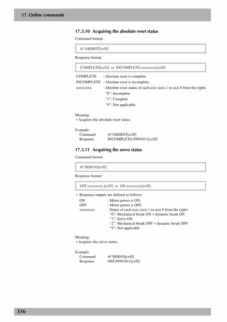
316
2
17. Online commands
17.3.10 Acquiring the absolute reset status
Command format:
@?ABSRST[cr/lf]
Response format:
COMPLETE[cr/lf] or INCOMPLETE,xxxxxxxx[cr/lf]
COMPLETE : Absolute reset is complete.
INCOMPLETE : Absolute reset is incomplete.
xxxxxxxx : Absolute reset status of each axis (axis 1 to axis 8 from the right)
“0”: Incomplete
“1”: Complete
“9”: Not applicable
Meaning:• Acquires the absolute reset status.
Example:Command @?ABSRST[cr/lf]Response INCOMPLETE,99991011[cr/lf]
17.3.11 Acquiring the servo status
Command format:
@?SERVO[cr/lf]
Response format:
OFF,xxxxxxxx [cr/lf] or ON,xxxxxxxx[cr/lf]
• Response outputs are defined as follows:
ON : Motor power is ON.OFF : Motor power is OFF.xxxxxxxx : Status of each axis (axis 1 to axis 8 from the right)
“0”: Mechanical break ON + dynamic break ON“1”: Servo ON“2”: Mechanical break OFF + dynamic break OFF“9”: Not applicable
Meaning:• Acquires the servo status.
Example:Command @?SERVO[cr/lf]Response OFF,99991011[cr/lf]
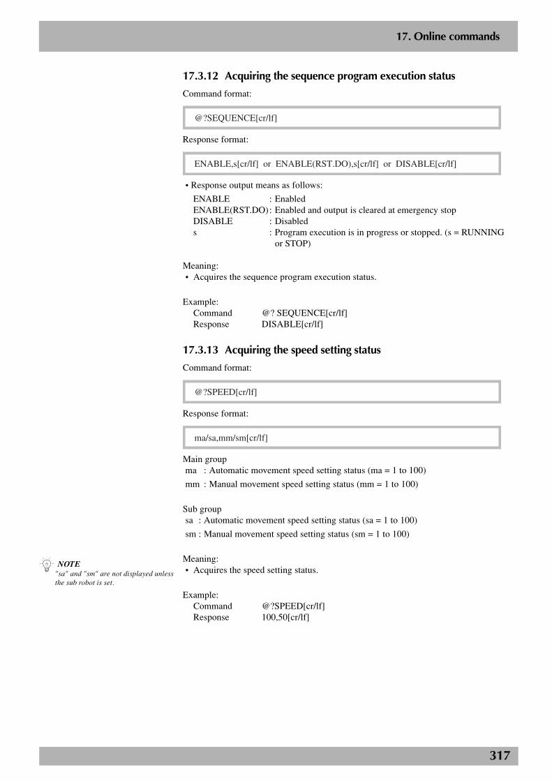
317
2
17. Online commands
17.3.12 Acquiring the sequence program execution status
Command format:
@?SEQUENCE[cr/lf]
Response format:
ENABLE,s[cr/lf] or ENABLE(RST.DO),s[cr/lf] or DISABLE[cr/lf]
• Response output means as follows:
ENABLE : EnabledENABLE(RST.DO): Enabled and output is cleared at emergency stopDISABLE : Disableds : Program execution is in progress or stopped. (s = RUNNING
or STOP)
Meaning:• Acquires the sequence program execution status.
Example:Command @? SEQUENCE[cr/lf]Response DISABLE[cr/lf]
17.3.13 Acquiring the speed setting status
Command format:
@?SPEED[cr/lf]
Response format:
ma/sa,mm/sm[cr/lf]
Main groupma : Automatic movement speed setting status (ma = 1 to 100)
mm : Manual movement speed setting status (mm = 1 to 100)
Sub groupsa : Automatic movement speed setting status (sa = 1 to 100)
sm : Manual movement speed setting status (sm = 1 to 100)
Meaning:• Acquires the speed setting status.
Example:Command @?SPEED[cr/lf]Response 100,50[cr/lf]
n NOTE"sa" and "sm" are not displayed unlessthe sub robot is set.
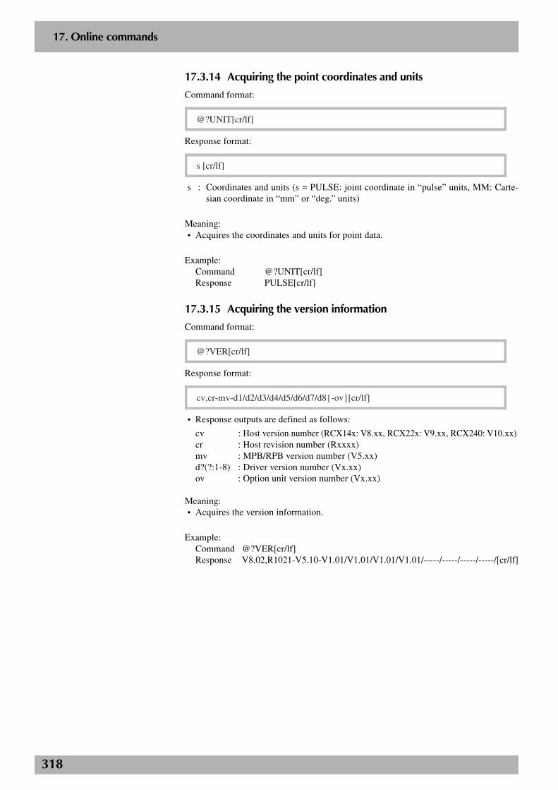
318
2
17. Online commands
17.3.14 Acquiring the point coordinates and units
Command format:
@?UNIT[cr/lf]
Response format:
s [cr/lf]
s : Coordinates and units (s = PULSE: joint coordinate in “pulse” units, MM: Carte-sian coordinate in “mm” or “deg.” units)
Meaning:• Acquires the coordinates and units for point data.
Example:Command @?UNIT[cr/lf]Response PULSE[cr/lf]
17.3.15 Acquiring the version information
Command format:
@?VER[cr/lf]
Response format:
cv,cr-mv-d1/d2/d3/d4/d5/d6/d7/d8{-ov}[cr/lf]
• Response outputs are defined as follows:
cv : Host version number (RCX14x: V8.xx, RCX22x: V9.xx, RCX240: V10.xx)cr : Host revision number (Rxxxx)mv : MPB/RPB version number (V5.xx)d?(?:1-8) : Driver version number (Vx.xx)ov : Option unit version number (Vx.xx)
Meaning:• Acquires the version information.
Example:Command @?VER[cr/lf]Response V8.02,R1021-V5.10-V1.01/V1.01/V1.01/V1.01/-----/-----/-----/-----/[cr/lf]
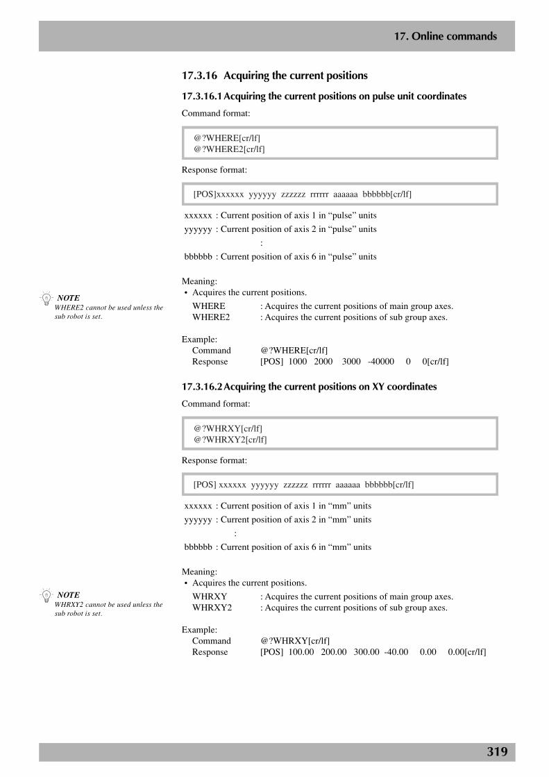
319
2
17. Online commands
n NOTEWHRXY2 cannot be used unless thesub robot is set.
17.3.16 Acquiring the current positions
17.3.16.1Acquiring the current positions on pulse unit coordinates
Command format:
@?WHERE[cr/lf]@?WHERE2[cr/lf]
Response format:
[POS]xxxxxx yyyyyy zzzzzz rrrrrr aaaaaa bbbbbb[cr/lf]
xxxxxx : Current position of axis 1 in “pulse” units
yyyyyy : Current position of axis 2 in “pulse” units
:
bbbbbb : Current position of axis 6 in “pulse” units
Meaning:• Acquires the current positions.
WHERE : Acquires the current positions of main group axes.WHERE2 : Acquires the current positions of sub group axes.
Example:Command @?WHERE[cr/lf]Response [POS] 1000 2000 3000 -40000 0 0[cr/lf]
17.3.16.2Acquiring the current positions on XY coordinates
Command format:
@?WHRXY[cr/lf]@?WHRXY2[cr/lf]
Response format:
[POS] xxxxxx yyyyyy zzzzzz rrrrrr aaaaaa bbbbbb[cr/lf]
xxxxxx : Current position of axis 1 in “mm” units
yyyyyy : Current position of axis 2 in “mm” units
:
bbbbbb : Current position of axis 6 in “mm” units
Meaning:• Acquires the current positions.
WHRXY : Acquires the current positions of main group axes.WHRXY2 : Acquires the current positions of sub group axes.
Example:Command @?WHRXY[cr/lf]Response [POS] 100.00 200.00 300.00 -40.00 0.00 0.00[cr/lf]
n NOTEWHERE2 cannot be used unless thesub robot is set.
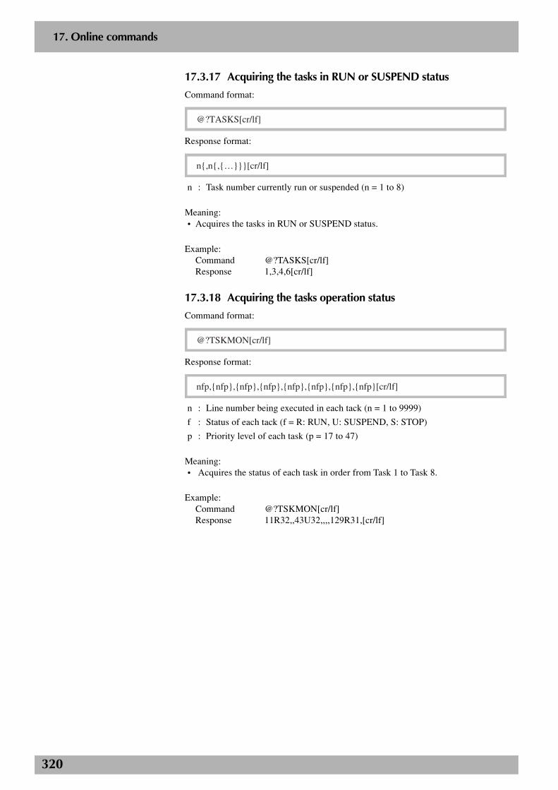
320
2
17. Online commands
17.3.17 Acquiring the tasks in RUN or SUSPEND status
Command format:
@?TASKS[cr/lf]
Response format:
n{,n{,{…}}}[cr/lf]
n : Task number currently run or suspended (n = 1 to 8)
Meaning:• Acquires the tasks in RUN or SUSPEND status.
Example:Command @?TASKS[cr/lf]Response 1,3,4,6[cr/lf]
17.3.18 Acquiring the tasks operation status
Command format:
@?TSKMON[cr/lf]
Response format:
nfp,{nfp},{nfp},{nfp},{nfp},{nfp},{nfp},{nfp}[cr/lf]
n : Line number being executed in each tack (n = 1 to 9999)
f : Status of each tack (f = R: RUN, U: SUSPEND, S: STOP)
p : Priority level of each task (p = 17 to 47)
Meaning:• Acquires the status of each task in order from Task 1 to Task 8.
Example:Command @?TSKMON[cr/lf]Response 11R32,,43U32,,,,129R31,[cr/lf]

321
2
17. Online commands
17.3.19 Acquiring the shift status
Command format:
@?SHIFT[cr/lf]
Response format:
m/s[cr/lf]
m : Shift number selected for main robot (m = 0 to 9)
s : Shift number selected for sub robot (s = 0 to 9)
Meaning:• Acquires the shift status.
Example:Command @?SHIFT[cr/lf]Response 1[cr/lf]
17.3.20 Acquiring the hand status
Command format:
@?HAND[cr/lf]
Response format:
m/s[cr/lf]
m : Hand number selected for main robot (m = 0 to 3)
s : Hand number selected for sub robot (s = 4 to 7)
Meaning:• Acquires the hand status.
Example:Command @?HAND[cr/lf]Response 1[cr/lf]
n NOTE"s" is not displayed unless the subrobot is set.
n NOTE"s" is not displayed unless the subrobot is set.
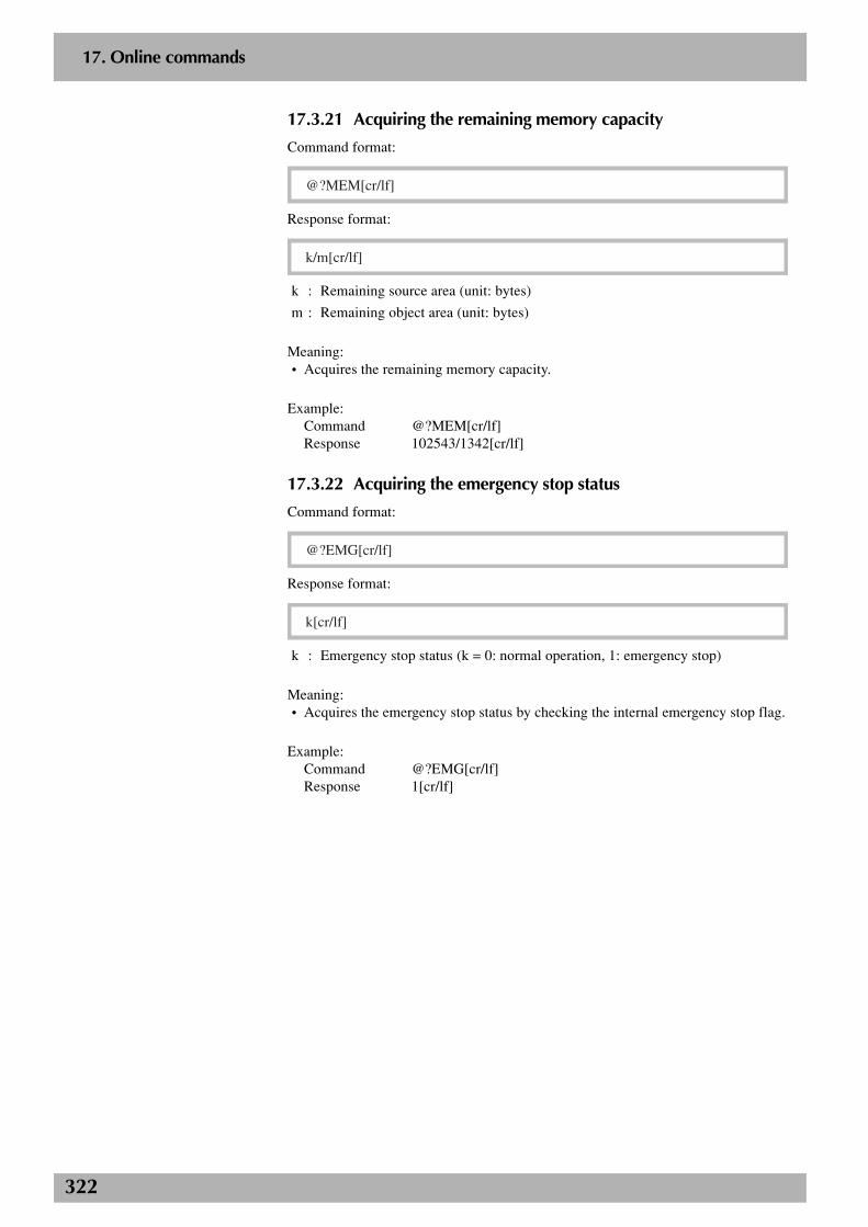
322
2
17. Online commands
17.3.21 Acquiring the remaining memory capacity
Command format:
@?MEM[cr/lf]
Response format:
k/m[cr/lf]
k : Remaining source area (unit: bytes)
m : Remaining object area (unit: bytes)
Meaning:• Acquires the remaining memory capacity.
Example:Command @?MEM[cr/lf]Response 102543/1342[cr/lf]
17.3.22 Acquiring the emergency stop status
Command format:
@?EMG[cr/lf]
Response format:
k[cr/lf]
k : Emergency stop status (k = 0: normal operation, 1: emergency stop)
Meaning:• Acquires the emergency stop status by checking the internal emergency stop flag.
Example:Command @?EMG[cr/lf]Response 1[cr/lf]
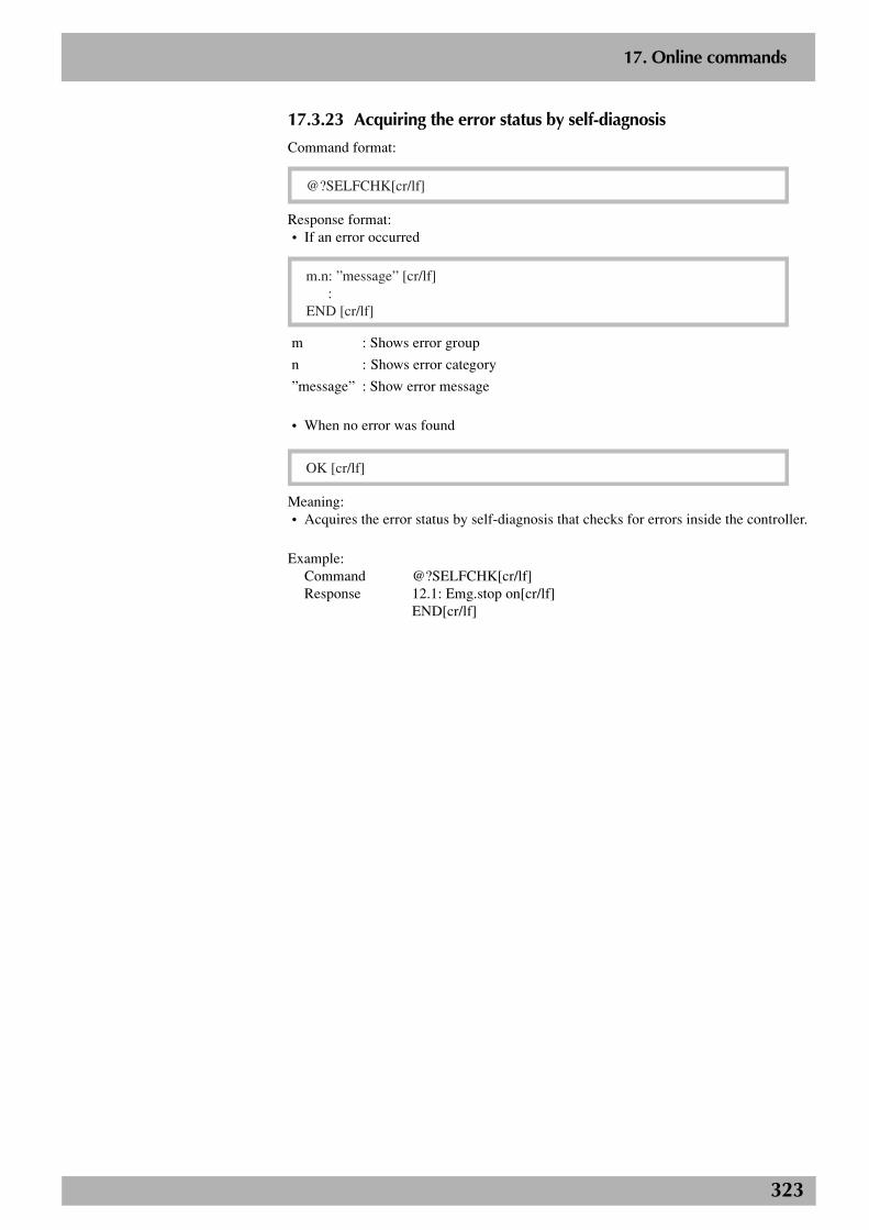
323
2
17. Online commands
17.3.23 Acquiring the error status by self-diagnosis
Command format:
@?SELFCHK[cr/lf]
Response format:• If an error occurred
m.n: ”message” [cr/lf] :END [cr/lf]
m : Shows error group
n : Shows error category
”message” : Show error message
• When no error was found
OK [cr/lf]
Meaning:• Acquires the error status by self-diagnosis that checks for errors inside the controller.
Example:Command @?SELFCHK[cr/lf]Response 12.1: Emg.stop on[cr/lf]
END[cr/lf]

324
2
17. Online commands
17.3.24 Acquiring the option slot status
Command format:
@?OPSLOT[cr/lf]
Response format:
OP.1 : ”option board name” [cr/lf]OP.2 : ”option board name” [cr/lf]OP.3 : ”option board name” [cr/lf]OP.4 : ”option board name” [cr/lf]
“option boar name” : Name of option board installed in the controller.DIO_Nm : DIO board with NPN specifications (m: board ID)DIO_Pm : DIO board with PNP specifications (m: board ID)CCLnk : CC-Link compatible boardD_Net : DeviceNet compatible boardProfi : Profibus compatible boardE_Net : Ethernet compatible boardYCLnk : YC-Link compatible boardno board : No option board is installed.illegal board : Incompatible board is installed.
Meaning:• Acquires the option slot status by checking the option boards.
Example:Command @?OPSLOT[cr/lf]Response OP.1 : DIO_N2[cr/lf]
OP.2 : DIO_N1[cr/lf]OP.3 : no board[cr/lf]OP.4 : CCLnk [cr/lf]
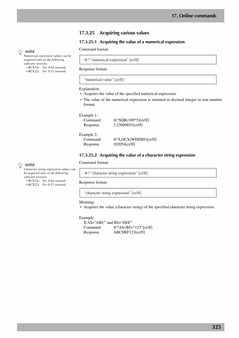
325
2
17. Online commands
17.3.25 Acquiring various values
17.3.25.1 Acquiring the value of a numerical expression
Command format:
@? “numerical expression” [cr/lf]
Response format:
“numerical value” [cr/lf]
Explanation:• Acquires the value of the specified numerical expression.
• The value of the numerical expression is returned in decimal integer or real numberformat.
Example 1:Command @?SQR(100*5)[cr/lf]Response 2.23606E01[cr/lf]
Example 2:Command @?LOCX(WHERE)[cr/lf]Response 102054[cr/lf]
17.3.25.2 Acquiring the value of a character string expression
Command format:
@? “character string expression” [cr/lf]
Response format:
“character string expression” [cr/lf]
Meaning:• Acquires the value (character string) of the specified character string expression.
Example:If A$=“ABC” and B$=“DEF”Command @?A$+B$+“123”[cr/lf]Response ABCDEF123[cr/lf]
n NOTENumerical expression values can beacquired only on the followingsoftware versions. • RCX14x Ver. 8.64 onwards • RCX22x Ver. 9.11 onwards
n NOTECharacter string expression values canbe acquired only on the followingsoftware versions. • RCX14x Ver. 8.64 onwards • RCX22x Ver. 9.11 onwards
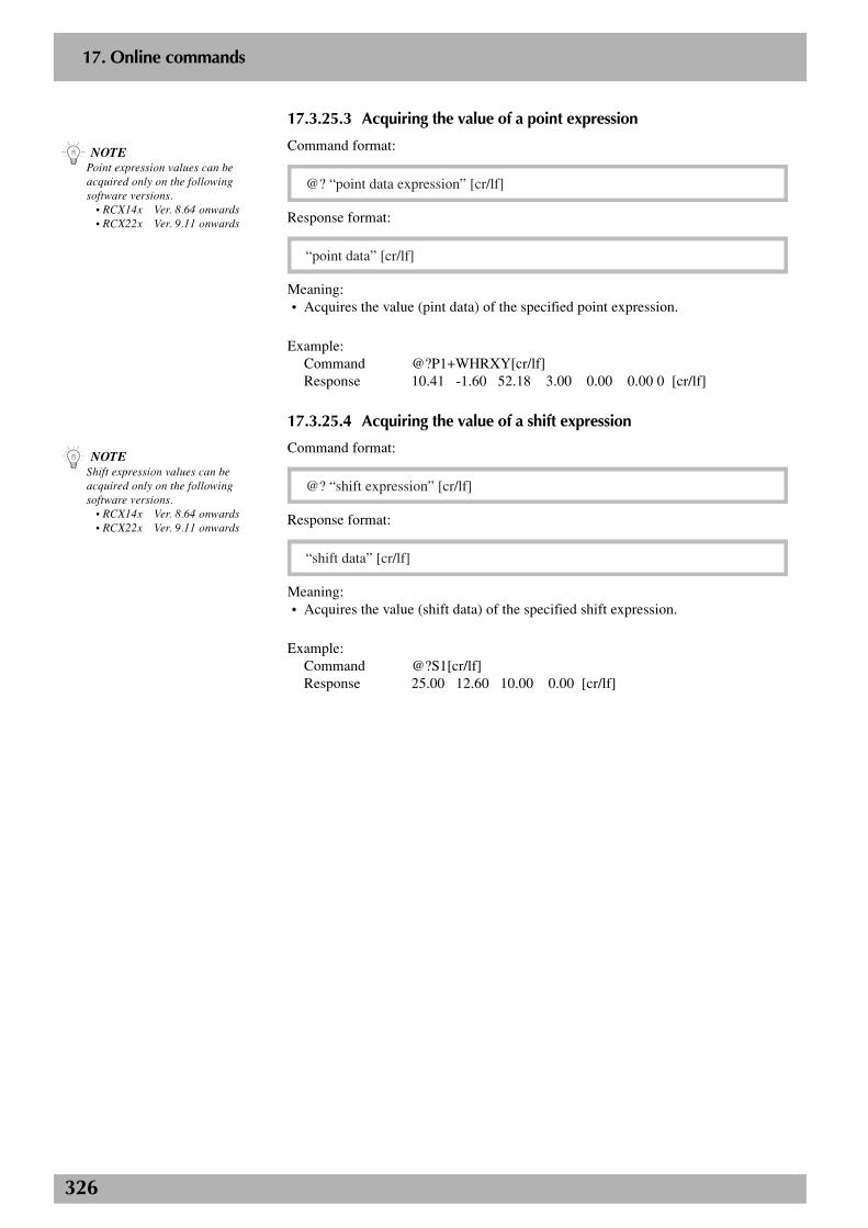
326
2
17. Online commands
17.3.25.3 Acquiring the value of a point expression
Command format:
@? “point data expression” [cr/lf]
Response format:
“point data” [cr/lf]
Meaning:• Acquires the value (pint data) of the specified point expression.
Example:Command @?P1+WHRXY[cr/lf]Response 10.41 -1.60 52.18 3.00 0.00 0.00 0 [cr/lf]
17.3.25.4 Acquiring the value of a shift expression
Command format:
@? “shift expression” [cr/lf]
Response format:
“shift data” [cr/lf]
Meaning:• Acquires the value (shift data) of the specified shift expression.
Example:Command @?S1[cr/lf]Response 25.00 12.60 10.00 0.00 [cr/lf]
n NOTEPoint expression values can beacquired only on the followingsoftware versions. • RCX14x Ver. 8.64 onwards • RCX22x Ver. 9.11 onwards
n NOTEShift expression values can beacquired only on the followingsoftware versions. • RCX14x Ver. 8.64 onwards • RCX22x Ver. 9.11 onwards
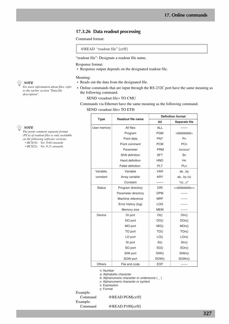
327
2
17. Online commands
17.3.26 Data readout processing
Command format:
@READ “readout file” [cr/lf]
“readout file”: Designate a readout file name.
Response format:• Response output depends on the designated readout file.
Meaning:• Reads out the data from the designated file.
• Online commands that are input through the RS-232C port have the same meaning asthe following command.
SEND <readout file> TO CMU
Commands via Ethernet have the same meaning as the following command.
SEND <readout file> TO ETH
Type Readout file nameDefinition format
All Separate file
User memory
Variable,
constant
Status
Device
Others
All files
Program
Point data
Point comment
Parameter
Shift definition
Hand definition
Pallet definition
Variable
Array variable
Constant
Program directory
Parameter directory
Machine reference
Error history (log)
Memory size
DI port
DO port
MO port
TO port
LO port
SI port
SO port
SIW port
SOW port
File end code
ALL
PGM
PNT
PCM
PRM
SFT
HND
PLT
VAR
ARY
––––
DIR
DPM
MRF
LOG
MEM
DI()
DO()
MO()
TO()
LO()
SI()
SO()
SIW()
SOW()
EOF
––––
<bbbbbbbb>
Pn
PCn
/cccccc/
Sn
Hn
PLn
ab...by
ab...by (x)
“cc...c”
<<bbbbbbbb>>
––––
––––
––––
––––
DIn()
DOn()
MOn()
TOn()
LOn()
SIn()
SOn()
SIWn()
SOWn()
––––
n: Numbera: Alphabetic characterb: Alphanumeric character or underscore ( _ )c: Alphanumeric character or symbolx: Expressiony: Format
Example:Command @READ PGM[cr/lf]
Example:Command @READ P100[cr/lf]
n NOTEThe point comment separate format(PCn) of readout files is only availableon the following software versions. • RCX14x Ver. 8.64 onwards • RCX22x Ver. 9.11 onwards
n NOTEFor more information about files, referto the earlier section "Data filedescription".
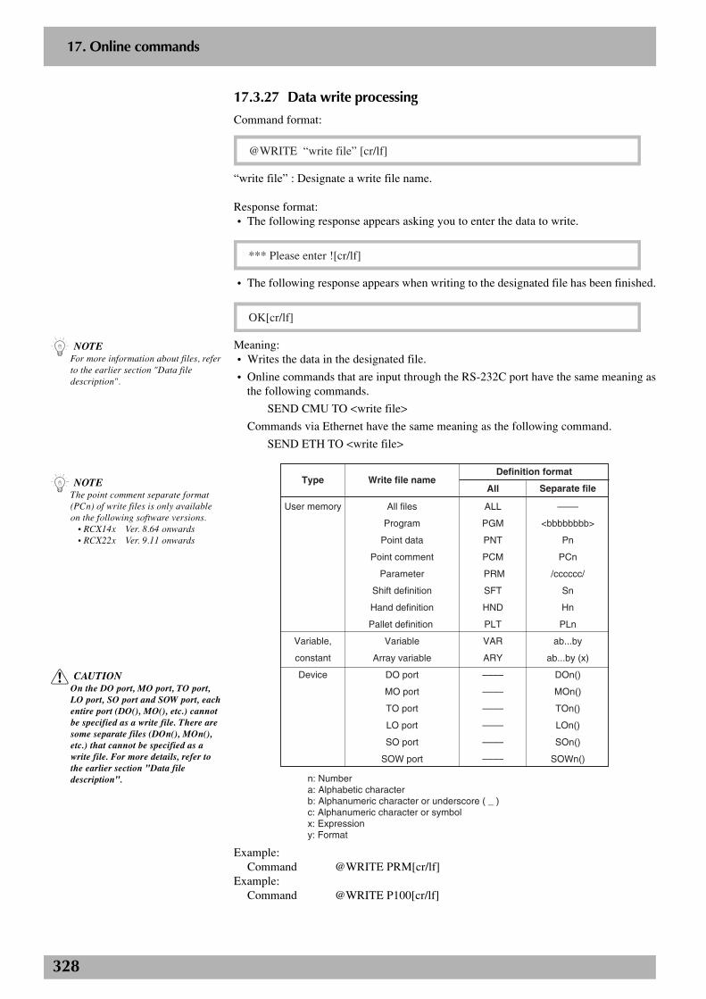
328
2
17. Online commands
17.3.27 Data write processing
Command format:
@WRITE “write file” [cr/lf]
“write file” : Designate a write file name.
Response format:• The following response appears asking you to enter the data to write.
*** Please enter ![cr/lf]
• The following response appears when writing to the designated file has been finished.
OK[cr/lf]
Meaning:• Writes the data in the designated file.
• Online commands that are input through the RS-232C port have the same meaning asthe following commands.
SEND CMU TO <write file>
Commands via Ethernet have the same meaning as the following command.
SEND ETH TO <write file>
Type Write file nameDefinition format
All Separate file
User memory
Variable,
constant
Device
All files
Program
Point data
Point comment
Parameter
Shift definition
Hand definition
Pallet definition
Variable
Array variable
DO port
MO port
TO port
LO port
SO port
SOW port
ALL
PGM
PNT
PCM
PRM
SFT
HND
PLT
VAR
ARY
––––
––––
––––
––––
––––
––––
––––
<bbbbbbbb>
Pn
PCn
/cccccc/
Sn
Hn
PLn
ab...by
ab...by (x)
DOn()
MOn()
TOn()
LOn()
SOn()
SOWn()
n: Numbera: Alphabetic characterb: Alphanumeric character or underscore ( _ )c: Alphanumeric character or symbolx: Expressiony: Format
Example:Command @WRITE PRM[cr/lf]
Example:Command @WRITE P100[cr/lf]
n NOTEFor more information about files, referto the earlier section "Data filedescription".
n NOTEThe point comment separate format(PCn) of write files is only availableon the following software versions. • RCX14x Ver. 8.64 onwards • RCX22x Ver. 9.11 onwards
c CAUTIONOn the DO port, MO port, TO port,LO port, SO port and SOW port, eachentire port (DO(), MO(), etc.) cannotbe specified as a write file. There aresome separate files (DOn(), MOn(),etc.) that cannot be specified as awrite file. For more details, refer tothe earlier section "Data filedescription".
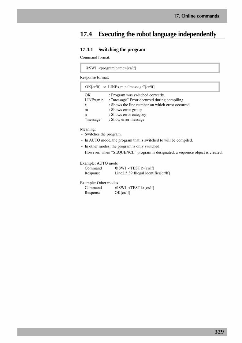
329
2
17. Online commands
17.4 Executing the robot language independently
17.4.1 Switching the program
Command format:
@SWI <program name>[cr/lf]
Response format:
OK[cr/lf] or LINEx,m,n:”message”[cr/lf]
OK : Program was switched correctly.LINEx,m,n : ”message” Error occurred during compiling.x : Shows the line number on which error occurred.m : Shows error groupn : Shows error category”message” : Show error message
Meaning:• Switches the program.
• In AUTO mode, the program that is switched to will be compiled.
• In other modes, the program is only switched.
However, when “SEQUENCE” program is designated, a sequence object is created.
Example: AUTO modeCommand @SWI <TEST1>[cr/lf]Response Line2,5.39:Illegal identifier[cr/lf]
Example: Other modesCommand @SWI <TEST1>[cr/lf]Response OK[cr/lf]
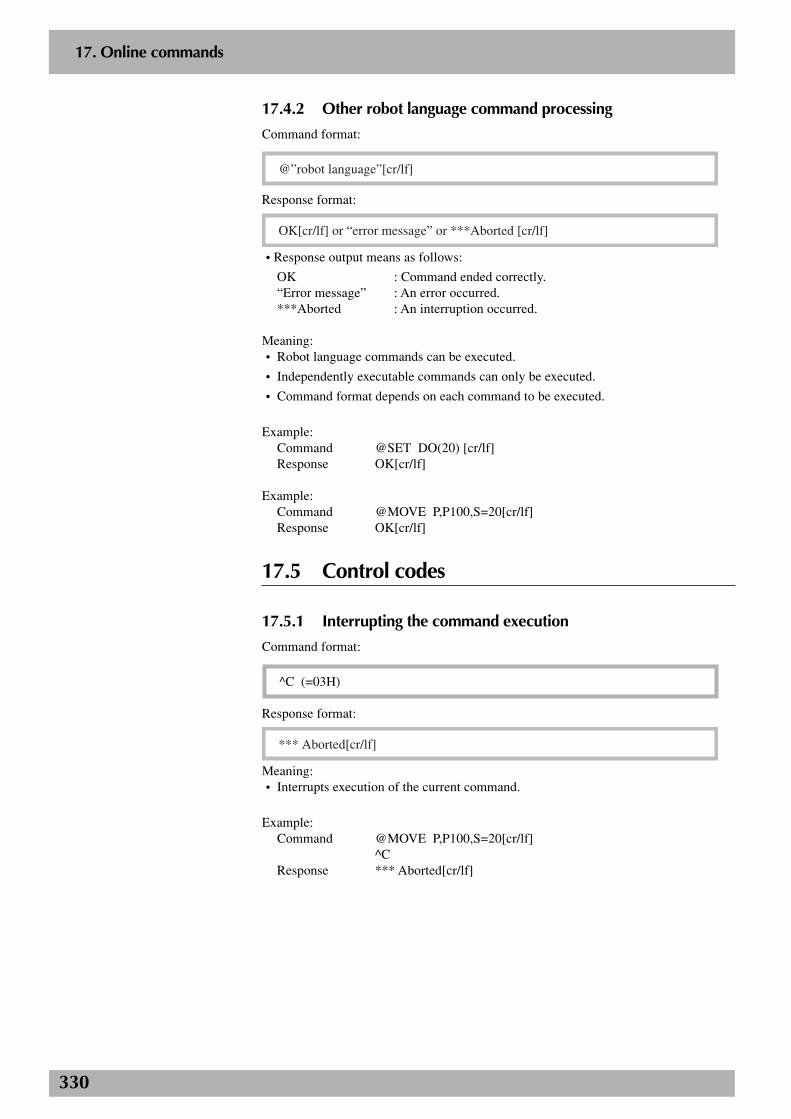
330
2
17. Online commands
17.4.2 Other robot language command processing
Command format:
@”robot language”[cr/lf]
Response format:
OK[cr/lf] or “error message” or ***Aborted [cr/lf]
• Response output means as follows:
OK : Command ended correctly.“Error message” : An error occurred.***Aborted : An interruption occurred.
Meaning:• Robot language commands can be executed.
• Independently executable commands can only be executed.
• Command format depends on each command to be executed.
Example:Command @SET DO(20) [cr/lf]Response OK[cr/lf]
Example:Command @MOVE P,P100,S=20[cr/lf]Response OK[cr/lf]
17.5 Control codes
17.5.1 Interrupting the command execution
Command format:
^C (=03H)
Response format:
*** Aborted[cr/lf]
Meaning:• Interrupts execution of the current command.
Example:Command @MOVE P,P100,S=20[cr/lf]
^CResponse *** Aborted[cr/lf]
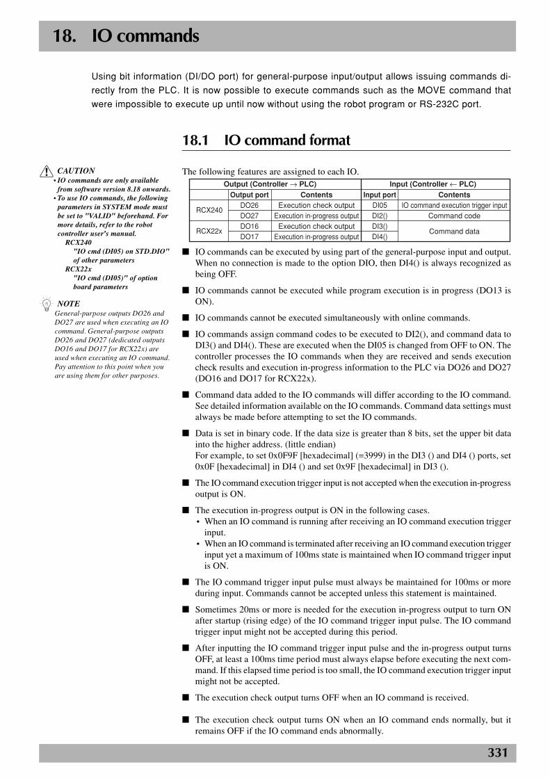
331
18. IO commands
18.1 IO command format
The following features are assigned to each IO.Output (Controller → PLC) Input (Controller ← PLC)
Output portDO26DO27DO16DO17
RCX240
RCX22x
Input portDI05DI2()DI3()DI4()
ContentsExecution check output
Execution in-progress outputExecution check output
Execution in-progress output
ContentsIO command execution trigger input
Command code
Command data
■ IO commands can be executed by using part of the general-purpose input and output.When no connection is made to the option DIO, then DI4() is always recognized asbeing OFF.
■ IO commands cannot be executed while program execution is in progress (DO13 isON).
■ IO commands cannot be executed simultaneously with online commands.
■ IO commands assign command codes to be executed to DI2(), and command data toDI3() and DI4(). These are executed when the DI05 is changed from OFF to ON. Thecontroller processes the IO commands when they are received and sends executioncheck results and execution in-progress information to the PLC via DO26 and DO27(DO16 and DO17 for RCX22x).
■ Command data added to the IO commands will differ according to the IO command.See detailed information available on the IO commands. Command data settings mustalways be made before attempting to set the IO commands.
■ Data is set in binary code. If the data size is greater than 8 bits, set the upper bit datainto the higher address. (little endian)For example, to set 0x0F9F [hexadecimal] (=3999) in the DI3 () and DI4 () ports, set0x0F [hexadecimal] in DI4 () and set 0x9F [hexadecimal] in DI3 ().
■ The IO command execution trigger input is not accepted when the execution in-progressoutput is ON.
■ The execution in-progress output is ON in the following cases.• When an IO command is running after receiving an IO command execution trigger
input.• When an IO command is terminated after receiving an IO command execution trigger
input yet a maximum of 100ms state is maintained when IO command trigger inputis ON.
■ The IO command trigger input pulse must always be maintained for 100ms or moreduring input. Commands cannot be accepted unless this statement is maintained.
■ Sometimes 20ms or more is needed for the execution in-progress output to turn ONafter startup (rising edge) of the IO command trigger input pulse. The IO commandtrigger input might not be accepted during this period.
■ After inputting the IO command trigger input pulse and the in-progress output turnsOFF, at least a 100ms time period must always elapse before executing the next com-mand. If this elapsed time period is too small, the IO command execution trigger inputmight not be accepted.
■ The execution check output turns OFF when an IO command is received.
■ The execution check output turns ON when an IO command ends normally, but itremains OFF if the IO command ends abnormally.
Using bit information (DI/DO port) for general-purpose input/output allows issuing commands di-
rectly from the PLC. It is now possible to execute commands such as the MOVE command that
were impossible to execute up until now without using the robot program or RS-232C port.
c CAUTION• IO commands are only available
from software version 8.18 onwards.• To use IO commands, the following
parameters in SYSTEM mode mustbe set to "VALID" beforehand. Formore details, refer to the robotcontroller user's manual.
RCX240"IO cmd (DI05) on STD.DIO"of other parameters
RCX22x"IO cmd (DI05)" of optionboard parameters
n NOTEGeneral-purpose outputs DO26 andDO27 are used when executing an IOcommand. General-purpose outputsDO26 and DO27 (dedicated outputsDO16 and DO17 for RCX22x) areused when executing an IO command.Pay attention to this point when youare using them for other purposes.
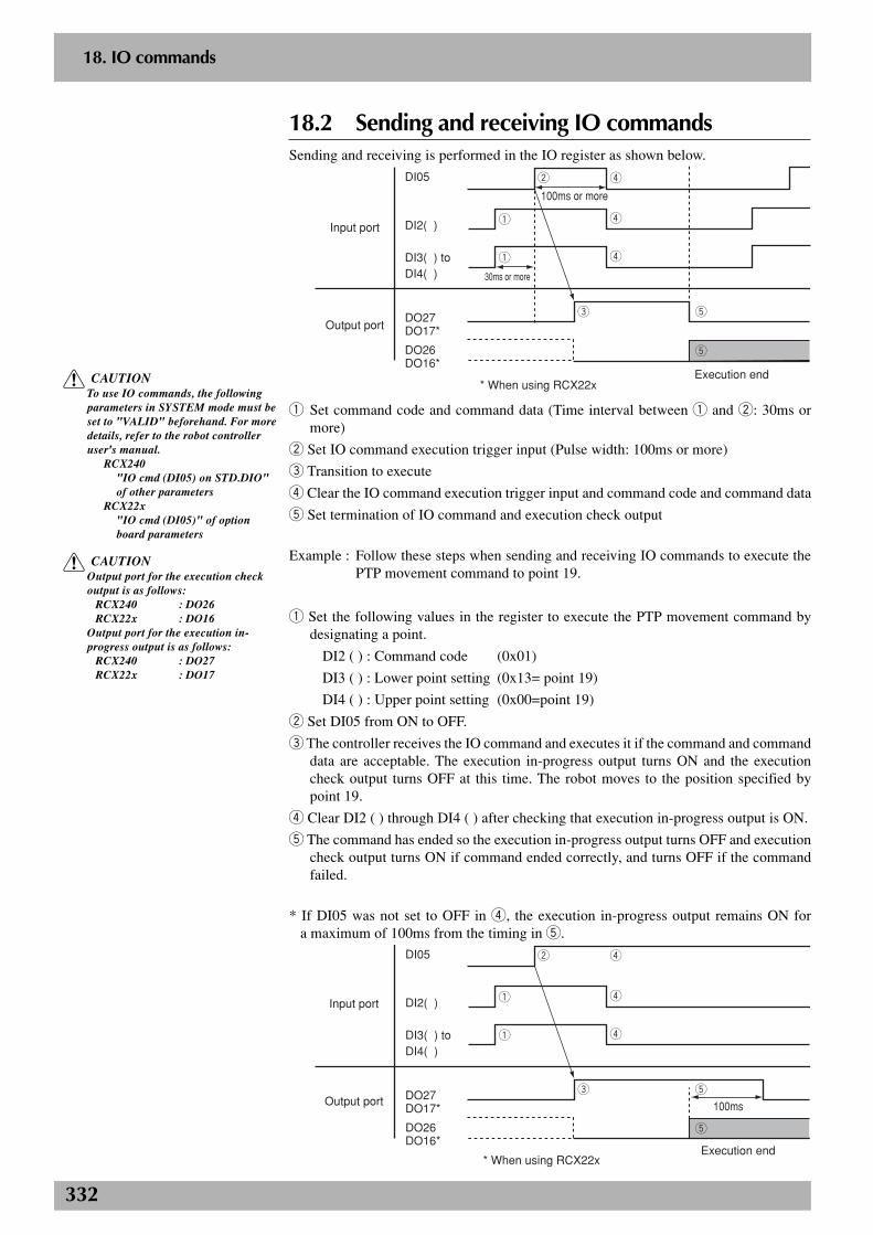
332
2
18. IO commands
18.2 Sending and receiving IO commandsSending and receiving is performed in the IO register as shown below.
q
e t
t
w r
r
q r
Input port
Output port
Execution end
100ms or more
30ms or more
DI05
DI2( )
DI3( ) to DI4( )
DO27DO17*
DO26DO16*
* When using RCX22x
q Set command code and command data (Time interval between q and w: 30ms ormore)
w Set IO command execution trigger input (Pulse width: 100ms or more)
e Transition to execute
r Clear the IO command execution trigger input and command code and command data
t Set termination of IO command and execution check output
Example : Follow these steps when sending and receiving IO commands to execute thePTP movement command to point 19.
q Set the following values in the register to execute the PTP movement command bydesignating a point.
DI2 ( ) : Command code (0x01)
DI3 ( ) : Lower point setting (0x13= point 19)
DI4 ( ) : Upper point setting (0x00=point 19)
w Set DI05 from ON to OFF.
e The controller receives the IO command and executes it if the command and commanddata are acceptable. The execution in-progress output turns ON and the executioncheck output turns OFF at this time. The robot moves to the position specified bypoint 19.
r Clear DI2 ( ) through DI4 ( ) after checking that execution in-progress output is ON.
t The command has ended so the execution in-progress output turns OFF and executioncheck output turns ON if command ended correctly, and turns OFF if the commandfailed.
* If DI05 was not set to OFF in r, the execution in-progress output remains ON for a maximum of 100ms from the timing in t.
q
e t
t
w r
r
q r
Input port
Output port
Execution end
100ms
DI05
DI2( )
DI3( ) to DI4( )
DO27DO17*
DO26DO16*
* When using RCX22x
c CAUTIONOutput port for the execution checkoutput is as follows:
RCX240 : DO26RCX22x : DO16
Output port for the execution in-progress output is as follows:
RCX240 : DO27RCX22x : DO17
c CAUTIONTo use IO commands, the followingparameters in SYSTEM mode must beset to "VALID" beforehand. For moredetails, refer to the robot controlleruser's manual.
RCX240"IO cmd (DI05) on STD.DIO"of other parameters
RCX22x"IO cmd (DI05)" of optionboard parameters
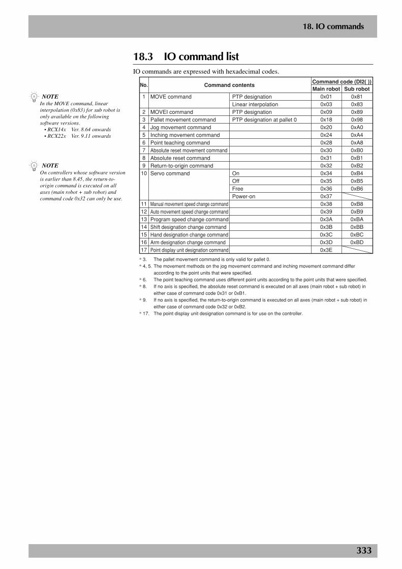
333
2
18. IO commands
18.3 IO command listIO commands are expressed with hexadecimal codes.
Command contentsCommand code (DI2( ))Main robot Sub robot
0x010x030x090x180x200x240x280x300x310x320x340x350x360x370x380x390x3A0x3B0x3C0x3D0x3E
0x810x830x890x980xA00xA40xA80xB00xB10xB20xB40xB50xB6
0xB80xB90xBA0xBB0xBC0xBD
No.
1
2345678910
11121314151617
MOVE command
MOVEI commandPallet movement commandJog movement commandInching movement commandPoint teaching commandAbsolute reset movement commandAbsolute reset commandReturn-to-origin commandServo command
Manual movement speed change commandAuto movement speed change commandProgram speed change commandShift designation change commandHand designation change commandArm designation change commandPoint display unit designation command
PTP designationLinear interpolationPTP designationPTP designation at pallet 0
OnOffFreePower-on
* 3. The pallet movement command is only valid for pallet 0.* 4, 5. The movement methods on the jog movement command and inching movement command differ
according to the point units that were specified.* 6. The point teaching command uses different point units according to the point units that were specified.* 8. If no axis is specified, the absolute reset command is executed on all axes (main robot + sub robot) in
either case of command code 0x31 or 0xB1.* 9. If no axis is specified, the return-to-origin command is executed on all axes (main robot + sub robot) in
either case of command code 0x32 or 0xB2.* 17. The point display unit designation command is for use on the controller.
n NOTEIn the MOVE command, linearinterpolation (0x83) for sub robot isonly available on the followingsoftware versions. • RCX14x Ver. 8.64 onwards • RCX22x Ver. 9.11 onwards
n NOTEOn controllers whose software versionis earlier than 8.45, the return-to-origin command is executed on allaxes (main robot + sub robot) andcommand code 0x32 can only be use.
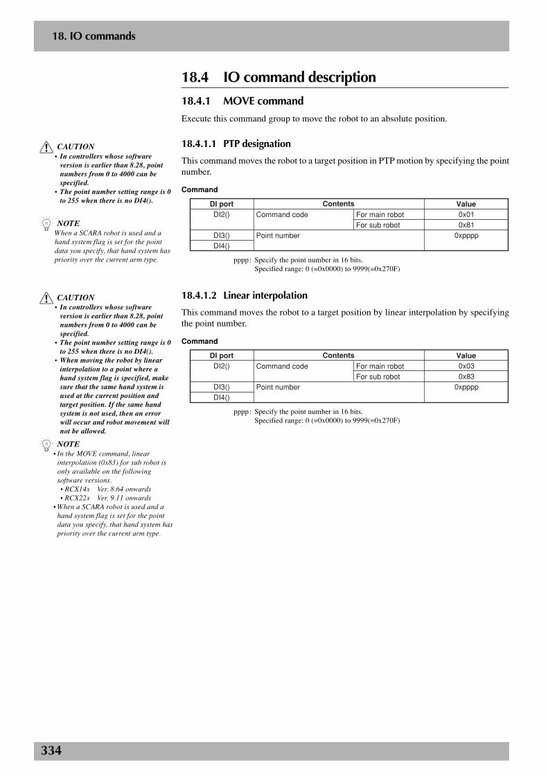
334
2
18. IO commands
18.4 IO command description
18.4.1 MOVE command
Execute this command group to move the robot to an absolute position.
18.4.1.1 PTP designation
This command moves the robot to a target position in PTP motion by specifying the pointnumber.
Command
Contents Value0x010x81
0xpppp
DI portDI2()
DI3()DI4()
Command code
Point number
For main robot For sub robot
pppp: Specify the point number in 16 bits.Specified range: 0 (=0x0000) to 9999(=0x270F)
18.4.1.2 Linear interpolation
This command moves the robot to a target position by linear interpolation by specifyingthe point number.
Command
Contents Value0x030x83
0xpppp
DI portDI2()
DI3()DI4()
Command code
Point number
For main robot For sub robot
pppp: Specify the point number in 16 bits.Specified range: 0 (=0x0000) to 9999(=0x270F)
c CAUTION• In controllers whose software
version is earlier than 8.28, pointnumbers from 0 to 4000 can bespecified.
• The point number setting range is 0to 255 when there is no DI4().
n NOTEWhen a SCARA robot is used and ahand system flag is set for the pointdata you specify, that hand system haspriority over the current arm type.
c CAUTION• In controllers whose software
version is earlier than 8.28, pointnumbers from 0 to 4000 can bespecified.
• The point number setting range is 0to 255 when there is no DI4().
• When moving the robot by linearinterpolation to a point where ahand system flag is specified, makesure that the same hand system isused at the current position andtarget position. If the same handsystem is not used, then an errorwill occur and robot movement willnot be allowed.
n NOTE• In the MOVE command, linear
interpolation (0x83) for sub robot isonly available on the followingsoftware versions.
• RCX14x Ver. 8.64 onwards • RCX22x Ver. 9.11 onwards• When a SCARA robot is used and a
hand system flag is set for the pointdata you specify, that hand system haspriority over the current arm type.
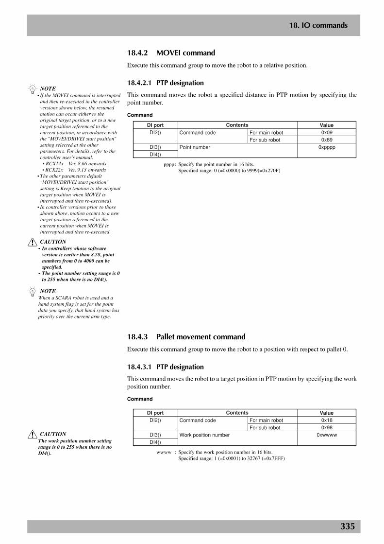
335
2
18. IO commands
18.4.2 MOVEI command
Execute this command group to move the robot to a relative position.
18.4.2.1 PTP designation
This command moves the robot a specified distance in PTP motion by specifying thepoint number.
Command
Contents Value0x090x89
0xpppp
DI portDI2()
DI3()DI4()
Command code
Point number
For main robot For sub robot
pppp: Specify the point number in 16 bits.Specified range: 0 (=0x0000) to 9999(=0x270F)
18.4.3 Pallet movement command
Execute this command group to move the robot to a position with respect to pallet 0.
18.4.3.1 PTP designation
This command moves the robot to a target position in PTP motion by specifying the workposition number.
Command
Contents Value0x180x98
0xwwww
DI portDI2()
DI3()DI4()
Command code
Work position number
For main robot For sub robot
wwww : Specify the work position number in 16 bits.Specified range: 1 (=0x0001) to 32767 (=0x7FFF)
c CAUTIONThe work position number settingrange is 0 to 255 when there is noDI4().
c CAUTION• In controllers whose software
version is earlier than 8.28, pointnumbers from 0 to 4000 can bespecified.
• The point number setting range is 0to 255 when there is no DI4().
n NOTEWhen a SCARA robot is used and ahand system flag is set for the pointdata you specify, that hand system haspriority over the current arm type.
n NOTE• If the MOVEI command is interrupted
and then re-executed in the controllerversions shown below, the resumedmotion can occur either to theoriginal target position, or to a newtarget position referenced to thecurrent position, in accordance withthe "MOVEI/DRIVEI start position"setting selected at the otherparameters. For details, refer to thecontroller user's manual.
• RCX14x Ver. 8.66 onwards • RCX22x Ver. 9.13 onwards• The other parameters default
"MOVEI/DRIVEI start position"setting is Keep (motion to the originaltarget position when MOVEI isinterrupted and then re-executed).
• In controller versions prior to thoseshown above, motion occurs to a newtarget position referenced to thecurrent position when MOVEI isinterrupted and then re-executed.
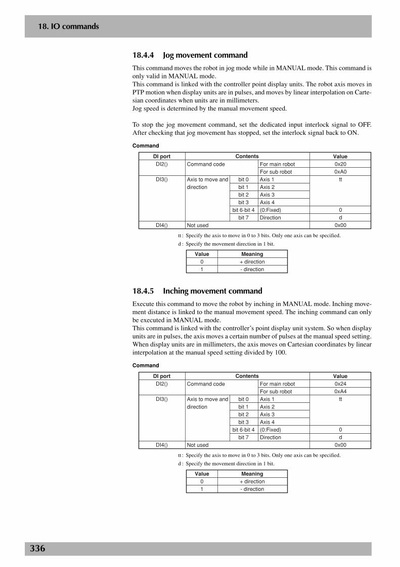
336
2
18. IO commands
18.4.4 Jog movement command
This command moves the robot in jog mode while in MANUAL mode. This command isonly valid in MANUAL mode.This command is linked with the controller point display units. The robot axis moves inPTP motion when display units are in pulses, and moves by linear interpolation on Carte-sian coordinates when units are in millimeters.Jog speed is determined by the manual movement speed.
To stop the jog movement command, set the dedicated input interlock signal to OFF.After checking that jog movement has stopped, set the interlock signal back to ON.
Command
Contents Value0x200xA0
tt
0d
0x00
DI portDI2()
DI3()
DI4()
Command code
Axis to move anddirection
Not used
For main robot For sub robot bit 0 Axis 1 bit 1 Axis 2 bit 2 Axis 3 bit 3 Axis 4 bit 6-bit 4 (0:Fixed) bit 7 Direction
tt : Specify the axis to move in 0 to 3 bits. Only one axis can be specified.
d : Specify the movement direction in 1 bit.
Value01
Meaning+ direction- direction
18.4.5 Inching movement command
Execute this command to move the robot by inching in MANUAL mode. Inching move-ment distance is linked to the manual movement speed. The inching command can onlybe executed in MANUAL mode.This command is linked with the controller’s point display unit system. So when displayunits are in pulses, the axis moves a certain number of pulses at the manual speed setting.When display units are in millimeters, the axis moves on Cartesian coordinates by linearinterpolation at the manual speed setting divided by 100.
Command
Contents Value0x240xA4
tt
0d
0x00
DI portDI2()
DI3()
DI4()
Command code
Axis to move and direction
Not used
For main robot For sub robot bit 0 Axis 1 bit 1 Axis 2 bit 2 Axis 3 bit 3 Axis 4 bit 6-bit 4 (0:Fixed) bit 7 Direction
tt : Specify the axis to move in 0 to 3 bits. Only one axis can be specified.
d : Specify the movement direction in 1 bit.
Value01
Meaning+ direction- direction
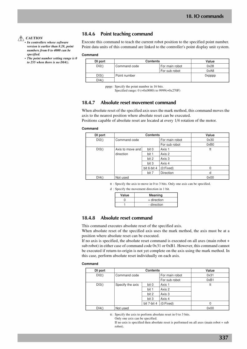
337
2
18. IO commands
18.4.6 Point teaching command
Execute this command to teach the current robot position to the specified point number.Point data units of this command are linked to the controller's point display unit system.
Command
Contents Value0x280xA8
0xpppp
DI portDI2()
DI3()DI4()
Command code
Point number
For main robot For sub robot
pppp: Specify the point number in 16 bits.Specified range: 0 (=0x0000) to 9999(=0x270F)
18.4.7 Absolute reset movement command
When absolute reset of the specified axis uses the mark method, this command moves theaxis to the nearest position where absolute reset can be executed.Positions capable of absolute reset are located at every 1/4 rotation of the motor.
Command
Contents Value0x300xB0
tt
0d
0x00
DI portDI2()
DI3()
DI4()
Command code
Axis to move anddirection
Not used
For main robot For sub robot bit 0 Axis 1 bit 1 Axis 2 bit 2 Axis 3 bit 3 Axis 4 bit 6-bit 4 (0:Fixed) bit 7 Direction
tt : Specify the axis to move in 0 to 3 bits. Only one axis can be specified.
d : Specify the movement direction in 1 bit.
Value01
Meaning+ direction- direction
18.4.8 Absolute reset command
This command executes absolute reset of the specified axis.When absolute reset of the specified axis uses the mark method, the axis must be at aposition where absolute reset can be executed.If no axis is specified, the absolute reset command is executed on all axes (main robot +sub robot) in either case of command code 0x31 or 0xB1. However, this command cannotbe executed if return-to-origin is not yet complete on the axis using the mark method. Inthis case, perform absolute reset individually on each axis.
Command
Contents Value0x310xB1
tt
00x00
DI portDI2()
DI3()
DI4()
Command code
Specify the axis
Not used
For main robot For sub robot bit 0 Axis 1 bit 1 Axis 2 bit 2 Axis 3 bit 3 Axis 4 bit 7-bit 4 (0:Fixed)
tt : Specify the axis to perform absolute reset in 0 to 3 bits.Only one axis can be specified.If no axis is specified then absolute reset is performed on all axes (main robot + subrobot).
c CAUTION• In controllers whose software
version is earlier than 8.28, pointnumbers from 0 to 4000 can bespecified.
• The point number setting range is 0to 255 when there is no DI4().

338
2
18. IO commands
18.4.9 Return-to-origin command
This command executes return-to-origin on a specified axis.When this command is executed on an incremental mode axis, that axis returns to itsorigin. When executed on a semi-absolute mode axis, an absolute search is performed onthat axis.If no axis is specified (DI3() is 0), this command is executed on all axes (main robot + subrobot) in either case of 0x32 or 0xB2.
Command
Contents Value0x320xB2
tt
00x00
DI portDI2()
DI3()
DI4()
Command code
Specify the axis
Not used
For main robot For sub robot bit 0 Axis 1 bit 1 Axis 2 bit 2 Axis 3 bit 3 Axis 4 bit 7-bit 4 (0:Fixed)
tt : Specify the axis to perform return-to-origin in 0 to 3 bits.Only one axis can be specified.If no axis is specified then this command is executed on all axes (main robot + subrobot).
18.4.10 Servo command
Execute this command group to operate the robot servos.ContentsOperation
Execute this command to turn on the servo of a specified axis. The motor power must be turned on when specifying the axis.All controller servos are turned on if no axis is specified.
Execute this command to turn off the servo of a specified axis. All controller servos are turned off if no axis is specified.
Execute this command to turn off the mechanical brake and dynamic brake after turning off the servo of a specified axis. Servo OFF and Free are repeated when this command is consecutively executed.All controller servos will be free if no axis is specified.
Execute this command to turn on the motor power.No axis can be specified.
Servo ON
Servo OFF
Servo Free
Power ON
Command
Contents Value0x340xB40x350xB50x360xB60x37
tt
00x00
DI portDI2()
DI3()
DI4()
Command code
Specify the axis
Not used
Servo ON For main robot For sub robot Servo OFF For main robot For sub robot Servo Free For main robot For sub robot Power ON All controller servos bit 0 Axis 1 bit 1 Axis 2 bit 2 Axis 3 bit 3 Axis 4 bit 7-bit 4 (0:Fixed)
tt : Specify the axis to move in 0 to 3 bits. All controller servos are processed if no axisis specified. No axis can be specified when executing Power ON.
n NOTEAn axis can be specified with thereturn-to-origin command fromsoftware version 8.45 onwards. Onearlier version controllers, return-to-origin is performed on all axes andcommand code 0x32 can only be used.
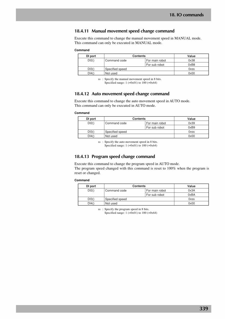
339
2
18. IO commands
18.4.11 Manual movement speed change command
Execute this command to change the manual movement speed in MANUAL mode.This command can only be executed in MANUAL mode.
Command
Contents Value0x380xB80xss0x00
DI portDI2()
DI3()DI4()
Command code
Specified speedNot used
For main robot For sub robot
ss : Specify the manual movement speed in 8 bits.Specified range: 1 (=0x01) to 100 (=0x64)
18.4.12 Auto movement speed change command
Execute this command to change the auto movement speed in AUTO mode.This command can only be executed in AUTO mode.
Command
Contents Value0x390xB90xss0x00
DI portDI2()
DI3()DI4()
Command code
Specified speedNot used
For main robot For sub robot
ss : Specify the auto movement speed in 8 bits.Specified range: 1 (=0x01) to 100 (=0x64)
18.4.13 Program speed change command
Execute this command to change the program speed in AUTO mode.The program speed changed with this command is reset to 100% when the program isreset or changed.
Command
Contents Value0x3A0xBA0xss0x00
DI portDI2()
DI3()DI4()
Command code
Specified speedNot used
For main robot For sub robot
ss : Specify the program speed in 8 bits.Specified range: 1 (=0x01) to 100 (=0x64)
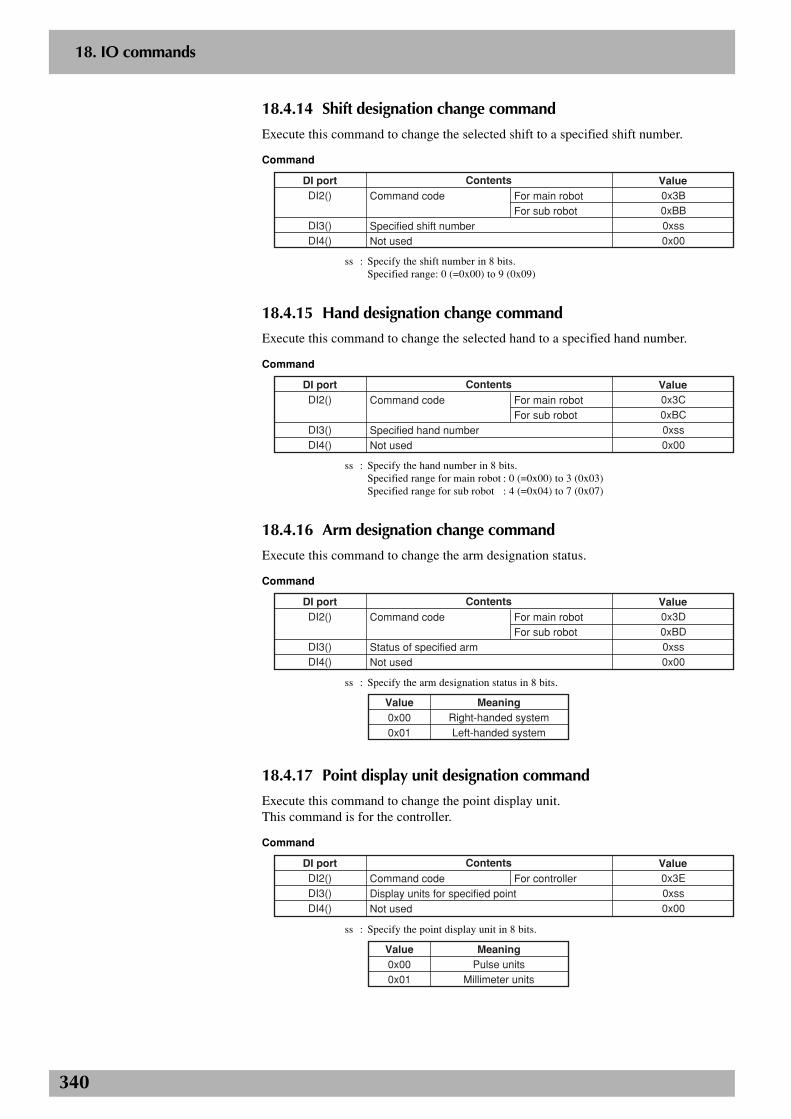
340
2
18. IO commands
18.4.14 Shift designation change command
Execute this command to change the selected shift to a specified shift number.
Command
Contents Value0x3B0xBB0xss0x00
DI portDI2()
DI3()DI4()
Command code
Specified shift numberNot used
For main robot For sub robot
ss : Specify the shift number in 8 bits.Specified range: 0 (=0x00) to 9 (0x09)
18.4.15 Hand designation change command
Execute this command to change the selected hand to a specified hand number.
Command
Contents Value0x3C0xBC0xss0x00
DI portDI2()
DI3()DI4()
Command code
Specified hand numberNot used
For main robot For sub robot
ss : Specify the hand number in 8 bits.Specified range for main robot : 0 (=0x00) to 3 (0x03)Specified range for sub robot : 4 (=0x04) to 7 (0x07)
18.4.16 Arm designation change command
Execute this command to change the arm designation status.
Command
Contents Value0x3D0xBD0xss0x00
DI portDI2()
DI3()DI4()
Command code
Status of specified armNot used
For main robot For sub robot
ss : Specify the arm designation status in 8 bits.
Value0x000x01
MeaningRight-handed systemLeft-handed system
18.4.17 Point display unit designation command
Execute this command to change the point display unit.This command is for the controller.
Command
Contents Value0x3E0xss0x00
DI portDI2()DI3()DI4()
Command codeDisplay units for specified pointNot used
For controller
ss : Specify the point display unit in 8 bits.
Value0x000x01
MeaningPulse units
Millimeter units
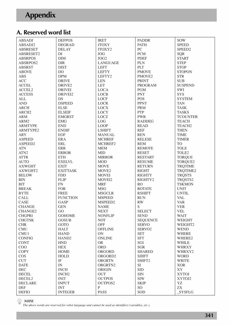
341
ABSADJABSADJ2ABSRESETABSRESET2ABSRPOSABSRPOS2ABSRSTABOVEABSACCACCELACCEL2ACCESSALLANDARCHARCH2ARMARM2ARMTYPEARMTYPE2ARYASPEEDASPEED2ATNATN2ATTRAUTOAXWGHTAXWGHT2BELOWBINBITBREAKBYTECALLCASECHANGECHANGE2CHGPRICHGTSKCHRCMUCMU1CONFIGCONTCOOCOPYCOSCUTDATEDECDECELDECEL2DECLAREDEFDEFIO
DEFPOSDEGRADDELAYDIDIMDIRDISTDODPMDRIVEDRIVE2DRIVEIDRIVEI2DSDSPEEDELSEELSEIFEMGRSTEMGENDENDIFEOFERAERLERRERRORETHEXELVLEXITEXITTASKFDDFLIPFNFORFREEFUNCTIONGASPGENGOGOHOMEGOSUBGOTOHALTHANDHAND2HNDHEXHOMEHOLDIFININCHINCH2INITINPUTINTINTEGER
IRETJTOXYJTOXY2JOGJOG2LANGUAGELEFTLEFTYLEFTY2LENLETLOCALOCBLOCFLOCRLOCXLOCYLOCZLOGLOOPLSHIFTMANUALMCHREFMCHREF2MEMMIDMIRRORMODMOVEMOVE2MOVEIMOVEI2MRFMSGMSGCLRMSPEEDMSPEED2NAMENEXTNONFLIPNOTOFFOFFLINEONONLINEORORDORGORDORGORD2ORGRTNORGRTN2ORIGINOUTOUTPOSOUTPOS2PPASS
PADDRPATHPCPCMPDEFPLNPLTPMOVEPMOVE2PRINTPROGRAMPGMPNTPOSPPNTPRMPTPPWRRADDEGREADREFRENRELESEREMREMOTERESETRESTARTRESUMERETURNRIGHTRIGHTYRIGHTY2ROROTATERSHIFTRUNRWSSELECTSENDSEQUENCESERVOSERVO2SETSFTSGISGRSHAREDSHIFTSHIFT2SISIDSINSIWSKIPSOSOD
SOWSPEEDSPEED2SQRSTARTSTEPSTOPSTOPONSTRSUBSUSPENDSWISYSSYSTEMTANTASKTASKSTCOUNTERTEACHTEACH2THENTIMETIMERTOTOLETOLE2TORQUETORQUE2TRQTIMETRQTIME2TRQSTSTRQSTS2TSKMONUNITUNTILVALVARVERVELWAITWEIGHTWEIGHT2WENDWHEREWHERE2WHILEWHRXYWHRXY2WORDWRITEXORXYXYTOJXYTOJ2YZZX_SYSFLG
Appendix
A. Reserved word list
n NOTEThe above words are reserved for robot language and cannot be used as identifiers (variables, etc.).
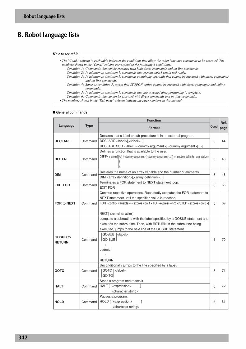
342
Robot language lists
B. Robot language lists
How to see table
• The "Cond." column in each table indicates the conditions that allow the robot language commands to be executed. Thenumbers shown in the "Cond." column correspond to the following 6 conditions.
Condition 1: Commands that can be executed with both direct commands and on-line commands.Condition 2: In addition to condition 1, commands that execute task 1 (main task) only.Condition 3: In addition to condition 1, commands containing operands that cannot be executed with direct commands
and on-line commands.Condition 4: Same as condition 5, except that STOPON option cannot be executed with direct commands and online
commands.Condition 5: In addition to condition 1, commands that are executed after positioning is complete.Condition 6: Commands that cannot be executed with direct commands and on-line commands.
• The numbers shown in the "Ref. page" column indicate the page numbers in this manual.
■ General commands
Language
DECLARE
DEF FN
DIM
EXIT FOR
FOR to NEXT
GOSUB to
RETURN
GOTO
HALT
HOLD
Type
Command
Command
Command
Command
Command
Command
Command
Command
Command
Function
Format
Declares that a label or sub-procedure is in an external program.
DECLARE <label>[,<label>...]
DECLARE SUB <label>[(<dummy argument>[,<dummy argument>]...)]
Defines a function that is available to the user.
Declares the name of an array variable and the number of elements.
DIM <array definition>[,<array definition>,...]
Terminates a FOR statement to NEXT statement loop.
EXIT FOR
Controls repetitive operations. Repeatedly executes the FOR statement to
NEXT statement until the specified value is reached.
Jumps to a subroutine with the label specified by a GOSUB statement and
executes the subroutine. Then, with RETURN in the subroutine being
executed, jumps to the next line of the GOSUB statement.
Unconditionally jumps to the line specified by a label.
Stops a program and resets it.
Pauses a program.
Cond.
6
6
6
6
6
6
6
6
6
Ref.
page
44
46
48
66
69
70
71
72
81
DEF FN<name>[ % ] [(<dummy argument>[,<dummy argument>...])] =<function definition expression>
!
$
FOR <control variable>=<expression 1> TO <expression 2> [STEP <expression 3>]
:
NEXT [<control variable>]
GOTO <label>
GO TO
HALT [ <expression> ]
<character string>
GOSUB <label>
GO SUB
:
<label>:
:
RETURN
HOLD [ <expression> ]
<character string>
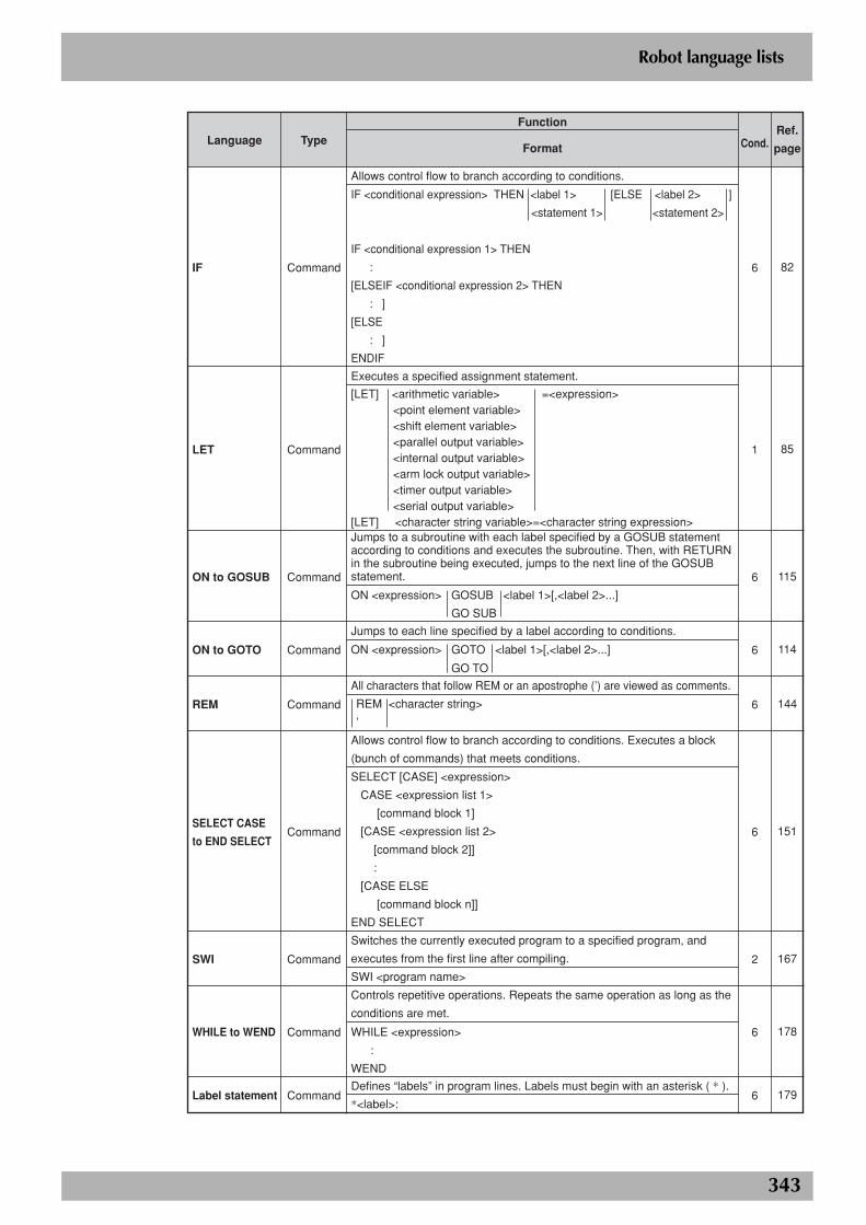
343
Robot language lists
Language
IF
LET
ON to GOSUB
ON to GOTO
REM
SELECT CASE
to END SELECT
SWI
WHILE to WEND
Label statement
Type
Command
Command
Command
Command
Command
Command
Command
Command
Command
Function
Format
Allows control flow to branch according to conditions.
Executes a specified assignment statement.
Jumps to a subroutine with each label specified by a GOSUB statement according to conditions and executes the subroutine. Then, with RETURN in the subroutine being executed, jumps to the next line of the GOSUB statement.
Jumps to each line specified by a label according to conditions.
All characters that follow REM or an apostrophe (’) are viewed as comments.
Allows control flow to branch according to conditions. Executes a block
(bunch of commands) that meets conditions.
Switches the currently executed program to a specified program, and
executes from the first line after compiling.
SWI <program name>
Controls repetitive operations. Repeats the same operation as long as the
conditions are met.
Defines “labels” in program lines. Labels must begin with an asterisk ( * ).
*<label>:
Cond.
6
1
6
6
6
6
2
6
6
Ref.
page
82
85
115
114
144
151
167
178
179
IF <conditional expression> THEN <label 1> [ELSE <label 2> ]
<statement 1> <statement 2>
IF <conditional expression 1> THEN
:
[ELSEIF <conditional expression 2> THEN
: ]
[ELSE
: ]
ENDIF
[LET] <arithmetic variable> =<expression> <point element variable> <shift element variable> <parallel output variable> <internal output variable> <arm lock output variable> <timer output variable> <serial output variable>[LET] <character string variable>=<character string expression>
ON <expression> GOSUB <label 1>[,<label 2>...]
GO SUB
ON <expression> GOTO <label 1>[,<label 2>...]
GO TO
WHILE <expression>
:
WEND
SELECT [CASE] <expression>
CASE <expression list 1>
[command block 1]
[CASE <expression list 2>
[command block 2]]
:
[CASE ELSE
[command block n]]
END SELECT
REM <character string>
’
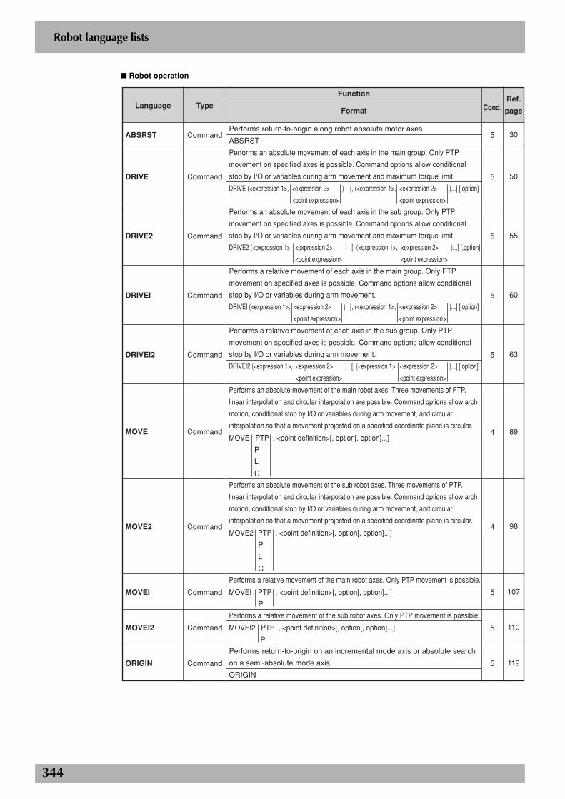
344
Robot language lists
■ Robot operation
Language
ABSRST
DRIVE
DRIVE2
DRIVEI
DRIVEI2
MOVE
MOVE2
MOVEI
MOVEI2
ORIGIN
Type
Command
Command
Command
Command
Command
Command
Command
Command
Command
Command
Function
Format
Performs return-to-origin along robot absolute motor axes.
ABSRST
Performs an absolute movement of each axis in the main group. Only PTP
movement on specified axes is possible. Command options allow conditional
stop by I/O or variables during arm movement and maximum torque limit.
Performs an absolute movement of each axis in the sub group. Only PTP
movement on specified axes is possible. Command options allow conditional
stop by I/O or variables during arm movement and maximum torque limit.
Performs a relative movement of each axis in the main group. Only PTP
movement on specified axes is possible. Command options allow conditional
stop by I/O or variables during arm movement.
Performs a relative movement of each axis in the sub group. Only PTP
movement on specified axes is possible. Command options allow conditional
stop by I/O or variables during arm movement.
Performs an absolute movement of the main robot axes. Three movements of PTP,
linear interpolation and circular interpolation are possible. Command options allow arch
motion, conditional stop by I/O or variables during arm movement, and circular
interpolation so that a movement projected on a specified coordinate plane is circular.
Performs an absolute movement of the sub robot axes. Three movements of PTP,
linear interpolation and circular interpolation are possible. Command options allow arch
motion, conditional stop by I/O or variables during arm movement, and circular
interpolation so that a movement projected on a specified coordinate plane is circular.
Performs a relative movement of the main robot axes. Only PTP movement is possible.
Performs a relative movement of the sub robot axes. Only PTP movement is possible.
Performs return-to-origin on an incremental mode axis or absolute search
on a semi-absolute mode axis.
ORIGIN
Cond.
5
5
5
5
5
4
4
5
5
5
Ref.
page
30
50
55
60
63
89
98
107
110
119
DRIVE (<expression 1>, <expression 2> ) [, (<expression 1>, <expression 2> )...] [,option]
<point expression> <point expression>
DRIVE2 (<expression 1>, <expression 2> ) [, (<expression 1>, <expression 2> )...] [,option]
<point expression> <point expression>
MOVE PTP , <point definition>[, option[, option]...]
P
L
C
MOVE2 PTP , <point definition>[, option[, option]...]
P
L
C
MOVEI PTP , <point definition>[, option[, option]...]
P
MOVEI2 PTP , <point definition>[, option[, option]...]
P
DRIVEI (<expression 1>, <expression 2> ) [, (<expression 1>, <expression 2> )...] [,option]
<point expression> <point expression>
DRIVEI2 (<expression 1>, <expression 2> ) [, (<expression 1>, <expression 2> )...] [,option]
<point expression> <point expression>
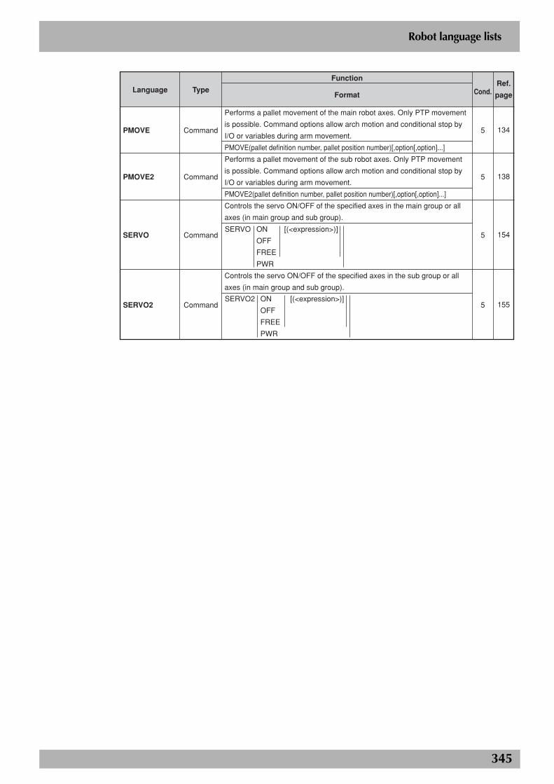
345
Robot language lists
Language
PMOVE
PMOVE2
SERVO
SERVO2
Type
Command
Command
Command
Command
Function
Format
Performs a pallet movement of the main robot axes. Only PTP movement
is possible. Command options allow arch motion and conditional stop by
I/O or variables during arm movement.
PMOVE(pallet definition number, pallet position number)[,option[,option]...]
Performs a pallet movement of the sub robot axes. Only PTP movement
is possible. Command options allow arch motion and conditional stop by
I/O or variables during arm movement.
PMOVE2(pallet definition number, pallet position number)[,option[,option]...]
Controls the servo ON/OFF of the specified axes in the main group or all
axes (in main group and sub group).
Controls the servo ON/OFF of the specified axes in the sub group or all
axes (in main group and sub group).
Cond.
5
5
5
5
Ref.
page
134
138
154
155
SERVO ON [(<expression>)]
OFF
FREE
PWR
SERVO2 ON [(<expression>)]
OFF
FREE
PWR
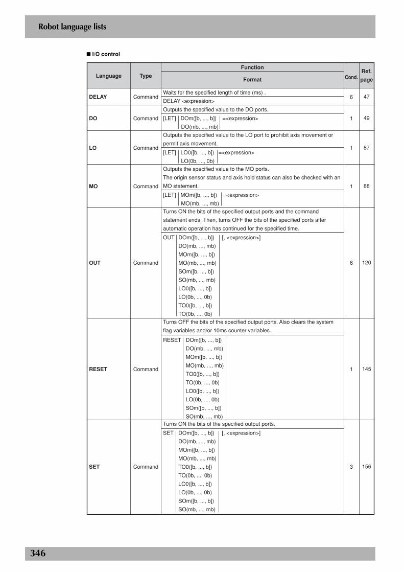
346
Robot language lists
■ I/O control
Language
DELAY
DO
LO
MO
OUT
RESET
SET
Type
Command
Command
Command
Command
Command
Command
Command
Function
Format
Waits for the specified length of time (ms) .
DELAY <expression>
Outputs the specified value to the DO ports.
Outputs the specified value to the LO port to prohibit axis movement or
permit axis movement.
Outputs the specified value to the MO ports.
The origin sensor status and axis hold status can also be checked with an
MO statement.
Turns ON the bits of the specified output ports and the command
statement ends. Then, turns OFF the bits of the specified ports after
automatic operation has continued for the specified time.
Turns OFF the bits of the specified output ports. Also clears the system
flag variables and/or 10ms counter variables.
Turns ON the bits of the specified output ports.
Cond.
6
1
1
1
6
1
3
Ref.
page
47
49
87
88
120
145
156
[LET] DOm([b, ..., b]) =<expression>
DO(mb, ..., mb)
[LET] LO0([b, ..., b]) =<expression>
LO(0b, ..., 0b)
[LET] MOm([b, ..., b]) =<expression>
MO(mb, ..., mb)
RESET DOm([b, ..., b])
DO(mb, ..., mb)
MOm([b, ..., b])
MO(mb, ..., mb)
TO0([b, ..., b])
TO(0b, ..., 0b)
LO0([b, ..., b])
LO(0b, ..., 0b)
SOm([b, ..., b])
SO(mb, ..., mb)
OUT DOm([b, ..., b]) [, <expression>]
DO(mb, ..., mb)
MOm([b, ..., b])
MO(mb, ..., mb)
SOm([b, ..., b])
SO(mb, ..., mb)
LO0([b, ..., b])
LO(0b, ..., 0b)
TO0([b, ..., b])
TO(0b, ..., 0b)
SET DOm([b, ..., b]) [, <expression>]
DO(mb, ..., mb)
MOm([b, ..., b])
MO(mb, ..., mb)
TO0([b, ..., b])
TO(0b, ..., 0b)
LO0([b, ..., b])
LO(0b, ..., 0b)
SOm([b, ..., b])
SO(mb, ..., mb)
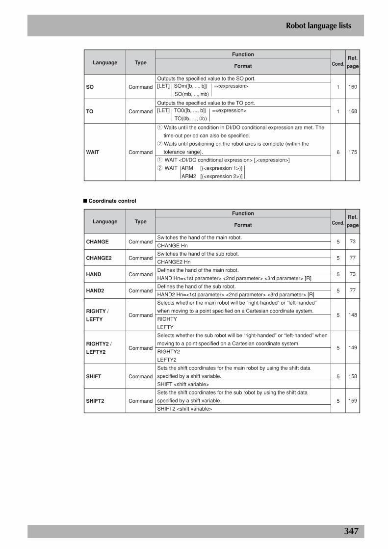
347
Robot language lists
Language
SO
TO
WAIT
Type
Command
Command
Command
Function
Format
Outputs the specified value to the SO port.
Outputs the specified value to the TO port.
q Waits until the condition in DI/DO conditional expression are met. The
time-out period can also be specified.
w Waits until positioning on the robot axes is complete (within the
tolerance range).
Cond.
1
1
6
Ref.
page
160
168
175
[LET] SOm([b, ..., b]) =<expression>
SO(mb, ..., mb)
[LET] TO0([b, ..., b]) =<expression>
TO(0b, ..., 0b)
q WAIT <DI/DO conditional expression> [,<expression>]
w WAIT ARM [(<expression 1>)]
ARM2 [(<expression 2>)]
■ Coordinate control
Language
CHANGE
CHANGE2
HAND
HAND2
RIGHTY /
LEFTY
RIGHTY2 /
LEFTY2
SHIFT
SHIFT2
Type
Command
Command
Command
Command
Command
Command
Command
Command
Function
Format
Switches the hand of the main robot.
CHANGE Hn
Switches the hand of the sub robot.
CHANGE2 Hn
Defines the hand of the main robot.
HAND Hn=<1st parameter> <2nd parameter> <3rd parameter> [R]
Defines the hand of the sub robot.
HAND2 Hn=<1st parameter> <2nd parameter> <3rd parameter> [R]
Selects whether the main robot will be “right-handed” or “left-handed”
when moving to a point specified on a Cartesian coordinate system.
RIGHTY
LEFTY
Selects whether the sub robot will be “right-handed” or “left-handed” when
moving to a point specified on a Cartesian coordinate system.
RIGHTY2
LEFTY2
Sets the shift coordinates for the main robot by using the shift data
specified by a shift variable.
SHIFT <shift variable>
Sets the shift coordinates for the sub robot by using the shift data
specified by a shift variable.
SHIFT2 <shift variable>
Cond.
5
5
5
5
5
5
5
5
Ref.
page
73
77
73
77
148
149
158
159
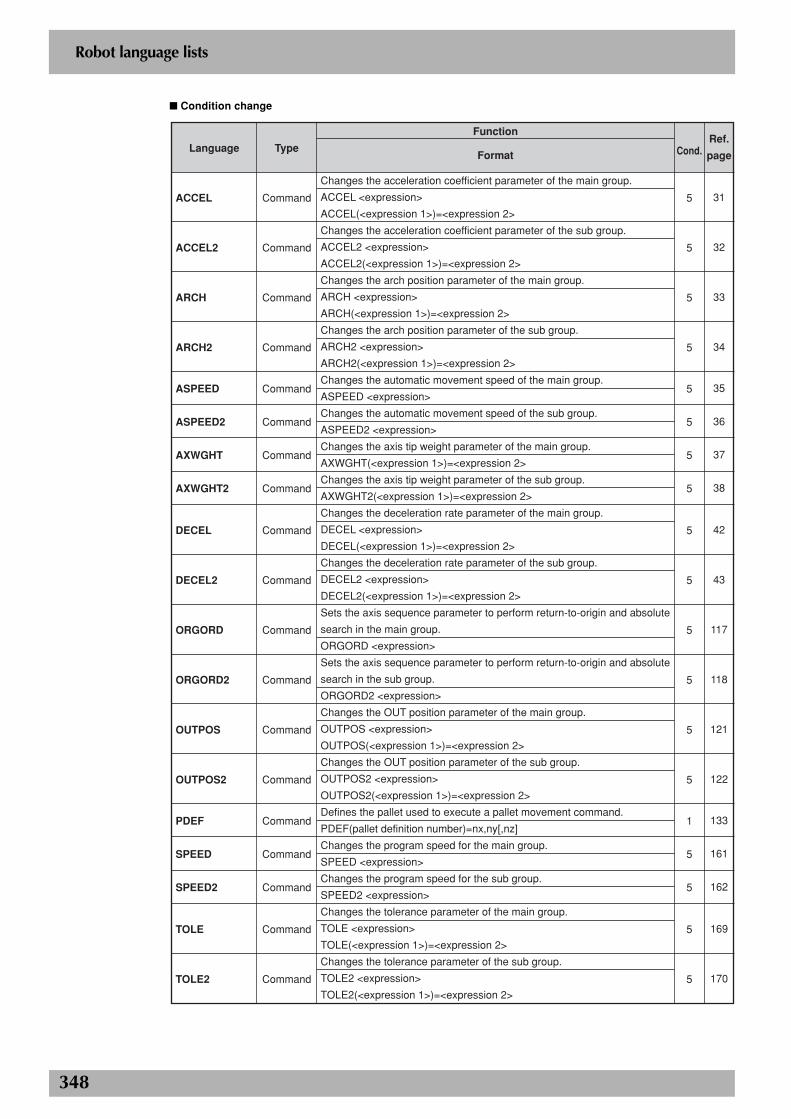
348
Robot language lists
■ Condition change
Language
ACCEL
ACCEL2
ARCH
ARCH2
ASPEED
ASPEED2
AXWGHT
AXWGHT2
DECEL
DECEL2
ORGORD
ORGORD2
OUTPOS
OUTPOS2
PDEF
SPEED
SPEED2
TOLE
TOLE2
Type
Command
Command
Command
Command
Command
Command
Command
Command
Command
Command
Command
Command
Command
Command
Command
Command
Command
Command
Command
Function
Format
Changes the acceleration coefficient parameter of the main group.
ACCEL <expression>
ACCEL(<expression 1>)=<expression 2>
Changes the acceleration coefficient parameter of the sub group.
ACCEL2 <expression>
ACCEL2(<expression 1>)=<expression 2>
Changes the arch position parameter of the main group.
ARCH <expression>
ARCH(<expression 1>)=<expression 2>
Changes the arch position parameter of the sub group.
ARCH2 <expression>
ARCH2(<expression 1>)=<expression 2>
Changes the automatic movement speed of the main group.
ASPEED <expression>
Changes the automatic movement speed of the sub group.
ASPEED2 <expression>
Changes the axis tip weight parameter of the main group.
AXWGHT(<expression 1>)=<expression 2>
Changes the axis tip weight parameter of the sub group.
AXWGHT2(<expression 1>)=<expression 2>
Changes the deceleration rate parameter of the main group.
DECEL <expression>
DECEL(<expression 1>)=<expression 2>
Changes the deceleration rate parameter of the sub group.
DECEL2 <expression>
DECEL2(<expression 1>)=<expression 2>
Sets the axis sequence parameter to perform return-to-origin and absolute
search in the main group.
ORGORD <expression>
Sets the axis sequence parameter to perform return-to-origin and absolute
search in the sub group.
ORGORD2 <expression>
Changes the OUT position parameter of the main group.
OUTPOS <expression>
OUTPOS(<expression 1>)=<expression 2>
Changes the OUT position parameter of the sub group.
OUTPOS2 <expression>
OUTPOS2(<expression 1>)=<expression 2>
Defines the pallet used to execute a pallet movement command.
PDEF(pallet definition number)=nx,ny[,nz]
Changes the program speed for the main group.
SPEED <expression>
Changes the program speed for the sub group.
SPEED2 <expression>
Changes the tolerance parameter of the main group.
TOLE <expression>
TOLE(<expression 1>)=<expression 2>
Changes the tolerance parameter of the sub group.
TOLE2 <expression>
TOLE2(<expression 1>)=<expression 2>
Cond.
5
5
5
5
5
5
5
5
5
5
5
5
5
5
1
5
5
5
5
Ref.
page
31
32
33
34
35
36
37
38
42
43
117
118
121
122
133
161
162
169
170
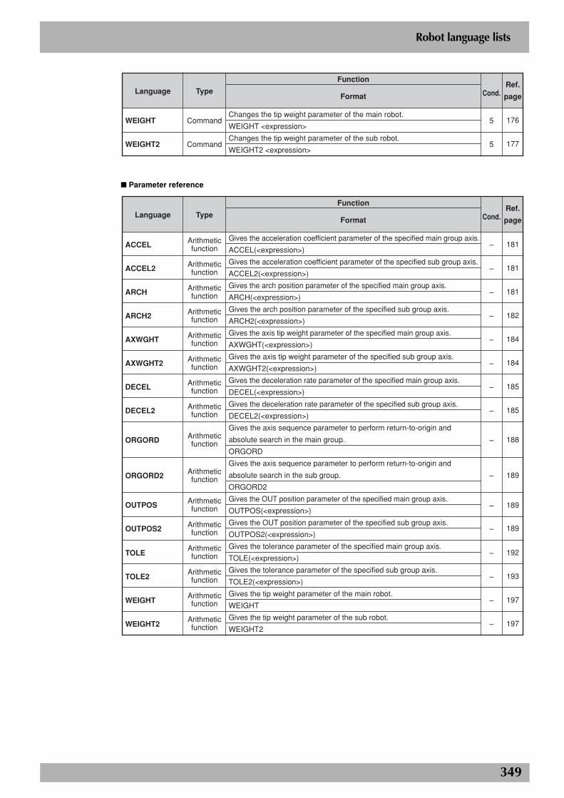
349
Robot language lists
Language
WEIGHT
WEIGHT2
Type
Command
Command
Function
Format
Changes the tip weight parameter of the main robot.
WEIGHT <expression>
Changes the tip weight parameter of the sub robot.
WEIGHT2 <expression>
Cond.
5
5
Ref.
page
176
177
■ Parameter reference
Language
ACCEL
ACCEL2
ARCH
ARCH2
AXWGHT
AXWGHT2
DECEL
DECEL2
ORGORD
ORGORD2
OUTPOS
OUTPOS2
TOLE
TOLE2
WEIGHT
WEIGHT2
Type
Arithmetic function
Arithmetic function
Arithmetic function
Arithmetic function
Arithmetic function
Arithmetic function
Arithmetic function
Arithmetic function
Arithmetic function
Arithmetic function
Arithmetic function
Arithmetic function
Arithmetic function
Arithmetic function
Arithmetic function
Arithmetic function
Function
Format
Gives the acceleration coefficient parameter of the specified main group axis.
ACCEL(<expression>)
Gives the acceleration coefficient parameter of the specified sub group axis.
ACCEL2(<expression>)
Gives the arch position parameter of the specified main group axis.
ARCH(<expression>)
Gives the arch position parameter of the specified sub group axis.
ARCH2(<expression>)
Gives the axis tip weight parameter of the specified main group axis.
AXWGHT(<expression>)
Gives the axis tip weight parameter of the specified sub group axis.
AXWGHT2(<expression>)
Gives the deceleration rate parameter of the specified main group axis.
DECEL(<expression>)
Gives the deceleration rate parameter of the specified sub group axis.
DECEL2(<expression>)
Gives the axis sequence parameter to perform return-to-origin and
absolute search in the main group.
ORGORD
Gives the axis sequence parameter to perform return-to-origin and
absolute search in the sub group.
ORGORD2
Gives the OUT position parameter of the specified main group axis.
OUTPOS(<expression>)
Gives the OUT position parameter of the specified sub group axis.
OUTPOS2(<expression>)
Gives the tolerance parameter of the specified main group axis.
TOLE(<expression>)
Gives the tolerance parameter of the specified sub group axis.
TOLE2(<expression>)
Gives the tip weight parameter of the main robot.
WEIGHT
Gives the tip weight parameter of the sub robot.
WEIGHT2
Cond.
–
–
–
–
–
–
–
–
–
–
–
–
–
–
–
–
Ref.
page
181
181
181
182
184
184
185
185
188
189
189
189
192
193
197
197
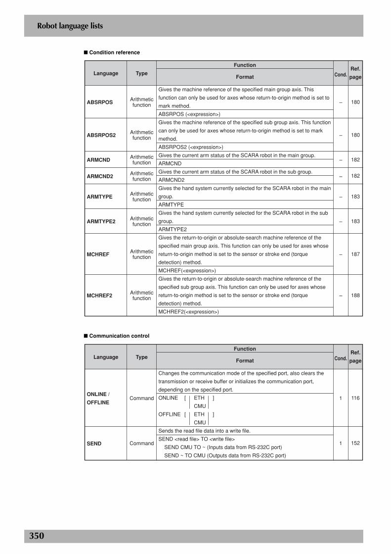
350
Robot language lists
■ Condition reference
Language
ABSRPOS
ABSRPOS2
ARMCND
ARMCND2
ARMTYPE
ARMTYPE2
MCHREF
MCHREF2
Type
Arithmetic function
Arithmetic function
Arithmetic function
Arithmetic function
Arithmetic function
Arithmetic function
Arithmetic function
Arithmetic function
Function
Format
Gives the machine reference of the specified main group axis. This
function can only be used for axes whose return-to-origin method is set to
mark method.
ABSRPOS (<expression>)
Gives the machine reference of the specified sub group axis. This function
can only be used for axes whose return-to-origin method is set to mark
method.
ABSRPOS2 (<expression>)
Gives the current arm status of the SCARA robot in the main group.
ARMCND
Gives the current arm status of the SCARA robot in the sub group.
ARMCND2
Gives the hand system currently selected for the SCARA robot in the main
group.
ARMTYPE
Gives the hand system currently selected for the SCARA robot in the sub
group.
ARMTYPE2
Gives the return-to-origin or absolute-search machine reference of the
specified main group axis. This function can only be used for axes whose
return-to-origin method is set to the sensor or stroke end (torque
detection) method.
MCHREF(<expression>)
Gives the return-to-origin or absolute-search machine reference of the
specified sub group axis. This function can only be used for axes whose
return-to-origin method is set to the sensor or stroke end (torque
detection) method.
MCHREF2(<expression>)
Cond.
–
–
–
–
–
–
–
–
Ref.
page
180
180
182
182
183
183
187
188
■ Communication control
Language
ONLINE /
OFFLINE
SEND
Type
Command
Command
Function
Format
Changes the communication mode of the specified port, also clears the
transmission or receive buffer or initializes the communication port,
depending on the specified port.
ONLINE [ ETH ]
CMU
OFFLINE [ ETH ]
CMU
Sends the read file data into a write file.
SEND <read file> TO <write file>
SEND CMU TO ~ (Inputs data from RS-232C port)
SEND ~ TO CMU (Outputs data from RS-232C port)
Cond.
1
1
Ref.
page
116
152
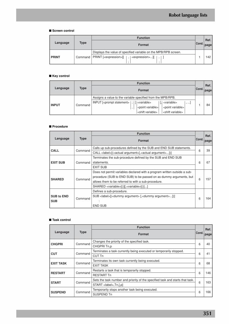
351
Robot language lists
■ Screen control
Language
Type
Command
Function
Format
Displays the value of specified variable on the MPB/RPB screen.
Cond.
1
Ref.
page
142PRINT [<expression>][ , <expression>...][ , ]
; ;
■ Key control
Language
INPUT
Type
Command
Function
Format
Assigns a value to the variable specified from the MPB/RPB.
Cond.
1
Ref.
page
84INPUT [<prompt statement> ; ] <variable> [, <variable> , ...]
, <point variable> <point variable>
<shift variable> <shift variable>
■ Procedure
Language
CALL
EXIT SUB
SHARED
SUB to END
SUB
Type
Command
Command
Command
Command
Function
Format
Calls up sub-procedures defined by the SUB and END SUB statements.
CALL <label>[(<actual argument>[,<actual argument>...])]
Terminates the sub-procedure defined by the SUB and END SUB
statements.
EXIT SUB
Does not permit variables declared with a program written outside a sub-
procedure (SUB to END SUB) to be passed on as dummy arguments, but
allows them to be referred to with a sub-procedure.
SHARED <variable>[()][,<variable>[()]...]
Defines a sub-procedure.
Cond.
6
6
6
6
Ref.
page
39
67
157
164SUB <label>[(<dummy argument> [,<dummy argument>...])]
:
END SUB
■ Task control
Language
CHGPRI
CUT
EXIT TASK
RESTART
START
SUSPEND
Type
Command
Command
Command
Command
Command
Command
Function
Format
Changes the priority of the specified task.
CHGPRI Tn,p
Terminates a task currently being executed or temporarily stopped.
CUT Tn
Terminates its own task currently being executed.
EXIT TASK
Restarts a task that is temporarily stopped.
RESTART Tn
Sets the task number and priority of the specified task and starts that task.
START <label>,Tn,[,p]
Temporarily stops another task being executed.
SUSPEND Tn
Cond.
6
6
6
6
6
6
Ref.
page
40
41
68
146
163
166
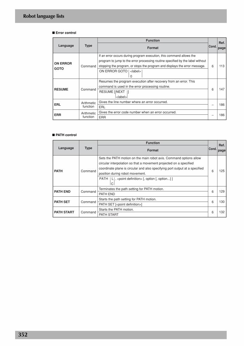
352
Robot language lists
■ Error control
Language
ON ERROR
GOTO
RESUME
ERL
ERR
Type
Command
Command
Arithmetic function
Arithmetic function
Function
Format
If an error occurs during program execution, this command allows the
program to jump to the error processing routine specified by the label without
stopping the program, or stops the program and displays the error message.
Resumes the program execution after recovery from an error. This
command is used in the error processing routine.
Gives the line number where an error occurred.
ERL
Gives the error code number when an error occurred.
ERR
Cond.
6
6
–
–
Ref.
page
113
147
186
186
ON ERROR GOTO <label>
0
RESUME [ NEXT ]
<label>
■ PATH control
Language
PATH
PATH END
PATH SET
PATH START
Type
Command
Command
Command
Command
Function
Format
Sets the PATH motion on the main robot axis. Command options allow
circular interpolation so that a movement projected on a specified
coordinate plane is circular and also specifying port output at a specified
position during robot movement.
Terminates the path setting for PATH motion.
PATH END
Starts the path setting for PATH motion.
PATH SET [<point definition>]
Starts the PATH motion.
PATH START
Cond.
6
6
6
6
Ref.
page
125
129
130
132
PATH L , <point definition> [, option [, option...] ]
C
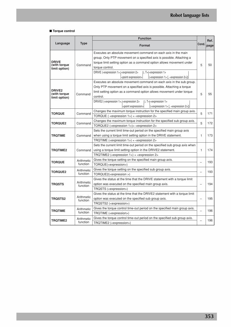
353
Robot language lists
■ Torque control
Language
DRIVE(with torque limit option)
DRIVE2(with torque limit option)
TORQUE
TORQUE2
TRQTIME
TRQTIME2
TORQUE
TORQUE2
TRQSTS
TRQSTS2
TRQTIME
TRQTIME2
Type
Command
Command
Command
Command
Command
Command
Arithmetic function
Arithmetic function
Arithmetic function
Arithmetic function
Arithmetic function
Arithmetic function
Function
Format
Executes an absolute movement command on each axis in the main
group. Only PTP movement on a specified axis is possible. Attaching a
torque limit setting option as a command option allows movement under
torque control.
Executes an absolute movement command on each axis in the sub group.
Only PTP movement on a specified axis is possible. Attaching a torque
limit setting option as a command option allows movement under torque
control.
Changes the maximum torque instruction for the specified main group axis.
TORQUE ( <expression 1>) = <expression 2>
Changes the maximum torque instruction for the specified sub group axis.
TORQUE2 (<expression 1>)= <expression 2>
Sets the current limit time-out period on the specified main group axis
when using a torque limit setting option in the DRIVE statement.
TRQTIME (<expression 1>) = <expression 2>
Sets the current limit time-out period on the specified sub group axis when
using a torque limit setting option in the DRIVE2 statement.
TRQTIME2 (<expression 1>) = <expression 2>
Gives the torque setting on the specified main group axis.
TORQUE(<expression>)
Gives the torque setting on the specified sub group axis.
TORQUE2(<expression >)
Gives the status at the time that the DRIVE statement with a torque limit
option was executed on the specified main group axis.
TRQSTS (<expression>)
Gives the status at the time that the DRIVE2 statement with a torque limit
option was executed on the specified sub group axis.
TRQSTS2 (<expression>)
Gives the torque control time-out period on the specified main group axis.
TRQTIME (<expression>)
Gives the torque control time-out period on the specified sub group axis.
TRQTIME2 (<expression>)
Cond.
5
5
5
5
1
1
–
–
–
–
–
–
Ref.
page
50
55
171
172
173
174
193
193
194
195
196
196
DRIVE (<expression 1>, <expression 2> ), T= <expression 1>
<point expression> (<expression 1> [, <expression 2>])
DRIVE2 (<expression 1>, <expression 2> ), T= <expression 1>
<point expression> (<expression 1> [, <expression 2>])
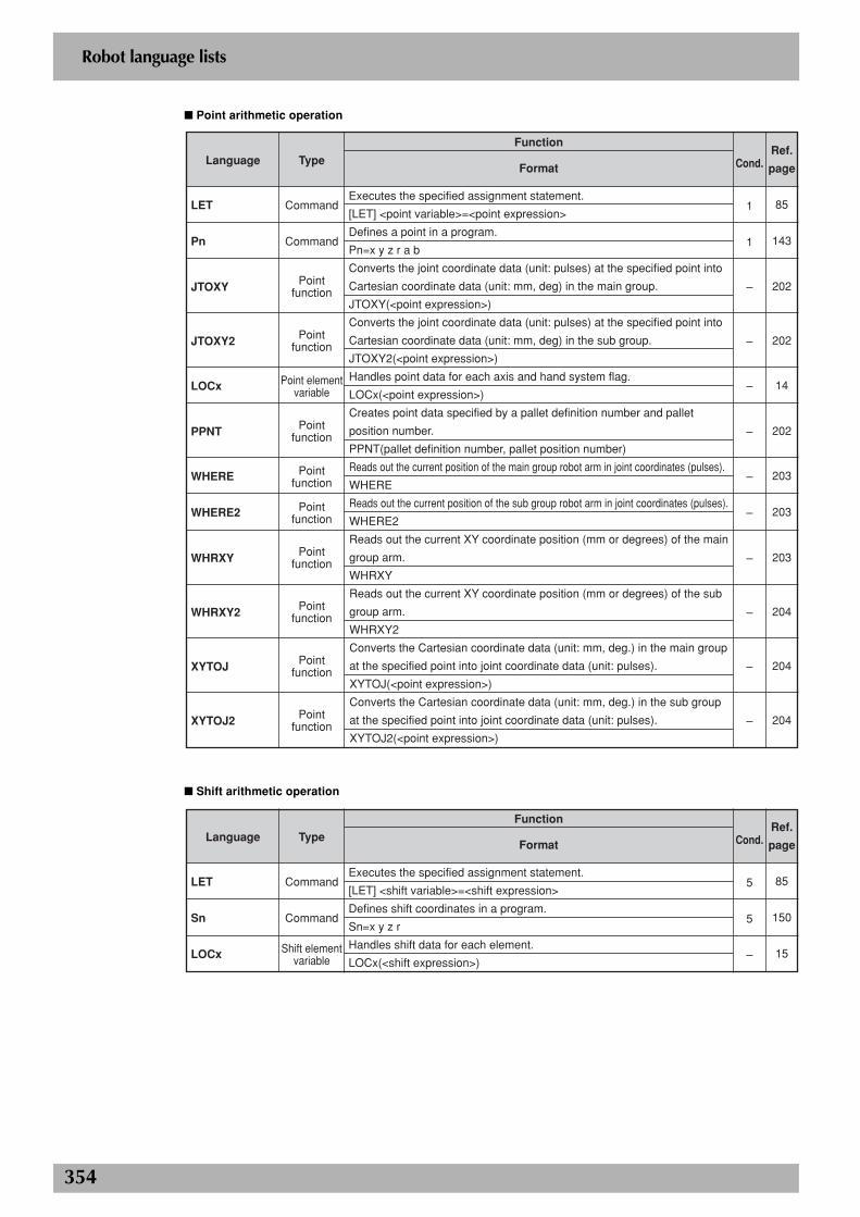
354
Robot language lists
■ Point arithmetic operation
Language
LET
Pn
JTOXY
JTOXY2
LOCx
PPNT
WHERE
WHERE2
WHRXY
WHRXY2
XYTOJ
XYTOJ2
Type
Command
Command
Point function
Point function
Point element variable
Point function
Point function
Point function
Point function
Point function
Point function
Point function
Function
Format
Executes the specified assignment statement.
[LET] <point variable>=<point expression>
Defines a point in a program.
Pn=x y z r a b
Converts the joint coordinate data (unit: pulses) at the specified point into
Cartesian coordinate data (unit: mm, deg) in the main group.
JTOXY(<point expression>)
Converts the joint coordinate data (unit: pulses) at the specified point into
Cartesian coordinate data (unit: mm, deg) in the sub group.
JTOXY2(<point expression>)
Handles point data for each axis and hand system flag.
LOCx(<point expression>)
Creates point data specified by a pallet definition number and pallet
position number.
PPNT(pallet definition number, pallet position number)
Reads out the current position of the main group robot arm in joint coordinates (pulses).
WHERE
Reads out the current position of the sub group robot arm in joint coordinates (pulses).
WHERE2
Reads out the current XY coordinate position (mm or degrees) of the main
group arm.
WHRXY
Reads out the current XY coordinate position (mm or degrees) of the sub
group arm.
WHRXY2
Converts the Cartesian coordinate data (unit: mm, deg.) in the main group
at the specified point into joint coordinate data (unit: pulses).
XYTOJ(<point expression>)
Converts the Cartesian coordinate data (unit: mm, deg.) in the sub group
at the specified point into joint coordinate data (unit: pulses).
XYTOJ2(<point expression>)
Cond.
1
1
–
–
–
–
–
–
–
–
–
–
Ref.
page
85
143
202
202
14
202
203
203
203
204
204
204
■ Shift arithmetic operation
Language
LET
Sn
LOCx
Type
Command
Command
Shift element variable
Function
Format
Executes the specified assignment statement.
[LET] <shift variable>=<shift expression>
Defines shift coordinates in a program.
Sn=x y z r
Handles shift data for each element.
LOCx(<shift expression>)
Cond.
5
5
–
Ref.
page
85
150
15
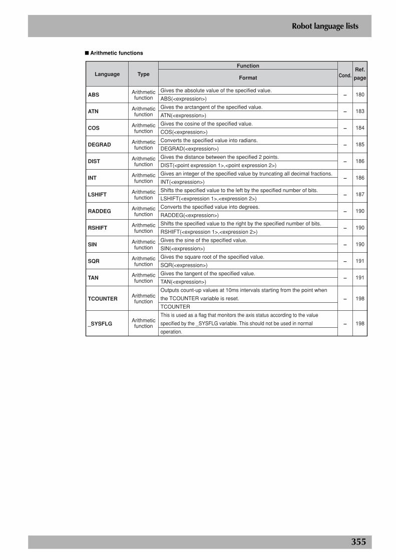
355
Robot language lists
■ Arithmetic functions
Language
ABS
ATN
COS
DEGRAD
DIST
INT
LSHIFT
RADDEG
RSHIFT
SIN
SQR
TAN
TCOUNTER
_SYSFLG
Type
Arithmetic function
Arithmetic function
Arithmetic function
Arithmetic function
Arithmetic function
Arithmetic function
Arithmetic function
Arithmetic function
Arithmetic function
Arithmetic function
Arithmetic function
Arithmetic function
Arithmetic function
Arithmetic function
Function
Format
Gives the absolute value of the specified value.
ABS(<expression>)
Gives the arctangent of the specified value.
ATN(<expression>)
Gives the cosine of the specified value.
COS(<expression>)
Converts the specified value into radians.
DEGRAD(<expression>)
Gives the distance between the specified 2 points.
DIST(<point expression 1>,<point expression 2>)
Gives an integer of the specified value by truncating all decimal fractions.
INT(<expression>)
Shifts the specified value to the left by the specified number of bits.
LSHIFT(<expression 1>,<expression 2>)
Converts the specified value into degrees.
RADDEG(<expression>)
Shifts the specified value to the right by the specified number of bits.
RSHIFT(<expression 1>,<expression 2>)
Gives the sine of the specified value.
SIN(<expression>)
Gives the square root of the specified value.
SQR(<expression>)
Gives the tangent of the specified value.
TAN(<expression>)
Outputs count-up values at 10ms intervals starting from the point when
the TCOUNTER variable is reset.
TCOUNTER
This is used as a flag that monitors the axis status according to the value
specified by the _SYSFLG variable. This should not be used in normal
operation.
Cond.
–
–
–
–
–
–
–
–
–
–
–
–
–
–
Ref.
page
180
183
184
185
186
186
187
190
190
190
191
191
198
198
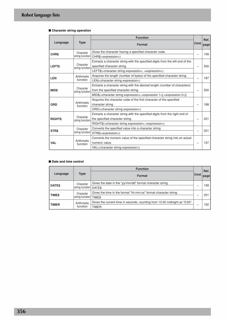
356
Robot language lists
■ Character string operation
Language
CHR$
LEFT$
LEN
MID$
ORD
RIGHT$
STR$
VAL
Type
Character string function
Character string function
Arithmetic function
Character string function
Arithmetic function
Character string function
Character string function
Arithmetic function
Function
Format
Gives the character having a specified character code.
CHR$(<expression>)
Extracts a character string with the specified digits from the left end of the
specified character string.
LEFT$(<character string expression>, <expression>)
Acquires the length (number of bytes) of the specified character string.
LEN(<character string expression>)
Extracts a character string with the desired length (number of characters)
from the specified character string.
MID$(<character string expression>,<expression 1>[,<expression 2>])
Acquires the character code of the first character of the specified
character string.
ORD(<character string expression>)
Extracts a character string with the specified digits from the right end of
the specified character string.
RIGHT$(<character string expression>,<expression>)
Converts the specified value into a character string.
STR$(<expression>)
Converts the numeric value of the specified character string into an actual
numeric value.
VAL(<character string expression>)
Cond.
–
–
–
–
–
–
–
–
Ref.
page
199
200
187
200
188
201
201
197
■ Date and time control
Language
DATE$
TIME$
TIMER
Type
Character string function
Character string function
Arithmetic function
Function
Format
Gives the date in the "yy/mm/dd" format character string.
DATE$
Gives the time in the format "hh:mm:ss" format character string.
TIME$
Gives the current time in seconds, counting from 12:00 midnight as "0:00".
TIMER
Cond.
–
–
–
Ref.
page
199
201
192
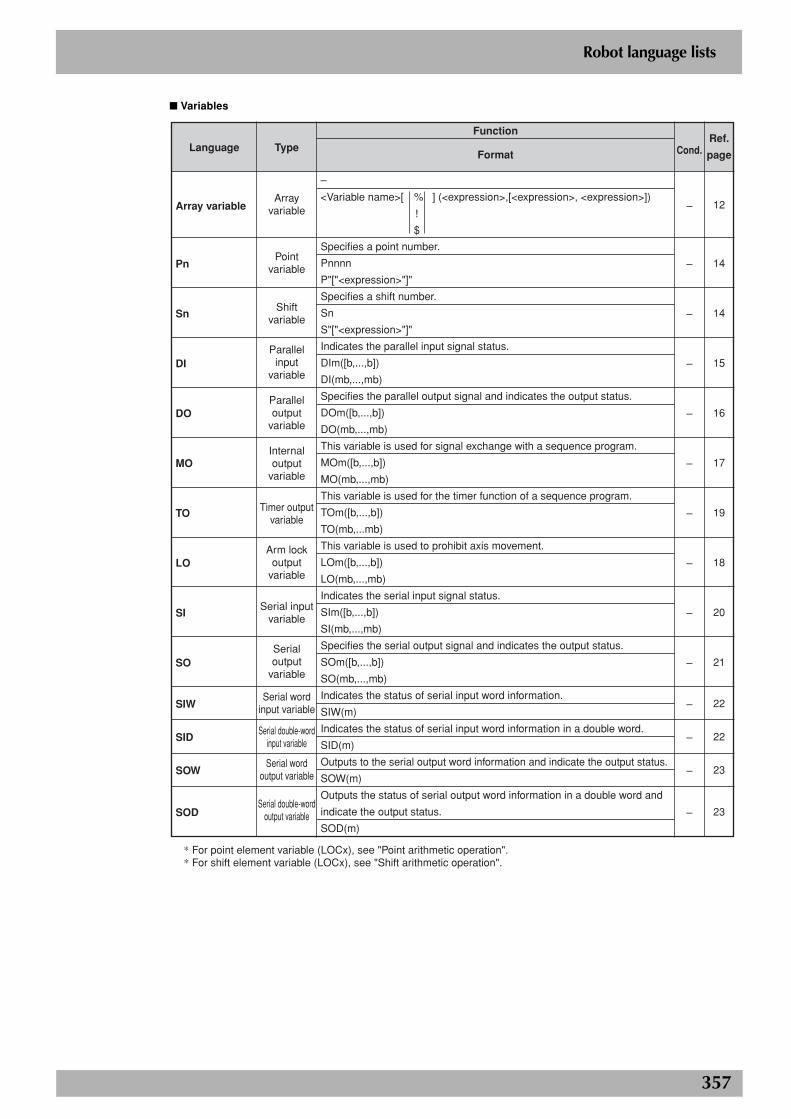
357
Robot language lists
■ Variables
Language
Array variable
Pn
Sn
DI
DO
MO
TO
LO
SI
SO
SIW
SID
SOW
SOD
Type
Array variable
Point variable
Shift variable
Parallel input
variable
Parallel output
variable
Internal output
variable
Timer output variable
Arm lock output
variable
Serial input variable
Serial output
variable
Serial word input variable
Serial double-word input variable
Serial word output variable
Serial double-word output variable
Function
Format
–
Specifies a point number.
Pnnnn
P"["<expression>"]"
Specifies a shift number.
Sn
S"["<expression>"]"
Indicates the parallel input signal status.
DIm([b,...,b])
DI(mb,...,mb)
Specifies the parallel output signal and indicates the output status.
DOm([b,...,b])
DO(mb,...,mb)
This variable is used for signal exchange with a sequence program.
MOm([b,...,b])
MO(mb,...,mb)
This variable is used for the timer function of a sequence program.
TOm([b,...,b])
TO(mb,...mb)
This variable is used to prohibit axis movement.
LOm([b,...,b])
LO(mb,...,mb)
Indicates the serial input signal status.
SIm([b,...,b])
SI(mb,...,mb)
Specifies the serial output signal and indicates the output status.
SOm([b,...,b])
SO(mb,...,mb)
Indicates the status of serial input word information.
SIW(m)
Indicates the status of serial input word information in a double word.
SID(m)
Outputs to the serial output word information and indicate the output status.
SOW(m)
Outputs the status of serial output word information in a double word and
indicate the output status.
SOD(m)
Cond.
–
–
–
–
–
–
–
–
–
–
–
–
–
–
Ref.
page
12
14
14
15
16
17
19
18
20
21
22
22
23
23
<Variable name>[ % ] (<expression>,[<expression>, <expression>])
!
$
* For point element variable (LOCx), see "Point arithmetic operation".* For shift element variable (LOCx), see "Shift arithmetic operation".

Robot Controller
Programming Manual
All rights reserved. No part of this publication may be reproduced in any form without the permission of YAMAHA MOTOR CO., LTD.Information furnished by YAMAHA in this manual is believed to be reliable. However, no responsibility is assumed for possible inaccuracies or omissions. If you find any part unclear in this manual, please contact YAMAHA or YAMAHA sales representatives.
© YAMAHA MOTOR CO., LTD. IM Operations
RCX seriesSep. 2010Ver. 2.11This manual is based on Ver. 3.12 of Japanese manual.
Revision record
Manual version Issue date Description
Ver. 2.08 Aug. 2009 CAUTION about the execution of the commands following the PTP or interpolation movement was added.
Ver. 2.09 Dec. 2009 The address and other information were added to the front cover.
Ver. 2.10 Aug. 2010 ETH and CMU options were added to the ONLINE/OFFLINE statements.
Ver. 2.11 Sep. 2010 Clerical error corrections.


![YAMAHA ROBOT CONTROLLER SUPPORTING ......YAMAHA ROBOT CONTROLLER SUPPORTING SOFTWARE E64-P-Ver. 1.13.0 POPCOM Contents: [1] Installation Guide [2] Backup current data from robot controller](https://img.pdfslide.us/doc/110x75/5f0b5fca7e708231d4303425/yamaha-robot-controller-supporting-yamaha-robot-controller-supporting-software.jpg)