Embed Size (px)
Citation preview

YAMAHA, MERCURY & MARINER
9.9 & 15 HP 1990-1998 For motors 1999-Present see below
TrollMaster is a precision throttle control designed to achieve the maximum in trolling speed accuracy. The memory feature included in this control will allow returning to the best fishing speed time and time again. Whether you are pulling your bait or back trolling, TrollMaster is the answer to your speed control needs. Spend your time trolling, not going to the motor to adjust the speed. CALL: 866-228-7655 EMAIL: [email protected] MAIL: - NEW ADDRESS AS OF MARCH 1ST, 2013 MARINETECH PRODUCTS, INC. TROLLMASTER 1360 EAST COUNTY ROAD E VADNAIS HEIGHTS, MN 55110 PHONE: 651-486-2010 FAX: 651-486-6989
The servo motor pictured above is the old style servo motor. You will see the old style servo motor pictured in the installation manual photos but we have since upgraded to the TM-MG1 servo motor. You will receive the TM-MG1 servo motor in your Trollmaster hardware kit. When installing your servo motor follow the directions for your application and use the brass barrel connector with the phillips head screw in it as your alignment point when you set the position of the servo arm. See; Set The Servo Arm for further instruction on how to install your servo motor properly.
Replacement servo motors are available for the Hitec HS322HD (shown above) and the SG-5010 (not shown) To purchase call MarineTech Products, Inc. PH: 866-228-7655
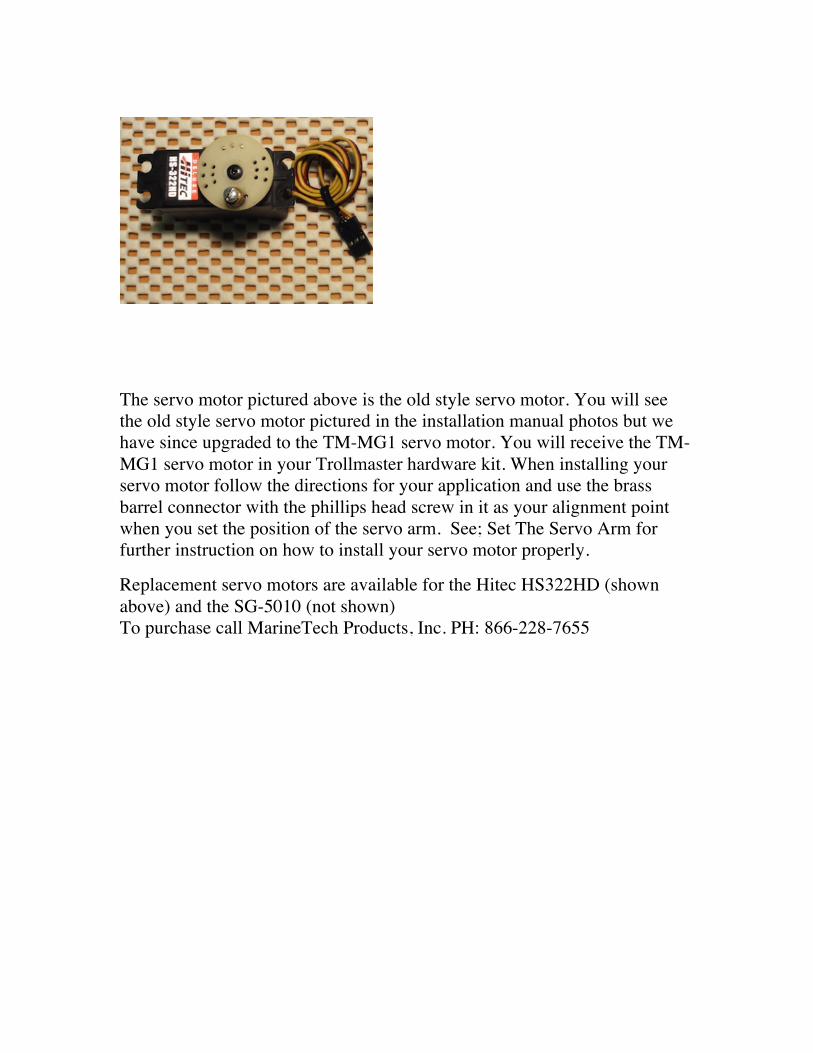
1. Attach the servo bracket to the top stud that mounts the carburetor to the intake manifold.
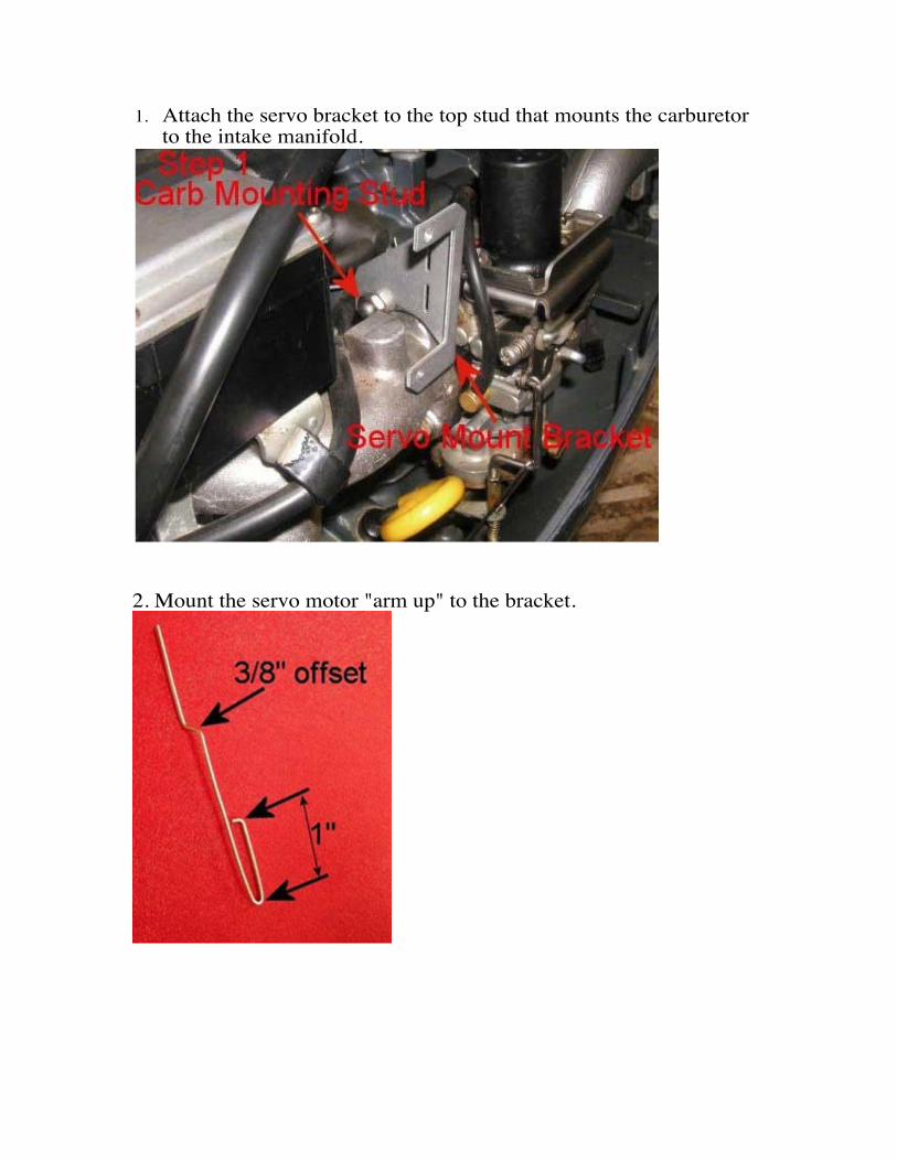
2. Mount the servo motor "arm up" to the bracket.
3. Install the connecting rod as shown below.
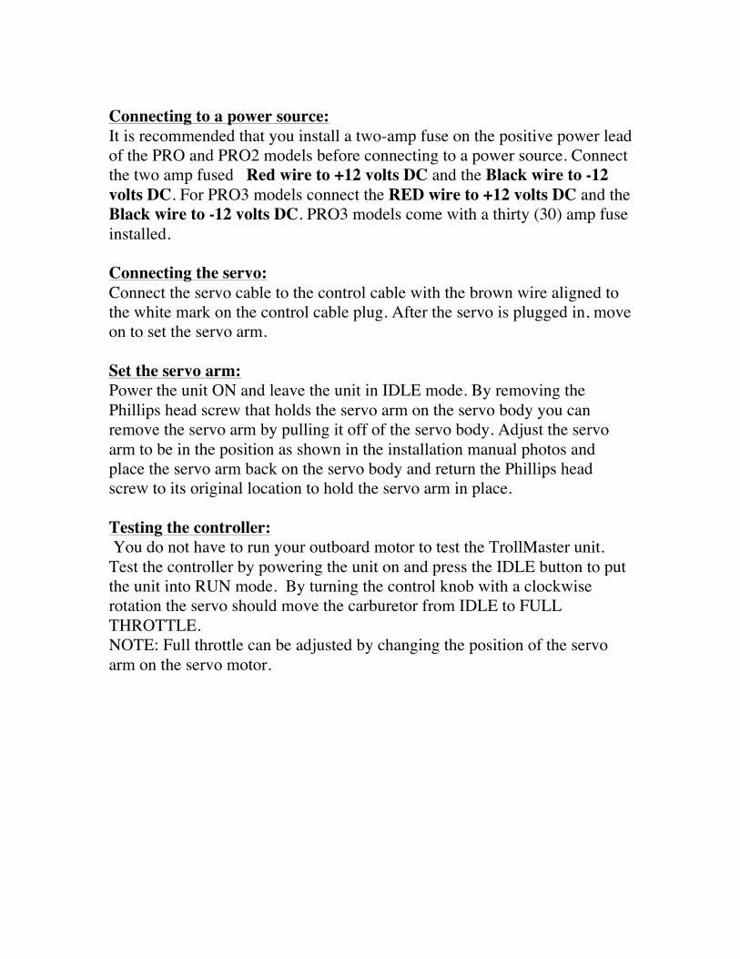
Connecting to a power source: It is recommended that you install a two-amp fuse on the positive power lead of the PRO and PRO2 models before connecting to a power source. Connect the two amp fused Red wire to +12 volts DC and the Black wire to -12 volts DC. For PRO3 models connect the RED wire to +12 volts DC and the Black wire to -12 volts DC. PRO3 models come with a thirty (30) amp fuse installed. Connecting the servo: Connect the servo cable to the control cable with the brown wire aligned to the white mark on the control cable plug. After the servo is plugged in, move on to set the servo arm. Set the servo arm: Power the unit ON and leave the unit in IDLE mode. By removing the Phillips head screw that holds the servo arm on the servo body you can remove the servo arm by pulling it off of the servo body. Adjust the servo arm to be in the position as shown in the installation manual photos and place the servo arm back on the servo body and return the Phillips head screw to its original location to hold the servo arm in place. Testing the controller: You do not have to run your outboard motor to test the TrollMaster unit. Test the controller by powering the unit on and press the IDLE button to put the unit into RUN mode. By turning the control knob with a clockwise rotation the servo should move the carburetor from IDLE to FULL THROTTLE. NOTE: Full throttle can be adjusted by changing the position of the servo arm on the servo motor.

Troubleshooting:
If you should encounter an issue with your TrollMaster use these tips to determine the best course of action to resolve the issue. Problem: The unit powers on and the display functions properly, your buttons show function on the screen and the numbers increase when turning the speed adjustment knob but there is no response from the servo motor. Solution: Verify the servo motor is plugged in accordingly with the brown wire aligned with the white mark on the control cable plug and test again. If there is still no response, replace the servo motor with a new one and test again. If after replacing the servo motor and testing again there is still no response contact MarineTech Products Inc. 866-228-7655 to have the unit inspected at our facility. Problem: The unit powers on works momentarily then powers off. The unit will not stay powered on. Solution: Check your battery voltage; if the battery voltage is low the unit will not operate properly. When in doubt charge your battery to ensure there is enough voltage to operate the TrollMaster unit to its fullest potential. If the battery is fully charged and the unit is still not operating properly contact MarineTech Products, Inc. 866-228-7655 to have the unit inspected at our facility. If you need assistance with Troubleshooting contact MarineTech Products, Inc. For tech support. Call 866-228-7655
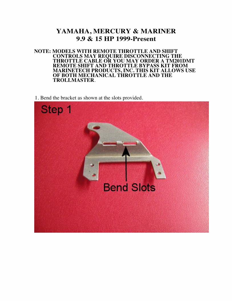
YAMAHA, MERCURY & MARINER 9.9 & 15 HP 1999-Present
NOTE: MODELS WITH REMOTE THROTTLE AND SHIFT
CONTROLS MAY REQUIRE DISCONNECTING THE THROTTLE CABLE OR YOU MAY ORDER A TM201DMT REMOTE SHIFT AND THROTTLE BYPASS KIT FROM MARINETECH PRODUCTS, INC. THIS KIT ALLOWS USE OF BOTH MECHANICAL THROTTLE AND THE TROLLMASTER.
1. Bend the bracket as shown at the slots provided.
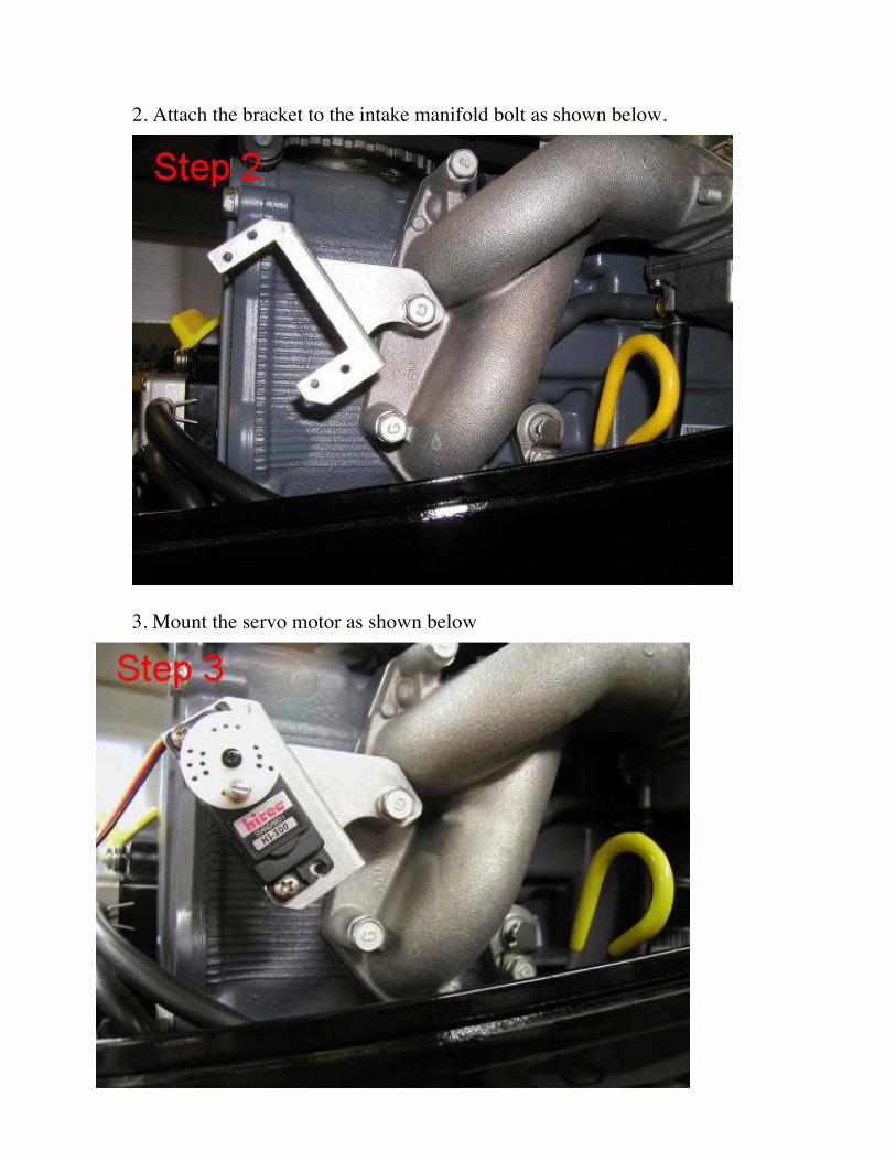
2. Attach the bracket to the intake manifold bolt as shown below.
3. Mount the servo motor as shown below
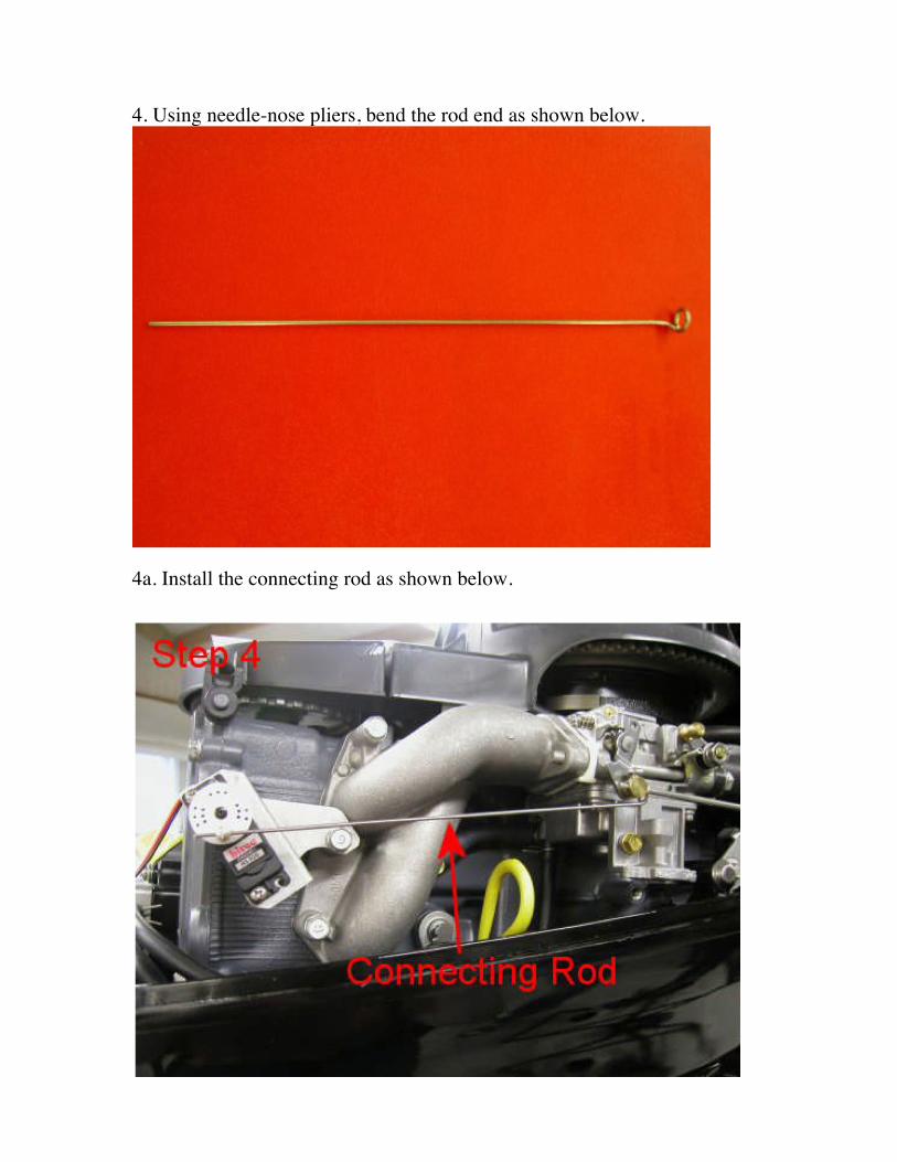
4. Using needle-nose pliers, bend the rod end as shown below.
4a. Install the connecting rod as shown below.
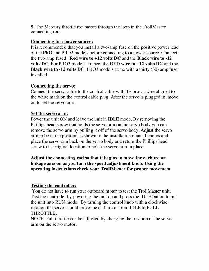
5. The Mercury throttle rod passes through the loop in the TrollMaster connecting rod. Connecting to a power source: It is recommended that you install a two-amp fuse on the positive power lead of the PRO and PRO2 models before connecting to a power source. Connect the two amp fused Red wire to +12 volts DC and the Black wire to -12 volts DC. For PRO3 models connect the RED wire to +12 volts DC and the Black wire to -12 volts DC. PRO3 models come with a thirty (30) amp fuse installed. Connecting the servo: Connect the servo cable to the control cable with the brown wire aligned to the white mark on the control cable plug. After the servo is plugged in, move on to set the servo arm. Set the servo arm: Power the unit ON and leave the unit in IDLE mode. By removing the Phillips head screw that holds the servo arm on the servo body you can remove the servo arm by pulling it off of the servo body. Adjust the servo arm to be in the position as shown in the installation manual photos and place the servo arm back on the servo body and return the Phillips head screw to its original location to hold the servo arm in place. Adjust the connecting rod so that it begins to move the carburetor linkage as soon as you turn the speed adjustment knob. Using the operating instructions check your TrollMaster for proper movement Testing the controller: You do not have to run your outboard motor to test the TrollMaster unit. Test the controller by powering the unit on and press the IDLE button to put the unit into RUN mode. By turning the control knob with a clockwise rotation the servo should move the carburetor from IDLE to FULL THROTTLE. NOTE: Full throttle can be adjusted by changing the position of the servo arm on the servo motor.
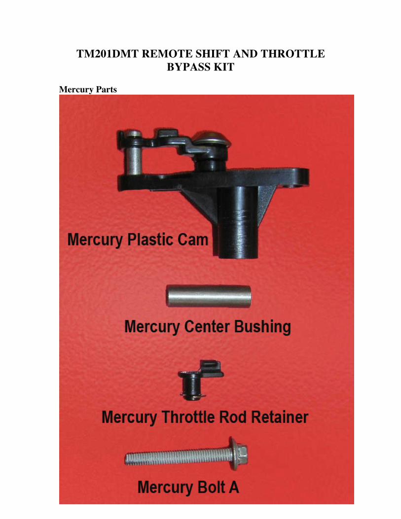
TM201DMT REMOTE SHIFT AND THROTTLE BYPASS KIT
Mercury Parts
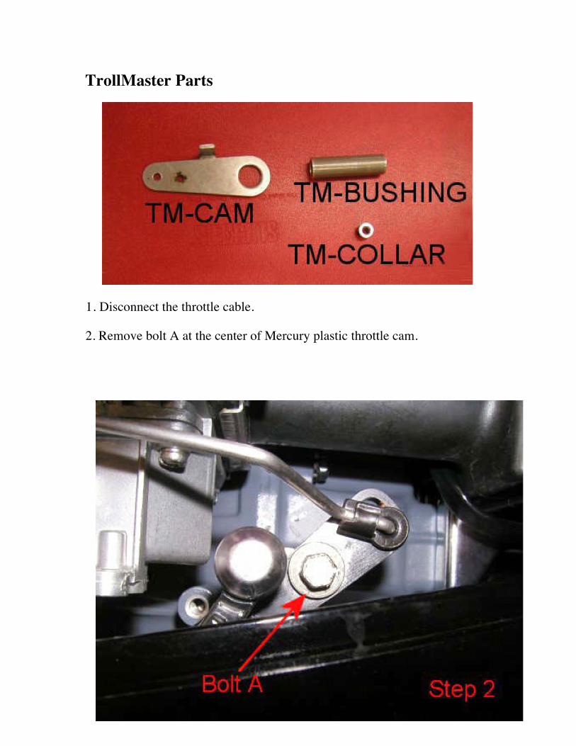
TrollMaster Parts
1. Disconnect the throttle cable. 2. Remove bolt A at the center of Mercury plastic throttle cam.
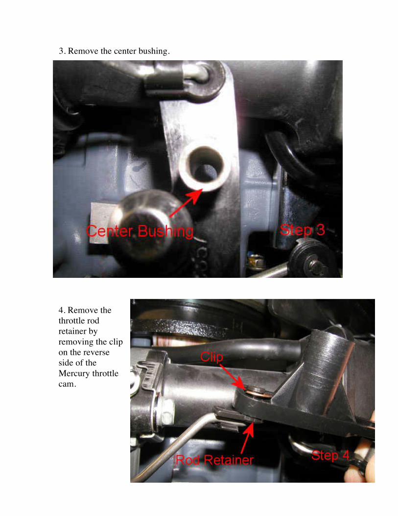
3. Remove the center bushing.
4. Remove the throttle rod retainer by removing the clip on the reverse side of the Mercury throttle cam.
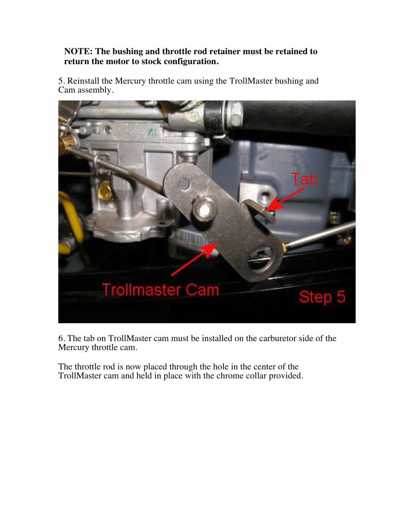
NOTE: The bushing and throttle rod retainer must be retained to return the motor to stock configuration.
5. Reinstall the Mercury throttle cam using the TrollMaster bushing and Cam assembly.
6. The tab on TrollMaster cam must be installed on the carburetor side of the Mercury throttle cam. The throttle rod is now placed through the hole in the center of the TrollMaster cam and held in place with the chrome collar provided.
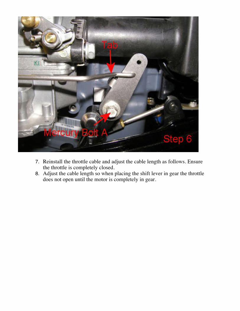
7. Reinstall the throttle cable and adjust the cable length as follows. Ensure
the throttle is completely closed. 8. Adjust the cable length so when placing the shift lever in gear the throttle
does not open until the motor is completely in gear.
Connecting to a power source: It is recommended that you install a two-amp fuse on the positive power lead of the PRO and PRO2 models before connecting to a power source. Connect the two amp fused Red wire to +12 volts DC and the Black wire to -12 volts DC. For PRO3 models connect the RED wire to +12 volts DC and the Black wire to -12 volts DC. PRO3 models come with a thirty (30) amp fuse installed. Connecting the servo: Connect the servo cable to the control cable with the brown wire aligned to the white mark on the control cable plug. After the servo is plugged in, move on to set the servo arm. Set the servo arm: Power the unit ON and leave the unit in IDLE mode. By removing the Phillips head screw that holds the servo arm on the servo body you can remove the servo arm by pulling it off of the servo body. Adjust the servo arm to be in the position as shown in the installation manual photos and place the servo arm back on the servo body and return the Phillips head screw to its original location to hold the servo arm in place. Testing the controller: You do not have to run your outboard motor to test the TrollMaster unit. Test the controller by powering the unit on and press the IDLE button to put the unit into RUN mode. By turning the control knob with a clockwise rotation the servo should move the carburetor from IDLE to FULL THROTTLE. NOTE: Full throttle can be adjusted by changing the position of the servo arm on the servo motor.

Troubleshooting:
If you should encounter an issue with your TrollMaster use these tips to determine the best course of action to resolve the issue. Problem: The unit powers on and the display functions properly, your buttons show function on the screen and the numbers increase when turning the speed adjustment knob but there is no response from the servo motor. Solution: Verify the servo motor is plugged in accordingly with the brown wire aligned with the white mark on the control cable plug and test again. If there is still no response, replace the servo motor with a new one and test again. If after replacing the servo motor and testing again there is still no response contact MarineTech Products Inc. 866-228-7655 to have the unit inspected at our facility. Problem: The unit powers on works momentarily then powers off. The unit will not stay powered on. Solution: Check your battery voltage; if the battery voltage is low the unit will not operate properly. When in doubt charge your battery to ensure there is enough voltage to operate the TrollMaster unit to its fullest potential. If the battery is fully charged and the unit is still not operating properly contact MarineTech Products, Inc. 866-228-7655 to have the unit inspected at our facility. If you need assistance with Troubleshooting contact MarineTech Products, Inc. For tech support. Call 866-228-7655
TrollMaster Replacement Parts:
TrollMaster Servo Motor (TM-MG1) Note: A Servo Arm is included with the purchase of a replacement Servo Motor.
TrollMaster Servo Arm (TM-Servo Arm) Note: A replacement screw to mount the Servo Arm to the Servo Body is included with the purchase of a replacement Servo Arm.
TrollMaster Hardware Kit (TMXXXHRDWRKIT) Note: Replace the XXX with the Kit number that applies to your outboard motor. See the Application Guide for kit number. Example: TM206HRDWRKIT.
TrollMaster Electronics Unit Only (TMXXXXUNITONLY) Note: Replace the XXXX with the model of Replacement TrollMaster Electronics you wish to purchase. Comes with controller and wiring only, does not include servo motor or hardware kit. Examples: TMPROUNITONLY, TMPRO2UNITONLY, TMPRO3UNITONLY.
To Order Replacement Parts: If you would like to order any of the above mentioned replacement parts check with your local retailer, if they do not have the item in stock they can order it for you or you can order directly from MarineTech Products, Inc. For pricing and availability call MarineTech Products, Inc. 866-228-7655
Installation Guides: The installation Guide on this disk can also be found online at MarineTech Products website, visit: www.marinetechproducts.com and follow the TrollMaster link to the TrollMaster page where you will find the Installation Guides for every motor we make a kit to fit. The Application Guide is also on the same web page; the Application Guide shows the full list of motors we make kits to fit with the product part numbers for those kits
SERVICE AND WARRANTY
Should your unit ever require service please do not return the product to your dealer. Instead call the number below for special instructions on shipping and handling. Be sure to call between 9 00 AM and 4.00 PM (Central Time) Monday through Friday. If the service required is covered by the warranty, it will be repaired or replaced as described below. If the service required is NOT covered by warranty replacement parts are available for purchase and paid for by a major credit card.
The warranty coverage on this equipment is limited to the terms set forth below:
MarineTech Products, Inc. warrants this product to be free of defects in material and workmanship for a period of ONE (1) YEAR from the date of original retail purchase. Positive proof of date of purchase is required for warranty service. If the service required is covered by warranty, you must obtain a Return Authorization number from MarineTech Products. The unit will be repaired or replaced with new or factory rebuilt parts at no charge. The defective components must he returned to the address specified, with shipping charges prepaid. Be sure to include your name, address, telephone number and a copy of the sales receipt showing the date of original retail purchase. All sales receipts are subject to verification.
This warranty does not apply if the unit has been damaged by accident, abuse, misuse, poor installation or misapplication, or if It has been modified from its original condition, or if any serial number has been removed or defaced or altered. This warranty does not cover any expense to remove or reinstall the unit or any of its components. If a returned unit is not covered by warranty, the sender will he notified and given an estimate of the charges to repair or replace the unit together with the return shipping charges.
THIS WARRANTY DOES NOT COVER SPECIAL, INCIDENTAL, OR CONSEQUENTIAL DAMAGES RESULTING FROM ANY BREACH OF WARRANTY, OR UNDER ANY OTHER LEGAL THEORY, INCLUDING BUT NOT LIMITED TO DAMAGE TO OR REPLACEMENT OF OTHER EQUIPMENT AND PROPERTY. THE WARRANTY AND REMEDIES SET FORTH ARE EXCLUSIVE AND IN LIEU OF ALL OTHERS, WHETHER ORAL OR WRITTEN, EXPRESS OR IMPLIED. DUE TO THE SPECIAL AND UNIQUE CONDITIONS THAT MAY EXIST IN EACH APPLICATION, THE MANUFACTURER SPECIFICALLY DISCLAIMS ANY AND ALL IMPLIED WARRANTIES OF MERCHANTABILITY AND FITNESS FOR A PARTICULAR PURPOSE. NO DEALER, AGENT OR EMPLOYEE IS AUTHORIZED TO MAKE ANY MODIFICATION, EXTENSION OR ADDITION TO THIS WARRANTY.
Some states do not allow exclusion of incidental or consequential damages, so the above exclusions may not apply to you. This warranty gives you specific legal rights, and you may also have other legal rights, which may vary from state to state.
FOR SERVICE CALL: 1 651 486 2010