Embed Size (px)
Citation preview
Copyright 2012
HVAC Systems at Y2E2
CEE 243
Y2E2 – HVAC sequence of operation
(controls)
Week 3

Copyright 2012
HVAC Systems at Y2E2
CEE 243
Big idea
• Modern energy management systems include a
combination of passive and active control of energy
distribution
– Passive: constant (volume/flow)
– Active: variable (volume/flow) under computer
control
• Based on If-then conditional control rules of
general form
If setpoint value out of range and
Other conditions met
Then adjust control variable value
2
Copyright 2012
HVAC Systems at Y2E2
CEE 243
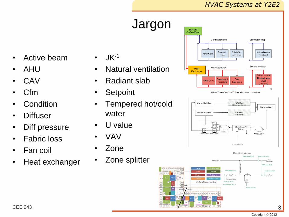
Jargon
• Active beam
• AHU
• CAV
• Cfm
• Condition
• Diffuser
• Diff pressure
• Fabric loss
• Fan coil
• Heat exchanger
• JK-1
• Natural ventilation
• Radiant slab
• Setpoint
• Tempered hot/cold
water
• U value
• VAV
• Zone
• Zone splitter
3
Copyright 2012
HVAC Systems at Y2E2
CEE 243
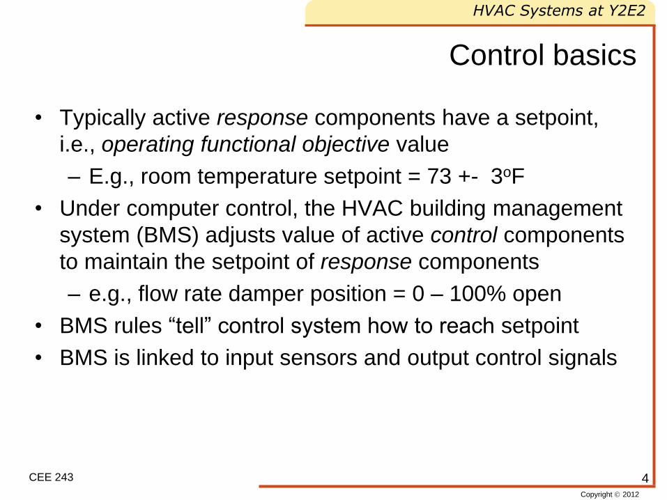
Control basics
• Typically active response components have a setpoint,
i.e., operating functional objective value
– E.g., room temperature setpoint = 73 +- 3oF
• Under computer control, the HVAC building management
system (BMS) adjusts value of active control components
to maintain the setpoint of response components
– e.g., flow rate damper position = 0 – 100% open
• BMS rules “tell” control system how to reach setpoint
• BMS is linked to input sensors and output control signals
4
Copyright 2012
HVAC Systems at Y2E2
CEE 243
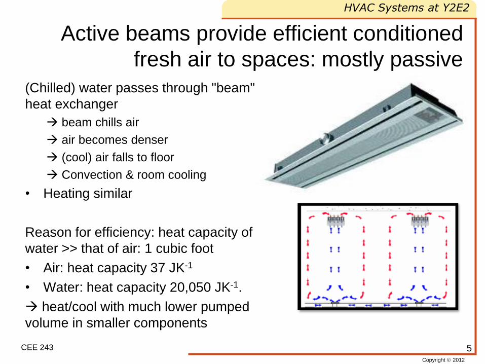
Active beams provide efficient conditioned
fresh air to spaces: mostly passive
5
(Chilled) water passes through "beam"
heat exchanger
beam chills air
air becomes denser
(cool) air falls to floor
Convection & room cooling
• Heating similar
Reason for efficiency: heat capacity of
water >> that of air: 1 cubic foot
• Air: heat capacity 37 JK-1
• Water: heat capacity 20,050 JK-1.
heat/cool with much lower pumped
volume in smaller components
Copyright 2012
HVAC Systems at Y2E2
CEE 243
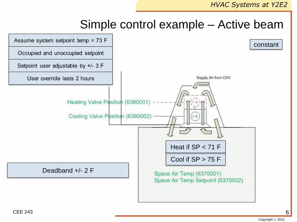
Simple control example – Active beam
6
constant
Cool if SP > 75 F
Heat if SP < 71 F
Deadband +/- 2 F
Copyright 2012
HVAC Systems at Y2E2
CEE 243
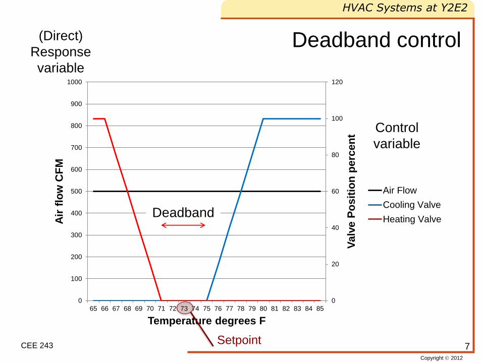
Deadband control
7
0
20
40
60
80
100
120
0
100
200
300
400
500
600
700
800
900
1000
65 66 67 68 69 70 71 72 73 74 75 76 77 78 79 80 81 82 83 84 85
Valv
e P
osit
ion
perc
en
t
Air
flo
w C
FM
Temperature degrees F
Air Flow
Cooling Valve
Heating Valve
Setpoint
Control
variable
(Direct)
Response
variable
Deadband
Copyright 2012
HVAC Systems at Y2E2
CEE 243
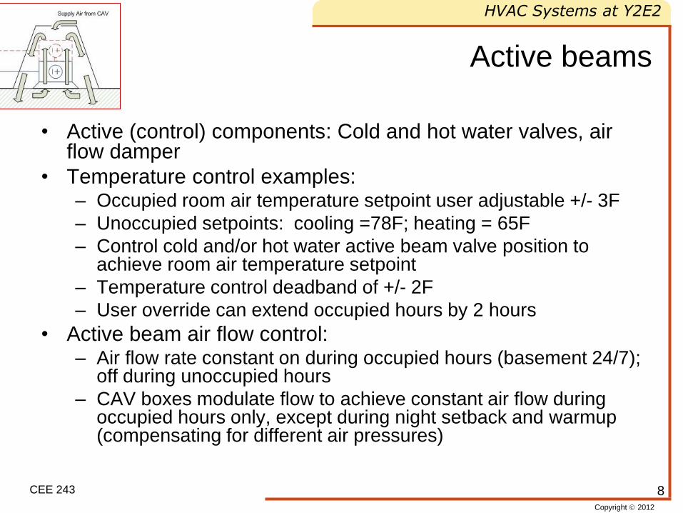
Active beams
• Active (control) components: Cold and hot water valves, air flow damper
• Temperature control examples: – Occupied room air temperature setpoint user adjustable +/- 3F
– Unoccupied setpoints: cooling =78F; heating = 65F
– Control cold and/or hot water active beam valve position to achieve room air temperature setpoint
– Temperature control deadband of +/- 2F
– User override can extend occupied hours by 2 hours
• Active beam air flow control: – Air flow rate constant on during occupied hours (basement 24/7);
off during unoccupied hours
– CAV boxes modulate flow to achieve constant air flow during occupied hours only, except during night setback and warmup (compensating for different air pressures)
8
Copyright 2012
HVAC Systems at Y2E2
CEE 243
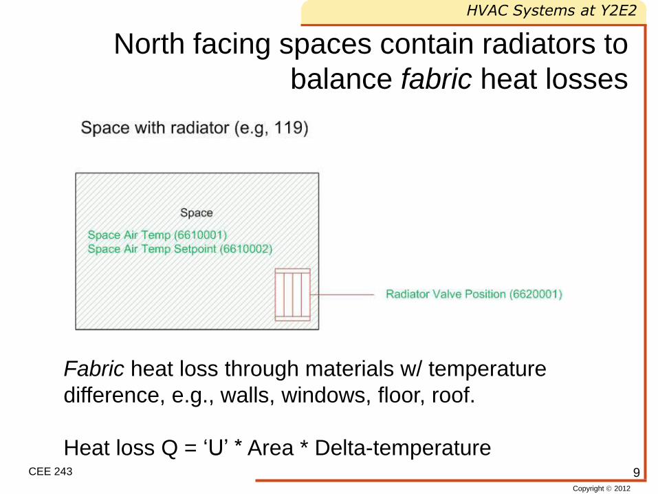
North facing spaces contain radiators to
balance fabric heat losses
9
Fabric heat loss through materials w/ temperature
difference, e.g., walls, windows, floor, roof.
Heat loss Q = ‘U’ * Area * Delta-temperature
Copyright 2012
HVAC Systems at Y2E2
CEE 243
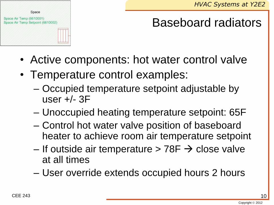
Baseboard radiators
• Active components: hot water control valve
• Temperature control examples:
– Occupied temperature setpoint adjustable by user +/- 3F
– Unoccupied heating temperature setpoint: 65F
– Control hot water valve position of baseboard heater to achieve room air temperature setpoint
– If outside air temperature > 78F close valve at all times
– User override extends occupied hours 2 hours
10
Copyright 2012
HVAC Systems at Y2E2
CEE 243
Conference rooms
• Active beam control as in other rooms
• Active component: inline supply fan
• Additional CO2 level control
– If CO2 concentration > max CO2 setpoint
open inline supply fan
– Max CO2 setpoint = 500 ppm above outside
air CO2 concentration
11
Copyright 2012
HVAC Systems at Y2E2
CEE 243
Laboratories
• Active components: damper, water coil valves
• Air flow control
– The greater of: • The required air changes (6 air changes/hr)
• Amount needed for cooling
• Sufficient makeup air for fume hoods (supply ~ exhaust)
– For heating air flow is set to minimum
– For cooling air flow is set to maximum
• Temperature control
– +/- 2F deadband
12
Copyright 2012
HVAC Systems at Y2E2
CEE 243
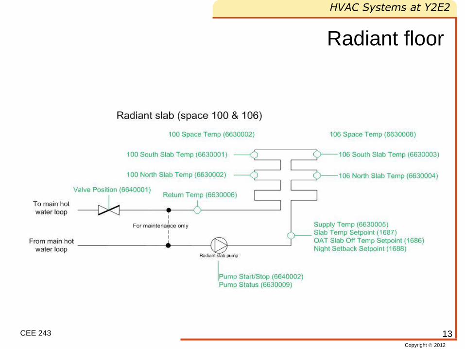
Radiant floor
13
Copyright 2012
HVAC Systems at Y2E2
CEE 243
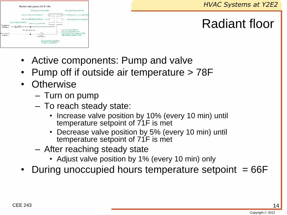
Radiant floor
• Active components: Pump and valve
• Pump off if outside air temperature > 78F
• Otherwise – Turn on pump
– To reach steady state: • Increase valve position by 10% (every 10 min) until
temperature setpoint of 71F is met
• Decrease valve position by 5% (every 10 min) until temperature setpoint of 71F is met
– After reaching steady state • Adjust valve position by 1% (every 10 min) only
• During unoccupied hours temperature setpoint = 66F
14
Copyright 2012
HVAC Systems at Y2E2
CEE 243
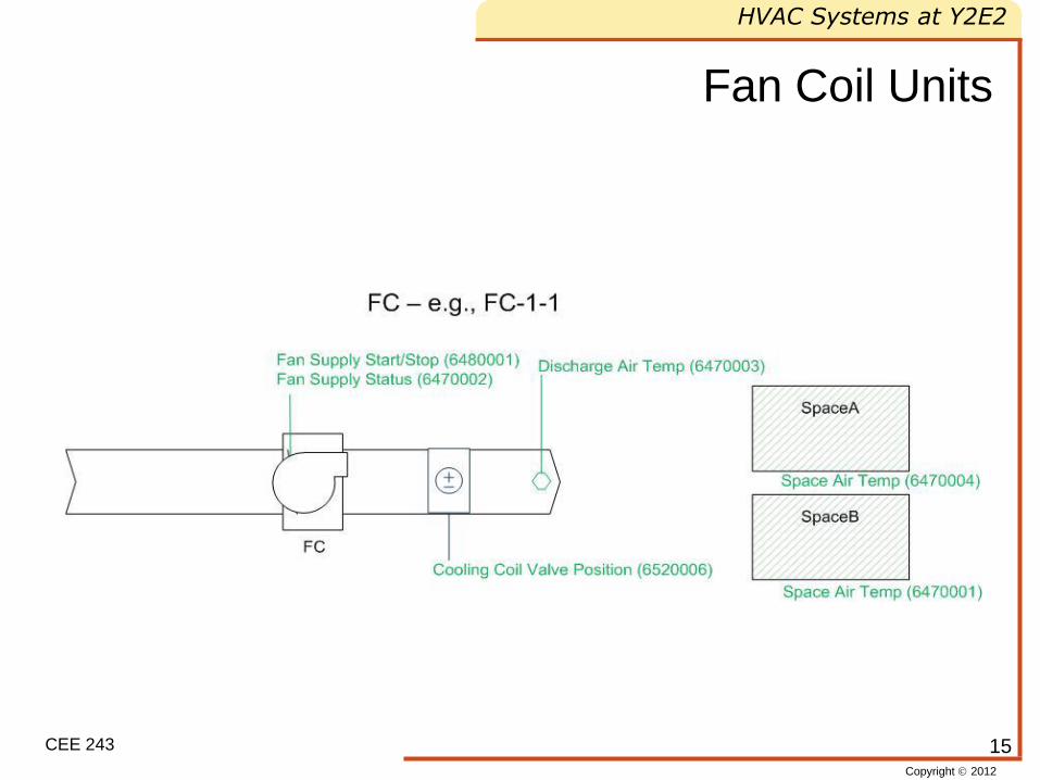
Fan Coil Units
15
Copyright 2012
HVAC Systems at Y2E2
CEE 243
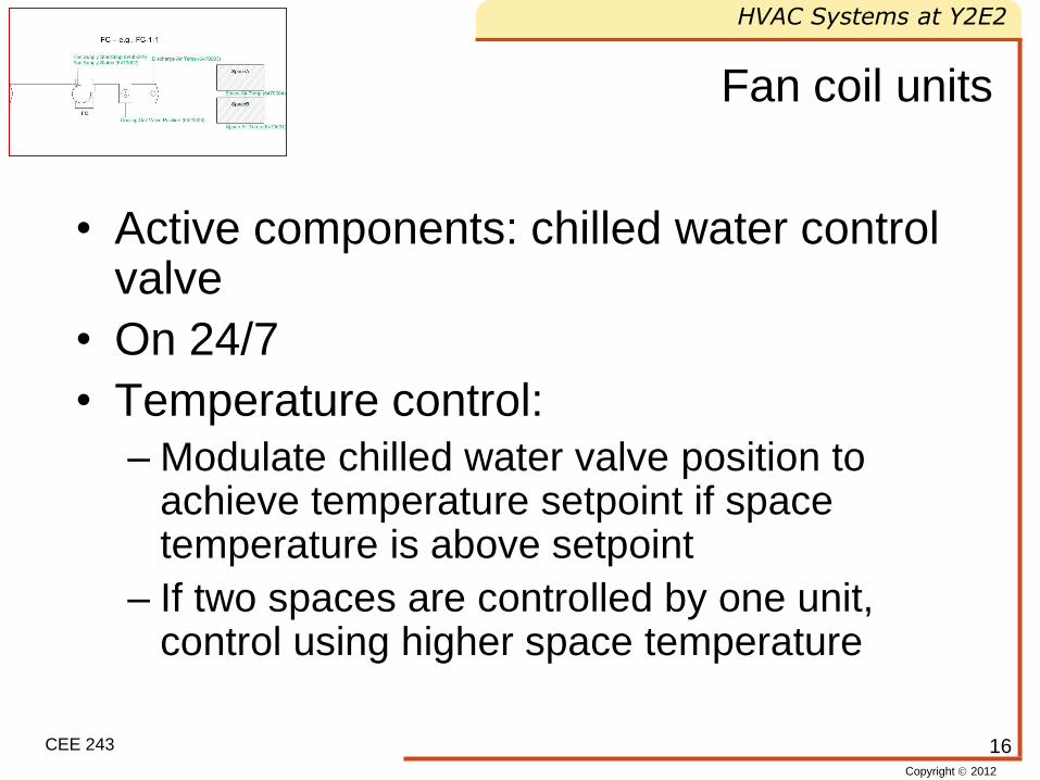
Fan coil units
• Active components: chilled water control valve
• On 24/7
• Temperature control:
– Modulate chilled water valve position to achieve temperature setpoint if space temperature is above setpoint
– If two spaces are controlled by one unit, control using higher space temperature
16
Copyright 2012
HVAC Systems at Y2E2
CEE 243
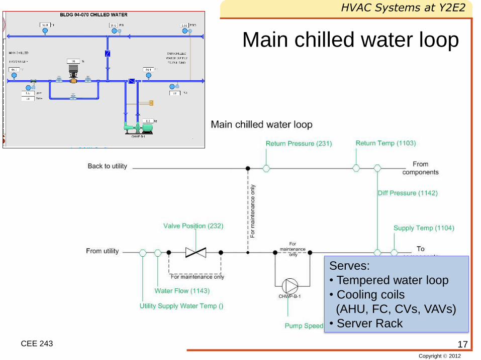
Main chilled water loop
17
Serves:
• Tempered water loop
• Cooling coils
(AHU, FC, CVs, VAVs)
• Server Rack
Copyright 2012
HVAC Systems at Y2E2
CEE 243
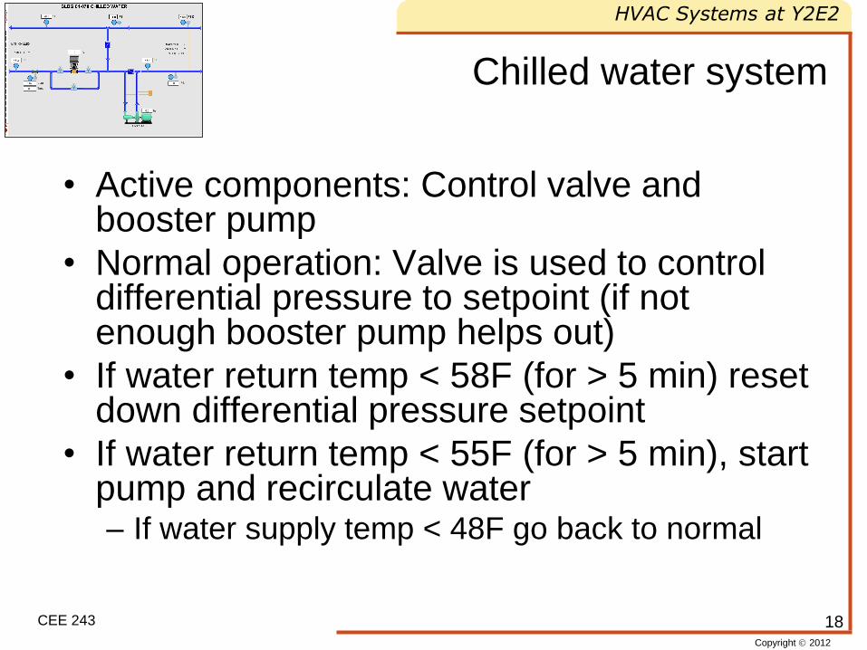
Chilled water system
• Active components: Control valve and booster pump
• Normal operation: Valve is used to control differential pressure to setpoint (if not enough booster pump helps out)
• If water return temp < 58F (for > 5 min) reset down differential pressure setpoint
• If water return temp < 55F (for > 5 min), start pump and recirculate water – If water supply temp < 48F go back to normal
18
Copyright 2012
HVAC Systems at Y2E2
CEE 243
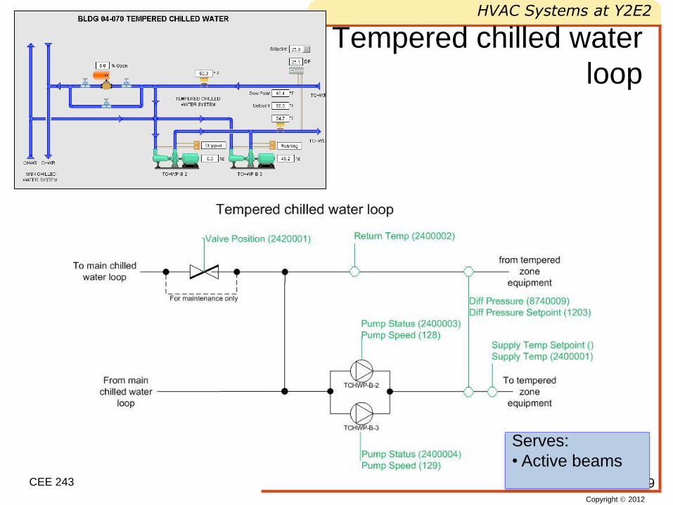
Tempered chilled water
loop
19
Serves:
• Active beams
Copyright 2012
HVAC Systems at Y2E2
CEE 243
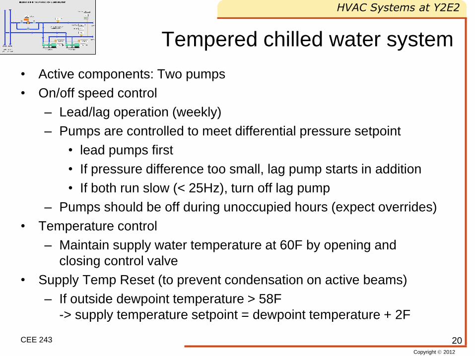
Tempered chilled water system
• Active components: Two pumps
• On/off speed control
– Lead/lag operation (weekly)
– Pumps are controlled to meet differential pressure setpoint
• lead pumps first
• If pressure difference too small, lag pump starts in addition
• If both run slow (< 25Hz), turn off lag pump
– Pumps should be off during unoccupied hours (expect overrides)
• Temperature control
– Maintain supply water temperature at 60F by opening and
closing control valve
• Supply Temp Reset (to prevent condensation on active beams)
– If outside dewpoint temperature > 58F
-> supply temperature setpoint = dewpoint temperature + 2F
20
Copyright 2012
HVAC Systems at Y2E2
CEE 243
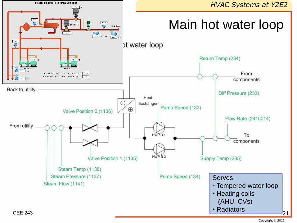
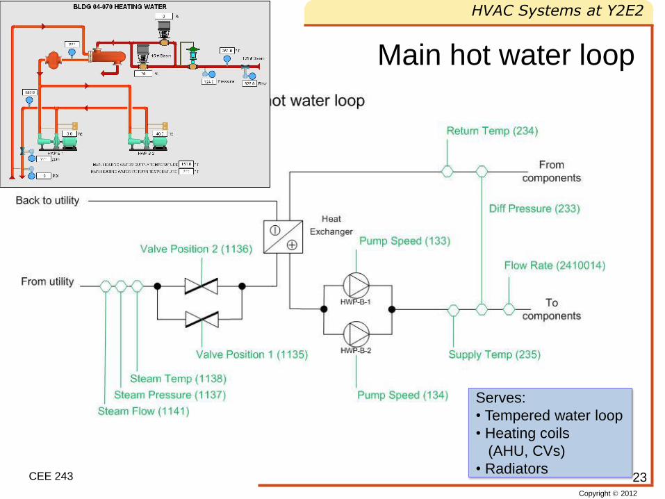
Main hot water loop
21
Serves:
• Tempered water loop
• Heating coils
(AHU, CVs)
• Radiators
Copyright 2012
HVAC Systems at Y2E2
CEE 243
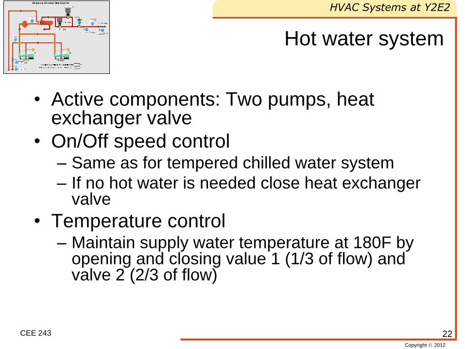
Hot water system
• Active components: Two pumps, heat exchanger valve
• On/Off speed control – Same as for tempered chilled water system
– If no hot water is needed close heat exchanger valve
• Temperature control – Maintain supply water temperature at 180F by
opening and closing value 1 (1/3 of flow) and valve 2 (2/3 of flow)
22
Copyright 2012
HVAC Systems at Y2E2
CEE 243
Main hot water loop
23
Serves:
• Tempered water loop
• Heating coils
(AHU, CVs)
• Radiators
Copyright 2012
HVAC Systems at Y2E2
CEE 243
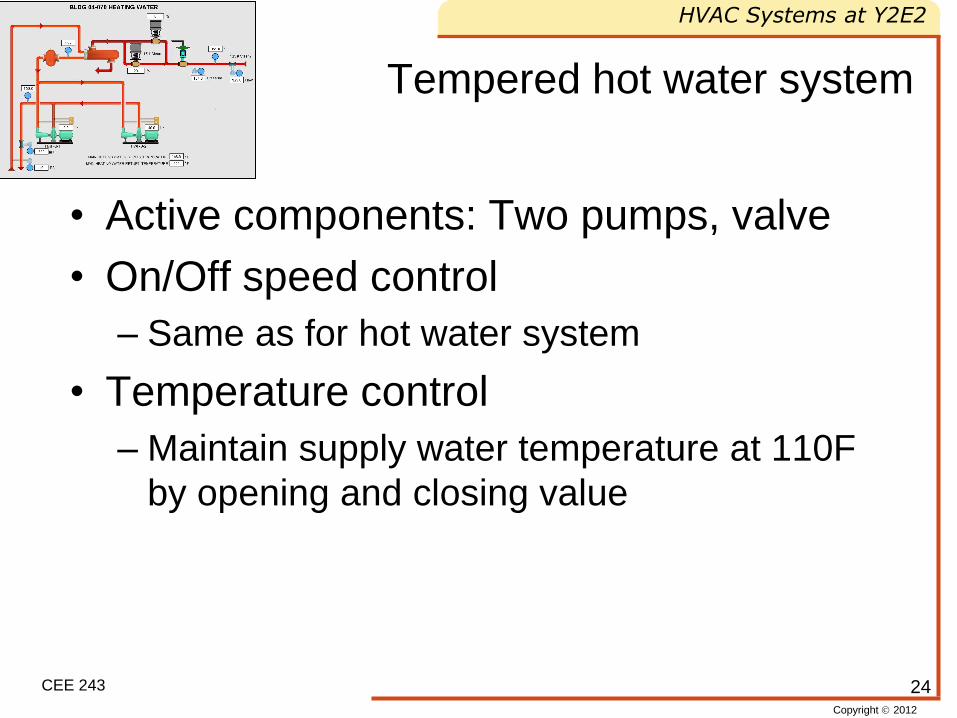
Tempered hot water system
• Active components: Two pumps, valve
• On/Off speed control
– Same as for hot water system
• Temperature control
– Maintain supply water temperature at 110F
by opening and closing value
24
Copyright 2012
HVAC Systems at Y2E2
CEE 243
Air handling unit
25
Copyright 2012
HVAC Systems at Y2E2
CEE 243
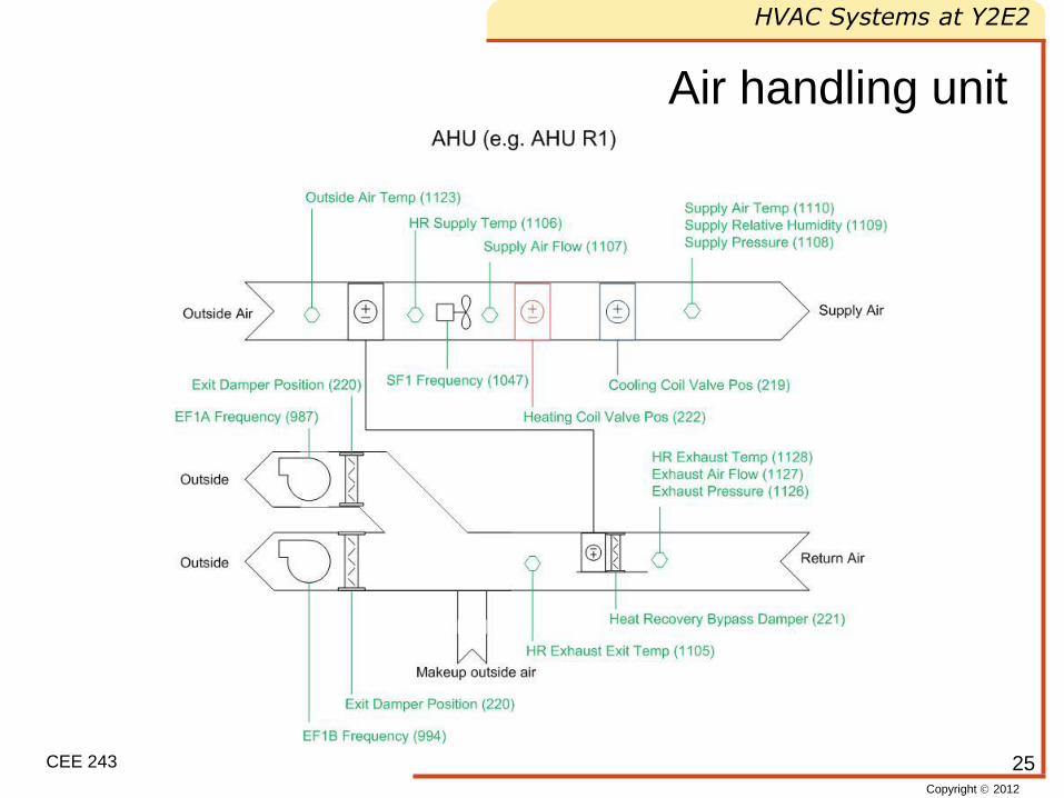
Air handling unit
26
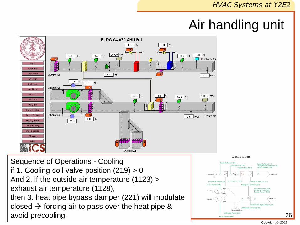
Sequence of Operations - Cooling
if 1. Cooling coil valve position (219) > 0
And 2. if the outside air temperature (1123) >
exhaust air temperature (1128),
then 3. heat pipe bypass damper (221) will modulate
closed forcing air to pass over the heat pipe &
avoid precooling.
Copyright 2012
HVAC Systems at Y2E2
CEE 243
Air Handling Units (1)
• Active components: fans, heating and cooling coil water valve, heat recovery bypass valve, cooling coil bypass valve
• 24/7 because of labs in the basement
• Maintain static pressure setpoint by modulating fan speed
• Supply air to be maintained at 65F (max DewPoint 60F)
• Cooling, Heating, Dehumidification, Morning Warm-up
27
Copyright 2012
HVAC Systems at Y2E2
CEE 243
Air Handling Units (2) - cooling
• Active components: heat recovery bypass damper, cooling coil
bypass damper, cooling coil valve
• Heat recovery
– If outside air temperature > exhaust air temperture -> heat
recovery bypass damper closed (heat recovery “on”) otherwise
open
– Heat recovery bypass damper modulates to set supply air
temperature to setpoint
• Cooling
– If no heating and supply air temperature > setpoint
-> cooling coil bypass damper closed and cooling coil valve
modulates to achieve setpoint
– If no heating and supply air temperature < setpoint
-> first close valve then close bypass damper 28
Copyright 2012
HVAC Systems at Y2E2
CEE 243
Air Handling Units (3) - heating
• Active components: heat recovery bypass damper, cooling coil
bypass damper, cooling coil valve
• Heat recovery
– If outside air temperature < heat recovery leaving temperature
& exhaust air temperature > heat recovery leaving temperature
-> heat recovery bypass damper closed (heat recovery “on”)
otherwise open
– Heat recovery bypass damper modulates to set supply air
temperature to setpoint
• Heating
– If no cooling and supply air temperature < setpoint
-> heating coil bypass damper closed and heating coil valve
modulates to achieve setpoint
– If no cooling and supply air temperature > setpoint
-> first close valve then close bypass damper 29
Copyright 2012
HVAC Systems at Y2E2
CEE 243
Air Handling Units (4) - dehumidification
• If leaving air dewpoint temperature > 60 F
then maintain dewpoint setpoint in
addition to temperature setpoint with
additional heating to lower moisture
content in air
30
Copyright 2012
HVAC Systems at Y2E2
CEE 243
Air Handling Units (5) – Morning
warmup
• Only if daytime temperature does not
exceed 68F
– 2-6 am air supply temperature setpoint is set
to 69F
– After 6am everything is set to normal
31
Copyright 2012
HVAC Systems at Y2E2
CEE 243
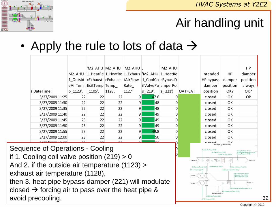
Air handling unit
• Apply the rule to lots of data
32
('DateTime',
M2_AHU
1_Outsid
eAirTem
p_1123',
'M2_AHU
1_HeatRe
cExhaust
ExitTemp
_1105',
M2_AHU
1_HeatRe
cExhaust
Temp_
1128',
'M2_AHU
1_Exhaus
tAirFlow
Rate_
1127'
,
'M2_AHU
1_CoolCo
ilValvePo
s_ 219',
'M2_AHU
1_HeatRe
cBypassD
amperPo
s_ 221') OAT>EAT
Intended
HP bypass
damper
position
HP
damper
position
OK?
HP
damper
position
always
OK?
3/27/2009 11:25 22 22 22 9 47.6 0 closed OK Ok
3/27/2009 11:30 22 22 22 9 48 0 closed OK
3/27/2009 11:35 22 22 22 9 48 0 closed OK
3/27/2009 11:40 22 22 22 9 49 0 closed OK
3/27/2009 11:45 23 22 22 9 49 0 closed OK
3/27/2009 11:50 23 22 22 9 49 0 closed OK
3/27/2009 11:55 23 22 22 9 49.8 0 closed OK
3/27/2009 12:00 23 22 22 9 50 0 closed OK
3/27/2009 12:05 23 22 22 9 50 0 closed OK
3/27/2009 12:10 23 22 22 9 51 0 closed OK
3/27/2009 12:15 23 22 22 9 51 0 closed OK
Cooling if 1. Cooling coil valve position (219) > 0And 2. if the outside air temperature (1123) > exhaust air temperature (1128),
then 3. heat pipe bypass damper (221) will modulate closed the heat pipe & avoid precooling.
Sequence of Operations - Cooling
if 1. Cooling coil valve position (219) > 0
And 2. if the outside air temperature (1123) >
exhaust air temperature (1128),
then 3. heat pipe bypass damper (221) will modulate
closed forcing air to pass over the heat pipe &
avoid precooling.
Copyright 2012
HVAC Systems at Y2E2
CEE 243
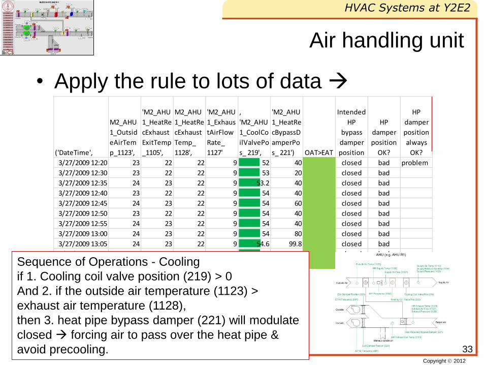
Air handling unit
• Apply the rule to lots of data
33
('DateTime',
M2_AHU
1_Outsid
eAirTem
p_1123',
'M2_AHU
1_HeatRe
cExhaust
ExitTemp
_1105',
M2_AHU
1_HeatRe
cExhaust
Temp_
1128',
'M2_AHU
1_Exhaus
tAirFlow
Rate_
1127'
,
'M2_AHU
1_CoolCo
ilValvePo
s_ 219',
'M2_AHU
1_HeatRe
cBypassD
amperPo
s_ 221') OAT>EAT
Intended
HP
bypass
damper
position
HP
damper
position
OK?
HP
damper
position
always
OK?
3/27/2009 12:20 23 22 22 9 52 40 closed bad problem
3/27/2009 12:30 23 22 22 9 53 20 closed bad
3/27/2009 12:35 24 23 22 9 53.2 40 closed bad
3/27/2009 12:40 23 22 22 9 54 40 closed bad
3/27/2009 12:45 24 23 22 9 54 60 closed bad
3/27/2009 12:50 23 22 22 9 54 40 closed bad
3/27/2009 12:55 24 23 22 9 54 40 closed bad
3/27/2009 13:00 24 23 22 9 54 80 closed bad
3/27/2009 13:05 24 23 22 9 54.6 99.8 closed bad
3/27/2009 13:10 24 23 22 9 54 100 closed bad
3/27/2009 13:15 24 23 22 9 54 49.75 closed bad
Cooling if 1. Cooling coil valve position (219) > 0And 2. if the outside air temperature (1123) > exhaust air temperature (1128),
then 3. heat pipe bypass damper (221) will modulate closed the heat pipe & avoid precooling.
Sequence of Operations - Cooling
if 1. Cooling coil valve position (219) > 0
And 2. if the outside air temperature (1123) >
exhaust air temperature (1128),
then 3. heat pipe bypass damper (221) will modulate
closed forcing air to pass over the heat pipe &
avoid precooling.
Copyright 2012
HVAC Systems at Y2E2
CEE 243
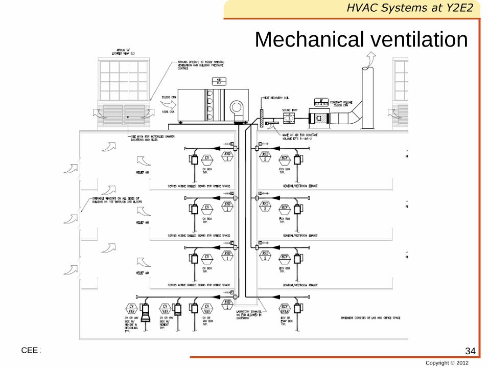
Mechanical ventilation
34
Copyright 2012
HVAC Systems at Y2E2
CEE 243
Building pressurization control
• Basement:
– Labs: Negative pressure: 5-10% more
exhaust air than supply
– Offices: Positive pressure: 5-10% more
supply air than exhaust
• Above Grade levels:
– If static pressure rises above 0.03” w.c. atria
dampers open to keep pressure below 0.03”
35
Copyright 2012
HVAC Systems at Y2E2
CEE 243
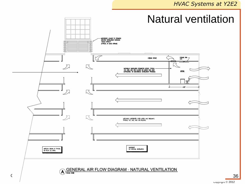
Natural ventilation
36
Copyright 2012
HVAC Systems at Y2E2
CEE 243
Natural ventilation
• Active components: Operable windows, atria damper
• Initial range for natural ventilation outside air temperature 68 – 85F
• If outdoor temperature is within range & average space
temperature > 70F -> open dampers
– For each zone where temperature > 70F open operable
windows
– If zone temperature < 70F for at least 5 min close windows
– If all windows around one atrium are closed close
corresponding atrium damper
• Night purge (if daytime outside air temperature exceeds 75F)
– During unoccupied hours open windows if Outside air
temperature < 65F and space temperature > 65F Close
windows if space temperature < 63F
37
Copyright 2012
HVAC Systems at Y2E2
CEE 243
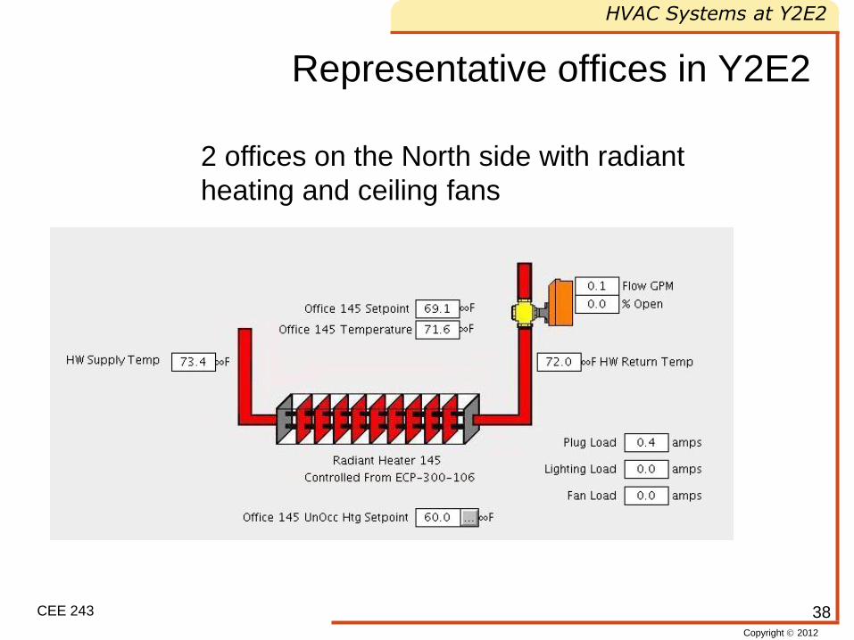
Representative offices in Y2E2
2 offices on the North side with radiant
heating and ceiling fans
38
Copyright 2012
HVAC Systems at Y2E2
CEE 243
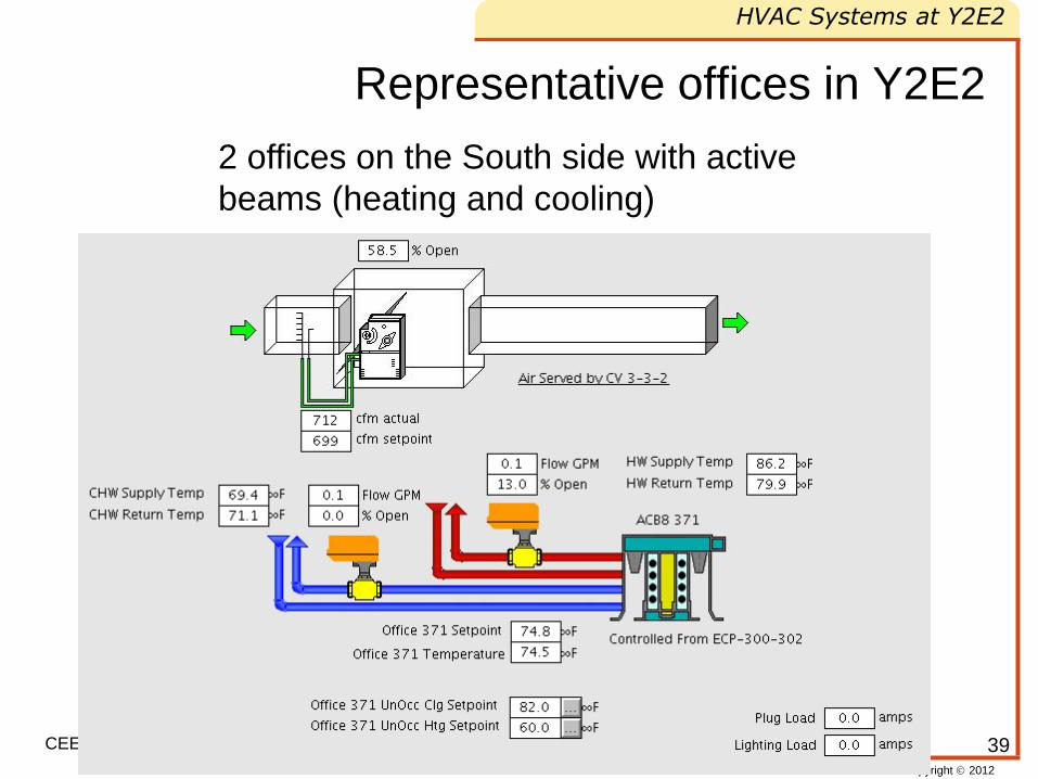
Representative offices in Y2E2
2 offices on the South side with active
beams (heating and cooling)
39
Copyright 2012
HVAC Systems at Y2E2
CEE 243
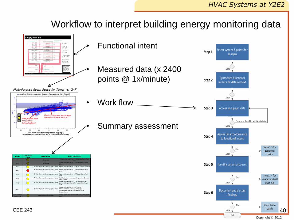
Workflow to interpret building energy monitoring data
• Functional intent
• Measured data (x 2400
points @ 1x/minute)
• Work flow
• Summary assessment
40
Select system & points for analysis
Synthesize functional intent and data context
Access and graph data
Assess data conformance to functional intent
Identify potential causes
Document and discuss findings
Step 1
Step 4
Step 2
Step 3
Step 5
Step 6
End
All Ok
All Ok
All Ok
All Ok
All Ok
All Ok
Steps 1-5 to Clarify
Else
ElseSteps 1-4 for
satisfactory fault diagnosis
Steps 1-3 for additional
clarity
Else
Else repeat Step 3 for additional clarity
Copyright 2012
HVAC Systems at Y2E2
CEE 243
Reading
• ACCO engineered systems, HVAC Sequences of
Operation for Stanford SEQ2 Environment and Energy
Building, 2007
• Abram, T., J. Kunz, J. O’Donnell, and M. Garr, Energy
Performance Analyses of a Santa Clara County Facility
by CEE243 Student Groups, CIFE Technical Report
#TR204, 2011
41
Copyright 2012
HVAC Systems at Y2E2
CEE 243
Homework
• For an assigned system, compare
patterns between different years (2008,
2009, 2010)
• Classify pattern (red/yellow/green) re
assumed functional intent
42
Copyright 2012
HVAC Systems at Y2E2
CEE 243
Big idea
• Modern energy management systems include a
combination of passive and active control of energy
distribution
– Passive: constant (volume/flow)
– Active: variable (volume/flow) under computer
control
• Based on If-then conditional control rules of
general form
If setpoint value out of range and
Other conditions met
Then adjust control variable value
43