Embed Size (px)
Citation preview

1
Y-Mahe Lock Trochanteric Nail System Solution without Compromise!
Surgical Technique Titanium & Steel Nail System
Revision: 23.02.2011

2
Introduction Mahe Medical GmbH is growing worldwide as a medical device manufacturing company, manufactures a wide range of trauma – orthopedic implants. Mahe Medical GmbH products provide top quality and usability while the offered services and support make Mahe Medical GmbH products fully customer orientated. Mahe Medical GmbH puts special emphasis on innovation, our R&D department works in tight cooperation with international clinical experts in order to develop high quality implants which fit better for patient needs. We are proud to introduce one of our leading innovation, the Y-Mahe_Lock Trochanteric Nail System in Titanium & Steel. On the 240mm long nail the distal shaft of the nail is grooved, which helps at the insertion of the nail and its flexibility prevents the erosion of the cortical bone at the tip of the nail implant, which is well known source of pain and fractures. The basic implantation instruments are coming in a high quality perforated stainless steel tray set ( 2 pcs. ) with lids, where all instruments are assembled in plastic inlays to make the surgery fast and efficient. Every instrument can be disassembled into pieces, and the stainless steel trays and lids make it easy to clean. Colour coded parts are very useful to find the next step without any mistakes and difficulties.
Corporate Philosophy Mahe designs, develops and manufactures implants for use in specific implant system developed by its customers. We make orthopaedic implants used primarily in knee orthopaedic and hip implant systems, also provides a broad range of trauma implants, dental implants.Surgical instruments used in hip, knee and shoulder reconstruction procedures, as well as in spinal, trauma and other implant procedures. Mahe designs, develops and manufactures implant-specific and procedure-specific instruments. Mahe does manufacture general surgical instruments. Mahe innovative and exciting product portfolio is updated and expanded in line with technological advances to satisfy the current and future needs of both patients and healthcare professionals. Mahe is committed to playing our part in achieving improved healthcare outcomes worldwide.

3
Design & Features Necessary Components: Screw plug Fixation screw
Lag screws length: 75mm-145mm
Y-Mahe_Lock nail implants short Solid/cannulated Angle: 130°/135° Diameter: 11-12mm Length: 180-240mm Y-Mahe_Lock nail implants long Solid/cannulated Angle: 130°/135° Diameter: 10mm Length: 320-420mm Distal locking screws Thread Diameter: 4.9mm Length: 20-80mm (<2mm>); 40-100mm (<5mm>) Grooved design at the 240mm short nail for prevention of cortical bone erosion Aiming assistance for increased implantation accuracy

4
Basic Recommended Instruments
Set-94500-00000 Basic Nail Instrument Set
TRAY-94500-10000 Tray set 2 pcs. ( steel trays ) 1 pcs INS-94500- 00100 Radiolucent aiming device ( carbon ) 1 pcs INS-94500- 00201 Aiming device attachment 130° ( carbon ) 1 pcs INS-94500- 00203 Aiming device clamp screw 2 pcs INS-94500- 00301 Aiming device attachment 135° ( carbon ) 1 pcs INS-94500- 00400 Aiming device fixation screw 1 pcs INS-94500- 00500 Nail adapter screw 1 pcs INS-94500- 00600 T-wrench for dynamic screw 1 pcs INS-94500- 00700 Threaded coupling screw for dynamic screw 1 pcs INS-94500- 00800 Compressing device 1 pcs INS-94500- 00900 Curved cannulated reamer ( awl ) 1 pcs INS-94500- 01000 Hammer guide shaft 1 pcs INS-94500- 01004 Removal fixation device 1 pcs INS-94500- 01100 Slide hammer 1 pcs INS-94500- 01200 Soft tissue protector for dynamic screw 16/13 mm 1 pcs INS-94500- 01300 Drill sleeve for guiding wire 13/3 mm 1 pcs INS-94500- 01400 Reamer for dynamic screw 12,8 mm 1 pcs INS-94500- 01500 Dynamic screw reamer 8 mm, cannulated 1 pcs INS-94500- 01600 Drill guide for dynamic screw reamer 12,8/8 mm 1 pcs INS-94500- 01700 Gauge for dynamic screw 1 pcs INS-94500- 01800 Soft tissue protector for locking screw 10/8 mm 1 pcs INS-94500- 01900 Drill sleeve for distal locking drill 8/4 mm 1 pcs INS-94500- 02000 Depth gauge for locking screw 1 pcs INS-94500- 02100 3,5mm hex.x200 mm hexagonal screw driver 1 pcs INS-94500- 02200 10mm hex.x205mm hexagonal screw driver shaft 1 pcs INS-94500- 02300 Cardan screw driver shaft 4.0mm hex. with QC 1 pcs INS-94500- 02400 Cardan for device removal 1 pcs INS-94500- 02501 Hammer guide head 1 pcs INS-94500- 02600 Screw driver shaft 3.5mm hex. with QC 310 mm 1 pcs INS-15000- 35400 K - wire 3,5mmx400 mm 1 pcs INS-15020- 30400 K - wire 3,0mmx400 mm with threaded tip 4 pcs INS-99000- 00004 Wrench width flats 12 mm 1 pcs INS-99010- 32350 Twist drill 3,2mmx350 mm 1 pcs INS-99010- 40310 Twist drill 4,0mmx310 mm 1 pcs INS-99000- 00006 Universal T-handle with quick coupling 1 pcs
5
Implant Steel Trays with LID
TRAY-94500-10001 Tray for long nails (steel tray)
TRAY-94500-10002 Tray for short nails (steel tray)
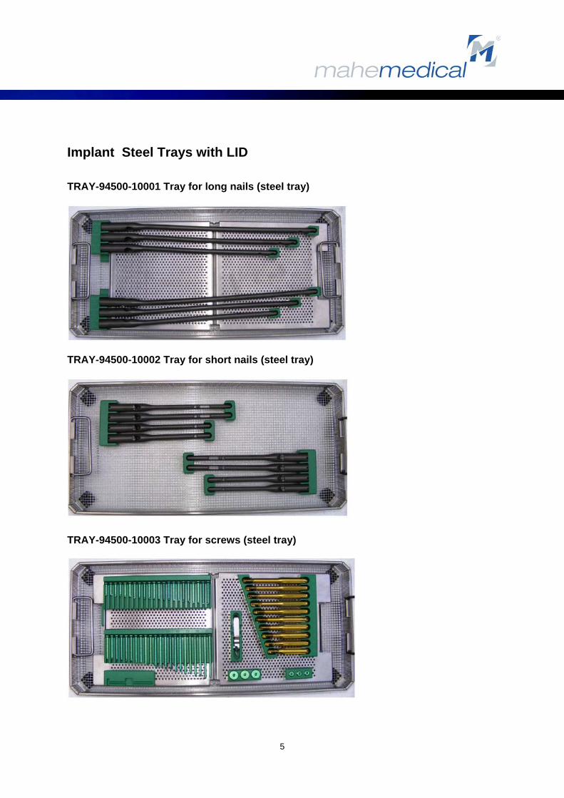
TRAY-94500-10003 Tray for screws (steel tray)

6
Surgical Technique 1. Preoperative planning
Preopretaive X-ray of the uninjured distal Femoral is used to estimate proper nail Diameter, nail length, and CCD-angle ( caput-collum-diaphyseal angle ). 2. Patient positioning and reposition
With the patient supine, abduct the unaffected limb while adducting the trunk and the affected extremity and flex the affected hip 15°. Apply traction with a foot holder and rotate the foot to obtain correct rotational alignment. Orthopedic surgical table is recommended!
3. Skin incision Make an approx. 5cm long skin incision proximal to the greater trochanter. Incise the fascia of the gluteus maximus, identify the subfascial plane and palpate the trochanteric fossa. Fluoroscopic control is advised! The image intensifier must be in a standard position for a-p –and lateral view. Pay special attention, important step.
Numbers in trays after the after the instrument names refer to list number in the instrument trays.

7
4. Determining the entry point
With a 3x400mm threaded Kirschner wire (14.) find the trochanteric fossa. The tip of the pin should be in the midplane of the femoral in both anteroposterior and lateral views. Under fluoroscopic control insert the Kirschner wire into the medullary canal. 5. Opening the femoral canal
Insert the cannulated 17.6mm curved cannulated reamer – awl (6.) over the Kirschner wire to enlarge the entry portal. Ream the proximal femoral until the reamer sink into it. 6. Assembling the instruments
Attach the intramedullary nail to the radiolucent aiming device (3.) with the nail adapter screw (5.). Connect the nail with the 10mm hexagonal screwdriver (27,29). Depending on the CCD angle of nail implant (130°/135°) mount the correct aiming device attachment (1.,2.) aiming device fixation screw. Drive the fixation screw into the nail, but the tip of the screw should not hinder the rotation of the dynamic screw!

8
7. Checking the correct assembling
Put into the dynamic screw hole the yellow soft tissue protector (31.) and reamer (37.). Put into the distal hole the green soft tissue protector (24.), drill sleeve (25.) and dia. 4.0mm twist drill ( 35.). 8. Inserting the nail implant
If solid nail is used, remove the Kirschner wire, If it cannulated, the nail should be inserted over the wire. Insert the nail carefully by hand until axis of the dynamic screw hole reaches the center of the femoral neck. If resistance is encountered, stop and withdraw the nail implant and push it with slight twisting, or use a smaller nail diameter. Never hit the aiming device. In difficult cases you may use the extraction device to support insertion. 9. X-ray evaluation Put a Kirschner wire (14.) into the proximal hole of the aiming device. It is shadow in the lateral view should be in the center of the femoral neck. The lateral groove of the aiming device is parallel to the dynamic head screw. 10. Skin incision at the dynamic screw
Put the yellow soft tissue protector (31.) and drill sleeve (26.) into the aiming device, incise the skin and fascia and push the drill sleeves to the bone. With the clamp screw on the aiming device (10.) fix the position.

9
11. Predrill the guide wire
Drill through the cortical bone with the yellow dia. 3.2mm twist drill (34.) The treaded Kirschner guide wire may damage or bend by the cortical bone, therefore is im- portant to rough-drill it by the termed twist drill.
12. Insertion of the guide wire
Insert the dia. 3.0x400mm threaded Kirschner guide wire (22.) into the femoral head to a level approximately 5mm below the subchondral bone. Confirm the position of the guide wire within the head with a-p and lateral view. 13. Length measurement
Measure the length of the dynamic screw on the guide wire with the length gauge (33.).
Verify that drill sleeves are against the bone!
14. Reaming for dynamic screw Remove the yellow drill sleeve and insert the dia. 12.8mm reamer (37.) over the guide wire, drill through the nail.
If the reamer get stuck, check the fixation screw in the nail, if the fixation screw driven too deeply it can block and damage the reamer. You may drill forwards (!) while extracting the drill in order to keep the guide wire in it is place!

10
15. Predrilling for dynamic screw Put the red drill guide (32.) over the red drill (21.) from its back and set its fixation sleeve to the measured dynamic screw length. Drill until the stop. The T-handle (37.) may be used for for drilling.
16. Assembling wrench for dynamic screw
Drive the threaded stem (8.) through the T-wrench (7.) from above, drive the compression device (4.) from below. Set the dynamic screw with the threaded stem.
17. Inserting dynamic screw
Insert the dynamic screw over the guide wire. The tip of the screw should be approximately 5mm before the tip of the guide wire. The compression device (4.) may be used to com- press the fracture. 18. Rotational stabilization Use the cardan screwdriver (30.) with the T-handle (37.) to tighten the fixation screw in the nail. The tip of the fixation screw should be in a groove of the dynamic screw to prevent the rotation. Unscrew the fixation screw by a quarter revolution in order to dynamize the fixation!

11
19. Removing the drill sleeves Remove the dynamic screw wrench by twisting out the threaded stem. Remove the guide wire. Remove the yellow soft tissue protector by re- leasing the clamp screw on the aiming device. 20. Distal interlocking
There is a round and an oval dynamic hole on the distal part of the nail to produce static or dynamic interlocking. Put the green soft tissue protector (24.) and drill sleeve (25.) into the aiming device attachment, incise the skin, push the drill sleeve to the bone and fix the position with the clamp screw (10.) with the green dia. 4.0mm twist drill (35.) drill trough the nail and opposite cortex. Read the length on the drill or use the depth gauge (33.) to determine the screw length. Interlock the nail with the dia. 4.9mm locking screw, obtain a final X-ray view to confirm and make sure the satisfactory of the locking screw placement. 21. Closure
Remove the aiming device by releasing the nail adapter screw (5.) with the 10mm hexagonal screwdriver (29.). Close the proximal part of the nail with a screw plug, tighten it with the cardan screwdriver (27.,30.).

12
Nail Removal
1. Removal the screw plug
Remove the screw plug with the cardan Screwdriver (27., 30.).
2. Open the fixation screw
Open and return the fixation screw with the same screwdriver (27., 30.) as much to remove the dynamic screw, complete removal is not necessary.
3. Removing the dynamic screw
Drive the threaded stem (8.) through the T-wrench (7.) from above. Attach the wrench with the dynamic screw, which can be removed by counterclockwise turning.
4. Attaching the removal device for nail
Drive the nail adapter screw (5.) into the nail, attach the cardan rod (38.) to it is internal thread.

13
5. Removing the distal interlocking screws
Remove all the distal interlocking screws with the screwdriver (28.).
6. Assembling the extraction device
Put the slide hammer (11.) over the hammer guide shaft (12.), close its end with the hammer guide head (13.) and secure it with the 12mm wrench (36.).
7. Extraction of the nail
Put the extraction device fixation sleeve (39.) over the cardan rod (38.) and assemble it with the hammer shaft. The nail implant can be extracted with the slide hammer.

14
Y-Mahe_Lock, Short Trochanteric Titanium Nails Raw material specification: titanium alloy according to ISO 5832-3 Ti-6Al-4V
Cannulated Nails
Solid Nails Ø Diam. mm Length mm
Angle - Degree (°)
REF.: REF.:
NA-34510-
11180
NA-34500-11180 11 180 130°
NA-34510-11200
NA-34500-11200
11 200 130°
NA-34510-11220
NA-34500-11220
11 220 130°
NA-34510-11240
NA-34500-11240
11 240 130°
NA-34530-11180
NA-34520-11180
11 180 135°
NA-34530-11200
NA-34520-11200
11 200 135°
NA-34530-11220
NA-34520-11220
11 220 135°
NA-34530-11240
NA-34520-11240
11 240 135°
NA-34510-12180
NA-34500-12180
12 180 130°
NA-34510-12200
NA-34500-12200
12 200 130°
NA-34510-12220
NA-34500-12220
12 220 130°
NA-34510-12240
NA-34500-12240
12 240 130°
NA-34530-12180
NA-34520-12180
12 180 135°
NA-34530-12200
NA-34520-12200
12 200 135°
NA-34530-12220
NA-34520-12220
12 220 135°
NA-34530-12240
NA-34520-12240
12 240 135°

15
Y-Mahe_Lock, Short Trochanteric Steel Nails Raw material specification: steel alloy according to ISO 5832-1 Cannulated Nails
Solid Nails Ø Diam. mm Length mm
Angle - Degree (°)
REF.: REF.:
NA-14510-11180
NA-14500-11180
11 180 130°
NA-14510-11200
NA-14500-11200
11 200 130°
NA-14510-11220
NA-14500-11220
11 220 130°
NA-14510-11240
NA-14500-11240
11 240 130°
NA-14530-11180
NA-14520-11180
11 180 135°
NA-14530-11200
NA-14520-11200
11 200 135°
NA-14530-11220
NA-14520-11220
11 220 135°
NA-14530-11240
NA-14520-11240
11 240 135°
NA-14510-12180
NA-14500-12180
12 180 130°
NA-14510-12200
NA-14500-12200
12 200 130°
NA-14510-12220
NA-14500-12220
12 220 130°
NA-14510-12240
NA-14500-12240
12 240 130°
NA-14530-12180
NA-14520-12180
12 180 135°
NA-14530-12200
NA-14520-12200
12 200 135°
NA-14530-12220
NA-14520-12220
12 220 135°
NA-14530-12240
NA-14520-12240
12 240 135°

16
Y-Mahe_Lock, Long Trochanteric Titanium Nails Raw material specification: titanium alloy according to ISO 5832-3 Ti-6Al-4V
Cannulated Nails
Solid Nails Ø Diam. mm Length mm
Angle - Degree (°)
REF.: REF.: RIGHT
NA-34610-34130
NA-34630-34130
10 340 130°
NA-34610-36130
NA-34630-36130
10 360 130°
NA-34610-38130
NA-34630-38130
10 380 130°
NA-34610-40130
NA-34630-40130
10 400 130°
NA-34610-42130
NA-34630-42130
10 420 130°
NA-34610-34135
NA-34630-34135
10 340 135°
NA-34610-36135
NA-34630-36135
10 360 135°
NA-34610-38135
NA-34630-38135
10 380 135°
NA-34610-40135
NA-34630-40135
10 400 135°
NA-34610-42135
NA-34630-42135
10 420 135°
Cannulated Nails
Solid Nails Ø Diam. mm Length
mm Angle - Degree
(°)
REF.: REF.: LEFT
NA-34600-34130
NA-34620-34130
10 340 130°
NA-34600-36130
NA-34620-36130
10 360 130°
NA-34600-38130
NA-34620-38130
10 380 130°
NA-34600-40130
NA-34620-40130
10 400 130°
NA-34600-42130
NA-34620-42130
10 420 130°
NA-34600-34135
NA-34620-34135
10 340 135°
NA-34600-36135
NA-34620-36135
10 360 135°
NA-34600-38135
NA-34620-38135
10 380 135°
NA-34600-40135
NA-34620-40135
10 400 135°
NA-34600-42135
NA-34620-42135
10 420 135°

17
Y-Mahe_Lock, Long Trochanteric Steel Nails Raw material specification: steel alloy according to ISO 5832-1
Cannulated Nails
Solid Nails Ø Diam. mm Length mm
Angle - Degree (°)
REF.: REF.: RIGHT
NA-14610-34130
NA-14630-34130
10 340 130°
NA-14610-36130
NA-14630-36130
10 360 130°
NA-14610- 38130
NA-14630-38130 10 380 130°
NA-14610-40130
NA-14630-40130
10 400 130°
NA-14610-42130
NA-14630-42130
10 420 130°
NA-14610-34135
NA-14630-34135
10 340 135°
NA-14610-36135
NA-14630-36135
10 360 135°
NA-14610-38135
NA-14630-38135
10 380 135°
NA-14610-40135
NA-14630-40135
10 400 135°
NA-14610-42135
NA-14630-42135
10 420 135°
Cannulated Nails
Solid Nails Ø Diam. mm Length mm
Angle - Degree (°)
REF.: REF.: LEFT
NA-14600-34130
NA-34620-34130
10 340 130°
NA-14600-36130
NA-34620-36130
10 360 130°
NA-14600-38130
NA-34620-38130
10 380 130°
NA-14600-40130
NA-34620-40130
10 400 130°
NA-14600-42130
NA-34620-42130
10 420 130°
NA-14600-34135
NA-34620-34135
10 340 135°
NA-14600-36135
NA-34620-36135
10 360 135°
NA-14600-38135
NA-34620-38135
10 380 135°
NA-14600-40135
NA-34620-40135
10 400 135°
NA-14600-42135
NA-34620-42135
10 420 135°

18
Y-Mahe_Lock Titanium & Steel Dynamic Lag Screws used for Trochanteric Y - Nails Raw material specification: titanium alloy according to ISO 5832-3 Ti-6Al-4V Raw material specification: steel alloy according to ISO 5832-1 Important Technical Dimension:
- Thread Diameter = 12.6mm - Core Diameter = 8.0mm - Pitch = 3.0mm
REF.: Titanium Lag Screws
Length mm REF.: Steel Lag Screws
Length mm
LS-32700-12075
75 LS-12700-12075 75
LS-32700-12080
80 LS-12700-12080 80
LS-32700-12085
85 LS-12700-12085 85
LS-32700-12090
90 LS-12700-12090 90
LS-32700-12095
95 LS-12700-12095 95
LS-32700-12100
100 LS-12700-12100 100
LS-32700-12105
105 LS-12700-12105 105
LS-32700-12110
110 LS-12700-12110 110
LS-32700-12115
115 LS-12700-12115 115
LS-32700-12120
120 LS-12700-12120 120
LS-32700-12125
125 LS-12700-12125 125
LS-32700-12130
130 LS-12700-12130 130
LS-32700-12135
135 LS-12700-12135 135
LS-32700-12140
140 LS-12700-12140 140
LS-32700-12145
145 LS-12700-12145 145

19
Y-Mahe_Lock Titanium & Steel Fixation Screw used for Trochanteric Y - Nails Raw material specification: titanium alloy according to ISO 5832-3 Ti-6Al-4V Raw material specification: steel alloy according to ISO 5832-1
REF.: Titanium Fixation Screw
REF.: Steel
Fixation Screw
LS-32401-09020 LS-12401-09020 Y-Mahe_Lock Titanium & Steel Screw Plug used for Trochanteric Y - Nails Raw material specification: titanium alloy according to ISO 5832-3 Ti-6Al-4V Raw material specification: steel alloy according to ISO 5832-1
REF.: Titanium
Screw Plug
REF.: Steel
Screw Plug
LS-32400-17016 LS-12400-17016

20
Y-Mahe_Lock Titanium & Steel Dynamic Locking Screws Diameter 4.9mm used for Trochanteric Y - Nails Raw material specification: titanium alloy according to ISO 5832-3 Ti-6Al-4V Raw material specification: steel alloy according to ISO 5832-1
Important Technical Dimension:
- Thread Diameter = 4.9 mm - Core Diameter = 4.2 mm - Head Diameter = 8.0 mm - Pitch = 2.75mm - Hex. width = 3.5 mm
REF.: Titanium Locking Screws
Length mm REF.: Steel Locking Screws
Length mm
LS-32200-49020 20 LS-12200-49020 20 LS-32200-49022 22 LS-12200-49022 22 LS-32200-49024 24 LS-12200-49024 24 LS-32200-49026 26 LS-12200-49026 26 LS-32200-49028 28 LS-12200-49028 28 LS-32200-49030 30 LS-12200-49030 30 LS-32200-49032 32 LS-12200-49032 32 LS-32200-49034 34 LS-12200-49034 34 LS-32200-49036 36 LS-12200-49036 36 LS-32200-49038 38 LS-12200-49038 38 LS-32200-49040 40 LS-12200-49040 40 LS-32200-49042 42 LS-12200-49042 42 LS-32200-49044 44 LS-12200-49044 44 LS-32200-49045 45 LS-12200-49045 45 LS-32200-49046 46 LS-12200-49046 46 LS-32200-49048 48 LS-12200-49048 48 LS-32200-49050 50 LS-12200-49050 50 LS-32200-49052 52 LS-12200-49052 52 LS-32200-49054 54 LS-12200-49054 54 LS-32200-49055 55 LS-12200-49055 55 LS-32200-49056 56 LS-12200-49056 56 LS-32200-49058 58 LS-12200-49058 58 LS-32200-49060 60 LS-12200-49060 60 LS-32200-49062 62 LS-12200-49062 62 LS-32200-49064 64 LS-12200-49064 64 LS-32200-49065 65 LS-12200-49065 65 LS-32200-49066 66 LS-12200-49066 66 LS-32200-49068 68 LS-12200-49068 68 LS-32200-49070 70 LS-12200-49070 70 LS-32200-49072 72 LS-12200-49072 72 LS-32200-49074 74 LS-12200-49074 74 LS-32200-49075 75 LS-12200-49075 75 LS-32200-49076 76 LS-12200-49076 76 LS-32200-49078 78 LS-12200-49078 78 LS-32200-49080 80 LS-12200-49080 80 LS-32200-49085 85 LS-12200-49085 85 LS-32200-49090 90 LS-12200-49090 90 LS-32200-49095 95 LS-12200-49095 95 LS-32200-49100 100 LS-12200-49100 100

21
Y-Mahe_Lock Trochanteric Nails System
Solution without Compromise!
mahe medical gmbH Phone +49 7465 9275-0 Friedrich-Wöhler-Straße 10 Fax +49 7465 9275-29 78576 Emmingen, Germany [email protected] www.mahe-med.de