Embed Size (px)
Citation preview
http://support.automation.siemens.com/WW/view/en/73257075
FAQ 12/2014
How Can You Integrate aDrive into the TIA Portal viathe Device Master File (GSD)?SIMATIC S7-1500 / TIA Portal from V12 SP1

Question
Integrating a Drive via the GSD FileEntry-ID: 73257075, V1.2, 12/2014 2
Siem
ens
AG20
14Al
lrig
hts
rese
rved
This entry is from the Siemens Industry Online Support. The general terms of use(http://www.siemens.com/terms_of_use) apply.
Securityinforma-tion
Siemens provides products and solutions with industrial security functions thatsupport the secure operation of plants, solutions, machines, equipment and/ornetworks. They are important components in a holistic industrial securityconcept. With this in mind, Siemens’ products and solutions undergo continuousdevelopment. Siemens recommends strongly that you regularly check forproduct updates.
For the secure operation of Siemens products and solutions, it is necessary totake suitable preventive action (e.g. cell protection concept) and integrate eachcomponent into a holistic, state-of-the-art industrial security concept. Third-partyproducts that may be in use should also be considered. For more informationabout industrial security, visit http://www.siemens.com/industrialsecurity.
To stay informed about product updates as they occur, sign up for a product-specific newsletter. For more information, visithttp://support.automation.siemens.com.
QuestionHow can you integrate a drive into the TIA Portal via the device master file (GSD)?
AnswerThe instructions and notes listed in this document provide a detailed answer to thisquestion.
Table of Contents
Integrating a Drive via the GSD FileEntry-ID: 73257075, V1.2, 12/2014 3
Siem
ens
AG20
14Al
lrig
hts
rese
rved
Table of contents1 Motivation ........................................................................................................... 5
1.1 Motion control with the SIMATIC S7-1500 ........................................... 51.2 The SINAMICS Startdrive STEP 7 option ............................................ 51.3 Commissioning software for the drive .................................................. 71.4 Software used for this documentation .................................................. 7
2 GSD Files in the TIA Portal ............................................................................... 8
2.1 Existing GSD files ................................................................................. 82.2 Adding additional GSD files ................................................................. 82.2.1 Obtaining the GSD files ........................................................................ 82.2.2 Integrating the GSD files ...................................................................... 9
3 Connecting a Drive to the S7-1500 ................................................................ 11
3.1 Selecting the drive from the hardware catalog ................................... 113.2 Establishing the bus connection ......................................................... 123.2.1 PROFIBUS DP fieldbus ...................................................................... 123.2.2 PROFINET I/O fieldbus ...................................................................... 15
4 Establishing the Communication Connection .............................................. 18
4.1 Telegram selection ............................................................................. 184.1.1 Drive telegrams that can be used with the SIMATIC S7-1500 ........... 184.1.2 Selection aid for the drive telegrams .................................................. 194.1.3 Supplementary telegrams of the SINAMICS S drive family ............... 204.2 Connection via PROFIBUS DP .......................................................... 204.3 Connection via PROFINET I/O .......................................................... 23
5 Setting Isochronous Mode.............................................................................. 27
5.1 PROFIBUS DP ................................................................................... 275.1.1 Basics and definition .......................................................................... 275.1.2 Settings in the TIA Portal.................................................................... 275.2 PROFINET I/O ................................................................................... 295.2.1 Basics and definition .......................................................................... 295.2.2 Settings in the TIA Portal.................................................................... 32
6 Motion Control Functions of the S7-1500 ..................................................... 37
6.1 Technology objects ............................................................................ 376.2 Selecting the drive on the technology object...................................... 386.3 Controlling the axis from the user program ........................................ 40
7 STARTER Commissioning Software ............................................................. 43
7.1 Working with drives ............................................................................ 437.2 Creating a drive unit ........................................................................... 447.2.1 PROFIBUS DP ................................................................................... 447.2.2 PROFINET I/O ................................................................................... 457.3 Creating the drives ............................................................................. 467.3.1 Adapting the communication message frames .................................. 48
8 Glossary ........................................................................................................... 50
9 Appendix .......................................................................................................... 55
9.1 Characteristic feature of SIMODRIVE drives ..................................... 559.1.1 Basic information ................................................................................ 559.1.2 Connecting the drive to the S7-1500 .................................................. 559.1.3 Establishing the communication connection ...................................... 569.1.4 Selecting the drive on the technology object...................................... 579.1.5 Checking the drive connection via the technology object .................. 59
Table of Contents
Integrating a Drive via the GSD FileEntry-ID: 73257075, V1.2, 12/2014 4
Siem
ens
AG20
14Al
lrig
hts
rese
rved
10 References ....................................................................................................... 61
10.1 Bibliography ........................................................................................ 6110.2 Internet links ....................................................................................... 62

1 Motivation1.1 Motion control with the SIMATIC S7-1500
Integrating a Drive via the GSD FileEntry-ID: 73257075, V1.2, 12/2014 5
1 Motivation1.1 Motion control with the SIMATIC S7-1500
In each CPU, the SIMATIC S7-1500 features technology functions that allow easycontrol of drives and therefore enable the user to implement motion controlapplications quickly and easily.As shown in the figure below, all SIMATIC S7-1500 CPUs have a PROFINET portthat can be used to connect drives to the controller. For some CPUs, for examplethe CPU 1516-3 PN/DP, you also have the option to connect PROFIBUS devices.The connection of HMI devices and drives of the SINAMICS family is shown hereas an example.
Figure 1-1 Connecting drives to the SIMATIC S7-1500
1.2 The SINAMICS Startdrive STEP 7 option
If the SINAMICS Startdrive STEP 7 option package has been installed in theTotally Integrated Automation Portal (TIA Portal), SINAMICS G110 and G120drives can be configured and commissioned directly in the TIA Portal using theSINAMICS Startdrive option.This is not possible for other drives of the SINAMICS family and third-party drives.However, these drives can still be used in the TIA Portal and controlled via theSIMATIC S7-1500 user program.

1 Motivation1.2 The SINAMICS Startdrive STEP 7 option
Integrating a Drive via the GSD FileEntry-ID: 73257075, V1.2, 12/2014 6
Figure 1-2 SINAMICS Startdrive STEP 7 option
Drives that do not yet exist in the Totally Integrated Automation Portal areintegrated with the aid of device master files, so-called GSD or GSDML files. Theaim of this documentation is to provide a detailed explanation of the integration anduse of these GSD or GSDML files.
Note Throughout the rest of this document, “GSD file” is used synonymously for theterms “GSD file” for PROFIBUS and “GSDML file” for PROFINET
Depending on how the drives were integrated into the TIA Portal, drive selection inthe hardware configuration must be made from different folders of the hardwarecatalog.
Figure 1-3 TIA Portal hardware catalog
Drives that were integrated intothe TIA Portal via GSD files are
entered here.
Drives that can be configuredand parameterized using theSINAMICS Startdrive STEP 7
option are entered here.

1 Motivation1.3 Commissioning software for the drive
Integrating a Drive via the GSD FileEntry-ID: 73257075, V1.2, 12/2014 7
Note Even without installing the SINAMICS Startdrive STEP 7 option, various drives ofthe SINAMICS S and SINAMICS G family have already been integrated into theTotally Integrated Automation Portal (TIA Portal) as device master files and canbe used in projects.
1.3 Commissioning software for the driveIf the desired drive is integrated via the GSD file and can therefore not beconfigured and parameterized or commissioned using the SINAMICS StartdriveSTEP 7 option, the drive must be commissioned using additional commissioningsoftware. The same applies to the use of third-party drives.For drives of the SINAMICS S family and drives of the SINAMICS G family thatcannot be configured using the SINAMICS Startdrive STEP 7 option, theSINAMICS MICROMASTER STARTER commissioning tool can be used forcommissioning.
Note In order to use the drive in conjunction with the SIMATIC S7-1500, theconfiguration in the drive made using the commissioning software must matchthe configuration in the Totally Integrated Automation Portal (TIA Portal).
1.4 Software used for this documentationThis document was created using the software listed in the following table.However, it can also be applied to other commissioning tools and software versions– even from third-party suppliers.
Table 1-1 Software used
Software Version Remark
Totally IntegratedAutomation Portal
TIA Portal V13with STEP 7
ProfessionalV13WinCC BasicV13
The Totally IntegratedAutomation Portal (TIA Portal)engineering framework from theSiemens Industry AutomationDivision for the configuration,programming, commissioningand servicing of Siemensprogrammable controllers anddrive systems.
SINAMICSMICROMASTERSTARTER
V4.4 HF3 Commissioning software tocommission all drives of theSINAMICS family for easyconfiguration andcommissioning of drivecomponents – menu-promptedand graphically supported.
Note For the procedure described in this documentation, it is not necessary to installthe SINAMICS Startdrive STEP 7 option in the Totally Integrated AutomationPortal (TIA Portal).

2 GSD Files in the TIA Portal2.1 Existing GSD files
Integrating a Drive via the GSD FileEntry-ID: 73257075, V1.2, 12/2014 8
2 GSD Files in the TIA Portal2.1 Existing GSD files
The drives that have already been supplied with the Totally Integrated AutomationPortal (TIA Portal) via device master files (GSD files) can be selected in thehardware catalog in “Other field devices”. This folder includes GSD files for drivesof the PROFIBUS DP and PROFINET I/O fieldbus variants.
Figure 2-1 TIA Portal hardware catalog
2.2 Adding additional GSD files
If the desired drive unit does not exist in the TIA Portal with the appropriatefirmware version, the device master file (GSD file) can subsequently be installed inthe Totally Integrated Automation Portal (TIA Portal).
2.2.1 Obtaining the GSD files
The device master file (GSD file) required for the desired firmware version can beobtained in two different ways.
The field devices that havebeen integrated into the TIA
Portal via GSD files areentered here.
The hardware catalog includesdevices for both the
PROFINET I/O fieldbus …
… and the PROFIBUS DPfieldbus.

2 GSD Files in the TIA Portal2.2 Adding additional GSD files
Integrating a Drive via the GSD FileEntry-ID: 73257075, V1.2, 12/2014 9
Download from Siemens Industry Online SupportIn Siemens Industry Online Support, different download pages offer the devicemaster files (GSD files) for the respective SINAMICS drives: PROFINET I/O fieldbus (GSDML files): see \7\. PROFIBUS DP fieldbus (GSD files): see \8\.
Drives of the SINAMICS S family: Copying from the CF card of the Control UnitIf the CF card required for operation already exists with the appropriate firmwareversion of the SINAMICS S, the necessary GSD file can also be copied directlyfrom the CF card.
On the CF card of the Control Unit, the device master file (GSDfile) can be found in the following directory:
“SIEMENS > SINAMICS > DATA > CFG”
Note Copy all files in this directory – including the image file (BMP) – to a folder fromwhich you want to integrate the device master file (GSD file) into the TotallyIntegrated Automation Portal (TIA Portal).
Drives of the SINAMICS G family: Reading out of the Control UnitIf the desired drive or the Control Unit of the drive of the SINAMICS G familyalready exists and if you have a SINAMICS card or a blank SIMATIC memory cardof the S7-1500 to hand, the device master file (GSD file) can also be read out ofthe Control Unit.
For example, for the CU240E-2 Control Unit proceed asfollows to read out the device master file: Insert the memory card into the Control Unit Set the p0804 parameter to the value 12 Remove the memory card from the Control Unit Using the memory card, you can now transfer the
device master file to the programmer for installationin the Totally Integrated Automation Portal (TIAPortal).
Note For other hardware components or firmware versions of theSINAMICS G family, the procedure may differ. Please refer to theappropriate manuals or Getting Started.
2.2.2 Integrating the GSD files
The device master file of the desired firmware version of the drive can be importedto the Totally Integrated Automation Portal (TIA Portal) using the “Options > Installgeneral station description file (GSD)” menu option.
2 GSD Files in the TIA Portal2.2 Adding additional GSD files
Integrating a Drive via the GSD FileEntry-ID: 73257075, V1.2, 12/2014 10
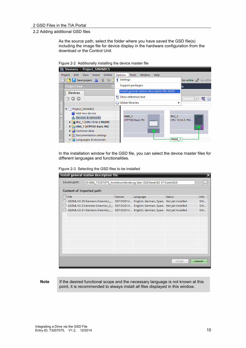
As the source path, select the folder where you have saved the GSD file(s)including the image file for device display in the hardware configuration from thedownload or the Control Unit.
Figure 2-2 Additionally installing the device master file
In the installation window for the GSD file, you can select the device master files fordifferent languages and functionalities.
Figure 2-3 Selecting the GSD files to be installed
Note If the desired functional scope and the necessary language is not known at thispoint, it is recommended to always install all files displayed in this window.

3 Connecting a Drive to the S7-15003.1 Selecting the drive from the hardware catalog
Integrating a Drive via the GSD FileEntry-ID: 73257075, V1.2, 12/2014 11
3 Connecting a Drive to the S7-1500The desired drive can now be integrated into the project. The aim of this example isto show the connection of a SINAMICS S120 to the SIMATIC S7-1500.
3.1 Selecting the drive from the hardware catalog
For the SIMATIC S7-1500 to which the SINAMICS S120 is to be connected, openthe “Device configuration” and go to the “Network view”.On the right side of the TIA Portal, open the “Hardware catalog”. The drivesintegrated into the TIA Portal via the device master file (GSD file) can then befound in the hardware catalog in “Other field devices”.Select the desired drive from the hardware catalog and use drag-and-drop to movethe item from the editing window to the Network view. This creates the drive in theproject. Detailed information on the selected drive is available at the bottom of thehardware catalog in “Information”.
Figure 3-1 Integrating the drive into the device configuration
Open thedevice configuration ofthe SIMATIC S7-1500. Use drag-and-drop to
move the desired driveto the work window of
the Network view.Select the
Network view to insertthe drive.

3 Connecting a Drive to the S7-15003.2 Establishing the bus connection
Integrating a Drive via the GSD FileEntry-ID: 73257075, V1.2, 12/2014 12
Note When selecting the desired drive, make sure that you select the correct fieldbustechnology. Otherwise, it is not possible to establish the bus connection betweenthe SIMATIC S7-1500 and the drive with the desired fieldbus.
3.2 Establishing the bus connectionIf the drive has been inserted into the project, the bus connection between theSIMATIC S7-1500 and the newly inserted drive can be established in the “Networkview”.
Note Initially, the bus connection defines the communication partner of the SIMATICS7-1500 or the drive. At this point, the data to be exchanged between theSIMATIC S7-1500 and the drive is not yet configured. The bus connection onlycreates the option to exchange data and defines the physical interface.
3.2.1 PROFIBUS DP fieldbus
To establish the connection between the SIMATIC S7-1500 and the drive via thePROFIBUS DP fieldbus, click on the PROFIBUS port of the drive in the TIA Portaland connect this port to the PROFIBUS port of the SIMATIC S7-1500 whilekeeping the left mouse button pressed.When doing so, make sure that you are in the “Network” function mode in the“Network view”.
Figure 3-2 Drive in the “Network view” display area
After configuring the networking, the drive is connected to the SIMATIC S7-1500via a PROFIBUS DP master system.

3 Connecting a Drive to the S7-15003.2 Establishing the bus connection
Integrating a Drive via the GSD FileEntry-ID: 73257075, V1.2, 12/2014 13
Figure 3-3 Networking via a PROFIBUS DP master system
Finally, to completely establish the connection, you have to assign the PROFIBUSaddress of the drive or – if this has not already been done – the PROFIBUSaddress of the SIMATIC S7-1500. To do so, click on the image of the appropriatemodule in the “Network view”. In the “Properties” workspace, “General” tab, youcan now use the “PROFIBUS address” menu option to set the address of theSIMATIC S7-1500 and, as shown in the figure, the PROFIBUS address of thedrive.
Note At this point, it is not possible to change the baud rate of the PROFIBUSconnection as it is displayed for information only.

3 Connecting a Drive to the S7-15003.2 Establishing the bus connection
Integrating a Drive via the GSD FileEntry-ID: 73257075, V1.2, 12/2014 14
Figure 3-4 Assigning the PROFIBUS address on the drive
If you also want to change the baud rate of the PROFIBUS connection, e.g. forfaster data exchange between the SIMATIC S7-1500 and the drive, click on theappropriate PROFIBUS DP master system in the Network view and in the“General” tab, select the “PROFIBUS > Network settings” menu option. Then youcan set the baud rate.

3 Connecting a Drive to the S7-15003.2 Establishing the bus connection
Integrating a Drive via the GSD FileEntry-ID: 73257075, V1.2, 12/2014 15
Figure 3-5 Setting the baud rate for data transfer on the fieldbus
Note For an explanation of the profiles to be selected, please refer to the TIA PortalOnline Help. The “DP” setting should be selected for drives.
When the “User-defined” profile is selected, the individual parameters of thecommunication connection of the PROFIBUS DP master system can be setmanually in the “PROFIBUS > Bus parameters” menu.
NOTICE For this configuration of the drive, please note that the settings in the TIAPortal are made completely independently of the drive and that they must,of course, match the settings that already exist in the drive or that therespective settings also have to be made using the commissioningsoftware of the drive.
3.2.2 PROFINET I/O fieldbus
To establish the connection between the SIMATIC S7-1500 and the drive via thePROFINET I/O fieldbus, click on the PROFINET port of the drive in the TIA Portaland connect this port to the PROFINET port of the SIMATIC S7-1500 whilekeeping the left mouse button pressed.When doing so, make sure that you are in the “Network” function mode in the“Network view”.
3 Connecting a Drive to the S7-15003.2 Establishing the bus connection
Integrating a Drive via the GSD FileEntry-ID: 73257075, V1.2, 12/2014 16
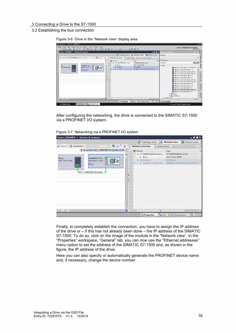
Figure 3-6 Drive in the “Network view” display area
After configuring the networking, the drive is connected to the SIMATIC S7-1500via a PROFINET I/O system.
Figure 3-7 Networking via a PROFINET I/O system
Finally, to completely establish the connection, you have to assign the IP addressof the drive or – if this has not already been done – the IP address of the SIMATICS7-1500. To do so, click on the image of the module in the “Network view”. In the“Properties” workspace, “General” tab, you can now use the “Ethernet addresses”menu option to set the address of the SIMATIC S7-1500 and, as shown in thefigure, the IP address of the drive.Here you can also specify or automatically generate the PROFINET device nameand, if necessary, change the device number.

3 Connecting a Drive to the S7-15003.2 Establishing the bus connection
Integrating a Drive via the GSD FileEntry-ID: 73257075, V1.2, 12/2014 17
Figure 3-8 Assigning the IP address on the drive
NOTICE For this configuration of the drive, please note that the settings in the TIAPortal are made completely independently of the drive and that they must,of course, match the settings that already exist in the drive or that therespective settings also have to be made using the commissioningsoftware of the drive.
4 Establishing the Communication Connection4.1 Telegram selection
Integrating a Drive via the GSD FileEntry-ID: 73257075, V1.2, 12/2014 18
4 Establishing the CommunicationConnection
4.1 Telegram selectionData exchange between the SIMATIC S7-1500 and the drive takes place using so-called telegrams via which the data to be exchanged is defined according to thePROFIdrive standard.
4.1.1 Drive telegrams that can be used with the SIMATIC S7-1500
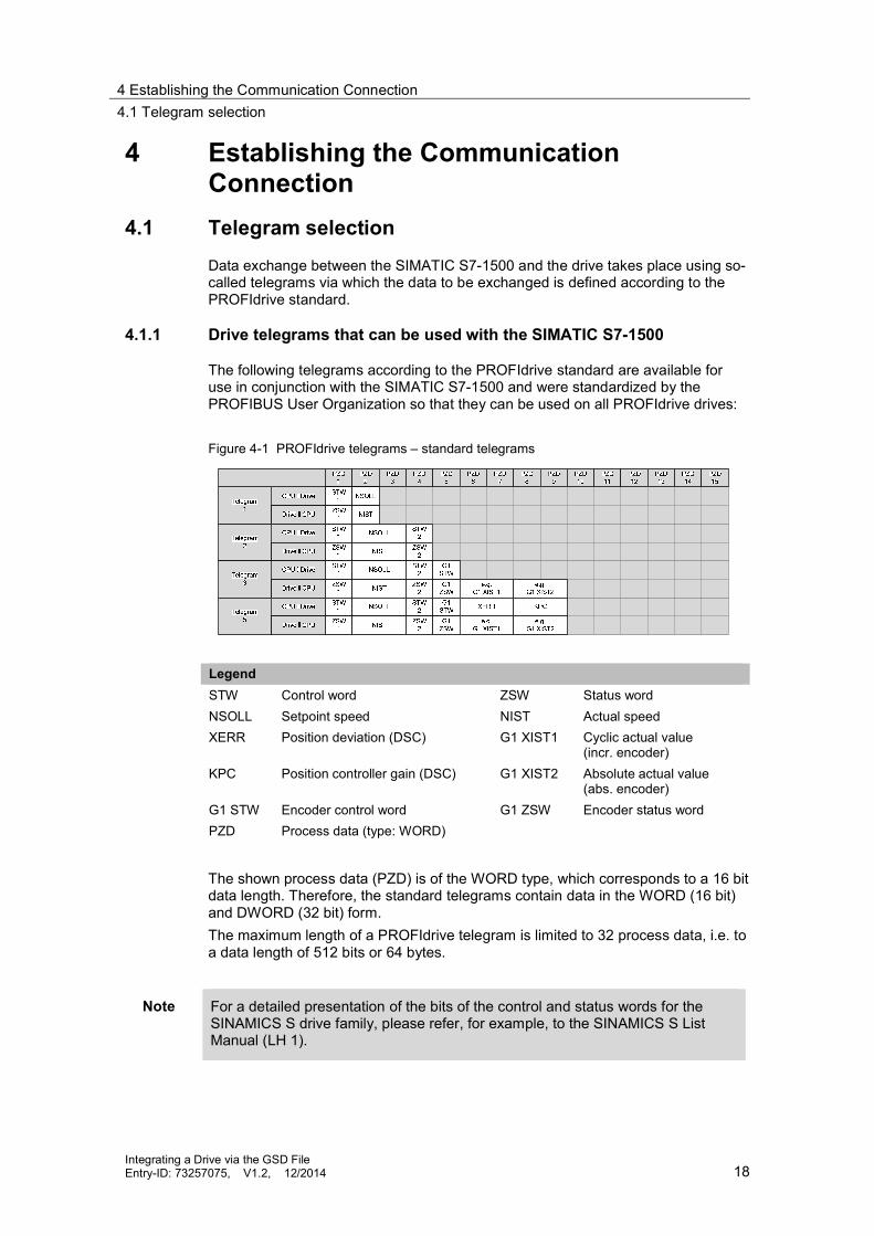
The following telegrams according to the PROFIdrive standard are available foruse in conjunction with the SIMATIC S7-1500 and were standardized by thePROFIBUS User Organization so that they can be used on all PROFIdrive drives:
Figure 4-1 PROFIdrive telegrams – standard telegrams
LegendSTW Control word ZSW Status wordNSOLL Setpoint speed NIST Actual speedXERR Position deviation (DSC) G1 XIST1 Cyclic actual value
(incr. encoder)KPC Position controller gain (DSC) G1 XIST2 Absolute actual value
(abs. encoder)G1 STW Encoder control word G1 ZSW Encoder status wordPZD Process data (type: WORD)
The shown process data (PZD) is of the WORD type, which corresponds to a 16 bitdata length. Therefore, the standard telegrams contain data in the WORD (16 bit)and DWORD (32 bit) form.The maximum length of a PROFIdrive telegram is limited to 32 process data, i.e. toa data length of 512 bits or 64 bytes.
Note For a detailed presentation of the bits of the control and status words for theSINAMICS S drive family, please refer, for example, to the SINAMICS S ListManual (LH 1).

4 Establishing the Communication Connection4.1 Telegram selection
Integrating a Drive via the GSD FileEntry-ID: 73257075, V1.2, 12/2014 19
4.1.2 Selection aid for the drive telegrams
To select the suitable telegram for data transfer between the SIMATIC S7-1500and the drive, it is necessary to take a closer look at the main criteria of thetelegrams: Accuracy of the transferred setpoint or actual value
Is the 16 bit resolution transfer of the speed setpoint to the drive sufficient toachieve the desired function (speed setpoints or control response of theposition control graduated)?
Transfer of the encoder value connected to the driveDo you want to transfer the actual value of an encoder connected to the driveto the controller for position control in the SIMATIC S7-1500?
Use of the DSC (Dynamic Servo Control) drive functionDo you want to use the DSC (Dynamic Servo Control) drive function thatallows quick correction of faults directly in the drive to improve the controlproperties of the drive?
Select the appropriate telegram depending on the desired functionality. The tablebelow once again provides an overview of all the information.
Table 4-1 Selection aid for the drive telegrams
Criterion for telegram selection
Tele
gram
1
Tele
gram
2
Tele
gram
3
Tele
gram
5
Accuracy of the transferred setpoint and actual value16 bit data width (WORD) X32 bit data width (DWORD) X X XTransfer of the encoder value connected to the driveNo feedback of the encoder value (actual position) X XFeedback of the encoder value (actual position) X XUse of the DSC (Dynamic Servo Control) drive functionUse of DSC not possible X X XUse of DSC possible X
Note If the drive is connected to the SIMATIC S7-1500 via PROFINET I/O and youselect telegram 5, isochronous mode will be automatically activated for this axisdue to the GSDML file.
In this case, isochronous mode must be parameterized accordingly for this axisin the Totally Integrated Automation Portal (TIA Portal).
Note Currently, the use of control word 2 of telegrams 2, 3 and 5 is not supported inthe SIMATIC S7-1500.

4 Establishing the Communication Connection4.2 Connection via PROFIBUS DP
Integrating a Drive via the GSD FileEntry-ID: 73257075, V1.2, 12/2014 20
4.1.3 Supplementary telegrams of the SINAMICS S drive family
In addition to the drive telegrams, the SINAMICS S drive family provides Siemens-specific supplementary telegrams for data exchange between the SIMATIC S7-1500 and the Control Unit or infeed (Active Infeed – Active Line Module) of thedrive.The following supplementary telegrams can be used for data exchange:
Figure 4-2 Supplementary telegrams of the SINAMICS S drive family
LegendE_STW Infeed control word E_ZSW Infeed status wordA Digital Digital outputs of the CU E Digital Digital inputs of the CUMT STW Measuring probe control word MT ZSW Measuring probe status wordMT1 Measuring probe 1 MT6 Measuring probe 6ZS_F Measuring time, falling edge ZS_S Measuring time, rising edge
The supplementary telegrams of the SINAMICS S drive family can only beaccessed or evaluated via the SIMATIC S7-1500 user program. It is not possible touse these telegrams via technology objects of the motion control functions of theSIMATIC S7-1500.These telegrams allow you to easily implement an influence on the Control Unit orthe drive infeed and the use of the digital inputs and outputs of the Control Unit inthe SIMATIC S7-1500, for example for limit switch signals.
Note Switch-on of an Active Infeed or Active Line Module (ALM) for use of the driveaxes must be performed separately, for example using telegram 370 listed here.Automatic switch-on of the infeed via the “MC_Power” technology function is notperformed.
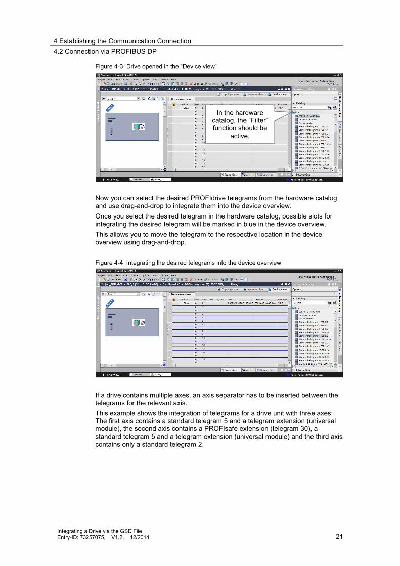
4.2 Connection via PROFIBUS DPIn the Totally Integrated Automation Portal (TIA Portal), double-click on the desireddrive to go to the “Device view”. If the “Filter” function is activated in the hardwarecatalog, the “Device view” will automatically display the PROFIdrive telegramsavailable for this drive.
4 Establishing the Communication Connection4.2 Connection via PROFIBUS DP
Integrating a Drive via the GSD FileEntry-ID: 73257075, V1.2, 12/2014 21
Figure 4-3 Drive opened in the “Device view”
Now you can select the desired PROFIdrive telegrams from the hardware catalogand use drag-and-drop to integrate them into the device overview.Once you select the desired telegram in the hardware catalog, possible slots forintegrating the desired telegram will be marked in blue in the device overview.This allows you to move the telegram to the respective location in the deviceoverview using drag-and-drop.
Figure 4-4 Integrating the desired telegrams into the device overview
If a drive contains multiple axes, an axis separator has to be inserted between thetelegrams for the relevant axis.This example shows the integration of telegrams for a drive unit with three axes:The first axis contains a standard telegram 5 and a telegram extension (universalmodule), the second axis contains a PROFIsafe extension (telegram 30), astandard telegram 5 and a telegram extension (universal module) and the third axiscontains only a standard telegram 2.
In the hardwarecatalog, the “Filter”function should be
active.

4 Establishing the Communication Connection4.2 Connection via PROFIBUS DP
Integrating a Drive via the GSD FileEntry-ID: 73257075, V1.2, 12/2014 22
Figure 4-5 Sample telegram selection for a drive unit with 3 axes
NOTICE Do not forget to separate the data areas (telegram areas) of two axes by anaxis separator.
If the axis separator is not used, an unexpected response of an axis mayoccur, for example for data areas that have not been completely defined, assub-areas of telegrams could possibly be assigned to the wrong axis.
An axis separator must not be defined in front of the first telegram.
A telegram extension is implemented with the aid of the universal module. For thismodule, you can define an input range and/or an output range and a specific datalength that corresponds to the desired telegram length.
Figure 4-6 Type definition of the universal module
Axis 1
Axis 3Axis 2
Axis separator

4 Establishing the Communication Connection4.3 Connection via PROFINET I/O
Integrating a Drive via the GSD FileEntry-ID: 73257075, V1.2, 12/2014 23
Figure 4-7 Address definition for the universal module of the “input/output” type
Note In the hardware configuration (device overview), the names “Input addresses”and “Output addresses” refer to the perspective of the SIMATIC S7-1500:
Output or O address:Data area for communication from the SIMATIC S7-1500 to the drive.
Input or I address:Data area for communication from the drive to the SIMATIC S71500.
NOTICE For this configuration of the drive, please note that the settings in the TIAPortal are made completely independently of the drive and that they must,of course, match the settings that already exist in the drive or that therespective settings also have to be made using the commissioningsoftware of the drive.
4.3 Connection via PROFINET I/O
In the Totally Integrated Automation Portal (TIA Portal), double-click on the desireddrive to go to the “Device view”. If the “Filter” function is activated in the hardware
Type selection
Start address
Telegram length
Start address
Telegram length

4 Establishing the Communication Connection4.3 Connection via PROFINET I/O
Integrating a Drive via the GSD FileEntry-ID: 73257075, V1.2, 12/2014 24
catalog, the “Device view” will automatically only display the modules (drive objects“DO”) available for this drive.
Figure 4-8 Drive opened in the “Device view”
Before you can insert the desired PROFIdrive telegrams into the device overview,you have to create a drive object (DO) for each axis of the drive. For the headmodule SINAMICS S120 CU320 2PN, used in this example, the following DOs areavailable:
without cyclic process data interchange:DO without PZDAxes: DO Servo, DO HLA, DO Vector, …Active Line Modules: DO infeedExternal encoders: DO ENCODERTerminal module: DO Terminal Board/ModuleModule for encoder simulation: DO TM41
Control Unit: DO Control Unit
Drag-and-drop the Drive Object (DO) you want to address in the selected drivefrom the hardware catalog into one of the rows marked in blue.
In the hardwarecatalog, the “Filter”function should be
active.

4 Establishing the Communication Connection4.3 Connection via PROFINET I/O
Integrating a Drive via the GSD FileEntry-ID: 73257075, V1.2, 12/2014 25
Figure 4-9 Creating the axes of the drive unit as a drive object (DO)
NOTE Please note that, without filter (= “Filter” not checked), the respective driveobjects (DOs) may be listed multiple times in the hardware catalog. To determinethe correct drive object (DO) with switched-off filter, successively click on alldrive objects (DOs) listed in the hardware catalog. As soon as the rows forinserting the drive object (DO) are marked in blue, you have determined thecorrect object and can apply it to the selected rows in the device overview usingdrag-and-drop.
Once you have created the axes of the drive unit as drive objects (DOs), you candefine the desired submodules (telegrams) below the DOs in the hardware catalog.To do so, select the required telegrams and use drag-and-drop to move them tothe device overview.
Figure 4-10 Integrating the desired telegrams into the device overview

4 Establishing the Communication Connection4.3 Connection via PROFINET I/O
Integrating a Drive via the GSD FileEntry-ID: 73257075, V1.2, 12/2014 26
This example shows the integration of telegrams for a drive unit with three axes:The first axis contains a standard telegram 5 and a telegram extension(Supplementary data, PZD2/4), the second axis contains a PROFIsafe extension(telegram 30), a standard telegram 5 and a telegram extension (Supplementarydata, PZD2/4) and the third axis contains only a standard telegram 2.
Figure 4-11 Sample telegram selection for a drive unit with 3 axes
The telegram extension is implemented with the aid of the “Supplementary data,PZD x/y” telegram. The data to be exchanged cannot be freely configured, it isdefined by selecting the telegram:
Supplementary data, PZD-2/22 words from the drive to the SIMATIC S7-15002 words from the SIMATIC S7-1500 to the drive
Supplementary data, PZD-2/42 words from the drive to the SIMATIC S7-15004 words from the SIMATIC S7-1500 to the drive
Supplementary data, PZD-2/62 words from the drive to the SIMATIC S7-15006 words from the SIMATIC S7-1500 to the drive
Note In the hardware configuration (device overview), the names “Input addresses”and “Output addresses” refer to the perspective of the SIMATIC S7-1500:
Output or O address:Data area for communication from the SIMATIC S7-1500 to the drive.Input or I address:Data area for communication from the drive to the SIMATIC S7-1500.
NOTICE For this configuration of the drive, please note that the settings in the TIAPortal are made completely independently of the drive and that they must,of course, match the settings that already exist in the drive or that therespective settings also have to be made using the commissioningsoftware of the drive.
Axis 1
Axis 2
Axis 3

5 Setting Isochronous Mode5.1 PROFIBUS DP
Integrating a Drive via the GSD FileEntry-ID: 73257075, V1.2, 12/2014 27
5 Setting Isochronous ModeIf the axes connected to the SIMATIC S7-1500 are to be used as positioning axesvia the position control of the technology object of the SIMATIC S7-1500 or if theDSC (Dynamic Servo Control) function, which moves the position control to thedrive for quicker compensation of disturbances, is to be used to increase axisaccuracy, the drive must be connected to the automation system via anisochronous bus system.
Note If the drive is connected to the SIMATIC S7-1500 via PROFINET I/O and youselect telegram 5, isochronous mode will be automatically activated for this axisdue to the GSDML file.
In this case, isochronous mode must be parameterized accordingly for this axisin the Totally Integrated Automation Portal (TIA Portal).
The next chapters provide you with information on setting up an isochronous bussystem for PROFIBUS DP and PROFINET I/O.
5.1 PROFIBUS DP
5.1.1 Basics and definition
Constant bus cycle timeConstant bus cycle time ensures that the time interval for bus cycles has exactlythe same length. “Bus cycles of the same length” mean that the PROFIBUS DPmaster always starts the DP bus cycle after the same time interval. Therefore, theconnected slaves too receive their data from the master at time intervals of theexact same length. This is also referred to as “bus cycle clocking”.Constant bus cycle time is the prerequisite for isochronous mode.
Isochronous modeThe “Isochronous mode” system property allows acquisition of measured valuesand process data in a fixed system cycle. Within the same system cycle, the signalis processed until it is available at the output terminal. Therefore, isochronousmode contributes to high control system quality, which results in greatermanufacturing accuracy. Isochronous mode drastically reduces possiblefluctuations in process reaction times. This processing stable in terms of time canbe used for higher machine cycles.Basically, isochronous mode is the choice where measured values need to beacquired synchronously, motions need to be coordinated and process reactionsneed to be defined and take place simultaneously.
5.1.2 Settings in the TIA Portal
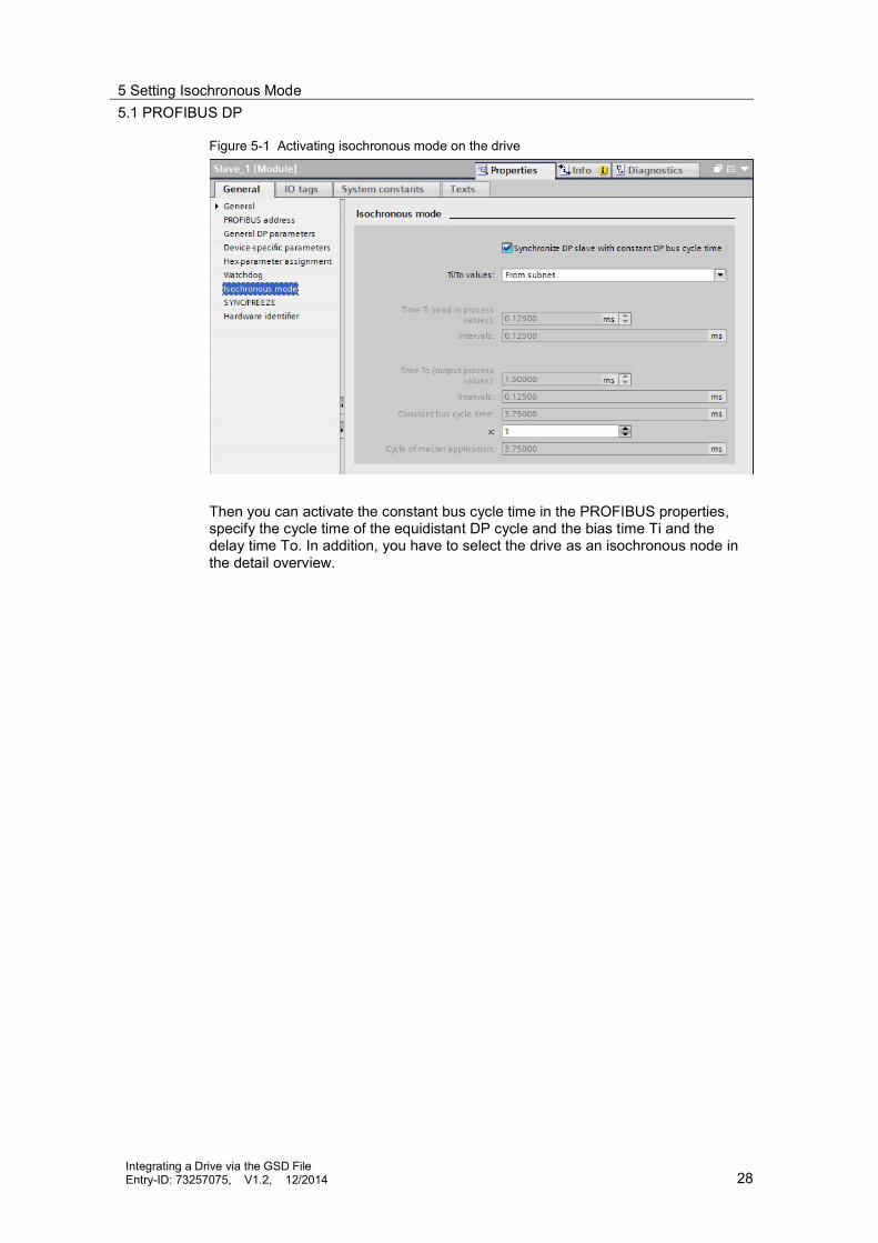
To activate isochronous operation, first activate isochronous mode in the drive’sproperties.
5 Setting Isochronous Mode5.1 PROFIBUS DP
Integrating a Drive via the GSD FileEntry-ID: 73257075, V1.2, 12/2014 28
Figure 5-1 Activating isochronous mode on the drive
Then you can activate the constant bus cycle time in the PROFIBUS properties,specify the cycle time of the equidistant DP cycle and the bias time Ti and thedelay time To. In addition, you have to select the drive as an isochronous node inthe detail overview.

5 Setting Isochronous Mode5.2 PROFINET I/O
Integrating a Drive via the GSD FileEntry-ID: 73257075, V1.2, 12/2014 29
Figure 5-2 Activating constant bus cycle time on PROFIBUS
5.2 PROFINET I/O
5.2.1 Basics and definition
IRT Ethernet – Isochronous Real-Time EthernetIRT is a transmission mode where PROFINET devices are synchronized withextreme accuracy.A sync master provides the clock, sync slaves synchronize with this clock. Both anIO controller and an IO device can act as a sync master.Sync master and sync slaves are always nodes of a sync domain. Within the syncdomain, bandwidth is reserved for IRT communication. Real-time and non-real-timecommunication (TCP/IP communication) is possible outside the reservedbandwidth.
Sync domainA sync domain is necessary to synchronize PROFINET IO devices. The syncdomain ensures that all nodes of this domain can communicate in isochronousmode.The prerequisite for IRT communication is a synchronization cycle for allPROFINET devices in a sync domain for distributing a common time base. This

5 Setting Isochronous Mode5.2 PROFINET I/O
Integrating a Drive via the GSD FileEntry-ID: 73257075, V1.2, 12/2014 30
basic synchronization allows a synchronism of the transmission cycle of thePROFINET devices within a sync domain. The sync master (generally an IOcontroller) generates the common synchronization clock and specifies the timebase with which all other sync slaves (e.g., IO devices) synchronize.If the sync master fails, the communication of the IRT devices falls back to RTquality.
Setting up PROFINET with IRTWhen setting up and operating a PROFINET IO system in IRT mode, please followthe rules below. The aim of these rules is to ensure optimum operation of yourPROFINET IO system. When using IRT, you must configure the topology. This ensures the exact
calculation of update time, bandwidth and other parameters. If you want to use multiple sync domains, configure a sync domain boundary
for the port connected to a PROFINET device of another sync domain. In a sync domain, you can only configure one sync master at a time. A PROFINET IO system may only belong to a single sync domain. If you configure PROFINET devices in a sync domain and want to synchronize
them with IRT, the relevant PROFINET devices must support IRTcommunication.
Where possible, use the same PROFINET device as the PROFINET IOcontroller and sync master.
If only some of the PROFINET devices of a PROFINET IO system aresynchronized, place PROFINET devices that are not participating in IRTcommunication outside the sync domain.
Isochronous modeThe “Isochronous mode” system property allows acquisition of measured valuesand process data in a fixed system cycle. Within the same system cycle, the signalis processed until it is available at the output terminal. Therefore, isochronousmode contributes to high control system quality, which results in greatermanufacturing accuracy. Isochronous mode drastically reduces possiblefluctuations in process reaction times. This processing stable in terms of time canbe used for higher machine cycles.Basically, isochronous mode is the choice where measured values need to beacquired synchronously, motions need to be coordinated and process reactionsneed to be defined and take place simultaneously.
Time sequence of isochronous processingThe following section explains the basic time sequence of all components involvedin the synchronization from reading in the input data to outputting the output data: Reading in the input data in isochronous mode Transporting the input data to the IO controller (CPU) via the PROFINET
subnet Processing the data in the isochronous application of the CPU Transporting the output data to the outputting IO device via the PROFINET
subnet Outputting the output data in isochronous mode

5 Setting Isochronous Mode5.2 PROFINET I/O
Integrating a Drive via the GSD FileEntry-ID: 73257075, V1.2, 12/2014 31
Bias time TiTo ensure that a consistent status of the inputs can be transferred to the IOcontroller at the start time of a new system cycle, the read action must be movedup by the time Ti. For a specific input module, the time Ti includes at least thesignal conditioning and conversion time on the electronic modules and the time fortransfer to the interface module on the IO device backplane bus.In a plant, the values are read in simultaneously because the bias time Ti of allinput modules read in isochronous mode is set to the same value and this value isgreater than or equal to the longest minimum bias time Ti of all isochronous inputmodules. With the default setting, STEP 7 ensures that a common bias time Ti isset that is as short as possible.
Delay time ToTo ensure that a consistent status of the outputs can be transferred to the processat the start time of a new system cycle, the output at the terminal does not takeplace before the time To after the clock beat. For a specific output module, the timeTo includes at least the transfer time from the IO controller to the IO device (viaPROFINET IO) and in the IO device, the transfer of the outputs from the interfacemodule to the electronic module (backplane bus) with the time for digital-to-analogconversion possibly included in this module.In the plant, these values are written simultaneously because the delay time To ofall isochronous output modules is set to the same value. This value must begreater than or equal to the longest minimum delay time To of all isochronousoutput modules. STEP 7 automatically calculates a common delay time To that isas short as possible.
Isochronous mode – instructions for use for components and interfacesWhen establishing isochronous communication via PROFINET, please note thefollowing: Isochronous mode is only possible with the interfaces integrated in the CPU.
For the SIMATIC S7-1500 with two PROFINET interfaces, only interface X1can be configured for PROFINET IO and isochronous mode. Isochronousmode is not possible with CPs.
Full isochronous mode from “terminal” to “terminal” is only possible if allcomponents involved in the chain support the “Isochronous mode” systemproperty. When selecting in the catalog, look for the “Isochronous mode” or“Isochronous processing” item in the information box of the module.
If you are operating an IO device in isochronous mode (i.e. you have assignedit, for example, the sync slave role), the IO device must include at least onemodule or submodule operated in isochronous mode.
Note When using PROFINET, the configured PROFINET name of the drive in theTotally Integrated Automation Portal (TIA Portal) must match the configuredname in the commissioning software of the drive, e.g. SINAMICSMICROMASTER STARTER.Please note that the name is case sensitive.
If the PROFINET name in the Totally Integrated Automation Portal (TIA Portal)differs from the one in the drive, it may not be possible to establish a connectionbetween the SIMATIC S7-1500 and the drive.

5 Setting Isochronous Mode5.2 PROFINET I/O
Integrating a Drive via the GSD FileEntry-ID: 73257075, V1.2, 12/2014 32
5.2.2 Settings in the TIA Portal
To activate isochronous mode, both the parameters for isochronous mode and thesync domain must be configured in the TIA Portal.
Isochronous modeIn the device overview of the drive on the telegram of the desired axis, selectProperties > I/O addresses and activate the “Isochronous mode” function for theinput and output addresses of the axis.At this point, it is not yet necessary to assign the organization block for isochronousmode. This is done automatically when assigning the axis to a technology object inthe SIMATIC S7-1500.
Figure 5-3 Activating isochronous mode
Note If the drive is connected to the SIMATIC S7-1500 via PROFINET I/O and youselect telegram 5, isochronous mode will be automatically activated for this axisdue to the GSDML file.
In this case, isochronous mode must be parameterized accordingly for this axisin the Totally Integrated Automation Portal (TIA Portal).
On the Control Unit of the drive, select Properties > Isochronous mode and activatethe “Isochronous mode” function and set the values for bias time Ti and delay timeTo.When using a drive of the SINAMICS S drive family, select the manual setting ofthe Ti and To times and set the values of these times to a multiple of 0.375 ms.

5 Setting Isochronous Mode5.2 PROFINET I/O
Integrating a Drive via the GSD FileEntry-ID: 73257075, V1.2, 12/2014 33
Figure 5-4 Activating isochronous mode
NOTICE In order to use isochronous mode in conjunction with the SINAMICS Sdrive family, the times Ti (read in process values) and To (output processvalues) must be manually set to a multiple of 0.375 ms.
Sync domainTo go to the sync domain settings, select Properties > Real time settings >Synchronization of the Control Unit of the drive. The “Domain settings” button takesyou directly to the properties of the PROFINET line.

5 Setting Isochronous Mode5.2 PROFINET I/O
Integrating a Drive via the GSD FileEntry-ID: 73257075, V1.2, 12/2014 34
Figure 5-5 Real time settings – setting the sync domain
Here you can assign the sync domain nodes the respective roles: SIMATIC S7-1500 (via PROFINET) = “sync master” SINAMICS S120 drive system = “sync slave” with RT class = “IRT”
Figure 5-6 Sync domain – assigning the synchronization role
Here you cancheck the set bus
cycle time.
This button takesyou to the sync
domain settings.
Here you canassign the
SIMATIC S7-1500the role of the“sync master”.Here you can select the “IRT”
RT class for the drive.

5 Setting Isochronous Mode5.2 PROFINET I/O
Integrating a Drive via the GSD FileEntry-ID: 73257075, V1.2, 12/2014 35
Finally, you can check the settings you have made via the PROFINET line in the“Overview isochronous mode”. Once a technology object has been created, theorganization block of the technology object is automatically entered in the detailoverview in “Application with isochronous mode”. The shown Ti and To values ofthe organization block form the time base for isochronous mode of the PROFIBUSline. The values for the bias time Ti and the delay time To actually set on the drivecan be read in the list of IO devices/modules.
Figure 5-7 Overview isochronous mode
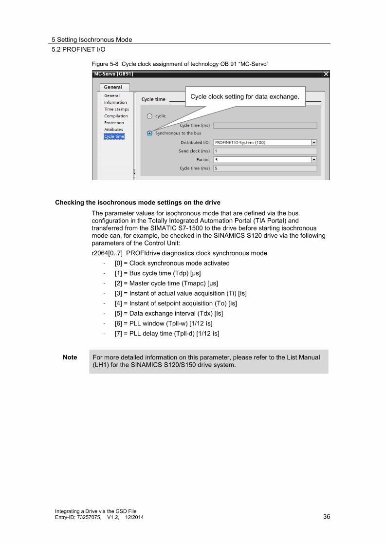
Additional setting on the technology objectIf a technology object is created after setting isochronous mode – as referred to inthis documentation –, technology OB 91 “MC_Servo” will be created. In theproperties of this organization block, the data exchange synchronization must beset in “Cycle time”. For isochronous data exchange via PROFINET I/O, select the“Synchronous to the bus” setting.
5 Setting Isochronous Mode5.2 PROFINET I/O
Integrating a Drive via the GSD FileEntry-ID: 73257075, V1.2, 12/2014 36
Figure 5-8 Cycle clock assignment of technology OB 91 “MC-Servo”
Checking the isochronous mode settings on the driveThe parameter values for isochronous mode that are defined via the busconfiguration in the Totally Integrated Automation Portal (TIA Portal) andtransferred from the SIMATIC S7-1500 to the drive before starting isochronousmode can, for example, be checked in the SINAMICS S120 drive via the followingparameters of the Control Unit:r2064[0..7] PROFIdrive diagnostics clock synchronous mode
– [0] = Clock synchronous mode activated– [1] = Bus cycle time (Tdp) [ s]– [2] = Master cycle time (Tmapc) [ s]– [3] = Instant of actual value acquisition (Ti) [ìs]– [4] = Instant of setpoint acquisition (To) [ìs]– [5] = Data exchange interval (Tdx) [ìs]– [6] = PLL window (Tpll-w) [1/12 ìs]– [7] = PLL delay time (Tpll-d) [1/12 ìs]
Note For more detailed information on this parameter, please refer to the List Manual(LH1) for the SINAMICS S120/S150 drive system.
Cycle clock setting for data exchange.
6 Motion Control Functions of the S7-15006.1 Technology objects
Integrating a Drive via the GSD FileEntry-ID: 73257075, V1.2, 12/2014 37
6 Motion Control Functions of the S7-15006.1 Technology objects
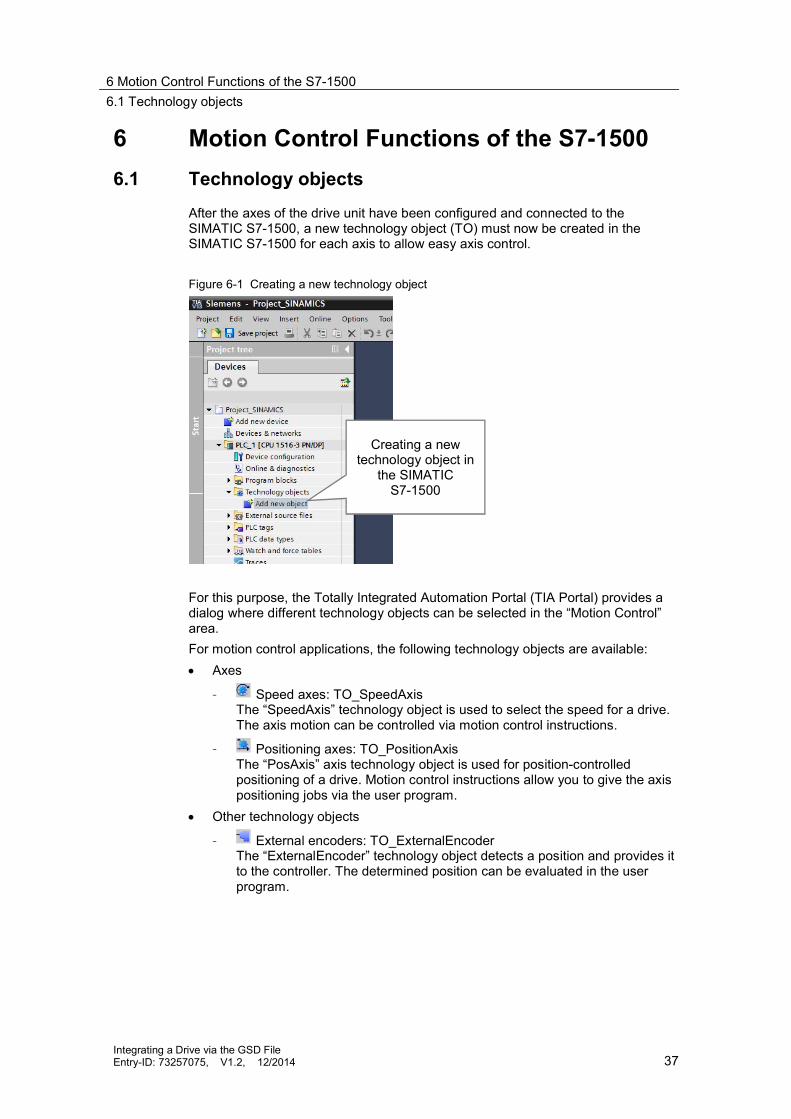
After the axes of the drive unit have been configured and connected to theSIMATIC S7-1500, a new technology object (TO) must now be created in theSIMATIC S7-1500 for each axis to allow easy axis control.
Figure 6-1 Creating a new technology object
For this purpose, the Totally Integrated Automation Portal (TIA Portal) provides adialog where different technology objects can be selected in the “Motion Control”area.For motion control applications, the following technology objects are available: Axes
– Speed axes: TO_SpeedAxisThe “SpeedAxis” technology object is used to select the speed for a drive.The axis motion can be controlled via motion control instructions.
– Positioning axes: TO_PositionAxisThe “PosAxis” axis technology object is used for position-controlledpositioning of a drive. Motion control instructions allow you to give the axispositioning jobs via the user program.
Other technology objects
– External encoders: TO_ExternalEncoderThe “ExternalEncoder” technology object detects a position and provides itto the controller. The determined position can be evaluated in the userprogram.
Creating a newtechnology object in
the SIMATICS7-1500

6 Motion Control Functions of the S7-15006.2 Selecting the drive on the technology object
Integrating a Drive via the GSD FileEntry-ID: 73257075, V1.2, 12/2014 38
Figure 6-2 Creating a technology object for motion control in the SIMATIC S7-1500
6.2 Selecting the drive on the technology objectAfter adding the desired technology object, the appropriate drive unit axis must beconnected to the technology object.In the technology object, select Hardware interface > Drive. In the “Drive” selectionbox, select the appropriate drive object (DO) for PROFINET or the appropriatetelegram of the desired axis for PROFIBUS.
Figure 6-3 Assigning the axis to the technology object

6 Motion Control Functions of the S7-15006.2 Selecting the drive on the technology object
Integrating a Drive via the GSD FileEntry-ID: 73257075, V1.2, 12/2014 39
Note If the desired drive object (DO) for PROFINET or the desired telegram of the axisfor PROFIBUS has been configured but is not displayed in the selection dialog,activate the “Show all modules” function in the selection dialog and try again.
Occasionally, older GSD files do not contain PROFIdrive telegrams but onlyinput/output ranges of the respective size. In these cases, select the desireddrive object by explicitly selecting the associated input and output data. Chapter9.1 describes an example with a SIMODRIVE double axis drive.
Now the desired axis is connected to the technology object of the SIMATIC S7-1500.
Figure 6-4 Technology object – Hardware interface > Data exchange
Note If the data is exchanged with the selected axis via PROFIdrive telegram 5, theDSC (Dynamic Servo Control) function to move the position control to the drive isautomatically enabled when creating the Positioning Axis technology object.
If you do not want to use DSC (Dynamic Servo Control), explicitly change thisfunction in the technology object in Extended Parameters > Control loop from“Position control and speed control in drive (DSC enabled)” to “Position controland speed control in the PLC”. Axis position control is then only performed by thetechnology object.

6 Motion Control Functions of the S7-15006.3 Controlling the axis from the user program
Integrating a Drive via the GSD FileEntry-ID: 73257075, V1.2, 12/2014 40
6.3 Controlling the axis from the user programTo control the axes created as technology objects, the SIMATIC S7-1500 providesmultiple technology functions that allow the user to influence the technologyobjects quickly and easily.To influence the technology objects from the user program, the following functionsare available:
Table 6-1 Technology functions
Technology function Can be used for thefollowing
technology objects
Description
MC_Power Positioning axisSpeed axisExternal encoder
“MC_Power” is used to enable or disablea technology object.Note:When using a drive of the SINAMICS Sfamily with Active Infeed or Active LineModule (ALM), the infeed must beswitched on separately. Automaticswitch-on of the infeed via “MC_Power”is not performed.
MC_Reset Positioning axisSpeed axisExternal encoder
“MC_Reset” is used to acknowledge alltechnology alarms that can beacknowledged in the user program. Theacknowledgement also resets the “Error”and “Warning” bits in the technologydata block.The “Restart” input of “MC_Reset” isused to start the reinitialization oftechnology objects. When restarting thetechnology object, new configurationdata is applied to the technology datablock.
MC_Home Positioning axisExternal encoder
“MC_Home” is used to create thereference between the position on thetechnology object and the mechanicalposition of the associated axis. Theactual position value on the technologyobject is assigned to a reference mark.This reference mark represents a knownmechanical position.Homing is performed according to themode selected on the “Mode” parameterand the configuration in “Technologyobject > Configuration > Extendedparameters > Homing”.
MC_Halt Positioning axisSpeed axis
“MC_Halt” is used to decelerate an axisto a standstill.The “Jerk” and “Deceleration”parameters are used to define thedynamic response for deceleration.
6 Motion Control Functions of the S7-15006.3 Controlling the axis from the user program
Integrating a Drive via the GSD FileEntry-ID: 73257075, V1.2, 12/2014 41
Technology function Can be used for thefollowing
technology objects
Description
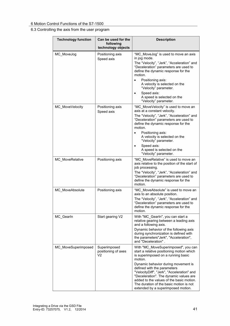
MC_MoveJog Positioning axisSpeed axis
“MC_MoveJog” is used to move an axisin jog mode.The “Velocity”, “Jerk”, “Acceleration” and“Deceleration” parameters are used todefine the dynamic response for themotion. Positioning axis:
A velocity is selected on the“Velocity” parameter.
Speed axis:A speed is selected on the“Velocity” parameter.
MC_MoveVelocity Positioning axisSpeed axis
“MC_MoveVelocity” is used to move anaxis at a constant velocity.The “Velocity”, “Jerk”, “Acceleration” and“Deceleration” parameters are used todefine the dynamic response for themotion. Positioning axis:
A velocity is selected on the“Velocity” parameter.
Speed axis:A speed is selected on the“Velocity” parameter.
MC_MoveRelative Positioning axis “MC_MoveRelative” is used to move anaxis relative to the position of the start ofjob processing.The “Velocity”, “Jerk”, “Acceleration” and“Deceleration” parameters are used todefine the dynamic response for themotion.
MC_MoveAbsolute Positioning axis “MC_MoveAbsolute” is used to move anaxis to an absolute position.The “Velocity”, “Jerk”, “Acceleration” and“Deceleration” parameters are used todefine the dynamic response for themotion.
MC_GearIn Start gearing V2 With "MC_GearIn", you can start arelative gearing between a leading axisand a following axis.Dynamic behavior of the following axisduring synchronization is defined withthe parameters"Jerk", "Acceleration",and "Deceleration" .
MC_MoveSuperimposed Superimposedpositioning of axesV2
With "MC_MoveSuperimposed", you canstart a relative positioning motion whichis superimposed on a running basicmotion.Dynamic behavior during movement isdefined with the parameters"VelocityDiff", "Jerk", "Acceleration" and"Deceleration". The dynamic values areadded to the values of the basic motion.The duration of the basic motion is notextended by a superimposed motion.

6 Motion Control Functions of the S7-15006.3 Controlling the axis from the user program
Integrating a Drive via the GSD FileEntry-ID: 73257075, V1.2, 12/2014 42
Note For detailed information on the use of the technology functions, please refer tothe documentation for the motion control functions of the SIMATIC S7-1500 orthe Totally Integrated Automation Portal (TIA Portal) documentation.

7 STARTER Commissioning Software7.1 Working with drives
Integrating a Drive via the GSD FileEntry-ID: 73257075, V1.2, 12/2014 43
7 STARTER Commissioning Software7.1 Working with drives
Unlike the configuration of the SIMATIC S7-1500 in the Totally IntegratedAutomation Portal (TIA Portal) where the controller configuration is defined offlinevia “Devices & Networks” and then loaded to the controller, drives of theSINAMICS G and SINAMICS S families are generally configured online.
Figure 7-1 Searching for a drive unit online using “Accessible nodes”
The drive system is set up ready for operation and the current drive configuration isthen loaded to the SINAMICS MICROMASTER STARTER commissioning softwarevia an online connection. This ensures that drives with Drive-CLiQ components canbe commissioned very quickly and easily.
Figure 7-2 Automatically configuring the drive unit
7 STARTER Commissioning Software7.2 Creating a drive unit
Integrating a Drive via the GSD FileEntry-ID: 73257075, V1.2, 12/2014 44
Note For more information on the use of the SINAMICS MICROMASTER STARTERcommissioning software, please refer to the appropriate manual or the help filefor SINAMICS MICROMASTER STARTER.
If not all components of the drive system feature Drive-CLiQ technology or if drivecomponents were used that do not support automatic commissioning, the drivesystem can, of course, also be commissioned manually via offline configuration.The next chapter briefly describes this procedure before it provides greater detailson adapting the message frame configuration.
7.2 Creating a drive unit
The best way to commission a drive of the SINAMICS family is to create a newdrive project and add a new single drive to this project.
7.2.1 PROFIBUS DP
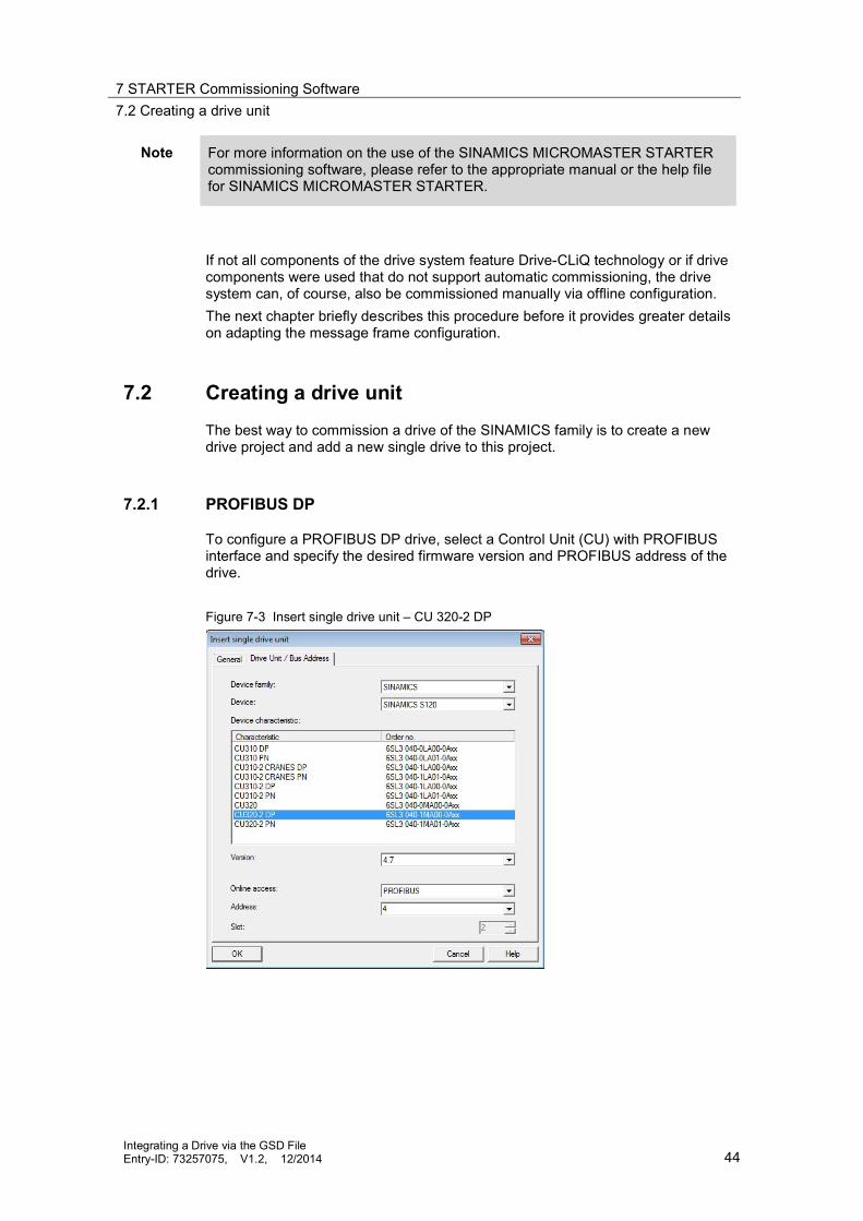
To configure a PROFIBUS DP drive, select a Control Unit (CU) with PROFIBUSinterface and specify the desired firmware version and PROFIBUS address of thedrive.
Figure 7-3 Insert single drive unit – CU 320-2 DP

7 STARTER Commissioning Software7.2 Creating a drive unit
Integrating a Drive via the GSD FileEntry-ID: 73257075, V1.2, 12/2014 45
7.2.2 PROFINET I/O
To configure a PROFINET I/O drive, select a Control Unit (CU) with PROFINETinterface and specify the desired firmware version and IP address of the drive.
Figure 7-4 Insert single drive unit – CU 320-2 PN

7 STARTER Commissioning Software7.3 Creating the drives
Integrating a Drive via the GSD FileEntry-ID: 73257075, V1.2, 12/2014 46
7.3 Creating the drives
Use the “Insert drive” menu option to add the appropriate drive axes of the drivesystem to the drive unit you have just created.
Figure 7-5 Insert drive
The wizard prompts you to enter the following drive parameters: Drive name Parameterization of the control structure Selection of the power unit Selection of the motor and a possibly existing motor holding brake Selection of the encoder system Basic configuration of the communication message frame of the drive

7 STARTER Commissioning Software7.3 Creating the drives
Integrating a Drive via the GSD FileEntry-ID: 73257075, V1.2, 12/2014 47
Figure 7-6 Creating and parameterizing a drive

7 STARTER Commissioning Software7.3 Creating the drives
Integrating a Drive via the GSD FileEntry-ID: 73257075, V1.2, 12/2014 48
7.3.1 Adapting the communication message frames
After you have created all required drives with a basic selection of communicationmessage frames, you can adapt the individual message frames so that theycorrespond to the settings in the Totally Integrated Automation Portal (TIA Portal).To do so, select the message frame to be adapted and select the “Adapt messageframe configuration” button.
Figure 7-7 Adapt message frame configuration
A message frame extension or supplementary data is inserted after the standardcommunication message frame. Adapt the quantity of the send and receive dataaccording to the settings in the Totally Integrated Automation Portal (TIA Portal).The PROFIsafe extension is inserted before the standard communication messageframe and does not require further editing.
Note Please note that a PROFIsafe extension cannot be added in the message frameconfiguration for the SINAMICS S120 with PROFIBUS DP interface orPROFINET I/O interface with firmware revision level V4.4.
In the overview, you can now check all message frame adaptations. They mustexactly correspond to the settings in the Totally Integrated Automation Portal (TIAPortal).

7 STARTER Commissioning Software7.3 Creating the drives
Integrating a Drive via the GSD FileEntry-ID: 73257075, V1.2, 12/2014 49
Figure 7-8 Adapted telegrams
Note Please note the send and receive data assignment. In the Totally IntegratedAutomation Portal (TIA Portal) and in the SINAMICS MICROMASTER STARTERcommissioning software, this data is always assigned from the perspective of thecontroller, for example the SIMATIC S7-1500.

8 Glossary
Integrating a Drive via the GSD FileEntry-ID: 73257075, V1.2, 12/2014 50
8 GlossaryThis chapter provides a brief explanation of special terms and abbreviations usedin this documentation.
Constant bus cycle time for PROFIBUS DPConstant bus cycle time ensures that the time interval for bus cycles has exactlythe same length. “Bus cycles of the same length” mean that the PROFIBUS DPmaster always starts the DP bus cycle after the same time interval. Therefore, theconnected slaves too receive their data from the master at time intervals of theexact same length. This is also referred to as “bus cycle clocking”.Constant bus cycle time is the prerequisite for isochronous mode.
Note For PROFIBUS DP, the maximum permissible cycle time for operatingisochronous drives is 8 ms.
This affects the maximum number of isochronous axes that can be operated onthe SIMATIC S7-1500. Please consider this when designing your automationconcept.
Drive object (DO) – generalA drive object (DO) is an independent, self-contained software functionality with itsown parameters and, if necessary, its own fault and alarm messages. Drive objects(DOs) can be provided by default (e.g., evaluation of inputs/outputs) or you canadd a single drive object (e.g., terminal board) or multiple drive objects (e.g., drivecontrol).Drive objects (DOs) processed by the Control Unit are set up via configurationparameters during first commissioning in STARTER. Various drive objects (DOs)can be created within a Control Unit. Drive objects (DOs) are configurable functionblocks that are used to execute specific drive functions. If you want to configure ordelete additional drive objects (DOs) after first commissioning, this must be doneusing configuration mode of the drive system. The parameters of a drive object(DO) cannot be accessed until the drive object has been configured and you havechanged from configuration mode to parameterization mode.
Drive object (DO) – drive controlA drive object (DO) for drive control has four slots on each port. The first slot ispermanently linked to the module access point and cannot be changed by the user.The second slot is reserved for the optional integration of a PROFIsafe telegram.The standard telegram of the drive for data exchange can be integrated into thethird slot. The fourth slot is reserved for the optional integration of a telegramextension.

8 Glossary
Integrating a Drive via the GSD FileEntry-ID: 73257075, V1.2, 12/2014 51
IRT Ethernet (Isochronous Real-Time Ethernet) for PROFINET I/OIRT is a transmission mode where PROFINET devices are synchronized withextreme accuracy. A sync master provides the clock, sync slaves synchronize withthis clock. Both an IO controller and an IO device can act as a sync master. Syncmaster and sync slaves are always nodes of a sync domain. Within the syncdomain, bandwidth is reserved for IRT communication. Real-time and non-real-timecommunication (TCP/IP communication) is possible outside the reservedbandwidth.The communication cycle for IRT Ethernet (Isochronous Real-Time Ethernet) issubdivided into the three time ranges shown in the figure below:
Figure 8-1 IRT Ethernet (Isochronous Real-Time Ethernet)
The individual communication time ranges have the following function: IRT data (synchronized communication)
Depending on the send clock, you can reserve this time range in specific steps.Only IRT data is transmitted during this time range.
RT data (real-time communication)The cyclic RT data is transmitted during this time range. RT data is prioritizedover “normal” TCP/IP data. TCP/IP data or Ethernet message frames can havea priority between 1 and 7. RT data has a priority of 6.
TCP/IP data (standard communication)Standard communication (TCP/IP, etc.) is transmitted in the remaining intervalof the communication cycle.
PROFINET with IRT is particularly suitable for: High performance and deterministics for large quantity frameworks in terms of
user data communication (productive data). High performance even with many nodes in line topology in terms of user data
communication (productive data). Parallel transmission of productive and TCP/IP data via one line, even with
high traffic volumes while ensuring productive data forwarding by reserving thetransmission bandwidth.
8 Glossary
Integrating a Drive via the GSD FileEntry-ID: 73257075, V1.2, 12/2014 52
NRT Ethernet (Non-Real-Time Ethernet) for PROFINET I/ONRT Ethernet (Non-Real-Time Ethernet) corresponds to the standardcommunication via Ethernet using TCP/IP, etc.
RT Ethernet (Real-Time Ethernet) for PROFINET I/ORT Ethernet (Real-Time Ethernet) corresponds to NRT Ethernet with prioritizedhandling of the data packets to be transmitted.
RT classes for PROFINET I/OPROFINET IO is a scalable real-time communication system based on Ethernettechnology. This scalable approach is expressed in different real-time classes: RT (Real-Time Ethernet):
Transmission of data in prioritized Ethernet message frames, notisochronously. The required bandwidth is in the free bandwidth for TCP/IPcommunication.
IRT (Isochronous Real-Time Ethernet):Isochronous transmission of data with high stability for time-critical applications(e.g., motion control). The required bandwidth is in the bandwidth reserved forcyclic data.
Depending on the device, not all real-time classes are supported.
Sync domain for PROFINET I/OA sync domain is a group of PROFINET devices that are synchronized to acommon clock. Exactly one device has the role of the sync master (clockgenerator), all other devices have the role of a sync slave. In most cases, the syncmaster is an IO controller or switch.Non-synchronized PROFINET devices are not part of a sync domain.
Synchronization clock for PROFINET I/OThe synchronization clock is the clock setting of the sync master for its role as thesync master (clock generator) for data exchange within a group of PROFINETdevices of a sync domain.
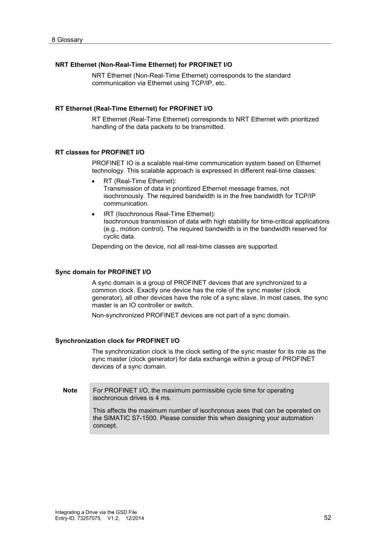
Note For PROFINET I/O, the maximum permissible cycle time for operatingisochronous drives is 4 ms.
This affects the maximum number of isochronous axes that can be operated onthe SIMATIC S7-1500. Please consider this when designing your automationconcept.

8 Glossary
Integrating a Drive via the GSD FileEntry-ID: 73257075, V1.2, 12/2014 53
Sync master for PROFINET I/OExactly one device in a sync domain has the role of the sync master and is theclock generator for clock synchronization of a group of PROFINET devices of async domain.
Sync slave for PROFINET I/OAll devices of a sync domain that do not have the role of the sync master are syncslaves. These devices synchronize with the clock specified by the sync master(clock generator) for data exchange within this sync domain.
Isochronous mode for PROFIBUS DPThe “Isochronous mode” system property allows acquisition of measured valuesand process data in a fixed system cycle. Within the same system cycle, the signalis processed until it is available at the output terminal. Therefore, isochronousmode contributes to high control system quality, which results in greatermanufacturing accuracy. Isochronous mode drastically reduces possiblefluctuations in process reaction times. This processing stable in terms of time canbe used for higher machine cycles.Basically, isochronous mode is the choice where measured values need to beacquired synchronously, motions need to be coordinated and process reactionsneed to be defined and take place simultaneously.The equidistant (isochronous) PROFIBUS forms the fundamental basis forsynchronized processing cycles. It provides a basic clock as a basis. The“Isochronous mode” system property connects an automation solution to theequidistant PROFIBUS.This means: Reading in the input data is synchronized with the DP cycle; all input data is
read in at the same time. The user program for processing the I/O data is synchronized with the DP
cycle using the isochronous interrupt OBs OB 61 to OB 64. Outputting output data is synchronized with the DP cycle; all output data
becomes effective at the same time. All input and output data is transferred consistently. This means that all the
data from the process image belongs together, both logically and with respectto timing.
Delay time To of isochronous mode for PROFIBUS DPTo ensure that a consistent status of the outputs can be transferred to the processat the start time of a new system cycle, the output at the terminal does not takeplace before the time To after the clock beat. For a specific output module, the timeTo includes at least the transfer time from the IO controller to the IO device (viaPROFINET IO) and in the IO device, the transfer of the outputs from the interfacemodule to the electronic module (backplane bus) with the time for digital-to-analogconversion possibly included in this module.In the plant, these values are written simultaneously because the delay time To ofall isochronous output modules is set to the same value. This value must begreater than or equal to the longest minimum delay time To of all isochronous

8 Glossary
Integrating a Drive via the GSD FileEntry-ID: 73257075, V1.2, 12/2014 54
output modules. STEP 7 automatically calculates a common delay time To that isas short as possible.
Bias time Ti of isochronous mode for PROFIBUS DPTo ensure that a consistent status of the inputs can be transferred to the IOcontroller at the start time of a new system cycle, the read action must be movedup by the time Ti. For a specific input module, the time Ti includes at least thesignal conditioning and conversion time on the electronic modules and the time fortransfer to the interface module on the IO device backplane bus.In the plant, the values are read in simultaneously because the bias time Ti of allinput modules read in isochronous mode is set to the same value and this value isgreater than or equal to the longest minimum bias time Ti of all isochronous inputmodules. With the default setting, STEP 7 ensures that a common bias time Ti isset that is as short as possible.
Cycle time of the OB 1 cycle when using isochronous mode for PROFIBUS DPIt is possible to combine isochronous mode distributed I/O with non-isochronousmode distributed I/O on one DP master system. For improved performance, it isrecommended to use different DP master systems for isochronous modedistributed I/O and non-isochronous mode distributed I/O.When using HMI devices or PGs, they should not be operated in the isochronousmode DP master system.When planning isochronous mode, please note that the isochronous interrupt OBsare executed with high priority and that cyclic execution and alarms are interruptedduring this time.
Figure 8-2 Extension of the OB1 cycle through isochronous mode
If the execution time of the isochronous user program (OB 6x) is half as long as theDP cycle time, the cycle time of OB 1 will double. If the execution of OB 6xaccounts for 66 %, the cycle time of OB 1 will triple, etc.If a cyclic user program is to be used in addition to the isochronous user program, ithas to be ensured that the percentage the isochronous user program accounts forin the DP cycle is not too large.

9 Appendix9.1 Characteristic feature of SIMODRIVE drives
Integrating a Drive via the GSD FileEntry-ID: 73257075, V1.2, 12/2014 55
9 Appendix9.1 Characteristic feature of SIMODRIVE drives
9.1.1 Basic information
Basically, SIMODRIVE drives behave in exactly the same way as the SINAMICSdrives with PROFIBUS connection shown in this documentation.
The integration of the device master file(GSD file) of the SIMODRIVEcorresponds to the procedure for theSINAMICS drives shown in Chapter2.2.2. The integrated SIMODRIVE drive,too, can then be found in Other fielddevices > PROFIBUS DP > Drives >Siemens AG > SIMODRIVE.Here you can select the installedSIMODRIVE drives and integrate theminto the hardware configuration of theproject in the TIA Portal.
The example used in this documentationis a 2-axis SIMODRIVE 611U.
Differences arise only when integrating communication message frames for twoand more axes, which will be shown in the following chapters.
9.1.2 Connecting the drive to the S7-1500
The SIMODRIVE drive is integrated into the project and connected to the SIMATICS7-1500 as shown in Chapter 3.
Figure 9-1 Connecting the drive to the SIMATIC S7-1500

9 Appendix9.1 Characteristic feature of SIMODRIVE drives
Integrating a Drive via the GSD FileEntry-ID: 73257075, V1.2, 12/2014 56
9.1.3 Establishing the communication connection
To establish the communication connection, use drag-and-drop to select thetelegram from the catalog and integrate it into the first slot of the drive.For the procedure shown here, the 2-axis telegram PZD-5/9 (3, cons.) is to beused.
Figure 9-2 Integrating the desired telegram
This process occupies five slots in the SIMODRIVE drive for the selected 2-axistelegram PZD-5/9 (3, cons.).
Figure 9-3 2-axis telegram PZD-5/9 (3, cons.)
The first two slots represent the input and output data of the first axis of theSIMODRIVE drive. The third slot represents an axis separator between the twoaxes of the SIMODRIVE drive and therefore has no input and output data. Slotsfour and five then represent the input and output data of the second axis of theSIMODRIVE drive.
With this setting, standard telegram 3 according to the PROFIdrive standard isused for data exchange between the SIMODRIVE drive and the SIMATIC S7-1500as explained in the figure below.
axis 1
axis 2
axis separator

9 Appendix9.1 Characteristic feature of SIMODRIVE drives
Integrating a Drive via the GSD FileEntry-ID: 73257075, V1.2, 12/2014 57
Figure 9-4 Data of the 2-axis telegram PZD-5/9 (3, cons.)PZD
1PZD
2PZD
3PZD
4PZD
5PZD
6PZD
7PZD
8PZD
9PZD10
PZD11
PZD12
PZD13
PZD14
PZD15
CPU DriveTelegram 3
PZD-5/9Drive CPU
STW1
ZSW1
NSOLL
NIST
STW2
ZSW2
G1STW
G1ZSW
e.g.G1 XIST1
e.g.G1 XIST2
LegendSTW Control word ZSW Status wordNSOLL Setpoint speed NIST Actual speedG1 STW Encoder 1 control word G1 XIST1 Cyclic actual value
(incr. encoder)G1 ZSW Encoder 1 status word G1 XIST2 Absolute actual value
(abs. encoder)PZD Process data (type: WORD)
Note In the hardware configuration (device overview), the names “Input addresses”and “Output addresses” refer to the perspective of the SIMATIC S7-1500:
Output or O address:Data area for communication from the SIMATIC S7-1500 to the drive.
Input or I address:Data area for communication from the drive to the SIMATIC S7-1500.
9.1.4 Selecting the drive on the technology object
For easy control of the axes of the SIMODRIVE drive, a new technology object(TO) must be created in the SIMATIC S7-1500 for each axis.The example used here is a positioning axis that is to control axis 2 of theSIMODRIVE drive via telegram 3 (PZD-5/9 (3, cons.)).
Figure 9-5 Creating a technology object for motion control in the SIMATIC S7-1500
After selecting the axis technology in the SIMATIC S7-1500, the appropriatehardware (axis) of the SIMODRIVE drive must be assigned to the newly createdtechnology object (TO).
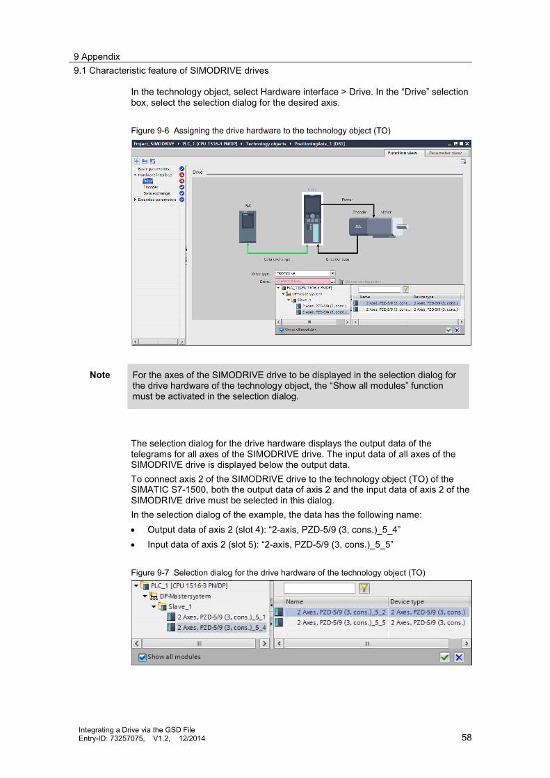
9 Appendix9.1 Characteristic feature of SIMODRIVE drives
Integrating a Drive via the GSD FileEntry-ID: 73257075, V1.2, 12/2014 58
In the technology object, select Hardware interface > Drive. In the “Drive” selectionbox, select the selection dialog for the desired axis.
Figure 9-6 Assigning the drive hardware to the technology object (TO)
Note For the axes of the SIMODRIVE drive to be displayed in the selection dialog forthe drive hardware of the technology object, the “Show all modules” functionmust be activated in the selection dialog.
The selection dialog for the drive hardware displays the output data of thetelegrams for all axes of the SIMODRIVE drive. The input data of all axes of theSIMODRIVE drive is displayed below the output data.To connect axis 2 of the SIMODRIVE drive to the technology object (TO) of theSIMATIC S7-1500, both the output data of axis 2 and the input data of axis 2 of theSIMODRIVE drive must be selected in this dialog.In the selection dialog of the example, the data has the following name: Output data of axis 2 (slot 4): “2-axis, PZD-5/9 (3, cons.)_5_4” Input data of axis 2 (slot 5): “2-axis, PZD-5/9 (3, cons.)_5_5”
Figure 9-7 Selection dialog for the drive hardware of the technology object (TO)

9 Appendix9.1 Characteristic feature of SIMODRIVE drives
Integrating a Drive via the GSD FileEntry-ID: 73257075, V1.2, 12/2014 59
NOTICE Make sure that the selection of output and input data (slots) of the relevantaxis is consistent.
Otherwise, an unexpected response of the axis may occur due toerroneous data transfer between the technology object (TO) and the drive.
9.1.5 Checking the drive connection via the technology object
After assigning the drive hardware to the respective technology object (TO), theaddresses for data exchange parameterized in the technology object shouldalways be checked via the selected telegram.In the context menu of the technology object (TO), open the object in the blockview in the DB editor of the Totally Integrated Automation Portal (TIA Portal).
Figure 9-8 Opening the technology object (TO) in the block view in the DB editor

9 Appendix9.1 Characteristic feature of SIMODRIVE drives
Integrating a Drive via the GSD FileEntry-ID: 73257075, V1.2, 12/2014 60
The data block structure of the technology object (TO) lists the parameterizedaddresses for the input and output data of the telegram connection for theSIMODRIVE drive in the Base > Static > Actor > Interface path: The address entered in “AdressOut” must match the start address of the output
data area of the telegram of the desired axis.In the example shown here, this means for axis 2:– Entered address “AdressOut” = 10– Start address of the output data area of the telegram = 10…19
The address entered in “AdressIn” must match the start address of the inputdata area of the telegram of the desired axis.In the example shown here, this means for axis 2:– Entered address “AdressIn” = 18– Start address of the input data area of the telegram = 18…35
Figure 9-9 Addresses for the output and input data in the technology object (TO)
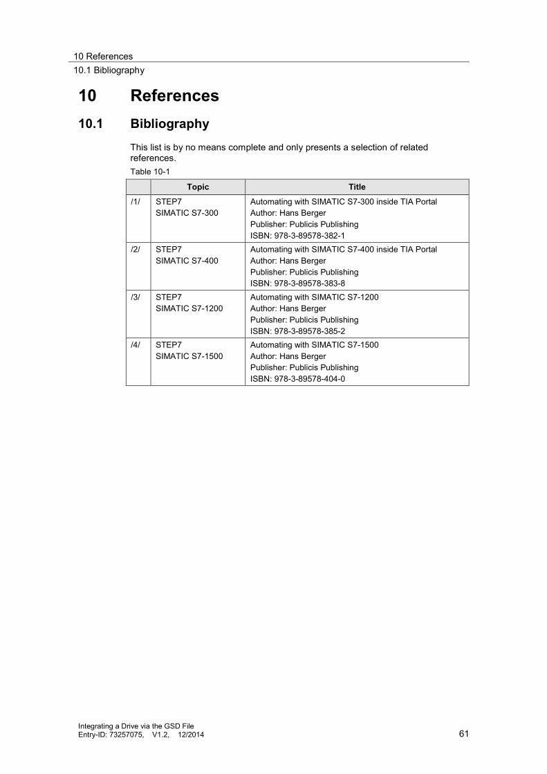
10 References10.1 Bibliography
Integrating a Drive via the GSD FileEntry-ID: 73257075, V1.2, 12/2014 61
10 References10.1 Bibliography
This list is by no means complete and only presents a selection of relatedreferences.Table 10-1
Topic Title
/1/ STEP7SIMATIC S7-300
Automating with SIMATIC S7-300 inside TIA PortalAuthor: Hans BergerPublisher: Publicis PublishingISBN: 978-3-89578-382-1
/2/ STEP7SIMATIC S7-400
Automating with SIMATIC S7-400 inside TIA PortalAuthor: Hans BergerPublisher: Publicis PublishingISBN: 978-3-89578-383-8
/3/ STEP7SIMATIC S7-1200
Automating with SIMATIC S7-1200Author: Hans BergerPublisher: Publicis PublishingISBN: 978-3-89578-385-2
/4/ STEP7SIMATIC S7-1500
Automating with SIMATIC S7-1500Author: Hans BergerPublisher: Publicis PublishingISBN: 978-3-89578-404-0

10 References10.2 Internet links
Integrating a Drive via the GSD FileEntry-ID: 73257075, V1.2, 12/2014 62
10.2 Internet links
This list is by no means complete and only provides a selection of usefulinformation.Table 10-2
Topic Title
\1\ Reference to theentry
http://support.automation.siemens.com/WW/view/en/73257075
\2\ Siemens IndustryOnline Support
http://support.automation.siemens.com
\3\ Information on theTIA Portal
TIA Portalhttp://www.industry.siemens.com/topics/global/en/tia-portal/Pages/default.aspx
Controller Software in the TIA Portal – SIMATIC STEP 7http://www.industry.siemens.com/topics/global/en/tia-portal/controller-sw-tia-portal/Pages/Default.aspx
\4\ Information on theSIMATIC S7-1500
SIMATIC S7-1500http://www.automation.siemens.com/mcms/programmable-logic-controller/en/advanced-controller/s7-1500/Pages/default.aspx
\5\ STARTERcommissioningtool
SINAMICS MICROMASTER STARTER (Download)http://support.automation.siemens.com/WW/view/en/26233208
\6\ SINAMICSStartdrive STEP 7option
SINAMICS STARTDRIVEhttp://www.automation.siemens.com/mcms/mc-solutions/en/engineering-software/startdrive/Pages/startdrive.aspx
\7\ GSDML files forPROFINET -download
SINAMICS S120http://support.automation.siemens.com/WW/view/en/49217480SINAMICS S150, G130/G150, GM150/GL150/SL150/SM120,DCM, DCPhttp://support.automation.siemens.com/WW/view/en/98207877SINAMICS G120http://support.automation.siemens.com/WW/view/en/26641490
\8\ GSD filesfor PROFIBUS –download
SINAMICS S120http://support.automation.siemens.com/WW/view/en/49216293SINAMICS S150, G130/G150, GM150/GL150/SL150/SM120,DCM, DCPhttp://support.automation.siemens.com/WW/view/en/98206128SINAMICS S110http://support.automation.siemens.com/WW/view/en/42705323SINAMICS G120 / G120Phttp://support.automation.siemens.com/WW/view/en/23450835SINAMICS G120Chttp://support.automation.siemens.com/WW/view/en/60292416SINAMICS G120Dhttp://support.automation.siemens.com/WW/view/en/60292521
Paket SIMODRIVE 611U V14.2http://support.automation.siemens.com/WW/view/en/103498340(The GSD files are in the toolbox)