Embed Size (px)
Citation preview
1
1
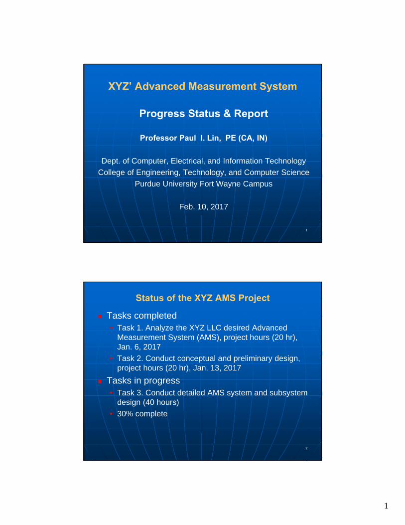
XYZ’ Advanced Measurement System
Progress Status & Report
Professor Paul I. Lin, PE (CA, IN)
Dept. of Computer, Electrical, and Information Technology
College of Engineering, Technology, and Computer Science
Purdue University Fort Wayne Campus
Feb. 10, 2017
2
Status of the XYZ AMS Project
Tasks completed• Task 1. Analyze the XYZ LLC desired Advanced
Measurement System (AMS), project hours (20 hr), Jan. 6, 2017
• Task 2. Conduct conceptual and preliminary design, project hours (20 hr), Jan. 13, 2017
Tasks in progress• Task 3. Conduct detailed AMS system and subsystem
design (40 hours)
• 30% complete
2
3
Status of the XYZ AMS Project
Tasks to be started• Task 4: AMS Subsystem Testing and Software
Development, 60 hr; estimate starting date Feb. 12, 2017
• Task 5: AMS System Integration and Testing, 60 hr; estimate starting date March 27, 2017
• Task 6: AMS System Production and Final Testing and Debugging, 20 hr; estimate starting date April 24, 2017
• Task 7: Documentation and Reporting: Final Project Report, 20 hr ; estimate starting date May 18, 2017
4
Status of the XYZ AMS Project (cont.)
Task 1. Analyze the XYZ LLC desired Advanced Measurement System (AMS)
Est starting date 12/5/2016, actual starting date 12/9/2016, completed 1/6/2017, project hours: 20 hours
Deliverables• Analysis Report of Advanced Measurement System,
reviewed and approved, Jan. 6, 2017
• PPT slide and presentation reviewed on Jan. 6, 2017
3
5
Status of the XYZ AMS Project (cont.)
Task 2. Conduct conceptual and preliminary design
a) AMS system architecture design
b) Interface, communication and networking
c) Signal conditioning
d) Data storage and flow
e) Database design
6
Status of the XYZ AMS Project
Task 2. Conduct conceptual and preliminary design (continue..)
Est start date Dec. 14, 2016; actual starting date Jan. 6, 2017; completed date Jan. 13, 2017; total project hours allocated: 20 hours
Deliverables• Conceptual & Preliminary Design Report of Advanced
Measurement System, Jan. 12, 2017
• PPT slide with presentation and review, Jan. 13, 2017
4
7
Status of Tasks
Tasks 3 - Conduct detailed AMS system and subsystem design (40 hours)• In progress, 30% complete
Completed subtasks• NI USB 6501 DIO Device Installation, Testing,
through NI device monitor, Installation and testing report submitted 2017/2/1
• HiPot-to-LabVIEW Interface Circuit using NI USB 6501, interface design and verification report submitted 2017/2/1
8
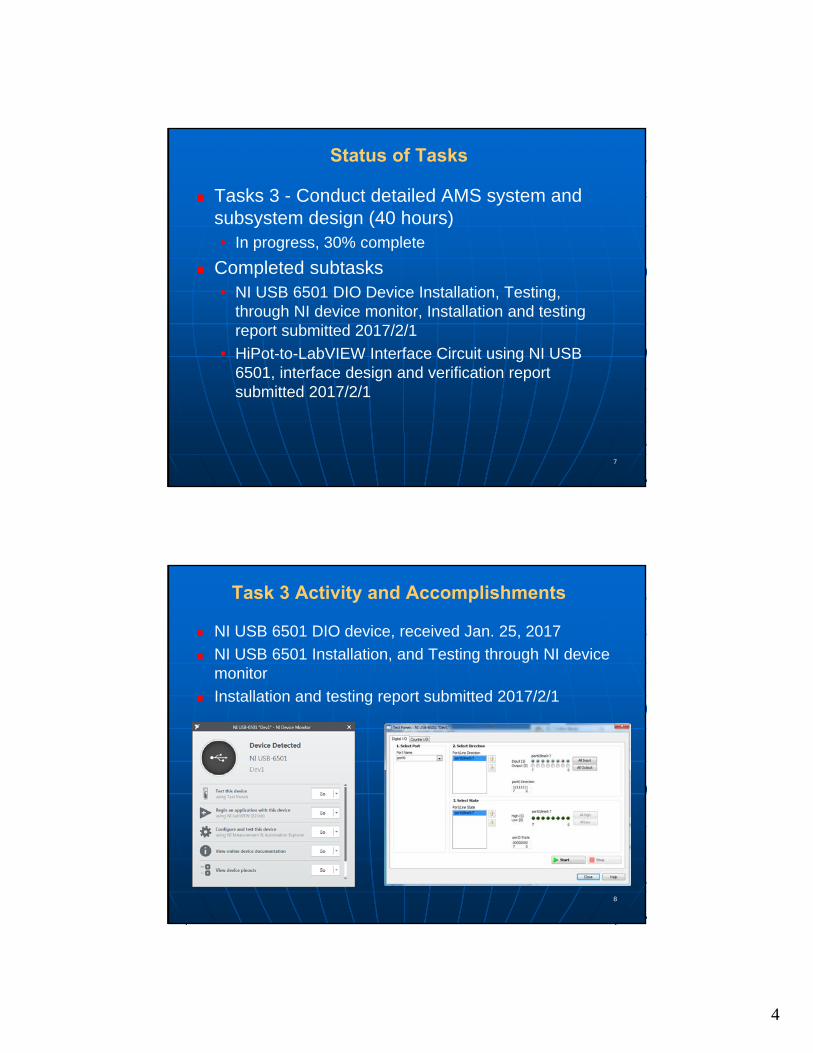
Task 3 Activity and Accomplishments
NI USB 6501 DIO device, received Jan. 25, 2017
NI USB 6501 Installation, and Testing through NI device monitor
Installation and testing report submitted 2017/2/1
5
9
Task 3 Activity and Accomplishments
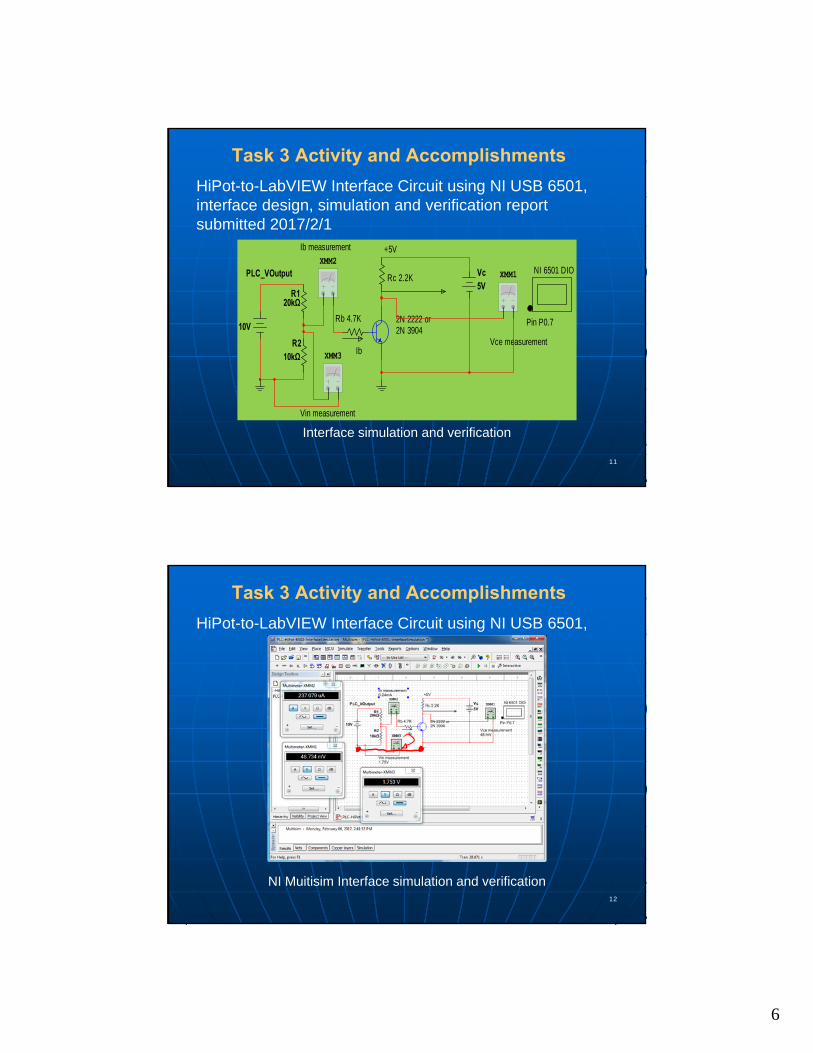
HiPot-to-LabVIEW Interface Circuit using NI USB 6501, interface design, simulation and verification report submitted 2017/2/1
An interface circuit for HiPot equipment and NI 6501
R210kΩ
R120kΩ
PLC_VOutput
10V
+5V
2N 2222 or2N 3904
NI 6501 DIO
Pin P0.7Rb 4.7K
Rc 2.2K
Ib
10
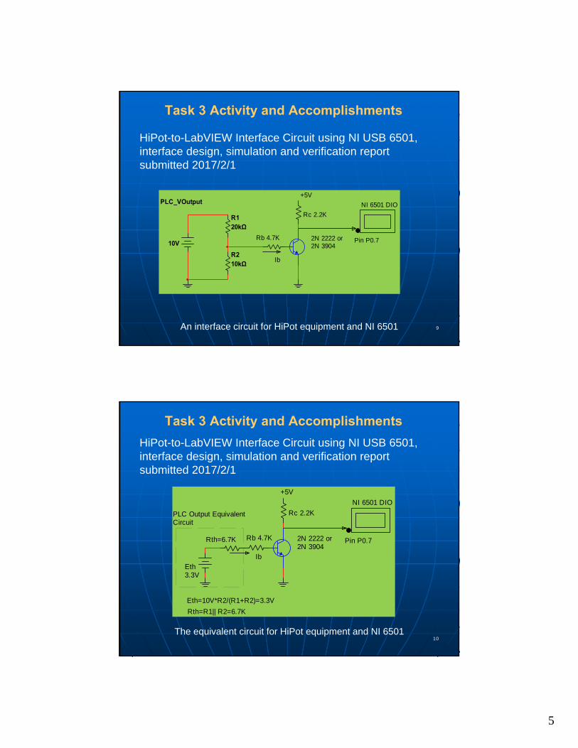
Task 3 Activity and Accomplishments
HiPot-to-LabVIEW Interface Circuit using NI USB 6501, interface design, simulation and verification report submitted 2017/2/1
The equivalent circuit for HiPot equipment and NI 6501
Eth=10V*R2/(R1+R2)=3.3V
Rth=R1|| R2=6.7K
Rth=6.7K
Eth3.3V
+5V
2N 2222 or2N 3904
NI 6501 DIO
Pin P0.7Rb 4.7K
Rc 2.2K
Ib
PLC Output EquivalentCircuit
6
11
Task 3 Activity and Accomplishments
HiPot-to-LabVIEW Interface Circuit using NI USB 6501, interface design, simulation and verification report submitted 2017/2/1
Interface simulation and verification
R210kΩ
R120kΩ
PLC_VOutput
10V
+5V
2N 2222 or2N 3904
NI 6501 DIO
Pin P0.7Rb 4.7K
Ib
XMM1Vc5V
XMM2
Vce measurementXMM3
Vin measurement
Ib measurement
Rc 2.2K
12
Task 3 Activity and Accomplishments
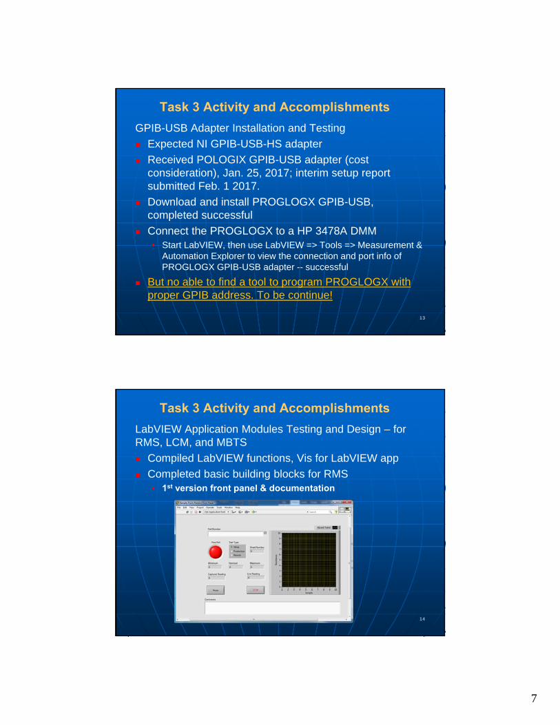
HiPot-to-LabVIEW Interface Circuit using NI USB 6501,
NI Muitisim Interface simulation and verification
7
13
Task 3 Activity and Accomplishments
GPIB-USB Adapter Installation and Testing
Expected NI GPIB-USB-HS adapter
Received POLOGIX GPIB-USB adapter (cost consideration), Jan. 25, 2017; interim setup report submitted Feb. 1 2017.
Download and install PROGLOGX GPIB-USB, completed successful
Connect the PROGLOGX to a HP 3478A DMM• Start LabVIEW, then use LabVIEW => Tools => Measurement &
Automation Explorer to view the connection and port info of PROGLOGX GPIB-USB adapter -- successful
But no able to find a tool to program PROGLOGX with proper GPIB address. To be continue!
14
Task 3 Activity and Accomplishments
LabVIEW Application Modules Testing and Design – for RMS, LCM, and MBTS
Compiled LabVIEW functions, Vis for LabVIEW app
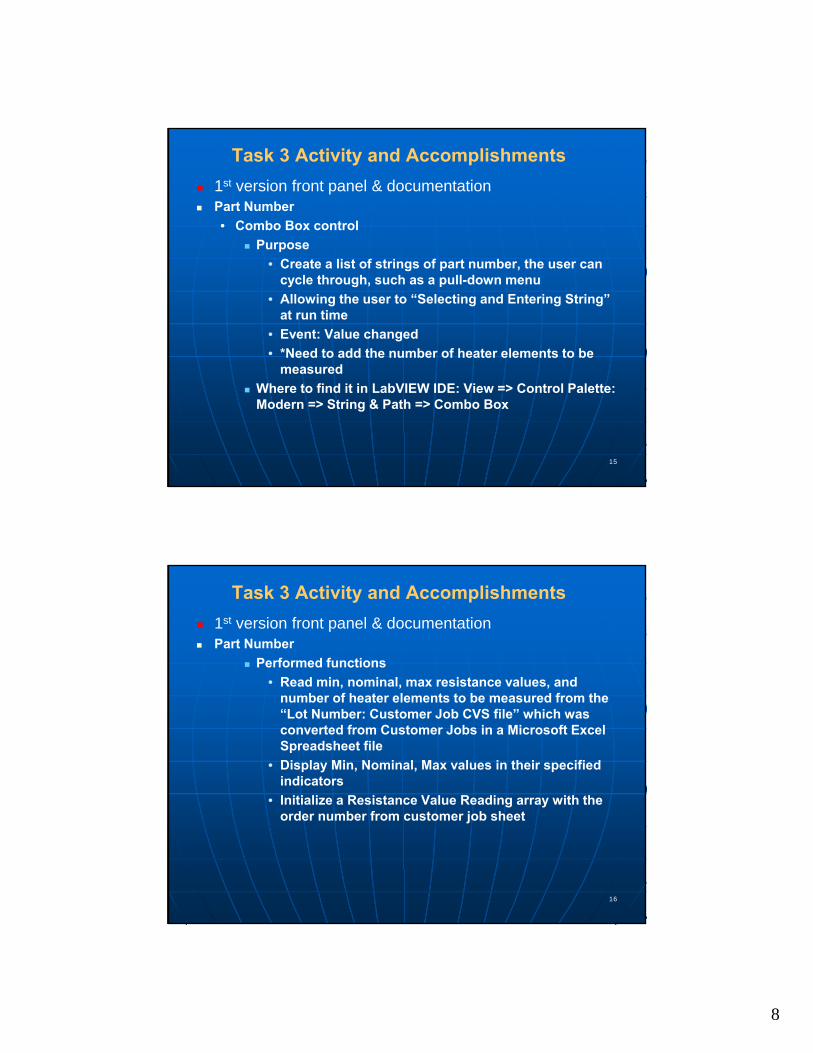
Completed basic building blocks for RMS• 1st version front panel & documentation
8
15
Task 3 Activity and Accomplishments
1st version front panel & documentation Part Number
• Combo Box control
Purpose
• Create a list of strings of part number, the user can cycle through, such as a pull-down menu
• Allowing the user to “Selecting and Entering String” at run time
• Event: Value changed
• *Need to add the number of heater elements to be measured
Where to find it in LabVIEW IDE: View => Control Palette: Modern => String & Path => Combo Box
16
Task 3 Activity and Accomplishments
1st version front panel & documentation Part Number
Performed functions
• Read min, nominal, max resistance values, and number of heater elements to be measured from the “Lot Number: Customer Job CVS file” which was converted from Customer Jobs in a Microsoft Excel Spreadsheet file
• Display Min, Nominal, Max values in their specified indicators
• Initialize a Resistance Value Reading array with the order number from customer job sheet
9
17
Task 3 Activity and Accomplishments
LabVIEW Application Modules Testing and Design – for RMS, LCM, and MBTS
Compiled LabVIEW functions, Vis for LabVIEW app
Completed basic building blocks for RMS• 1st version front panel & documentation
• RMS configuration
GPIB address (default 23) for DMM
Configuration file in CVS; read from hard drive
• LabVIEW – data & control structures Local and Global variables, Shared variables
Numeric, String
Array, Matrix & Cluster
While, For, Case, Flat Sequence
18
Task 3 Activity and Accomplishments
Completed basic building blocks for RMS (cont.)
• LabVIEW – File I/O & String Number Conversions Spreadsheet LabVIEW
CSV file LabVIEW
Read/Write Measurement File
File Path
Resistance min, nominal, max value extraction from configuration file
String Numeric Value conversions
While, For, Case, Flat Sequence
10
19
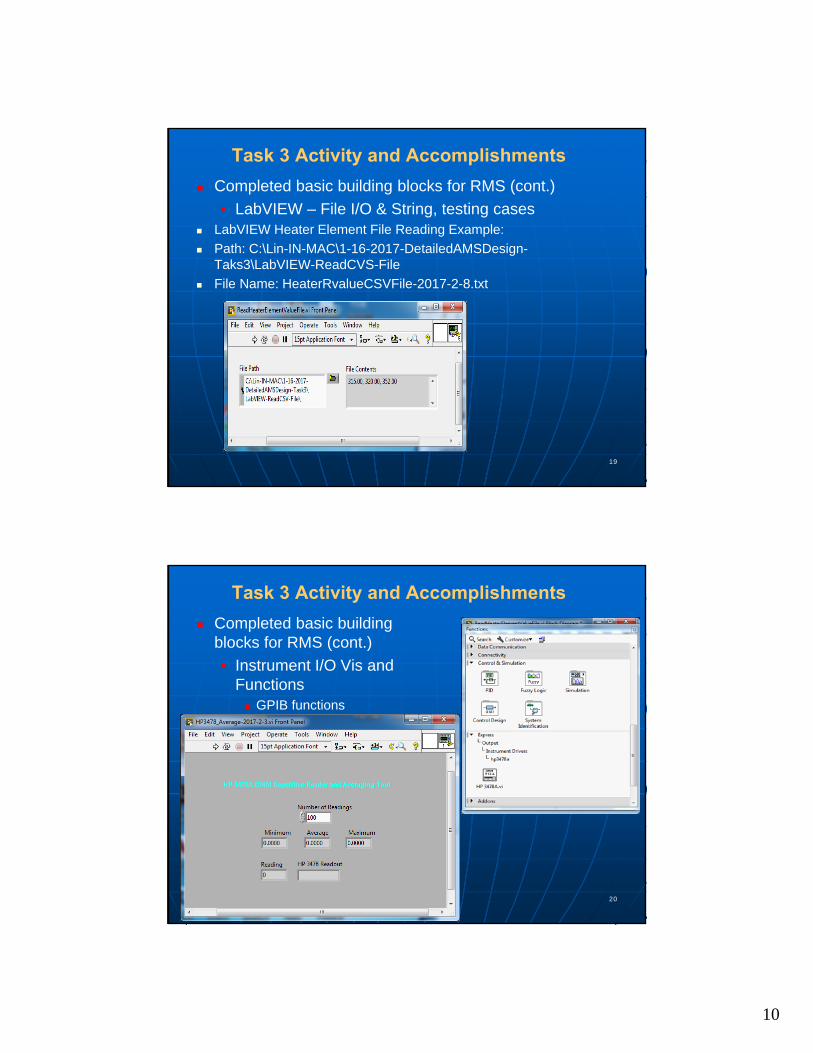
Task 3 Activity and Accomplishments
Completed basic building blocks for RMS (cont.)
• LabVIEW – File I/O & String, testing cases LabVIEW Heater Element File Reading Example:
Path: C:\Lin-IN-MAC\1-16-2017-DetailedAMSDesign-Taks3\LabVIEW-ReadCVS-File
File Name: HeaterRvalueCSVFile-2017-2-8.txt
20
Task 3 Activity and Accomplishments
Completed basic building blocks for RMS (cont.)
• Instrument I/O Vis and Functions GPIB functions
11
21
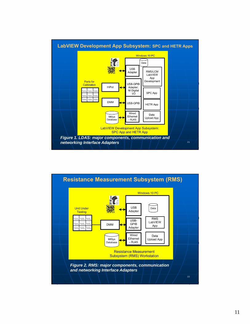
LabVIEW Development App Subsystem: SPC and HETR Apps
Figure 1. LDAS: major components, communication and networking Interface Adapters
22
Resistance Measurement Subsystem (RMS)
Figure 2. RMS: major components, communication and networking Interface Adapters
12
23
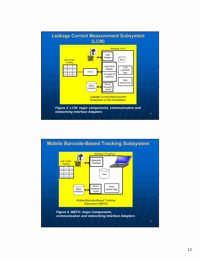
Leakage Current Measurement Subsystem (LCM)
Figure 3. LCM: major components, communication and networking Interface Adapters
24
Mobile Barcode-Based Tracking Subsystem
Figure 4. MBTS: major components, communication and networking Interface Adapters


![Understanding Communication and Language Needs of Medicare Beneficiaries · PDF file[7 /XYZ 70 498 0.00] [9 /XYZ 70 363 0.00] [13 /XYZ 70 348 0.00] [17 /XYZ 70 621 0.00] [19 /XYZ 70](https://img.pdfslide.us/doc/110x75/5a8687117f8b9a001c8d1dc7/understanding-communication-and-language-needs-of-medicare-beneficiaries-7-xyz.jpg)