Embed Size (px)
Citation preview

XXXI. NETWORK SYNTHESIS
Prof. E. A. Guillemin R. O. Duda H. B. Lee, Jr.S. G. Chamberlain A. I. Grayzel W. C. Schwab
RESEARCH OBJECTIVES
The effectiveness of methods of approach to the synthesis problem as reported inlast year's research objectives is being explored in greater detail. The detailed reportsgiven below are specific steps in this evaluation process. The further development ofan approach and its implementation will absorb our efforts for some time to come; andit is our expectation that many collateral problems will be generated in the process.Already the results of this work have clarified aspects of network theory which repre-sent gaps in classical linear dynamics. The development of network theory seems to beon the threshold of a new phase that promises to be at least as significant as the one thatyielded our present state of accomplishment in synthesis.
E. A. Guillemin
A. A NORMAL FORM FOR A MATRIX PERTINENT TO RLC NETWORKS
WITHOUT MUTUAL INDUCTANCE
Guillemin1 has shown how the problem of finding the normal coordinate transforma-
tion for a network with an arbitrary loss function can be reduced to that of simultane-
ously diagonalizing two matrices, and has indicated the value of this result for a more
general approach to network synthesis. Desoer pointed out that the equations for any
linear circuit can always be cast in the Peano-Baker form
y = Ay + f (1)
and showed how the eigenvectors of the matrix A can be identified with modal behavior.
Another formulation of the problem, which possesses certain advantages for synthe-
sis applications, can be obtained from a combination of these methods. The familiar
nodal- equilibrium equations
(sC+G+-l) e= i (2)
are rewritten as
(sC+G) + = i (3)
r e- srX = 0 (4)
or, in partitioned form,
S. = . . (5)S r -s sr i
Thus the network is described by the two real symmetric matrices
337

(XXXI. NETWORK SYNTHESIS)
C: 0 G: r
0 -r r
which are related to the network in a familiar way. If ' is nonsingular, this constitutes
the desired formulation of the problem. In most cases, however, X is not uniquely
defined by Eq. 4 and thus the description is singular. This difficulty can be avoided by
using the following technique:
(a) Number inductive branches consecutively from 1 to b .
(b) Choose a tree that is such that all inductive branch voltages are determined by
inductive tree-branch voltages.
With this choice of variables, it follows that r can be partitioned into the form
r :L 1 ] (6)
in which r' is nonsingular if b is not zero. When this result is substituted in Eq. 5 and
the superfluous equations and variables are deleted, the following reduced description is
obtained:
sC + G " e0 (7)
' o :-sr, J o
Defining M(s) as
M(s) = sM 1 + M 2 (8)
where
C o
M1 -'1 (9)
and
M.= i 0 (10)
by the formulas of Schur (3), we have
338

(XXXI. NETWORK SYNTHESIS)
IM(s)l = -sr' IsC+ G+ 1 rl(11)s
so that if the network is connected, M(s) is nonsingular. It follows from Eq. 7 that the
inverse of M(s) can be partitioned in such a manner that its upper left-hand corner is a
matrix of open-circuit impedance parameters (z parameters) for the network.
Let Mn(s) denote the normal form of M(s) under a congruence transformation, and
let A denote the nonsingular transformation matrix. Then
AtM(s) A = M (s) (12)
M( = AM 1 (s) A (13)(s) n V
If
M-1 =[z..]M-(s) ij
n 13
and
A= [a..],
then
z.. = a a a. ) (14)
p. V
which reduces to a particularly simple form if Mn(s) is diagonal.
The problem of reducing a pencil of symmetric matrices sM 1 + M 2 to a normal form
by a congruence transformation is somewhat complicated if neither M 1 nor M 2 is definite
or semidefinite. The general solution has been given by Gantmacher,4 and a special case
of this result pertains to the network situation. The following discussion of the normal
form is limited to a brief description and physical interpretation.
The simplest situation occurs if the roots of the characteristic equation
IM(s)I = 0 (15)
are distinct and equal in number to the order of M(s). For each root s i there exists an
eigenvector qi satisfying
M(si) i = 0 (16)
and having the properties
t-M- = 6 (17)1i I j 6ij
339

(XXXI. NETWORK SYNTHESIS)
qitM2q = -si6ij. (18)
These eigenvectors are directly associated with the modal behavior of the network, their
components giving the distribution pattern of voltages and flux linkages corresponding to
each natural mode. They appear as the columns of the transformation matrix A,
resulting in the normal form
s - s1 0
Mn(s) = 0 s (19)
0 s-sm
The occurrence of multiple-order roots and/or the lack of a sufficient number of
roots result in a more complicated normal form. Multiple-order roots arise from two
distinctly different physical situations: (a) the presence of two "uncoupled" parts of the
network which happen to have the same natural frequency, or (b) the presence of an
impedance with a multiple-order pole. The former case leads to a normal form con-
taining a submatrix of the form
AMd= , (20)
0 s - s
while the latter case leads to a normal form that contains a submatrix of the form
0 s - s.1
A1M = (21)
m. s- s.1 1
s -s. 1 01
Since
10
s - S.
x- 1M = (22)d.1
0 1s - s.
1
340

(XXXI. NETWORK SYNTHESIS)
while
M =m.1
( i.+1(-s1)
(s-s.)-1
-12
(s-s.)
1(s-s.)
1(s-s.)1
1(s-s.)
(23)
the difference between these two cases is clearly reflected in the driving-point and trans-
fer impedances given by Eq. 14.
If any of the driving-point or transfer impedances have resistive or inductive high-
frequency behavior, then the degree of the characteristic equation is less than the order
of M(s). As special cases, both purely resistive and purely inductive networks have
zero-degree characteristic equations. The physical difference between resistive and
inductive high-frequency behavior is reflected in the two different types of submatrices
in the normal form,
(24)
and
0 1
1 s
(25)
The submatrices given by Eqs. 20, 21, 24, and 25 appear on the principal
diagonal of the normal form, the remaining elements being zeros. Although a
rigorous proof has not yet been obtained, it is believed that this represents
a complete description of the normal form for the case of an RLC network
without mutual inductance. Thus,
341
AM =
r
0

(XXXI. NETWORK SYNTHESIS)
- d
AMM
M
EXAMPLE 1
e
8iFig. XXXI- 1.
For the circuit shown in Fig. XXXI-1,
C= 1 G
8s 0
0 9M(s) =
24 -24
-24 27
IM(s) = 5184 (s+1)
0 01L0 9]24 -24
-24 27
-24s 24s
24s -27s
3
1 .
8 3
964
2 . 1. 1 .- - -16 J
1 . 3 . 15 .
2 . 1 . 11 .3j 6J 48J
Mn(s) = (26)
-24
27
0
13
0
0
342
24r=-24

(XXXI. NETWOEK SYNTHESIS)
0
At MA =+
0
0 s+1 0
s+l 1 0
0 0 1
- - .-\VN~ci
i ig. XI-
1 1 1 -1 01
S-1
i)0 -1 '
0 1 -I
-s
s+ 1 0 0
0 -s s
0 s s
FT= -0
0
'C; , -
j 1 j oj 0 j 0
C) C jS 0 -
0 0 0
343
i 0
L
1
i-i
M(s) = 0
1
- [
-1 01
2 9
0 OJ
E;i
UI i
i;

(XXXI. NETWORK SYNTHESIS)
AtMA =
s+1 0 0 0 0
0 s+l1 0 0 0
0 1 0 0
0 0 0 1
0 0 1 s
These two
and f. This
z..ij =
In Example 1,
examples illustrate the need for each of the submatrices M d , M , M ,
need is associated with the partial fraction expansion
a. a. zn(n ) (14)
V
s(s+3)11 3
8(s+1)
s(s +3)
2 2 9 39(s+l)
-1
4(s+1)
-4
9(s+1)
1 18(s+)2 8(s+l)
8(s+1)
2
3(s+1)
1 13(s+1) 9'
The third-order pole requires the presence of M m in the normal form, while the resis-A
tive high-frequency behavior of z22 accounts for M r . In Example 2,
s(s+2)z = - s+ 111 s+ 1 s+ 1
z 2 2 = S = S
s + s + 133 s + 1
1s+1s+l1
The multiple-order root in the characteristic equation is due to the two uncoupled cir-A
cuits with the same natural frequency; thus Md appears in the normal form. The con-A
stant term in the partial fraction expansion leads to M r , and the term proportional toA
frequency leads to M 2 .
While the normal form for RLC networks is more involved than the diagonal form
in the two-element-kind case, these examples emphasize the need for a more complex
normal form and illustrate its physical interpretation.
R. O. Duda
344

(XXXI. NETWORK SYNTHESIS)
References
1. E. A. Guillemin, The normal coordinate transformation of a linear system withan arbitrary loss function, J. Math. Phys. 39, 97-104.
2. C. A. Desoer, Modes in linear circuits, Trans. IRE, Vol. CT-7, pp. 211-225,1960.
3. F. R. Gantmacher, Matrix Theory, Vol. I (Chelsea Publications, Inc., New York,1959), p. 46.
4. F. R. Gantmacher, Matrix Theory, Vol. II, op. cit., Chapter XII.
B. SYNTHESIS OF TWO-ELEMENT-KIND NETWORKS BY MEANS OF
COORDINATE TRANSFORMATIONS
The ability to synthesize two-element-kind networks by means of coordinate trans-
formations is greatly simplified by possession of the ability to diagonalize the nodal
parameter matrices pertinent to such networks.1 The existence of dynamical degener-
acies in a network quite often leads to singularity of both the parameter matrices and
renders them both positive semidefinite. Despite the statement that two real, symmet-
rical, singular matrices cannot, in general, be simultaneously diagonalized, we shall
show that for two-element-kind electrical networks a simultaneous diagonalization can
always be effected in a straightforward manner by means of a congruent, nonsingular,
real, transformation.
1. Dynamical Degeneracies and Their Relation to Nodal Parameter Matrices
We shall concern ourselves with LC networks in which there are no tightly coupled
mutual inductances. Furthermore, we shall assume an n independent node network
consisting of a single part; that is, every node is connected to the network tree by at
least one branch. As usual, we shall assume that each individual element constitutes
a branch. Once certain results have been established for LC networks, extension to
RC and RL networks will be trivial.
We recall that, on a nodal basis, the number of dynamically independent variables
characterizing an LC network equals the number of topologically independent variables
required to specify uniquely the equilibrium for the network, reduced by the num-
ber of independent constraints existing among these variables.
On a nodal basis, constraints among the dynamic variables are revealed through the
presence of one-element-kind cut-sets in the network. Thus, the existence of a cut-set,
all of whose branches are capacitors, leads to a constraint among the dynamic variables.
Similarly, the presence of a pure inductive cut-set leads to a constraint. On a nodal
basis, one-element-kind cut-sets furnish the only situations that give rise to dynami-
cal constraints. Hence, if a network has n independent node pairs and contains
345

(XXXI. NETWORK SYNTHESIS)
a- independent, pure capacitive cut-sets and K independent, pure inductive cut-sets, the
number cf dynamically independent variables is exactly (n--kX). 2
It is weil known that the number of dynamically independent variables is just equal
to the nunber of nonzero, noninfinite, natural frequencies displayed by the network.
(Note that here the range of natural frei -.ies is defined from zero to plus infinity.
-:r instance, a parallel LC tank circuit hs :, natural frequency.)
OrL physical grounds we may r-gard natural frequencies of a network as those fre-
cuencie3s at which a voltage may exist across br- nches in the network even though there
-s no current source exciting the network. If we consider from this point of view those
branches in a network which comprise a pure capacitive cut-set, it is easy to see that
when we place an appropriate charge on each of these capacitors, so that the voltages
across these capacitors are all identical, no currents will flow and the charges will
remain stationary. This can be seen to be true because at zero frequency the inductors
appear as short circuits, and therefore all of the capacitors of a given cut-set appear
rn parallel with each other. Hence, if there are - independent, pure capacitive cut-sets
i-r the network, there are evidently ac different topological situations in which a zero
frequency voltage can exist without any external current excitation. It seems reasonable,
then, to assert that each independent capacitive cut-set gives rise to a natural frequency
at zero.
If we should consider exciting the network across an inductive cut-set with a current
source operating at as high a frequency as we please, it is clear that the capacitive
branches essentially become short circuits and that the inductances associated with this
inductive cut-set are all effectively in parallel. If we then increase the frequency and
at the same time decrease the amplitude of the excitation in such a manner as to keep
the voltage across these inductive branches essentially constant in amplitude, it is clear
that in the limit, as the frequency approaches infinity, the amplitude of the excitation
approaches zero, but the voltage remains nonzero and finite. Hence, in a limiting sense,
we recognize that an inductive cut-set can be thought of as giving rise to a natural fre-
quency at infinity. We see, just as before, that if there are K independent inductive
cut-sets in the network, there are K different topological situations in which infinite
natural frequencies arise. Thus it seems reasonable to assert that each independent
inductive cut-set gives rise to a natural frequency at infinity.
If we agree to follow the line of reasoning presented above, we may state that a net-
work containing n independent nodes, a- independent, capacitive cut-sets and X inde-
pendent, inductive cut-sets has a natural frequencies at zero, K natural frequencies
at infinity, and (n-a--k) nonzero, noninfinite natural frequencies. To confirm the cor-
rectness of such an interpretation, we point out that the natural frequencies of a network
are the latent roots of the nodal admittance matrix of the network and appear as factors
in the determinant of this matrix. If, as usual, we let s represent the complex
346

(XXXI. NETWORK SYNTHESIS)
frequency variable, and let C and r represent the nodal capacitance and reciprocal
inductance matrices, respectively, we may write Y, the nodal admittance matrix as
Y = sC + s ' (1)s
The properties of the determinant, IY , in which we are interested, may be found by
inspection. IYI is the sum of all of the possible "tree values" associated to the network,
where a "tree value" is the product of all of the branch admittances forming a particular
tree. Since every tree connects to all of the nodes in the network, it is clear that every
tree must contain at least one branch from every one of the o independent capacitive
cut-sets, and at least one branch from every one of the X independent inductive cut-sets.
Hence, every "tree value" contains the common factors (s) and (s ). If we denote by t.the various tree values, with the understanding that the common factors mentioned above
have been factored out, we may write
p
IY( = (s)() t. p = number of trees. (2)
j=1
We recognize that since there are n branches in every tree, a typical term such as
t must be the product of exactly (n-o-k) admittances. We also recognize that L tj,j= 1
which is a ratio of polynomials in s, accounts for the nonzero, noninfinite natural fre-
quency factors and may be written aside from a constant multiplier, as a product of
factors of the form (s + , where y- are constants.
(n-o--x) ( " _Y = k(s) s + (3)s = 1
Here, k = a constant.
Equation 3, provided that we do not make any cancellation of factors, shows that
there are always exactly n factors in the determinantal expression. Since these factors
represent the latent roots of the admittance matrix, Y, we should expect that if Y can
be reduced to a diagonal canonic form by means of a nonsingular coordinate transfor-
mation, these same factors should appear as the diagonal entries in such a matrix. We
shall show in the next section that, in fact, this is just what happens. However, first,
we also wish to demonstrate how the presence of one-element-kind cut-sets relates to
the rank of the individual C and F matrices.
That which we wish to show is made evident by inspection when we use general cut-
sets to define the nodal parameter matrices. Construction of the nodal parameter
matrices in this general manner is quite similar to the construction on a node-to-datum
347
(XXXI. NETWORK SYNTHESIS)
basis, with which everyone is quite familiar. In the general cut-set formulation, coupling
between one cut-set and another is brought about in two says. In forming a cut-set we
can imagine that we pick up certain nodes in, say, our right hand and grasp all other
nodes in our left hand. The voltage rise is from left hand to right hand. If we then pull
our hands apart, certain branches are stretched; these branches form the cut-set.
Hence, any two cut-sets may have some common "picked-up" nodes and some common
branches. The latter may or may not connect to common "picked-up" nodes. The admit-
tances of those common branches that do connect to such common "picked-up" nodes
contribute to the mutual coupling with plus signs, while the admittances of the remaining
common branches that do not connect to common nodes contribute with minus signs. As
usual, the diagonal entries in the nodal admittance matrix represent the total admittance
of the branches forming the cut-set, and the mutual coupling between cut-sets appears
in the appropriate, symmetrical off-diagonal positions. One recognizes that the node-
to-datum formulation is just a special case of the more general procedure.
Now, if we have an n independent node network containing ac independent capacitance
cut-sets and X independent inductance cut-sets, there must also be exactly (n-0--X) other
independent cut-sets, which are comprised of both capacitive and inductive branches.
Cut-sets containing both types of branches will be referred to as hybrid cut-sets. It is
clear that the pure capacitive and pure inductive cut-sets are independent of each other
and that their total number, (-c+X), must be less than or equal to n, the total number of
independent cut-sets.
If we choose a set of n independent cut-sets which includes all of the independent
one-element-kind cut-sets, as well as (n---X) hybrid cut-sets, we may number the inde-
pendent capacitive cut-sets 1 through -c, the hybrid cut-sets (-c+l) through (n-X), and the
independent inductive cut-sets (n-X+1) through n. We are now in a position to write
down the reciprocal inductance matrix, I, and the capacitance matrix, C, by inspection.
In the formation of r the first ac rows and columns must all be zeros, for the first ac
cut-sets are pure capacitance ones and hence involve no inductive branches. The
remaining (n-cr) rows and columns of F pertain to hybrid and inductance cut-sets. Thus,
the last (n-c-) diagonal positions must be filled with positive quantities, while the off-
diagonal entries in these last (n-cr) rows and columns are filled in a symmetrical manner,
representing the inductive coupling among the hybrid and inductive cut-sets.
In a similar manner, it is clear that the last X rows and columns of C must
be replete with zeros, for the last K cut-sets are pure inductive ones. The
first (n-k) rows and columns of C pertain to the capacitive and hybrid cut-sets
and thus the first (n-k) diagonal positions are filled with positive quantities, while
the off-diagonal terms represent the capacitive coupling between the capacitive
and hybrid cut-sets.
Therefore we may write C and F in partitioned form as follows:
348

(XXXI. NETWORK SYNTHESIS)
= (n-X)(n-X)
(4)
0 r i'(n-c)(n-c )
The cut-sets used to define the submatrix C are all independent ones and
have nonzero branch capacitance values. Hence, C(n-k)(n-X) must be nonsingular and
pertinent to a positive definite quadratic form. An analogous statement applies to the
submatrix (n)(n Hence, it also is nonsingular and pertains to a positive definite
quadratic form.
Another way of looking at this reveals that if all of the inductors in the independent
inductive cut-sets were replaced by capacitors, then C would be modified only by the
addition of terms in the partitioned spaces formerly occupied by zeros. This modified
matrix is necessarily positive definite, since all nodes in the network would now be con-
nected by capacitors. C(n-k)(n-k) would be a principal minor of this modified matrix,
and hence it would be positive definite itself. Again, an analogous argument applies to
the fact that F(n-)(n-) is also positive definite. Thus, we have the result that the rank
of C is (n-k) and the rank of I7 is (n-cr).
A set of equilibrium equations defined on any independent group of cut-sets may be
transformed to the set of equations defined on any other group of independent cut-sets
by a real, nonsingular congruent transformation. Such a transformation does not change
the rank of the nodal parameter matrices. Hence, we may draw the valid conclusion
that for an n node network containing cr independent capacitive cut-sets and N independ-
ent inductive cut-sets:
(a) The rank of the nodal capacitance matrix is determined by the number of inde-
pendent inductive cut-sets, and is (n-k).
(b) The rank of the nodal reciprocal inductance matrix is determined by number of
independent capacitive cut-sets, and is (n-cr).
(c) The nodal parameter matrices may always be reduced simultaneously to the
forms given in Eq. 4 by a real, nonsingular congruent transformation.
2. Reduction of the Nodal Parameter Matrices to Diagonal Form
Let us assume an n independent node LC network containing no tightly coupled
mutual inductances. The network is assumed to contain a- independent capacitive cut-
sets and N independent inductive cut-sets. The nodal equilibrium equation based on an
arbitrary set of topologically independent variables may be written in matrix notation
as follows:
349

(XXXI. NETWORK SYNTHESIS)
LsC+ rF V = I, (5)
where V and I are column voltage and current matrices, respectively.
We have seen from the previous section that the presence of dynamical degeneracies,
which implies and is implied by the existence of one-element-kind cut-sets, leads to the
fact that both C and F are singular. Quite often the statement is heard that in general
two singular, real symmetric matrices cannot be simultaneously diagonalized. The
objective here is to show that, for two-element-kind networks having no tightly coupled
mutual inductances, a simultaneous reduction to diagonal form can always be carried
out, irrespective of the dynamical degeneracies that exist in the network.
The first step in the reduction is to render C and F simultaneously into the form
of Eq. 4. As we have shown, this can always be accomplished by a real, nonsingular
congruent transformation. Such a transformation really amounts to a redefinition of the
voltage and current variables of expression (5). Denoting the transformation matrix by
A, we have
C 0C, At CA = .............. .......
0 0(6)0 0
r =AtrA o o
where IA 0. We note that the symmetrical submatrices C 1 and F 1(n-x)(n-x) (n-a)(n-o)
are both pertinent to positive definite quadratic forms and hence nonsingular.
It is convenient to repartition C 1 and I 1 in the following manner:
C10
tCC -(n-r-X)
0
0
0 : • ,1F
C
CI 1n 0- )( -- k
(n- o-k }(n-c-- h I
t•~~~ * .. •....•0 r
(n-a--X)x
C I=1
0
0
*0
F(n-r-x)x
xx
350
• % t __ • %

(XXXI. NETWORK SYNTHESIS)
Here, the superscript "t" denotes the transpose.
The total number of independent one-element-kind cut-sets cannot be greater than
the number of independent nodes in the network. Hence,
(n-o--X) > 0 (n-a-) > X (n-X) > a-. (8)
Therefore, it is clear that when the partitioning indicated in (7) is carried out,
C and C r and F1o-o 1(n-a-xk)(n-a-k) xx (n-a-k)(n-a-k)
are all symmetrical positive definite matrices. This follows because these submatrices
are principal minors of C 1 and Fn1 , respectively, which themselves(n-x)(n-x) (n-a-)(n-a-)
are symmetrical positive definite matrices.
The immediate objective of the next step in the procedure is to reduce C 1 and Fl
simultaneously to diagonal partitioned forms by means of a congruent transformation
by using a matrix Q.
U Q(n--)
Q U(n 0 (9)
0 Qx(n---x) U
where U_, U , and U are diagonal unit matrices.
-1Q -C C
(n-a-k) 1 - (n- )
Q= -F-1 t
x(n-a-x) 1 (n--X)X
IQI = U U(-)H UI = 1
The superscript "-1" denotes the inverse.
In particular, it will be noted that since C 1 and FI are nonsingular, we are
guaranteed that the definitions given above will always be valid.
Performing the congruent transformation simultaneously on C l and r l yields
C 2 and F2 as follows:
351

(XXXI. NETWORK SYNTHESIS)
Cz = Qt1Q =
F2 = Qt Q =
C 2
0 C
00
o
0oE(n-a--X)(n-o-X)
0
C(n-cr-x)(n-cr-x)
= C - Cc C1 1-- ) (n ) i-(n-o--X) I0-0- 1
F =xxk lk
22(n-o--)(n-r-)r r- r
1 (n-cr-X)X XX 1 (n-ar-X)X1
The correctness of the results expressed in Eq. 10 may be verified by a direct expan-
sion of the indicated matrix products.
In view of the fact that the congruent transformation performed in (10) cannot change
the rank, nor can it change the positive semidefinite character of the resulting matrices
C 2 and F , it is evident that C2 C2, and F 2 are allo" (no-X)(n-o--X) XX (n-o-X)(n-o-x)
positive definite matrices and hence nonsingular.
The final step in the diagonalization process is now reduced to routine sim-
plicity, for the form of (10) shows that we may treat each of the three cor-
responding diagonal pairs of submatrices in C2 and 2z separately. The ultimate
diagonal form obtained depends on just how we choose to do this. Here we
shall do this in a manner that lends simplicity to the interpretation of the final
result.
We may form the nonsingular transformation matrix, P, as follows:
352
0
0'2
(n-0-k)(n--k)0 xx
S
:12
(10)
where
C2 = C 10-0"

(XXXI. NETWORK SYNTHESIS)
(11)
P 0 o
P-- 0 0
P 0 P(n-0-k)(n--k) P0 : 0 :
Since C and r2 are
tine methods so that
pt C P =U
and
tP F P = U
both positive definite, PTT and PXX may be formed by rou-
IP I 0
IPx' 0.
Since the center diagonal terms in C 2 and F 2 are real, symmetrical and positive3
definite, it is always possible by standard techniques to construct a nonsingular real
matrix P that is such that
tpt C2(_ P(n-cr-x)(n-cr-x) (n-cr-X)(n-a--X)(n-or--) k(--k
(12)'l~-XJ
where the terms y(-+1))
Performing the final
C 3 = P tCp =
r 3 ptz =
Uc3
0
0
Y(-+2)' and so forth are real nonzero, positive quantities.
transformation yields C 3 and r 3 in the following manner:
0 0
U 0
0 O0
0 0a-o-
(0-+1).0
0 0
0
0
(n-x)
0-
where
353
(13)
(cr+l).
(n-0-)(n--k)' n (n_ (n-o--)(n-0--)

(XXXI. NETWORK SYNTHESIS)
IPI = IPaoI IP(n-a-x)(n-a-X) I Ph O.
All of the congruent transformations performed have been real, nonsingular ones.
We may cascade these operations into a single nonsingular matrix denoted by M.
M = AQP, M =PtQtAt, MI 0. (14)
From Eq. 5, we have
YV = sC+- V = I
and by inversion we find the open-circuit impedance matrix Z.
Y- 1l= sC+ 1 r I
-1 sC + 1Z =Y = s +-r[ s
=V
]'
Applying the transformation M congruently to Y yields a diagonal matrix Yd"
(15)
Y = MtyM = MtsC+ 1
Y d = s
sU
0
sU !
M = s[MtCM] + 1 [MtrM]s
0 O 0
U 0
0 0.XX
15
00-0"
0 :(cr+1) .
o
0
+ y'c+1)s )
0
sY(n+ 's
1suk
; YI = MYd M,
0
(n-x)
Ux
Since
(16)
MtyM
354
0

(XXXI. NETWORK SYNTHESIS)
we find that
U 0 0s a-
1
1s + s tZ= Y =M 0 0 M
s+ (n-k)s
0 0 sU
(17)
Equation 16 bears out the earlier contention that even though the network may exhibit
dynamical degeneracies, which cause both parameter matrices to be singular, a diago-
nalization may always be effected by means of a real, nonsingular transformation. Also,
comparison of Eqs. 3 and 16 reveals that all of the factors in Eq. 3 are diagonal entries
in Yd as we should expect, since the determinant of Yd is just equal to some nonzero
constant times the determinant of Y. In a situation in which both parameter matrices
are nonsingular it is correct to regard the frequency (that is, the value of s) at which
a particular diagonal entry in Yd is zero as being a natural frequency of the system. It
seems reasonable to extend this concept to the general situation and regard zero and
infinity as legitimate natural frequencies also.
Going a step further, we may denote the entries in M, which are all real quantities,
by mjk and write
m11 ml2 • . . mln
M = m 2 1 (18)
mn 1 . . . . . . . . . . . . . . . mnn
From the form of Eq. 17 it can be seen that the open-circuit impedance matrix, Z,
has the form of a Gramian. Hence, if we make the identification
k(q)
mqmkq = k (19)
a typical term in Z, zjk, can be written as follows:naiato myalas eefete y enso aral onigua tasjk'to. lo
355

(XXXI. NETWORK SYNTHESIS)
(n-k) k q)
zjk(s) + jk + k (20)jk(S) = +q ___i jk
q=(k-+1) s+l -)q= (n-X+l)
Expression 20 is recognized as a partial fraction expansion of the impedance zjk'
In particular, we note that the diagonal terms of Yd are the pole factors of the
expression (20) and that the terms k are the coefficients associated to these factors
in the partial fraction expansion.
One should not necessarily conclude that the (n-o--X) nonzero, noninfinite natural
frequencies, which are placed in evidence by the diagonal entries in Yd' are numeri-
cally distinct. On a physical basis, it is quite clear that certain topological situations,
combined with a rather special assignment of element values, can lead to the existence
of several numerically equal natural frequencies in a network. For example, the net-
work shown in Fig. XXXI-3 is a very simple example of such a situation. It is evident
L1 L3
1 3Fig. XXXI-3.
L C1 = L2C2 = L3C3
that each of the tank circuits can be excited separately by an appropriately placed cur-
rent source. The fact that the three resonant frequencies coincide has nothing to do
with the ability to excite these frequencies separately. The normal coordinates
describing such a system are just the rows in the matrix Yd; it is clear that the rows
of Yd are independent even though the diagonal entries in Yd may be numerically equal.
In general networks such situations arise in much more devious ways, and lead to the
existence of several numerically equal roots. The reader should not confuse repeated
roots with the idea of multiple-order poles. Reference to Eq. 20 shows directly that,
even though a particular term may be repeated many times in Yd, the expression for
the open-circuit impedances can never have a multiple-order pole.
Extension of these results to RC and RL networks is now perfectly straight-
forward.
356

(XXXI. NETWORK SYNTHESIS)
In an RC network the nodal parameter matrices are C and G, representing capaci-
tance and conductance. Thus
YV = [sC+G] V = I. (21)
If we follow the same line of reasoning that we used in the discussion of LC networks,
it is clear that independent capacitive cut-sets lead to natural frequencies at zero and
account for the singularity of the G matrix. It is also clear that independent conduct-
ance cut-sets lead to singularity of the C matrix. However, these conductance cut-sets
certainly do not lead to infinite natural frequencies. Rather, they are responsible for
the appearance of constants on the main diagonal in the diagonalized form of Y. In turn,
these constants lead to constants in the partial fraction expansions of the open-circuit
impedances.
If we assume an n independent node RC network containing a- independent capaci-
tance cut-sets and p independent conductance cut-sets, the rank of C is (n-p) and the
rank of G is (n-0-). The network will have (n-a-p) nonzero, noninfinite natural frequen-
cies. C and G may simultaneously be reduced to diagonal form by a real, nonsingular
congruent transformation M in a manner exactly analogous to the LC case. Thus, for
the RC case, we have
Yd = MtyM = Mt[sC+G] M = s[MtCM] + [MtGM]
U 0 0 0 0 0
g(+ )Yd = s 0 U(n + 0 0
d (n-cr-p)
g(n-p)
0 : 0 0 0 0 UPP _j P
(22)
where g(+l)' g(+2 ) ' and so on, are real positive, nonzero quantities.
sU : 0 0
(s+g(+1)
Yd = 0 0 (23)d (s+g )s+g(n-p))
0 : 0 :UP
357

(XXXI. NETWORK SYNTHESIS)
U 0 0s a'
Z= -1 = M-1 = M 0 +1) 0 M (24)
-d tgs+gl(n-p)
0 : 0 :UP
Using the same types of definitions as those in Eqs. 18 and 19, gives a typical term,
zjk, in the open-circuit impedance matrix:
k(q) (n-p) k(q) n kq)= kk+ (S+gq- + (25)
zjk(s) + +jk (25jk
q= 1 q= (o+1) q=(n-p+1)
The summation on the extreme right of (25) shows the existence of the predicted con-
stant terms in the partial fraction expansion.
In the RL situation the nodal parameter matrices are G and F, representing con-
ductance and reciprocal inductance. We have
YV= G+ -1 r V = I.
Independent inductive cut-sets lead to natural frequencies at infinity and account for
the singularity of the G matrix. Independent conductance cut-sets lead to the appear-
ance of constants on the main diagonal in the diagonalized form of Y and also account
for the singularity of the F matrix. These constants will be seen to lead, once again,
to constants in the partial fraction expansions of the open-circuit impedances.
Assuming an n independent node network containing p independent conductance cut-
sets and X independent inductive cut-sets, we have the rank of G equal to (n-X) and the
rank of F equal to (n-p). There will be (n-p-X) nonzero, noninfinite natural frequencies.
Reducing to diagonal form with a nonsingular, real transformation M, we have, in the
RL case,
Y = MtyM = Mt[G+ F M = [MtGM] +-[MtM]d s s
0 . 0 O O U 0 .0...... ... .,, ,.,. ......., . .. ....
Y(k+ 1).Y 0 U 0 + 1 0 0 (Z6)
d (n-p-X) sY(n-p)
0 O :U 0 . 0p PP
358

(XXXI. NETWORK SYNTHESIS)
etc., are real, nonzero, positive quantities.
Y+ (n-P))
+
0
0
Up
Z = y- 1 = MY Mt = Md
sU
0
X +.. .. ... ).. ... .. .. ... . .. . . .. .. ..
1+ + 1)s
1
+ '(n-p)S .•)
0
Once again, following the definitions outlined in (18) and (19), we may write a typi-
cal open-circuit impedance, zjk, as
ik(s) = jsk +
q= 1
(n-p)
q= (+1)
k(q)njk
+ _ q=(n-p+l)
The ultimate objective in all of this work is the development of techniques for the
synthesis of two-element-kind networks by means of normal coordinate transformations.
Such techniques revolve around the ability to effect a diagonalization of the parameter
matrices. The difficulty formally encountered when both matrices were singular has
been resolved.W. C. Schwab
References
1. E. A. Guillemin, The normal coordinate transformation of a linear system withan arbitrary loss function, Quarterly Progress Report No. 60, Research Laboratory of
Electronics, M.I.T., January 15, 1960, pp. 235-245.
2. E. A. Guillemin, Synthesis of Passive Networks (John Wiley and Sons, Inc.,New York, 1957), pp. 157-176.
3. F. B. Hildebrand, Methods of Applied Mathematics (Prentice-Hall, Inc.,Englewood Cliffs, N.J., 1952), pp. 74-80.
359
where y(x+1
d
)' Y(+2)'1-Us x
0 .
0
(1(+ 1))+
s '. (27)
0
0
UP
(28)
k(q)jk
1 (29)
(XXXI. NETWORK SYNTHESIS)
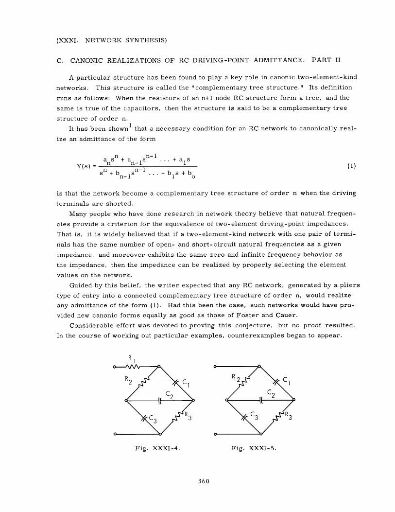
C. CANONIC REALIZATIONS OF RC DRIVING-POINT ADMITTANCE. PART II
A particular structure has been found to play a key role in canonic two-element-kind
networks. This structure is called the "complementary tree structure." Its definition
runs as follows: When the resistors of an n+1 node RC structure form a tree, and the
same is true of the capacitors, then the structure is said to be a complementary tree
structure of order n.
It has been shown1 that a necessary condition for an RC network to canonically real-
ize an admittance of the form
ans + an-1s .+ alsY(s) = n n-1 (1)
s + b n-s .. +bs + bn-i 1 o
is that the network become a complementary tree structure of order n when the driving
terminals are shorted.
Many people who have done research in network theory believe that natural frequen-
cies provide a criterion for the equivalence of two-element driving-point impedances.
That is, it is widely believed that if a two-element-kind network with one pair of termi-
nals has the same number of open- and short-circuit natural frequencies as a given
impedance, and moreover exhibits the same zero and infinite frequency behavior as
the impedance, then the impedance can be realized by properly selecting the element
values on the network.
Guided by this belief, the writer expected that any RC network, generated by a pliers
type of entry into a connected complementary tree structure of order n, would realize
any admittance of the form (1). Had this been the case, such networks would have pro-
vided new canonic forms equally as good as those of Foster and Cauer.
Considerable effort was devoted to proving this conjecture, but no proof resulted.
In the course of working out particular examples, counterexamples began to appear.
R
1
SC2 IC 2
Fig. XXXI-4. Fig. XXXI-5.
360

(XXXI. NETWORK SYNTHESIS)
The simplest counterexample was provided by the network of Fig. XXXI-4. According
to the natural-frequency line of reasoning, this network should be able to realize any RC
admittance of the form
3 2s + a2s + als 1
Y(s)= 2 2 (2)s3 + b 2 s + b 1s + b bs b's+b
3 2s + a2 s + als
For this to be the case, the right-hand member of (2) shows that R 1 must equal 1 ohm,
and the network of Fig. XXXI-5 must be capable of realizing any RC admittance of the
form
3 2s +a 2 s + als
Y'(s) = 2 (3)b's + b'ls +b'
It is shown in the appendix that the network of Fig. XXXI-5 cannot realize all admit-
tances of the form (3), however. Thus, the network of Fig. XXXI-4 does not realize
all admittances of the form (2).
The network of Fig. XXXI-4 fails to do all of the things predicted by natural-
frequency reasoning. The writer has found it convenient to call such networks "bad"
networks." Similarly, it has been found convenient to call networks that live up to
natural-frequency predictions "good networks."
The purpose of this report is to show that a complementary tree structure must have
a definite series-parallel flavor if the pliers type of entry into it is to produce "good"
networks. Before plunging into details it is necessary to agree on notation.
Single resistors and capacitors will be denoted by small r's and c's. Each resis-
tor r of a complementary tree structure is a link of a capacitor tree, and as such pos-
sesses a single capacity path between its terminals; a capital C will be used to indicate
both this path, and the value of its terminal capacity. Similarly, each capacitance of
a complementary tree structure possesses a single resistive path between its terminals
provided by the resistive tree; a capital R will be used to indicate both this path, and
the value of its terminal resistance.
We begin by proving two preliminary theorems.
THEOREM I. If smax and smin are, magnitudewise, the largest and smallest natu-
ral frequencies of a complementary tree structure, and r is a resistor of the structure,
having associated a capacitive path C, then
Is max > i>s min .rC
361

(XXXI. NETWORK SYNTHESIS)
HIGH-FREQUENCYASYMPTOTE WITHSLOPE = C
Y (a)
<71
Fig. XXXI-6.
Fig. XXXI- 7.
PROOF. Let Y denote the admittance into which r looks. The cr-axis plot of Y
has the behavior shown in Fig. XXXI-6. The zero at s = 0 is due to the fact that r can-
not look into a resistive path (if r did look into a resistive path, the over-all structure
would contain a resistive tie set, and thus would contradict the hypothesis that the resis-
tors form a tree). The pole at s = oo is due to the capacitive path C, and for this reason
the high-frequency asymptote has slope equal to C. The dotted line in Fig. XXXI-6 is
the parallel to the high-frequency asymptote which passes through the origin. The natu-
ral frequencies of the structure are given by the intersection between the Y vs cr curve1
and the line Y - r, as shown in Fig. XXXI-7. From the familiar properties of the
Y vs cr curve, it is clear that
SI1 himax rC mi n
so that
5s > 1 > Ismax rC mm Q. E. D.
362
(XXXI. NETWORK SYNTHESIS)
THEOREM II. This is the complement of Theorem I. It may be stated: If, magni-
tudewise, s and s are the maximum and minimum natural frequencies of a com-
plementary tree structure, and c is a capacitor of the structure, having associated a
resistive path R, then
maxI Rc > ISmin
The proof of this theorem is omitted since it is merely the complement of the proof to
Theorem I.
In the rest of this report we shall assume that all RC networks that are considered
have been frequency-scaled so that s min becomes equal to 1 radian per second. If
the ratio Ismax/smin for an unscaled network is denoted by p, Theorems I and II for
the corresponding scaled network read
1SrC > 1 (4)
and
1p > 1, (5)Rc
where r, R, c, and C refer to the element values on the scaled network. And, in partic-
ular, from (4),
r > (6)pC
and from (5),
1> R. (7)c
The key theorem follows.
THEOREM III. Let N be a frequency-scaled complementary tree structure pos-
sessing n capacitors and n resistors that have fixed positive values. If all tie sets ofs
N contain at least three branches, then p > 4. (This theorem implies that max > 4min
for the corresponding unscaled network.)
PROOF. Select any resistor from N and let this be denoted rl. Let C be the1 1
capacity path associated with r and assume that C contains ncl branches. Since, by1 1
hypothesis, the tie set consisting of r and C contains at least three branches, it fol-
lows that ncl >2.
From (6), it is clear that
1 1r > - 1 (8)
pC
363

(XXXI. NETWORK SYNTHESIS)
If cl denotes the largest capacity in C 1 , then cl and C1 satisfy the inequality
1 11 1
nclC c
or
1 ncl1 1 (9)
C c
since the minimum elastance in C1 cannot exceed the average elastance in C I . Substi-
tution of (9) in (8) gives
1 nclr .
1P (10)pc
1this tie set must contain at least three branches, the number of resistors in R n R1
must satisfy nRl > 2. Also, from (7),
1 > R (11)c
If r 2 denotes the smallest resistor in R 1 , then
1R 2ar
nR1
or
1 2R 1 nRlr (12)
since the smallest resistance in R 1 does not exceed the average resistance in R 1 . Sub-
stitution of (12) in (11) gives
1 21 n Rlr
c
or
ncl nclnR1 21 > r . (13)PC Ppc
Let us review the cycle that has just been carried out. A resistor r 1 was selected from
the network at random. The choice of rl singled out a capacitor c 1 (the largest capaci-
tor in C1). The capacitor c l , in turn, singled out a resistor r 2 (the smallest resistor
in R 1). It has been shown that the following relations among rl, ncl, c , nR1 hold
1 >nC1r > 1
pc
364

(XXXI. NETWORK SYNTHESIS)
and
ncl nc InR1> r .
1 ppc
2 2We can now repeat this cycle, starting with r 2 . When this is done, r singles out a
2 3 2 2capacitor c , which, in turn, singles out a resistor r . The quantities r , nc2, c ,nRc'
and r 3 will satisfy the relations
2 nc2r > 2pc
nc2 nc2nRZ 3> P r.2 ppc
23It might happen that some of the physical elements denoted by the symbols r , r , and
c are also denoted by the symbols r1 and c ; however, this need not be the case.
If this cycle is repeated until it has been carried out n times, one obtains the fol-
lowing set of inequalities
cycle 1 l >clpc
n cl>
pc
cycle 2 ir 2
(la)
(Ib)nclnR1 2rP
nc22pc
nc22>
pc
nc2nR2 3r
nrn > cnn
pccycle n
ncn cn nRn n+1n P
Because there are only n different resistors in the network, whereas reference is
made to these by n+1 distinct r in the set of inequalities above, reference must be
made to the same physical resistor by at least two distinct r in the inequalities.
If it happens that rl and r 2 refer to the same physical resistor, substitution of (ib) in
(la) shows that
365
(na)
(nb)
(2b)

(XXXI. NETWORK SYNTHESIS)
i nclnRI 2r > rP
or
1 > ncl nRP
from which it follows that
p > ncl nR1 >4.
If, on the other hand, rl and ri refer to the same physical element, then the substitution
(j-1, b) - (j-l, a) - (j-2, b) - (j-2, a) . . . (ib)- (la)
gives
1 nclnR1 nc2nR2 nc, j-lnR, j-1r > - r
P P P
or
S> ncnR1 nc2nR2 nc,j-1 nR,j-1
P P P
which implies
1
p [(nc1nR1)... (nc, jl-nR, j-1)] j - > 4. (14)
If no other r i denotes the same physical resistor as rl, but rather r a and r b denote the
same resistor, where a < b, then the set of n cycles may be repeated by taking ra as
the initial resistor instead of rl. After this has been done, inequality (14) again applies.
Thus, the inequality p > 4 holds in any case. Q.E. D.
Note: The point may be raised that the proof of Theorem III does not carry through at
face value if several elements on a capacitive or resistive path have numerically
equal values. A review of the proof, however, will show that it still holds if an
arbitrary choice is made between numerically equal elements that qualify as being
the smallest elements on a resistive or elastive path.
Theorem III shows that any particular selection of positive real numbers for the ele-
ment values on a complementary tree structure of the type described leads to the result
smax
>in4.min
366

(XXXI. NETWORK SYNTHESIS)
Thus, it is impossible to find a set of positive real values for the elements of such a
network, so as to obtain
Smax < 4.s min
An important consequence of Theorem III is the following theorem.
THEOREM IV. If the pliers type of entries to a complementary tree structure N
are to produce "good" networks, then N must contain the tie set of Fig. XXXI-8.
PROOF. To be good, N must be able to realize all distinct sets of n natural fre-
quencies, which lie on the negative if-axis of the s-plane. According to Theorem III,
N must have at least one two-branch tie set for this to be possible. Since two-branch
tie sets consisting of two resistors or two capacitors are prohibited, the contained tie
set must have the form shown in Fig. XXXI-8.
Sr Fig. XXXI-8.
The complementary tree structures for which the pliers type of entries lead to "good"
networks, will now be pinned down further. To accomplish this, we assume that
(a) N is a complementary tree structure containing a tie set of the form of
Fig. XXXI-8, and
(b) N' is the network obtained by shorting out the tie set (Fig. XXXI-8),
and prove the following theorems concerning N and N'.
THEOREM V. N' is a complementary tree structure.
PROOF. The proof of this theorem consists of noticing that
(a) The r's and c's and N each form a tree, and
(b) When a branch of a tree t on a network is shorted, the remaining branches of t
form a tree on the simpler network that results.
THEOREM VI. The ratio Ismax/smin is greater for N than it is for N'.
PROOF. Let Y denote the admittance into which the tie set (Fig. XXXI-8) looks.
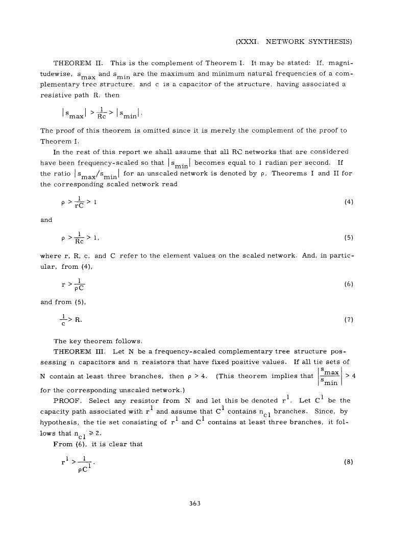
The a-axis behavior of Y will be as shown in Fig. XXXI-9. The zero at s = 0 is due
to the fact that the tie set (Fig. XXXI-8) cannot look into a resistive path (the tie set
cannot look into a resistive path because if it did, then the path and r would form a
resistive loop which is not allowed). The constant behavior at s = oo is due to the fact
that the tie set (Fig. XXXI-8) does not look into a capacitive path. The extreme finite
367
Y(a)
Smin
max
Fig. XXXI-9.
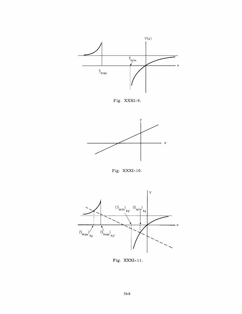
y
Fig. XXXI-10.
Y
(Smin) N (Smi N
II
maxN max N'
Fig. XXXI-11.
368

(XXXI. NETWORK SYNTHESIS)
poles of Y correspond to Smax and smin for N'. The admittance y of the tie set (13)
will have the r-axis behavior shown in Fig. XXXI-10. The natural frequencies of N
will occur when Y = -y as shown in Fig. XXXI-11. Clearly,
I max > Imax N'
and
minN < I Smin N'
so that
s smax > max
minm min N'
Q. E. D.
THEOREM VII. A necessary condition for N to realize all sets of n distinct nega-
tive real natural frequencies is that the topology of N' must impose no lower bound, in
excess of 1, on the ratio
s max
min N'
PROOF. If the topology of N' did impose a lower bound -y, in excess of 1, upon
max
Smin N'
then by Theorem VI, max would also possess -y as a lower bound, and N would5 min N
be unable to realize frequency sets having y > max > 1. Thus if N is to realize allS i
maxinpossible frequency sets, no lower bound on can exist.
min N'
With the help of these theorems, we can now proceed to the main result of this report.
If the pliers type of entries to the complementary tree structure N are to produce "good"
networks, then N certainly must be able to realize all sets of n distinct negative real
natural frequencies. Theorem IV shows that N must contain a tie set of the form of
Fig. XXXI-8 for this to be possible. Theorem VII shows that if this tie set is shorted,
Ismax/smini on the resulting network N' must be free of ratio problems. Theorems IV
and VII show that this will be the case only if
(a) N' possesses a tie set of the form of Fig. XXXI-8, and one finds that
369

(XXXI. NETWORK SYNTHESIS)
(b) Is max/smin on the network N" obtained by shorting this tie set is free of ratio
problems.
By continuing in this manner it becomes clear that the pliers type of entries to N
can yield "good" networks only if N can be reduced to a network of the form of
Fig. XXXI-8 by successively shorting out subnetworks of this form.
This result implies that all complementary tree structures that lead to "good" net-
works are obtainable by the reverse of the reduction above. That is, any structure
leading to a "good" network can be obtained by breaking a short circuit on the network
(Fig. XXXI-8), inserting a network of this form, repeating the procedure on the
resulting network, etc. This is the series-parallel flavor, mentioned earlier, which
complementary tree structures must have if the pliers type of entries into them are to
produce "good" networks.
It remains to be seen whether the structures generated by reversing this reduction,
always yield "good" networks at the pliers type of entry.
APPENDIX
To show that the network of Fig. XXXI-5 cannot realize all admittances of the form
(3), it suffices to show that there is one RC admittance of the form (3) which it cannot
realize. Such an admittance is
s(s+2)(s+4)Y=o (s+l)(s+3)
From physical considerations, it is clear that the network degenerates to the series
combination of cl, c 2 , and c3 at high frequencies. If the capacitance of this path is tobe I farad, as required by Y , then each of the capacitors cl, c 2 , and c 3 must have
capacitance in excess of 1 farad, and their parallel connection must have capacitance
in excess of 3 farads. Since the parallel connection of cl, c 2, and c 3 acc9unts for the
low-frequency behavior at the indicated terminal pair, this means that the low-frequency
capacitance of the network cannot be made as small as that required by Yo (8/3 farads).
Therefore the network cannot realize Y .
It might be thought that Yo could be realized by allowing the elements of
Fig. XXXI-5 to assume negative values. It can be shown, however, that this is
not the case.
H. B. Lee, Jr.
References
1. H. B. Lee, Canonic realizations of RC driving-point admittances, QuarterlyProgress Report No. 62, Research Laboratory of Electronics, M. I. T., July 15, 1961,pp. 287-290.
370