Embed Size (px)
Citation preview
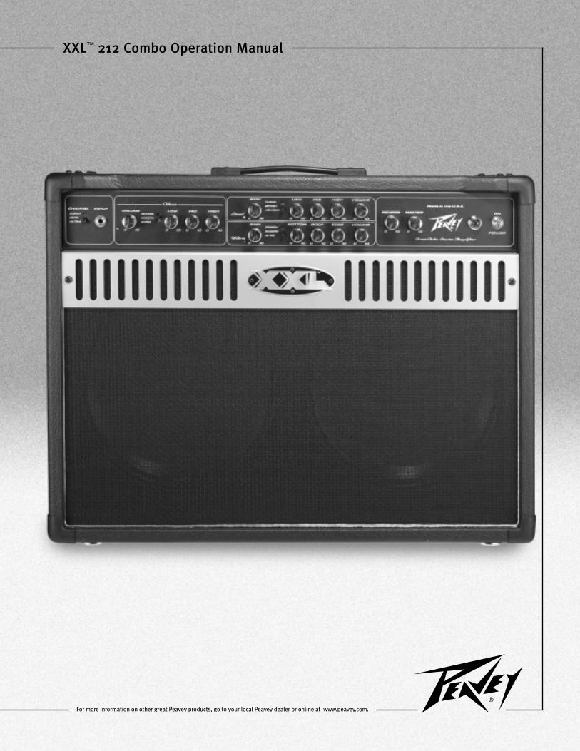
XXL™ 212 Combo Operation Manual
For more information on other great Peavey products, go to your local Peavey dealer or online at www.peavey.com.
2
Intended to alert the user to the presence of uninsulated “dangerous voltage” within the product’s
enclosure that may be of sufficient magnitude to constitute a risk of electric shock to persons.
Intended to alert the user of the presence of important operating and maintenance (servicing)
instructions in the literature accompanying the product.
CCAAUUTTIIOONN:: Risk of electrical shock — DO NOT OPEN!
CCAAUUTTIIOONN:: To reduce the risk of electric shock, do not remove cover. No user serviceable parts inside.
Refer servicing to qualified service personnel.
WWAARRNNIINNGG:: To prevent electrical shock or fire hazard, do not expose this appliance to rain or moisture.
Before using this appliance, read the operating guide for further warnings.
Este símbolo tiene el propósito, de alertar al usuario de la presencia de “(voltaje) peligroso” sin
aislamiento dentro de la caja del producto y que puede tener una magnitud suficiente como para
constituir riesgo de descarga eléctrica.
Este símbolo tiene el propósito de alertar al usario de la presencia de instruccones importantes sobre la
operación y mantenimiento en la información que viene con el producto.
PPRREECCAAUUCCIIOONN:: Riesgo de descarga eléctrica ¡NO ABRIR!
PPRREECCAAUUCCIIOONN:: Para disminuír el riesgo de descarga eléctrica, no abra la cubierta. No hay piezas útiles
dentro. Deje todo mantenimiento en manos del personal técnico cualificado.
AADDVVEERRTTEENNCCIIAA:: Para evitar descargas eléctricas o peligro de incendio, no deje expuesto a la lluvia o
humedad este aparato Antes de usar este aparato, Iea más advertencias en la guía de operación.
Ce symbole est utilisé dans ce manuel pour indiquer à l’utilisateur la présence d’une tension dangereuse
pouvant être d’amplitude suffisante pour constituer un risque de choc électrique.
Ce symbole est utilisé dans ce manuel pour indiquer à l’utilisateur qu’il ou qu’elle trouvera d’importantes
instructions concernant l’utilisation et l’entretien de l’appareil dans le paragraphe signalé.
AATTTTEENNTTIIOONN:: Risques de choc électrique — NE PAS OUVRIR!
AATTTTEENNTTIIOONN:: Afin de réduire le risque de choc électrique, ne pas enlever le couvercle. Il ne se trouve à
l’intérieur aucune pièce pouvant être reparée par l’utilisateur. Confiez I’entretien et la réparation de
l’appareil à un réparateur Peavey agréé.
AAVVEERRTTIISSSSEEMMEENNTT: Afin de prévenir les risques de décharge électrique ou de feu, n’exposez pas cet
appareil à la pluie ou à l’humidité. Avant d’utiliser cet appareil, lisez attentivement les avertissements
supplémentaires de ce manuel.
Dieses Symbol soll den Anwender vor unisolierten gefährlichen Spannungen innerhalb des Gehäuses
warnen, die von Ausreichender Stärke sind, um einen elektrischen Schlag verursachen zu können.
Dieses Symbol soll den Benutzer auf wichtige Instruktionen in der Bedienungsanleitung aufmerksam
machen, die Handhabung und Wartung des Produkts betreffen.
VVOORRSSIICCHHTT:: Risiko — Elektrischer Schlag! Nicht öffnen!
VVOORRSSIICCHHTT:: Um das Risiko eines elektrischen Schlages zu vermeiden, nicht die Abdeckung enfernen. Es
befinden sich keine Teile darin, die vom Anwender repariert werden könnten. Reparaturen nur von
qualifiziertem Fachpersonal durchführen lassen.
AACCHHTTUUNNGG:: Um einen elektrischen Schlag oder Feuergefahr zu vermeiden, sollte dieses Gerät nicht dem
Regen oder Feuchtigkeit ausgesetzt werden. Vor Inbetriebnahme unbedingt die Bedienungsanleitung lesen.
3
IIMMPPOORRTTAANNTT SSAAFFEETTYY IINNSSTTRRUUCCTTIIOONNSS
WWAARRNNIINNGG:: When using electrical products, basic cautions should always be followed, including the following:
1. Read these instructions.
2. Keep these instructions.
3. Heed all warnings.
4. Follow all instructions.
5. Do not use this apparatus near water.
6. Clean only with a dry cloth.
7. Do not block any of the ventilation openings. Install in accordance with manufacturer’s instructions.
8. Do not install near any heat sources such as radiators, heat registers, stoves or other apparatus (including amplifiers)
that produce heat.
9. Do not defeat the safety purpose of the polarized or grounding-type plug. A polarized plug has two blades with one
wider than the other. A grounding type plug has two blades and a third grounding plug. The wide blade or third prong is
provided for your safety. If the provided plug does not fit into your outlet, consult an electrician for replacement of the
obsolete outlet.
10. Protect the power cord from being walked on or pinched, particularly at plugs, convenience receptacles, and the point
they exit from the apparatus.
11. Note for UK only: If the colors of the wires in the mains lead of this unit do not correspond with the terminals in your
plug‚ proceed as follows:
a) The wire that is colored green and yellow must be connected to the terminal that is marked by the letter E‚ the earth
symbol‚ colored green or colored green and yellow.
b) The wire that is colored blue must be connected to the terminal that is marked with the letter N or the color black.
c) The wire that is colored brown must be connected to the terminal that is marked with the letter L or the color red.
12. Only use attachments/accessories provided by the manufacturer.
13. Use only with a cart, stand, tripod, bracket, or table specified by the manufacturer, or sold with the apparatus. When a
cart is used, use caution when moving the cart/apparatus combination to avoid injury from tip-over.
14. Unplug this apparatus during lightning storms or when unused for long periods of time.
15. Refer all servicing to qualified service personnel. Servicing is required when the apparatus has been damaged in any
way, such as power-supply cord or plug is damaged, liquid has been spilled or objects have fallen into the apparatus,
the apparatus has been exposed to rain or moisture, does not operate normally, or has been dropped.
16. Never break off the ground pin. Write for our free booklet “Shock Hazard and Grounding.” Connect only to a power
supply of the type marked on the unit adjacent to the power supply cord.
17. If this product is to be mounted in an equipment rack, rear support should be provided.
18. Exposure to extremely high noise levels may cause a permanent hearing loss. Individuals vary considerably in suscep-
tibility to noise-induced hearing loss, but nearly everyone will lose some hearing if exposed to sufficiently intense noise
for a sufficient time. The U.S. Government’s Occupational Safety and Health Administration (OSHA) has specified the
following permissible noise level exposures:
Duration Per Day In Hours Sound Level dBA, Slow Response
8 90
6 92
4 95
3 97
2 100
1 1⁄2 102
1 1051⁄2 110
1⁄4 or less 115
According to OSHA, any exposure in excess of the above permissible limits could result in some hearing loss. Ear plugs or protectors to the
ear canals or over the ears must be worn when operating this amplification system in order to prevent a permanent hearing loss, if exposure
is in excess of the limits as set forth above. To ensure against potentially dangerous exposure to high sound pressure levels, it is
recommended that all persons exposed to equipment capable of producing high sound pressure levels such as this amplification system be
protected by hearing protectors while this unit is in operation.
SSAAVVEE TTHHEESSEE IINNSSTTRRUUCCTTIIOONNSS!!
4
Big features….big sound. The XXL™ 212 COMBO is the culmination of nearly a decade of refinements and tweaks to Peavey’s
innovative TransTube® vacuum tube emulation circuitry. The result is a monster of an amplifier capable of accurately
reproducing tons and tons of the hottest tube amp tones imaginable….past and present. Three fully independent channels
(clean/passive EQ, lead/passive EQ, and ultra/active EQ) give you a sonic palette that lets your imagination run wild. From the
sparkling clean tones of the “vintage” mode to the nearly uncontrollable scream of the “ultra” mode to the extreme flexibility
of new TransTube power amp damping and power level switches, the XXL 212 COMBO is sure to leave you mesmerized every
time you plug in. Capable of over 100 Watts of earth shaking power into its two 12" Blue Marvel speakers (or any standard
guitar cabinet), this behemoth can blow the roof off the largest of venues or….with a twist of the master volume and a flip of
the 25/50/100 Watt power level switch, keep a crowd in the smallest of settings. Further tonal mayhem can be accomplished
with outboard effects via the footswitchable effects loop. Reverb is also included to put the icing on the cake. We’ve even
thrown in a free heavy-duty metal footswitch and a classic jeweled pilot light so that you will certainly have the tools to break
ALL of the rules. The all new Peavey XXL 212 COMBO….now you don’t have anymore excuses.
FFEEAATTUURREESS::
• Two 12" Blue Marvel Speakers
• Three‚ fully independent channels
• Bottom, body, and edge active EQ on ultra channel
• Three-band passive EQ on clean and lead channels
• Three-position EQ and gain voicing switches on each channel
• 100 W (RMS) into 4, 8, or 16 Ohms (selectable impedance)
• Power level switch for 25 W, 50 W, or 100 W operation
• Power amp damping switch (tight, medium, loose)
• Footswitchable effects loop with effects level switch
• Preamp out/power amp In patching jacks
• Reverb
• Master volume
• Three-button‚ metal footswitch with 25' detachable cable (included)
• Classic jeweled pilot light
• Chrome-plated brass control knobs
EENNGGLLIISSHH
5
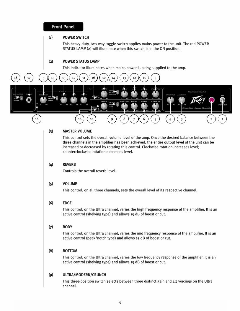
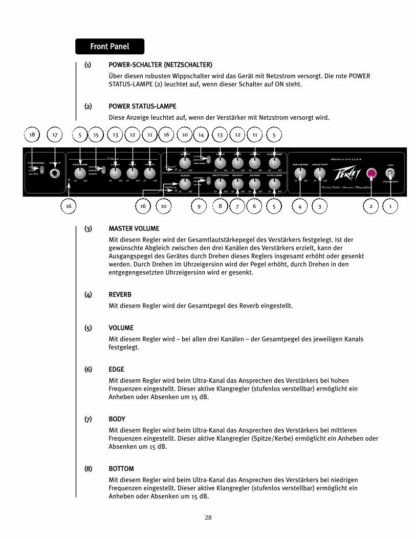
((11)) PPOOWWEERR SSWWIITTCCHH
This heavy-duty, two-way toggle switch applies mains power to the unit. The red POWER
STATUS LAMP (2) will illuminate when this switch is in the ON position.
((22)) PPOOWWEERR SSTTAATTUUSS LLAAMMPP
This indicator illuminates when mains power is being supplied to the amp.
((33)) MMAASSTTEERR VVOOLLUUMMEE
This control sets the overall volume level of the amp. Once the desired balance between the
three channels in the amplifier has been achieved, the entire output level of the unit can be
increased or decreased by rotating this control. Clockwise rotation increases level;
counterclockwise rotation decreases level.
((44)) RREEVVEERRBB
Controls the overall reverb level.
((55)) VVOOLLUUMMEE
This control, on all three channels, sets the overall level of its respective channel.
((66)) EEDDGGEE
This control, on the Ultra channel, varies the high frequency response of the amplifier. It is an
active control (shelving type) and allows 15 dB of boost or cut.
((77)) BBOODDYY
This control, on the Ultra channel, varies the mid frequency response of the amplifier. It is an
active control (peak/notch type) and allows 15 dB of boost or cut.
((88)) BBOOTTTTOOMM
This control, on the Ultra channel, varies the low frequency response of the amplifier. It is an
active control (shelving type) and allows 15 dB of boost or cut.
((99)) UULLTTRRAA//MMOODDEERRNN//CCRRUUNNCCHH
This three-position switch selects between three distinct gain and EQ voicings on the Ultra
channel.
1234567816
FFrroonntt PPaanneell
9
510 14161518 1112131213 11517
1016
6
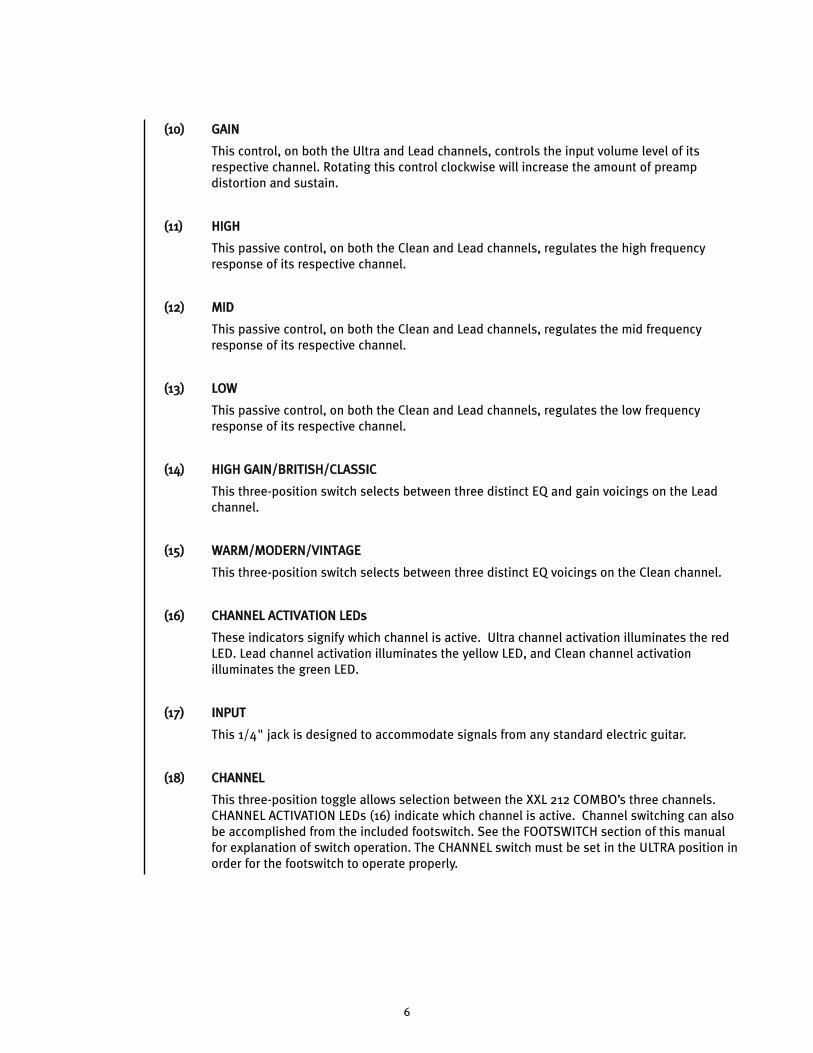
((1100)) GGAAIINN
This control, on both the Ultra and Lead channels, controls the input volume level of its
respective channel. Rotating this control clockwise will increase the amount of preamp
distortion and sustain.
((1111)) HHIIGGHH
This passive control, on both the Clean and Lead channels, regulates the high frequency
response of its respective channel.
((1122)) MMIIDD
This passive control, on both the Clean and Lead channels, regulates the mid frequency
response of its respective channel.
((1133)) LLOOWW
This passive control, on both the Clean and Lead channels, regulates the low frequency
response of its respective channel.
((1144)) HHIIGGHH GGAAIINN//BBRRIITTIISSHH//CCLLAASSSSIICC
This three-position switch selects between three distinct EQ and gain voicings on the Lead
channel.
((1155)) WWAARRMM//MMOODDEERRNN//VVIINNTTAAGGEE
This three-position switch selects between three distinct EQ voicings on the Clean channel.
((1166)) CCHHAANNNNEELL AACCTTIIVVAATTIIOONN LLEEDDss
These indicators signify which channel is active. Ultra channel activation illuminates the red
LED. Lead channel activation illuminates the yellow LED, and Clean channel activation
illuminates the green LED.
((1177)) IINNPPUUTT
This 1/4" jack is designed to accommodate signals from any standard electric guitar.
((1188)) CCHHAANNNNEELL
This three-position toggle allows selection between the XXL 212 COMBO’s three channels.
CHANNEL ACTIVATION LEDs (16) indicate which channel is active. Channel switching can also
be accomplished from the included footswitch. See the FOOTSWITCH section of this manual
for explanation of switch operation. The CHANNEL switch must be set in the ULTRA position in
order for the footswitch to operate properly.
7
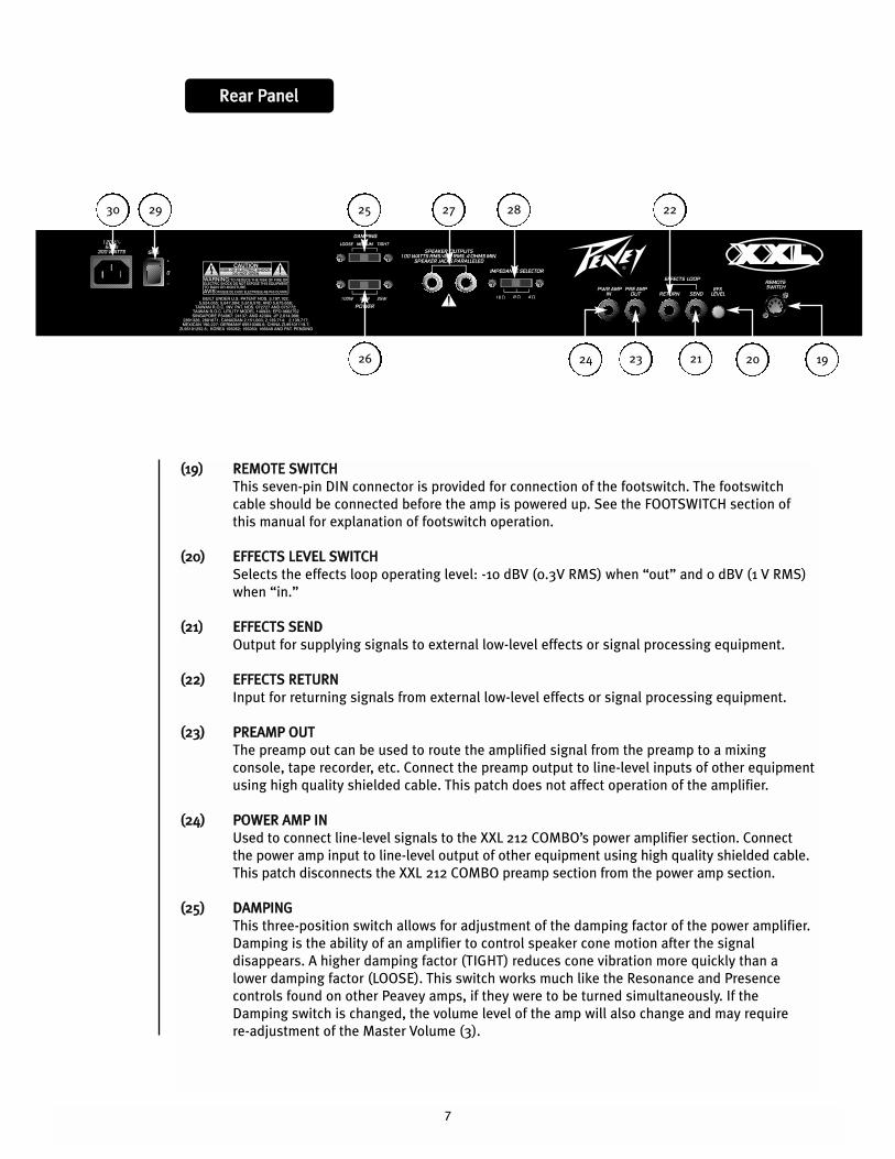
((1199)) RREEMMOOTTEE SSWWIITTCCHH
This seven-pin DIN connector is provided for connection of the footswitch. The footswitch
cable should be connected before the amp is powered up. See the FOOTSWITCH section of
this manual for explanation of footswitch operation.
((2200)) EEFFFFEECCTTSS LLEEVVEELL SSWWIITTCCHH
Selects the effects loop operating level: -10 dBV (0.3V RMS) when “out” and 0 dBV (1 V RMS)
when “in.”
((2211)) EEFFFFEECCTTSS SSEENNDD
Output for supplying signals to external low-level effects or signal processing equipment.
((2222)) EEFFFFEECCTTSS RREETTUURRNN
Input for returning signals from external low-level effects or signal processing equipment.
((2233)) PPRREEAAMMPP OOUUTT
The preamp out can be used to route the amplified signal from the preamp to a mixing
console, tape recorder, etc. Connect the preamp output to line-level inputs of other equipment
using high quality shielded cable. This patch does not affect operation of the amplifier.
((2244)) PPOOWWEERR AAMMPP IINN
Used to connect line-level signals to the XXL 212 COMBO’s power amplifier section. Connect
the power amp input to line-level output of other equipment using high quality shielded cable.
This patch disconnects the XXL 212 COMBO preamp section from the power amp section.
((2255)) DDAAMMPPIINNGG
This three-position switch allows for adjustment of the damping factor of the power amplifier.
Damping is the ability of an amplifier to control speaker cone motion after the signal
disappears. A higher damping factor (TIGHT) reduces cone vibration more quickly than a
lower damping factor (LOOSE). This switch works much like the Resonance and Presence
controls found on other Peavey amps, if they were to be turned simultaneously. If the
Damping switch is changed, the volume level of the amp will also change and may require
re-adjustment of the Master Volume (3).
RReeaarr PPaanneell
212326
22252930
192024
27 28
8
((2266)) PPOOWWEERR
This three-position switch selects the power output level of the power amplifier. This switch
works like the T. Dynamics® control found on other Peavey amplifiers which provides for a
more pronounced tube power compression simulation at lower settings.
((2277)) SSPPEEAAKKEERR OOUUTTPPUUTTSS
These paralleled 1⁄4" mono (TS) jacks are provided for the connection of speaker enclosure(s).
Minimum speaker impedance is 4 Ohms. The CABINET IMPEDANCE switch (28) must be set to
match the load of the speaker cabinet(s).
((2288)) CCAABBIINNEETT IIMMPPEEDDAANNCCEE
This three-position switch allows for appropriate selection of speaker cabinet impedance. If
two enclosures of equal impedance are used, the switch should be set to half the individual
value. For example, two 16 Ohm enclosures necessitate an 8 Ohm setting, while two 8 Ohm
enclosures would require a 4 Ohm setting. Minimum speaker impedance is 4 Ohms. This
switch should be set to 16 Ohms when no external cabinet is connected.
((2299)) GGRROOUUNNDD PPOOLLAARRIITTYY SSWWIITTCCHH
This three-position rocker switch should normally be placed in the center (0) position. If hum
or noise is noticed coming from the speaker enclosure(s), the switch may be placed in the “+”
or “-” position to minimize hum and noise. If changing the polarity does not alleviate the
problem, consult your authorized Peavey dealer, the Peavey factory, or a qualified service
technician.
((3300)) IIEECC MMAAIINNSS CCOONNNNEECCTTOORR
This is a standard IEC power connector. An AC mains cord having the appropriate AC plug and
ratings for the intended operating voltage is included in the carton. The mains cord should be
connected to the amplifier before connecting to a suitable AC outlet.
9
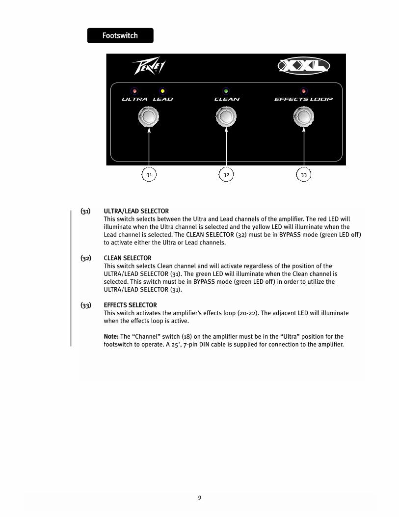
FFoooottsswwiittcchh
((3311)) UULLTTRRAA//LLEEAADD SSEELLEECCTTOORR
This switch selects between the Ultra and Lead channels of the amplifier. The red LED will
illuminate when the Ultra channel is selected and the yellow LED will illuminate when the
Lead channel is selected. The CLEAN SELECTOR (32) must be in BYPASS mode (green LED off )
to activate either the Ultra or Lead channels.
((3322)) CCLLEEAANN SSEELLEECCTTOORR
This switch selects Clean channel and will activate regardless of the position of the
ULTRA/LEAD SELECTOR (31). The green LED will illuminate when the Clean channel is
selected. This switch must be in BYPASS mode (green LED off ) in order to utilize the
ULTRA/LEAD SELECTOR (31).
((3333)) EEFFFFEECCTTSS SSEELLEECCTTOORR
This switch activates the amplifier’s effects loop (20-22). The adjacent LED will illuminate
when the effects loop is active.
NNoottee:: The “Channel” switch (18) on the amplifier must be in the “Ultra” position for the
footswitch to operate. A 25'‚ 7-pin DIN cable is supplied for connection to the amplifier.
31 32 33
10
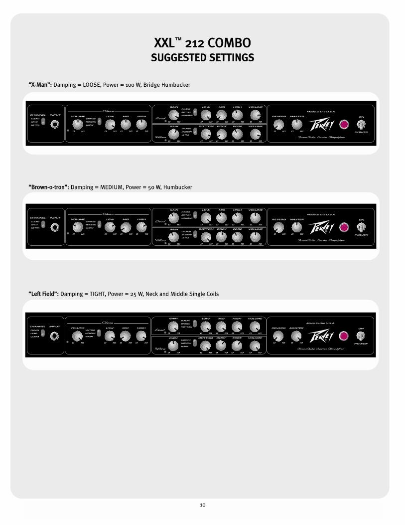
XXXXLL™™ 221122 CCOOMMBBOOSSUUGGGGEESSTTEEDD SSEETTTTIINNGGSS
““XX--MMaann””:: Damping = LOOSE, Power = 100 W, Bridge Humbucker
““BBrroowwnn--oo--ttrroonn””:: Damping = MEDIUM, Power = 50 W, Humbucker
““LLeefftt FFiieelldd””:: Damping = TIGHT, Power = 25 W, Neck and Middle Single Coils
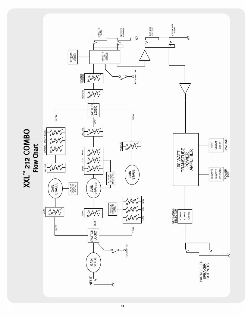
11
XXXX
LL™™
221122
CCOO
MMBB
OOFFll
ooww
CChh
aarrtt
12
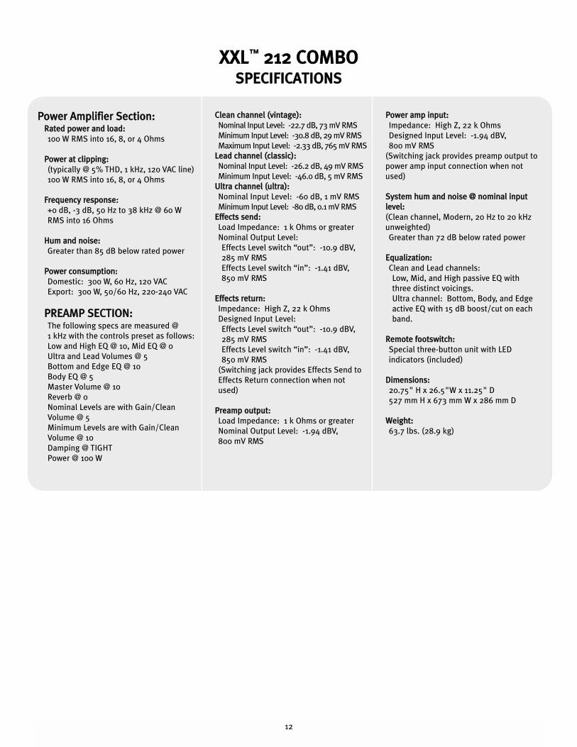
PPoowweerr AAmmpplliiffiieerr SSeeccttiioonn::RRaatteedd ppoowweerr aanndd llooaadd::
100 W RMS into 16, 8, or 4 Ohms
PPoowweerr aatt cclliippppiinngg::
(typically @ 5% THD, 1 kHz, 120 VAC line)
100 W RMS into 16, 8, or 4 Ohms
FFrreeqquueennccyy rreessppoonnssee::
+0 dB, -3 dB, 50 Hz to 38 kHz @ 60 W
RMS into 16 Ohms
HHuumm aanndd nnooiissee::
Greater than 85 dB below rated power
PPoowweerr ccoonnssuummppttiioonn::
Domestic: 300 W, 60 Hz, 120 VAC
Export: 300 W, 50/60 Hz, 220-240 VAC
PPRREEAAMMPP SSEECCTTIIOONN::The following specs are measured @
1 kHz with the controls preset as follows:
Low and High EQ @ 10, Mid EQ @ 0
Ultra and Lead Volumes @ 5
Bottom and Edge EQ @ 10
Body EQ @ 5
Master Volume @ 10
Reverb @ 0
Nominal Levels are with Gain/Clean
Volume @ 5
Minimum Levels are with Gain/Clean
Volume @ 10
Damping @ TIGHT
Power @ 100 W
CClleeaann cchhaannnneell ((vviinnttaaggee))::
Nominal Input Level: -22.7 dB, 73 mV RMS
Minimum Input Level: -30.8 dB, 29 mV RMS
Maximum Input Level: -2.33 dB, 765 mV RMS
LLeeaadd cchhaannnneell ((ccllaassssiicc))::
Nominal Input Level: -26.2 dB, 49 mV RMS
Minimum Input Level: -46.0 dB, 5 mV RMS
UUllttrraa cchhaannnneell ((uullttrraa))::
Nominal Input Level: -60 dB, 1 mV RMS
Minimum Input Level: -80 dB, 0.1 mV RMS
EEffffeeccttss sseenndd::
Load Impedance: 1 k Ohms or greater
Nominal Output Level:
Effects Level switch “out”: -10.9 dBV,
285 mV RMS
Effects Level switch “in”: -1.41 dBV,
850 mV RMS
EEffffeeccttss rreettuurrnn::
Impedance: High Z, 22 k Ohms
Designed Input Level:
Effects Level switch “out”: -10.9 dBV,
285 mV RMS
Effects Level switch “in”: -1.41 dBV,
850 mV RMS
(Switching jack provides Effects Send to
Effects Return connection when not
used)
PPrreeaammpp oouuttppuutt::
Load Impedance: 1 k Ohms or greater
Nominal Output Level: -1.94 dBV,
800 mV RMS
PPoowweerr aammpp iinnppuutt::
Impedance: High Z, 22 k Ohms
Designed Input Level: -1.94 dBV,
800 mV RMS
(Switching jack provides preamp output to
power amp input connection when not
used)
SSyysstteemm hhuumm aanndd nnooiissee @@ nnoommiinnaall iinnppuutt
lleevveell::
(Clean channel, Modern, 20 Hz to 20 kHz
unweighted)
Greater than 72 dB below rated power
EEqquuaalliizzaattiioonn::
Clean and Lead channels:
Low, Mid, and High passive EQ with
three distinct voicings.
Ultra channel: Bottom, Body, and Edge
active EQ with 15 dB boost/cut on each
band.
RReemmoottee ffoooottsswwiittcchh::
Special three-button unit with LED
indicators (included)
DDiimmeennssiioonnss::
20.75" H x 26.5"W x 11.25" D
527 mm H x 673 mm W x 286 mm D
WWeeiigghhtt::
63.7 lbs. (28.9 kg)
XXXXLL™™ 221122 CCOOMMBBOOSSPPEECCIIFFIICCAATTIIOONNSS
13
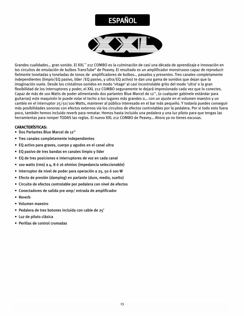
EESSPPAAÑÑOOLL
Grandes cualidades… gran sonido. El XXL™ 212 COMBO es la culminación de casi una década de aprendizaje e innovación en
los circuitos de emulación de bulbos TransTube® de Peavey. El resultado es un amplificador monstruoso capaz de reproducir
fielmente toneladas y toneladas de tonos de amplificadores de bulbos… pasados y presentes. Tres canales completamente
independientes (limpio/EQ pasivo, líder /EQ pasivo, y ultra/EQ activo) te dan una gama de sonidos que dejan que la
imaginación vuele. Desde los cristalinos sonidos en modo ‘vitage’ al casi incontrolable grito del modo ‘ultra’ o la gran
flexibilidad de los interruptores y poder, el XXL 212 COMBO seguramente te dejará impresionado cada vez que lo conectes.
Capaz de más de 100 Watts de poder alimentando dos parlantes Blue Marcel de 12", (o cualquier gabinete estándar para
guitarras) este maquinón le puede volar el techo a los lugares más grandes o… con un ajuste en el volumen maestro y un
cambio en el interruptor 25/50/100 Watts, mantener al público interesado en el bar más pequeño. Y todavía puedes conseguir
más posibilidades sonoras con efectos externos vía los circuitos de efectos controlables por la pedalera. Por si todo esto fuera
poco, también hemos incluido reverb para rematar. Hemos hasta incluido una pedalera y una luz piloto para que tengas las
herramientas para romper TODAS las reglas. El nuevo XXL 212 COMBO de Peavey… Ahora ya no tienes excusas.
CCAARRAACCTTEERRÍÍSSTTIICCAASS::
• Dos Parlantes Blue Marcel de 12"
• Tres canales completamente independientes
• EQ activo para graves, cuerpo y agudos en el canal ultra
• EQ pasivo de tres bandas en canales limpio y líder
• EQ de tres posiciones e interruptores de voz en cada canal
• 100 watts (rms) a 4, 8 ó 16 ohmios (impedancia seleccionable)
• Interruptor de nivel de poder para operación a 25, 50 ó 100 W
• Efecto de presión (damping) en parlante (duro, medio, suelto)
• Circuito de efectos controlable por pedalera con nivel de efectos
• Conectadores de salida pre amp/ entrada de amplificador
• Reverb
• Volumen maestro
• Pedalera de tres botones incluida con cable de 25’
• Luz de piloto clásica
• Perillas de control cromadas
14
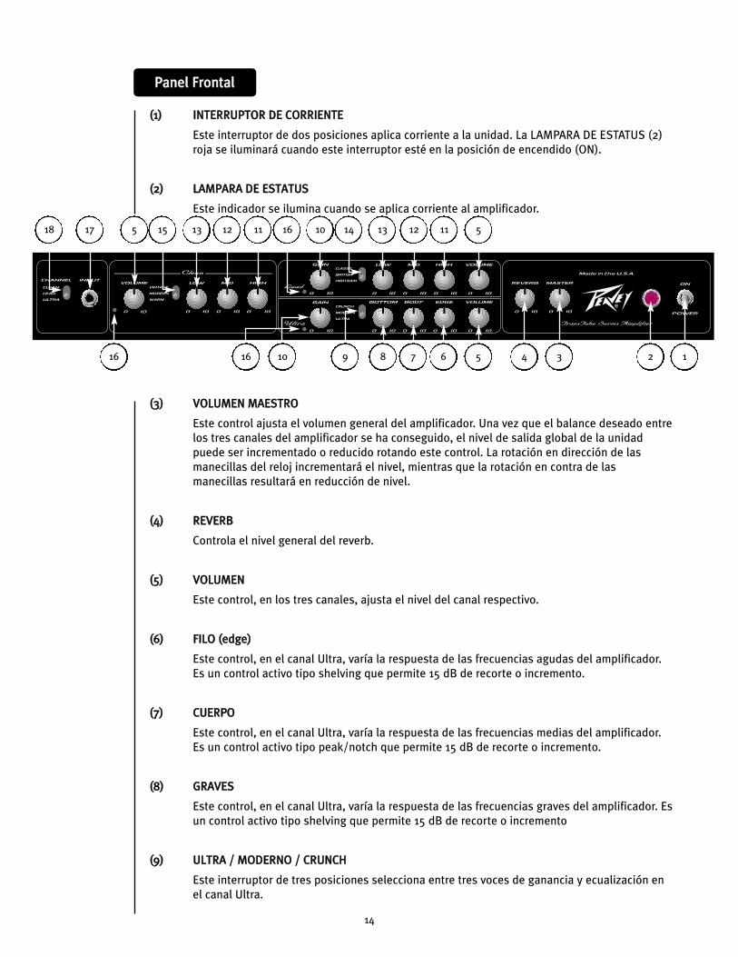
PPaanneell FFrroonnttaall
((11)) IINNTTEERRRRUUPPTTOORR DDEE CCOORRRRIIEENNTTEE
Este interruptor de dos posiciones aplica corriente a la unidad. La LAMPARA DE ESTATUS (2)
roja se iluminará cuando este interruptor esté en la posición de encendido (ON).
((22)) LLAAMMPPAARRAA DDEE EESSTTAATTUUSS
Este indicador se ilumina cuando se aplica corriente al amplificador.
((33)) VVOOLLUUMMEENN MMAAEESSTTRROO
Este control ajusta el volumen general del amplificador. Una vez que el balance deseado entre
los tres canales del amplificador se ha conseguido, el nivel de salida global de la unidad
puede ser incrementado o reducido rotando este control. La rotación en dirección de las
manecillas del reloj incrementará el nivel, mientras que la rotación en contra de las
manecillas resultará en reducción de nivel.
((44)) RREEVVEERRBB
Controla el nivel general del reverb.
((55)) VVOOLLUUMMEENN
Este control, en los tres canales, ajusta el nivel del canal respectivo.
((66)) FFIILLOO ((eeddggee))
Este control, en el canal Ultra, varía la respuesta de las frecuencias agudas del amplificador.
Es un control activo tipo shelving que permite 15 dB de recorte o incremento.
((77)) CCUUEERRPPOO
Este control, en el canal Ultra, varía la respuesta de las frecuencias medias del amplificador.
Es un control activo tipo peak/notch que permite 15 dB de recorte o incremento.
((88)) GGRRAAVVEESS
Este control, en el canal Ultra, varía la respuesta de las frecuencias graves del amplificador. Es
un control activo tipo shelving que permite 15 dB de recorte o incremento
((99)) UULLTTRRAA // MMOODDEERRNNOO // CCRRUUNNCCHH
Este interruptor de tres posiciones selecciona entre tres voces de ganancia y ecualización en
el canal Ultra.
1234567816 9
510 14161518 1112131213 11517
1016
15
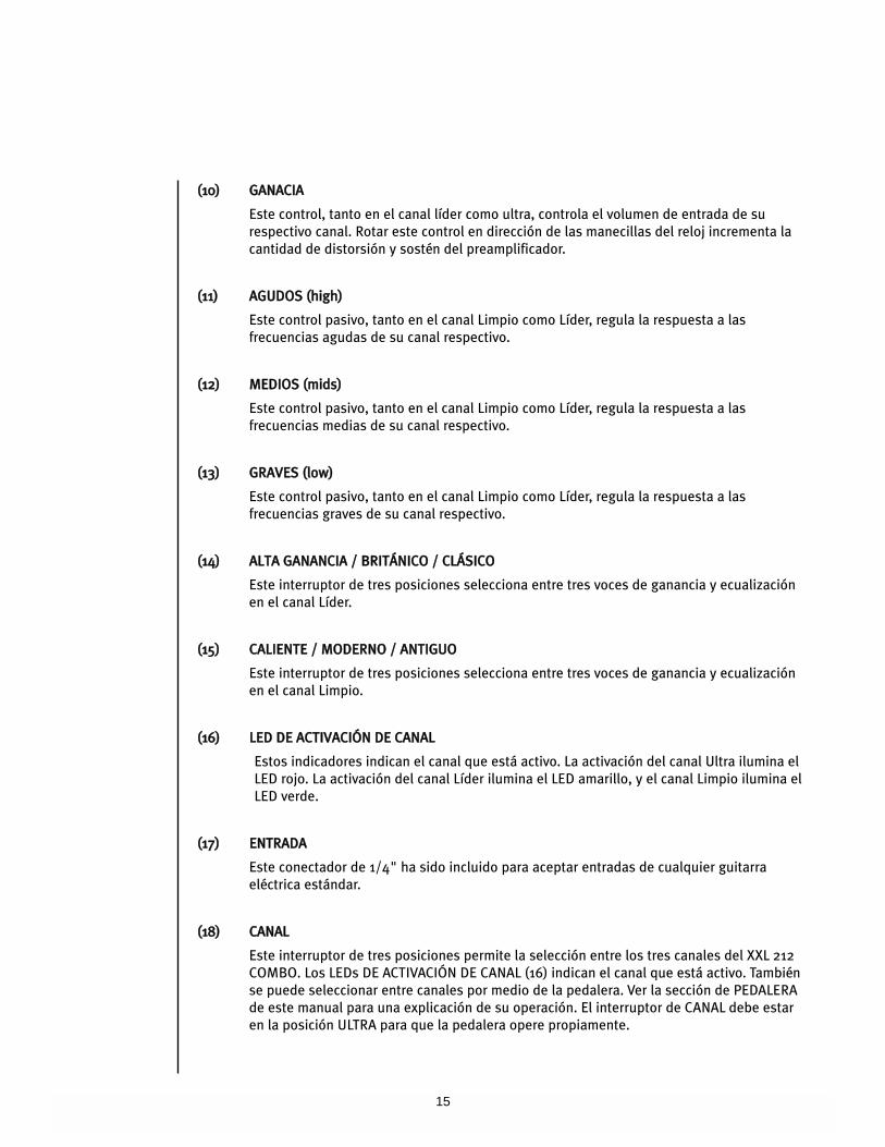
((1100)) GGAANNAACCIIAA
Este control, tanto en el canal líder como ultra, controla el volumen de entrada de su
respectivo canal. Rotar este control en dirección de las manecillas del reloj incrementa la
cantidad de distorsión y sostén del preamplificador.
((1111)) AAGGUUDDOOSS ((hhiigghh))
Este control pasivo, tanto en el canal Limpio como Líder, regula la respuesta a las
frecuencias agudas de su canal respectivo.
((1122)) MMEEDDIIOOSS ((mmiiddss))
Este control pasivo, tanto en el canal Limpio como Líder, regula la respuesta a las
frecuencias medias de su canal respectivo.
((1133)) GGRRAAVVEESS ((llooww))
Este control pasivo, tanto en el canal Limpio como Líder, regula la respuesta a las
frecuencias graves de su canal respectivo.
((1144)) AALLTTAA GGAANNAANNCCIIAA // BBRRIITTÁÁNNIICCOO // CCLLÁÁSSIICCOO
Este interruptor de tres posiciones selecciona entre tres voces de ganancia y ecualización
en el canal Líder.
((1155)) CCAALLIIEENNTTEE // MMOODDEERRNNOO // AANNTTIIGGUUOO
Este interruptor de tres posiciones selecciona entre tres voces de ganancia y ecualización
en el canal Limpio.
((1166)) LLEEDD DDEE AACCTTIIVVAACCIIÓÓNN DDEE CCAANNAALL
Estos indicadores indican el canal que está activo. La activación del canal Ultra ilumina el
LED rojo. La activación del canal Líder ilumina el LED amarillo, y el canal Limpio ilumina el
LED verde.
((1177)) EENNTTRRAADDAA
Este conectador de 1/4" ha sido incluido para aceptar entradas de cualquier guitarra
eléctrica estándar.
((1188)) CCAANNAALL
Este interruptor de tres posiciones permite la selección entre los tres canales del XXL 212
COMBO. Los LEDs DE ACTIVACIÓN DE CANAL (16) indican el canal que está activo. También
se puede seleccionar entre canales por medio de la pedalera. Ver la sección de PEDALERA
de este manual para una explicación de su operación. El interruptor de CANAL debe estar
en la posición ULTRA para que la pedalera opere propiamente.
16
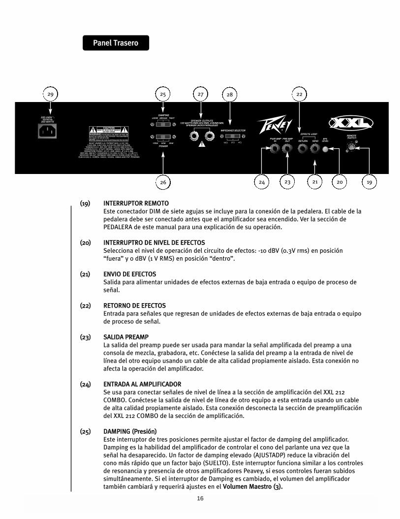
PPaanneell TTrraasseerroo
212326
222529
192024
27 28
((1199)) IINNTTEERRRRUUPPTTOORR RREEMMOOTTOO
Este conectador DIM de siete agujas se incluye para la conexión de la pedalera. El cable de la
pedalera debe ser conectado antes que el amplificador sea encendido. Ver la sección de
PEDALERA de este manual para una explicación de su operación.
((2200)) IINNTTEERRRRUUPPTTRROO DDEE NNIIVVEELL DDEE EEFFEECCTTOOSS
Selecciona el nivel de operación del circuito de efectos: -10 dBV (0.3V rms) en posición
“fuera” y 0 dBV (1 V RMS) en posición “dentro”.
((2211)) EENNVVIIOO DDEE EEFFEECCTTOOSS
Salida para alimentar unidades de efectos externas de baja entrada o equipo de proceso de
señal.
((2222)) RREETTOORRNNOO DDEE EEFFEECCTTOOSS
Entrada para señales que regresan de unidades de efectos externas de baja entrada o equipo
de proceso de señal.
((2233)) SSAALLIIDDAA PPRREEAAMMPP
La salida del preamp puede ser usada para mandar la señal amplificada del preamp a una
consola de mezcla, grabadora, etc. Conéctese la salida del preamp a la entrada de nivel de
línea del otro equipo usando un cable de alta calidad propiamente aislado. Esta conexión no
afecta la operación del amplificador.
((2244)) EENNTTRRAADDAA AALL AAMMPPLLIIFFIICCAADDOORR
Se usa para conectar señales de nivel de línea a la sección de amplificación del XXL 212
COMBO. Conéctese la salida de nivel de línea de otro equipo a esta entrada usando un cable
de alta calidad propiamente aislado. Esta conexión desconecta la sección de preamplificación
del XXL 212 COMBO de la sección de amplificación.
((2255)) DDAAMMPPIINNGG ((PPrreessiióónn))
Este interruptor de tres posiciones permite ajustar el factor de damping del amplificador.
Damping es la habilidad del amplificador de controlar el cono del parlante una vez que la
señal ha desaparecido. Un factor de damping elevado (AJUSTADP) reduce la vibración del
cono más rápido que un factor bajo (SUELTO). Este interruptor funciona similar a los controles
de resonancia y presencia de otros amplificadores Peavey, si esos controles fueran subidos
simultáneamente. Si el interruptor de Damping es cambiado, el volumen del amplificador
también cambiará y requerirá ajustes en el VVoolluummeenn MMaaeessttrroo ((33))..
17
((2266)) PPOODDEERR
Este interruptor de tres posiciones selecciona el nivel de salida del amplificador. Este
interruptor funciona como el control T Dynamics® que se encuentra en amplificadores Peavey
que proveen una simulación de compresión de bulbos más pronunciada a niveles más bajos.
((2277)) SSAALLIIDDAASS DDEE PPAARRLLAANNTTEESS
Estos conectadores de 1/4" no balanceados (TS) se incluyen para la conexión de parlantes. La
impedancia mínima es de 4 Ohmios. El INTERRUPTOR DE IMPEDANCIA DE GABINETE (28)
debe ser ajustado igual que la carga del gabinete de parlantes.
((2288)) IINNTTEERRRRUUPPTTOORR DDEE IIMMPPEEDDAANNCCIIAA DDEE GGAABBIINNEETTEE
Este interruptor de tres posiciones permite la selección apropiada de impedancia de los
diferentes gabinetes. Si se usan dos gabinetes de la misma impedancia, el interruptor debe
ser ajustado a la mitad del valor individual. Por ejemplo, dos gabinetes de 16 ohmios
necesitan un ajuste a la posición de 8 ohmios, mientras que dos gabinetes de 8 ohmios cada
uno requerirán la posición de 4 ohmios. La impedancia mínima es de 4 ohmios. Este
interruptor debe estar en la posición de 16 Ohmios cuando no está conectado un gabinete
externo.
((2299)) CCOONNEECCTTAADDOORR PPRRIINNCCIIPPAALL IIEECC
Este es un conectador estándar IEC. Un cable de CA con los conectores y capacidades para el
voltaje de operación es incluido en el paquete. El cable de corriente debe ser conectado al
amplificador antes de conectarse a la fuente de corriente.
18
FFoooottsswwiittcchh
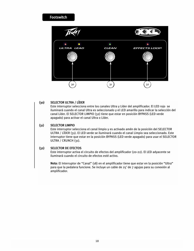
((3300)) SSEELLEECCTTOORR UULLTTRRAA // LLÍÍDDEERR
Este interruptor selecciona entre los canales Ultra y Líder del amplificador. El LED rojo se
iluminará cuando el canal Ultra es seleccionado y el LED amarillo para indicar la selección del
canal Líder. El SELECTOR LIMPIO (32) tiene que estar en posición BYPASS (LED verde
apagado) para activar el canal Ultra o Líder.
((3311)) SSEELLEECCTTOORR LLIIMMPPIIOO
Este interruptor selecciona el canal limpio y es activado amén de la posición del SELECTOR
ULTRA / LÍDER (31). El LED verde se iluminará cuando el canal Limpio sea seleccionado. Este
interruptor tiene que estar en la posición BYPASS (LED verde apagado) para usar el SELECTOR
ULTRA / CRUNCH (31).
((3322)) SSEELLEECCTTOORR DDEE EEFFEECCTTOOSS
Este interruptor activa el circuito de efectos del amplificador (20-22). El LED adyacente se
iluminará cuando el circuito de efectos esté activo.
NNoottaa:: El Interruptor de “Canal” (18) en el amplificador tiene que estar en la posición “Ultra”
para que la pedalera funcione. Se incluye un cable de 25’ de 7 agujas para su conexión al
amplificador.
30 3231
19
PPoowweerr AAmmpplliiffiieerr SSeeccttiioonn::RRaatteedd ppoowweerr aanndd llooaadd::
100 W RMS into 16, 8, or 4 Ohms
PPoowweerr aatt cclliippppiinngg::
(typically @ 5% THD, 1 kHz, 120 VAC line)
100 W RMS into 16, 8, or 4 Ohms
FFrreeqquueennccyy rreessppoonnssee::
+0 dB, -3 dB, 50 Hz to 38 kHz @ 60 W
RMS into 16 Ohms
HHuumm aanndd nnooiissee::
Greater than 85 dB below rated power
PPoowweerr ccoonnssuummppttiioonn::
Domestic: 300 W, 60 Hz, 120 VAC
Export: 300 W, 50/60 Hz, 220-240 VAC
PPRREEAAMMPP SSEECCTTIIOONN::The following specs are measured @
1 kHz with the controls preset as follows:
Low and High EQ @ 10, Mid EQ @ 0
Ultra and Lead Volumes @ 5
Bottom and Edge EQ @ 10
Body EQ @ 5
Master Volume @ 10
Reverb @ 0
Nominal Levels are with Gain/Clean
Volume @ 5
Minimum Levels are with Gain/Clean
Volume @ 10
Damping @ TIGHT
Power @ 100 W
CClleeaann cchhaannnneell ((vviinnttaaggee))::
Nominal Input Level: -22.7 dB, 73 mV RMS
Minimum Input Level: -30.8 dB, 29 mV RMS
Maximum Input Level: -2.33 dB, 765 mV RMS
LLeeaadd cchhaannnneell ((ccllaassssiicc))::
Nominal Input Level: -26.2 dB, 49 mV RMS
Minimum Input Level: -46.0 dB, 5 mV RMS
UUllttrraa cchhaannnneell ((uullttrraa))::
Nominal Input Level: -60 dB, 1 mV RMS
Minimum Input Level: -80 dB, 0.1 mV RMS
EEffffeeccttss sseenndd::
Load Impedance: 1 k Ohms or greater
Nominal Output Level:
Effects Level switch “out”: -10.9 dBV,
285 mV RMS
Effects Level switch “in”: -1.41 dBV,
850 mV RMS
EEffffeeccttss rreettuurrnn::
Impedance: High Z, 22 k Ohms
Designed Input Level:
Effects Level switch “out”: -10.9 dBV,
285 mV RMS
Effects Level switch “in”: -1.41 dBV,
850 mV RMS
(Switching jack provides Effects Send to
Effects Return connection when not
used)
PPrreeaammpp oouuttppuutt::
Load Impedance: 1 k Ohms or greater
Nominal Output Level: -1.94 dBV,
800 mV RMS
PPoowweerr aammpp iinnppuutt::
Impedance: High Z, 22 k Ohms
Designed Input Level: -1.94 dBV,
800 mV RMS
(Switching jack provides preamp output to
power amp input connection when not
used)
SSyysstteemm hhuumm aanndd nnooiissee @@ nnoommiinnaall iinnppuutt
lleevveell::
(Clean channel, Modern, 20 Hz to 20 kHz
unweighted)
Greater than 72 dB below rated power
EEqquuaalliizzaattiioonn::
Clean and Lead channels:
Low, Mid, and High passive EQ with
three distinct voicings.
Ultra channel: Bottom, Body, and Edge
active EQ with 15 dB boost/cut on each
band.
RReemmoottee ffoooottsswwiittcchh::
Special three-button unit with LED
indicators (included)
DDiimmeennssiioonnss::
20.75" H x 26.5"W x 11.25" D
527 mm H x 673 mm W x 286 mm D
WWeeiigghhtt::
63.7 lbs. (28.9 kg)
XXXXLL™™ 221122 CCOOMMBBOOEESSPPEECCIIFFIICCAACCIIOONNEESS
20
FFRRAANNÇÇAAIISS
Grosses possibilités....Gros son. Le XXL™ 212 COMBO est l’aboutissement de dix années de perfectionnement de la technologie
de simulation de lampes TransTubeÆ. Le résultat est un monstre de possibilités capable de reproduire d’innombrables
sonorités d'amplificateurs différents....anciens ou actuels. Trois canaux complètement indépendants (clair/EQ passive,
saturé/EQ passive et Ultra/EQ active) vous donnent une palette de sonorités illimitées. Depuis les sons clairs scintillants des
amplis de première génération jusqu'aux hurlements d’une tête moderne, le tout avec la souplesse d'utilisation du nouveau
système TransTube , le XXL va certainement vous en mettre plein la vue ! Capable de plus de 100 Watts en sortie dans une
enceinte guitare standard, elle sera à l’aise pour toutes les grosses applications....et en tournant le potentiomètre de volume et
grace au sélecteur de puissance de sortie 25/50/100 Watt, vous pouvez profiter de son incroyable qualité sonore dans des
espaces plus restreints. Munie d'une boucle d'effets et d'une reverb toutes deux bypassables au pied (pédalier fourni), elle
représente l’outil idéal aussi bien sur scène, qu'en répétitions ou séances d'enregistrement. La nouvelle Peavey XXL™ 212
COMBO....Vous n’avez désormais plus d'excuse!
CCAARRAACCTTEERRIISSTTIIQQUUEESS::
• Deux haut-parleurs de 12" Blue Marvel
• Trois canaux indépendants
• EQ active Bottom, body et edge sur le canal ultra
• EQ passive 3-bandes sur les canaux clair (clean) et saturé (Lead)
• Sélecteur 3-positions de pré-réglages de gain et d’EQ sur chaque canal
• 100 W (RMS) sous 4, 8, ou 16 Ohms (sélecteur d’impédance)
• Sélecteur de puissance de sortie 25 W, 50 W, ou 100 W
• Sélecteur de capacité d’amortissement de l’ampli de puisance (tight, medium, loose)
• Boucle d’effets bypassable au pied avec sélecteur de niveau
• Connecteurs Sortie Préampli (Preamp out ) / Entrée Ampi de Puissance (Power amp In)
• Reverb
• Volume général
• Pédalier trois-interrupteurs
• Lampe/Prisme témoin
• Boutons de contrôle chromés
21
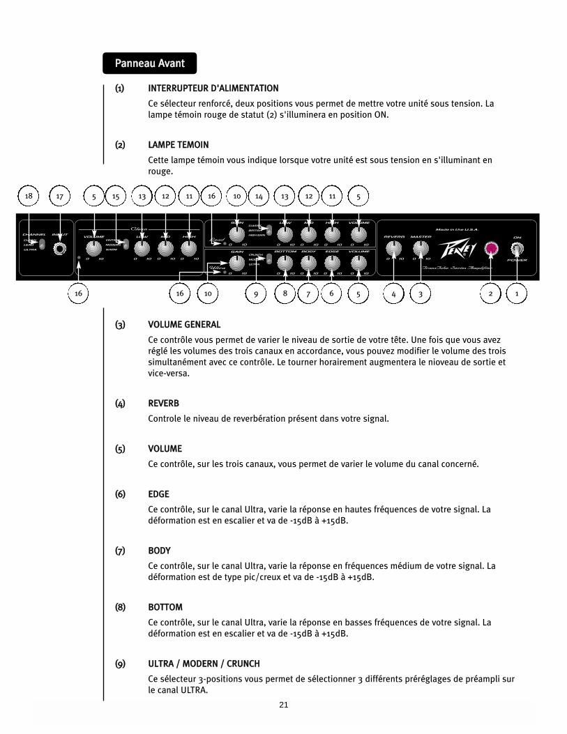
PPaannnneeaauu AAvvaanntt
((11)) IINNTTEERRRRUUPPTTEEUURR DD''AALLIIMMEENNTTAATTIIOONN
Ce sélecteur renforcé, deux positions vous permet de mettre votre unité sous tension. La
lampe témoin rouge de statut (2) s'illuminera en position ON.
((22)) LLAAMMPPEE TTEEMMOOIINN
Cette lampe témoin vous indique lorsque votre unité est sous tension en s'illuminant en
rouge.
((33)) VVOOLLUUMMEE GGEENNEERRAALL
Ce contrôle vous permet de varier le niveau de sortie de votre tête. Une fois que vous avez
réglé les volumes des trois canaux en accordance, vous pouvez modifier le volume des trois
simultanément avec ce contrôle. Le tourner horairement augmentera le nioveau de sortie et
vice-versa.
((44)) RREEVVEERRBB
Controle le niveau de reverbération présent dans votre signal.
((55)) VVOOLLUUMMEE
Ce contrôle, sur les trois canaux, vous permet de varier le volume du canal concerné.
((66)) EEDDGGEE
Ce contrôle, sur le canal Ultra, varie la réponse en hautes fréquences de votre signal. La
déformation est en escalier et va de -15dB à +15dB.
((77)) BBOODDYY
Ce contrôle, sur le canal Ultra, varie la réponse en fréquences médium de votre signal. La
déformation est de type pic/creux et va de -15dB à +15dB.
((88)) BBOOTTTTOOMM
Ce contrôle, sur le canal Ultra, varie la réponse en basses fréquences de votre signal. La
déformation est en escalier et va de -15dB à +15dB.
((99)) UULLTTRRAA // MMOODDEERRNN // CCRRUUNNCCHH
Ce sélecteur 3-positions vous permet de sélectionner 3 différents préréglages de préampli sur
le canal ULTRA.
1234567816 9
510 14161518 1112131213 11517
1016
22
((1100)) GGAAIINN
Ce contrôle, sur les deux canaux LEAD (saturé) et ULTRA, vous permet de varier le niveau
d'entrée du préampli correspondant. En le tournant dans le sens horaire, vous augmentez le
niveau du gain et donc celui de saturation du signal.
((1111)) HHIIGGHH
Ce contrôle passif, sur les deux canaux CLEAN (clair) et LEAD (saturé) vous permet de filtrer la
réponse des fréquences aigues du préampli correspondant.
((1122)) MMIIDD
Ce contrôle passif, sur les deux canaux CLEAN (clair) et LEAD (saturé) vous permet de filtrer la
réponse des fréquences médium du préampli correspondant.
((1133)) LLOOWW
Ce contrôle passif, sur les deux canaux CLEAN (clair) et LEAD (saturé) vous permet de filtrer la
réponse des fréquences graves du préampli correspondant.
((1144)) HHIIGGHH GGAAIINN // BBRRIITTIISSHH // CCLLAASSSSIICC
Ce sélecteur 3-positions vous permet de sélectionner 3 différents préréglages de préampli sur
le canal LEAD (saturé).
((1155)) WWAARRMM // MMOODDEERRNN // VVIINNTTAAGGEE
Ce sélecteur 3-positions vous permet de sélectionner 3 différents préréglages de préampli sur
le canal CLEAN (clair).
((1166)) LLEEDDSS DD’’AACCTTIIVVAATTIIOONN DDEE CCAANNAALL
Ces indicateurs indiquent quel canal est actif. L’activation du canal ULTRA illuminera le Led en
rouge, le canal LEAD (saturé) en jaune et le CLEAN (clair) en vert.
((1177)) EENNTTRREEEE
Ce jack 1/4" est prévue pour recevoir le signal de tout type de guitare électrique standard.
((1188)) CCAANNAAUUXX
Ce sélecteur 3-positions vous permet de sélectionner le canal actif parmis les trois de votre
XXL. Les Leds d’activation de canal (16) indique le préampli actif. Le changement de canal
peut également s'effectuer au moyen du pédalier fourni. Référez-vous à la section pédalier
plus loin dans ce manuel pour de plus amples informations. Ce sélecteur doit être en position
ULTRA pour permettre le changement de canal au pied.
23
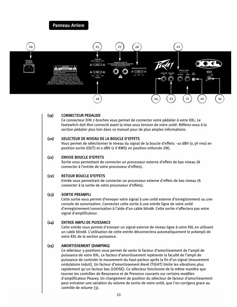
PPaannnneeaauu AArrrriieerree
((1199)) CCOONNNNEECCTTEEUURR PPEEDDAALLIIEERR
Ce connecteur DIN 7-broches vous permet de connecter votre pédalier à votre XXL. Le
footswitch doit être connecté avant la mise sous tension de votre unité. Référez-vous à la
section pédalier plus loin dans ce manuel pour de plus amples informations.
((2200)) SSEELLEECCTTEEUURR DDEE NNIIVVEEAAUU DDEE LLAA BBOOUUCCLLEE DD''EEFFFFEETTSS
Vous permet de sélectionner le niveau du signal de la boucle d’effets: -10 dBV (0.3V rms) en
position sortie (OUT) et 0 dBV (1 V RMS) en position enfoncée (IN).
((2211)) EENNVVOOIIEE BBOOUUCCLLEE DD’’EEFFFFEETTSS
Sortie vous permettant de connecter un processeur externe d’effets de bas niveau (A
connecter à l’entrée de votre processeur d’effets).
((2222)) RREETTOOUURR BBOOUUCCLLEE DD’’EEFFFFEETTSS
Entrée vous permettant de connecter un processeur externe d'effets de bas niveau (A
connecter à la sortie de votre processeur d’effets).
((2233)) SSOORRTTIIEE PPRREEAAMMPPLLII
Cette sortie vous permet d’envoyer votre signal à une unité externe d’enregistrement ou une
console de sonorisation. Connectez cette sortie à une entrée ligne de votre unité
d’enregistrement/sonorisation à l’aide d’un cable blindé. Cette sortie n’affectera pas votre
signal d’amplificateur.
((2244)) EENNTTRREEEE AAMMPPLLII DDEE PPUUIISSSSAANNCCEE
Cette entrée vous permet d'envoyer un signal externe de niveau ligne à votre XXL en utilisant
un cable blindé. L’utilisation de cette entrée déconnectera automatiquement le préampli de
votre XXL de la section puissance.
((2255)) AAMMOORRTTIISSSSEEMMEENNTT ((DDAAMMPPIINNGG))
Ce sélecteur 3-positions vous permet de varier le facteur d’amortissement de l’ampli de
puissance de votre XXL. Le facteur d’amortissement repésente la faculté de l’ampli de
puissance de controler le mouvement du haut-parleur après la fin d’un signal (mouvement
ondulatoire induit). Un facteur d’amortissement élevé (TIGHT) limite les vibrations plus
rapidement qu'un facteur bas (LOOSE). Ce sélecteur fonctionne de la même manière que
tourner les contrôles de Resonance et de Presence courants sur certains modèles
d'amplificateur Peavey. Un changement de position du sélecteur de facteur d’amortissement
peut entrainer une variation du volume de sortie de votre unité, que l'on corrigera grace au
contrôle de volume (3).
212326
222529
192024
27 28
24
((2266)) PPUUIISSSSAANNCCEE DDEE SSOORRTTIIEE
Ce sélecteur 3-positions vous permet de varier la puissance de sortie de votre XXL. Il
fonctionne de la même manière que tourner le contrôle de T. DynamicsÆ courant sur certains
modèles d'amplificateur Peavey. Il vous permet d'obtenir des taux de saturation très élevés
même à bas volume (simulation de compression d'un étage de puissance à plein rendement).
((2277)) SSOORRTTIIEESS HHAAUUTT--PPAARRLLEEUURRSS
Ces jacks 1/4" mono (TS) sont montés en parallèle et vous permettent de connecter votre XXL
à une ou plusieurs enceintes guitare. La charge minimum de sortie est de 4 Ohms. Le
sélecteur d'impédance (28) doit être positionné en fonction de la charge globale de votre XXL.
((2288)) SSEELLEECCTTEEUURR DD''IIMMPPEEDDAANNCCEE
Ce sélecteur 3-positions vous permet de sélectionner l’impédance de sortie de votre XXL.
Cette valeur doit correspondre à la charge totale des enceintes connectées à celle-ci. Si une
seule enceinte est utilisée, la valeur de ce sélecteur doit correspondre à l’impédance de
l'enceinte. Si deux enceintes de même impédance sont connectées, le sélecteur doit être
placé sur la valeur de la moitié de l’impédance d’une seule enceinte. Par exemple, deux
enceintes de 8 Ohms donnent 4 Ohms, valeur à sélectionner; Deux enceintes de 16 Ohms
donnent 8 Ohms, valeur à sélectionner. L’impédance du système d’enceinte(s) doit être
supérieure à 4 Ohms.
((2299)) CCOONNNNEECCTTEEUURR DD’’AALLIIMMEENNTTAATTIIOONN IIEECC
La XXL dispose d’une prise d’alimentation IEC permettant de connecter un cordon
d’alimentation standard aux normes IEC. L’appareil doit toujours être relié à la terre et
alimenté par une source dont les caractéristiques correspondent à celles indiquées à côté de
la prise d’alimentation. Votre sécurité en dépend.
25
FFoooottsswwiittcchh
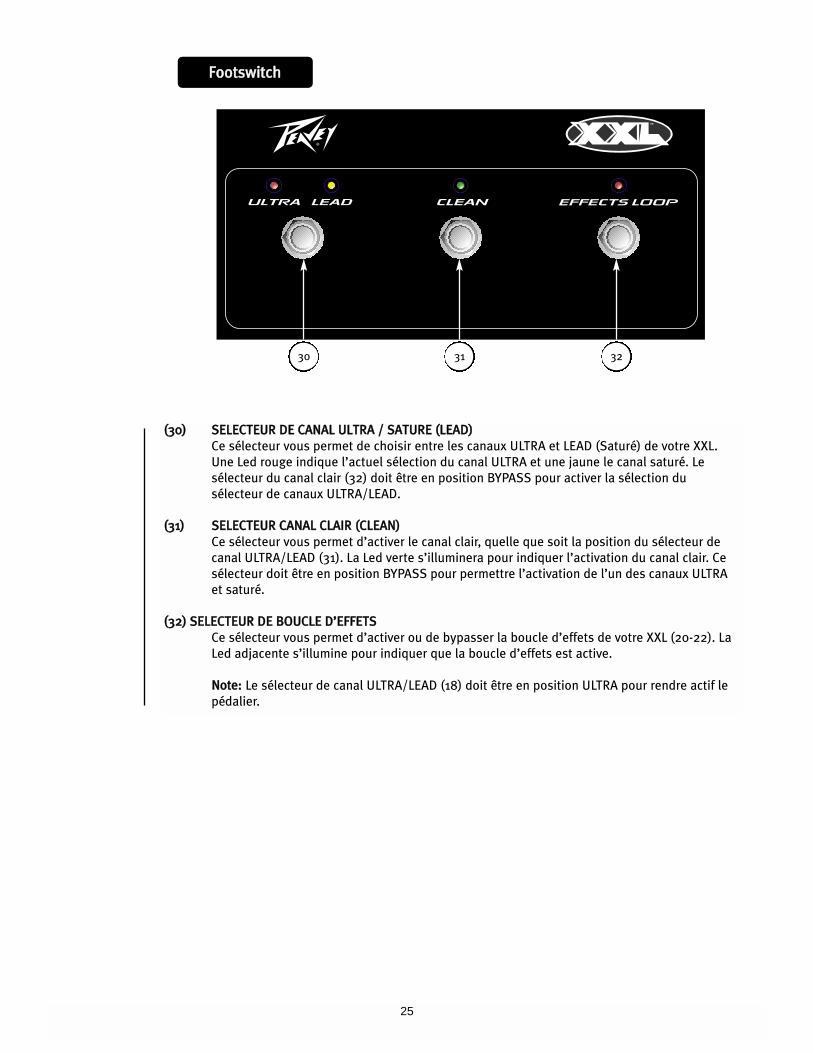
((3300)) SSEELLEECCTTEEUURR DDEE CCAANNAALL UULLTTRRAA // SSAATTUURREE ((LLEEAADD))
Ce sélecteur vous permet de choisir entre les canaux ULTRA et LEAD (Saturé) de votre XXL.
Une Led rouge indique l’actuel sélection du canal ULTRA et une jaune le canal saturé. Le
sélecteur du canal clair (32) doit être en position BYPASS pour activer la sélection du
sélecteur de canaux ULTRA/LEAD.
((3311)) SSEELLEECCTTEEUURR CCAANNAALL CCLLAAIIRR ((CCLLEEAANN))
Ce sélecteur vous permet d’activer le canal clair, quelle que soit la position du sélecteur de
canal ULTRA/LEAD (31). La Led verte s’illuminera pour indiquer l’activation du canal clair. Ce
sélecteur doit être en position BYPASS pour permettre l’activation de l’un des canaux ULTRA
et saturé.
((3322)) SSEELLEECCTTEEUURR DDEE BBOOUUCCLLEE DD’’EEFFFFEETTSS
Ce sélecteur vous permet d’activer ou de bypasser la boucle d’effets de votre XXL (20-22). La
Led adjacente s’illumine pour indiquer que la boucle d’effets est active.
NNoottee:: Le sélecteur de canal ULTRA/LEAD (18) doit être en position ULTRA pour rendre actif le
pédalier.
30 31 32
26
PPoowweerr AAmmpplliiffiieerr SSeeccttiioonn::RRaatteedd ppoowweerr aanndd llooaadd::
100 W RMS into 16, 8, or 4 Ohms
PPoowweerr aatt cclliippppiinngg::
(typically @ 5% THD, 1 kHz, 120 VAC line)
100 W RMS into 16, 8, or 4 Ohms
FFrreeqquueennccyy rreessppoonnssee::
+0 dB, -3 dB, 50 Hz to 38 kHz @ 60 W
RMS into 16 Ohms
HHuumm aanndd nnooiissee::
Greater than 85 dB below rated power
PPoowweerr ccoonnssuummppttiioonn::
Domestic: 300 W, 60 Hz, 120 VAC
Export: 300 W, 50/60 Hz, 220-240 VAC
PPRREEAAMMPP SSEECCTTIIOONN::The following specs are measured @
1 kHz with the controls preset as follows:
Low and High EQ @ 10, Mid EQ @ 0
Ultra and Lead Volumes @ 5
Bottom and Edge EQ @ 10
Body EQ @ 5
Master Volume @ 10
Reverb @ 0
Nominal Levels are with Gain/Clean
Volume @ 5
Minimum Levels are with Gain/Clean
Volume @ 10
Damping @ TIGHT
Power @ 100 W
CClleeaann cchhaannnneell ((vviinnttaaggee))::
Nominal Input Level: -22.7 dB, 73 mV RMS
Minimum Input Level: -30.8 dB, 29 mV RMS
Maximum Input Level: -2.33 dB, 765 mV RMS
LLeeaadd cchhaannnneell ((ccllaassssiicc))::
Nominal Input Level: -26.2 dB, 49 mV RMS
Minimum Input Level: -46.0 dB, 5 mV RMS
UUllttrraa cchhaannnneell ((uullttrraa))::
Nominal Input Level: -60 dB, 1 mV RMS
Minimum Input Level: -80 dB, 0.1 mV RMS
EEffffeeccttss sseenndd::
Load Impedance: 1 k Ohms or greater
Nominal Output Level:
Effects Level switch “out”: -10.9 dBV,
285 mV RMS
Effects Level switch “in”: -1.41 dBV,
850 mV RMS
EEffffeeccttss rreettuurrnn::
Impedance: High Z, 22 k Ohms
Designed Input Level:
Effects Level switch “out”: -10.9 dBV,
285 mV RMS
Effects Level switch “in”: -1.41 dBV,
850 mV RMS
(Switching jack provides Effects Send to
Effects Return connection when not
used)
PPrreeaammpp oouuttppuutt::
Load Impedance: 1 k Ohms or greater
Nominal Output Level: -1.94 dBV,
800 mV RMS
PPoowweerr aammpp iinnppuutt::
Impedance: High Z, 22 k Ohms
Designed Input Level: -1.94 dBV,
800 mV RMS
(Switching jack provides preamp output to
power amp input connection when not
used)
SSyysstteemm hhuumm aanndd nnooiissee @@ nnoommiinnaall iinnppuutt
lleevveell::
(Clean channel, Modern, 20 Hz to 20 kHz
unweighted)
Greater than 72 dB below rated power
EEqquuaalliizzaattiioonn::
Clean and Lead channels:
Low, Mid, and High passive EQ with
three distinct voicings.
Ultra channel: Bottom, Body, and Edge
active EQ with 15 dB boost/cut on each
band.
RReemmoottee ffoooottsswwiittcchh::
Special three-button unit with LED
indicators (included)
DDiimmeennssiioonnss::
20.75" H x 26.5"W x 11.25" D
527 mm H x 673 mm W x 286 mm D
WWeeiigghhtt::
63.7 lbs. (28.9 kg)
SSPPEECCIIFFIICCAATTIIOONNSS DDUU
XXXXLL™™ 221122 CCOOMMBBOO

27
DDEEUUTTSSCCHH
Großartige Ausstattung... großartiger Sound. Der XXL™ 212 COMBO ist das herausragende Ergebnis von fast einem gesamten
Jahrzehnt der Verbesserungen und Feinarbeiten an Peaveys innovativer TransTube®-Vakuumröhren-Emulationsschaltung.
Produkt dieser Bemühungen ist ein beeindruckender Verstärker, der die heißesten Röhrenverstärker-Soundvarianten präzise
wiedergibt, die man sich nur vorstellen kann... und zwar Sounds von gestern und von heute. Drei vollständig unabhängige
Kanäle (Clean/Passive EQ, Lead/Passive EQ und Ultra/Active EQ) liefern Ihnen eine Palette an Sounds, mit der Sie Ihrer
Fantasie freien Lauf lassen können. Von den brillanten Clean-Sounds des “Vintage”-Modus über den nahezu unkontrollierbaren
Scream des “Ultra”-Modus bis hin zur extremen Flexibilität der neuen TransTube-Verstärkerdämpfung und der
Leistungspegelschalter – der XXL 212 COMBO wird Sie faszinieren, sobald Sie ihn einschalten. Dieser Gigant, der eine
umwerfende Leistung von über 100 Watt mit seinen beiden 12" Blue Marvel-Lautsprechern (oder mit jeder üblichen
Gitarrenbox) liefert, kann den größten Veranstaltungsraum zum Beben bringen oder – durch Drehen des Master Volume und
Umschalten des 25/50/100 Watt-Leistungspegelschalters – die Gäste in der kleinsten Bar fesseln. Über die per Fußschalter
regelbare Effektschleife können durch externe Effekte weitere Klangexplosionen erzeugt werden. Als Sahnehäubchen ist eine
zusätzliche Reverb-Funktion vorhanden. Selbst ein robuster Fußschalter als Dreingabe sowie eine klassische facettierte
Kontrollleuchte sind vorhanden, sodass Sie über sämtliche Werkzeuge verfügen, um ALLE Grenzen zu überschreiten. Der
brandneue Peavey XXL 212 COMBO... jetzt gibt’s keine Entschuldigungen mehr.
MMEERRKKMMAALLEE::
• Zwei 12" Blue Marvel-Lautsprecher
• Drei vollständig unabhängige Kanäle
• Aktiver Bottom-, Body- und Edge-EQ im Ultra-Kanal
• Passiver Dreiband-EQ in Clean- und Lead-Kanälen
• EQ mit drei Positionen und Gain-Voicing-Schalter in jedem Kanal
• 100 W (RMS) an 4, 8 oder 16 Ohm (Impedanz wählbar)
• Leistungspegelschalter für den Betrieb mit 25 W, 50 W oder 100 W
• Verstärker-Dämpfungsschalter (Tight, Medium, Loose)
• Über Fußschalter regelbare Effektschleife mit Effektpegelregler
• Anschlussklinken für Vorverstärkerausgang und Verstärkereingang
• Reverb
• Master Volume
• Dreitasten-Fußschalter aus Metall mit abziehbarem Kabel (760 mm, beiliegend)
• Klassische facettierte Kontrollleuchte
• Verchromte Reglerknöpfe aus Messing
28
1234567816
FFrroonntt PPaanneell
9
510 14161518 1112131213 11517
1016
((11)) PPOOWWEERR--SSCCHHAALLTTEERR ((NNEETTZZSSCCHHAALLTTEERR))
Über diesen robusten Wippschalter wird das Gerät mit Netzstrom versorgt. Die rote POWER
STATUS-LAMPE (2) leuchtet auf, wenn dieser Schalter auf ON steht.
((22)) PPOOWWEERR SSTTAATTUUSS--LLAAMMPPEE
Diese Anzeige leuchtet auf, wenn der Verstärker mit Netzstrom versorgt wird.
((33)) MMAASSTTEERR VVOOLLUUMMEE
Mit diesem Regler wird der Gesamtlautstärkepegel des Verstärkers festgelegt. Ist der
gewünschte Abgleich zwischen den drei Kanälen des Verstärkers erzielt, kann der
Ausgangspegel des Gerätes durch Drehen dieses Reglers insgesamt erhöht oder gesenkt
werden. Durch Drehen im Uhrzeigersinn wird der Pegel erhöht, durch Drehen in den
entgegengesetzten Uhrzeigersinn wird er gesenkt.
((44)) RREEVVEERRBB
Mit diesem Regler wird der Gesamtpegel des Reverb eingestellt.
((55)) VVOOLLUUMMEE
Mit diesem Regler wird – bei allen drei Kanälen – der Gesamtpegel des jeweiligen Kanals
festgelegt.
((66)) EEDDGGEE
Mit diesem Regler wird beim Ultra-Kanal das Ansprechen des Verstärkers bei hohen
Frequenzen eingestellt. Dieser aktive Klangregler (stufenlos verstellbar) ermöglicht ein
Anheben oder Absenken um 15 dB.
((77)) BBOODDYY
Mit diesem Regler wird beim Ultra-Kanal das Ansprechen des Verstärkers bei mittleren
Frequenzen eingestellt. Dieser aktive Klangregler (Spitze/Kerbe) ermöglicht ein Anheben oder
Absenken um 15 dB.
((88)) BBOOTTTTOOMM
Mit diesem Regler wird beim Ultra-Kanal das Ansprechen des Verstärkers bei niedrigen
Frequenzen eingestellt. Dieser aktive Klangregler (stufenlos verstellbar) ermöglicht ein
Anheben oder Absenken um 15 dB.
29
((99)) UULLTTRRAA//MMOODDEERRNN//CCRRUUNNCCHH
Über die drei Positionen dieses Schalters wählen Sie zwischen den drei unterschiedlichen
Gain- und EQ-Voicings im Ultra-Kanal aus.
((1100)) GGAAIINN
Mit diesem Regler, der sowohl am Ultra- als auch am Lead-Kanal vorhanden ist, wird der
Eingangslautstärkepegel des jeweiligen Kanals eingestellt. Durch Drehen dieses Reglers im
Uhrzeigersinn wird der Grad an Verzerrung und Sustain des Vorverstärkers erhöht.
((1111)) HHIIGGHH
Mit diesem passiven Regler, der sowohl am Clean- als auch am Lead-Kanal vorhanden ist, wird
das Ansprechen des jeweiligen Kanals bei hohen Frequenzen geregelt.
((1122)) MMIIDD
Mit diesem passiven Regler, der sowohl am Clean- als auch am Lead-Kanal vorhanden ist, wird
das Ansprechen des jeweiligen Kanals bei mittleren Frequenzen geregelt.
((1133)) LLOOWW
Mit diesem passiven Regler, der sowohl am Clean- als auch am Lead-Kanal vorhanden ist, wird
das Ansprechen des jeweiligen Kanals bei niedrigen Frequenzen geregelt.
((1144)) HHIIGGHH GGAAIINN//BBRRIITTIISSHH//CCLLAASSSSIICC
Über die drei Positionen dieses Schalters wählen Sie zwischen den drei unterschiedlichen EQ-
und Gain-Voicings im Lead-Kanal aus.
((1155)) WWAARRMM//MMOODDEERRNN//VVIINNTTAAGGEE
Über die drei Positionen dieses Schalters wählen Sie zwischen den drei unterschiedlichen EQ-
Voicings im Clean-Kanal aus.
((1166)) CCHHAANNNNEELL--AACCTTIIVVAATTIIOONN--LLEEDDss
Diese Anzeigen zeigen den aktiven Kanal an. Bei aktivem Ultra-Kanal leuchtet die rote LED
auf. Bei aktivem Lead-Kanal leuchtet die gelbe LED auf, bei aktivem Clean-Kanal die grüne
LED.
((1177)) IINNPPUUTT
An diese 1/4"-Klinke können Signale von jeder üblichen Elektrogitarre angeschlossen werden.
((1188)) CCHHAANNNNEELL
Über die drei Positionen dieses Kippschalters wählen Sie zwischen den drei Kanälen des XXL
212 COMBO aus. Die CHANNEL-ACTIVATION-LEDs (16) zeigen an, welcher Kanal aktiv ist. Die
Kanalumschaltung kann auch über den beiliegenden Fußschalter erfolgen. Erläuterungen zum
Betrieb dieses Schalters entnehmen Sie bitte dem Abschnitt FUSSSCHALTER in dieser
Anleitung. Der CHANNEL-Schalter muss auf der Position ULTRA stehen, damit der Fußschalter
korrekt arbeiten kann.
30
RReeaarr PPaanneell
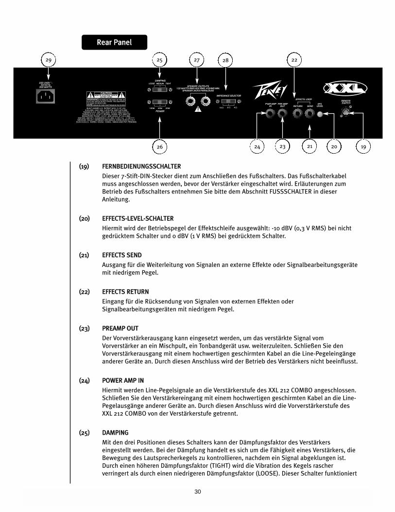
((1199)) FFEERRNNBBEEDDIIEENNUUNNGGSSSSCCHHAALLTTEERR
Dieser 7-Stift-DIN-Stecker dient zum Anschließen des Fußschalters. Das Fußschalterkabel
muss angeschlossen werden, bevor der Verstärker eingeschaltet wird. Erläuterungen zum
Betrieb des Fußschalters entnehmen Sie bitte dem Abschnitt FUSSSCHALTER in dieser
Anleitung.
((2200)) EEFFFFEECCTTSS--LLEEVVEELL--SSCCHHAALLTTEERR
Hiermit wird der Betriebspegel der Effektschleife ausgewählt: -10 dBV (0,3 V RMS) bei nicht
gedrücktem Schalter und 0 dBV (1 V RMS) bei gedrücktem Schalter.
((2211)) EEFFFFEECCTTSS SSEENNDD
Ausgang für die Weiterleitung von Signalen an externe Effekte oder Signalbearbeitungsgeräte
mit niedrigem Pegel.
((2222)) EEFFFFEECCTTSS RREETTUURRNN
Eingang für die Rücksendung von Signalen von externen Effekten oder
Signalbearbeitungsgeräten mit niedrigem Pegel.
((2233)) PPRREEAAMMPP OOUUTT
Der Vorverstärkerausgang kann eingesetzt werden, um das verstärkte Signal vom
Vorverstärker an ein Mischpult, ein Tonbandgerät usw. weiterzuleiten. Schließen Sie den
Vorverstärkerausgang mit einem hochwertigen geschirmten Kabel an die Line-Pegeleingänge
anderer Geräte an. Durch diesen Anschluss wird der Betrieb des Verstärkers nicht beeinflusst.
((2244)) PPOOWWEERR AAMMPP IINN
Hiermit werden Line-Pegelsignale an die Verstärkerstufe des XXL 212 COMBO angeschlossen.
Schließen Sie den Verstärkereingang mit einem hochwertigen geschirmten Kabel an die Line-
Pegelausgänge anderer Geräte an. Durch diesen Anschluss wird die Vorverstärkerstufe des
XXL 212 COMBO von der Verstärkerstufe getrennt.
((2255)) DDAAMMPPIINNGG
Mit den drei Positionen dieses Schalters kann der Dämpfungsfaktor des Verstärkers
eingestellt werden. Bei der Dämpfung handelt es sich um die Fähigkeit eines Verstärkers, die
Bewegung des Lautsprecherkegels zu kontrollieren, nachdem ein Signal abgeklungen ist.
Durch einen höheren Dämpfungsfaktor (TIGHT) wird die Vibration des Kegels rascher
verringert als durch einen niedrigeren Dämpfungsfaktor (LOOSE). Dieser Schalter funktioniert
212326
222529
192024
27 28
31
ähnlich wie die Resonance- und Presence-Regler an anderen Peavey-Verstärkern, wenn sie
gleichzeitig gedreht werden. Wird der Dämpfungsschalter verstellt, verändert sich auch der
Lautstärkepegel des Verstärkers, sodass eventuell das Master Volume (3) neu eingestellt
werden muss.
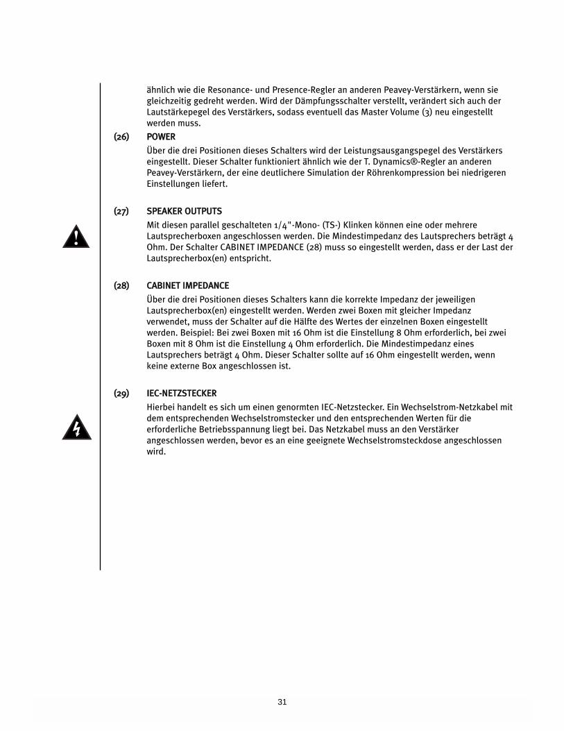
((2266)) PPOOWWEERR
Über die drei Positionen dieses Schalters wird der Leistungsausgangspegel des Verstärkers
eingestellt. Dieser Schalter funktioniert ähnlich wie der T. Dynamics®-Regler an anderen
Peavey-Verstärkern, der eine deutlichere Simulation der Röhrenkompression bei niedrigeren
Einstellungen liefert.
((2277)) SSPPEEAAKKEERR OOUUTTPPUUTTSS
Mit diesen parallel geschalteten 1/4"-Mono- (TS-) Klinken können eine oder mehrere
Lautsprecherboxen angeschlossen werden. Die Mindestimpedanz des Lautsprechers beträgt 4
Ohm. Der Schalter CABINET IMPEDANCE (28) muss so eingestellt werden, dass er der Last der
Lautsprecherbox(en) entspricht.
((2288)) CCAABBIINNEETT IIMMPPEEDDAANNCCEE
Über die drei Positionen dieses Schalters kann die korrekte Impedanz der jeweiligen
Lautsprecherbox(en) eingestellt werden. Werden zwei Boxen mit gleicher Impedanz
verwendet, muss der Schalter auf die Hälfte des Wertes der einzelnen Boxen eingestellt
werden. Beispiel: Bei zwei Boxen mit 16 Ohm ist die Einstellung 8 Ohm erforderlich, bei zwei
Boxen mit 8 Ohm ist die Einstellung 4 Ohm erforderlich. Die Mindestimpedanz eines
Lautsprechers beträgt 4 Ohm. Dieser Schalter sollte auf 16 Ohm eingestellt werden, wenn
keine externe Box angeschlossen ist.
((2299)) IIEECC--NNEETTZZSSTTEECCKKEERR
Hierbei handelt es sich um einen genormten IEC-Netzstecker. Ein Wechselstrom-Netzkabel mit
dem entsprechenden Wechselstromstecker und den entsprechenden Werten für die
erforderliche Betriebsspannung liegt bei. Das Netzkabel muss an den Verstärker
angeschlossen werden, bevor es an eine geeignete Wechselstromsteckdose angeschlossen
wird.
32
FFoooottsswwiittcchh
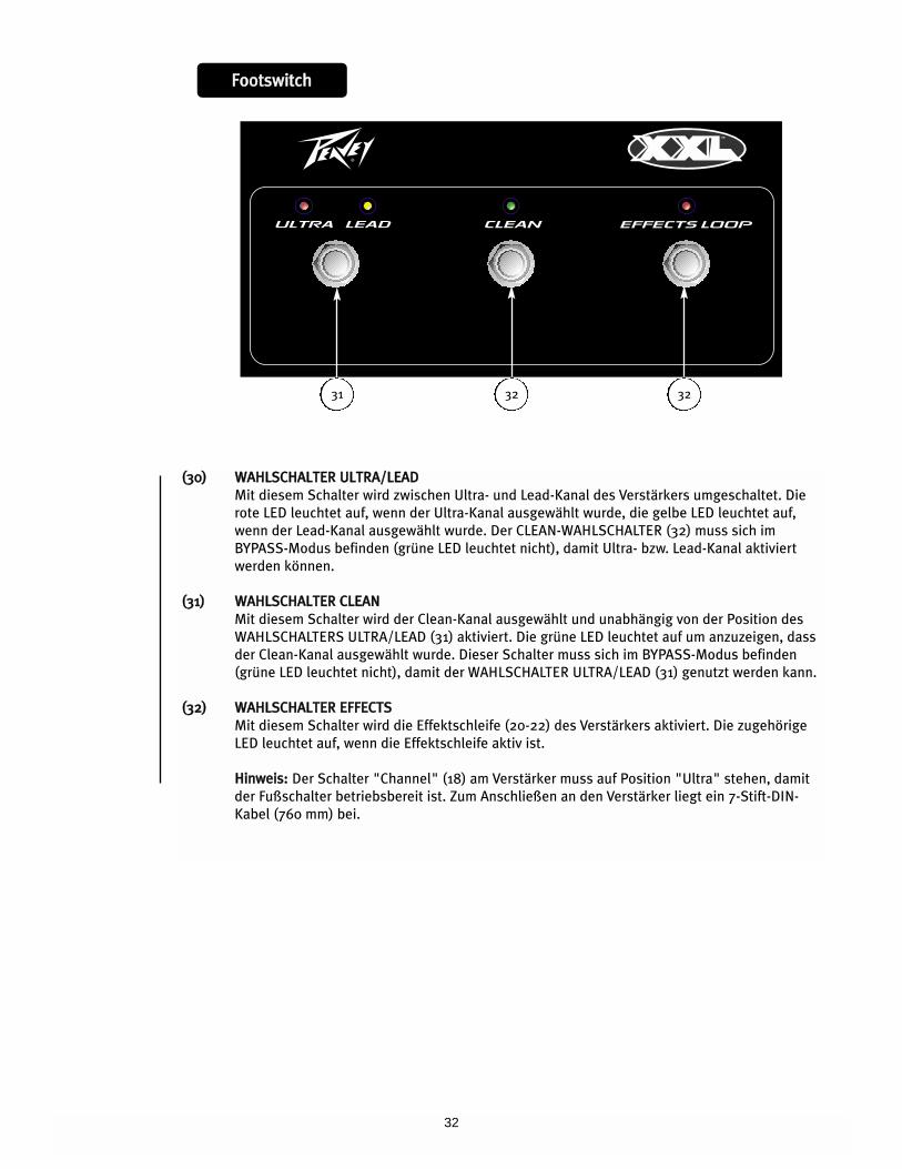
((3300)) WWAAHHLLSSCCHHAALLTTEERR UULLTTRRAA//LLEEAADD
Mit diesem Schalter wird zwischen Ultra- und Lead-Kanal des Verstärkers umgeschaltet. Die
rote LED leuchtet auf, wenn der Ultra-Kanal ausgewählt wurde, die gelbe LED leuchtet auf,
wenn der Lead-Kanal ausgewählt wurde. Der CLEAN-WAHLSCHALTER (32) muss sich im
BYPASS-Modus befinden (grüne LED leuchtet nicht), damit Ultra- bzw. Lead-Kanal aktiviert
werden können.
((3311)) WWAAHHLLSSCCHHAALLTTEERR CCLLEEAANN
Mit diesem Schalter wird der Clean-Kanal ausgewählt und unabhängig von der Position des
WAHLSCHALTERS ULTRA/LEAD (31) aktiviert. Die grüne LED leuchtet auf um anzuzeigen, dass
der Clean-Kanal ausgewählt wurde. Dieser Schalter muss sich im BYPASS-Modus befinden
(grüne LED leuchtet nicht), damit der WAHLSCHALTER ULTRA/LEAD (31) genutzt werden kann.
((3322)) WWAAHHLLSSCCHHAALLTTEERR EEFFFFEECCTTSS
Mit diesem Schalter wird die Effektschleife (20-22) des Verstärkers aktiviert. Die zugehörige
LED leuchtet auf, wenn die Effektschleife aktiv ist.
HHiinnwweeiiss:: Der Schalter "Channel" (18) am Verstärker muss auf Position "Ultra" stehen, damit
der Fußschalter betriebsbereit ist. Zum Anschließen an den Verstärker liegt ein 7-Stift-DIN-
Kabel (760 mm) bei.
31 32 32
33
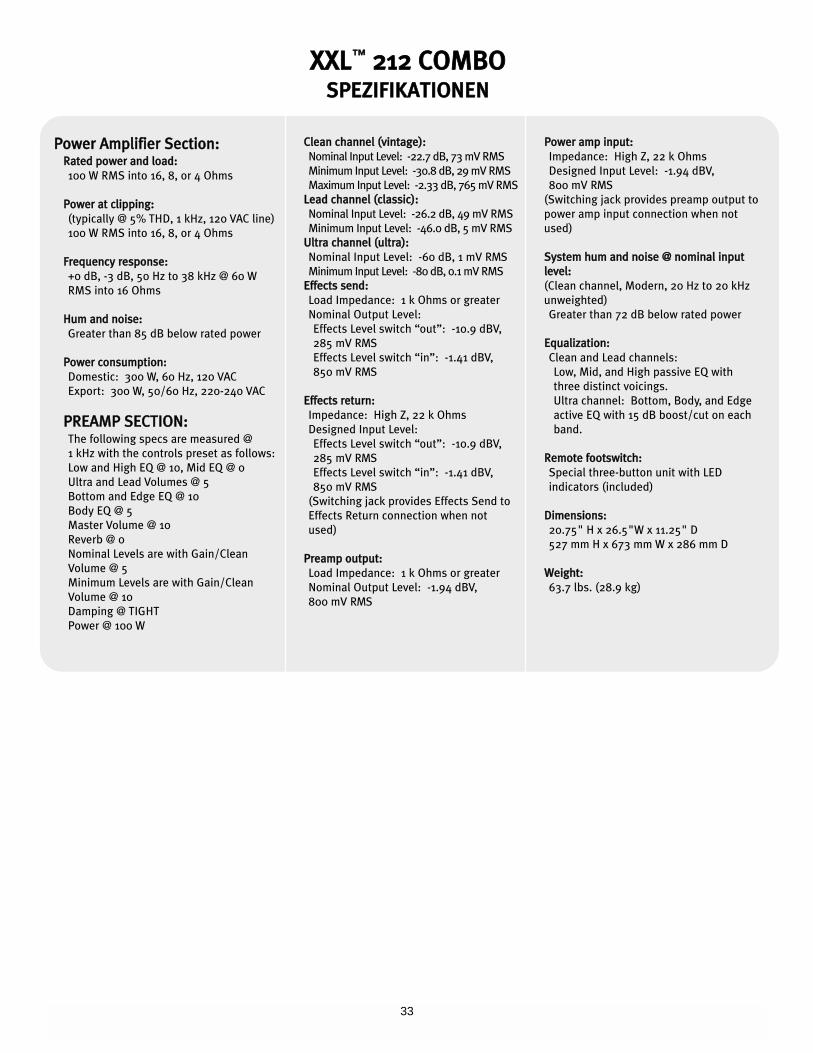
PPoowweerr AAmmpplliiffiieerr SSeeccttiioonn::RRaatteedd ppoowweerr aanndd llooaadd::
100 W RMS into 16, 8, or 4 Ohms
PPoowweerr aatt cclliippppiinngg::
(typically @ 5% THD, 1 kHz, 120 VAC line)
100 W RMS into 16, 8, or 4 Ohms
FFrreeqquueennccyy rreessppoonnssee::
+0 dB, -3 dB, 50 Hz to 38 kHz @ 60 W
RMS into 16 Ohms
HHuumm aanndd nnooiissee::
Greater than 85 dB below rated power
PPoowweerr ccoonnssuummppttiioonn::
Domestic: 300 W, 60 Hz, 120 VAC
Export: 300 W, 50/60 Hz, 220-240 VAC
PPRREEAAMMPP SSEECCTTIIOONN::The following specs are measured @
1 kHz with the controls preset as follows:
Low and High EQ @ 10, Mid EQ @ 0
Ultra and Lead Volumes @ 5
Bottom and Edge EQ @ 10
Body EQ @ 5
Master Volume @ 10
Reverb @ 0
Nominal Levels are with Gain/Clean
Volume @ 5
Minimum Levels are with Gain/Clean
Volume @ 10
Damping @ TIGHT
Power @ 100 W
CClleeaann cchhaannnneell ((vviinnttaaggee))::
Nominal Input Level: -22.7 dB, 73 mV RMS
Minimum Input Level: -30.8 dB, 29 mV RMS
Maximum Input Level: -2.33 dB, 765 mV RMS
LLeeaadd cchhaannnneell ((ccllaassssiicc))::
Nominal Input Level: -26.2 dB, 49 mV RMS
Minimum Input Level: -46.0 dB, 5 mV RMS
UUllttrraa cchhaannnneell ((uullttrraa))::
Nominal Input Level: -60 dB, 1 mV RMS
Minimum Input Level: -80 dB, 0.1 mV RMS
EEffffeeccttss sseenndd::
Load Impedance: 1 k Ohms or greater
Nominal Output Level:
Effects Level switch “out”: -10.9 dBV,
285 mV RMS
Effects Level switch “in”: -1.41 dBV,
850 mV RMS
EEffffeeccttss rreettuurrnn::
Impedance: High Z, 22 k Ohms
Designed Input Level:
Effects Level switch “out”: -10.9 dBV,
285 mV RMS
Effects Level switch “in”: -1.41 dBV,
850 mV RMS
(Switching jack provides Effects Send to
Effects Return connection when not
used)
PPrreeaammpp oouuttppuutt::
Load Impedance: 1 k Ohms or greater
Nominal Output Level: -1.94 dBV,
800 mV RMS
PPoowweerr aammpp iinnppuutt::
Impedance: High Z, 22 k Ohms
Designed Input Level: -1.94 dBV,
800 mV RMS
(Switching jack provides preamp output to
power amp input connection when not
used)
SSyysstteemm hhuumm aanndd nnooiissee @@ nnoommiinnaall iinnppuutt
lleevveell::
(Clean channel, Modern, 20 Hz to 20 kHz
unweighted)
Greater than 72 dB below rated power
EEqquuaalliizzaattiioonn::
Clean and Lead channels:
Low, Mid, and High passive EQ with
three distinct voicings.
Ultra channel: Bottom, Body, and Edge
active EQ with 15 dB boost/cut on each
band.
RReemmoottee ffoooottsswwiittcchh::
Special three-button unit with LED
indicators (included)
DDiimmeennssiioonnss::
20.75" H x 26.5"W x 11.25" D
527 mm H x 673 mm W x 286 mm D
WWeeiigghhtt::
63.7 lbs. (28.9 kg)
XXXXLL™™ 221122 CCOOMMBBOOSSPPEEZZIIFFIIKKAATTIIOONNEENN

34
NNOOTTEESS::
35
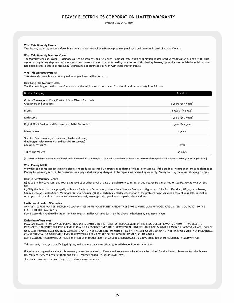
PEAVEY ELECTRONICS CORPORATION LIMITED WARRANTYEffective Date: July 1, 1998
WWhhaatt TThhiiss WWaarrrraannttyy CCoovveerrss
Your Peavey Warranty covers defects in material and workmanship in Peavey products purchased and serviced in the U.S.A. and Canada.
WWhhaatt TThhiiss WWaarrrraannttyy DDooeess NNoott CCoovveerr
The Warranty does not cover: (1) damage caused by accident, misuse, abuse, improper installation or operation, rental, product modification or neglect; (2) dam-
age occurring during shipment; (3) damage caused by repair or service performed by persons not authorized by Peavey; (4) products on which the serial number
has been altered, defaced or removed; (5) products not purchased from an Authorized Peavey Dealer.
WWhhoo TThhiiss WWaarrrraannttyy PPrrootteeccttss
This Warranty protects only the original retail purchaser of the product.
HHooww LLoonngg TThhiiss WWaarrrraannttyy LLaassttss
The Warranty begins on the date of purchase by the original retail purchaser. The duration of the Warranty is as follows:
Product Category Duration
Guitars/Basses, Amplifiers, Pre-Amplifiers, Mixers, Electronic
Crossovers and Equalizers 2 years *(+ 3 years)
Drums 2 years *(+ 1 year)
Enclosures 3 years *(+ 2 years)
Digital Effect Devices and Keyboard and MIDI Controllers 1 year *(+ 1 year)
Microphones 2 years
Speaker Components (incl. speakers, baskets, drivers,
diaphragm replacement kits and passive crossovers)
and all Accessories 1 year
Tubes and Meters 90 days
[*Denotes additional warranty period applicable if optional Warranty Registration Card is completed and returned to Peavey by original retail purchaser within 90 days of purchase.]
WWhhaatt PPeeaavveeyy WWiillll DDoo
We will repair or replace (at Peavey's discretion) products covered by warranty at no charge for labor or materials. If the product or component must be shipped to
Peavey for warranty service, the consumer must pay initial shipping charges. If the repairs are covered by warranty, Peavey will pay the return shipping charges.
HHooww TToo GGeett WWaarrrraannttyy SSeerrvviiccee
((11)) Take the defective item and your sales receipt or other proof of date of purchase to your Authorized Peavey Dealer or Authorized Peavey Service Center.
OR
((22)) Ship the defective item, prepaid, to Peavey Electronics Corporation, International Service Center, 412 Highway 11 & 80 East, Meridian, MS 39301 or Peavey
Canada Ltd., 95 Shields Court, Markham, Ontario, Canada L3R 9T5. Include a detailed description of the problem, together with a copy of your sales receipt or
other proof of date of purchase as evidence of warranty coverage. Also provide a complete return address.
LLiimmiittaattiioonn ooff IImmpplliieedd WWaarrrraannttiieess
ANY IMPLIED WARRANTIES, INCLUDING WARRANTIES OF MERCHANTABILITY AND FITNESS FOR A PARTICULAR PURPOSE, ARE LIMITED IN DURATION TO THE
LENGTH OF THIS WARRANTY.
Some states do not allow limitations on how long an implied warranty lasts, so the above limitation may not apply to you.
EExxcclluussiioonnss ooff DDaammaaggeess
PEAVEY'S LIABILITY FOR ANY DEFECTIVE PRODUCT IS LIMITED TO THE REPAIR OR REPLACEMENT OF THE PRODUCT, AT PEAVEY'S OPTION. IF WE ELECT TO
REPLACE THE PRODUCT, THE REPLACEMENT MAY BE A RECONDITIONED UNIT. PEAVEY SHALL NOT BE LIABLE FOR DAMAGES BASED ON INCONVENIENCE, LOSS OF
USE, LOST PROFITS, LOST SAVINGS, DAMAGE TO ANY OTHER EQUIPMENT OR OTHER ITEMS AT THE SITE OF USE, OR ANY OTHER DAMAGES WHETHER INCIDENTAL,
CONSEQUENTIAL OR OTHERWISE, EVEN IF PEAVEY HAS BEEN ADVISED OF THE POSSIBILITY OF SUCH DAMAGES.
Some states do not allow the exclusion or limitation of incidental or consequential damages, so the above limitation or exclusion may not apply to you.
This Warranty gives you specific legal rights, and you may also have other rights which vary from state to state.
If you have any questions about this warranty or service received or if you need assistance in locating an Authorized Service Center, please contact the Peavey
International Service Center at (601) 483-5365 / Peavey Canada Ltd. at (905) 475-2578.
Features and specifications subject to change without notice.

Features and specifications subject to change without notice.
Peavey Electronics Corporation • 711 A Street • Meridian, MS 39301
(601) 483-5365 • FAX (601) 486-1278 • www.peavey.com
©2002 Printed in the U.S.A. 10/0280304942