Embed Size (px)
Citation preview
Operating Instructions XWA11V dIXEL XWA11V_V8.8
Weiss Instruments, Inc. 905 Waverly Ave. Holtsville, NY 11742 631-207-1200 www.weissinstruments.com 1
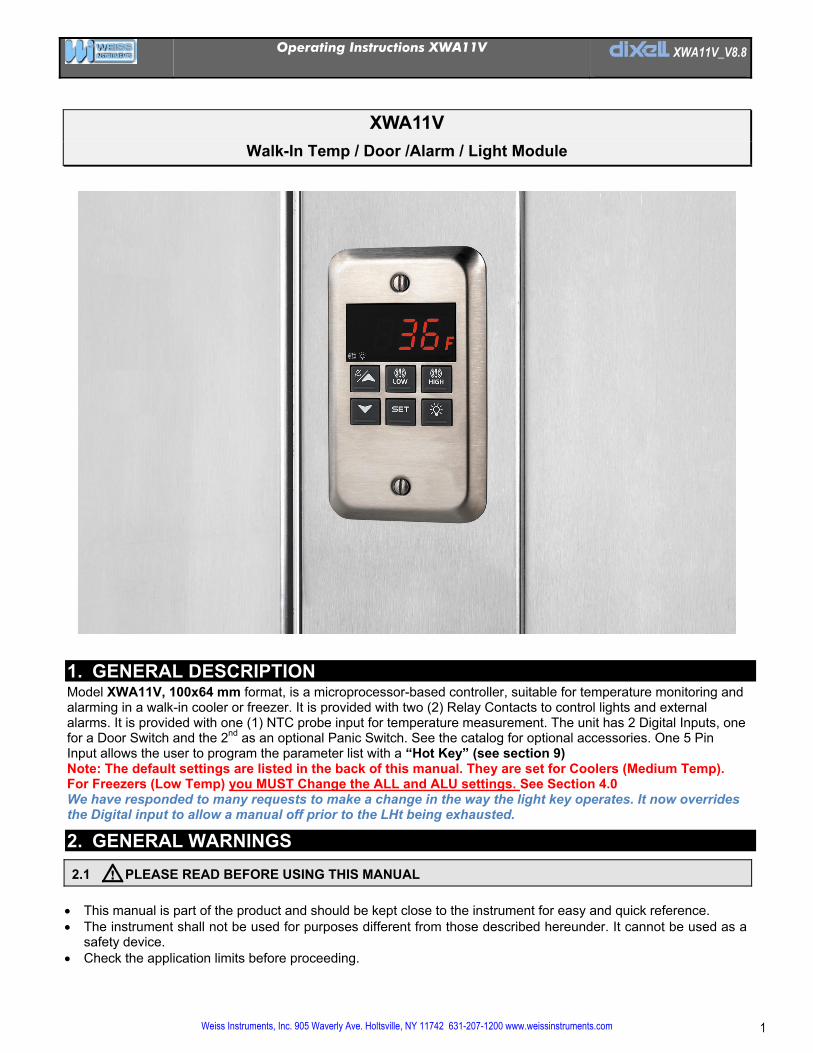
XWA11V
Walk-In Temp / Door /Alarm / Light Module
1. GENERAL DESCRIPTION Model XWA11V, 100x64 mm format, is a microprocessor-based controller, suitable for temperature monitoring and alarming in a walk-in cooler or freezer. It is provided with two (2) Relay Contacts to control lights and external alarms. It is provided with one (1) NTC probe input for temperature measurement. The unit has 2 Digital Inputs, one for a Door Switch and the 2nd as an optional Panic Switch. See the catalog for optional accessories. One 5 Pin Input allows the user to program the parameter list with a “Hot Key” (see section 9) Note: The default settings are listed in the back of this manual. They are set for Coolers (Medium Temp). For Freezers (Low Temp) you MUST Change the ALL and ALU settings. See Section 4.0 We have responded to many requests to make a change in the way the light key operates. It now overrides the Digital input to allow a manual off prior to the LHt being exhausted.
2. GENERAL WARNINGS
2.1 PLEASE READ BEFORE USING THIS MANUAL
This manual is part of the product and should be kept close to the instrument for easy and quick reference. The instrument shall not be used for purposes different from those described hereunder. It cannot be used as a
safety device. Check the application limits before proceeding.
Operating Instructions XWA11V dIXEL XWA11V_V8.8
Weiss Instruments, Inc. 905 Waverly Ave. Holtsville, NY 11742 631-207-1200 www.weissinstruments.com 2
2.2 SAFETY PRECAUTIONS READ ME FIRST! Check if the supply voltage is correct before connecting the instrument. Do not expose the back of the instrument to water or moisture: use the controller only within the operating limits
avoiding sudden temperature changes with high atmospheric humidity to prevent the formation of condensation. Be sure to seal any J-Box with RTV sealant to prevent cold and moisture intrusion. Warning: disconnect all electrical connections before performing any maintenance operation. Fit the probe where it is not damaged by the end-user. The instrument must not be opened. In case of failure or faulty operation send the instrument back to the distributor (see address) with a detailed description of
the fault. Consider the maximum current that can be applied to each relay (see Technical Data). Ensure that the wires for probes, loads and the power supply are separated and far enough from each other, without
crossing or intertwining or you may get bad temp readings.
3. INTERFACE
LOW HIGH
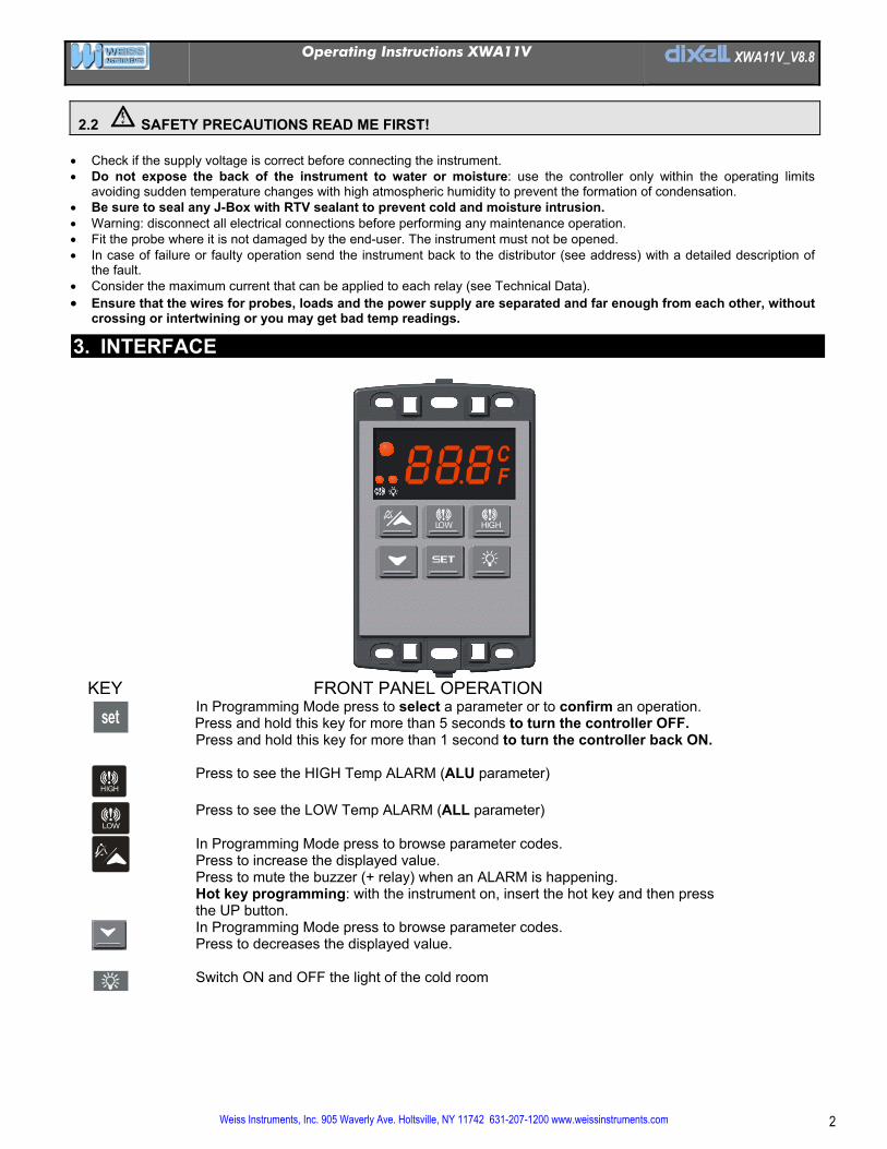
KEY FRONT PANEL OPERATION
In Programming Mode press to select a parameter or to confirm an operation. Press and hold this key for more than 5 seconds to turn the controller OFF.
Press and hold this key for more than 1 second to turn the controller back ON.
HIGH Press to see the HIGH Temp ALARM (ALU parameter)
LOW
Press to see the LOW Temp ALARM (ALL parameter)
In Programming Mode press to browse parameter codes. Press to increase the displayed value. Press to mute the buzzer (+ relay) when an ALARM is happening. Hot key programming: with the instrument on, insert the hot key and then press the UP button.
In Programming Mode press to browse parameter codes. Press to decreases the displayed value.
Switch ON and OFF the light of the cold room
Operating Instructions XWA11V dIXEL XWA11V_V8.8
Weiss Instruments, Inc. 905 Waverly Ave. Holtsville, NY 11742 631-207-1200 www.weissinstruments.com 3
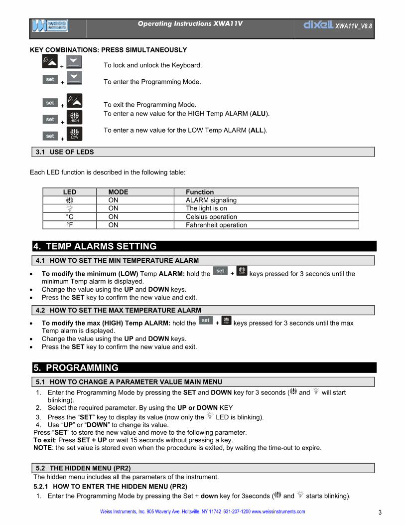
KEY COMBINATIONS: PRESS SIMULTANEOUSLY
+ To lock and unlock the Keyboard.
+ To enter the Programming Mode.
+ To exit the Programming Mode.
+ HIGH
To enter a new value for the HIGH Temp ALARM (ALU).
+ LOW
To enter a new value for the LOW Temp ALARM (ALL).
3.1 USE OF LEDS
Each LED function is described in the following table:
LED MODE Function
ON ALARM signaling
ON The light is on °C ON Celsius operation °F ON Fahrenheit operation
4. TEMP ALARMS SETTING
4.1 HOW TO SET THE MIN TEMPERATURE ALARM
To modify the minimum (LOW) Temp ALARM: hold the + LOW keys pressed for 3 seconds until the minimum Temp alarm is displayed.
Change the value using the UP and DOWN keys. Press the SET key to confirm the new value and exit.
4.2 HOW TO SET THE MAX TEMPERATURE ALARM
To modify the max (HIGH) Temp ALARM: hold the + HIGH keys pressed for 3 seconds until the max Temp alarm is displayed.
Change the value using the UP and DOWN keys. Press the SET key to confirm the new value and exit.
5. PROGRAMMING
5.1 HOW TO CHANGE A PARAMETER VALUE MAIN MENU
1. Enter the Programming Mode by pressing the SET and DOWN key for 3 seconds ( and will start blinking).
2. Select the required parameter. By using the UP or DOWN KEY
3. Press the “SET” key to display its value (now only the LED is blinking). 4. Use “UP” or “DOWN” to change its value.
Press “SET” to store the new value and move to the following parameter. To exit: Press SET + UP or wait 15 seconds without pressing a key. NOTE: the set value is stored even when the procedure is exited, by waiting the time-out to expire.
5.2 THE HIDDEN MENU (PR2) The hidden menu includes all the parameters of the instrument.
5.2.1 HOW TO ENTER THE HIDDEN MENU (PR2)
1. Enter the Programming Mode by pressing the Set + down key for 3seconds ( and starts blinking).
Operating Instructions XWA11V dIXEL XWA11V_V8.8
Weiss Instruments, Inc. 905 Waverly Ave. Holtsville, NY 11742 631-207-1200 www.weissinstruments.com 4
2. When a parameter is displayed, release and re-press the SET + down for more than 7 seconds. 3. The Pr2 label will be displayed immediately followed from the HY parameter. NOW YOU ARE IN THE
HIDDEN MENU. 4. Select the required parameter as above
5. Press the “SET” key to display its value (Now only the LED is blinking). 6. Use “UP” or “down” to change its value. 7. Press “SET” to store the new value and move to the following parameter.
To exit: Press SET + up or wait 15 seconds without pressing a key. NOTE: the set value is stored even when the procedure is exited by waiting the time-out to expire.
5.2.2 HOW TO MOVE A PARAMETER FROM THE HIDDEN MENU TO THE FIRST LEVEL AND VICEVERSA Each parameter present in the HIDDEN MENU can be removed or put into “THE FIRST LEVEL” (user level) by pressing “SET + down”. In HIDDEN MENU when a parameter is present in First Level the decimal point LED is on.
5.3 HOW TO LOCK THE KEYBOARD
1. Keep the UP and DOWN keys pressed for more than 3 seconds. 2. The “POF” message will be displayed and the keyboard will be locked. At this point it will be possible only to see
the Set Point or the MAX o MIN Temp stored 3. If a key is pressed more than 3 seconds the “POF” message will be displayed.
5.4 TO UNLOCK THE KEYBOARD Keep the UP and DOWN keys pressed together for more than 3 seconds. The “PON” message is displayed
6. LIGHT MANAGEMENT
6.1 TIMED REGULATION: I1L = Y With i1L = y the light remains on at least for the LHt parameter. The LHt timer is re-initialized every time the light button is pushed or the door is opened. With LHt=0 the light remains on until the light button is pushed again or when the door is closed. The light is switched on every time one of the following conditions happens:
the door is open (i1F = dor)*DOOR SWITCH PRESENT the presence sensor is activated (i2F = LHt)*OCCUPANCY SENSOR PRESENT the light button is pushed
The light is switched off when all the following conditions happen:
the LHt timer is exhausted the door is closed (i1F = dor)*DOOR SWITCH PRESENT the presence sensor is de-activated (i2F = LHt)*OCCUPANCY SENSOR PRESENT Light button regulation: i1L = n The light button is pressed
FLH (opera mode) The lights will flash (for 2 minutes) every 20 seconds for the FLH time (0-5 min) before the end of the LHt time as a warning that the lights are about to turn off. (This should only be used for incandescent or LED lighting only!)
6.2 MANUAL OVERRIDE VIA THE LIGHT BUTTON
On the XWA11V version 8.8 it is now possible to turn the light off regardless of the Door Switch conditions. The light button on the face of the control takes precidence over the digital input, and the LHt parameter. This allows for the LHt to remain as a back-up in case the light button has not been pressed to turn the light off.
Operating Instructions XWA11V dIXEL XWA11V_V8.8
Weiss Instruments, Inc. 905 Waverly Ave. Holtsville, NY 11742 631-207-1200 www.weissinstruments.com 5
7. INSTALLATION AND MOUNTING
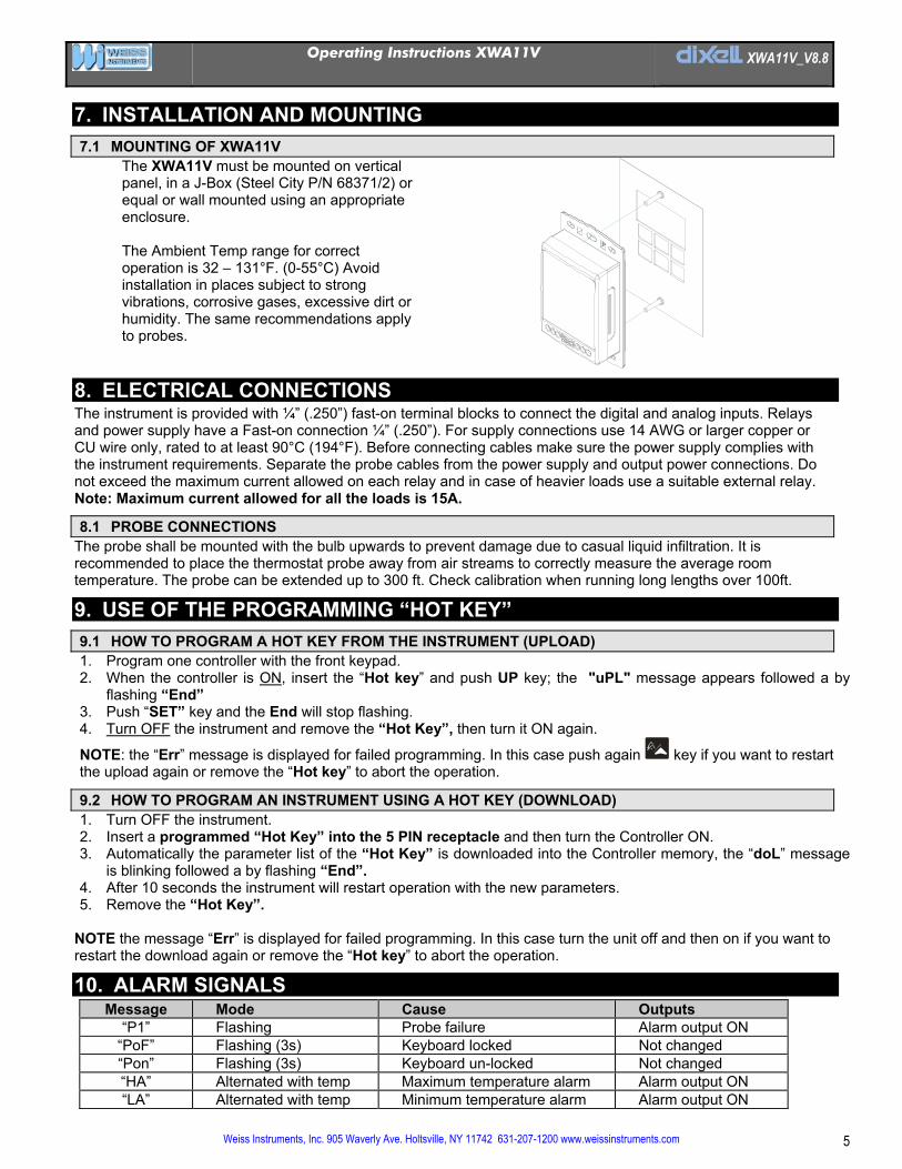
7.1 MOUNTING OF XWA11V The XWA11V must be mounted on vertical panel, in a J-Box (Steel City P/N 68371/2) or equal or wall mounted using an appropriate enclosure. The Ambient Temp range for correct operation is 32 – 131°F. (0-55°C) Avoid installation in places subject to strong vibrations, corrosive gases, excessive dirt or humidity. The same recommendations apply to probes.
8. ELECTRICAL CONNECTIONS The instrument is provided with ¼” (.250”) fast-on terminal blocks to connect the digital and analog inputs. Relays and power supply have a Fast-on connection ¼” (.250”). For supply connections use 14 AWG or larger copper or CU wire only, rated to at least 90°C (194°F). Before connecting cables make sure the power supply complies with the instrument requirements. Separate the probe cables from the power supply and output power connections. Do not exceed the maximum current allowed on each relay and in case of heavier loads use a suitable external relay. Note: Maximum current allowed for all the loads is 15A.
8.1 PROBE CONNECTIONS The probe shall be mounted with the bulb upwards to prevent damage due to casual liquid infiltration. It is recommended to place the thermostat probe away from air streams to correctly measure the average room temperature. The probe can be extended up to 300 ft. Check calibration when running long lengths over 100ft.
9. USE OF THE PROGRAMMING “HOT KEY”
9.1 HOW TO PROGRAM A HOT KEY FROM THE INSTRUMENT (UPLOAD) 1. Program one controller with the front keypad. 2. When the controller is ON, insert the “Hot key” and push UP key; the "uPL" message appears followed a by
flashing “End” 3. Push “SET” key and the End will stop flashing. 4. Turn OFF the instrument and remove the “Hot Key”, then turn it ON again.
NOTE: the “Err” message is displayed for failed programming. In this case push again key if you want to restart the upload again or remove the “Hot key” to abort the operation.
9.2 HOW TO PROGRAM AN INSTRUMENT USING A HOT KEY (DOWNLOAD) 1. Turn OFF the instrument. 2. Insert a programmed “Hot Key” into the 5 PIN receptacle and then turn the Controller ON. 3. Automatically the parameter list of the “Hot Key” is downloaded into the Controller memory, the “doL” message
is blinking followed a by flashing “End”. 4. After 10 seconds the instrument will restart operation with the new parameters. 5. Remove the “Hot Key”.
NOTE the message “Err” is displayed for failed programming. In this case turn the unit off and then on if you want to restart the download again or remove the “Hot key” to abort the operation.
10. ALARM SIGNALS Message Mode Cause Outputs
“P1” Flashing Probe failure Alarm output ON “PoF” Flashing (3s) Keyboard locked Not changed “Pon” Flashing (3s) Keyboard un-locked Not changed “HA” Alternated with temp Maximum temperature alarm Alarm output ON “LA” Alternated with temp Minimum temperature alarm Alarm output ON
Operating Instructions XWA11V dIXEL XWA11V_V8.8
Weiss Instruments, Inc. 905 Waverly Ave. Holtsville, NY 11742 631-207-1200 www.weissinstruments.com 6
“dA” Alternated with temp Door switch alarm Alarm output ON “EA” Alternated with temp External alarm Alarm output ON “PAn” Alternated with temp Serious external alarm Alarm output ON dEF Alternated with temp Defrost is running Not changed
The alarm message is displayed until the alarm condition is reset. Silencing buzzer
Once the alarm signal is detected the buzzer can be silenced by pressing the (UP) key.
10.1 ALARM RECOVERY Probe alarms: “P1” (probe1 faulty), automatically stop 10 seconds after the probe restarts normal operation. Check connections before replacing the probe. Temperature° alarms “HA” and “LA” automatically stop as soon as the thermometer temperature returns to normal operating values or when the defrost starts. Door switch alarm “dA” stops as soon as the door is closed. External alarms “EAL”, “BAL”, “dEF” stop as soon as the external digital input is disabled.
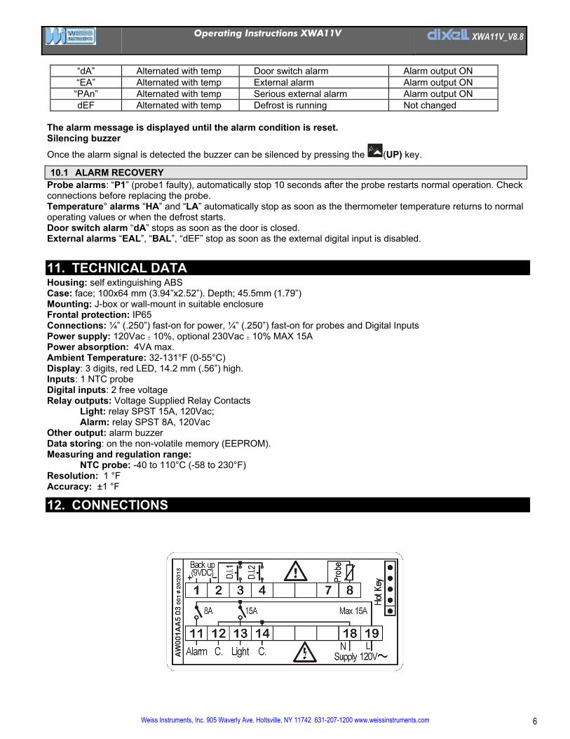
11. TECHNICAL DATA Housing: self extinguishing ABS Case: face; 100x64 mm (3.94”x2.52”). Depth; 45.5mm (1.79”) Mounting: J-box or wall-mount in suitable enclosure Frontal protection: IP65 Connections: ¼” (.250”) fast-on for power, ¼” (.250”) fast-on for probes and Digital Inputs Power supply: 120Vac 10%, optional 230Vac 10% MAX 15A Power absorption: 4VA max. Ambient Temperature: 32-131°F (0-55°C) Display: 3 digits, red LED, 14.2 mm (.56”) high. Inputs: 1 NTC probe Digital inputs: 2 free voltage Relay outputs: Voltage Supplied Relay Contacts
Light: relay SPST 15A, 120Vac; Alarm: relay SPST 8A, 120Vac
Other output: alarm buzzer Data storing: on the non-volatile memory (EEPROM). Measuring and regulation range:
NTC probe: -40 to 110°C (-58 to 230°F) Resolution: 1 °F Accuracy: ±1 °F
12. CONNECTIONS
Operating Instructions XWA11V dIXEL XWA11V_V8.8
Weiss Instruments, Inc. 905 Waverly Ave. Holtsville, NY 11742 631-207-1200 www.weissinstruments.com 7
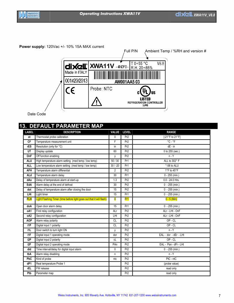
Power supply: 120Vac +/- 10% 15A MAX current Full P/N Ambient Temp / %RH and version #
Date Code
13. DEFAULT PARAMETER MAP LABEL DESCRIPTION VALUE LEVEL RANGE
ot Thermostat probe calibration 0 Pr2 [-21°F to 21°F]
CF Temperature measurement unit F Pr2 °C - °F
rES Resolution (only for °C) in Pr2 dE - in
UT Display update 60 Pr2 0 to 255 (sec.)
OnF Off function enabling y Pr2 n - Y
ALU High temperature alarm setting (med temp / low temp) 50 / 30 Pr1 ALL to 302° F
ALL Low temperature alarm setting (med temp / low temp) 30 / -20 Pr1 °-58 to ALU
AFH Temperature alarm differential 2 Pr2 1°F to 45°F
ALd Temperature alarm delay 30 Pr1 0 - 255 (min.)
dAo Delay of temperature alarm at start-up 1.3 Pr2 0.0 - 24.0 Hrs.
EdA Alarm delay at the end of defrost 30 Pr2 0 - 255 (min.)
dot Delay of temperature alarm after closing the door 15 Pr2 0 - 255 (min.)
LHt Light timer 15 Pr1 0 - 255 (min.)
FLH Light Flashing Timer (time before light goes out that it will flash) 0 Pr1 0 - 5 (Min)
doA Open door alarm delay 15 Pr1 0 - 255 (min.)
oA1 First relay configuration ALr Pr2 ALr - LHt - OnF
oA2 Second relay configuration LHt Pr2 ALr - LHt - OnF
AOP Alarm relay polarity CL Pr2 OP - CL
i1P Digital input 1 polarity CL Pr2 OP - CL
i1L Door switch to turn light ON y Pr2 n - Y
i1F Digital input 1 operating mode dor Pr2 EAL - dor - dEr - LHt
i2P Digital input 2 polarity cL Pr2 OP - CL
i2F Digital input 2 operating mode PAn Pr2 EAL - Pan - dFr - LHt
did Time interval/delay for digital input alarm 0 Pr2 0 - 255 (min.)
tbA Alarm relay disabling n Pr2 n - Y
PbC Kind of probe ntc Pr2 PtC - ntC
dP1 Real temperature Probe 1 Pr2 (probe value)
rEL FW release Pr2 read only
Ptb Parameter map Pr2 read only
Operating Instructions XWA11V dIXEL XWA11V_V8.8
Weiss Instruments, Inc. 905 Waverly Ave. Holtsville, NY 11742 631-207-1200 www.weissinstruments.com 8
14. PARAMETER LIST Ot Thermostat probe calibration: (-12.0 to12.0°C/ -21 to 21°F) allows to adjust possible offset of the thermostat probe. CF T measurement unit: °C = Celsius; °F = Fahrenheit. When the measurement unit is changed the Set Point and the values of some
parameters have to be modified. rES Resolution (for °C): (in = 1°C; dE = 0.1 °C) allows decimal point display. Ut Display update: The time delay of the Temperature readout (0 to 255 seconds) onF Off function enabling: n = off function disabled; y = off function enabled; ALU High Temp alarm setting: (ALL to 150°C or 302°F); when this temperature is reached and after the ALd delay time the HA alarm is
enabled. ALL Low Temp alarm setting: (- 50°C or -58°F to ALU) when this temperature is reached and after the ALd delay time, the LA alarm is
enabled. AFH Temp alarm differential: (0.1 to 25.5°C; 1 to 45°F) differential for temperature alarm Set Point and fan regulation Set Point, always a
positive value ALd Temp alarm delay: (0 to 255 min) time interval between the detection of an alarm condition and the corresponding alarm signaling. dAO Delay of Temp alarm at start-up: (0min to 23hrs, 50min) time interval between the detection of the temperature alarm condition after the
instrument power on and the alarm signaling. EdA Alarm delay at the end of defrosts: (0 to 255 min) Time interval between the detection of the temperature alarm condition at the end of
defrost and the alarm signaling. dot Delay of Temp alarm after closing the door: (0255 min) Time delay to signal the temperature alarm condition after closing the door. LHt Light timer: (0-255 min) Amount of time the light will stay on after pressing the light switch on the keyboard or after the door is closed.
FLH Light Flashing: (0-5 min) The light will “double flash” every 20 seconds during the FLH time period before turning off after the LHt time. This should only be enabled for use with incandesant or LED lighting!
doA Open door alarm delay:(0-255 min) delay between the detection of the open door condition and its alarm signaling: the flashing message “dA” is displayed.
oA1 First relay configuration: (14-15): ALr = alarm; LHt = light; onF = on/off relay oA2 Second relay configuration: (14-16): ALr = alarm; LHt = light; onF = on/off relay AOP Alarm relay polarity: cL = closing contacts (Relay will close on alarm giving voltage output);
oP = opening contacts (Relay will open on alarm no voltage output). i1P Digital input 1 polarity (1-2): CL : the digital input is activated by closing the contact; OP: the digital input is activated by opening the contact i1L Door switch to turn light ON(1-2): (y / n) To turn the light ON automatically when the door is open. The light will turn off based on LHt .
Keyboard switch must be turned ON first. i1F Digital input 1 operating mode(1-2): EAL = external alarm; dor = door switch; dFr = A defrost is running; LHt = keep light ON (signal
from occupancy sensor) override LHt.; i2P Digital input 2 polarity (1-3): CL : the digital input is activated by closing the contact; OP: the digital input is activated by opening the contact i2F Digital input 2 operating mode: configure the digital input function: EAL = External alarm; PAn =Panic alarm; dFr = A defrost is running; (need external CT’s) LHt = Keep light ON (signal from occupancy sensor) overrides LHt. did Time interval/delay for digital input alarm:(0-255 min.) If I2F=EAL or PAn (external alarms), “did” parameter defines the time delay
between the detection and the successive signaling of the alarm. tbA Alarm relay & Buzzer disabling: (y ; no) Pbc Type of probe (PTC, NTC) dP1 Probe 1 Temperature rEL Software release for internal use. Ptb Parameter table code: read only.
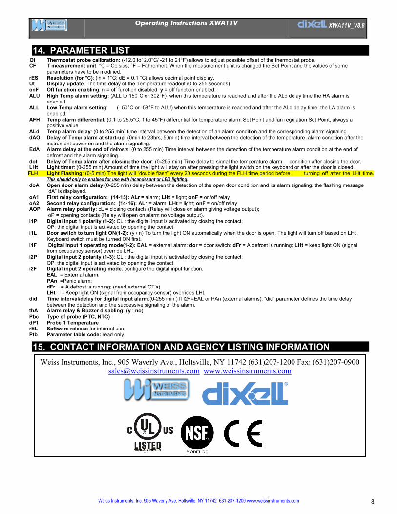
15. CONTACT INFORMATION AND AGENCY LISTING INFORMATION
Weiss Instruments, Inc., 905 Waverly Ave., Holtsville, NY 11742 (631)207-1200 Fax: (631)207-0900 [email protected] www.weissinstruments.com
F