Embed Size (px)
Citation preview

Soil Mechanics XVI. SHEAR STRENGTH OF SOIL

Soil Mechanics XVI.1. SHEAR STRENGTH OF SOIL
Mohr-Coulomb Failure Criteria

DEFINITION
The maximum or ultimate value of shear stress that can be mobilized
within a soil mass without failure taking place.
The internal resistance per unit area that the soil mass can offer to
resist failure and sliding along any plane inside it.
APPLICATION
Shear Strength can be used for calculating :
– Bearing Capacity of Soil
– Slope Stability
– Lateral Pressure
Shear Strength of Soil

VERTICAL SLOPE RETAINING EARTH WALL
EMBANKMENT LANDSLIDE
GLOBAL FAILURE OF
SHALLOW FOUNDATION
LOCAL FAILURE OF
SHALLOW FOUNDATION

Embankment Strip footing
Soils generally fail in SHEAR
At failure, shear stress along the failure surface (mobilized shear
resistance) reaches the shear strength.
Failure surface
Mobilized shear resistance
Shear Failure in Soils

Retaining wall
Failure surface
Mobilized shear resistance
Soils generally fail in SHEAR
Shear Failure in Soils
At failure, shear stress along the failure surface (mobilized shear
resistance) reaches the shear strength.

At failure, shear stress along the failure surface () reaches the shear
strength (f).
• The soil grains slide over each other along the failure surface.
• No crushing of individual grains.
Shear Failure Mechanism Embankment

FIELD INFLUENCE FACTOR Soil condition : void ratio, particle shape and size
Soil type : Gravel, Sand, Silt, Clay, etc. Water content (especially for clay)
Type of load and its rate
Anisotropic condition
LABORATORY Test method
Sample disturbance
Water content
Strain rate
Shear Strength of Soil
PARAMETER
Cohesion (c)
Internal Friction Angle ()
CONDITION
Total (c and )
Effective (c’ and ’)
GENERAL EQUATION (MOHR-COULOMB)
= c + n tan or = c’ + (n – u)tan’
Shear Strength of Soil

COHESIVE SOIL
Has cohesion (c)
Example : Clay, Silt
COHESIONLESS SOIL
Only has internal friction angle () ; c = 0
Example : Sand, Gravel
Shear Strength of Soil Soil Type
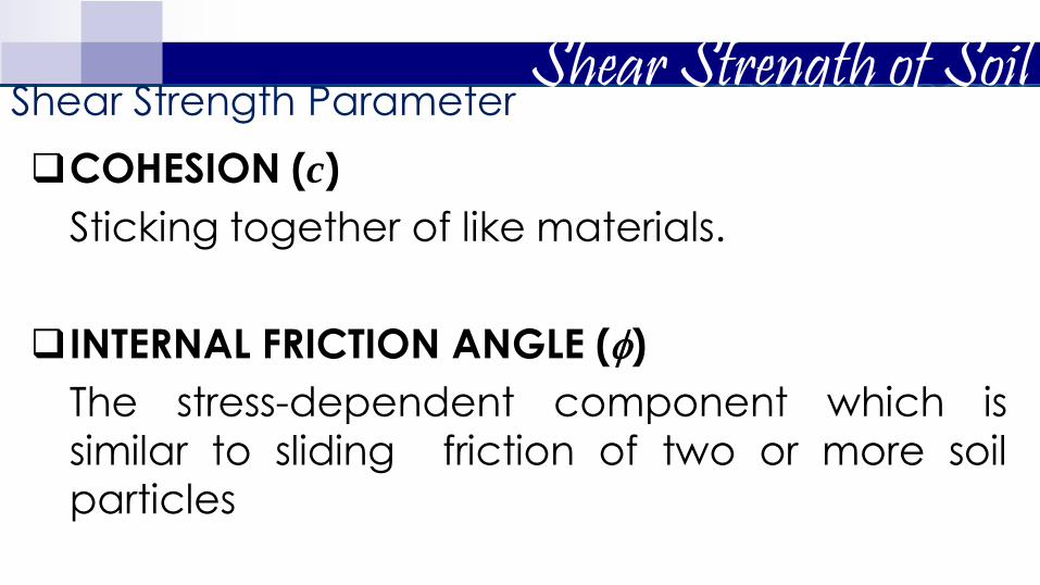
COHESION (c)
Sticking together of like materials.
INTERNAL FRICTION ANGLE ()
The stress-dependent component which is similar to sliding friction of two or more soil particles
Shear Strength of Soil Shear Strength Parameter
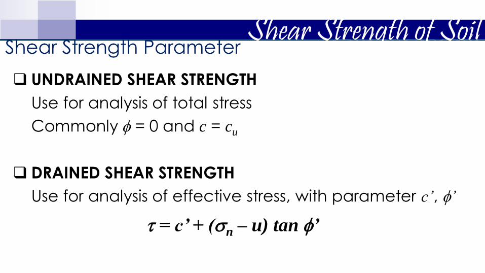
UNDRAINED SHEAR STRENGTH
Use for analysis of total stress
Commonly = 0 and c = cu
DRAINED SHEAR STRENGTH
Use for analysis of effective stress, with parameter c’, ’
= c’ + (n – u) tan ’
Shear Strength of Soil Shear Strength Parameter

Shear Strength of Soil Mohr Circle of Stresses
In soil testing, cylindrical samples are commonly used in which radial
and axial stresses act on principal planes. The vertical plane is usually
the minor principal plane whereas the horizontal plane is the principal plane. The radial stress (𝜎𝑟) is the minor principal stress (𝜎3), and the
axial stress (𝜎𝑎) is the major principal stress (𝜎1).

Shear Strength of Soil Mohr Circle of Stresses
To visualize the normal and shear stresses acting on any plane within
the soil sample, a graphical representation of stresses called the Mohr
circle is obtained by plotting the principal stresses. The sign
convention in the construction is to consider compressive stresses as
positive and angles measured counter-clockwise also positive.
Shear Strength of Soil Mohr-Coulomb Failure Criteria
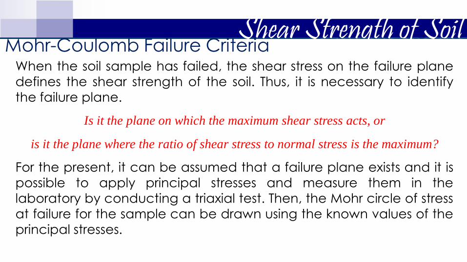
When the soil sample has failed, the shear stress on the failure plane
defines the shear strength of the soil. Thus, it is necessary to identify
the failure plane.
Is it the plane on which the maximum shear stress acts, or
is it the plane where the ratio of shear stress to normal stress is the maximum?
For the present, it can be assumed that a failure plane exists and it is
possible to apply principal stresses and measure them in the
laboratory by conducting a triaxial test. Then, the Mohr circle of stress
at failure for the sample can be drawn using the known values of the
principal stresses.

Shear Strength of Soil Mohr-Coulomb Failure Criteria
If data from several tests, carried out on different samples up to
failure is available, a series of Mohr circles can be plotted. It is
convenient to show only the upper half of the Mohr circle. A line
tangential to the Mohr circles can be drawn, and is called the Mohr-
Coulomb failure envelope.

f is the maximum shear stress the soil can take without failure, under
normal stress of .
c
Cohesion Friction angle
f
Shear Strength of Soil Total Stress Analysis
𝜏𝑓 = 𝑐 + 𝜎 tan ϕ

f is the maximum shear stress the soil can take without failure, under
normal effective stress of ’.
’
c’
’ Effective
cohesion Effective
friction angle f
’
(u = pore water pressure)
Shear Strength of Soil Effective Stress Analysis
𝜏𝑓 = 𝑐′ + 𝜎′ tan ϕ′ 𝜎′ = 𝜎 − 𝑢

𝜏𝑓 = 𝑐′ + 𝜎′ tan ϕ′
Shear strength consists of two components: cohesive and
frictional.
’
f ’
'
c’ c’
cohesive component
’ tan’
frictional component
Shear Strength of Soil Mohr-Coulomb Failure Criteria

Soil elements at different locations
Failure surface
X X
X ~ failure
Y Y
Y ~ stable
’
Shear Strength of Soil Mohr-Coulomb Failure Criteria
𝜏𝑓 = 𝑐′ + 𝜎′ tan ϕ′

Y
c
c
c Initially, Mohr circle is a point
c+
The soil element does not fail if
the Mohr circle is contained
within the envelope GL
Shear Strength of Soil Mohr-Coulomb Failure Criteria
’

c
GL
As loading progresses, Mohr
circle becomes larger…
…and finally failure occurs
when Mohr circle touches
the envelope
Shear Strength of Soil Mohr-Coulomb Failure Criteria
Y
c
c
’

= X
v’
h’ X
u
u +
v’ h’ u v h
X
v
h
σ or σ’
Shear Strength of Soil Total vs Effective Stress Analysis
ϕ’
c’ c
ϕ If X is on failure,

X
𝜎𝑣′
= 𝜎1′
X is on failure
σ’ ϕ’ c’
2'sin
2'cot'
'
3
'
1
'
3
'
1
c
Therefore,
Shear Strength of Soil Mohr-Coulomb Failure Criterion with Mohr Circle of Stress
𝜎ℎ′
= 𝜎3′
(𝜎1′ − 𝜎3
′)
2
(𝜎1′ + 𝜎3
′)
2
𝑐′ cot ∅
𝜎3′ 𝜎1
′

2'sin
2'cot'
'
3
'
1
'
3
'
1
c
'cos'2'sin'
3
'
1
'
3
'
1 c
'cos'2'sin1'sin1 '
3
'
1 c
'sin1
'cos'2
'sin1
'sin1'
3
'
1
c
2
'45tan'2
2
'45tan2'
3
'
1
c
Shear Strength of Soil Mohr-Coulomb Failure Criterion with Mohr Circle of Stress

Shear Strength of Soil Inclination of the Plane of Failure Caused by Shear
Failure → when shear stress on a plane reaches 𝜏𝑓 line
→ determine inclination (θ) of failure plane with major and minor
principal planes

For the soil element shown, determine the normal and shear stresses
on a plane inclined at 35° from the
horizontal axis.
Shear Strength of Soil Example 1

Foil the soil element shown,
determine and .
Shear Strength of Soil Example 2

Soil Mechanics XVI.2. SHEAR STRENGTH OF SOIL
Determination of Shear Strength Parameters

LABORATORY TESTS
Direct Shear Test (DST)
Triaxial (TX) Shear Test (UU, CU, CD)
Unconfined Compression Test (UCT)
FIELD INVESTIGATION
Vane Shear Test (VST)
PARAMETER CORRELATIONS
Cone Penetration Test (SCPT, DCPT)
Standard Penetration Test (SPT) N-Value
California Bearing Ratio (CBR)
Shear Strength of Soil

Other laboratory tests include, direct simple
shear test, torsional ring shear test, plane strain
triaxial test, laboratory vane shear test,
laboratory fall cone test
Laboratory tests on specimens
taken from representative
undisturbed samples
Field tests
Most common laboratory tests to determine the shear strength parameters are, 1.Direct shear test 2.Triaxial shear test
1. Vane shear test 2. Torvane 3. Pocket penetrometer 4. Fall cone 5. Pressuremeter 6. Static cone penetrometer 7. Standard penetration test
Shear strength parameters of soils

Field conditions
z vc
vc
hc hc
Before construction
A representative soil sample z vc +
hc hc
After and during construction
vc +
Shear Strength of Soil Laboratory Tests
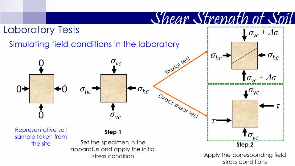
Simulating field conditions in the laboratory
Step 1
Set the specimen in the
apparatus and apply the initial
stress condition
σvc
σvc
σhc σhc
Representative soil
sample taken from
the site
0
0 0
0
Step 2
Apply the corresponding field
stress conditions
σvc + Δσ
σhc σhc
σvc + Δσ
σvc
σvc
Shear Strength of Soil Laboratory Tests

Shear Strength of Soil Direct Shear Test
The test is carried out on a soil
sample confined in a metal box
of square cross-section which is
split horizontally at mid-height. A
small clearance is maintained
between the two halves of the
box. The soil is sheared along a
predetermined plane by moving
the top half of the box relative to
the bottom half. The box is usually square in plan of size 60 mm x 60
mm. A typical shear box is shown.

Shear Strength of Soil Direct Shear Test
If the soil sample is fully or partially saturated, perforated metal plates
and porous stones are placed below and above the sample to allow
free drainage. If the sample is dry, solid metal plates are used. A load
normal to the plane of shearing can be applied to the soil sample
through the lid of the box.
Tests on sands and gravels can be performed quickly, and are
usually performed dry as it is found that water does not significantly
affect the drained strength. For clays, the rate of shearing must be
chosen to prevent excess pore pressures building up.

Shear Strength of Soil Direct Shear Test
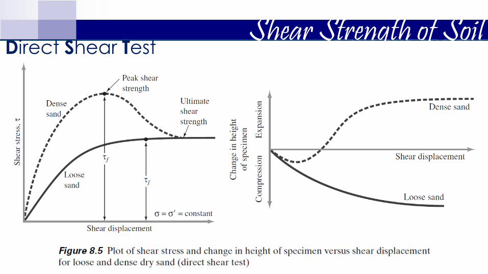
As a vertical normal load is applied to the sample, shear stress is
gradually applied horizontally, by causing the two halves of the box
to move relative to each other. The shear load is measured together
with the corresponding shear displacement. The change of thickness
of the sample is also measured.
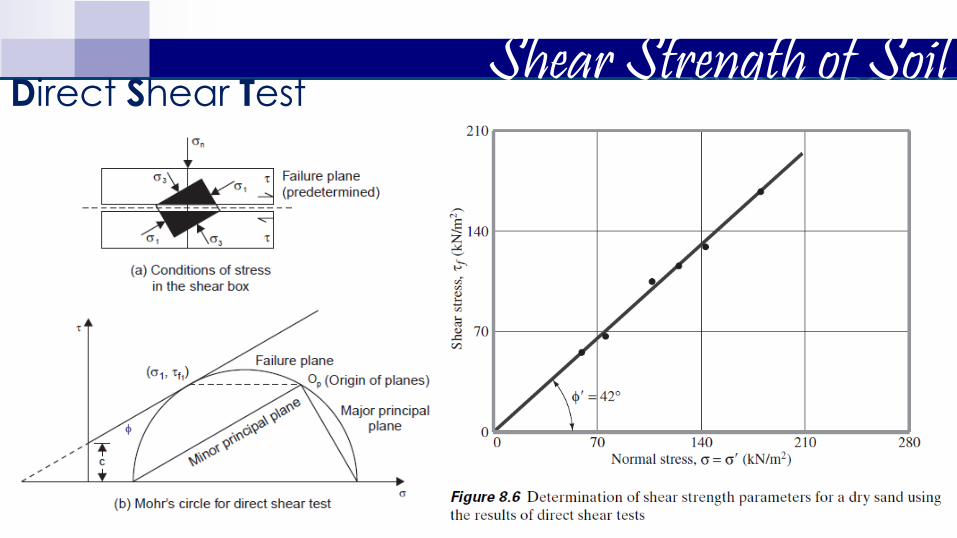
A number of samples of the soil are tested each under different
vertical loads and the value of shear stress at failure is plotted against
the normal stress for each test. Provided there is no excess pore
water pressure in the soil, the total and effective stresses will be
identical. From the stresses at failure, the failure envelope can be
obtained.

Shear Strength of Soil Direct Shear Test
Specimen is square or
circular
Box splits horizontally in
halves
Normal force applied on top
shear box
Shear force is applied to
move one half of the box
relative to the other (to fail
specimen)

Shear Strength of Soil Direct Shear Test
Shear force applied in equal
increments until failure
Failure plane is predetermined
(horizontal)
Horizontal deformation & ΔH is
measured under each load.
Stress-controlled

Shear Strength of Soil Direct Shear Test
Constant rate of shear
displacement
Restraining shear force is
measured
Volume changed (ΔH)
Gives ultimate & residual
shear strength
Strain-controlled

Shear Strength of Soil Direct Shear Test
For a given test on dry soil, the normal stress can be calculated as,
The resisting shear stress for any shear displacement can be
calculates as,
Shear Strength of Soil Direct Shear Test
Shear Strength of Soil Direct Shear Test

Shear Strength of Soil Direct Shear Test
The test has several advantages:
It is easy to test sands and gravels.
Large samples can be tested in large shear boxes, as small samples can give misleading results due to imperfections such as fractures and fissures, or may not be truly representative.
Samples can be sheared along predetermined planes, when the shear strength along fissures or other selected planes are needed.

Shear Strength of Soil Direct Shear Test
The disadvantages of the test include:
The failure plane is always horizontal in the test, and this may not be the weakest plane in the sample. Failure of the soil occurs progressively from the edges towards the centre of the sample.
There is no provision for measuring pore water pressure in the shear box and so it is not possible to determine effective stresses from undrained tests.
The shear box apparatus cannot give reliable undrained strengths because it is impossible to prevent localised drainage away from the shear plane.

Shear Strength of Soil

Shear Strength of Soil Triaxial Shear Test
The triaxial test is carried out in a
cell on a cylindrical soil sample
having a length to diameter ratio of
2. The usual sizes are 76 mm x 38 mm
and 100 mm x 50 mm. Three principal
stresses are applied to the soil
sample, out of which two are applied
water pressure inside the confining
cell and are equal. The third principal
stress is applied by a loading ram
through the top of the cell and is
different to the other two principal
stresses. A typical triaxial cell is shown.

Shear Strength of Soil Triaxial Shear Test
The soil sample is placed inside a rubber sheath which is sealed to a
top cap and bottom pedestal by rubber O-rings. For tests with pore
pressure measurement, porous discs are placed at the bottom, and
sometimes at the top of the specimen. Filter paper drains may be
provided around the outside of the specimen in order to speed up
the consolidation process. Pore pressure generated inside the
specimen during testing can be measured by means of pressure
transducers.
Shear Strength of Soil Triaxial Shear Test
The triaxial compression test consists of two stages:
First stage: In this, a soil sample is set in the triaxial cell and
confining pressure is then applied.
Second stage: In this, additional axial stress (also called deviator
stress) is applied which induces shear stresses in the sample. The
axial stress is continuously increased until the sample fails.
During both the stages, the applied stresses, axial strain, and pore
water pressure or change in sample volume can be measured.

Shear Strength of Soil Triaxial Shear Test
The triaxial compression test consists of two stages:
Stage 1 Stage 2 Consolidation Stage Shearing Stage

Shear Strength of Soil Triaxial Shear Test

Shear Strength of Soil Triaxial Shear Test
Test Types
There are several test variations, and those used mostly in practice are:
Consolidated-Drained (CD) test: This is similar to CU test except that as
deviator stress is increased, drainage is permitted. The rate of loading
must be slow enough to ensure no excess pore water pressure develops.
CU Consolidated-Undrained (CU) test: In this, drainage is allowed during
cell pressure application. Then without allowing further drainage, deviator
stress is increased keeping cell pressure constant.
Unconsolidated-Undrained (UU) test: In this, cell pressure is applied without
allowing drainage. Then keeping cell pressure constant, deviator stress is
increased to failure without drainage.

Shear Strength of Soil Triaxial Shear Test
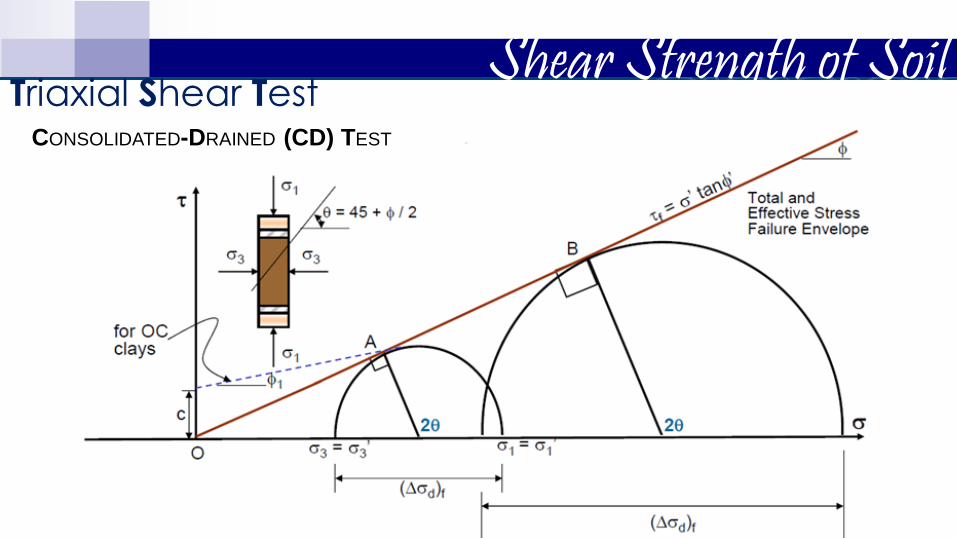
CONSOLIDATED-DRAINED (CD) TEST
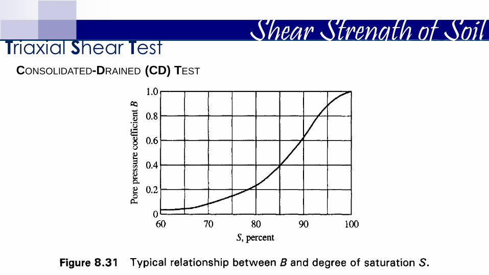
𝐵 =𝑢𝑐
𝜎3 Skempton’s pore water pressure parameter (B ~ 1.0 for saturated soils)
End of consolidation stage 𝑢𝑐 = 0.
Application of deviator stress, ∆𝜎𝑑:
For drained test ∆𝜎𝑑 is increased slowly, while the drainage valve is kept open,
and any excess pore water pressure generated by ∆𝜎𝑑 is allowed to dissipate.
(ΔV can be measured by measuring amount outflow-water, since S = 100%)
CD test: excess pore water pressure completely dissipated 𝜎3 = 𝜎3′ .
Specimen is subjected to confining stress 𝜎3 all around.
As a result the pore water pressure of the sample increases by 𝑢𝑐.
If the valve is opened at this point the 𝑢𝑐 will dissipate and sample will consolidate (ΔV decreases under 𝜎3)
Stage 1
Stage 2
Shear Strength of Soil Triaxial Shear Test
CONSOLIDATED-DRAINED (CD) TEST

Shear Strength of Soil Triaxial Shear Test
At failure, total axial stress is same with effective axial stress.
𝜎1 = 𝜎1′=𝜎3
′ + (∆𝜎𝑑)𝑓
𝜎1′→ major principal effective stress at failure
𝜎3′→ minor principal effective stress at failure
Conduct other triaxial (CD) tests under different confining pressure 𝜎3 and obtain the corresponding 𝜎1
′ at failure and plot the Mohr’s circle for each test.
CONSOLIDATED-DRAINED (CD) TEST
Shear Strength of Soil Triaxial Shear Test
CONSOLIDATED-DRAINED (CD) TEST

Shear Strength of Soil Triaxial Shear Test
Ᾱ =∆𝑢𝑑
∆𝜎𝑑
End of consolidation stage ∆𝑢𝑐 = 0 (and close valves).
Loose sand and NC clay → ∆𝑢𝑑 increases with strain
Dense sand and OC clay → ∆𝑢𝑑 increases with strain up to a certain point and drops and
becomes negative (due to dilation of soil)
Consolidation of S = 100% sample under confining stress 𝜎3 and allow 𝑢𝑐 to
dissipate.
Drainage valve is closed after complete consolidation (𝑢𝑐 = 0)
Skempton’s pore water pressure parameter
CONSOLIDATED-UNDRAINED (CU) TEST
Stage 1
Stage 2 Deviator stress ∆𝜎𝑑 is applied and increased to failure.
Excess pore water pressure ∆𝑢𝑑 is developed (due to no drainage).

Shear Strength of Soil Triaxial Shear Test
Total and effective principal stresses are not the same.
At failure, measure (∆𝜎𝑑)𝑓 and (∆𝑢𝑑)𝑓.
Major principal stress at failure is obtained as:
Total → 𝜎1 = 𝜎3 + (∆𝜎𝑑)𝑓
Effective → 𝜎1′ = 𝜎1 − (∆𝑢𝑑)𝑓
Minor principal stress at failure is obtained as:
Total → 𝜎3
Effective → 𝜎3′ = 𝜎3 − (∆𝑢𝑑)𝑓
CONSOLIDATED-UNDRAINED (CU) TEST

Shear Strength of Soil Triaxial Shear Test
CONSOLIDATED-UNDRAINED (CU) TEST

Shear Strength of Soil Triaxial Shear Test
CONSOLIDATED-UNDRAINED (CU) TEST

Shear Strength of Soil Triaxial Shear Test
CONSOLIDATED-UNDRAINED (CU) TEST

Shear Strength of Soil Triaxial Shear Test
Drainage in both stages is not allowed.
Therefore application of 𝜎3 → 𝑢𝑐 = 𝐵𝜎3 (in Stage 1)
And application of ∆𝜎𝑑 → ∆𝑢𝑑= Ᾱ∆𝜎𝑑 (in Stage 2)
Total pore water pressure, 𝑢 = 𝑢𝑐 + ∆𝑢𝑑 → 𝑢 = 𝐵𝜎3 + Ᾱ∆𝜎𝑑= 𝐵𝜎3 + Ᾱ 𝜎1 − 𝜎3
It can be seen that tests conducted with different 𝜎3 results in the same (∆𝜎𝑑)𝑓 ,
resulting in Mohr’s circle with same radius.
UNCONSOLIDATED-UNDRAINED (UU) TEST

Shear Strength of Soil Triaxial Shear Test
UNCONSOLIDATED-UNDRAINED (UU) TEST

Test Condition
Stage 1 Stage 2
Unconsolidated
Undrained (UU)
Apply confining pressure 3 while the drainage line from the specimen is kept closed (drainage is not
permitted), then the initial pore water pressure (u=uc) is not equal to zero
Apply an added stress d at axial direction. The drainage line from the specimen is still kept closed (drainage is not permitted) (u=Δud0). At failure state
d=(d)f ; pore water pressure u=uf=uc+Δud(f)
Consolidated
Undrained (CU)
Apply confining pressure 3 while the drainage line
from the specimen is opened (drainage is
permitted), then the initial pore water pressure (u=uc) is equal to zero
Apply an added stress d at axial direction. The drainage line from the specimen is kept closed (drainage is not permitted) (u=Δud0). At failure state
d=(d)f ; pore water pressure u=uf=uc+Δud(f)=Δud(f)
Consolidated
Drained (CD)
Apply confining pressure 3 while the drainage line from the specimen is opened (drainage is
permitted), then the initial pore water pressure (u=uc) is equal to zero
Apply an added stress d at axial direction. The drainage line from the specimen is opened (drainage is permitted) so the pore water pressure (u=Δud) is
equal to zero. At failure state d=(d)f; pore water pressure u=uf=uc+Δud(f)=0
3
3
3
3
Shear Strength of Soil Triaxial Shear Test

Shear Strength of Soil Triaxial Shear Test
Significance of Triaxial Testing
The first stage simulates in the laboratory the in-situ condition that soil at different depths is subjected to different effective stresses. Consolidation will occur if the pore water pressure which develops upon application of confining pressure is allowed to dissipate. Otherwise the effective stress on the soil is the confining pressure (or total stress) minus the pore water pressure which exists in the soil.
During the shearing process, the soil sample experiences axial strain, and either volume change or development of pore water pressure occurs. The magnitude of shear stress acting on different planes in the soil sample is different. When at some strain the sample fails, this limiting shear stress on the failure plane is called the shear strength.

Shear Strength of Soil Triaxial Shear Test
The triaxial test has many advantages over the direct shear test:
• The soil samples are subjected to uniform stresses and strains.
• Different combinations of confining and axial stresses can be applied.
• Drained and undrained tests can be carried out.
• Pore water pressures can be measured in undrained tests.
• The complete stress-strain behaviour can be determined.
Shear Strength of Soil Triaxial Shear Test
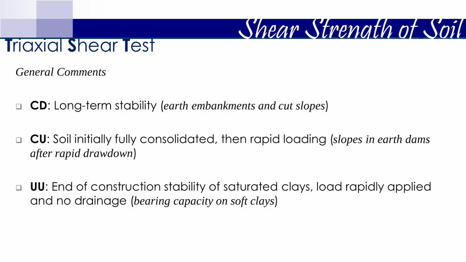
General Comments
CD: Long-term stability (earth embankments and cut slopes)
CU: Soil initially fully consolidated, then rapid loading (slopes in earth dams
after rapid drawdown)
UU: End of construction stability of saturated clays, load rapidly applied
and no drainage (bearing capacity on soft clays)
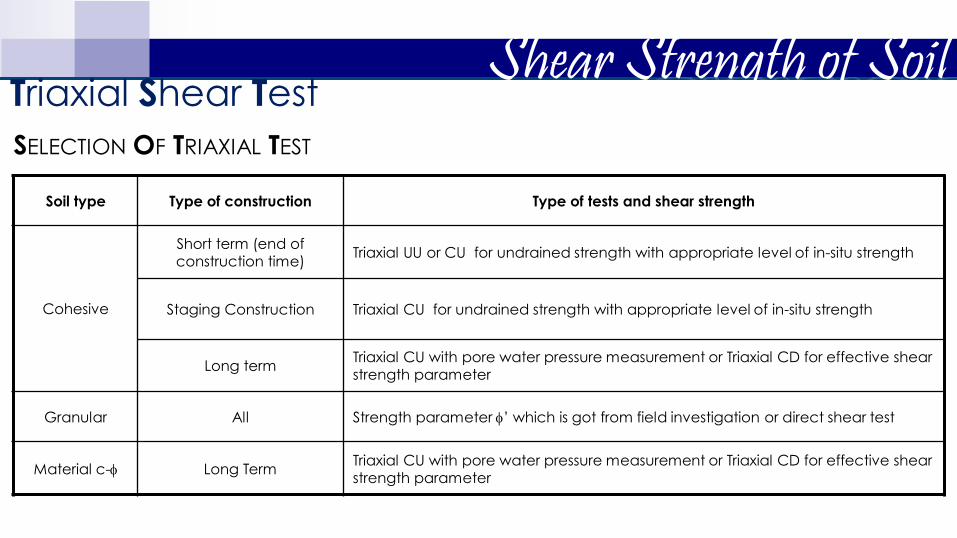
SELECTION OF TRIAXIAL TEST
Soil type Type of construction Type of tests and shear strength
Cohesive
Short term (end of construction time)
Triaxial UU or CU for undrained strength with appropriate level of in-situ strength
Staging Construction Triaxial CU for undrained strength with appropriate level of in-situ strength
Long term Triaxial CU with pore water pressure measurement or Triaxial CD for effective shear strength parameter
Granular All Strength parameter ’ which is got from field investigation or direct shear test
Material c- Long Term Triaxial CU with pore water pressure measurement or Triaxial CD for effective shear strength parameter
Shear Strength of Soil Triaxial Shear Test

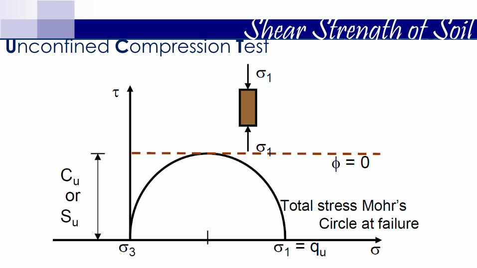
Shear Strength of Soil Unconfined Compression Test A type of unconsolidated-undrained triaxial test
For clayey samples (cohesive soils)
Confining pressure 𝜎3= 0
Axial load 𝜎1 applied to fail the sample (relatively rapid)
At failure (𝜎3)𝑓 = 0 and (𝜎1)𝑓 = major principal stress
Therefore undrained shear strength is independent of confining
pressure
𝜏1 =𝜎1
2=
𝑞𝑢
2= 𝑐𝑢 𝑜𝑟 𝑠𝑢
where 𝑞𝑢 is the unconfined compressive strength, and 𝑐𝑢(𝑜𝑟 𝑠𝑢) is the
undrained shear strength
Shear Strength of Soil Unconfined Compression Test

Shear Strength of Soil Unconfined Compression Test

Direct shear tests were performed on a dry, sandy soil. The size of the specimen was 50 mm x 50 mm x 20 mm. Tests results were as given in the
table. Find the shear stress parameters.
Test No. Normal Force
(N) Shear Force at
Failure (N)
1 90 54
2 135 82.35
3 315 189.5
4 450 270.5
Problem Set Problem 1
13
Normal Stress, σ
(kPa)
Shear Stress at Failure, τ
(kPa)
36 21.6
54 32.9
126 75.8
180 108.2

For a normally consolidated clay, these are the results of a drained
triaxial test:
chamber confining pressure = 112 kPa
deviator stress at failure = 175 kPa
2.1 Find the angle of internal friction, ø’.
2.2 Determine the angle θ that the failure plane makes with the major principal
plane.
2.3 Find the normal stress σ’ and the shear stress τf on the failure plane.
2.4 Determine the effective normal stress on the plane of maximum shear stress.
Problem Set Problem 2
13
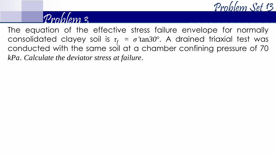
Problem Set Problem 3
13
The equation of the effective stress failure envelope for normally consolidated clayey soil is τf = σ’tan30°. A drained triaxial test was
conducted with the same soil at a chamber confining pressure of 70 kPa. Calculate the deviator stress at failure.

The maximum principal stress that causes failure of a cohesive soil specimen in a triaxial test is equal to 220 kPa. The angle of internal
friction is equal to 25°. If the deviator stress at failure is equal to140 kPa. 4.1 Compute the confining chamber pressure .
4.2 Compute the cohesion.
4.3 Compute the shearing stress at failure.
Problem Set Problem 4
13

An unconsolidated-undrained test was conducted on a saturated clay. The cell pressure was 200 kPa and failure occurred under a
deviatoric stress of 220 kPa. 5.1 Determine the angle of shearing resistance.
5.2 Determine the maximum principal stress at failure.
5.3 Determine the undrained shear strength.
Problem Set Problem 5
13
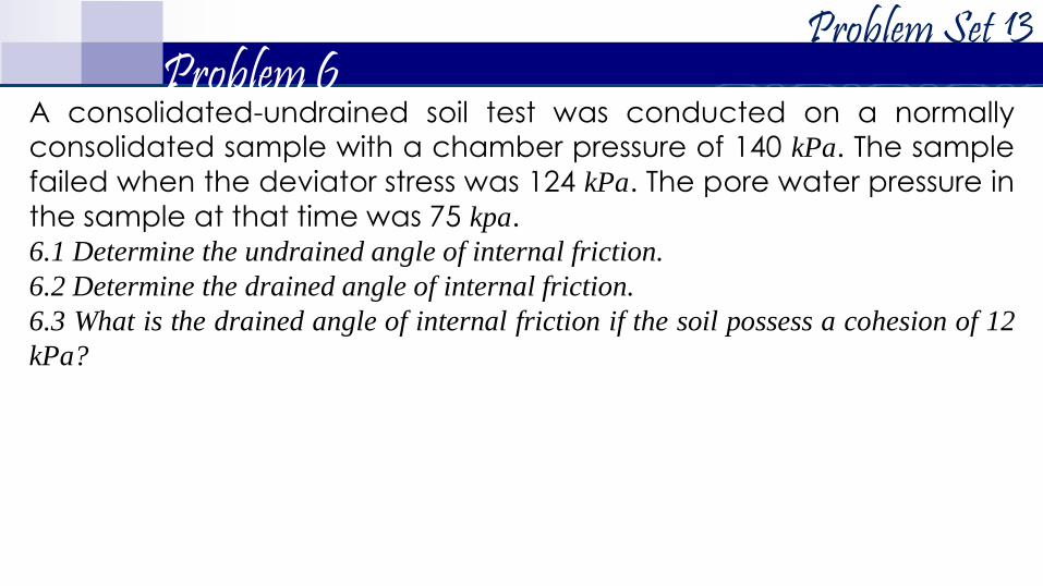
A consolidated-undrained soil test was conducted on a normally consolidated sample with a chamber pressure of 140 kPa. The sample
failed when the deviator stress was 124 kPa. The pore water pressure in
the sample at that time was 75 kpa. 6.1 Determine the undrained angle of internal friction.
6.2 Determine the drained angle of internal friction.
6.3 What is the drained angle of internal friction if the soil possess a cohesion of 12
kPa?
Problem Set Problem 6
13
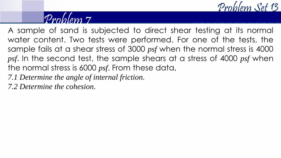
A sample of sand is subjected to direct shear testing at its normal
water content. Two tests were performed. For one of the tests, the sample fails at a shear stress of 3000 psf when the normal stress is 4000
psf. In the second test, the sample shears at a stress of 4000 psf when
the normal stress is 6000 psf. From these data, 7.1 Determine the angle of internal friction.
7.2 Determine the cohesion.
Problem Set Problem 7
13

We have the results of two drained triaxial tests on a saturated clay:
Determine the shear strength parameters.
Problem Set Problem 8
13
Specimen No. σf, kPa (Δσd)f, kPa
1 70 173
2 105 235
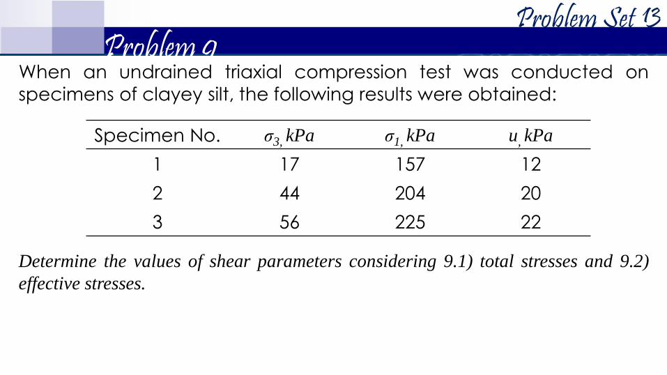
When an undrained triaxial compression test was conducted on
specimens of clayey silt, the following results were obtained:
Determine the values of shear parameters considering 9.1) total stresses and 9.2)
effective stresses.
Problem Set Problem 9
13
Specimen No. σ3, kPa σ1, kPa u, kPa
1 17 157 12
2 44 204 20
3 56 225 22
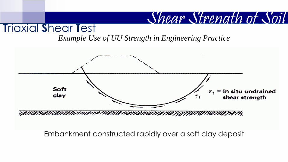
Embankment constructed rapidly over a soft clay deposit
Example Use of UU Strength in Engineering Practice
Shear Strength of Soil Triaxial Shear Test

Example Use of UU Strength in Engineering Practice
Large earth dam constructed rapidly with
no change in water content of clay core
Shear Strength of Soil Triaxial Shear Test
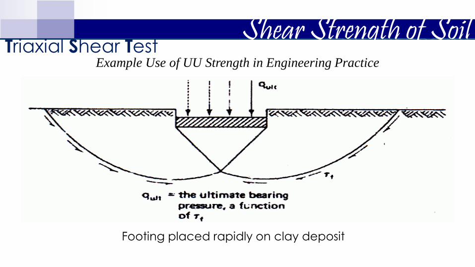
Footing placed rapidly on clay deposit
Example Use of UU Strength in Engineering Practice
Shear Strength of Soil Triaxial Shear Test

Embankment raised (2) subsequent to
consolidation under its original height (1)
Example Use of CU Strength in Engineering Practice
Shear Strength of Soil Triaxial Shear Test

Rapid drawdown behind an earth dam
No drainage of the core. Reservoir level falls from 1 2
Example Use of CU Strength in Engineering Practice
Shear Strength of Soil Triaxial Shear Test

Rapid construction of an embankment on a natural slope
Example Use of CU Strength in Engineering Practice
Shear Strength of Soil Triaxial Shear Test

Embankment constructed very slowly, in layers,
over a soft clay deposit
Example Use of CD Strength in Engineering Practice
Shear Strength of Soil Triaxial Shear Test
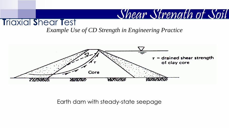
Earth dam with steady-state seepage
Example Use of CD Strength in Engineering Practice
Shear Strength of Soil Triaxial Shear Test

Excavation or natural slope in clay
Example Use of CD Strength in Engineering Practice
Shear Strength of Soil Triaxial Shear Test

CU with pore water
pressure measurement
SELECTION OF SHEAR STRENGTH PARAMETER
Shear Strength of Soil Triaxial Shear Test
![Shear Strength Testing Fixture - CORE · PDF fileShear strength is defined as the maximum load, applied perpendicularly, that a material can withstand before fracture [1]. This means](https://img.pdfslide.us/doc/110x75/5aa58c9d7f8b9a517d8d627d/shear-strength-testing-fixture-core-strength-is-defined-as-the-maximum-load-applied.jpg)