Embed Size (px)
Citation preview
Xtreme Power Conversion® Corporation
Xtreme Performance Rack Tower Series
(XPRT-6kVA/10kVA)
User’s & Installation Manual
XPRT-6kVA, XPRT-10kVA USER’S MANUAL UNINTERRUPTIBLE POWER SUPPLY (UPS)
Xtreme Power Conversion® (XPC) Corporation Page 2
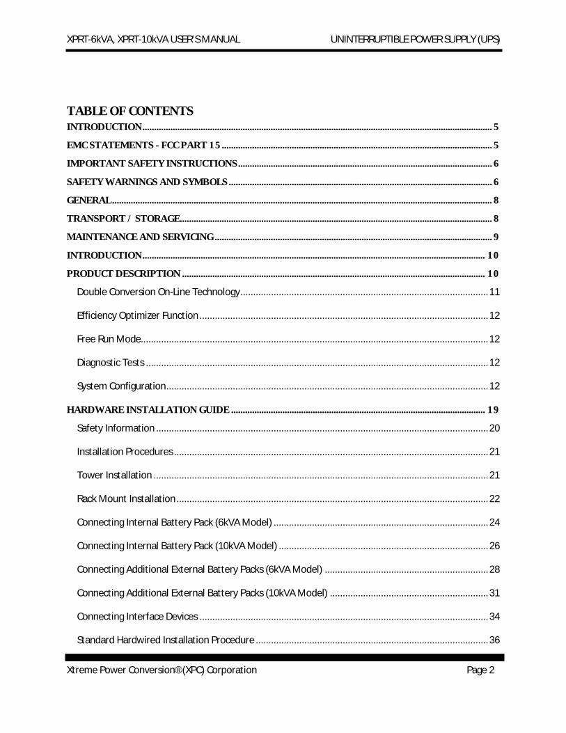
TABLE OF CONTENTS INTRODUCTION ...................................................................................................................................................... 5
EMC STATEMENTS - FCC PART 15 .................................................................................................................... 5
IMPORTANT SAFETY INSTRUCTIONS ............................................................................................................. 6
SAFETY WARNINGS AND SYMBOLS ................................................................................................................. 6
GENERAL ................................................................................................................................................................... 8
TRANSPORT / STORAGE ...................................................................................................................................... 8
MAINTENANCE AND SERVICING ....................................................................................................................... 9
INTRODUCTION ................................................................................................................................................... 10
PRODUCT DESCRIPTION .................................................................................................................................. 10
Double Conversion On-Line Technology ................................................................................................. 11
Efficiency Optimizer Function ................................................................................................................. 12
Free Run Mode........................................................................................................................................ 12
Diagnostic Tests ...................................................................................................................................... 12
System Configuration .............................................................................................................................. 12
HARDWARE INSTALLATION GUIDE ............................................................................................................. 19
Safety Information .................................................................................................................................. 20
Installation Procedures ........................................................................................................................... 21
Tower Installation ................................................................................................................................... 21
Rack Mount Installation .......................................................................................................................... 22
Connecting Internal Battery Pack (6kVA Model) .................................................................................... 24
Connecting Internal Battery Pack (10kVA Model) .................................................................................. 26
Connecting Additional External Battery Packs (6kVA Model) ................................................................ 28
Connecting Additional External Battery Packs (10kVA Model) .............................................................. 31
Connecting Interface Devices ................................................................................................................. 34
Standard Hardwired Installation Procedure ........................................................................................... 36
XPRT-6kVA, XPRT-10kVA USER’S MANUAL UNINTERRUPTIBLE POWER SUPPLY (UPS)
Xtreme Power Conversion® (XPC) Corporation Page 3
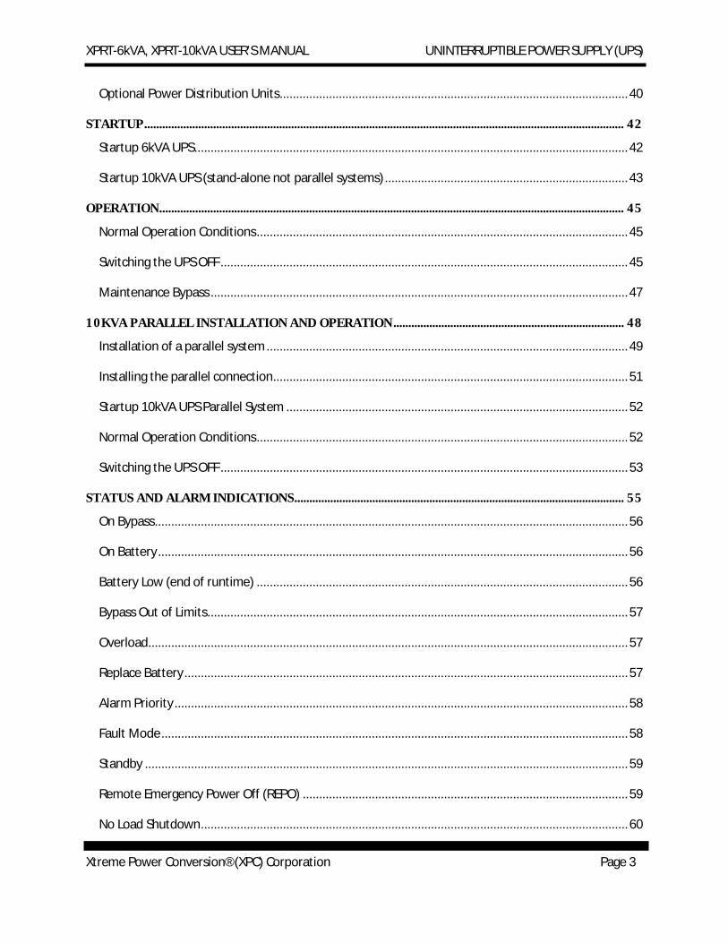
Optional Power Distribution Units .......................................................................................................... 40
STARTUP ................................................................................................................................................................ 42
Startup 6kVA UPS .................................................................................................................................... 42
Startup 10kVA UPS (stand-alone not parallel systems) .......................................................................... 43
OPERATION ........................................................................................................................................................... 45
Normal Operation Conditions ................................................................................................................. 45
Switching the UPS OFF ............................................................................................................................ 45
Maintenance Bypass ............................................................................................................................... 47
10KVA PARALLEL INSTALLATION AND OPERATION ............................................................................. 48
Installation of a parallel system .............................................................................................................. 49
Installing the parallel connection ............................................................................................................ 51
Startup 10kVA UPS Parallel System ........................................................................................................ 52
Normal Operation Conditions ................................................................................................................. 52
Switching the UPS OFF ............................................................................................................................ 53
STATUS AND ALARM INDICATIONS .............................................................................................................. 55
On Bypass ................................................................................................................................................ 56
On Battery ............................................................................................................................................... 56
Battery Low (end of runtime) ................................................................................................................. 56
Bypass Out of Limits ................................................................................................................................ 57
Overload .................................................................................................................................................. 57
Replace Battery ....................................................................................................................................... 57
Alarm Priority .......................................................................................................................................... 58
Fault Mode .............................................................................................................................................. 58
Standby ................................................................................................................................................... 59
Remote Emergency Power Off (REPO) ................................................................................................... 59
No Load Shutdown .................................................................................................................................. 60
XPRT-6kVA, XPRT-10kVA USER’S MANUAL UNINTERRUPTIBLE POWER SUPPLY (UPS)
Xtreme Power Conversion® (XPC) Corporation Page 4
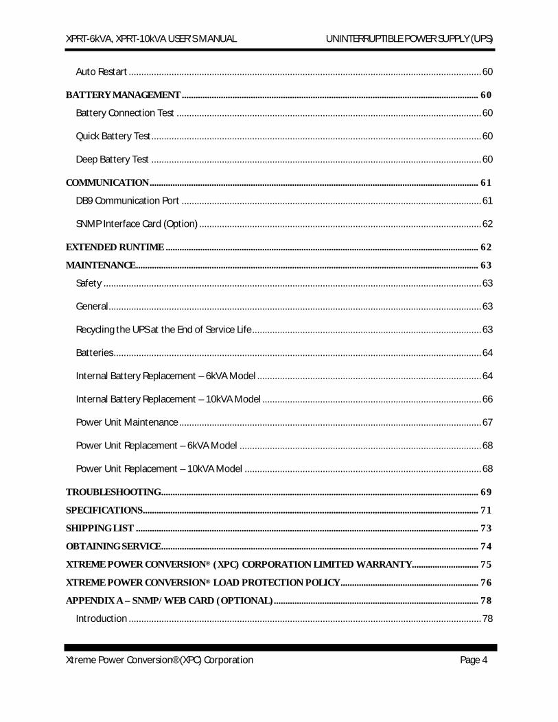
Auto Restart ............................................................................................................................................ 60
BATTERY MANAGEMENT ................................................................................................................................. 60
Battery Connection Test ......................................................................................................................... 60
Quick Battery Test ................................................................................................................................... 60
Deep Battery Test ................................................................................................................................... 60
COMMUNICATION ............................................................................................................................................... 61
DB9 Communication Port ....................................................................................................................... 61
SNMP Interface Card (Option) ................................................................................................................ 62
EXTENDED RUNTIME ........................................................................................................................................ 62
MAINTENANCE ..................................................................................................................................................... 63
Safety ...................................................................................................................................................... 63
General .................................................................................................................................................... 63
Recycling the UPS at the End of Service Life ........................................................................................... 63
Batteries .................................................................................................................................................. 64
Internal Battery Replacement – 6kVA Model ......................................................................................... 64
Internal Battery Replacement – 10kVA Model ....................................................................................... 66
Power Unit Maintenance ........................................................................................................................ 67
Power Unit Replacement – 6kVA Model ................................................................................................ 68
Power Unit Replacement – 10kVA Model .............................................................................................. 68
TROUBLESHOOTING .......................................................................................................................................... 69
SPECIFICATIONS .................................................................................................................................................. 71
SHIPPING LIST ..................................................................................................................................................... 73
OBTAINING SERVICE .......................................................................................................................................... 74
XTREME POWER CONVERSION® (XPC) CORPORATION LIMITED WARRANTY ............................. 75
XTREME POWER CONVERSION® LOAD PROTECTION POLICY ............................................................ 76
APPENDIX A – SNMP/WEB CARD (OPTIONAL) ......................................................................................... 78
Introduction ............................................................................................................................................ 78
XPRT-6kVA, XPRT-10kVA USER’S MANUAL UNINTERRUPTIBLE POWER SUPPLY (UPS)
Xtreme Power Conversion® (XPC) Corporation Page 5
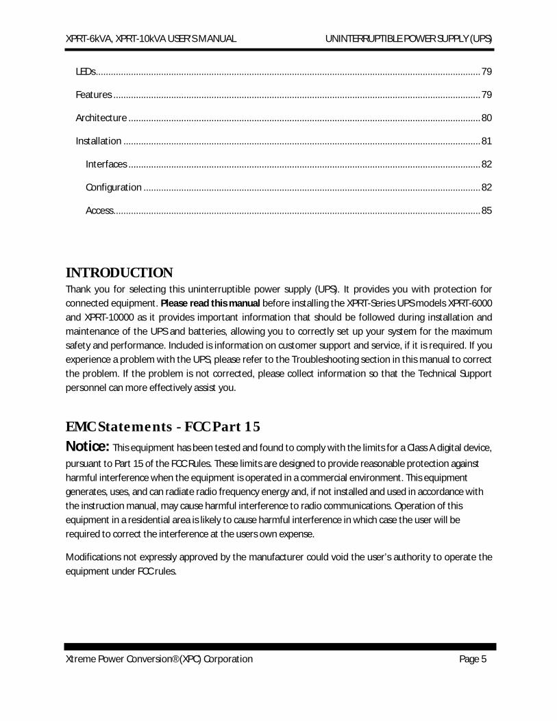
LEDs ......................................................................................................................................................... 79
Features .................................................................................................................................................. 79
Architecture ............................................................................................................................................ 80
Installation .............................................................................................................................................. 81
Interfaces ............................................................................................................................................ 82
Configuration ...................................................................................................................................... 82
Access .................................................................................................................................................. 85
INTRODUCTION Thank you for selecting this uninterruptible power supply (UPS). It provides you with protection for connected equipment. Please read this manual before installing the XPRT-Series UPS models XPRT-6000 and XPRT-10000 as it provides important information that should be followed during installation and maintenance of the UPS and batteries, allowing you to correctly set up your system for the maximum safety and performance. Included is information on customer support and service, if it is required. If you experience a problem with the UPS, please refer to the Troubleshooting section in this manual to correct the problem. If the problem is not corrected, please collect information so that the Technical Support personnel can more effectively assist you.
EMC Statements - FCC Part 15 Notice: This equipment has been tested and found to comply with the limits for a Class A digital device,
pursuant to Part 15 of the FCC Rules. These limits are designed to provide reasonable protection against harmful interference when the equipment is operated in a commercial environment. This equipment generates, uses, and can radiate radio frequency energy and, if not installed and used in accordance with the instruction manual, may cause harmful interference to radio communications. Operation of this equipment in a residential area is likely to cause harmful interference in which case the user will be required to correct the interference at the users own expense.
Modifications not expressly approved by the manufacturer could void the user’s authority to operate the equipment under FCC rules.
XPRT-6kVA, XPRT-10kVA USER’S MANUAL UNINTERRUPTIBLE POWER SUPPLY (UPS)
Xtreme Power Conversion® (XPC) Corporation Page 6
IMPORTANT SAFETY INSTRUCTIONS (SAVE THESE INSTRUCTIONS)
This manual contains important instructions that should be followed during installation and maintenance of the UPS. It also gives all necessary information about the correct use of the UPS. Before attempting to install and start up the UPS, carefully read this manual. Keep this manual next to the unit for future references.
Full understanding of and compliance with the safety instructions and warnings contained in this manual are the
ONLY CONDITIONS
to avoid any dangerous situation during installation, operation and maintenance work, and to preserve the maximum reliability of the UPS system.
Xtreme Power Conversion (XPC) Corp refuses any responsibility in case of non-observance, unauthorized alterations, or improper use of the delivered UPS.
While every care has been taken to ensure the completeness and accuracy of this manual, XPC accepts no responsibility or liability for any loss or damage resulting from the use of the information contained in this document.
This document shall not be copied nor reproduced without the permission of XPC.
Due to technical improvements, some of the information contained in this manual may be changed without notice.
The instructions in this manual are for UPS models XPRT-6000 and XPRT-10000. Check your model number by looking at the top cover of your UPS. Any difference in instructions is clearly indicated in the text (for instance ‘XPRT-10000).
SAFETY WARNINGS AND SYMBOLS Safety Warnings
The text of this manual contains warnings to avoid risk to persons and to avoid damages to the UPS system and the supplied critical loads. Do not proceed beyond these warnings if you do not fully understand and/or are not able to meet the mentioned conditions.
XPRT-6kVA, XPRT-10kVA USER’S MANUAL UNINTERRUPTIBLE POWER SUPPLY (UPS)
Xtreme Power Conversion® (XPC) Corporation Page 7
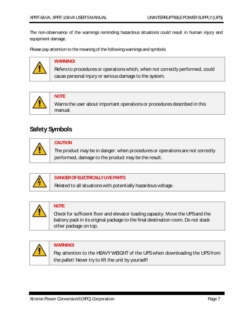
The non-observance of the warnings reminding hazardous situations could result in human injury and equipment damage.
Please pay attention to the meaning of the following warnings and symbols.
WARNING!
Refers to procedures or operations which, when not correctly performed, could cause personal injury or serious damage to the system.
NOTE
Warns the user about important operations or procedures described in this manual.
Safety Symbols
CAUTION
The product may be in danger: when procedures or operations are not correctly performed, damage to the product may be the result.
DANGER OF ELECTRICALLY LIVE PARTS
Related to all situations with potentially hazardous voltage.
NOTE
Check for sufficient floor and elevator loading capacity. Move the UPS and the battery pack in its original package to the final destination room. Do not stack other package on top.
WARNING!
Pay attention to the HEAVY WEIGHT of the UPS when downloading the UPS from the pallet! Never try to lift the unit by yourself!
XPRT-6kVA, XPRT-10kVA USER’S MANUAL UNINTERRUPTIBLE POWER SUPPLY (UPS)
Xtreme Power Conversion® (XPC) Corporation Page 8
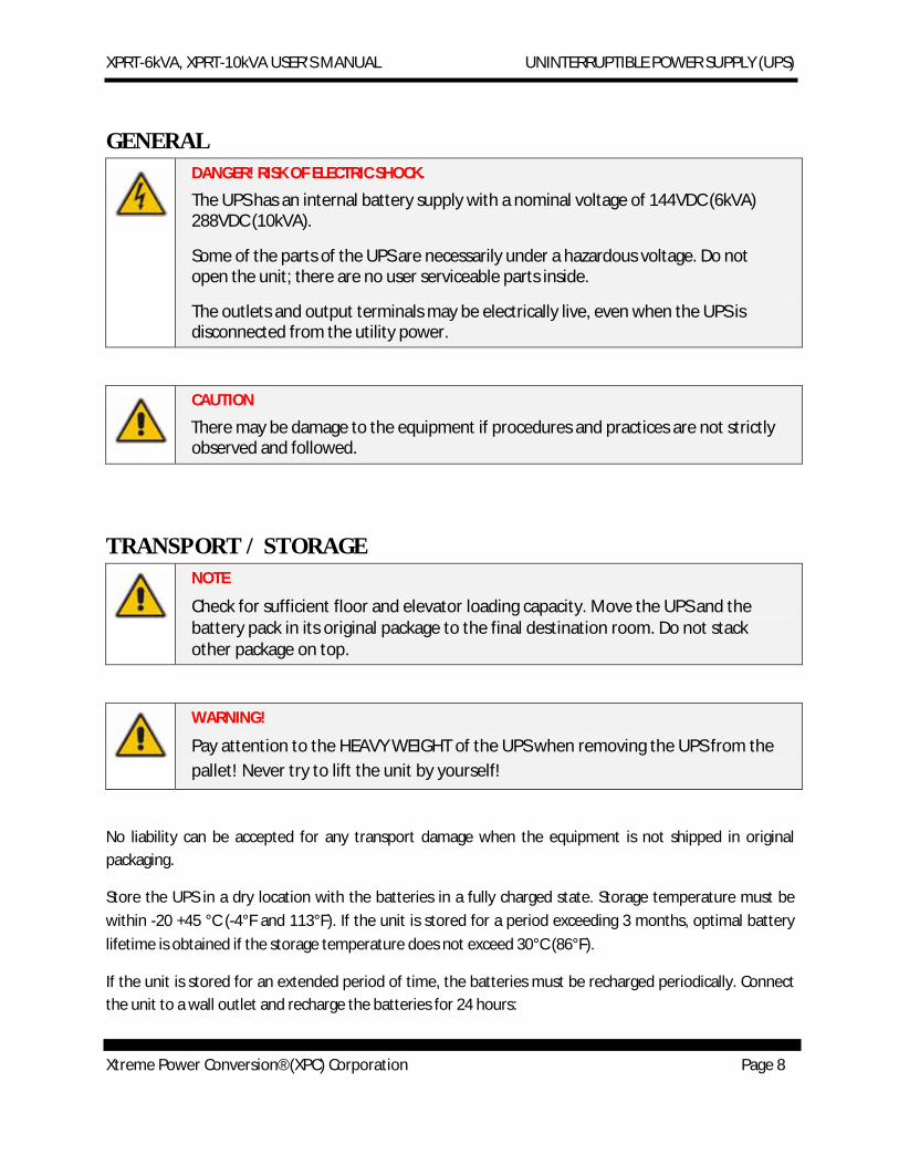
GENERAL DANGER! RISK OF ELECTRIC SHOCK.
The UPS has an internal battery supply with a nominal voltage of 144VDC (6kVA) 288VDC (10kVA).
Some of the parts of the UPS are necessarily under a hazardous voltage. Do not open the unit; there are no user serviceable parts inside.
The outlets and output terminals may be electrically live, even when the UPS is disconnected from the utility power.
CAUTION
There may be damage to the equipment if procedures and practices are not strictly observed and followed.
TRANSPORT / STORAGE NOTE
Check for sufficient floor and elevator loading capacity. Move the UPS and the battery pack in its original package to the final destination room. Do not stack other package on top.
WARNING!
Pay attention to the HEAVY WEIGHT of the UPS when removing the UPS from the pallet! Never try to lift the unit by yourself!
No liability can be accepted for any transport damage when the equipment is not shipped in original packaging.
Store the UPS in a dry location with the batteries in a fully charged state. Storage temperature must be within -20 +45 °C (-4°F and 113°F). If the unit is stored for a period exceeding 3 months, optimal battery lifetime is obtained if the storage temperature does not exceed 30°C (86°F).
If the unit is stored for an extended period of time, the batteries must be recharged periodically. Connect the unit to a wall outlet and recharge the batteries for 24 hours:
XPRT-6kVA, XPRT-10kVA USER’S MANUAL UNINTERRUPTIBLE POWER SUPPLY (UPS)
Xtreme Power Conversion® (XPC) Corporation Page 9
· if the storage temperature is within -20 and +30°C (-4°F and 86°F): every 3 months
· if the storage temperature is within -20 and +45°C (-4°F and 113°F): every 1 month
CAUTION
In case of storage, pay attention to:
MAINTENANCE AND SERVICING · All maintenance and servicing, except replacement of the batteries and plug-in cards, is to be
carried out by qualified skilled personnel only
· A battery can present a risk of electrical shock and high short circuit current
· Never dispose of batteries in a fire: they may explode
· Do not open or mutilate batteries: their contents may be extremely toxic. If exposed to electrolyte, wash immediately with plenty of water
· The batteries must be disconnected during maintenance or service work
· When replacing the batteries, use only the same type and size battery
· The following precautions should be observed when working on batteries:
o Remove watches, rings or other metal objects
o Use tools with insulated handles
o Wear rubber gloves and boots
o Do not lay tools or metal parts on top of batteries
o Disconnect charging source prior to connecting or disconnect battery terminals
o Determine if the battery is inadvertently grounded. If inadvertently grounded, remove source of ground. Contact with any part of a grounded battery can result in electrical shock. The likelihood of such shock will be reduced if such grounds are removed during installation and maintenance.
· Avoid charging in a sealed container
XPRT-6kVA, XPRT-10kVA USER’S MANUAL UNINTERRUPTIBLE POWER SUPPLY (UPS)
Xtreme Power Conversion® (XPC) Corporation Page 10
NOTE
Do not attempt to service the UPS unless you have had proper training. Refer all maintenance and servicing, except replacement of the batteries, power unit (10kVA), and plug-in cards, to properly qualified, skilled, and competent service personnel.
Qualified, skilled personnel are persons who (because of their training, experience, and position as well as their knowledge of appropriate standards, regulations, health and safety requirements and working conditions) are authorized to be responsible for the safety of the equipment, at all times whilst carrying out their normal duties and are therefore aware of, and can report, possible hazards (observe IEC 60364 and national wiring regulations and accident prevention rules).
INTRODUCTION The information provided in this manual covers single phase 6000 and 10000 VA uninterruptible power systems, their basic functions, operating procedures, options available, and emergency situations. It also includes information on how to ship, store, handle, and install the equipment. Only detailed requirements of the UPS units are described herein, and installation must be carried out in accordance with this manual. Electrical installation must also carefully follow local legislation and regulations. Only qualified personnel should conduct these installations as failure to acknowledge electrical hazards could prove to be fatal.
PRODUCT DESCRIPTION Many different kinds of sensitive electrical equipment can be protected by an Uninterruptible Power Supply (UPS) including computers, workstations, process control systems, telecommunications systems, sales terminals, other critical instrumentation, etc. The purpose of the UPS is to protect these systems from poor quality utility power, complete loss of power, or other associated problems.
Electrical interference exists in many forms, causing problems in AC power, from lightning, power company accidents and radio transmission motors, air conditioners, and vending machines. Protection of sensitive electrical equipment is vital to protect against power outages, low or high voltage conditions, slow voltage fluctuations, frequency variations, differential and common-mode noise, transients, etc.
To prevent power line problems from reaching critical systems causing damage to software, hardware, and equipment malfunctions, the UPS maintains constant voltage, isolating critical load output and cleaning the utility AC power.
XPRT-6kVA, XPRT-10kVA USER’S MANUAL UNINTERRUPTIBLE POWER SUPPLY (UPS)
Xtreme Power Conversion® (XPC) Corporation Page 11
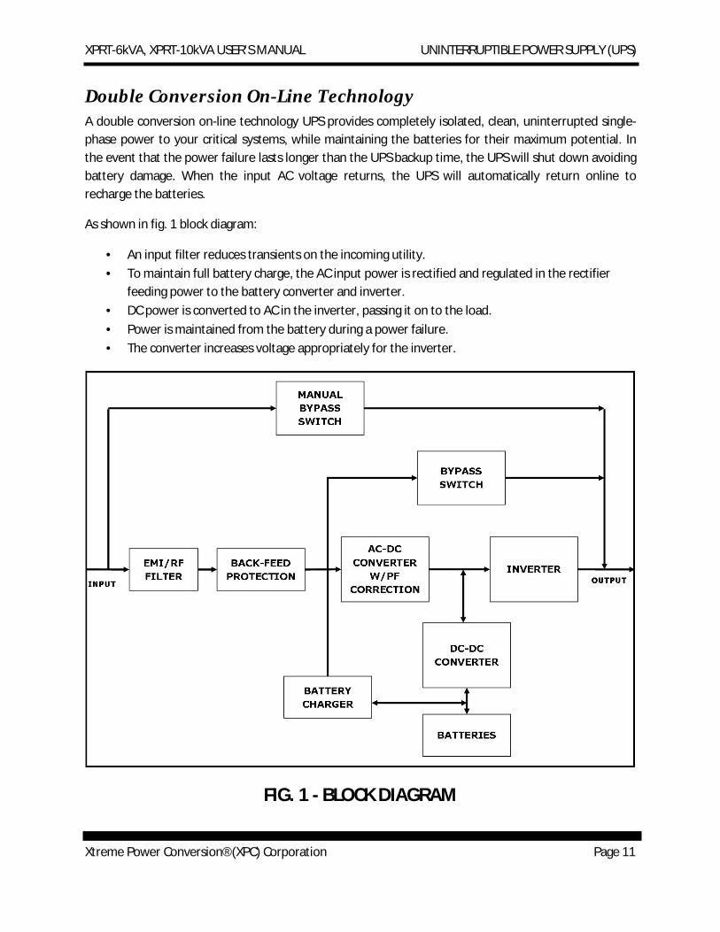
Double Conversion On-Line Technology A double conversion on-line technology UPS provides completely isolated, clean, uninterrupted single-phase power to your critical systems, while maintaining the batteries for their maximum potential. In the event that the power failure lasts longer than the UPS backup time, the UPS will shut down avoiding battery damage. When the input AC voltage returns, the UPS will automatically return online to recharge the batteries.
As shown in fig. 1 block diagram:
· An input filter reduces transients on the incoming utility. · To maintain full battery charge, the AC input power is rectified and regulated in the rectifier
feeding power to the battery converter and inverter. · DC power is converted to AC in the inverter, passing it on to the load. · Power is maintained from the battery during a power failure. · The converter increases voltage appropriately for the inverter.
FIG. 1 - BLOCK DIAGRAM
XPRT-6kVA, XPRT-10kVA USER’S MANUAL UNINTERRUPTIBLE POWER SUPPLY (UPS)
Xtreme Power Conversion® (XPC) Corporation Page 12
Efficiency Optimizer Function The Efficiency Optimizer Function is a new feature for the UPS, adding cost effectiveness, minimizing power loss and reducing power consumption. Alternating between bypass and on-line modes is achieved automatically and in accordance with the conditions of the utility power. On-line mode may be used during times of intermittent power, and bypass mode used when power flows smoothly, in order to obtain greatest efficiency. Irregularities can be detected in less than a second, and on-line mode reactivates immediately. Switching back to on-line mode occurs when input voltage is outside ±10% of nominal (±15% selectable), when input frequency is outside of ±3Hz or when no input line is available.
Although high efficiency is standard, the default operation is in on-line mode. Bypass can be activated in the LCD panel; though on-line can be run permanently if preferred.
Free Run Mode The UPS operates in Free Run Mode when input frequency is outside of the selected input frequency range. Free Run Mode is when output frequency does not match input frequency. When starting the UPS, the frequency regulation detected is 50 or 60 Hz ±0.25Hz.
Diagnostic Tests When the UPS is started, a diagnostic test is automatically executed, checking the electronics and batteries, reporting any problems on the LED display.
An Xtreme Battery Management system always monitors the conditions of the batteries, sending any forewarnings if replacement of batteries is required. Every 30 days of normal mode operation, a battery discharge test is automatically performed, reporting any problems on the LED display.
Except during the first 24 hours after startup while the UPS is in charging mode, diagnostic tests can be performed manually from the front panel at any time.
System Configuration The UPS device and the internal batteries make up the system. Depending on the site and load requirements of the installation, certain additional options are available for the solution.
Planning a UPS system, the following should be taken into consideration:
· The total demand of the protected system shall dictate the output power rating (VA). Allow a margin for future expansion or calculation inaccuracies from measured power requirements.
· Backup time required will indicate the battery size needed. If the load is less than the UPS nominal power rating, then actual backup time is longer.
· The following options are available: o Extended Battery Packs (maximum of 3 battery packs of same model)
XPRT-6kVA, XPRT-10kVA USER’S MANUAL UNINTERRUPTIBLE POWER SUPPLY (UPS)
Xtreme Power Conversion® (XPC) Corporation Page 13
§ XPRT-BP4-90000019 for 6000 § XPRT-BP5-90000030 for 10000
o Connectivity Options –SNMP/WEB card § XPRT-SNMP2-90000031
o 4-Post Mounting Rail Kit § XPRT-RR2-90000032
o 10kVA Power Distribution Unit e/w (8)5-20R+(2)L5-20R+(2)L6-30R § XPRT-PDU3-90000035
o Power Distribution Units for additional receptacles § XPD1420HV-90000045 provides 12FT 5-20P INPUT + (14)5-20R § XPD1420HVA-90000050 provides 12FT 5-20P INPUT + (14)5-20R + AMP METER
See the Specification section of this manual for addition model information.
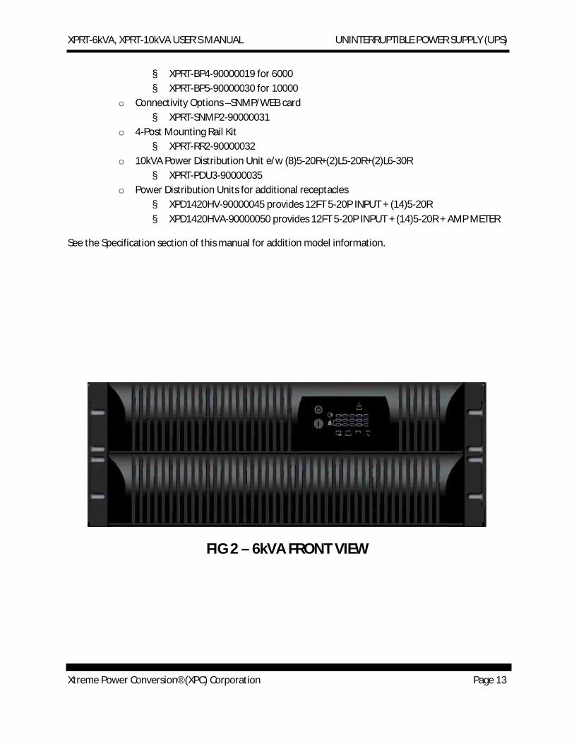
FIG 2 – 6kVA FRONT VIEW
XPRT-6kVA, XPRT-10kVA USER’S MANUAL UNINTERRUPTIBLE POWER SUPPLY (UPS)
Xtreme Power Conversion® (XPC) Corporation Page 14
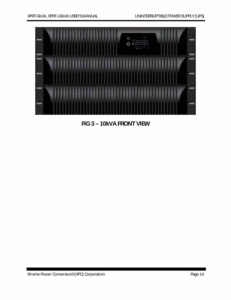
FIG 3 – 10kVA FRONT VIEW
XPRT-6kVA, XPRT-10kVA USER’S MANUAL UNINTERRUPTIBLE POWER SUPPLY (UPS)
Xtreme Power Conversion® (XPC) Corporation Page 15
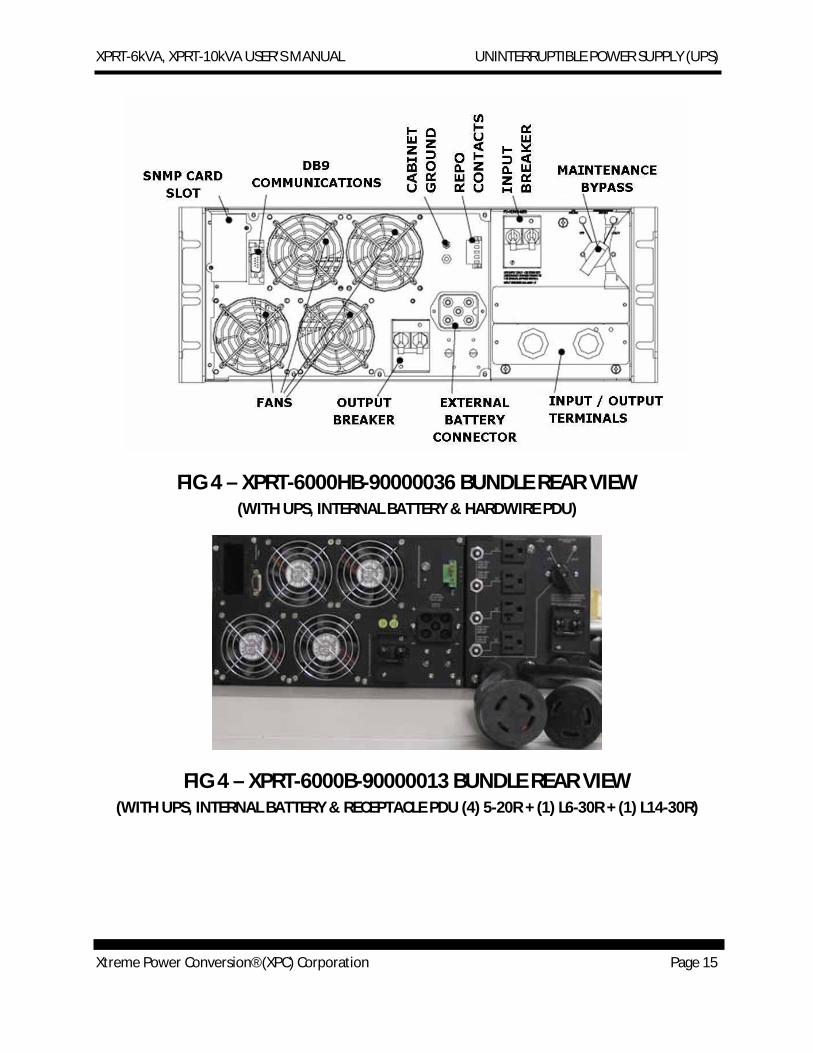
FIG 4 – XPRT-6000HB-90000036 BUNDLE REAR VIEW (WITH UPS, INTERNAL BATTERY & HARDWIRE PDU)
FIG 4 – XPRT-6000B-90000013 BUNDLE REAR VIEW (WITH UPS, INTERNAL BATTERY & RECEPTACLE PDU (4) 5-20R + (1) L6-30R + (1) L14-30R)
XPRT-6kVA, XPRT-10kVA USER’S MANUAL UNINTERRUPTIBLE POWER SUPPLY (UPS)
Xtreme Power Conversion® (XPC) Corporation Page 16
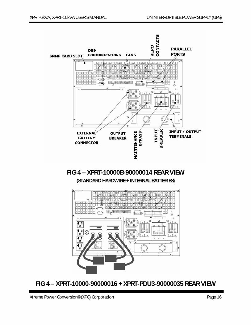
FIG 4 – XPRT-10000B-90000014 REAR VIEW (STANDARD HARDWIRE + INTERNAL BATTERIES)
FIG 4 – XPRT-10000-90000016 + XPRT-PDU3-90000035 REAR VIEW
XPRT-6kVA, XPRT-10kVA USER’S MANUAL UNINTERRUPTIBLE POWER SUPPLY (UPS)
Xtreme Power Conversion® (XPC) Corporation Page 17
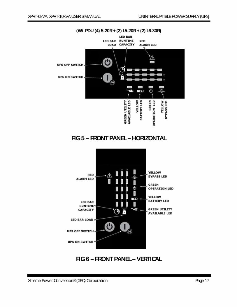
(W/ PDU (4) 5-20R + (2) L5-20R + (2) L6-30R)
FIG 5 – FRONT PANEL – HORIZONTAL
FIG 6 – FRONT PANEL – VERTICAL
XPRT-6kVA, XPRT-10kVA USER’S MANUAL UNINTERRUPTIBLE POWER SUPPLY (UPS)
Xtreme Power Conversion® (XPC) Corporation Page 18
UPS Off Switch
Switches the UPS from normal operation to bypass and from bypass or battery to standby
UPS On Switch
Switches on the UPS, starts quick battery test, mute the buzzer
Green Utility Available LED
Indicates availability of utility input power
Yellow Battery LED
This LED will be in during on-battery operation: the utility input power fails, and the internal batteries (and external battery packs if available) supply the power until either the batteries are depleted or the utility input power returns
Green Operation LED
This LED will be on when the output is supplied by the UPS (not on bypass)
Yellow Bypass LED
This LED will be on when the UPS operates in Bypass Mode: the utility input power is passing directly to the load. If this LED blinks, then the input voltage is out of bypass tolerance
Red Alarm LED
This LED is on in case of an alarm
LED Bar Runtime Capacity (Green)
These LEDs indicate the remaining available battery runtime for the actual load in % of the maximum runtime. When the Alarm LED is on, this bar may show a combination of LEDs, describing the Alarm cause.
1 LED = 0-20% 2 LEDs = 21-40% 3 LEDs = 41-60%
XPRT-6kVA, XPRT-10kVA USER’S MANUAL UNINTERRUPTIBLE POWER SUPPLY (UPS)
Xtreme Power Conversion® (XPC) Corporation Page 19
4 LEDs = 61-80% 5 LEDs = 81-100%
LED Bar Load (Green or Yellow)
These LEDs indicate to what extent the output capacity of the UPS is used by the actual load for each output line (L1 and L2). If for example, the 25%, 50%, and 75% LEDs are on for Line 1, and the 25% and 50% LEDs are on for Line 2, the load exceeds 50% of the maximum load for Line 1 and 25% of the maximum load for Line 2. If all 5 LEDs are on, the unit operates in overload. As this is an abnormal situation, the alarm LED will also be on.
1 LED = 0-25% Green 2 LEDs = 26-50% Green 3 LEDs = 51-75% Green 4 LEDs = 76-100% Green 5 LEDs = >100% Yellow
Remote Emergency Power Off (EPO) Port
A customer supplied switch located remotely can be used to open the EPO connection and allows the UPS output receptacles to be switched off. Since the EPO shuts down the equipment immediately, orderly shutdown procedures are not followed by any power management software. The UPS will have to be manually restarted in order to regain power to the outlets on the UPS.
HARDWARE INSTALLATION GUIDE Inspect the UPS for damage after unpacking. If any damage is present please immediately notify the carrier and place of purchase.
NOTE
The internal battery packs for these UPS ship separately. FOR the 6kVA model there is 1 internal battery pack, and for the 10kVA model there are 2 internal battery packs are shipped separately.
WARNING! In case of recognizable damage:
DO NOT connect any voltage to the unit
DO NOT put the unit into operation
XPRT-6kVA, XPRT-10kVA USER’S MANUAL UNINTERRUPTIBLE POWER SUPPLY (UPS)
Xtreme Power Conversion® (XPC) Corporation Page 20
Safety Information Information presented here is vital to all personnel. Please read all Safety information.
IMPORTANT
Before making any connection and switching on the XPRT Series UPS, please check the following conditions:
· All electrical connections are to be realized by qualified skilled personnel only.
· To avoid potential health risks, electrical components should not be mechanically damaged or destroyed. Do not touch electronic components. They may be electrostatic sensitive and are for that reason easily damaged due to improper handling.
· Avoid locations that are excessively humid, near water, near heat sources or in direct sunlight. It is important that the unit has adequate ventilation. Maintain air movement around and through the unit. Do not block the air vents.
· The ambient temperature should not exceed 40°C(104°F). Optimal battery lifetime is obtained if the ambient temperature does not exceed 30°C (86°F).
· Avoid spilling liquids or dropping any foreign object into the UPS.
· The UPS should only be powered from a two phase, four wire AC source equipped with neutral and earth connection. The input utility is 100 - 127 Volts (Line-N) and 60 Hz (if the input utility frequency is 50Hz, the output frequency of the UPS can be changed).
· The total power demand of the connected equipment does not exceed the rated output power of the XPRT Series UPS
· The branch circuit supply has to be protected as follows:
UPS model Branch protection
XPRT-6000 30A slow
XPRT-10000 60A slow
CAUTION
To reduce risk of fire, connect the UPS only to a circuit provided with fuse or circuit breaker values as shown above.
XPRT-6kVA, XPRT-10kVA USER’S MANUAL UNINTERRUPTIBLE POWER SUPPLY (UPS)
Xtreme Power Conversion® (XPC) Corporation Page 21
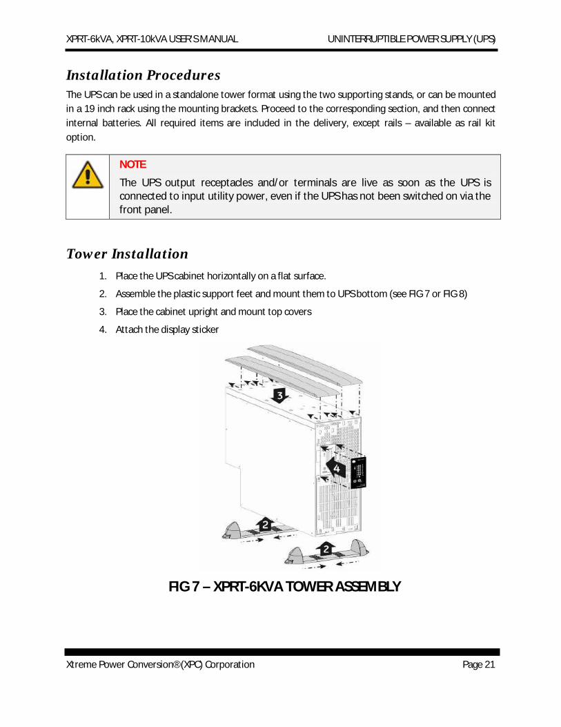
Installation Procedures The UPS can be used in a standalone tower format using the two supporting stands, or can be mounted in a 19 inch rack using the mounting brackets. Proceed to the corresponding section, and then connect internal batteries. All required items are included in the delivery, except rails – available as rail kit option.
NOTE
The UPS output receptacles and/or terminals are live as soon as the UPS is connected to input utility power, even if the UPS has not been switched on via the front panel.
Tower Installation 1. Place the UPS cabinet horizontally on a flat surface.
2. Assemble the plastic support feet and mount them to UPS bottom (see FIG 7 or FIG 8)
3. Place the cabinet upright and mount top covers
4. Attach the display sticker
FIG 7 – XPRT-6KVA TOWER ASSEMBLY
XPRT-6kVA, XPRT-10kVA USER’S MANUAL UNINTERRUPTIBLE POWER SUPPLY (UPS)
Xtreme Power Conversion® (XPC) Corporation Page 22
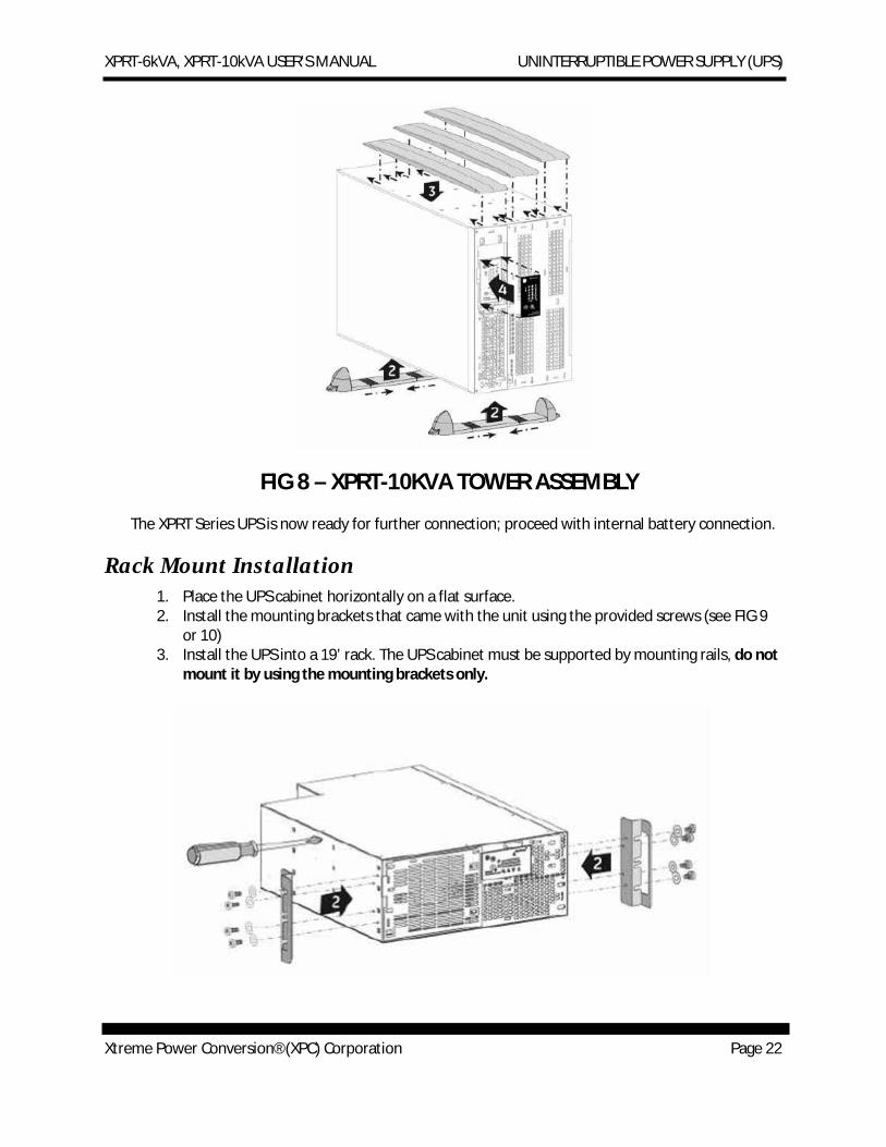
FIG 8 – XPRT-10KVA TOWER ASSEMBLY
The XPRT Series UPS is now ready for further connection; proceed with internal battery connection.
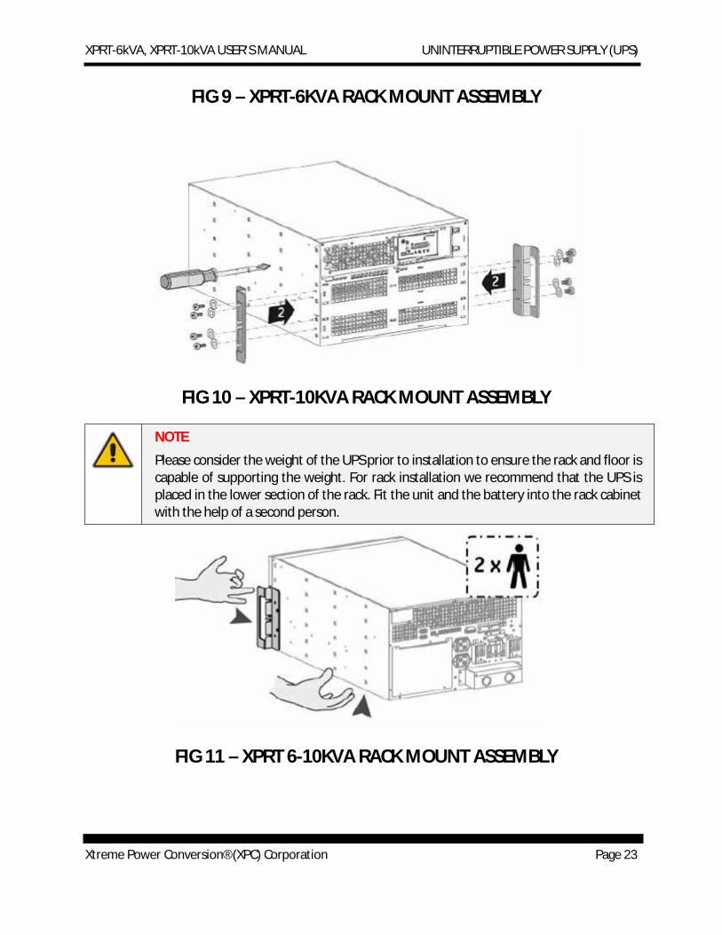
Rack Mount Installation 1. Place the UPS cabinet horizontally on a flat surface. 2. Install the mounting brackets that came with the unit using the provided screws (see FIG 9
or 10) 3. Install the UPS into a 19’ rack. The UPS cabinet must be supported by mounting rails, do not
mount it by using the mounting brackets only.
XPRT-6kVA, XPRT-10kVA USER’S MANUAL UNINTERRUPTIBLE POWER SUPPLY (UPS)
Xtreme Power Conversion® (XPC) Corporation Page 23
FIG 9 – XPRT-6KVA RACK MOUNT ASSEMBLY
FIG 10 – XPRT-10KVA RACK MOUNT ASSEMBLY
NOTE
Please consider the weight of the UPS prior to installation to ensure the rack and floor is capable of supporting the weight. For rack installation we recommend that the UPS is placed in the lower section of the rack. Fit the unit and the battery into the rack cabinet with the help of a second person.
FIG 11 – XPRT 6-10KVA RACK MOUNT ASSEMBLY
XPRT-6kVA, XPRT-10kVA USER’S MANUAL UNINTERRUPTIBLE POWER SUPPLY (UPS)
Xtreme Power Conversion® (XPC) Corporation Page 24
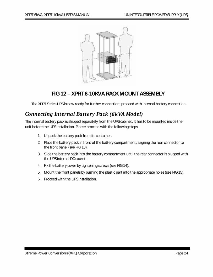
FIG 12 – XPRT 6-10KVA RACK MOUNT ASSEMBLY
The XPRT Series UPS is now ready for further connection; proceed with internal battery connection.
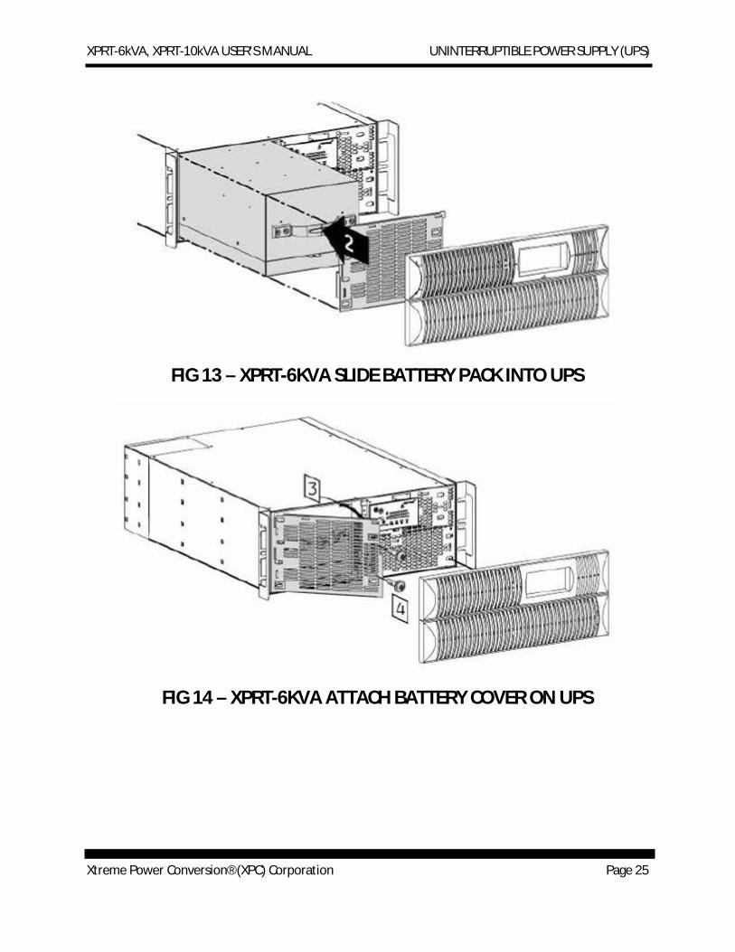
Connecting Internal Battery Pack (6kVA Model) The internal battery pack is shipped separately from the UPS cabinet. It has to be mounted inside the unit before the UPS installation. Please proceed with the following steps:
1. Unpack the battery pack from its container.
2. Place the battery pack in front of the battery compartment, aligning the rear connector to the front panel (see FIG 13).
3. Slide the battery pack into the battery compartment until the rear connector is plugged with the UPS internal DC socket.
4. Fix the battery cover by tightening screws (see FIG 14).
5. Mount the front panels by pushing the plastic part into the appropriate holes (see FIG 15).
6. Proceed with the UPS installation.
XPRT-6kVA, XPRT-10kVA USER’S MANUAL UNINTERRUPTIBLE POWER SUPPLY (UPS)
Xtreme Power Conversion® (XPC) Corporation Page 25
FIG 13 – XPRT-6KVA SLIDE BATTERY PACK INTO UPS
FIG 14 – XPRT-6KVA ATTACH BATTERY COVER ON UPS
XPRT-6kVA, XPRT-10kVA USER’S MANUAL UNINTERRUPTIBLE POWER SUPPLY (UPS)
Xtreme Power Conversion® (XPC) Corporation Page 26
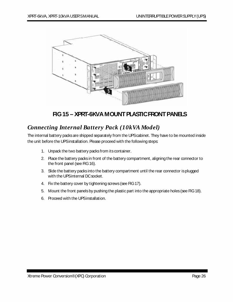
FIG 15 – XPRT-6KVA MOUNT PLASTIC FRONT PANELS
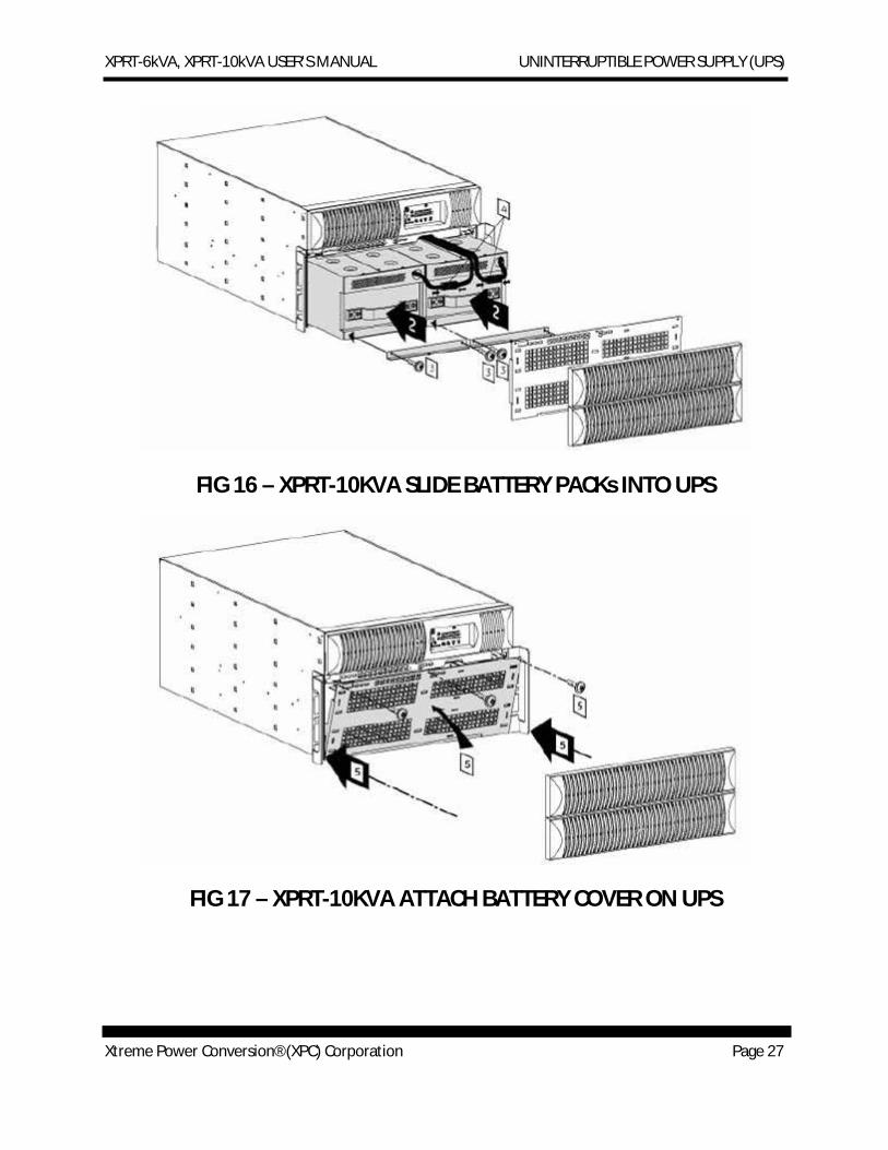
Connecting Internal Battery Pack (10kVA Model) The internal battery packs are shipped separately from the UPS cabinet. They have to be mounted inside the unit before the UPS installation. Please proceed with the following steps:
1. Unpack the two battery packs from its container.
2. Place the battery packs in front of the battery compartment, aligning the rear connector to the front panel (see FIG 16).
3. Slide the battery packs into the battery compartment until the rear connector is plugged with the UPS internal DC socket.
4. Fix the battery cover by tightening screws (see FIG 17).
5. Mount the front panels by pushing the plastic part into the appropriate holes (see FIG 18).
6. Proceed with the UPS installation.
XPRT-6kVA, XPRT-10kVA USER’S MANUAL UNINTERRUPTIBLE POWER SUPPLY (UPS)
Xtreme Power Conversion® (XPC) Corporation Page 27
FIG 16 – XPRT-10KVA SLIDE BATTERY PACKs INTO UPS
FIG 17 – XPRT-10KVA ATTACH BATTERY COVER ON UPS
XPRT-6kVA, XPRT-10kVA USER’S MANUAL UNINTERRUPTIBLE POWER SUPPLY (UPS)
Xtreme Power Conversion® (XPC) Corporation Page 28
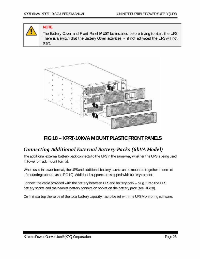
NOTE
The Battery Cover and Front Panel MUST be installed before trying to start the UPS. There is a switch that the Battery Cover activates - if not activated the UPS will not start.
FIG 18 – XPRT-10KVA MOUNT PLASTIC FRONT PANELS
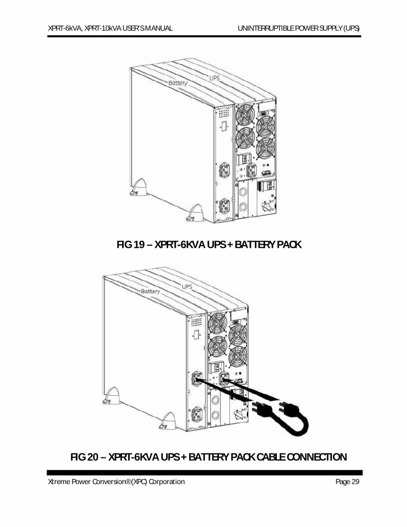
Connecting Additional External Battery Packs (6kVA Model) The additional external battery pack connects to the UPS in the same way whether the UPS is being used in tower or rack mount format.
When used in tower format, the UPS and additional battery packs can be mounted together in one set of mounting supports (see FIG 19). Additional supports are shipped with battery cabinet.
Connect the cable provided with the battery between UPS and battery pack – plug it into the UPS battery socket and the nearest battery connection socket on the battery pack (see FIG 20).
On first startup the value of the total battery capacity has to be set with the UPS Monitoring software.
XPRT-6kVA, XPRT-10kVA USER’S MANUAL UNINTERRUPTIBLE POWER SUPPLY (UPS)
Xtreme Power Conversion® (XPC) Corporation Page 29
FIG 19 – XPRT-6KVA UPS + BATTERY PACK
FIG 20 – XPRT-6KVA UPS + BATTERY PACK CABLE CONNECTION
XPRT-6kVA, XPRT-10kVA USER’S MANUAL UNINTERRUPTIBLE POWER SUPPLY (UPS)
Xtreme Power Conversion® (XPC) Corporation Page 30
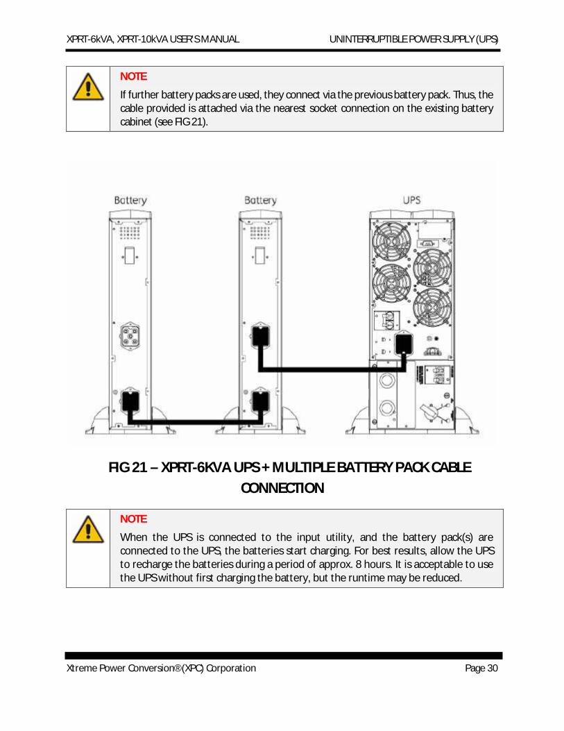
NOTE
If further battery packs are used, they connect via the previous battery pack. Thus, the cable provided is attached via the nearest socket connection on the existing battery cabinet (see FIG 21).
FIG 21 – XPRT-6KVA UPS + MULTIPLE BATTERY PACK CABLE CONNECTION
NOTE
When the UPS is connected to the input utility, and the battery pack(s) are connected to the UPS, the batteries start charging. For best results, allow the UPS to recharge the batteries during a period of approx. 8 hours. It is acceptable to use the UPS without first charging the battery, but the runtime may be reduced.
XPRT-6kVA, XPRT-10kVA USER’S MANUAL UNINTERRUPTIBLE POWER SUPPLY (UPS)
Xtreme Power Conversion® (XPC) Corporation Page 31
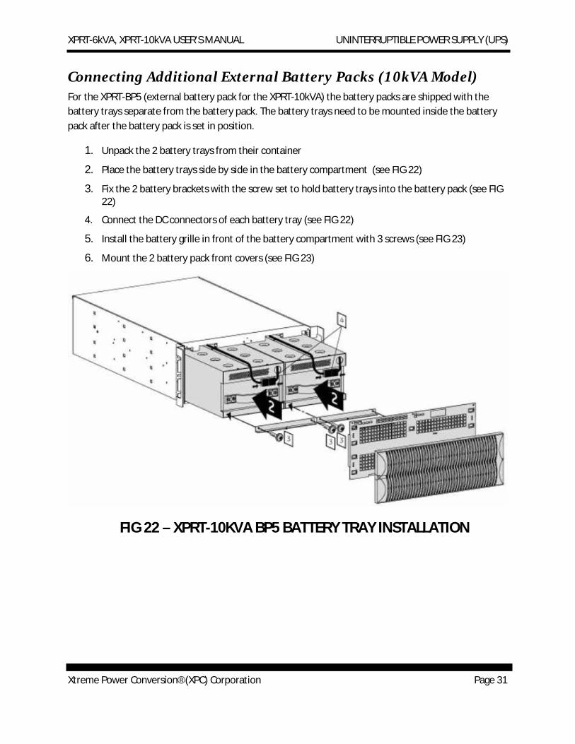
Connecting Additional External Battery Packs (10kVA Model) For the XPRT-BP5 (external battery pack for the XPRT-10kVA) the battery packs are shipped with the battery trays separate from the battery pack. The battery trays need to be mounted inside the battery pack after the battery pack is set in position.
1. Unpack the 2 battery trays from their container
2. Place the battery trays side by side in the battery compartment (see FIG 22)
3. Fix the 2 battery brackets with the screw set to hold battery trays into the battery pack (see FIG 22)
4. Connect the DC connectors of each battery tray (see FIG 22)
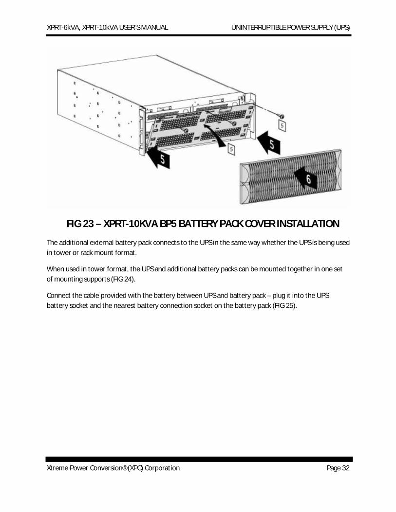
5. Install the battery grille in front of the battery compartment with 3 screws (see FIG 23)
6. Mount the 2 battery pack front covers (see FIG 23)
FIG 22 – XPRT-10KVA BP5 BATTERY TRAY INSTALLATION
XPRT-6kVA, XPRT-10kVA USER’S MANUAL UNINTERRUPTIBLE POWER SUPPLY (UPS)
Xtreme Power Conversion® (XPC) Corporation Page 32
FIG 23 – XPRT-10KVA BP5 BATTERY PACK COVER INSTALLATION
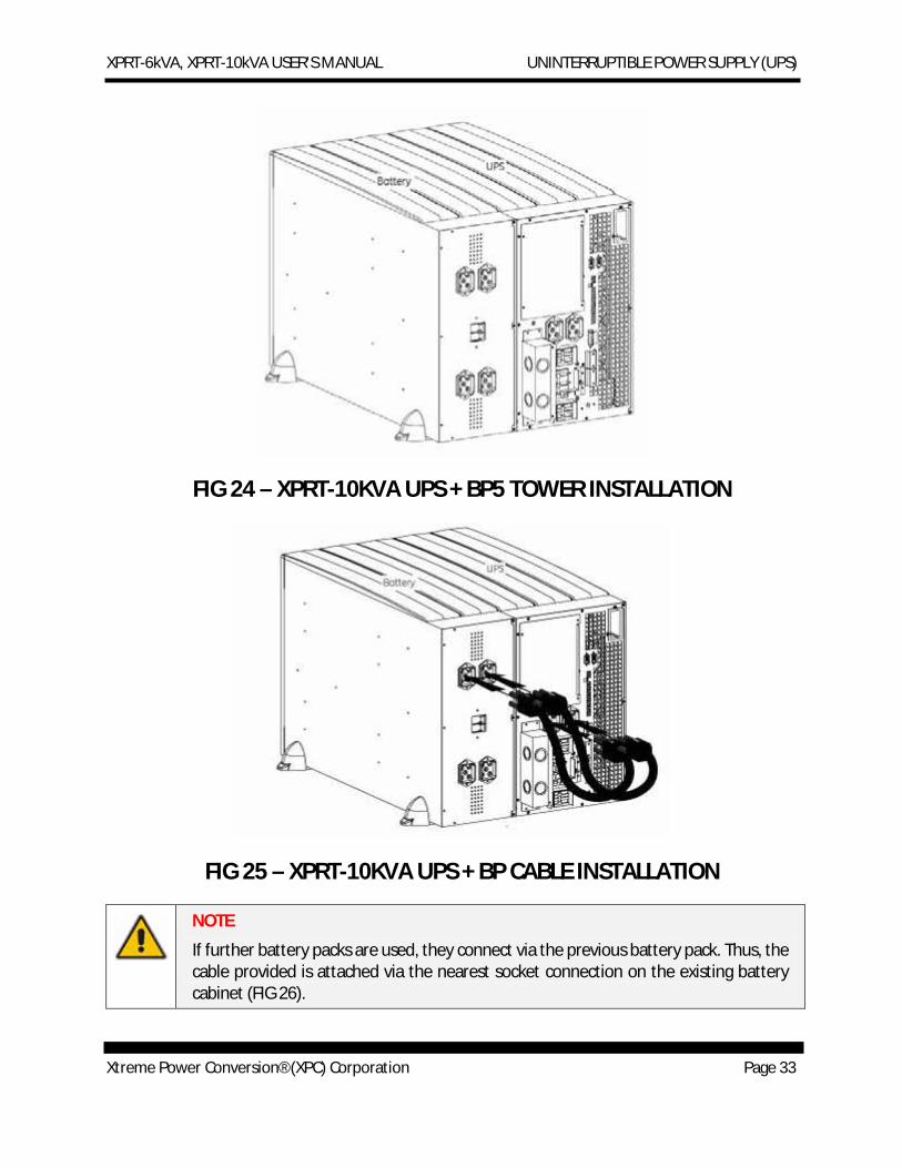
The additional external battery pack connects to the UPS in the same way whether the UPS is being used in tower or rack mount format.
When used in tower format, the UPS and additional battery packs can be mounted together in one set of mounting supports (FIG 24).
Connect the cable provided with the battery between UPS and battery pack – plug it into the UPS battery socket and the nearest battery connection socket on the battery pack (FIG 25).
XPRT-6kVA, XPRT-10kVA USER’S MANUAL UNINTERRUPTIBLE POWER SUPPLY (UPS)
Xtreme Power Conversion® (XPC) Corporation Page 33
FIG 24 – XPRT-10KVA UPS + BP5 TOWER INSTALLATION
FIG 25 – XPRT-10KVA UPS + BP CABLE INSTALLATION
NOTE
If further battery packs are used, they connect via the previous battery pack. Thus, the cable provided is attached via the nearest socket connection on the existing battery cabinet (FIG 26).
XPRT-6kVA, XPRT-10kVA USER’S MANUAL UNINTERRUPTIBLE POWER SUPPLY (UPS)
Xtreme Power Conversion® (XPC) Corporation Page 34
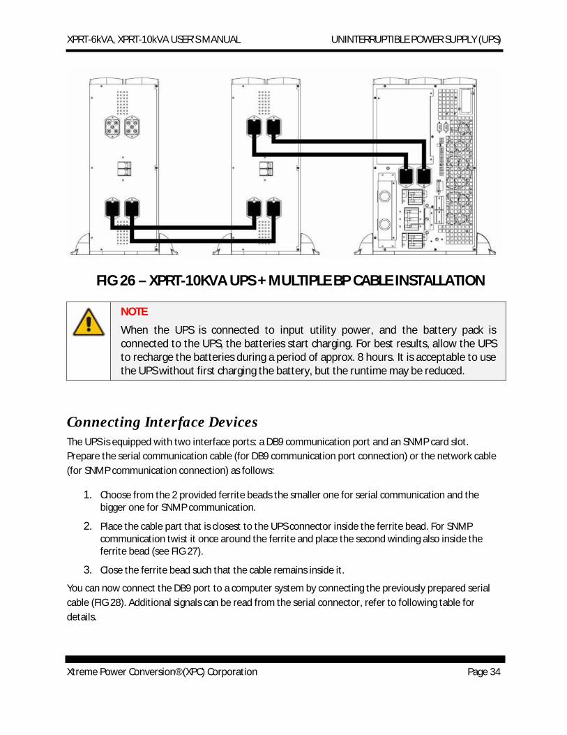
FIG 26 – XPRT-10KVA UPS + MULTIPLE BP CABLE INSTALLATION
NOTE
When the UPS is connected to input utility power, and the battery pack is connected to the UPS, the batteries start charging. For best results, allow the UPS to recharge the batteries during a period of approx. 8 hours. It is acceptable to use the UPS without first charging the battery, but the runtime may be reduced.
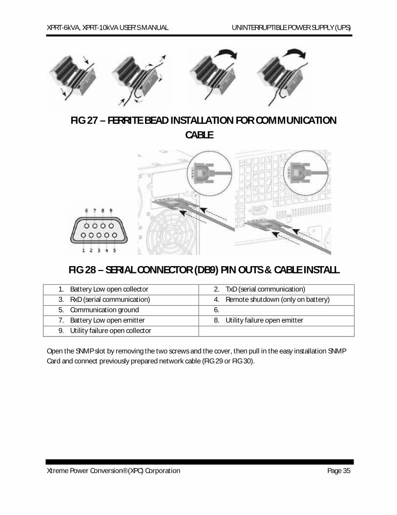
Connecting Interface Devices The UPS is equipped with two interface ports: a DB9 communication port and an SNMP card slot. Prepare the serial communication cable (for DB9 communication port connection) or the network cable (for SNMP communication connection) as follows:
1. Choose from the 2 provided ferrite beads the smaller one for serial communication and the bigger one for SNMP communication.
2. Place the cable part that is closest to the UPS connector inside the ferrite bead. For SNMP communication twist it once around the ferrite and place the second winding also inside the ferrite bead (see FIG 27).
3. Close the ferrite bead such that the cable remains inside it.
You can now connect the DB9 port to a computer system by connecting the previously prepared serial cable (FIG 28). Additional signals can be read from the serial connector, refer to following table for details.
XPRT-6kVA, XPRT-10kVA USER’S MANUAL UNINTERRUPTIBLE POWER SUPPLY (UPS)
Xtreme Power Conversion® (XPC) Corporation Page 35
FIG 27 – FERRITE BEAD INSTALLATION FOR COMMUNICATION CABLE
FIG 28 – SERIAL CONNECTOR (DB9) PIN OUTS & CABLE INSTALL
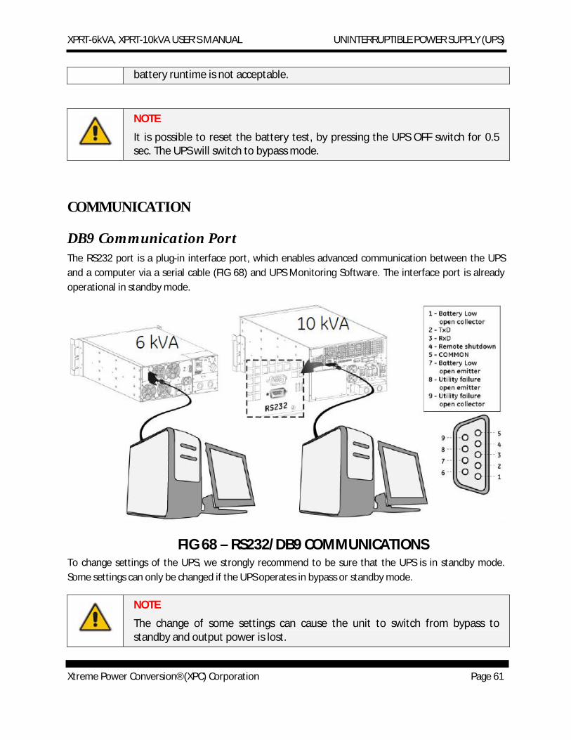
1. Battery Low open collector 2. TxD (serial communication) 3. RxD (serial communication) 4. Remote shutdown (only on battery) 5. Communication ground 6. 7. Battery Low open emitter 8. Utility failure open emitter 9. Utility failure open collector
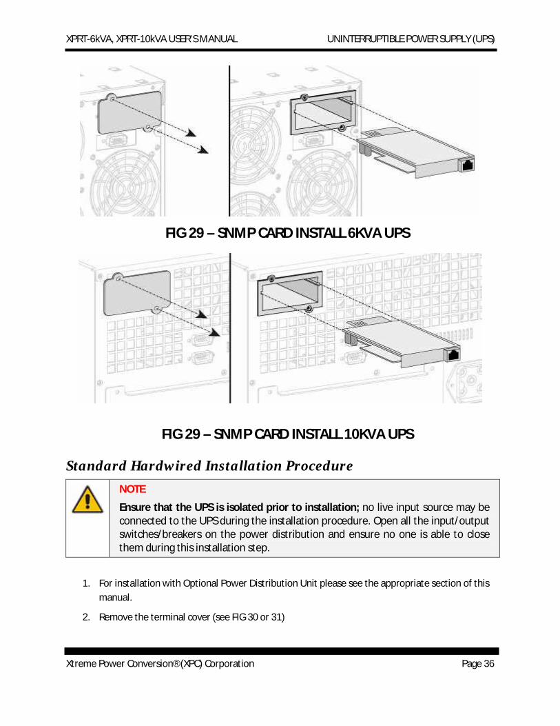
Open the SNMP slot by removing the two screws and the cover, then pull in the easy installation SNMP Card and connect previously prepared network cable (FIG 29 or FIG 30).
XPRT-6kVA, XPRT-10kVA USER’S MANUAL UNINTERRUPTIBLE POWER SUPPLY (UPS)
Xtreme Power Conversion® (XPC) Corporation Page 36
FIG 29 – SNMP CARD INSTALL 6KVA UPS
FIG 29 – SNMP CARD INSTALL 10KVA UPS
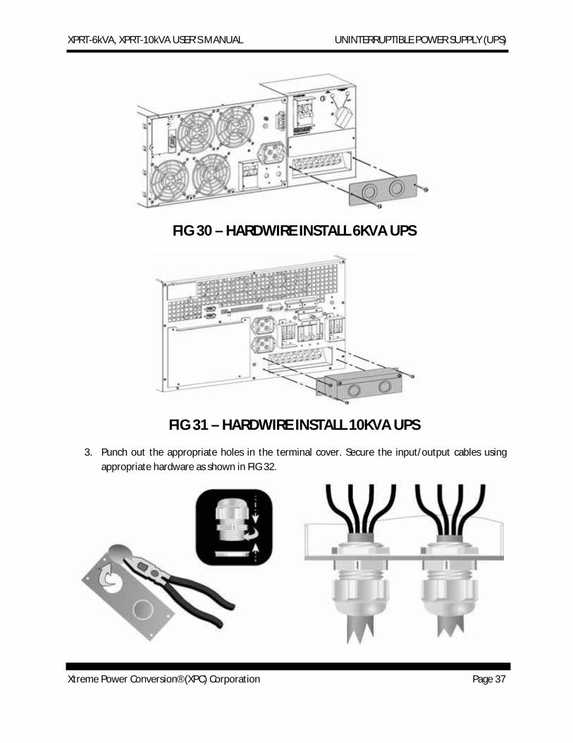
Standard Hardwired Installation Procedure NOTE
Ensure that the UPS is isolated prior to installation; no live input source may be connected to the UPS during the installation procedure. Open all the input/output switches/breakers on the power distribution and ensure no one is able to close them during this installation step.
1. For installation with Optional Power Distribution Unit please see the appropriate section of this manual.
2. Remove the terminal cover (see FIG 30 or 31)
XPRT-6kVA, XPRT-10kVA USER’S MANUAL UNINTERRUPTIBLE POWER SUPPLY (UPS)
Xtreme Power Conversion® (XPC) Corporation Page 37
FIG 30 – HARDWIRE INSTALL 6KVA UPS
FIG 31 – HARDWIRE INSTALL 10KVA UPS
3. Punch out the appropriate holes in the terminal cover. Secure the input/output cables using appropriate hardware as shown in FIG 32.
XPRT-6kVA, XPRT-10kVA USER’S MANUAL UNINTERRUPTIBLE POWER SUPPLY (UPS)
Xtreme Power Conversion® (XPC) Corporation Page 38
FIG 32 – HARDWIRE INSTALL 6/10KVA UPS
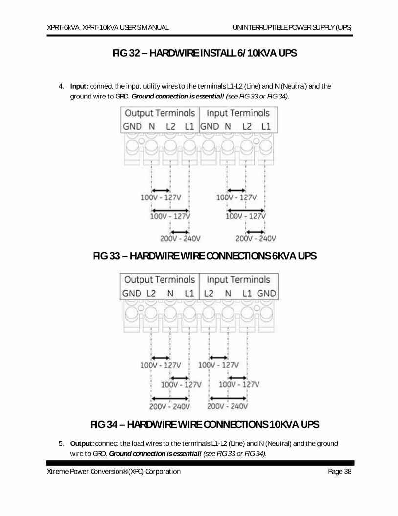
4. Input: connect the input utility wires to the terminals L1-L2 (Line) and N (Neutral) and the ground wire to GRD. Ground connection is essential! (see FIG 33 or FIG 34).
FIG 33 – HARDWIRE WIRE CONNECTIONS 6KVA UPS
FIG 34 – HARDWIRE WIRE CONNECTIONS 10KVA UPS
5. Output: connect the load wires to the terminals L1-L2 (Line) and N (Neutral) and the ground wire to GRD. Ground connection is essential! (see FIG 33 or FIG 34).
XPRT-6kVA, XPRT-10kVA USER’S MANUAL UNINTERRUPTIBLE POWER SUPPLY (UPS)
Xtreme Power Conversion® (XPC) Corporation Page 39
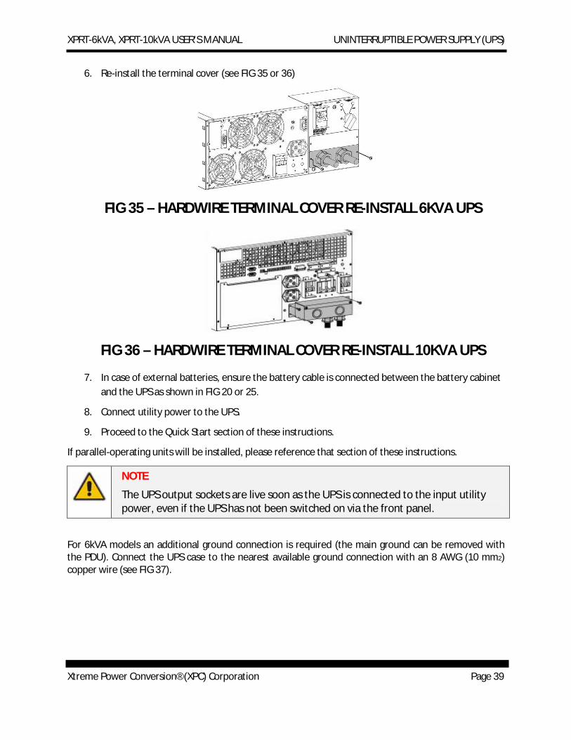
6. Re-install the terminal cover (see FIG 35 or 36)
FIG 35 – HARDWIRE TERMINAL COVER RE-INSTALL 6KVA UPS
FIG 36 – HARDWIRE TERMINAL COVER RE-INSTALL 10KVA UPS
7. In case of external batteries, ensure the battery cable is connected between the battery cabinet and the UPS as shown in FIG 20 or 25.
8. Connect utility power to the UPS.
9. Proceed to the Quick Start section of these instructions.
If parallel-operating units will be installed, please reference that section of these instructions.
NOTE
The UPS output sockets are live soon as the UPS is connected to the input utility power, even if the UPS has not been switched on via the front panel.
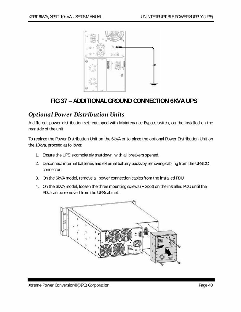
For 6kVA models an additional ground connection is required (the main ground can be removed with the PDU). Connect the UPS case to the nearest available ground connection with an 8 AWG (10 mm2) copper wire (see FIG 37).
XPRT-6kVA, XPRT-10kVA USER’S MANUAL UNINTERRUPTIBLE POWER SUPPLY (UPS)
Xtreme Power Conversion® (XPC) Corporation Page 40
FIG 37 – ADDITIONAL GROUND CONNECTION 6KVA UPS
Optional Power Distribution Units A different power distribution set, equipped with Maintenance Bypass switch, can be installed on the rear side of the unit.
To replace the Power Distribution Unit on the 6kVA or to place the optional Power Distribution Unit on the 10kva, proceed as follows:
1. Ensure the UPS is completely shutdown, with all breakers opened.
2. Disconnect internal batteries and external battery packs by removing cabling from the UPS DC connector.
3. On the 6kVA model, remove all power connection cables from the installed PDU
4. On the 6kVA model, loosen the three mounting screws (FIG 38) on the installed PDU until the PDU can be removed from the UPS cabinet.
XPRT-6kVA, XPRT-10kVA USER’S MANUAL UNINTERRUPTIBLE POWER SUPPLY (UPS)
Xtreme Power Conversion® (XPC) Corporation Page 41
FIG 38 – PDU REMOVAL 6KVA UPS
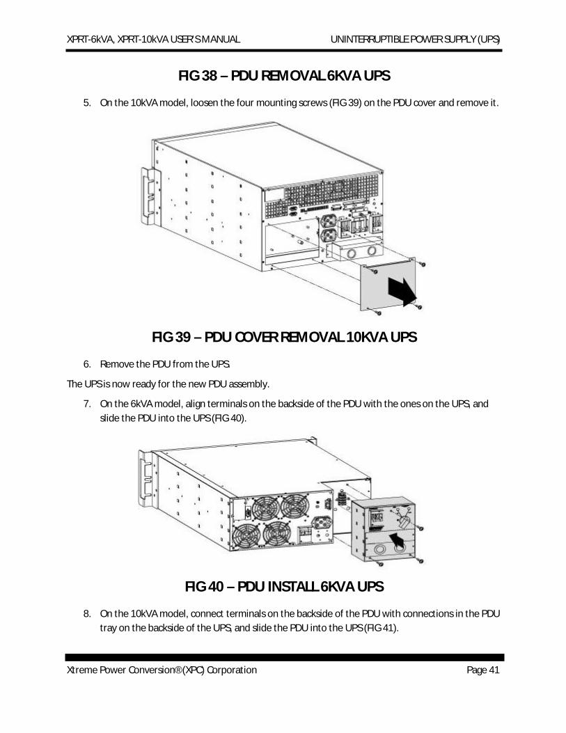
5. On the 10kVA model, loosen the four mounting screws (FIG 39) on the PDU cover and remove it.
FIG 39 – PDU COVER REMOVAL 10KVA UPS
6. Remove the PDU from the UPS.
The UPS is now ready for the new PDU assembly.
7. On the 6kVA model, align terminals on the backside of the PDU with the ones on the UPS, and slide the PDU into the UPS (FIG 40).
FIG 40 – PDU INSTALL 6KVA UPS
8. On the 10kVA model, connect terminals on the backside of the PDU with connections in the PDU tray on the backside of the UPS, and slide the PDU into the UPS (FIG 41).
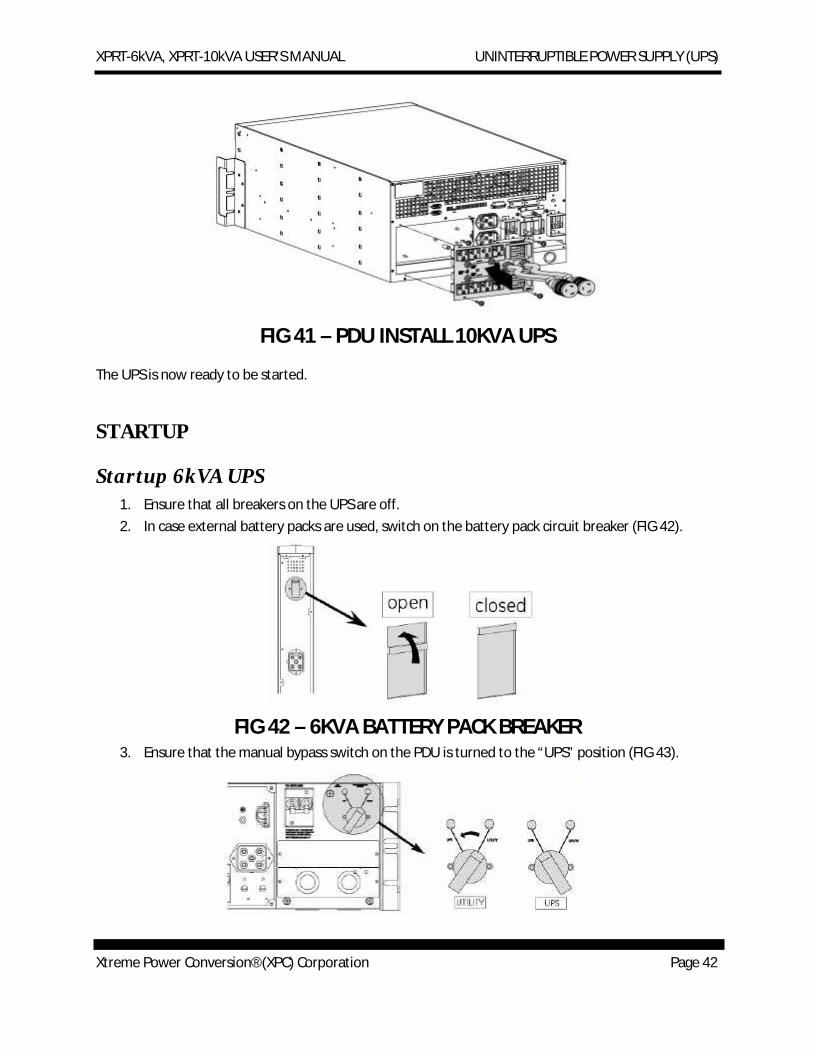
XPRT-6kVA, XPRT-10kVA USER’S MANUAL UNINTERRUPTIBLE POWER SUPPLY (UPS)
Xtreme Power Conversion® (XPC) Corporation Page 42
FIG 41 – PDU INSTALL 10KVA UPS
The UPS is now ready to be started.
STARTUP
Startup 6kVA UPS 1. Ensure that all breakers on the UPS are off. 2. In case external battery packs are used, switch on the battery pack circuit breaker (FIG 42).
FIG 42 – 6KVA BATTERY PACK BREAKER
3. Ensure that the manual bypass switch on the PDU is turned to the “UPS” position (FIG 43).
XPRT-6kVA, XPRT-10kVA USER’S MANUAL UNINTERRUPTIBLE POWER SUPPLY (UPS)
Xtreme Power Conversion® (XPC) Corporation Page 43
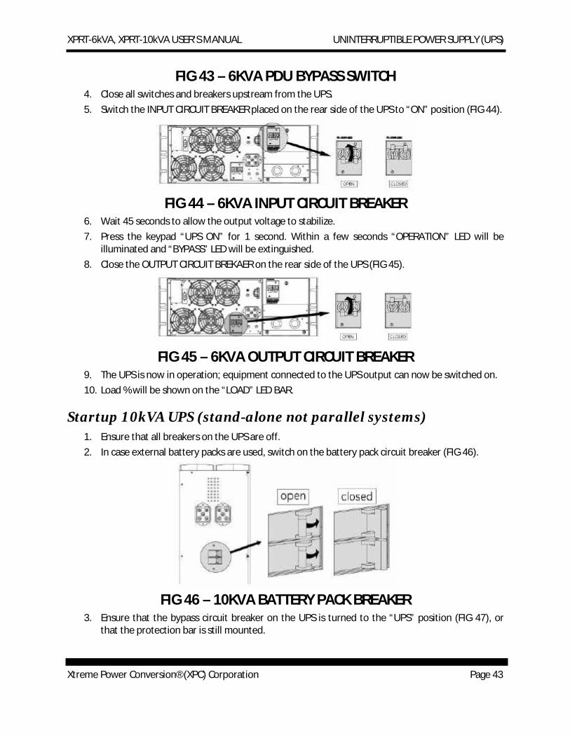
FIG 43 – 6KVA PDU BYPASS SWITCH
4. Close all switches and breakers upstream from the UPS. 5. Switch the INPUT CIRCUIT BREAKER placed on the rear side of the UPS to “ON” position (FIG 44).
FIG 44 – 6KVA INPUT CIRCUIT BREAKER
6. Wait 45 seconds to allow the output voltage to stabilize. 7. Press the keypad “UPS ON” for 1 second. Within a few seconds “OPERATION” LED will be
illuminated and “BYPASS” LED will be extinguished. 8. Close the OUTPUT CIRCUIT BREKAER on the rear side of the UPS (FIG 45).
FIG 45 – 6KVA OUTPUT CIRCUIT BREAKER
9. The UPS is now in operation; equipment connected to the UPS output can now be switched on. 10. Load % will be shown on the “LOAD” LED BAR.
Startup 10kVA UPS (stand-alone not parallel systems) 1. Ensure that all breakers on the UPS are off. 2. In case external battery packs are used, switch on the battery pack circuit breaker (FIG 46).
FIG 46 – 10KVA BATTERY PACK BREAKER
3. Ensure that the bypass circuit breaker on the UPS is turned to the “UPS” position (FIG 47), or that the protection bar is still mounted.
XPRT-6kVA, XPRT-10kVA USER’S MANUAL UNINTERRUPTIBLE POWER SUPPLY (UPS)
Xtreme Power Conversion® (XPC) Corporation Page 44
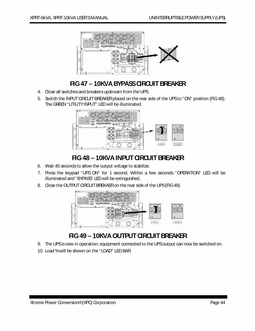
FIG 47 – 10KVA BYPASS CIRCUIT BREAKER
4. Close all switches and breakers upstream from the UPS. 5. Switch the INPUT CIRCUIT BREAKER placed on the rear side of the UPS to “ON” position (FIG 48).
The GREEN “UTILITY INPUT” LED will be illuminated.
FIG 48 – 10KVA INPUT CIRCUIT BREAKER
6. Wait 45 seconds to allow the output voltage to stabilize. 7. Press the keypad “UPS ON” for 1 second. Within a few seconds “OPERATION” LED will be
illuminated and “BYPASS” LED will be extinguished. 8. Close the OUTPUT CIRCUIT BREKAER on the rear side of the UPS (FIG 49).
FIG 49 – 10KVA OUTPUT CIRCUIT BREAKER
9. The UPS is now in operation; equipment connected to the UPS output can now be switched on. 10. Load % will be shown on the “LOAD” LED BAR.
XPRT-6kVA, XPRT-10kVA USER’S MANUAL UNINTERRUPTIBLE POWER SUPPLY (UPS)
Xtreme Power Conversion® (XPC) Corporation Page 45
OPERATION
Normal Operation Conditions 1. The UTILITY INPUT is present and within the tolerance as show in Specification section of this
manual. 2. The UPS is turned ON. 3. The LOAD does not exceed the capacity of the UPS. 4. The OPERATING TEMPERATURE is below alarm level.
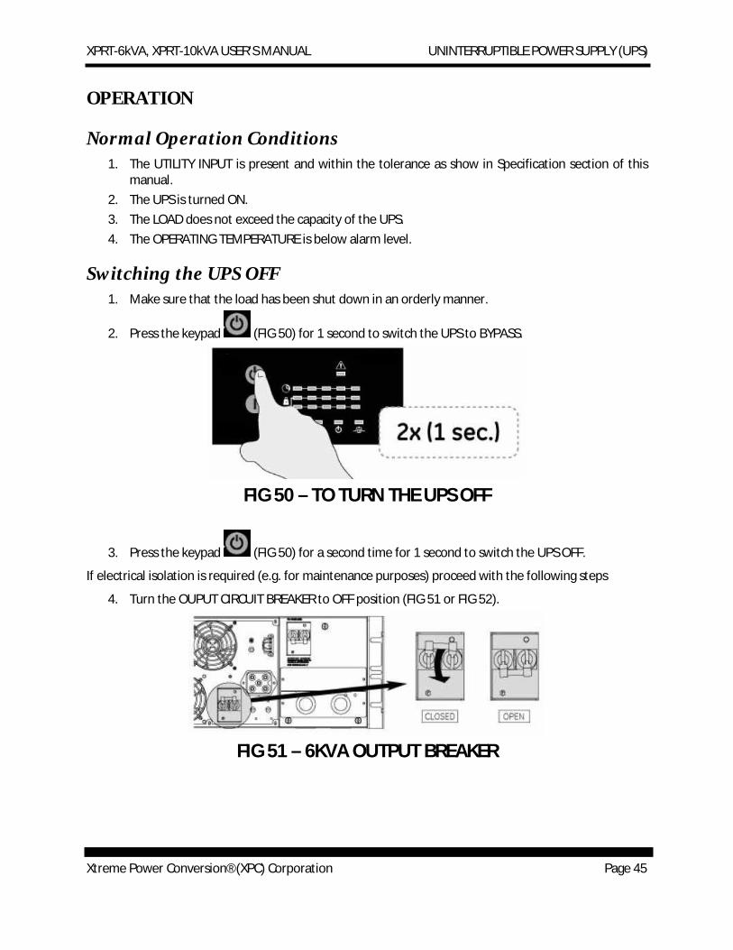
Switching the UPS OFF 1. Make sure that the load has been shut down in an orderly manner.
2. Press the keypad (FIG 50) for 1 second to switch the UPS to BYPASS.
FIG 50 – TO TURN THE UPS OFF
3. Press the keypad (FIG 50) for a second time for 1 second to switch the UPS OFF.
If electrical isolation is required (e.g. for maintenance purposes) proceed with the following steps
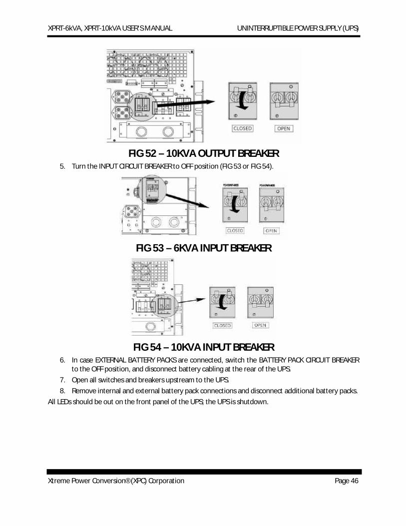
4. Turn the OUPUT CIRCUIT BREAKER to OFF position (FIG 51 or FIG 52).
FIG 51 – 6KVA OUTPUT BREAKER
XPRT-6kVA, XPRT-10kVA USER’S MANUAL UNINTERRUPTIBLE POWER SUPPLY (UPS)
Xtreme Power Conversion® (XPC) Corporation Page 46
FIG 52 – 10KVA OUTPUT BREAKER
5. Turn the INPUT CIRCUIT BREAKER to OFF position (FIG 53 or FIG 54).
FIG 53 – 6KVA INPUT BREAKER
FIG 54 – 10KVA INPUT BREAKER 6. In case EXTERNAL BATTERY PACKS are connected, switch the BATTERY PACK CIRCUIT BREAKER
to the OFF position, and disconnect battery cabling at the rear of the UPS. 7. Open all switches and breakers upstream to the UPS. 8. Remove internal and external battery pack connections and disconnect additional battery packs.
All LEDs should be out on the front panel of the UPS; the UPS is shutdown.
XPRT-6kVA, XPRT-10kVA USER’S MANUAL UNINTERRUPTIBLE POWER SUPPLY (UPS)
Xtreme Power Conversion® (XPC) Corporation Page 47
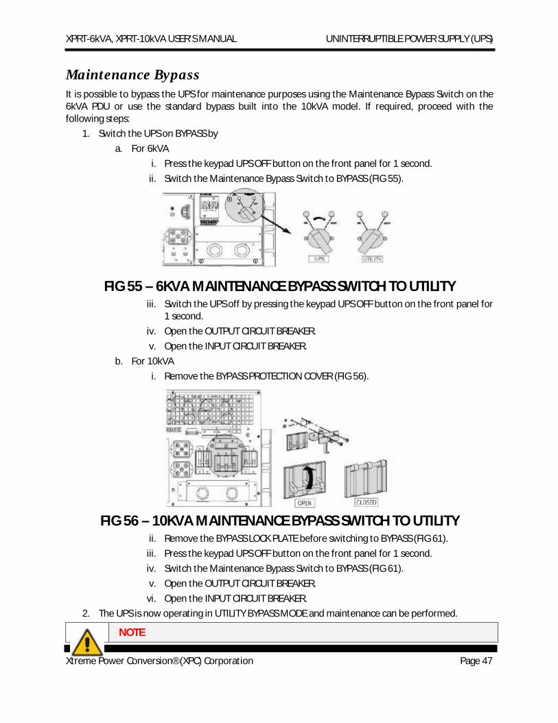
Maintenance Bypass It is possible to bypass the UPS for maintenance purposes using the Maintenance Bypass Switch on the 6kVA PDU or use the standard bypass built into the 10kVA model. If required, proceed with the following steps:
1. Switch the UPS on BYPASS by a. For 6kVA
i. Press the keypad UPS OFF button on the front panel for 1 second. ii. Switch the Maintenance Bypass Switch to BYPASS (FIG 55).
FIG 55 – 6KVA MAINTENANCE BYPASS SWITCH TO UTILITY iii. Switch the UPS off by pressing the keypad UPS OFF button on the front panel for
1 second. iv. Open the OUTPUT CIRCUIT BREAKER. v. Open the INPUT CIRCUIT BREAKER.
b. For 10kVA i. Remove the BYPASS PROTECTION COVER (FIG 56).
FIG 56 – 10KVA MAINTENANCE BYPASS SWITCH TO UTILITY
ii. Remove the BYPASS LOCK PLATE before switching to BYPASS (FIG 61). iii. Press the keypad UPS OFF button on the front panel for 1 second. iv. Switch the Maintenance Bypass Switch to BYPASS (FIG 61). v. Open the OUTPUT CIRCUIT BREAKER.
vi. Open the INPUT CIRCUIT BREAKER. 2. The UPS is now operating in UTILITY BYPASS MODE and maintenance can be performed.
NOTE
XPRT-6kVA, XPRT-10kVA USER’S MANUAL UNINTERRUPTIBLE POWER SUPPLY (UPS)
Xtreme Power Conversion® (XPC) Corporation Page 48
After the UPS is shutdown or in “External Bypass” condition, the residual DC voltage in the unit will be eliminated within 5 minutes.
Once the maintenance is performed on the UPS, resume normal conditions by following these steps:
1. Close the INPUT CIRCUIT BREAKER. 2. Wait 45 seconds to allow the output voltage to stabilize. 3. Press the keypad UPS ON for 1 second. Within a few seconds OPERATION LED will be illuminated
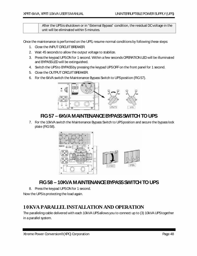
and BYPASS LED will be extinguished. 4. Switch the UPS to BYPASS by pressing the keypad UPS OFF on the front panel for 1 second. 5. Close the OUTPUT CIRCUIT BREAKER. 6. For the 6kVA switch the Maintenance Bypass Switch to UPS position (FIG 57).
FIG 57 – 6KVA MAINTENANCE BYPASS SWITCH TO UPS
7. For the 10kVA switch the Maintenance Bypass Switch to UPS position and secure the bypass lock plate (FIG 58).
FIG 58 – 10KVA MAINTENANCE BYPASS SWITCH TO UPS
8. Press the keypad UPS ON for 1 second. Now the UPS is protecting the load again.
10KVA PARALLEL INSTALLATION AND OPERATION The paralleling cable delivered with each 10kVA UPS allows you to connect up to (3) 10kVA UPS together in a parallel system.
XPRT-6kVA, XPRT-10kVA USER’S MANUAL UNINTERRUPTIBLE POWER SUPPLY (UPS)
Xtreme Power Conversion® (XPC) Corporation Page 49
NOTE
The units connected in parallel must be the same power rating and must have the same output voltage setting (i.e. 120V-120V not 120V-127V).
The paralleling cable delivered with each 10kVA UPS allows you to connect up to (3) 10kVA UPS together in a parallel system.
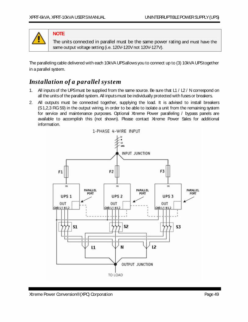
Installation of a parallel system 1. All inputs of the UPS must be supplied from the same source. Be sure that L1 / L2 / N correspond on
all the units of the parallel system. All inputs must be individually protected with fuses or breakers. 2. All outputs must be connected together, supplying the load. It is advised to install breakers
(S 1,2,3 FIG 59) in the output wiring, in order to be able to isolate a unit from the remaining system for service and maintenance purposes. Optional Xtreme Power paralleling / bypass panels are available to accomplish this (not shown). Please contact Xtreme Power Sales for additional information.
XPRT-6kVA, XPRT-10kVA USER’S MANUAL UNINTERRUPTIBLE POWER SUPPLY (UPS)
Xtreme Power Conversion® (XPC) Corporation Page 50
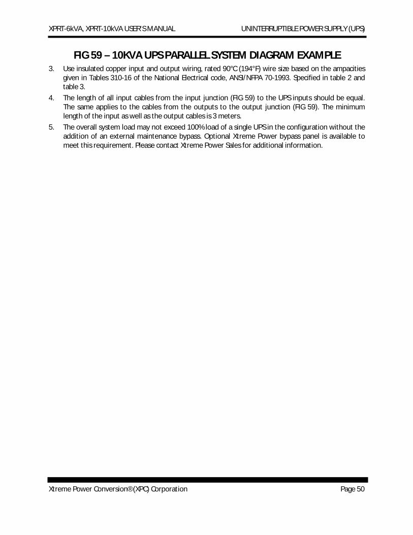
FIG 59 – 10KVA UPS PARALLEL SYSTEM DIAGRAM EXAMPLE
3. Use insulated copper input and output wiring, rated 90°C (194°F) wire size based on the ampacities given in Tables 310-16 of the National Electrical code, ANSI/NFPA 70-1993. Specified in table 2 and table 3.
4. The length of all input cables from the input junction (FIG 59) to the UPS inputs should be equal. The same applies to the cables from the outputs to the output junction (FIG 59). The minimum length of the input as well as the output cables is 3 meters.
5. The overall system load may not exceed 100% load of a single UPS in the configuration without the addition of an external maintenance bypass. Optional Xtreme Power bypass panel is available to meet this requirement. Please contact Xtreme Power Sales for additional information.
XPRT-6kVA, XPRT-10kVA USER’S MANUAL UNINTERRUPTIBLE POWER SUPPLY (UPS)
Xtreme Power Conversion® (XPC) Corporation Page 51
Installing the parallel connection NOTE
Ensure that the UPS is isolated prior to installation; no live input source may be connected to the UPS during the installation procedure. Open all the input/output switches/breakers on the power distribution and ensure no one is able to close them during this installation step.
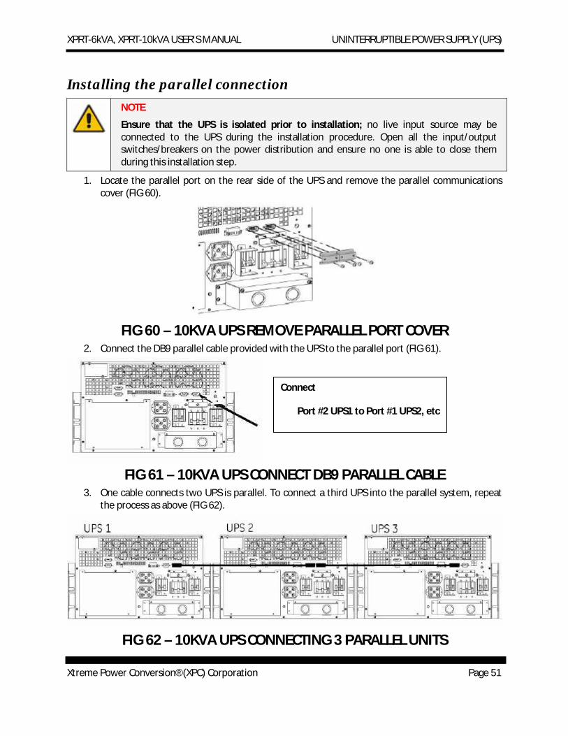
1. Locate the parallel port on the rear side of the UPS and remove the parallel communications cover (FIG 60).
FIG 60 – 10KVA UPS REMOVE PARALLEL PORT COVER
2. Connect the DB9 parallel cable provided with the UPS to the parallel port (FIG 61).
FIG 61 – 10KVA UPS CONNECT DB9 PARALLEL CABLE
3. One cable connects two UPS is parallel. To connect a third UPS into the parallel system, repeat the process as above (FIG 62).
FIG 62 – 10KVA UPS CONNECTING 3 PARALLEL UNITS
Connect
Port #2 UPS1 to Port #1 UPS2, etc
XPRT-6kVA, XPRT-10kVA USER’S MANUAL UNINTERRUPTIBLE POWER SUPPLY (UPS)
Xtreme Power Conversion® (XPC) Corporation Page 52
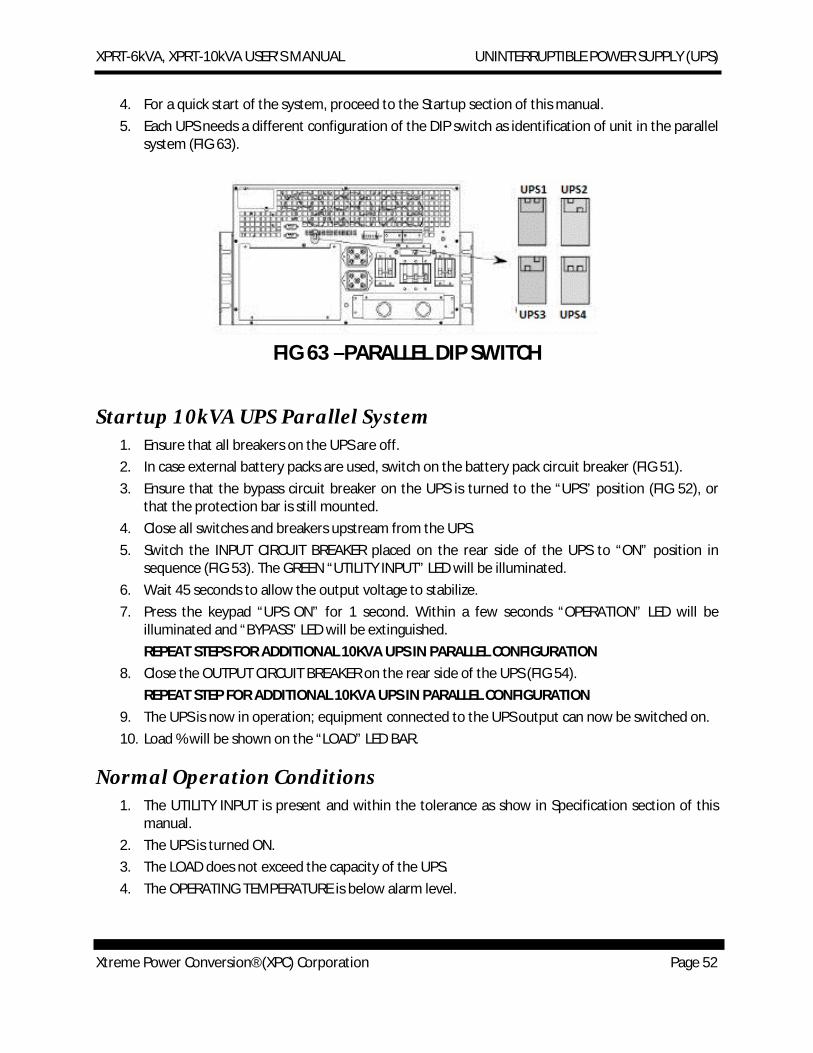
4. For a quick start of the system, proceed to the Startup section of this manual. 5. Each UPS needs a different configuration of the DIP switch as identification of unit in the parallel
system (FIG 63).
FIG 63 –PARALLEL DIP SWITCH
Startup 10kVA UPS Parallel System 1. Ensure that all breakers on the UPS are off. 2. In case external battery packs are used, switch on the battery pack circuit breaker (FIG 51). 3. Ensure that the bypass circuit breaker on the UPS is turned to the “UPS” position (FIG 52), or
that the protection bar is still mounted. 4. Close all switches and breakers upstream from the UPS. 5. Switch the INPUT CIRCUIT BREAKER placed on the rear side of the UPS to “ON” position in
sequence (FIG 53). The GREEN “UTILITY INPUT” LED will be illuminated. 6. Wait 45 seconds to allow the output voltage to stabilize. 7. Press the keypad “UPS ON” for 1 second. Within a few seconds “OPERATION” LED will be
illuminated and “BYPASS” LED will be extinguished. REPEAT STEPS FOR ADDITIONAL 10KVA UPS IN PARALLEL CONFIGURATION
8. Close the OUTPUT CIRCUIT BREAKER on the rear side of the UPS (FIG 54). REPEAT STEP FOR ADDITIONAL 10KVA UPS IN PARALLEL CONFIGURATION
9. The UPS is now in operation; equipment connected to the UPS output can now be switched on. 10. Load % will be shown on the “LOAD” LED BAR.
Normal Operation Conditions 1. The UTILITY INPUT is present and within the tolerance as show in Specification section of this
manual. 2. The UPS is turned ON. 3. The LOAD does not exceed the capacity of the UPS. 4. The OPERATING TEMPERATURE is below alarm level.
XPRT-6kVA, XPRT-10kVA USER’S MANUAL UNINTERRUPTIBLE POWER SUPPLY (UPS)
Xtreme Power Conversion® (XPC) Corporation Page 53
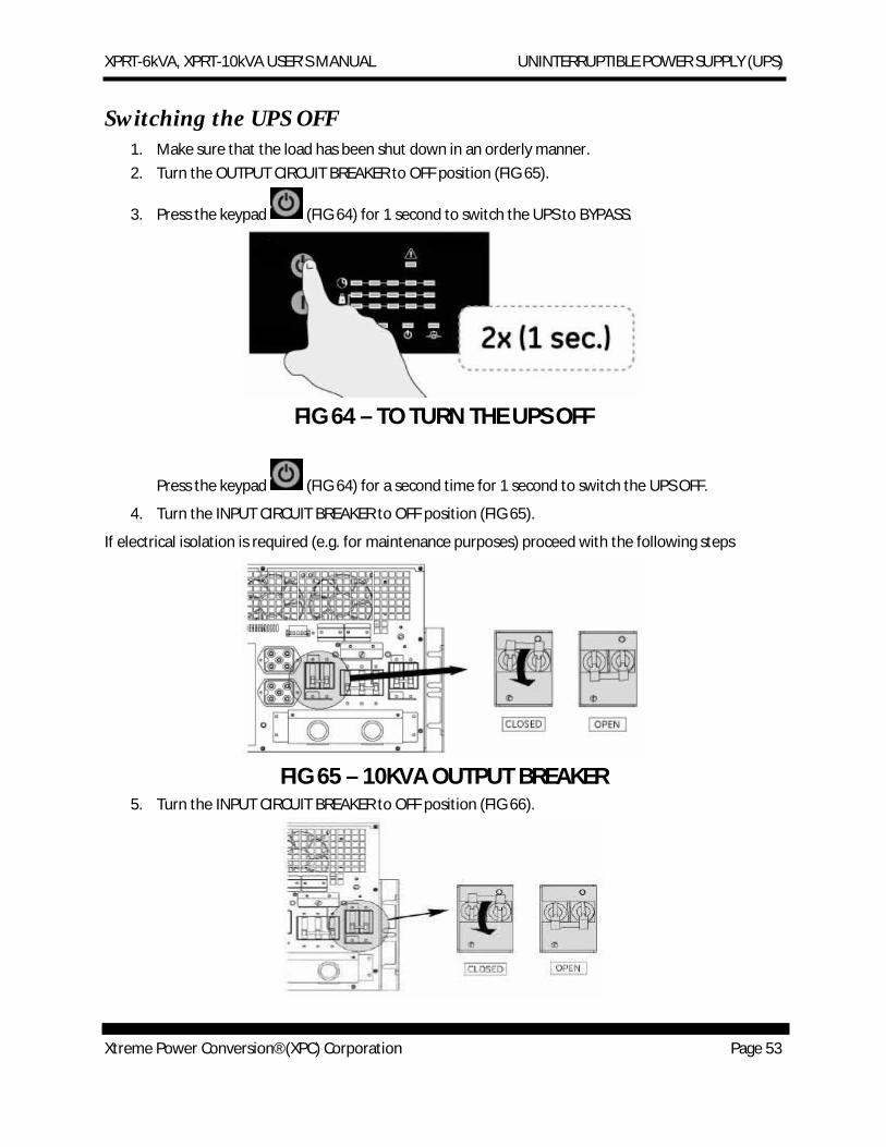
Switching the UPS OFF 1. Make sure that the load has been shut down in an orderly manner. 2. Turn the OUTPUT CIRCUIT BREAKER to OFF position (FIG 65).
3. Press the keypad (FIG 64) for 1 second to switch the UPS to BYPASS.
FIG 64 – TO TURN THE UPS OFF
Press the keypad (FIG 64) for a second time for 1 second to switch the UPS OFF.
4. Turn the INPUT CIRCUIT BREAKER to OFF position (FIG 65).
If electrical isolation is required (e.g. for maintenance purposes) proceed with the following steps
FIG 65 – 10KVA OUTPUT BREAKER
5. Turn the INPUT CIRCUIT BREAKER to OFF position (FIG 66).
XPRT-6kVA, XPRT-10kVA USER’S MANUAL UNINTERRUPTIBLE POWER SUPPLY (UPS)
Xtreme Power Conversion® (XPC) Corporation Page 54
FIG 66 – 10KVA INPUT BREAKER 6. In case EXTERNAL BATTERY PACKS are connected, switch the BATTERY PACK CIRCUIT BREAKER
to the OFF position, and disconnect battery cabling at the rear of the UPS. 7. Open all switches and breakers upstream to the UPS. 8. Remove internal and external battery pack connections and disconnect additional battery packs.
All LEDs should be out on the front panel of the UPS; the UPS is shutdown. REPEAT STEP FOR ADDITIONAL 10KVA UPS IN PARALLEL CONFIGURATION
XPRT-6kVA, XPRT-10kVA USER’S MANUAL UNINTERRUPTIBLE POWER SUPPLY (UPS)
Xtreme Power Conversion® (XPC) Corporation Page 55
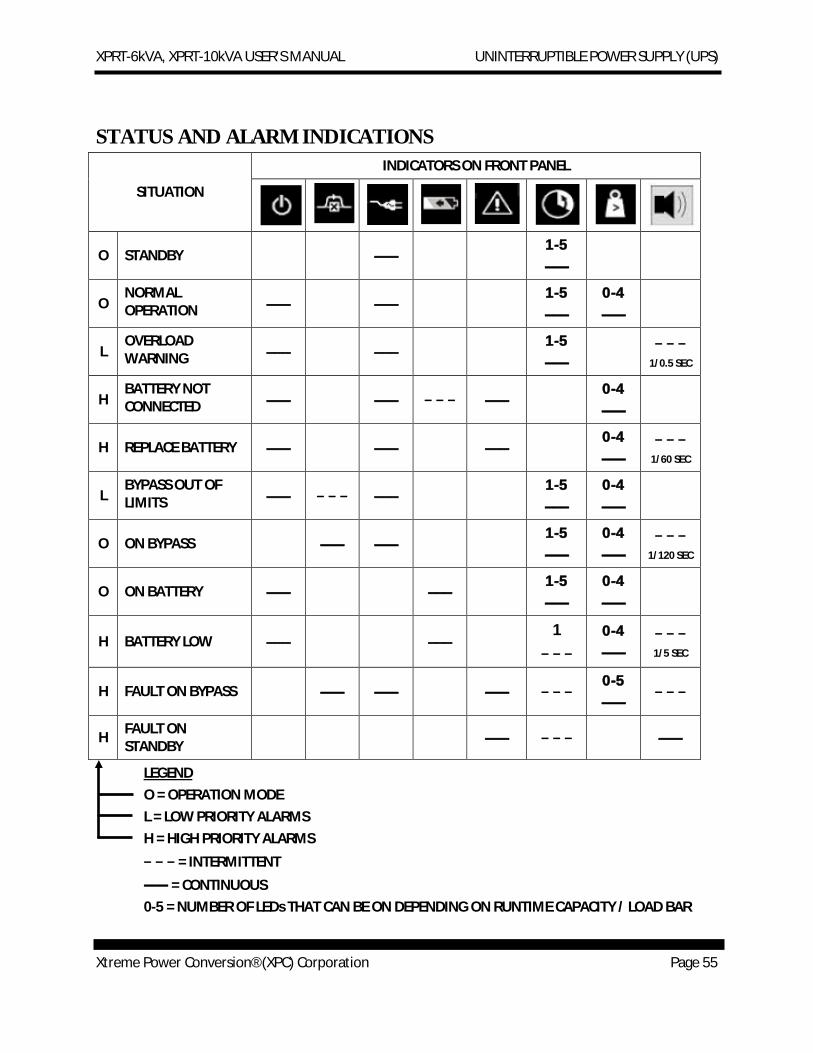
STATUS AND ALARM INDICATIONS
SITUATION
INDICATORS ON FRONT PANEL
O STANDBY ––– 1-5
–––
O NORMAL OPERATION ––– –––
1-5
––– 0-4
–––
L OVERLOAD WARNING ––– –––
1-5
––– − − −
1/0.5 SEC
H BATTERY NOT CONNECTED ––– ––– − − − –––
0-4
–––
H REPLACE BATTERY ––– ––– ––– 0-4
––– − − −
1/60 SEC
L BYPASS OUT OF LIMITS ––– − − − –––
1-5
––– 0-4
–––
O ON BYPASS ––– ––– 1-5
––– 0-4
––– − − −
1/120 SEC
O ON BATTERY ––– ––– 1-5
––– 0-4
–––
H BATTERY LOW ––– ––– 1
− − − 0-4
––– − − − 1/5 SEC
H FAULT ON BYPASS ––– ––– ––– − − − 0-5
––– − − −
H FAULT ON STANDBY ––– − − − –––
LEGEND O = OPERATION MODE L = LOW PRIORITY ALARMS H = HIGH PRIORITY ALARMS
− − − = INTERMITTENT
––– = CONTINUOUS 0-5 = NUMBER OF LEDs THAT CAN BE ON DEPENDING ON RUNTIME CAPACITY / LOAD BAR
XPRT-6kVA, XPRT-10kVA USER’S MANUAL UNINTERRUPTIBLE POWER SUPPLY (UPS)
Xtreme Power Conversion® (XPC) Corporation Page 56
MUTE BUZZER = PRESS BUTTON “|” BRIEFLY
On Bypass The UPS is equipped with an automatic bypass switch. This switch automatically transfers the load to the utility input power if the UPS is unable to deliver the demanded output power due to overload or over temperature. If all 5 LOAD LEDs are illuminated, bypass operation is caused by an overload. If only first runtime LED is illuminated, bypass operation is caused by over temperature. The UPS will switch back to normal operation when the overload has been removed. When temperature drops below alarm level unit can be switched back to normal operation. If a power failure occurs during bypass operation, the UPS will switch to battery if possible, otherwise output power is lost.
On Battery During normal operating conditions, if an input utility failure occurs, the UPS uses the energy stored in the batteries to supply the load. The runtime capacity LED bar will show the remaining time. The UPS will shutdown:
· After the batteries have been discharged (automatic restart if enabled), or · If keypad ‘UPS OFF’ is pressed (restart via front panel required), or · If a ‘UPS shutdown’ command is given by the computer (via UPS monitoring software). Restart
depends on the setting of “auto-restart” function.
Battery Low (end of runtime) If during battery operation, the buzzer starts beeping every 5 seconds and the first LED of the battery charge bar starts blinking, the batteries are nearly discharged: the remaining runtime is less than 2 minutes (default setting, adjustable via the UPS monitoring software). Controlled shutdown of any computer equipment is absolutely necessary when this alarm is raised.
If the UPS operates at 100% load, the shutdown procedure should be completed within 2 minutes after the ‘battery low’ alarm started. If only part of the output capacity of the UPS is used this period can be longer, with aged batteries this period can be shorter.
When the batteries are fully discharged, the UPS is no longer able to supply the connected equipment and eventually output power is lost.
XPRT-6kVA, XPRT-10kVA USER’S MANUAL UNINTERRUPTIBLE POWER SUPPLY (UPS)
Xtreme Power Conversion® (XPC) Corporation Page 57
Bypass Out of Limits The input utility voltage or input utility frequency is outside bypass tolerance but inside UPS input tolerance. Bypass operation is inhibited: if for whatever reason the UPS is not able to deliver the required output, output power is lost. If the input frequency is often out of tolerance – during which bypass operation is inhibited and an alarm is generated – it may be useful to disable bypass function (via UPS monitoring software) after which the unit operates as a UPS without automatic bypass switch.
NOTE
The unit can be used as frequency converter: the input frequency range is 47.5-63Hz, the output frequency is selectable 50/60 Hz, via UPS monitoring software. If the unit is used in this configuration, the bypass function is no longer available.
Overload The demanded power exceeds the nominal capacity of the UPS. The “overload warning” alarm occurs when the load exceeds 150% the UPS will immediately switch to bypass, assuming that the conditions for a transfer to bypass are fulfilled.
If an overload condition between 110-150% persists, the UPS will also switch to bypass operation. In both conditions the “overload” alarm is generated.
During an overload the UPS may automatically switch off within a few minutes (load dependent) and output power is lost:
· if a transfer to bypass is inhibited, or
· if the bypass function has been disabled, or
· if the UPS operates on battery.
To avoid these problems, be absolutely certain that the power demand of the protected equipment is within the limits of the UPS.
Replace Battery Either the batteries are almost chemically worn out or the battery wiring, including the battery fuse, is faulty. If the batteries are aged, they must be replaced as soon as possible to ensure full protection for your equipment. Perhaps the 'replace battery' alarm occurs after a test which you started immediately after installation or after a power failure. In this case the alarm may be incorrect as the batteries have been (partially) discharged during transport or storage or during the power failure. For this reason we advise to execute battery test only after 5 hours on line operation with no input utility failures. This allows the UPS to recharge the batteries.
XPRT-6kVA, XPRT-10kVA USER’S MANUAL UNINTERRUPTIBLE POWER SUPPLY (UPS)
Xtreme Power Conversion® (XPC) Corporation Page 58
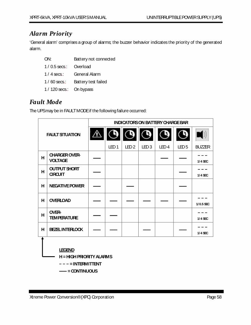
Alarm Priority ‘General alarm’ comprises a group of alarms; the buzzer behavior indicates the priority of the generated alarm.
ON: Battery not connected
1 / 0.5 secs.: Overload
1 / 4 secs.: General Alarm
1 / 60 secs.: Battery test failed
1 / 120 secs.: On bypass
Fault Mode The UPS may be in FAULT MODE if the following failure occurred:
FAULT SITUATION
INDICATORS ON BATTERY CHARGE BAR
LED 1 LED 2 LED 3 LED 4 LED 5 BUZZER
H CHARGER OVER-VOLTAGE ––– ––– ––– − − −
1/4 SEC
H OUTPUT SHORT CIRCUIT ––– ––– − − −
1/4 SEC
H NEGATIVE POWER ––– ––– –––
H OVERLOAD ––– ––– ––– ––– ––– ––– − − − 1/0.5 SEC
H OVER-TEMPERATURE ––– ––– − − −
1/4 SEC
H BEZEL INTERLOCK ––– ––– ––– ––– − − − 1/4 SEC
LEGEND H = HIGH PRIORITY ALARMS
− − − = INTERMITTENT
––– = CONTINUOUS
XPRT-6kVA, XPRT-10kVA USER’S MANUAL UNINTERRUPTIBLE POWER SUPPLY (UPS)
Xtreme Power Conversion® (XPC) Corporation Page 59
In FAULT MODE, the UPS is “forced” on bypass or standby. After having solved the cause of the fault condition, you have to press the UPS OFF button for 0.5 seconds to switch the UPS to normal mode or restart the unit.
Standby In standby mode, the UPS is turned off (output power is lost) and the batteries are being recharged. To put the UPS in Standby, press for 1 second the UPS OFF switch, the UPS switches to bypass. Press one more time UPS OFF switch for 1 second. The UPS is now in standby mode. Most changes to the UPS settings are only possible in bypass or standby mode.
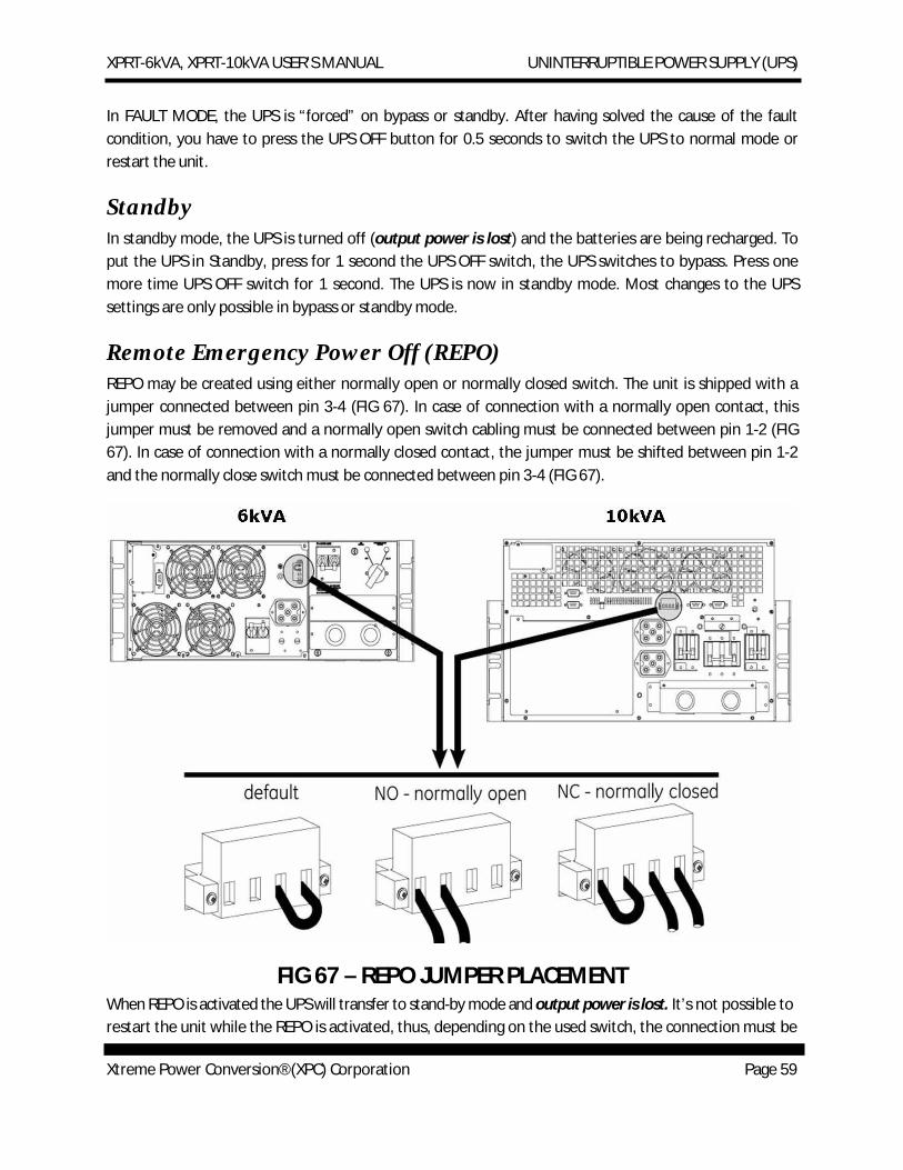
Remote Emergency Power Off (REPO) REPO may be created using either normally open or normally closed switch. The unit is shipped with a jumper connected between pin 3-4 (FIG 67). In case of connection with a normally open contact, this jumper must be removed and a normally open switch cabling must be connected between pin 1-2 (FIG 67). In case of connection with a normally closed contact, the jumper must be shifted between pin 1-2 and the normally close switch must be connected between pin 3-4 (FIG 67).
FIG 67 – REPO JUMPER PLACEMENT
When REPO is activated the UPS will transfer to stand-by mode and output power is lost. It’s not possible to restart the unit while the REPO is activated, thus, depending on the used switch, the connection must be
XPRT-6kVA, XPRT-10kVA USER’S MANUAL UNINTERRUPTIBLE POWER SUPPLY (UPS)
Xtreme Power Conversion® (XPC) Corporation Page 60
restored by closing or opening the contact. Press UPS OFF button 2 times within 4 seconds to be able to restart the unit.
No Load Shutdown If no load shutdown is enabled, if the load is less than 5% and in case of utility failure, the UPS will switch off, avoiding a deep discharge of the batteries and output power is lost. NO LOAD SHUTDOWN is disabled as default. It is possible to enable this feature via the UPS Monitoring Software.
Auto Restart Default enabled AUTO RESTART may be disabled via the UPS Monitoring Software. Auto Restart acts after the UPS has been shut down during an input utility failure.
· If the function is set ENABLED, the UPS will automatically restart when the input utility power returns.
· If the function is set DISABLED, a manual restart either via the front panel or the UPS Monitoring Software is required.
BATTERY MANAGEMENT Maximum battery life and reliability are obtained by the following features:
Battery Connection Test At startup, the UPS performs an automatic test to check that the battery cabling and fuses are properly connected. If the test detects a battery disconnection, the corresponding alarm will be generated.
Quick Battery Test A quick battery test may be launched to check if the batteries are healthy. To start the test, press the UPS ON button for 0.5 seconds when the UPS is in Normal Operation. In case of failure, the corresponding alarm condition will be generated.
Deep Battery Test A deep battery test will update the runtime calculation, and may be started via the UPS Monitoring Software. The test will start only if the battery charge level is higher than 90%, and the load is at least 20% of the nominal rating. The runtime calculation will be updated only if the test can run uninterrupted for a complete battery discharge.
NOTE
When executing a deep battery test, the available runtime in case of input utility failure may be shorter than normal. Don’t execute this test if reduced
XPRT-6kVA, XPRT-10kVA USER’S MANUAL UNINTERRUPTIBLE POWER SUPPLY (UPS)
Xtreme Power Conversion® (XPC) Corporation Page 61
battery runtime is not acceptable.
NOTE
It is possible to reset the battery test, by pressing the UPS OFF switch for 0.5 sec. The UPS will switch to bypass mode.
COMMUNICATION
DB9 Communication Port The RS232 port is a plug-in interface port, which enables advanced communication between the UPS and a computer via a serial cable (FIG 68) and UPS Monitoring Software. The interface port is already operational in standby mode.
FIG 68 – RS232/DB9 COMMUNICATIONS
To change settings of the UPS, we strongly recommend to be sure that the UPS is in standby mode. Some settings can only be changed if the UPS operates in bypass or standby mode.
NOTE
The change of some settings can cause the unit to switch from bypass to standby and output power is lost.
XPRT-6kVA, XPRT-10kVA USER’S MANUAL UNINTERRUPTIBLE POWER SUPPLY (UPS)
Xtreme Power Conversion® (XPC) Corporation Page 62
For more information regarding possible settings, please refer to the HELP manual on the UPS Monitoring Software CD.
SNMP Interface Card (Option) This card allows the data interface to be connected directly to an Ethernet network. The card is fitted into the SNMP Card Slot. For more information, please refer to the user manual that comes with the interface card.
EXTENDED RUNTIME Extended runtime can be obtained by connecting a separate extended battery pack to the UPS. In this case the UPS must be informed about the new total battery capacity to allow a reliable recalculation of the available runtime (via UPS Monitoring Software). Depending of the charge condition of the new batteries the new runtime calculations may temporarily be unreliable.
Additional batteries increase the recharging time for the unit; all other operational information is the same as for standard models. The following table shows runtimes with up to 3 Battery Packs. 1 Battery Pack is the normal configuration.
UNIT LOAD ESTIMATED RUNTIME IN MINUTES
INTERNAL BATTERIES
1 BATTERY PACK
2 BATTERY PACKS
3 BATTERY PACKS
4 BATTERY PACKS
XPRT-6000
10% 75 156 235 313 391 25% 31 75 115 155 195 50% 14 34 58 82 105 75% 8 22 35 50 65
100% 5 14 25 36 47
XPRT-10000
10% 107 251 333 494 590 25% 40 100 160 225 290 50% 16 39 66 92 119 75% 10 24 41 58 75
100% 6 17 28 41 54
XPRT-6kVA, XPRT-10kVA USER’S MANUAL UNINTERRUPTIBLE POWER SUPPLY (UPS)
Xtreme Power Conversion® (XPC) Corporation Page 63
MAINTENANCE
Safety DANGER
When the UPS operates, all parts of the electronics are directly connected to the utility and high voltages are present on all internal parts, including the battery. Even after disconnection from the utility, all parts inside the UPS, including the battery, conduct dangerous voltages (except the COM port output). For your safety, only authorized service personnel may remove the UPS or BP cabinet cover.
General The XPRT Series UPS is virtually maintenance free. Adhere to proper environmental requirements as shown in the Specification, and keep the air inlets / outlets free of dust.
NOTE
Except for battery replacement, refer maintenance and service work to qualified and skilled personnel only.
Recycling the UPS at the End of Service Life NOTE
This product has been designed with respect to the environment, using materials and components respecting eco-design rules. It does not contain CFCs (Carbon Fluorine Chloride) of HCFCs (Halogen Carbon Fluorine Chloride).
The batteries contain lead, which is a harmful substance for the environment.
Proper disposal or recycling of the batteries is required. Refer to your local codes for disposal requirements.
Xtreme Power Conversion Corp, in compliance with environment protection recommends that the UPS equipment, at the end of its service life, must be
XPRT-6kVA, XPRT-10kVA USER’S MANUAL UNINTERRUPTIBLE POWER SUPPLY (UPS)
Xtreme Power Conversion® (XPC) Corporation Page 64
recycled conforming to the local applicable regulations.
Batteries The service life of the batteries in this UPS and BP is from 3 to 5 years, depending on the operating temperature and number of discharge cycles.
A healthy battery is critical to the performance of the UPS. An automatic quick battery test is performed regularly to ensure failsafe operation. When the condition of the battery is critical, a REPLACE BATTERY alarm will be activated. Replace the batteries as soon as possible.
General Guidelines:
· When replace the batteries, use all the same type and size.
· Never short the battery terminals. Shorting may cause the battery to burn. When working with batteries, remove watches, rings or other metal objects, and only use insulated tools.
· Avoid charging batteries in a sealed container.
· Proper disposal of batteries is required. Refer to your local codes for disposal requirements.
· Never dispose of batteries in fire - they may explode.
· Never dismantle or reassemble batteries - their contents (electrolyte) may be extremely toxic. If exposed to electrolyte, wash immediately with plenty of water. If eye contact occurs, flush with water and contact a physician.
Internal Battery Replacement – 6kVA Model In case of battery failure, please proceed with the following steps.
NOTE
During battery replacement the UPS will not be able to support the load if an input utility failure occurs! It is recommended to switch off the load before battery replacement.
1. Remove the UPS front cover from the UPS cabinet by gently pulling it out.
2. Remove the battery grille by loosening the two mounting screws (FIG 69).
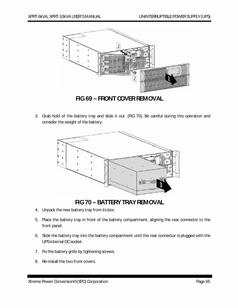
XPRT-6kVA, XPRT-10kVA USER’S MANUAL UNINTERRUPTIBLE POWER SUPPLY (UPS)
Xtreme Power Conversion® (XPC) Corporation Page 65
FIG 69 – FRONT COVER REMOVAL
3. Grab hold of the battery tray and slide it out. (FIG 70). Be careful during this operation and consider the weight of the battery.
FIG 70 – BATTERY TRAY REMOVAL
4. Unpack the new battery tray from its box.
5. Place the battery tray in front of the battery compartment, aligning the rear connector to the front panel.
6. Slide the battery tray into the battery compartment until the rear connector is plugged with the UPS internal DC socket.
7. Fix the battery grille by tightening screws.
8. Re-install the two front covers.

XPRT-6kVA, XPRT-10kVA USER’S MANUAL UNINTERRUPTIBLE POWER SUPPLY (UPS)
Xtreme Power Conversion® (XPC) Corporation Page 66
NOTE To avoid battery malfunction, in case of additional batteries connected, all battery packs have to be replaced! It’s not possible to replace only 1 pack. Avoid connection between new and old battery packs.
Internal Battery Replacement – 10kVA Model In case of battery failure, please proceed with the following steps.
NOTE
During battery replacement the UPS will not be able to support the load if an input utility failure occurs! It is recommended to switch off the load before battery replacement.
1. Remove the UPS front cover from the UPS cabinet by gently pulling it out.
2. Remove the battery grille by loosening the three mounting screws (FIG 71).
FIG 71 – FRONT COVER REMOVAL
3. Disconnect DC cabling from battery tray connectors.
4. Grab hold of the battery trays and slide it out. (FIG 72). Be careful during this operation and consider the weight of the battery.
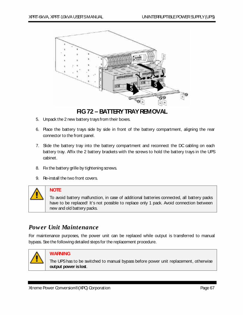
XPRT-6kVA, XPRT-10kVA USER’S MANUAL UNINTERRUPTIBLE POWER SUPPLY (UPS)
Xtreme Power Conversion® (XPC) Corporation Page 67
FIG 72 – BATTERY TRAY REMOVAL
5. Unpack the 2 new battery trays from their boxes.
6. Place the battery trays side by side in front of the battery compartment, aligning the rear connector to the front panel.
7. Slide the battery tray into the battery compartment and reconnect the DC cabling on each battery tray. Affix the 2 battery brackets with the screws to hold the battery trays in the UPS cabinet.
8. Fix the battery grille by tightening screws.
9. Re-install the two front covers.
NOTE To avoid battery malfunction, in case of additional batteries connected, all battery packs have to be replaced! It’s not possible to replace only 1 pack. Avoid connection between new and old battery packs.
Power Unit Maintenance For maintenance purposes, the power unit can be replaced while output is transferred to manual bypass. See the following detailed steps for the replacement procedure.
WARNING The UPS has to be switched to manual bypass before power unit replacement, otherwise output power is lost.
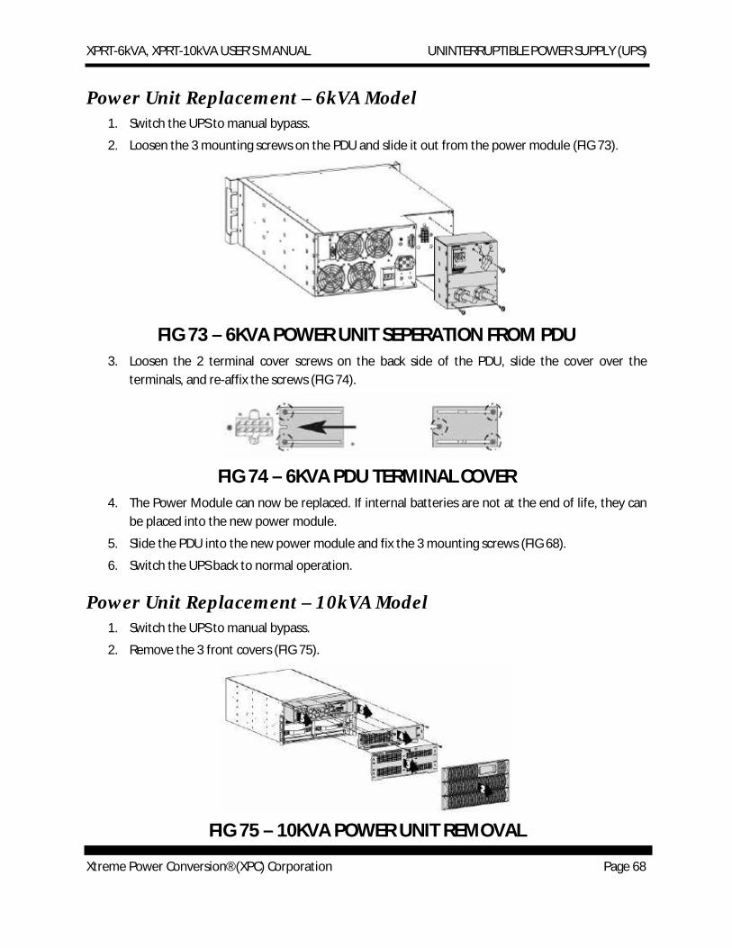
XPRT-6kVA, XPRT-10kVA USER’S MANUAL UNINTERRUPTIBLE POWER SUPPLY (UPS)
Xtreme Power Conversion® (XPC) Corporation Page 68
Power Unit Replacement – 6kVA Model 1. Switch the UPS to manual bypass.
2. Loosen the 3 mounting screws on the PDU and slide it out from the power module (FIG 73).
FIG 73 – 6KVA POWER UNIT SEPERATION FROM PDU
3. Loosen the 2 terminal cover screws on the back side of the PDU, slide the cover over the terminals, and re-affix the screws (FIG 74).
FIG 74 – 6KVA PDU TERMINAL COVER
4. The Power Module can now be replaced. If internal batteries are not at the end of life, they can be placed into the new power module.
5. Slide the PDU into the new power module and fix the 3 mounting screws (FIG 68).
6. Switch the UPS back to normal operation.
Power Unit Replacement – 10kVA Model 1. Switch the UPS to manual bypass.
2. Remove the 3 front covers (FIG 75).
FIG 75 – 10KVA POWER UNIT REMOVAL
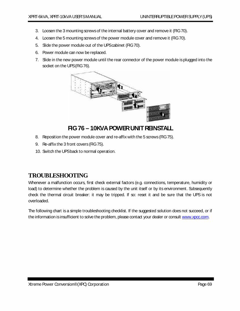
XPRT-6kVA, XPRT-10kVA USER’S MANUAL UNINTERRUPTIBLE POWER SUPPLY (UPS)
Xtreme Power Conversion® (XPC) Corporation Page 69
3. Loosen the 3 mounting screws of the internal battery cover and remove it (FIG 70).
4. Loosen the 5 mounting screws of the power module cover and remove it (FIG 70).
5. Slide the power module out of the UPS cabinet (FIG 70).
6. Power module can now be replaced.
7. Slide in the new power module until the rear connector of the power module is plugged into the socket on the UPS (FIG 76).
FIG 76 – 10KVA POWER UNIT REINSTALL
8. Reposition the power module cover and re-affix with the 5 screws (FIG 75).
9. Re-affix the 3 front covers (FIG 75).
10. Switch the UPS back to normal operation.
TROUBLESHOOTING Whenever a malfunction occurs, first check external factors (e.g. connections, temperature, humidity or load) to determine whether the problem is caused by the unit itself or by its environment. Subsequently check the thermal circuit breaker: it may be tripped. If so: reset it and be sure that the UPS is not overloaded.
The following chart is a simple troubleshooting checklist. If the suggested solution does not succeed, or if the information is insufficient to solve the problem, please contact your dealer or consult www.xpcc.com.
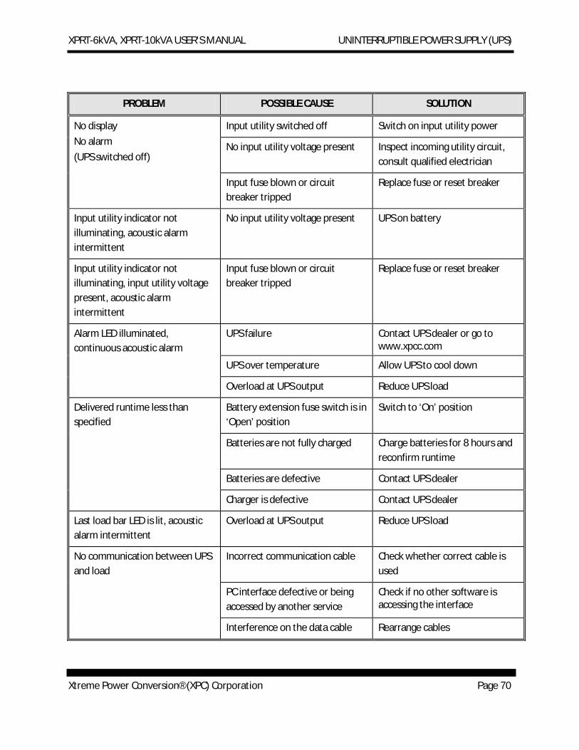
XPRT-6kVA, XPRT-10kVA USER’S MANUAL UNINTERRUPTIBLE POWER SUPPLY (UPS)
Xtreme Power Conversion® (XPC) Corporation Page 70
PROBLEM POSSIBLE CAUSE SOLUTION
No display No alarm (UPS switched off)
Input utility switched off Switch on input utility power
No input utility voltage present Inspect incoming utility circuit, consult qualified electrician
Input fuse blown or circuit breaker tripped
Replace fuse or reset breaker
Input utility indicator not illuminating, acoustic alarm intermittent
No input utility voltage present UPS on battery
Input utility indicator not illuminating, input utility voltage present, acoustic alarm intermittent
Input fuse blown or circuit breaker tripped
Replace fuse or reset breaker
Alarm LED illuminated, continuous acoustic alarm
UPS failure Contact UPS dealer or go to www.xpcc.com
UPS over temperature Allow UPS to cool down
Overload at UPS output Reduce UPS load
Delivered runtime less than specified
Battery extension fuse switch is in ‘Open’ position
Switch to ‘On’ position
Batteries are not fully charged Charge batteries for 8 hours and reconfirm runtime
Batteries are defective Contact UPS dealer
Charger is defective Contact UPS dealer
Last load bar LED is lit, acoustic alarm intermittent
Overload at UPS output Reduce UPS load
No communication between UPS and load
Incorrect communication cable Check whether correct cable is used
PC interface defective or being accessed by another service
Check if no other software is accessing the interface
Interference on the data cable Rearrange cables
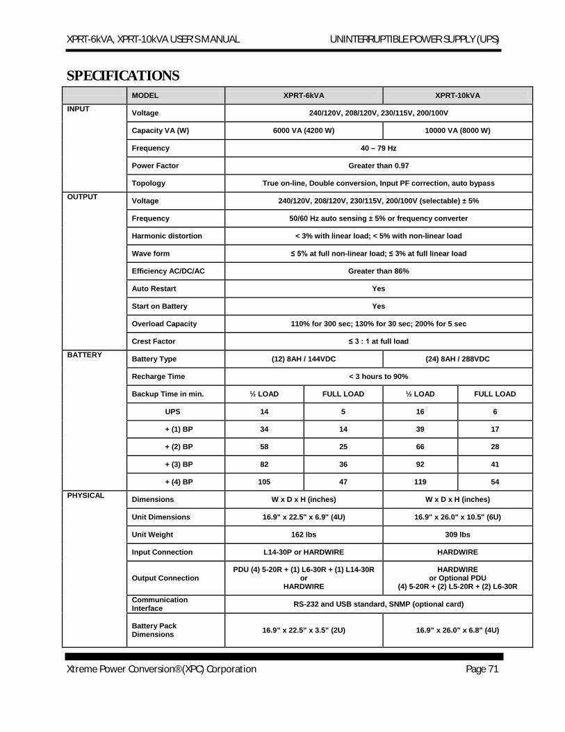
XPRT-6kVA, XPRT-10kVA USER’S MANUAL UNINTERRUPTIBLE POWER SUPPLY (UPS)
Xtreme Power Conversion® (XPC) Corporation Page 71
SPECIFICATIONS MODEL XPRT-6kVA XPRT-10kVA
INPUT Voltage 240/120V, 208/120V, 230/115V, 200/100V
Capacity VA (W) 6000 VA (4200 W) 10000 VA (8000 W)
Frequency 40 – 79 Hz
Power Factor Greater than 0.97
Topology True on-line, Double conversion, Input PF correction, auto bypass
OUTPUT Voltage 240/120V, 208/120V, 230/115V, 200/100V (selectable) ± 5%
Frequency 50/60 Hz auto sensing ± 5% or frequency converter
Harmonic distortion < 3% with linear load; < 5% with non-linear load
Wave form ≤ 5% at full non-linear load; ≤ 3% at full linear load
Efficiency AC/DC/AC Greater than 86%
Auto Restart Yes
Start on Battery Yes
Overload Capacity 110% for 300 sec; 130% for 30 sec; 200% for 5 sec
Crest Factor ≤ 3 : 1 at full load
BATTERY Battery Type (12) 8AH / 144VDC (24) 8AH / 288VDC
Recharge Time < 3 hours to 90%
Backup Time in min. ½ LOAD FULL LOAD ½ LOAD FULL LOAD
UPS 14 5 16 6
+ (1) BP 34 14 39 17
+ (2) BP 58 25 66 28
+ (3) BP 82 36 92 41
+ (4) BP 105 47 119 54
PHYSICAL Dimensions W x D x H (inches) W x D x H (inches)
Unit Dimensions 16.9" x 22.5" x 6.9" (4U) 16.9" x 26.0" x 10.5" (6U)
Unit Weight 162 lbs 309 lbs
Input Connection L14-30P or HARDWIRE HARDWIRE
Output Connection PDU (4) 5-20R + (1) L6-30R + (1) L14-30R
or HARDWIRE
HARDWIRE or Optional PDU
(4) 5-20R + (2) L5-20R + (2) L6-30R
Communication Interface RS-232 and USB standard, SNMP (optional card)
Battery Pack Dimensions 16.9” x 22.5” x 3.5” (2U) 16.9” x 26.0” x 6.8” (4U)
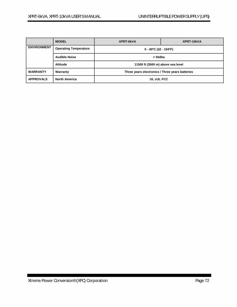
XPRT-6kVA, XPRT-10kVA USER’S MANUAL UNINTERRUPTIBLE POWER SUPPLY (UPS)
Xtreme Power Conversion® (XPC) Corporation Page 72
MODEL XPRT-6kVA XPRT-10kVA
ENVIRONMENT Operating Temperature 0 - 40ºC (32 - 104ºF) Audible Noise < 55dba
Altitude 11500 ft (3500 m) above sea level
WARRANTY Warranty Three years electronics / Three years batteries
APPROVALS North America UL cUL FCC
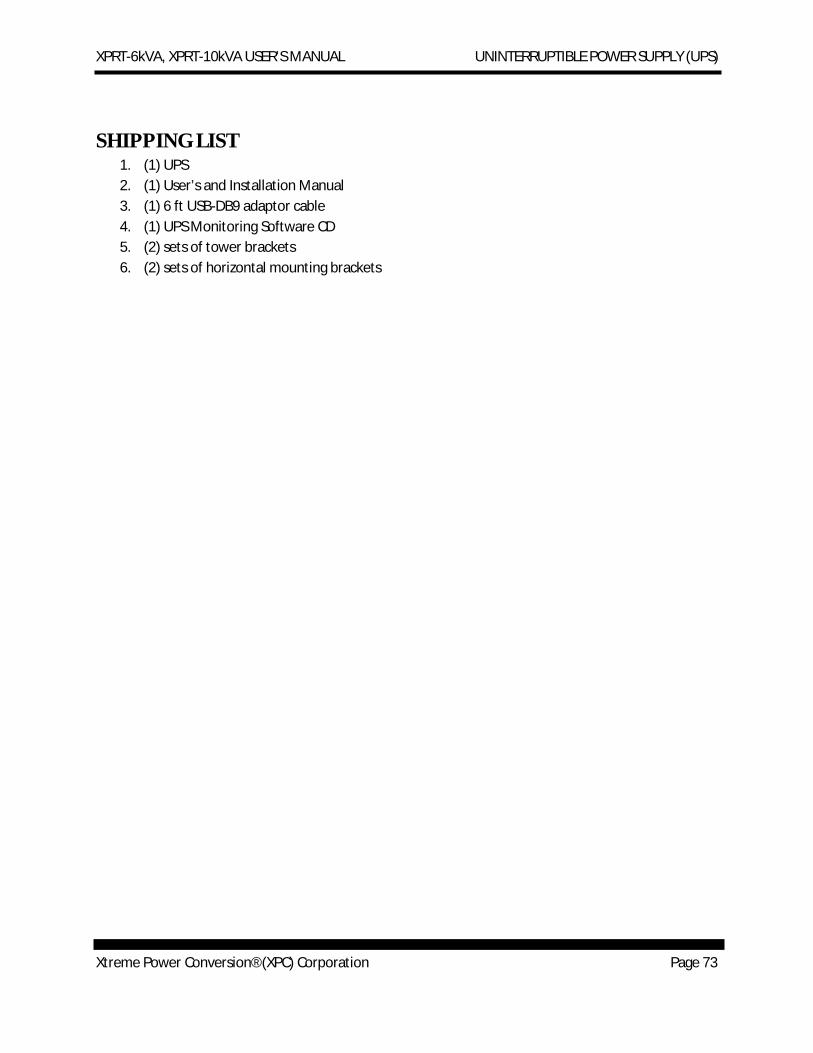
XPRT-6kVA, XPRT-10kVA USER’S MANUAL UNINTERRUPTIBLE POWER SUPPLY (UPS)
Xtreme Power Conversion® (XPC) Corporation Page 73
SHIPPING LIST 1. (1) UPS 2. (1) User’s and Installation Manual 3. (1) 6 ft USB-DB9 adaptor cable 4. (1) UPS Monitoring Software CD 5. (2) sets of tower brackets 6. (2) sets of horizontal mounting brackets
XPRT-6kVA, XPRT-10kVA USER’S MANUAL UNINTERRUPTIBLE POWER SUPPLY (UPS)
Xtreme Power Conversion® (XPC) Corporation Page 74
OBTAINING SERVICE
If the UPS requires Service:
1. Use the TROUBLESHOOTING section in this manual to eliminate obvious causes. 2. Verify there are no circuit breakers tripped. 3. Call your dealer for assistance. If you cannot reach your dealer, or if they cannot resolve the
problem, call Xtreme Power Conversion Corp Technical Support at 800.582.4524 or 720.292.1217. Technical support inquires can also be made at [email protected]. Please have the following information available BEFORE calling the Technical Support Department:
a. Your name and address. b. The serial number of the unit. c. Where and when the unit was purchased. d. All of the model information about your UPS. e. Any information on the failure, including LED’s that may or may not be illuminated. f. A description of the protected equipment, including model numbers if possible.
A technician will ask you for the above information and, if possible, help solve your problem over the phone. In the event that the unit requires factory service, the technician will issue you a Return Material Authorization number (RMA).
If you are returning the UPS to Xtreme Power for service, please follow these procedures:
1. Pack the UPS in its original packaging. If the original packaging is no longer available, as the Technical Support Technician about obtaining a replacement set of packaging material. It is important to pack the UPS properly in order to avoid damage in transit. Never use Styrofoam beads for a packing material.
2. Include a letter with your name, address, daytime phone number, RMA number, a copy of your original sales receipt, and a brief description of the problem.
3. Mark the RMA number on the outside of all packages. Xtreme Power cannot accept any package without the RMA number marked on the outside of the boxes.
4. Return the UPS by insured, prepaid carrier to the address provided by the Technician.
Refer to the Warranty statements in this manual for additional details on what is covered.
XPRT-6kVA, XPRT-10kVA USER’S MANUAL UNINTERRUPTIBLE POWER SUPPLY (UPS)
Xtreme Power Conversion® (XPC) Corporation Page 75
XTREME POWER CONVERSION® (XPC) CORPORATION LIMITED WARRANTY
Xtreme Power Conversion (XPC) Corporation warrants Xtreme Power Conversion equipment, when properly applied and operated within specified conditions, against faulty materials or workmanship (excluding batteries) for a period of three years for XPRT-Series products from the date of purchase. XPC Corporation warrants internal batteries for a period of three years from the date of purchase. For equipment sites within the United States and Canada, this warranty covers repair or replacement, at the sole discretion of XPC Corporation. The customer is responsible for the costs of shipping the defective product to XPC Corporation. XPC Corporation will pay for ground shipment of the repaired or replacement product. This warranty applies only to the original purchaser.
If equipment provided by XPC Corporation is found to be Dead-on-Arrival (DOA), XPC Corporation will be responsible for the costs of shipping product to and returning equipment from the customer in a timely manner as agreed to with the customer, once the customer has requested and received a Return Material Authorization (RMA) number. DOA equipment is defined as equipment that does not properly function according to user documentation when initially received and connected in conjunction with proper procedures as shown in the user documentation or via support provided by XPC Corporation personnel or authorized agents.
This warranty shall be void if (a) the equipment is repaired or modified by anyone other than XPC Corporation or a XPC Corporation approved third party; (b) the equipment is damaged by the customer, is improperly used or stored, is subjected to an adverse operating environment, or is operated outside the limits of its electrical specifications; or (c) the equipment has been used or stored in a manner contrary to the equipment’s operating manual, intended use or other written instructions. Any technical advice furnished by XPC Corporation or a XPC Corporation authorized representative before or after delivery with regard to the use or application of Xtreme Power Conversion equipment is furnished on the basis that it represents XPC Corporations best judgment under the situation and circumstances, but it is used at the recipient’s sole risk.
EXCEPT AS STATED ABOVE, XPC Corporation DISCLAIMS ALL WARRANTIES, EXPRESSED OR IMPLIED, INCLUDING WARRANTIES OF MERCHANTABILITY AND FITNESS FOR A PARTICULAR PURPOSE.
EXCEPT AS STATED ABOVE, IN NO EVENT WILL XPC Corporation BE LIABLE FOR DIRECT, INDIRECT, SPECIAL, INCIDENTAL, OR CONSEQUENTIAL DAMAGES ARISING OUT OF THE USE OF Xtreme Power Conversion EQUIPMENT, including but not limited to, any costs, lost profits or revenue, loss of equipment, loss of use of equipment, loss of software, loss of data, cost of substitutes, or claims by third parties..Purchaser’s sole and exclusive remedy for breach of any warranty, expressed or implied, concerning Xtreme Power Conversion equipment, and the only obligation of XPC Corporation under this warranty, shall be the repair or replacement of defective equipment, components, or parts; or, at XPC Corporations sole discretion, refund of the purchase price or substitution of an equivalent replacement product.
XPRT-6kVA, XPRT-10kVA USER’S MANUAL UNINTERRUPTIBLE POWER SUPPLY (UPS)
Xtreme Power Conversion® (XPC) Corporation Page 76
XTREME POWER CONVERSION® LOAD PROTECTION POLICY For Standard EPC 120, 208 and 240 Volt Products used in the United States and Canada
THIS POLICY IS NOT A WARRANTY. REFER TO THE XPC CORPORATION, INC. LIMITED WARRANTY FOR INFORMATION CONCERNING THE WARRANTY FOR YOUR XPC PRODUCT. THE LIMITATIONS AND CONDITIONS CONTAINED IN THIS
POLICY DO NOT AFFECT THE TERMS OF THE XPC LIMITED WARRANTY. Definitions:
1. “Product” means an XPC Standard EPC 120, 208, or 240 Volt power protection device that is used in the United States and Canada. This policy does not include custom manufactured products.
2. “Power Disturbance” means an AC power line transient (telephone line, local Area Network or CATV transients, if applicable), spike or surge.
3. “Fair Market Value” of damaged Connected Equipment as determined by XPC shall be the lower of (a) the average price the same or similar items are being sold for on eBay, (b) the price list of Orion Blue Book (or if such price list is no longer published, a published or announced price list reasonably selected by XPC), (c) the lowest price the same or similar items can be purchased for in the United States or (d) the total amount of all payment(s) you have or are entitled to receive from insurance, other warranties, extended warranties, a legal liability claim or from other sources or persons for the damaged Connected Equipment.
4. “Initial Purchaser,” “Purchaser” or “You” means the person or entity that originally purchased the Product from an authorized reseller or distributor of XPC Products.
The Initial Purchaser of this Product is protected, for the term of the XPC Limited Warranty, against certain losses caused by a Power Disturbance for properly connected electronic equipment (referred to as the "Connected Equipment") subject to certain terms and conditions provided below.
This policy applies only to the original purchaser of the Product. If the Product is transferred or sold to another person or entity, this policy is void.
Load Protection Policy Dollar and Period Limits
For purchasers that meet the qualifications and conditions set forth in this policy, XPC will provide reimbursement (cost of repair or fair market value as determined by XPC) during the period limits and up to the dollar limits stated as follows:
Product Dollar limit Period of Coverage XVT 25,000 Term of XPC Limited Warranty
NXRT-XPRT- 6 kva 50,000 Term of XPC Limited Warranty
NXRT-XPRT-10 kva 50,000 Term of XPC Limited Warranty This Load Protection Policy is not deemed "first dollar" coverage. XPC’s obligation is reduced by any amounts that the Initial Purchaser is entitled to recover, from other sources regarding the Connected Equipment, including, but not limited to, insurance, other warranty, extended warranty, or legal liability, regardless of whether or not the Initial Purchaser makes a claim for recovery.
Eligibility for coverage under the Load Protection Policy
1. The Product must be registered on the XPC website, www.xtremepowerconversion.com, within 10 days of purchase. All required information must be provided, and Purchaser should retain a copy for Purchaser’s records. When registering on the website, Purchaser must list all connected equipment that is directly connected to the product. Only those devices registered in that manner will be covered.
2. All Connected Equipment must be UL or CSA approved. 3. The Product must be plugged into a properly wired and grounded outlet. Use of input surge devices, extension cords,
adapters, ground wires, or electrical connections not manufactured by XPC voids the XPC Load Protection Policy. No other surge protection device may be connected to the output sockets of the Product. The installation must comply with all applicable electrical and safety codes set forth pursuant to the NEC.
4. The Product must have undeniable physical evidence of a Power Disturbance that directly and proximately caused the damage;
5. The Connected Equipment must have been damaged by a Power Disturbance on a properly installed, grounded, and National Electric Code, ("NEC"), code-compliant 120, 208, 240-volt AC power line in the United States or Canada, by a Power Disturbance on standard telephone land line or PBX telephone equipment line that is properly installed and connected to an RJ11 port on the Product; or by a Power Disturbance on a standard Local Area Network connection that is properly installed and connected to an RJ45 port on the Product and (d) is directly plugged into, and properly connected to, the Product in its original condition which was properly operated when a Power Disturbance passed through the Product and (i) exhausts the protection capacity of the Product or (ii) damages the Product.
XPRT-6kVA, XPRT-10kVA USER’S MANUAL UNINTERRUPTIBLE POWER SUPPLY (UPS)
Xtreme Power Conversion® (XPC) Corporation Page 77
6. The Load Protection Policy does not apply if the Product has been operated in a failure mode or not in compliance with XPC operating instructions in the Product user's manual, or if the Connected Equipment has not been operated in compliance with the instructions and manuals of its manufacturer/vendor.
7. This policy is null and void if, XPC determines, in its sole discretion, that the Product has been tampered with or altered in any way.
What is Not Covered Under the Load Protection Policy:
The following damage is not covered by this Policy:
1. Restoration of lost data and reinstallation of software. 2. Damage from a cause other than AC power-line transients, except for damage due to telephone line, Local Area
Network, or CATV transients, which is covered only if the Product offers such protection. 3. DAMAGE CAUSED BY FAILURE TO PROVIDE A SUITABLE INSTALLATION ENVIRONMENT FOR THE
PRODUCT (INCLUDING, BUT NOT LIMITED TO, LACK OF A PROPER SAFETY GROUND). 4. Damage caused by the use of the Product for purposes other than those for which it was designed. 5. Damage caused by accidents, or natural disasters, including but not limited to, fire, flood, and wind. 6. Damage caused by abuse, misuse, alteration, modification, or negligence. 7. Any labor costs or travel, room and board expenses associated with the repair and/or restoration of lost or damaged
hardware, software or data.
EXCEPT AS EXPRESSLY PROVIDED IN THIS POLICY, XPC SHALL NOT BE LIABLE FOR ANY DAMAGES WHATSOEVER, INCLUDING, BUT NOT LIMITED TO, DIRECT, INDIRECT, SPECIAL, INCIDENTAL, CONSEQUENTIAL, OR MULTIPLE DAMAGES ARISING OUT OF THE USE OF THE PRODUCT OR DAMAGE TO THE CONNECTED EQUIPMENT, REGARDLESS OF THE LEGAL THEORY ON WHICH SUCH CLAIM IS BASED, EVEN IF ADVISED OF THE POSSIBILITY OF SUCH DAMAGE. SUCH DAMAGES INCLUDE, BUT ARE NOT LIMITED TO, LOSS OF PROFITS, LOSS OF SAVINGS OR REVENUE, LOSS OF USE OF THE PRODUCT OR THE CONNECTED EQUIPMENT OR ANY ASSOCIATED EQUIPMENT, LOSS OF SOFTWARE, COST OF CAPITAL, COST OF ANY SUBSTITUTE EQUIPMENT, FACILITIES OR SERVICES, DOWNTIME, THE CLAIMS OF THIRD PARTIES, INCLUDING CUSTOMERS, AND INJURY TO PROPERTY.
Submitting a Load Protection Policy Claim:
1. Any claim under the Load Protection Policy must be made within 10 days of the date of alleged damage to the Connected Equipment.
2. Call the XPC technical support department at 1-800- 582-4524 and obtain a Load Protection Policy Returned Material Authorization (RMA) number. Have information on all applicable insurance or other resources of recovery/payment that are available to the Initial Purchaser and the name of the power utility supplier for the location of the Connected Equipment. XPC will forward to you a Load Protection Policy claims form, which must be completed and filed with XPC within 30 days.
a. Mark the Load Protection Policy RMA number on the Product you are returning. b. Pack the Product in its original packaging or similar packing materials if the original packaging has been
discarded. Enclose the completed Load Protection Policy claim form and a copy of your original sales receipt for the Product in the box.
c. Mark the RMA number clearly on the outside of the box. d. Ship the Product (one-way shipping charges paid by you) to:
XPC Corporation 230 Yuma Street
Denver, Colorado 80439 Attn: LPP RMA#
3. XPC will evaluate the Product to determine its level of functionality, and will examine the Product for evidence of damage from a Power Disturbance..
a. If XPCs' evaluation provides no evidence of damage from a Power Disturbance, XPC will send to the Purchaser (i) a report summarizing the tests performed and (ii) a rejection of claim notice.
b. If the Product shows evidence of damage from a Power Disturbance, XPC will request that all Connected Equipment for which a Load Protection Policy claim has been submitted, be sent for evaluation to either XPC or an authorized service center. If it is determined that the Connected Equipment has been damaged by a Power Disturbance, XPC will, in its sole discretion, issue payment to you for either the cost of repair of the Connected Equipment or the Fair Market Value of the damaged Connected Equipment, up to the dollar limits stated above. XPC reserves the right to require you to transfer title and deliver the Connected Equipment to XPC if it chooses to reimburse you for the fair market value of the Connected Equipment. XPCs' maximum liability shall be reduced to reflect all such other payments or sources of recovery, whether applied for or not.
4. If XPC issues payment to you to have the Connected Equipment repaired, the repair must be performed at a service center that is authorized by the manufacturer of the Connected Equipment. XPC reserves the right to contact the
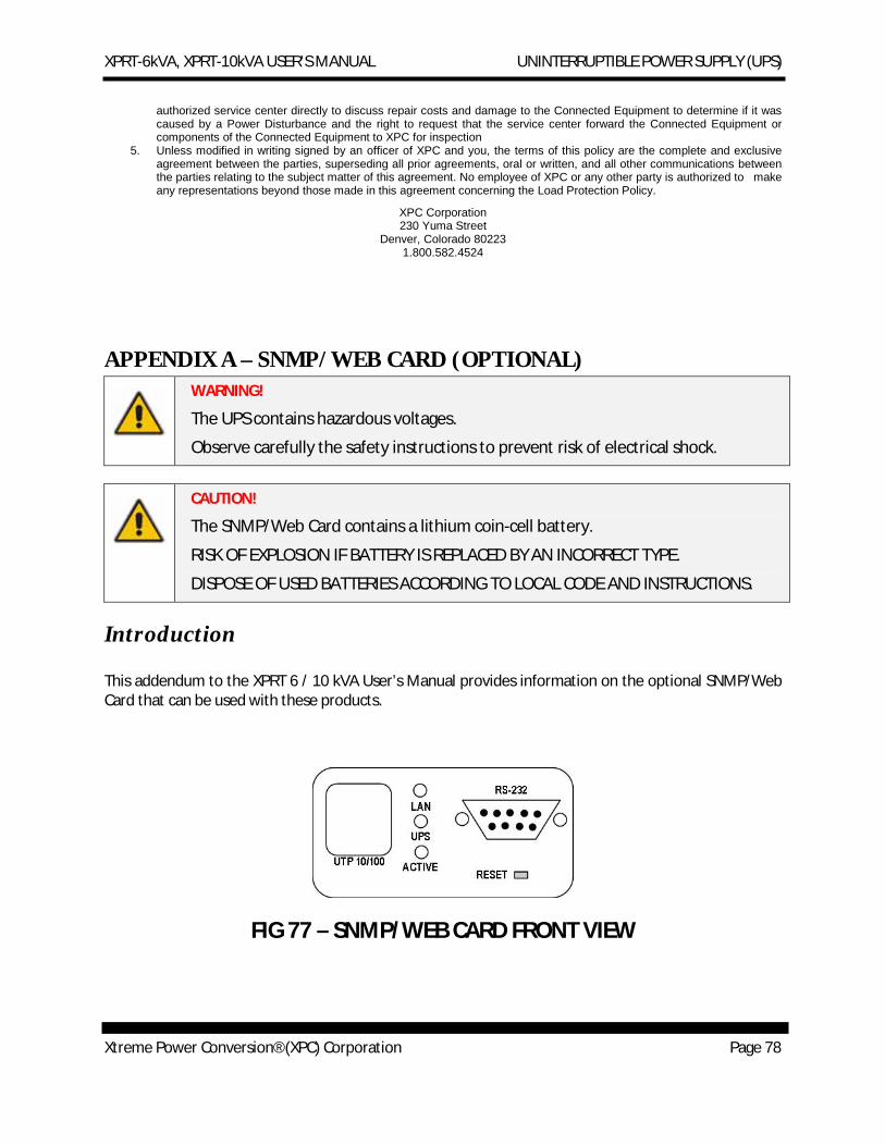
XPRT-6kVA, XPRT-10kVA USER’S MANUAL UNINTERRUPTIBLE POWER SUPPLY (UPS)
Xtreme Power Conversion® (XPC) Corporation Page 78
authorized service center directly to discuss repair costs and damage to the Connected Equipment to determine if it was caused by a Power Disturbance and the right to request that the service center forward the Connected Equipment or components of the Connected Equipment to XPC for inspection
5. Unless modified in writing signed by an officer of XPC and you, the terms of this policy are the complete and exclusive agreement between the parties, superseding all prior agreements, oral or written, and all other communications between the parties relating to the subject matter of this agreement. No employee of XPC or any other party is authorized to make any representations beyond those made in this agreement concerning the Load Protection Policy.
XPC Corporation 230 Yuma Street
Denver, Colorado 80223 1.800.582.4524
APPENDIX A – SNMP/WEB CARD (OPTIONAL) WARNING!
The UPS contains hazardous voltages.
Observe carefully the safety instructions to prevent risk of electrical shock.
CAUTION!
The SNMP/Web Card contains a lithium coin-cell battery.
RISK OF EXPLOSION IF BATTERY IS REPLACED BY AN INCORRECT TYPE.
DISPOSE OF USED BATTERIES ACCORDING TO LOCAL CODE AND INSTRUCTIONS.
Introduction
This addendum to the XPRT 6 / 10 kVA User’s Manual provides information on the optional SNMP/Web Card that can be used with these products.
FIG 77 – SNMP/WEB CARD FRONT VIEW
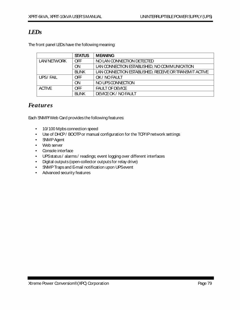
XPRT-6kVA, XPRT-10kVA USER’S MANUAL UNINTERRUPTIBLE POWER SUPPLY (UPS)
Xtreme Power Conversion® (XPC) Corporation Page 79
LEDs
The front panel LEDs have the following meaning:
STATUS MEANING LAN/NETWORK OFF NO LAN CONNECTION DETECTED
ON LAN CONNECTION ESTABLISHED, NO COMMUNICATION BLINK LAN CONNECTION ESTABLISHED, RECEIVE OR TRANSMIT ACTIVE
UPS / FAIL OFF OK / NO FAULT ON NO UPS CONNECTION
ACTIVE OFF FAULT OF DEVICE BLINK DEVICE OK / NO FAULT
Features
Each SNMP/Web Card provides the following features:
· 10/100 Mpbs connection speed · Use of DHCP / BOOTP or manual configuration for the TCP/IP network settings · SNMP Agent · Web server · Console interface · UPS status / alarms / readings; event logging over different interfaces · Digital outputs (open-collector outputs for relay drive) · SNMP Traps and E-mail notification upon UPS event · Advanced security features
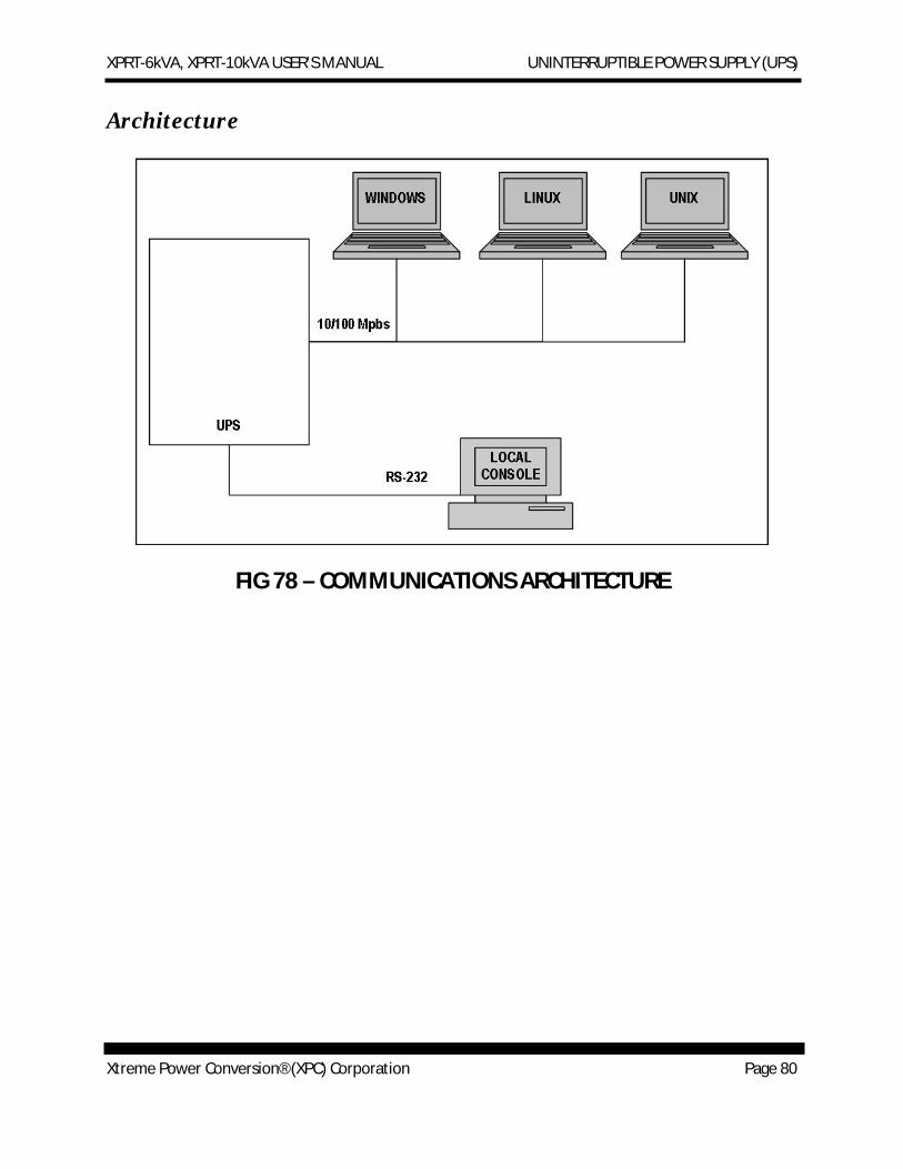
XPRT-6kVA, XPRT-10kVA USER’S MANUAL UNINTERRUPTIBLE POWER SUPPLY (UPS)
Xtreme Power Conversion® (XPC) Corporation Page 80
Architecture
FIG 78 – COMMUNICATIONS ARCHITECTURE
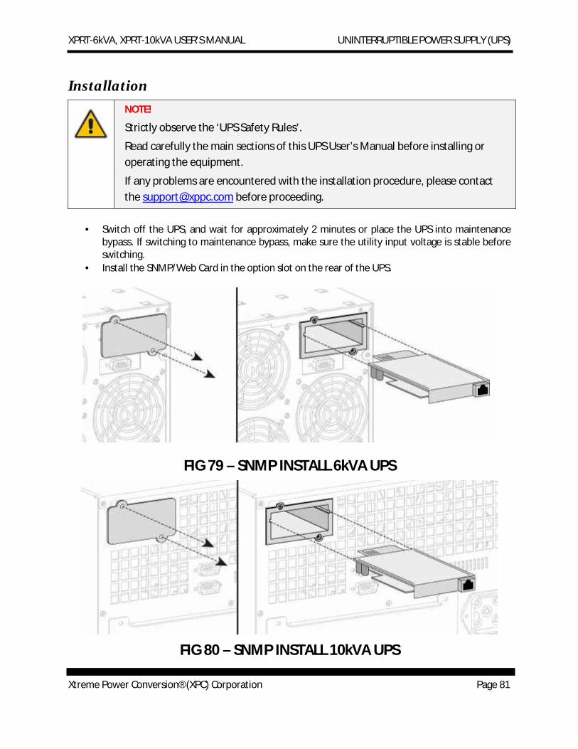
XPRT-6kVA, XPRT-10kVA USER’S MANUAL UNINTERRUPTIBLE POWER SUPPLY (UPS)
Xtreme Power Conversion® (XPC) Corporation Page 81
Installation NOTE!
Strictly observe the ‘UPS Safety Rules’.
Read carefully the main sections of this UPS User’s Manual before installing or operating the equipment.
If any problems are encountered with the installation procedure, please contact the [email protected] before proceeding.
· Switch off the UPS, and wait for approximately 2 minutes or place the UPS into maintenance bypass. If switching to maintenance bypass, make sure the utility input voltage is stable before switching.
· Install the SNMP/Web Card in the option slot on the rear of the UPS.
FIG 79 – SNMP INSTALL 6kVA UPS
FIG 80 – SNMP INSTALL 10kVA UPS
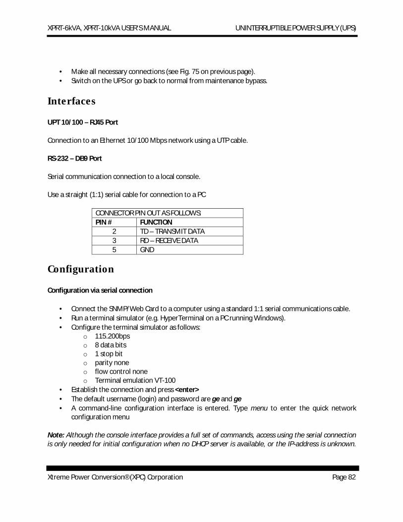
XPRT-6kVA, XPRT-10kVA USER’S MANUAL UNINTERRUPTIBLE POWER SUPPLY (UPS)
Xtreme Power Conversion® (XPC) Corporation Page 82
· Make all necessary connections (see Fig. 75 on previous page). · Switch on the UPS or go back to normal from maintenance bypass.
Interfaces
UPT 10/100 – RJ45 Port
Connection to an Ethernet 10/100 Mbps network using a UTP cable.
RS-232 – DB9 Port
Serial communication connection to a local console.
Use a straight (1:1) serial cable for connection to a PC
CONNECTOR PIN OUT AS FOLLOWS: PIN # FUNCTION
2 TD – TRANSMIT DATA 3 RD – RECEIVE DATA 5 GND
Configuration
Configuration via serial connection
· Connect the SNMP/Web Card to a computer using a standard 1:1 serial communications cable. · Run a terminal simulator (e.g. HyperTerminal on a PC running Windows). · Configure the terminal simulator as follows:
o 115.200bps o 8 data bits o 1 stop bit o parity none o flow control none o Terminal emulation VT-100
· Establish the connection and press <enter> · The default username (login) and password are ge and ge · A command-line configuration interface is entered. Type menu to enter the quick network
configuration menu
Note: Although the console interface provides a full set of commands, access using the serial connection is only needed for initial configuration when no DHCP server is available, or the IP-address is unknown.
XPRT-6kVA, XPRT-10kVA USER’S MANUAL UNINTERRUPTIBLE POWER SUPPLY (UPS)
Xtreme Power Conversion® (XPC) Corporation Page 83
The quick network configuration menu provides a simple interface for basic network configuration. For all other settings the user-friendly web interface is recommended.
Note: Saving the settings
Apart from some network parameters, most settings are immediately active. However, the card will revert to the last saved settings at reboot. Therefore, in order to permanently modify the SNMP/Web Card settings, remember to save the configuration after every change. This can be done by:
· Pressing S on the quick configuration menu · Entering nvsave at the command interface prompt
Configuration via the network
TELNET
· Launch a telnet client (e.g. on a PC running Windows, select Run from the Start menu and type telnet <IP>)
· The default username (login) and password are ge and ge · A command-line configuration interface is entered
WEB BROWSER
· Launch a web browser · Enter the URL of the SNMP/Web Card : http://<IP>/ · The default username and password are ge and ge
Note: Saving the settings
Apart from some network parameters, most settings are immediately active. However, the card will revert to the last saved settings at reboot. Therefore, in order to permanently modify the SNMP/Web Card settings, remember to save the configuration after every change.
Network Parameters
The SNMP/Web Card connects to the network using the following parameters:
IP ADDRESS IDENTIFIES THE CARD ON THE NETWORK SUBNET MASK DEFINES A RANGE OF ADDRESSES WITHIN THE ORANIZATION GATEWAY THE NODE USED FOR CONNECTION TO ADDRESSES OUSIDE THE
SUBNET

XPRT-6kVA, XPRT-10kVA USER’S MANUAL UNINTERRUPTIBLE POWER SUPPLY (UPS)
Xtreme Power Conversion® (XPC) Corporation Page 84
The card can be configured to obtain these settings automatically using DHCP or BOOTP protocols, or to use static addresses (manual configuration).
XPRT-6kVA, XPRT-10kVA USER’S MANUAL UNINTERRUPTIBLE POWER SUPPLY (UPS)
Xtreme Power Conversion® (XPC) Corporation Page 85
Default Configuration
The SNMP/Web Card comes with a pre-configured MAC address, with the following format:
00:12:93:fx:xx:xx 00:12:93 identifies the manufacturer
x:xx:xx is a unique code for every card
The MAC address is written on a label sticker on the SNMP/Web Card.
The factory default configuration for the SNMP/Web Card is using DHCP. Assign the UP address to the card MAC address in your DHCP server. Then reboot the card in order to have it retrieve the IP address. The card is now accessible and configurable over the network.
Reboot
Every time the network settings are changed, these become effective only after a reboot. The card can be rebooted by:
· Manually pressing the reset button on the front of the card · Using the console interface (either serial connection or telnet) by injecting the reboot command · Using a web browser, selecting Reboot in the menu
Access
WEB INTERFACE
After the installation and configuration of the SNMP/Web Card, the connection can be tested with a web browser.
· Launch the browser · Enter the URL of the SNMP/Web Card: http://<IP>/ (e.g. http://192.168.24.14/) · When prompted, enter username and password · The SNMP/Web Card home page will be shown
TROUBLESHOOTING
If no answer is received for the card, verify the card installation, cabling, and network configuration. Check the Ethernet connection to the card by launching a ping command from a workstation in the same subnet.
· Select Run from the Start menu · Enter ping <IP> (e.g. ping 192.168.24.14) · Verify that the SNMP Card is correctly replying

XPRT-6kVA, XPRT-10kVA USER’S MANUAL UNINTERRUPTIBLE POWER SUPPLY (UPS)
Xtreme Power Conversion® (XPC) Corporation Page 86


![Rack Tower Series (XPRT) · 2012. 5. 3. · XPRT‐1000, XPRT‐1500, XPRT‐2000, XPRT‐3000 USER’S MANUALUNINTERRUPTIBLE POWER SUPPLY (UPS) [3] EMC Statements ‐ FCC Part 15](https://img.pdfslide.us/doc/110x75/5ff10b5104360202d46c86c6/rack-tower-series-xprt-2012-5-3-xprta1000-xprta1500-xprta2000-xprta3000.jpg)
![Rack Tower Series (XPRT)XPRT‐1000, XPRT‐1500, XPRT‐2000, XPRT‐3000 USER’S MANUALUNINTERRUPTIBLE POWER SUPPLY (UPS) [3] EMC Statements ‐ FCC Part 15 Notice: Pursuant to](https://img.pdfslide.us/doc/110x75/606903521fa95911cb0070cd/rack-tower-series-xprt-xprta1000-xprta1500-xprta2000-xprta3000-useras.jpg)