Embed Size (px)
Citation preview
XS/SC26-2 Safety Controller Quick Start Guide
Origianl Document174869 Rev. D 5 January 2017
About this GuideThis guide is designed to help you create a sample confi guration for the XS/SC26-2 Safety Controller using the XS26-2 Expandable Safety Controller PC Interface. For complete information on mounting, device installation and operation, commissioning checkout procedures, product specifi cations, troubleshooting, and glossary, please refer to the Safety Controller Instruction Manual (p/n 174868) and support documentation for individual safety input and output devices. Use of this document assumes familiarity with pertinent safety standards and practices as outlined in the Instruction Manual.
Product Overview
2 www.bannerengineering.com - Tel: +1-763-544-3164 P/N 148770 Rev. F
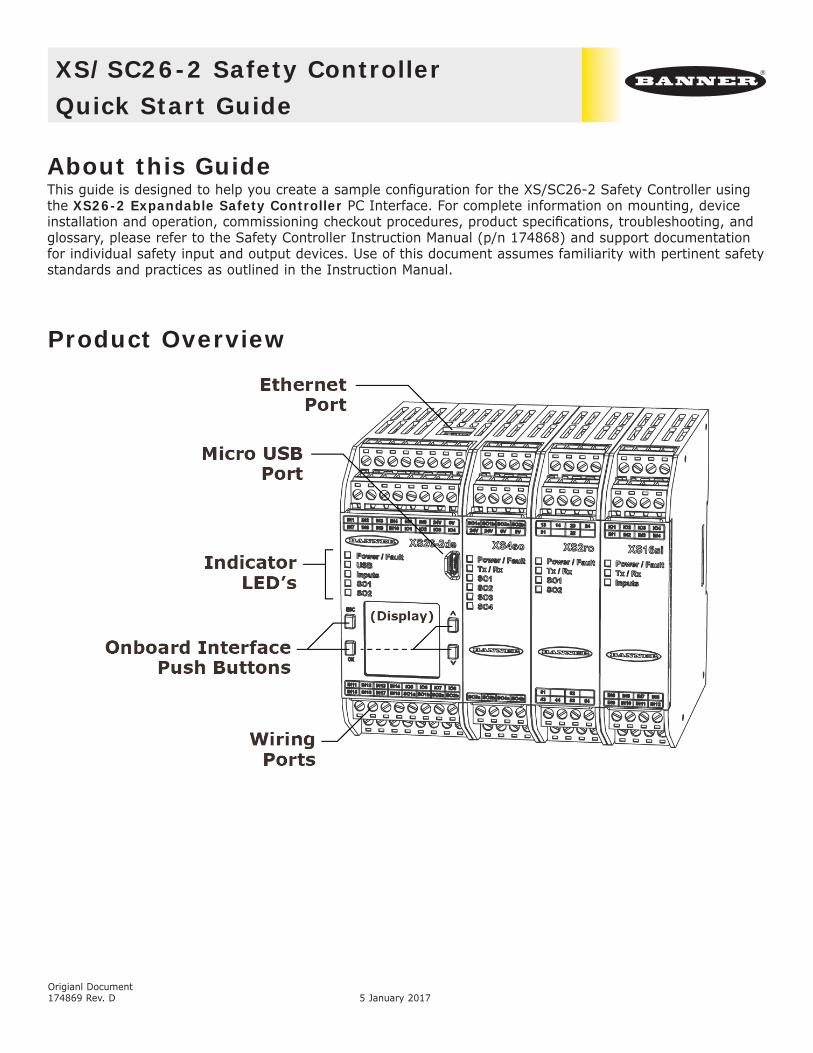
Designing a Sample Confi gurationThe confi guration process used in this guide provides basic understanding of the software features that are necessary to create a confi guration for any application. The example confi guration is based on a sample application which makes use of the following devices: an XS/SC26-2 Safety Controller, an E-stop button, a Safety Light Curtain, an Interlocked Gate Switch, and a Manual Reset. The illustration below depicts these devices and additional safety equipment for a sample Robotic Cell application.
3www.bannerengineering.com - Tel: +1-763-544-3164P/N 148770 Rev. F
Software Installation
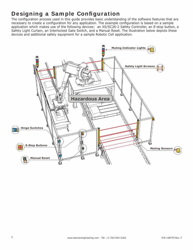
System Requirements
Operating system: Microsoft Windows XP Service Pack 3, Windows Vista, Windows 7, Windows 8 (except Windows RT), or Windows 10
System Type: 32-bit, 64-bit
Hard drive space: 80 MB (plus up to 280 MB for Microsoft .NET 4.0, if not already installed)
Memory (RAM): 512 MB minimum, 1 GB+ recommended
Processor: 1 GHz minimum, 2 GHz+ recommended
Screen Resolution: 1024x768 full color minimum, 1650x1050 full color recommended
Third-party software: Microsoft .NET 4.0 (included with installer), PDF Viewer (such as AdobeAcrobat)
USB port: USB 2.0
The XS26-2 Expandable Safety Controller PC Interface can be downloaded fromwww.bannerengineering.com/xs26.
Important: Administrative rights are required to install the Safety Controller drivers (needed for communication with the controller).
To install the software from the Banner Engineering website:1. Download the latest version of the software from www.bannerengineering.com/xs26.2. Navigate to and open the downloaded fi le.3. Click Next to begin the installation process.4. Confi rm the software destination and availability for users and click Next.5. Click Next to install the software.6. Depending on your system settings, a popup window may appear prompting to allow XS26-2 Expandable
Safety Controller to make changes to your computer. Click Yes.7. Click Close to exit the installer.
Open XS26-2 Expandable Safety Controller from the Desktop or the Start Menu.
1. Windows is a registered trademark of Microsoft Corporation in the United States and/or other countries.
4 www.bannerengineering.com - Tel: +1-763-544-3164 P/N 148770 Rev. F
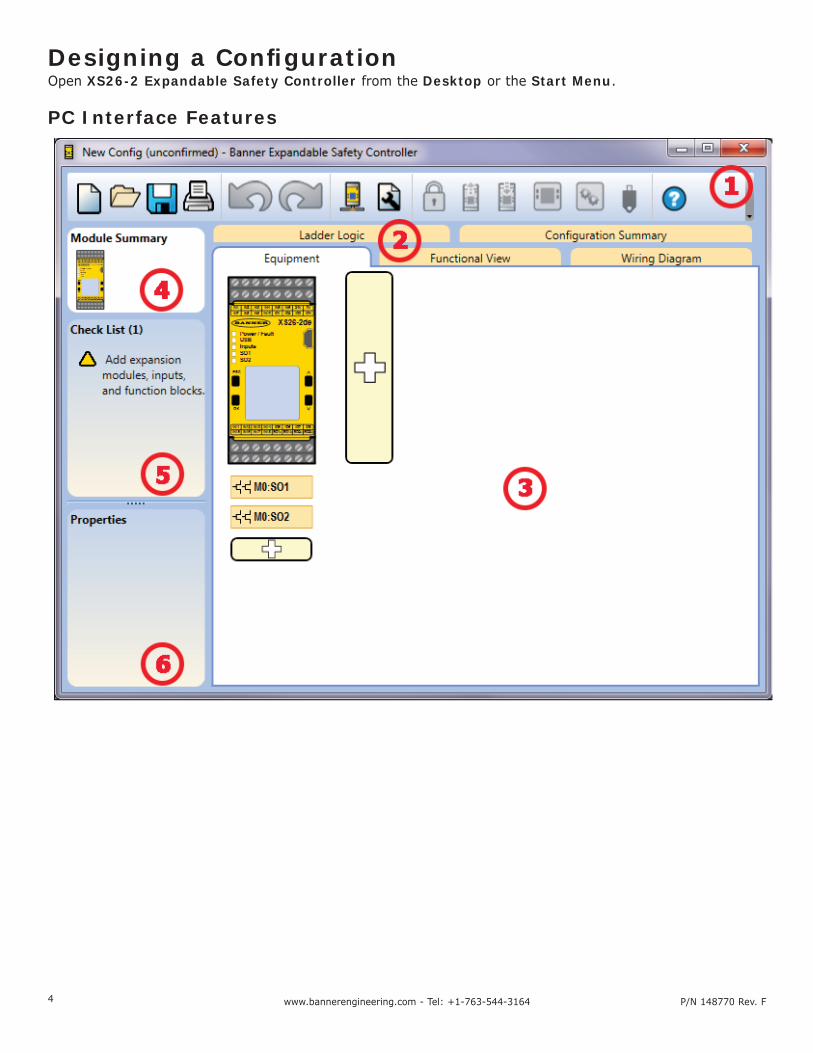
Designing a Confi gurationOpen XS26-2 Expandable Safety Controller from the Desktop or the Start Menu.
PC Interface Features
5www.bannerengineering.com - Tel: +1-763-544-3164P/N 148770 Rev. F
1 Navigation ToolbarStarts a New Project or opens a Recent project and Sample Confi gurations Displays Password Manager
Opens an existing projectReads data, such as Fault Log, Confi guration, Network Settings, and Device Information, from the Safety Controller
Saves (or Saves As) the project to the user-defi ned location
Writes the data, such as Confi guration and/or Network Settings, to the Safety Controller
Prints a customizable Confi guration Summary Makes the Live Mode view available
Reverts up to ten previous actions Makes the Simulation Mode View available
Re-applies up to ten previously reverted actions Indicates SC-XM2 drive connection
Displays Network Settings Opens the Help options
Displays Project Settings
2 Tabs• Equipment—displays an editable view of all connected equipment.• Functional View—provides an editable iconic representation of the control logic.• Wiring Diagram—displays the I/O device wiring detail for use by the installer.• Ladder Logic—displays a symbolic representation of the Controller’s safeguarding logic for the use by
the machine designer or controls engineer.• Industrial Ethernet (when enabled)—displays editable network confi guration options.• Confi guration Summary—displays a detailed confi guration summary.• Live Mode (when enabled)—displays the live mode data, including current faults.• Simulation Mode (when enabled)—displays the simulation mode data
3 Selected viewDisplays the view corresponding to the selected tab (Equipment view shown).
4 Module SummaryDisplays the Base Controller and any connected modules.
5 ChecklistProvides action items to confi gure the system and correct any errors to successfully complete the confi guration.
6 PropertiesDisplays the properties of the selected device, function block, or connection (properties cannot be edited in this view, click Edit to make changes).
6 www.bannerengineering.com - Tel: +1-763-544-3164 P/N 148770 Rev. F
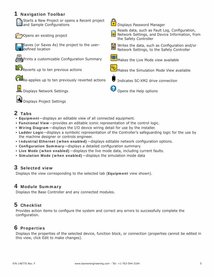
Defi ne the Project SettingsClick Project Settings.
Enter the information about the project:
Confi guration NameName of the confi guration; displayed on the controller (models with display); diff erent from fi le name.
ProjectProject name is useful for distinguishing between various application areas.
AuthorPerson designing the confi guration.
NotesSupplemental information for this confi guration or project.
Project DateDate pertaining to the project.
Add Equipment1. On the Equipment view select your
Base Module properties (Display, Industrial Ethernet, Expandability) by either double-clicking the module or clicking the Edit under the properties table when the module is selected.
2. Add Safety Input devices by clicking under the Base Module:
• Emergency Stop• Gate Switch• Optical Sensor
Note: For the purpose of this confi guration default device properties are used.
7www.bannerengineering.com - Tel: +1-763-544-3164P/N 148770 Rev. F
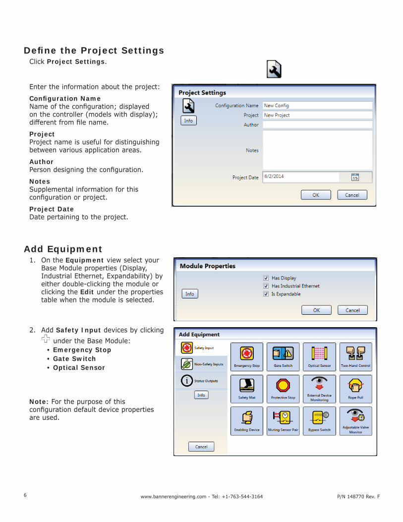
3. Add Non-Safety Inputs by clicking under the Base Module:
• Manual Reset
Create Connections4. Go to Functional View.
Note: The Check List on the left lists any missing connections that need to be added before the confi guration is valid.
5. Add the Function Blocks by clicking on one of the empty placeholders in the middle area:
• Latch Reset Block

8 www.bannerengineering.com - Tel: +1-763-544-3164 P/N 148770 Rev. F
6. Add Logic Blocks by clicking on one of the empty placeholders in the middle area:
• And
7. For this confi guration, increase the number of Input Nodes to “3”.
8. Connect Optical Sensor, Gate Switch, and Latch Reset Block to one of the input nodes on the AND block.
9. Connect Emergency Stop and Manual Reset to the Latch Reset Block.
10. Connect the AND block to the Solid State Output (SO1).
Note: You may re-arrange any of the Equipment blocks or Functional Elements blocks for a better visual representation of the connections. Solid State Output blocks cannot be moved.
© Banner Engineering Corp. All rights reserved.
Banner Engineering Corp Limited WarrantyBanner Engineering Corp. warrants its products to be free from defects in material and workmanship for one year following the date of shipment. Banner Engineering Corp. will repair or replace, free of charge, any product of its manufacture which, at the time it is returned to the factory, is found to have been defective during the warranty period. This warranty does not cover damage or liability for misuse, abuse, or the improper application or installation of the Banner product.THIS LIMITED WARRANTY IS EXCLUSIVE AND IN LIEU OF ALL OTHER WARRANTIES WHETHER EXPRESS OR IMPLIED (INCLUDING, WITHOUT LIMITATION, ANY WARRANTY OF MERCHANTABILITY OR FITNESS FOR A PARTICULAR PURPOSE), AND WHETHER ARISING UNDER COURSE OF PERFORMANCE, COURSE OF DEALING OR TRADE USAGE.This Warranty is exclusive and limited to repair or, at the discretion of Banner Engineering Corp., replacement. IN NO EVENT SHALL BANNER ENGINEERING CORP. BE LIABLE TO BUYER OR ANY OTHER PERSON OR ENTITY FOR ANY EXTRA COSTS, EXPENSES, LOSSES, LOSS OF PROFITS, OR ANY INCIDENTAL, CONSEQUENTIAL OR SPECIAL DAMAGES RESULTING FROM ANY PRODUCT DEFECT OR FROM THE USE OR INABILITY TO USE THE PRODUCT, WHETHER ARISING IN CONTRACT OR WARRANTY, STATUTE, TORT, STRICT LIABILITY, NEGLIGENCE, OR OTHERWISE.Banner Engineering Corp. reserves the right to change, modify or improve the design of the product without assuming any obligations or liabilities relating to any product previously manufactured by Banner Engineering Corp. Any misuse, abuse, or improper application or installation of this product or use of the product for personal protection applications when the product is identifi ed as not intended for such purposes will void the product warranty. Any modifi cations to this product without prior express approval by Banner Engineering Corp will void the product warranties. All specifi cations published in this document are subject to change; Banner reserves the right to modify product specifi cations or update documentation at any time. Specifi cations and product information in English supersedes that which is provided in any other language. For the most recent version of any documentation, refer to: www.bannerengineering.com.
Save the Confi guration1. Click Save.2. Select Save As.3. Navigate to the folder where you wish to save your confi guration.4. Name the fi le (may be the same or diff erent from the
Confi guration name).5. Click Save.
Confi rm the Confi guration1. Power the Safety Controller and connect it to the PC using the
appropriate USB cable.2. Click Send to Controller.3. Enter the password (the default password is 1901).4. Click Continue to enter the confi g-mode.5. After the Reading Confi guration from the Controller process is
completed, the Confi rm Confi guration screen opens. Verify that the confi guration is correct.
6. Scroll to the end of the confi guration and click Confi rm.7. After the Send Confi guration To Controller process has
completed, click Close.8. Reset the Safety Controller for the changes to take eff ect.
You have completed the sample confi guration.
It is the responsibility of the Qualifi ed Person who confi gures, installs, or maintains the XS26-2 Safety Controller to:
• Carefully read, understand, and follow the information in the XS26-2 manual (which can be accessed via the drop-down Help menu of the PC Interface)
• Perform a risk assessment of the specifi c machine guarding application• Determine what safeguarding devices and methods are appropriate per the requirements
defi ned in ISO 13849-1 and those referenced in the XS26-2 manual• Create and confi rm each XS26-2 confi guration and then verify that the entire safeguarding
system (including input devices and output devices) is operational and working as intended• Periodically re-verify, as needed, that the entire safeguarding system is working as intended
Failure to follow any of these recommendations may potentially create a dangerous condition that may lead to serious injury or death.

![Data Structures UW CSE 190p Summer 2012. >>> xs = range(3) >>> xs = [1,2,3] >>> xs = [‘a’,’b’,’c’] >>> xs = [1, ‘a’, 3] >>> xs = [[1,2,3], [‘a’,’b’,’c’]]](https://img.pdfslide.us/doc/110x75/56649d925503460f94a78dee/data-structures-uw-cse-190p-summer-2012-xs-range3-xs-123.jpg)


![S90 XS/S70 XS Editor VST Owner's Manual - Yamaha · Starting the S90 XS/S70 XS Editor VST S90 XS/S70 XS Editor VST Owner’s Manual 6 13. In Quick Set Up, select [1] or [2]. nFor](https://img.pdfslide.us/doc/110x75/5fa5d7be5c20e054d9711161/s90-xss70-xs-editor-vst-owners-manual-yamaha-starting-the-s90-xss70-xs-editor.jpg)


![FEBRUARY 2017 7069 - bioMérieux...5yiwxmsrw vipexih xs svhivw erh mrzsmgiw evi qerekih f] xli 7epiw %hqmrmwxvexmsr 8ieq 3yv xipitlsri pmriw evi stir 1srhe] xs *vmhe] xs erh xs 'irxvep](https://img.pdfslide.us/doc/110x75/60ca5b81d56549593b316ac0/february-2017-7069-biomrieux-5yiwxmsrw-vipexih-xs-svhivw-erh-mrzsmgiw-evi.jpg)