Embed Size (px)
Citation preview
Rev: 3.1 1
Xrev Transmit Help Files
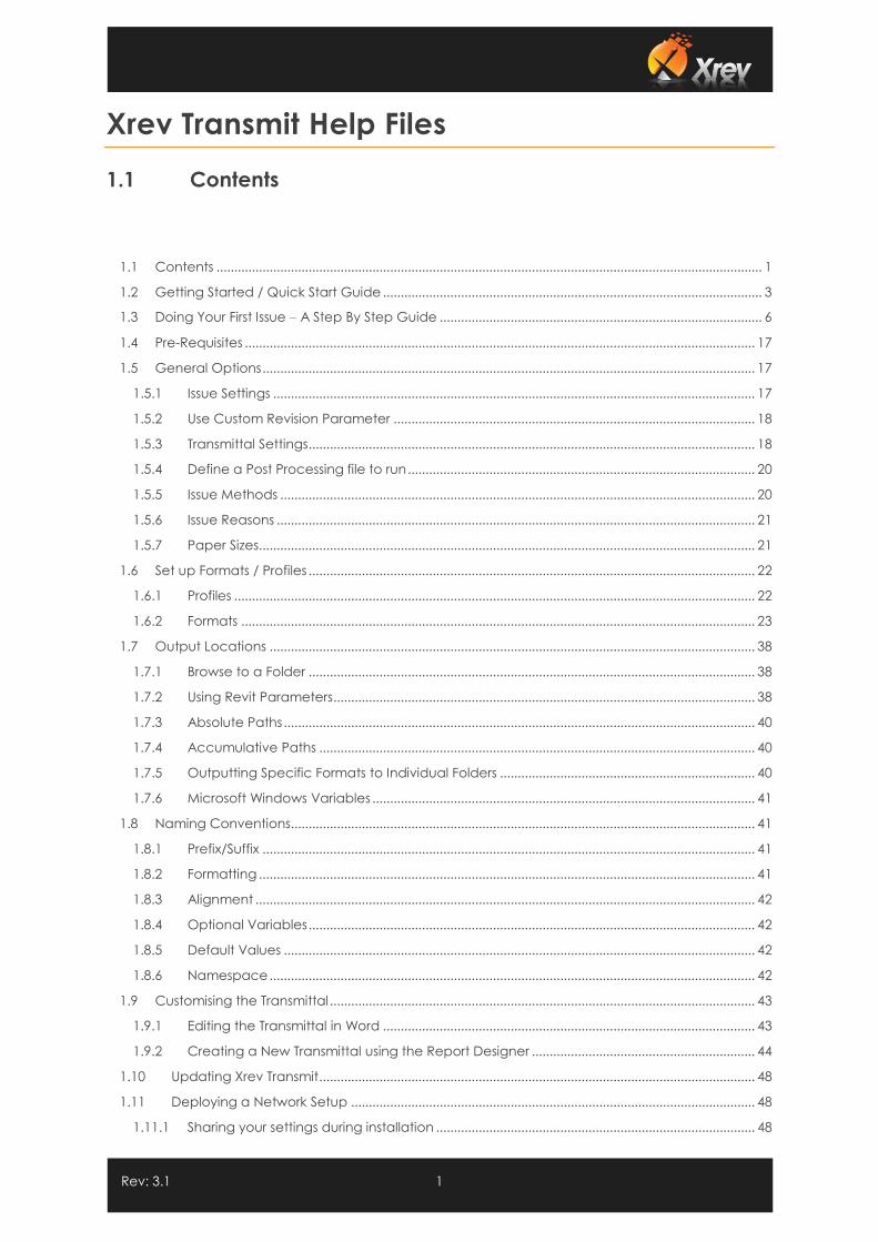
1.1 Contents
1.1 Contents .......................................................................................................................................................... 1
1.2 Getting Started / Quick Start Guide ........................................................................................................... 3
1.3 Doing Your First Issue – A Step By Step Guide ........................................................................................... 6
1.4 Pre-Requisites ................................................................................................................................................ 17
1.5 General Options ........................................................................................................................................... 17
1.5.1 Issue Settings ........................................................................................................................................ 17
1.5.2 Use Custom Revision Parameter ...................................................................................................... 18
1.5.3 Transmittal Settings .............................................................................................................................. 18
1.5.4 Define a Post Processing file to run .................................................................................................. 20
1.5.5 Issue Methods ...................................................................................................................................... 20
1.5.6 Issue Reasons ....................................................................................................................................... 21
1.5.7 Paper Sizes ............................................................................................................................................ 21
1.6 Set up Formats / Profiles .............................................................................................................................. 22
1.6.1 Profiles ................................................................................................................................................... 22
1.6.2 Formats ................................................................................................................................................. 23
1.7 Output Locations ......................................................................................................................................... 38
1.7.1 Browse to a Folder .............................................................................................................................. 38
1.7.2 Using Revit Parameters....................................................................................................................... 38
1.7.3 Absolute Paths ..................................................................................................................................... 40
1.7.4 Accumulative Paths ........................................................................................................................... 40
1.7.5 Outputting Specific Formats to Individual Folders ........................................................................ 40
1.7.6 Microsoft Windows Variables ............................................................................................................ 41
1.8 Naming Conventions................................................................................................................................... 41
1.8.1 Prefix/Suffix ........................................................................................................................................... 41
1.8.2 Formatting ............................................................................................................................................ 41
1.8.3 Alignment ............................................................................................................................................. 42
1.8.4 Optional Variables .............................................................................................................................. 42
1.8.5 Default Values ..................................................................................................................................... 42
1.8.6 Namespace ......................................................................................................................................... 42
1.9 Customising the Transmittal ........................................................................................................................ 43
1.9.1 Editing the Transmittal in Word ......................................................................................................... 43
1.9.2 Creating a New Transmittal using the Report Designer ............................................................... 44
1.10 Updating Xrev Transmit ........................................................................................................................... 48
1.11 Deploying a Network Setup .................................................................................................................. 48
1.11.1 Sharing your settings during installation .......................................................................................... 48
Rev: 3.1 2
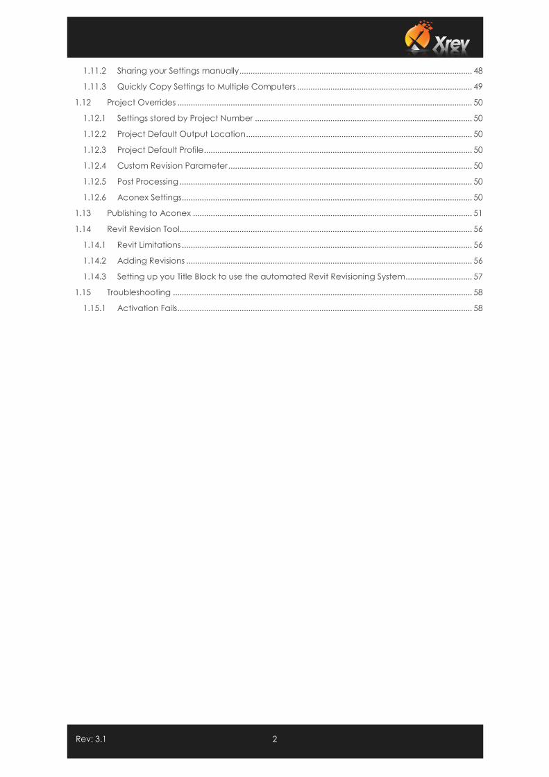
1.11.2 Sharing your Settings manually ......................................................................................................... 48
1.11.3 Quickly Copy Settings to Multiple Computers ............................................................................... 49
1.12 Project Overrides ..................................................................................................................................... 50
1.12.1 Settings stored by Project Number .................................................................................................. 50
1.12.2 Project Default Output Location ...................................................................................................... 50
1.12.3 Project Default Profile ......................................................................................................................... 50
1.12.4 Custom Revision Parameter .............................................................................................................. 50
1.12.5 Post Processing .................................................................................................................................... 50
1.12.6 Aconex Settings................................................................................................................................... 50
1.13 Publishing to Aconex .............................................................................................................................. 51
1.14 Revit Revision Tool.................................................................................................................................... 56
1.14.1 Revit Limitations ................................................................................................................................... 56
1.14.2 Adding Revisions ................................................................................................................................. 56
1.14.3 Setting up you Title Block to use the automated Revit Revisioning System.............................. 57
1.15 Troubleshooting ....................................................................................................................................... 58
1.15.1 Activation Fails ..................................................................................................................................... 58
Rev: 3.1 3
1.2 Getting Started / Quick Start Guide
Below is a quick start guide to configuring Xrev Transmit for your first Sheet/Drawings Issue. There are
more advanced tasks you can complete with it which are outlined further in this document. But, the
below guide should give you enough information to install Xrev Transmit, setup and do an issue with
your required settings fairly quickly.
1. Download Xrev Transmit from www.xrev.com.au
2. Install the appropriate versions you require (2013, 2014, …). Note that you will require
Administrator privileges on your workstation to install and each version uses the same
"database" of settings.
3. Follow the prompts and install the sub-components if prompted. Xrev Transmit requires
BioPDF for automatic naming of PDF's (the PDF Printer Xrev Transmit uses) or an existing
installation of Adobe PDF, Bluebeam PDF or PDF Creator. If this is already installed the
installation takes no longer than a minute to complete on most workstations.
4. Xrev Transmit is now installed and ready to use.
5. Open the version of Revit you installed Xrev Transmit on, and open a project with a project
number entered. NOTE: Xrev Transmit will not be visible in the family environment; you must
have a project file open.
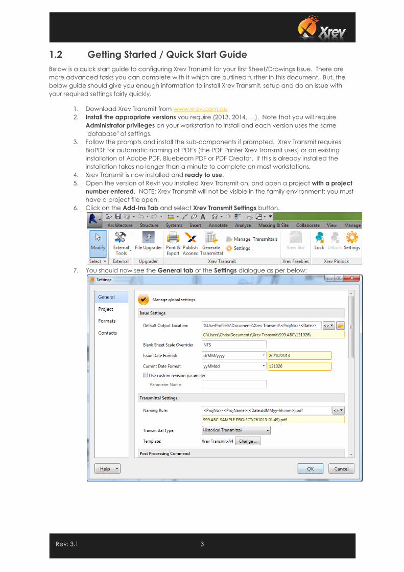
6. Click on the Add-Ins Tab and select Xrev Transmit Settings button.
7. You should now see the General tab of the Settings dialogue as per below:
Rev: 3.1 4
8. This tab is used to manage settings that will be used generally for all projects. The first item
to setup is the “Default Output Location”. This is the root directory of where you want files to
be output to when doing your sheet/drawing issues. By clicking the Browse button
you can navigate to the folder you wish the files to always go. However, you can be
clever about it! By clicking <> you can use parameter information from Revit and substitute
out folder names that match with Revit parameters. You can even have the formats
append to this output location to place different formats (DWG’s, PDF’s) into their own
folders. For further information review the Output Locations section.
9. Here is an example of a parametric output location (this way is doesn't matter what
project your work on, you never have to change this setting!):
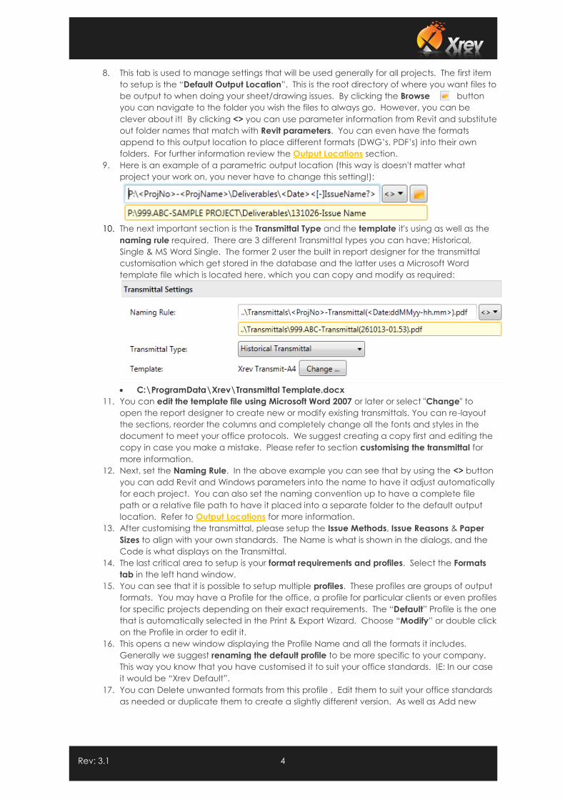
10. The next important section is the Transmittal Type and the template it's using as well as the
naming rule required. There are 3 different Transmittal types you can have; Historical,
Single & MS Word Single. The former 2 user the built in report designer for the transmittal
customisation which get stored in the database and the latter uses a Microsoft Word
template file which is located here, which you can copy and modify as required:
C:\ProgramData\Xrev\Transmittal Template.docx
11. You can edit the template file using Microsoft Word 2007 or later or select "Change" to
open the report designer to create new or modify existing transmittals. You can re-layout
the sections, reorder the columns and completely change all the fonts and styles in the
document to meet your office protocols. We suggest creating a copy first and editing the
copy in case you make a mistake. Please refer to section customising the transmittal for
more information.
12. Next, set the Naming Rule. In the above example you can see that by using the <> button
you can add Revit and Windows parameters into the name to have it adjust automatically
for each project. You can also set the naming convention up to have a complete file
path or a relative file path to have it placed into a separate folder to the default output
location. Refer to Output Locations for more information.
13. After customising the transmittal, please setup the Issue Methods, Issue Reasons & Paper
Sizes to align with your own standards. The Name is what is shown in the dialogs, and the
Code is what displays on the Transmittal.
14. The last critical area to setup is your format requirements and profiles. Select the Formats
tab in the left hand window.
15. You can see that it is possible to setup multiple profiles. These profiles are groups of output
formats. You may have a Profile for the office, a profile for particular clients or even profiles
for specific projects depending on their exact requirements. The “Default” Profile is the one
that is automatically selected in the Print & Export Wizard. Choose “Modify” or double click
on the Profile in order to edit it.
16. This opens a new window displaying the Profile Name and all the formats it includes.
Generally we suggest renaming the default profile to be more specific to your company.
This way you know that you have customised it to suit your office standards. IE: In our case
it would be “Xrev Default”.
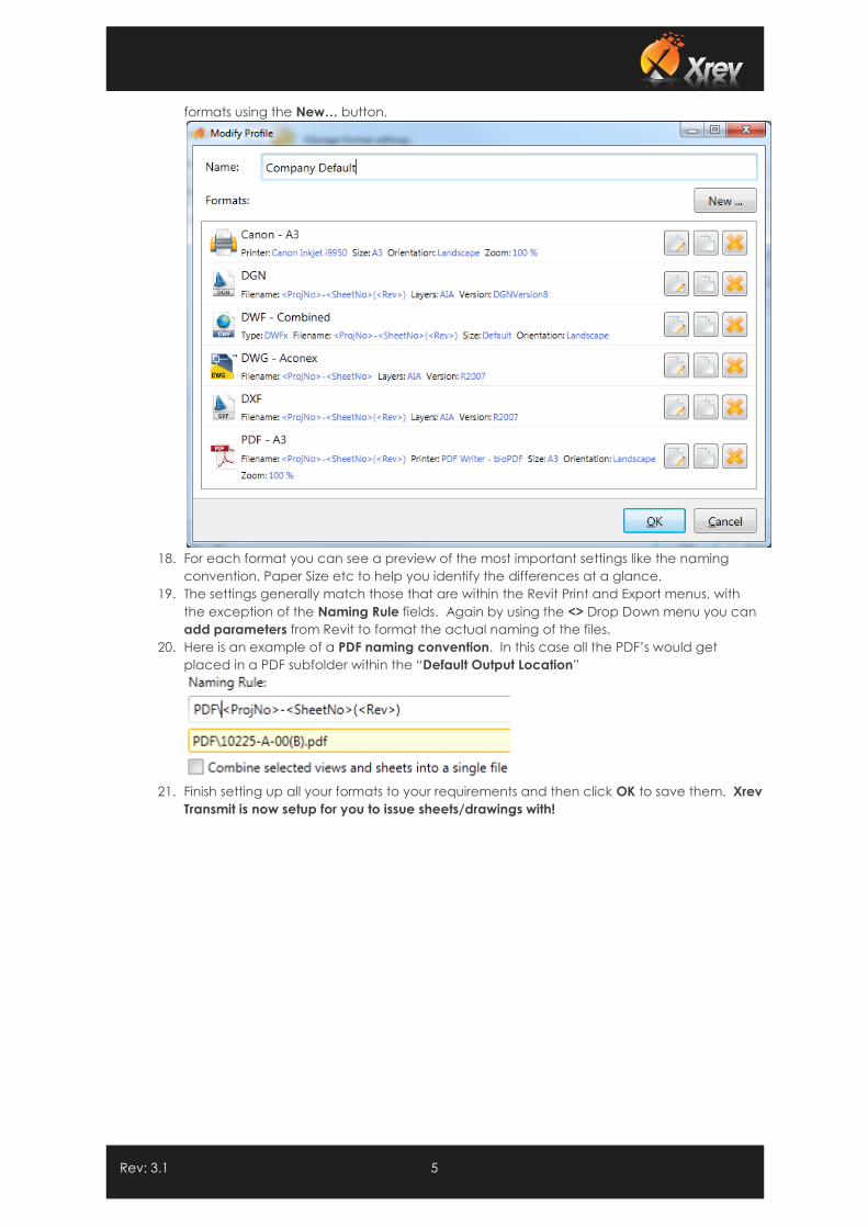
17. You can Delete unwanted formats from this profile , Edit them to suit your office standards
as needed or duplicate them to create a slightly different version. As well as Add new
Rev: 3.1 5
formats using the New… button.
18. For each format you can see a preview of the most important settings like the naming
convention, Paper Size etc to help you identify the differences at a glance.
19. The settings generally match those that are within the Revit Print and Export menus, with
the exception of the Naming Rule fields. Again by using the <> Drop Down menu you can
add parameters from Revit to format the actual naming of the files.
20. Here is an example of a PDF naming convention. In this case all the PDF’s would get
placed in a PDF subfolder within the “Default Output Location”
21. Finish setting up all your formats to your requirements and then click OK to save them. Xrev
Transmit is now setup for you to issue sheets/drawings with!
Rev: 3.1 6
1.3 Doing Your First Issue – A Step By Step Guide
Once you have configured the settings, all issues within Xrev Transmit are quick and easy. It’s just a
matter of following through the step by step wizard to have Xrev Transmit generate all the files you
want. You can then choose to Publish the files to Aconex or generate a Transmittal document to send
with the drawings.
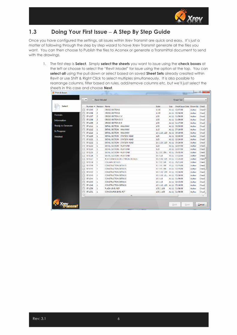
1. The first step is Select. Simply select the sheets you want to issue using the check boxes at
the left or choose to select the “Revit Model” for issue using the option at the top. You can
select all using the pull down or select based on saved Sheet Sets already created within
Revit or use Shift & Right Click to select multiples simultaneously. It is also possible to
rearrange columns, filter based on rules, add/remove columns etc, but we’ll just select the
sheets in this case and choose Next.
Rev: 3.1 7
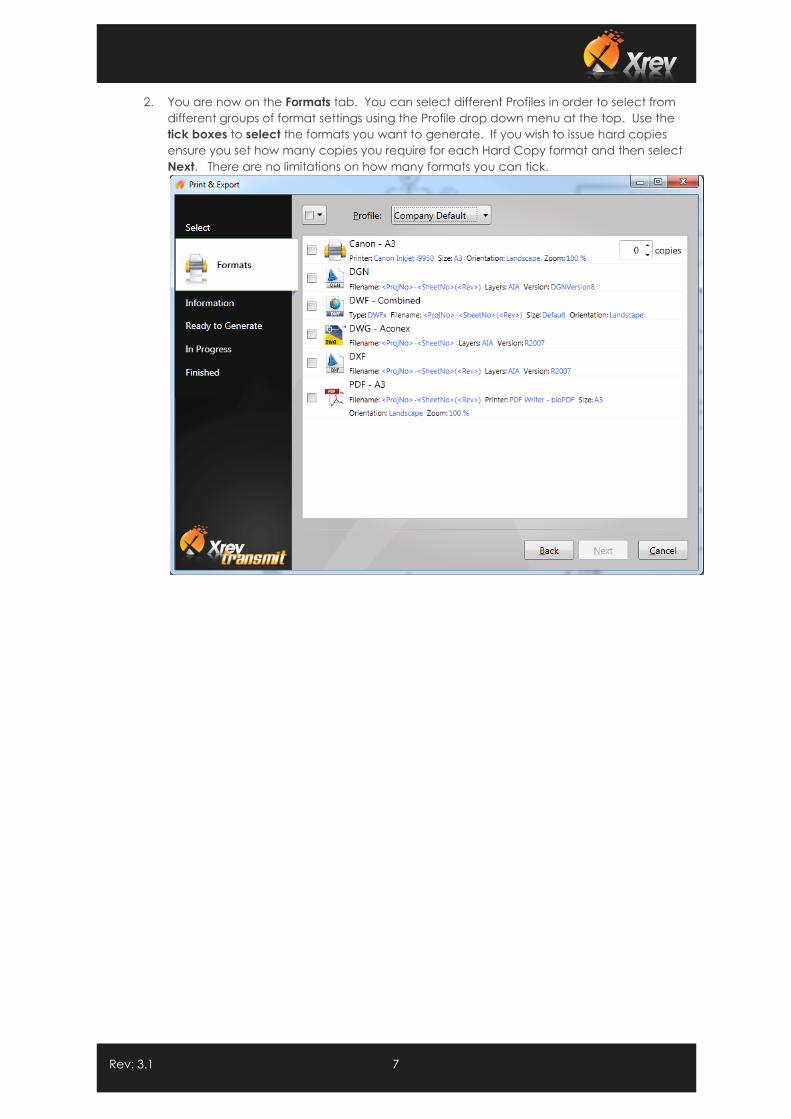
2. You are now on the Formats tab. You can select different Profiles in order to select from
different groups of format settings using the Profile drop down menu at the top. Use the
tick boxes to select the formats you want to generate. If you wish to issue hard copies
ensure you set how many copies you require for each Hard Copy format and then select
Next. There are no limitations on how many formats you can tick.
Rev: 3.1 8
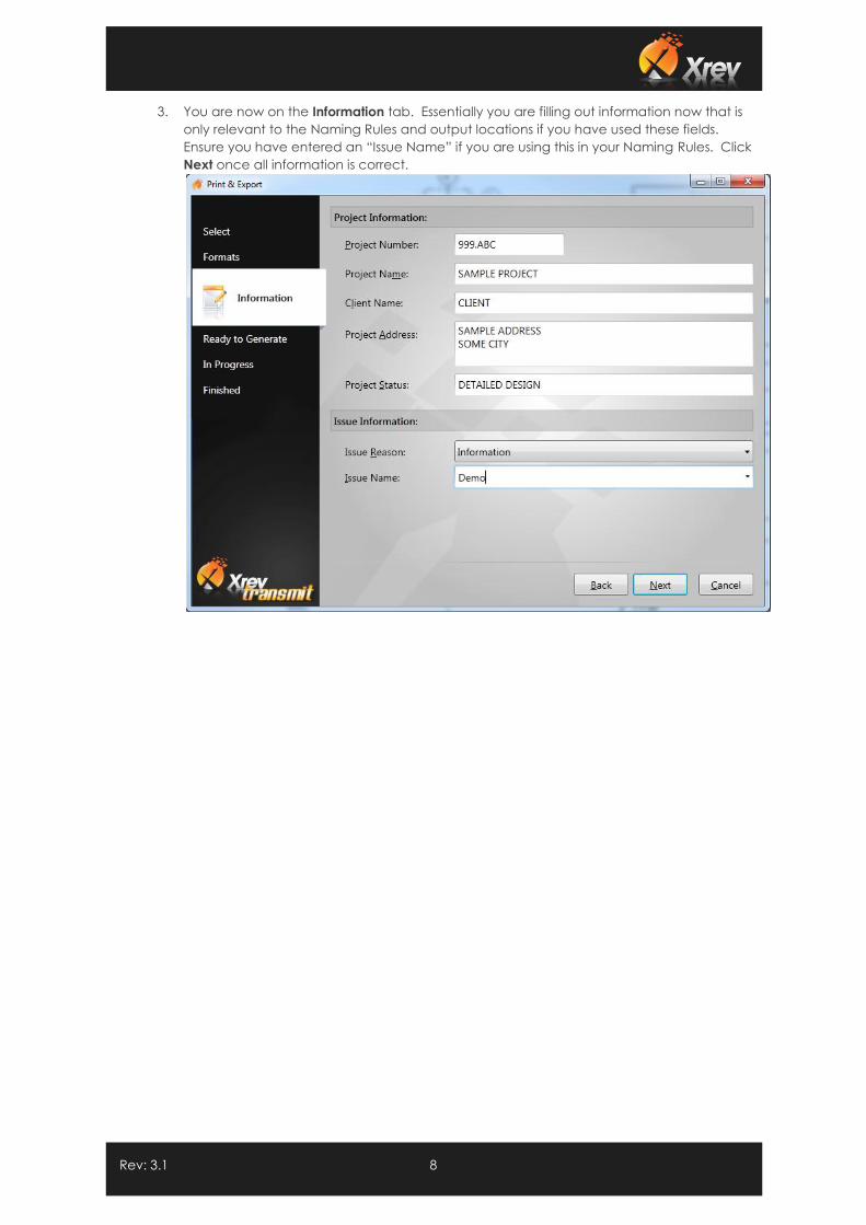
3. You are now on the Information tab. Essentially you are filling out information now that is
only relevant to the Naming Rules and output locations if you have used these fields.
Ensure you have entered an “Issue Name” if you are using this in your Naming Rules. Click
Next once all information is correct.
Rev: 3.1 9
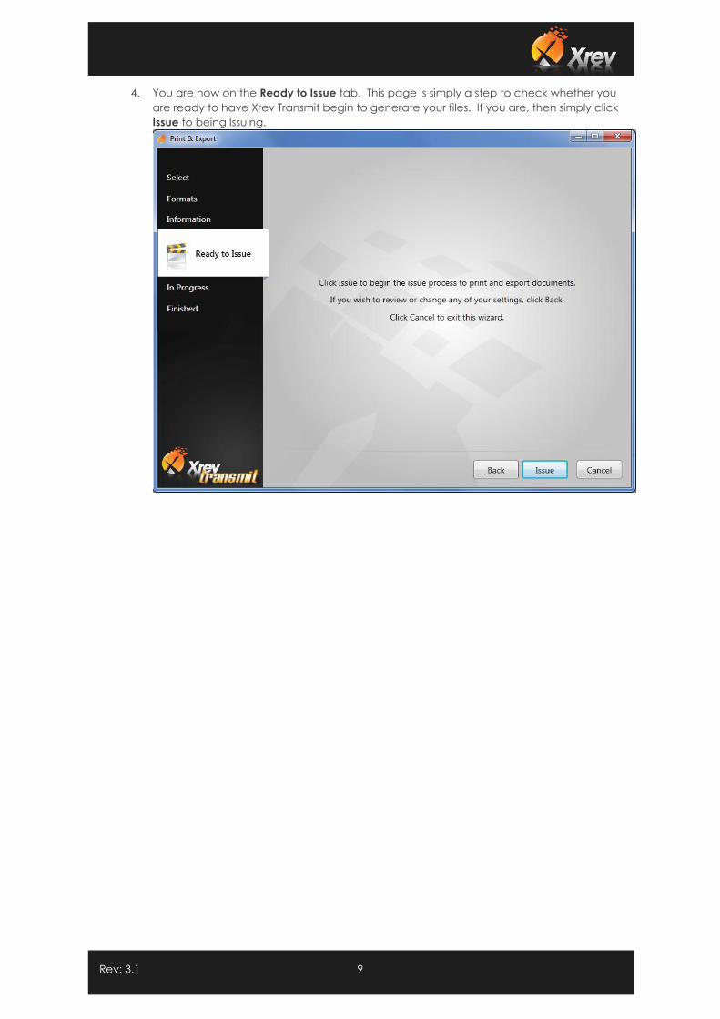
4. You are now on the Ready to Issue tab. This page is simply a step to check whether you
are ready to have Xrev Transmit begin to generate your files. If you are, then simply click
Issue to being Issuing.
Rev: 3.1 10
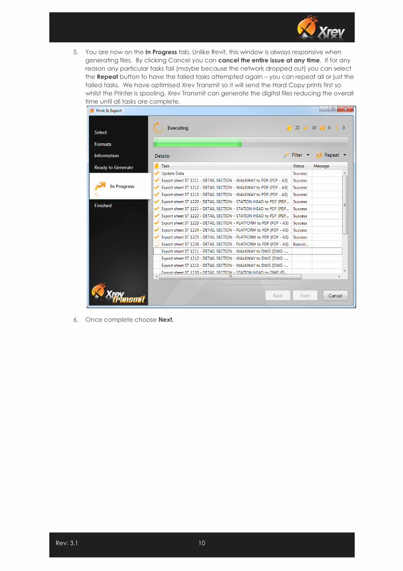
5. You are now on the In Progress tab. Unlike Revit, this window is always responsive when
generating files. By clicking Cancel you can cancel the entire issue at any time. If for any
reason any particular tasks fail (maybe because the network dropped out) you can select
the Repeat button to have the failed tasks attempted again – you can repeat all or just the
failed tasks. We have optimised Xrev Transmit so it will send the Hard Copy prints first so
whilst the Printer is spooling, Xrev Transmit can generate the digital files reducing the overall
time until all tasks are complete.
6. Once complete choose Next.
Rev: 3.1 11
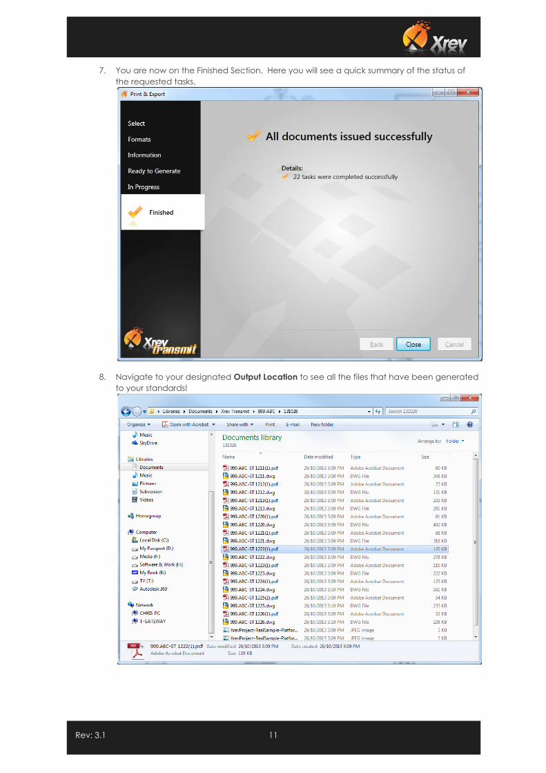
7. You are now on the Finished Section. Here you will see a quick summary of the status of
the requested tasks.
8. Navigate to your designated Output Location to see all the files that have been generated
to your standards!
Rev: 3.1 12
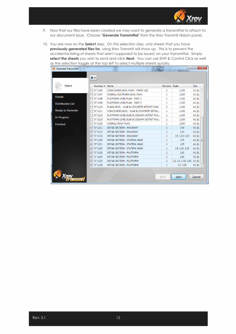
9. Now that our files have been created we may want to generate a transmittal to attach to
our document issue. Choose "Generate Transmittal" from the Xrev Transmit ribbon panel.
10. You are now on the Select step. On this selection step, only sheets that you have
previously generated files for, using Xrev Transmit will show up. This is to prevent the
accidental listing of sheets that aren't supposed to be issued, on your Transmittal. Simply
select the sheets you wish to send and click Next. You can use Shift & Control Click as well
as the selection toggle at the top left to select multiple sheets quickly.
Rev: 3.1 13
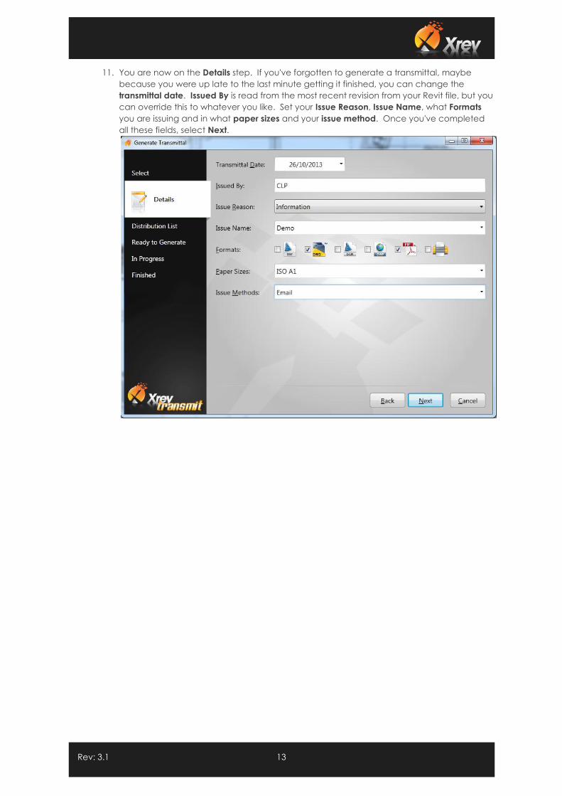
11. You are now on the Details step. If you've forgotten to generate a transmittal, maybe
because you were up late to the last minute getting it finished, you can change the
transmittal date. Issued By is read from the most recent revision from your Revit file, but you
can override this to whatever you like. Set your Issue Reason, Issue Name, what Formats
you are issuing and in what paper sizes and your issue method. Once you've completed
all these fields, select Next.
Rev: 3.1 14
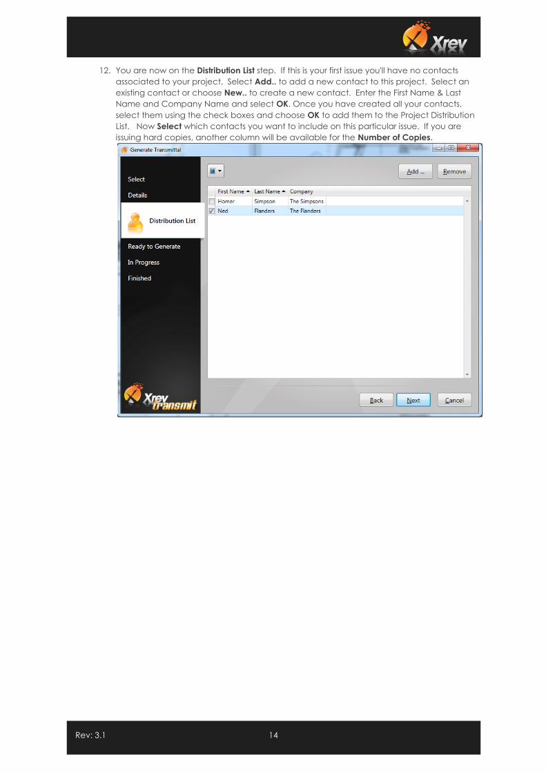
12. You are now on the Distribution List step. If this is your first issue you'll have no contacts
associated to your project. Select Add.. to add a new contact to this project. Select an
existing contact or choose New.. to create a new contact. Enter the First Name & Last
Name and Company Name and select OK. Once you have created all your contacts,
select them using the check boxes and choose OK to add them to the Project Distribution
List. Now Select which contacts you want to include on this particular issue. If you are
issuing hard copies, another column will be available for the Number of Copies.
Rev: 3.1 15
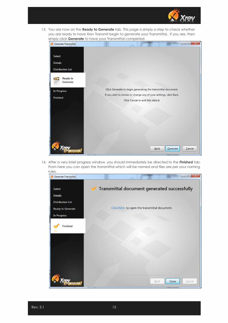
13. You are now on the Ready to Generate tab. This page is simply a step to check whether
you are ready to have Xrev Transmit begin to generate your Transmittal. If you are, then
simply click Generate to have your Transmittal completed.
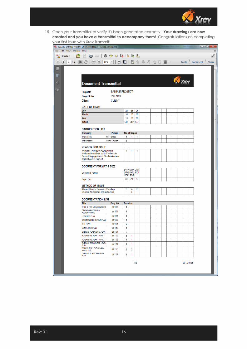
14. After a very brief progress window, you should immediately be directed to the Finished tab.
From here you can open the transmittal which will be named and files are per your naming
rules.
Rev: 3.1 16
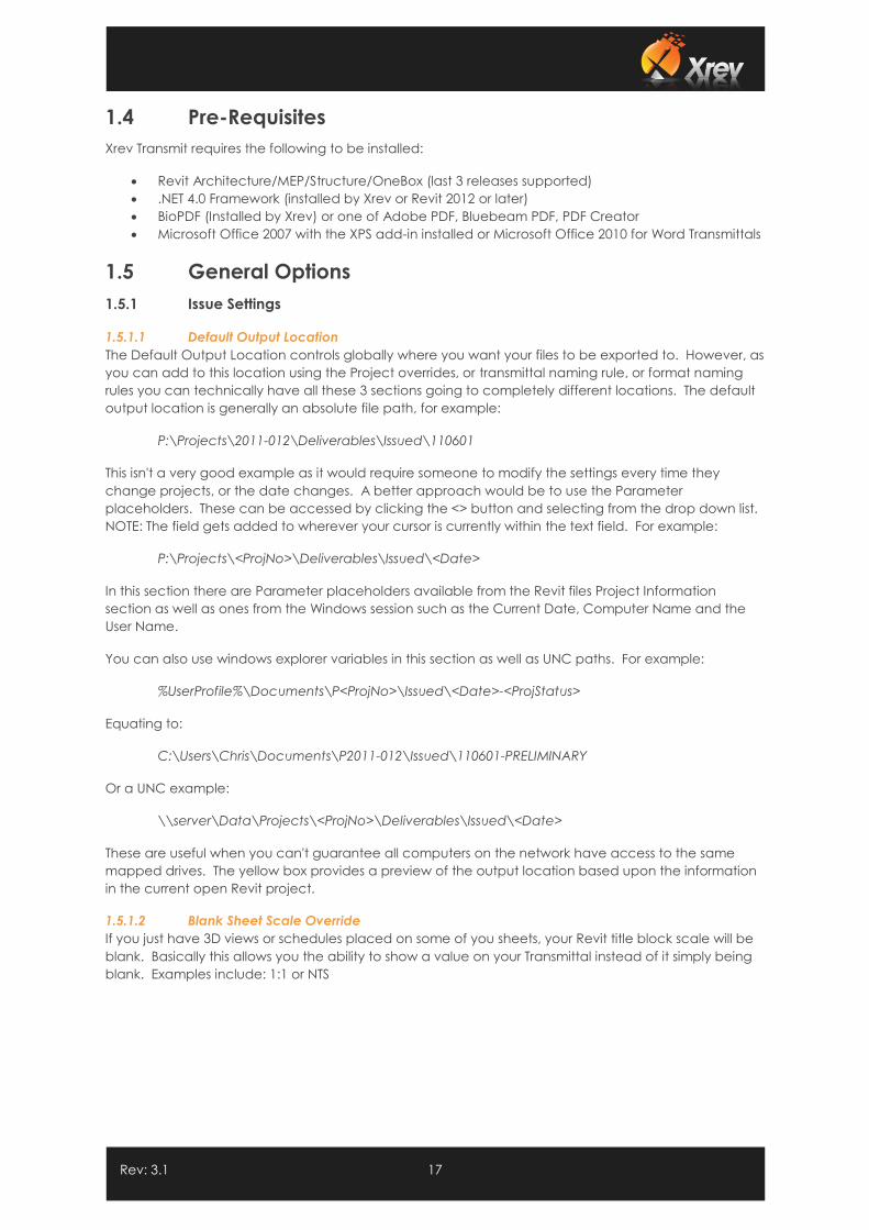
15. Open your transmittal to verify it's been generated correctly. Your drawings are now
created and you have a transmittal to accompany them! Congratulations on completing
your first issue with Xrev Transmit!
Rev: 3.1 17
1.4 Pre-Requisites
Xrev Transmit requires the following to be installed:
Revit Architecture/MEP/Structure/OneBox (last 3 releases supported)
.NET 4.0 Framework (installed by Xrev or Revit 2012 or later)
BioPDF (Installed by Xrev) or one of Adobe PDF, Bluebeam PDF, PDF Creator
Microsoft Office 2007 with the XPS add-in installed or Microsoft Office 2010 for Word Transmittals
1.5 General Options
1.5.1 Issue Settings
1.5.1.1 Default Output Location
The Default Output Location controls globally where you want your files to be exported to. However, as
you can add to this location using the Project overrides, or transmittal naming rule, or format naming
rules you can technically have all these 3 sections going to completely different locations. The default
output location is generally an absolute file path, for example:
P:\Projects\2011-012\Deliverables\Issued\110601
This isn't a very good example as it would require someone to modify the settings every time they
change projects, or the date changes. A better approach would be to use the Parameter
placeholders. These can be accessed by clicking the <> button and selecting from the drop down list.
NOTE: The field gets added to wherever your cursor is currently within the text field. For example:
P:\Projects\<ProjNo>\Deliverables\Issued\<Date>
In this section there are Parameter placeholders available from the Revit files Project Information
section as well as ones from the Windows session such as the Current Date, Computer Name and the
User Name.
You can also use windows explorer variables in this section as well as UNC paths. For example:
%UserProfile%\Documents\P<ProjNo>\Issued\<Date>-<ProjStatus>
Equating to:
C:\Users\Chris\Documents\P2011-012\Issued\110601-PRELIMINARY
Or a UNC example:
\\server\Data\Projects\<ProjNo>\Deliverables\Issued\<Date>
These are useful when you can't guarantee all computers on the network have access to the same
mapped drives. The yellow box provides a preview of the output location based upon the information
in the current open Revit project.
1.5.1.2 Blank Sheet Scale Override
If you just have 3D views or schedules placed on some of you sheets, your Revit title block scale will be
blank. Basically this allows you the ability to show a value on your Transmittal instead of it simply being
blank. Examples include: 1:1 or NTS
Rev: 3.1 18
1.5.1.3 Issue Date Format
The issue date format ensures that the sheet issue date parameter from Revit is of a standard format as
defined in this dialog. You can simply select from the drop down list to get the format you require or
you can type your own.
Essentially:
y = Year
d = Day
M = Month
H = Hour
m = minute
s = second
You can delineate these values with any symbols or spaces as you like, and a multiple of each type
indicates how many characters you want to show (although 4 characters typically spells out the whole
word). Best to experiment or simply use the ones provided. The yellow box provides a preview of the
date. If using dates in naming rules, remember some characters are illegal in windows filing systems.
1.5.1.4 Current Date Format
The current date is a special field that Xrev Transmit generates based on the time the issue is
generated. It is not connected to any Revit parameters and actually reads the date and time of your
computer. Formatting behaves exactly the same as the Issue Date Format.
1.5.2 Use Custom Revision Parameter
By default Xrev Transmit uses the in-built revisioning system of Revit. That is, it will use the "Current
Revision" parameter of each sheet to determine the revision number to use both in the file name and in
the transmittal. However, Xrev understands that for some, the current revision tool is insufficient. As
such, we have allowed an override to change what parameter gets mapped to the revision
placeholders and shown on the transmittal.
Check this checkbox and enter the name of the parameter you are using on your titleblocks to
represent the revision. This will ensure the revision parameter you are using is correctly shown in file
names and on the transmittal. NOTE: On the Selection steps, the Revision column still represents the
Revit Revision field. Right Click and turn on the column chooser, to add your custom revision parameter
to the table if you need to.
1.5.3 Transmittal Settings
This section outlines settings and customisation of your Transmittal.
1.5.3.1 Naming Rule
All Naming Rule fields in Xrev Transmit can do two things, define the name of the file, but also set the
folder location for these particular documents. Using the <> button you can add Project Information
parameters from the Revit file as well as Microsoft Windows information displayed in the drop down list.
For example:
<ProjNo>-DocTrans-<Date>
This would create a file called 2011-12-DocTrans-131001.pdf located in the default output location. If I
put all my document transmittals in a particular location I could do this:
L:\Issue History\<ProjNo>\<ProjNo>-DocTrans-<Date>
or if I want my transmittal in a particular sub-folder of the default output location
Rev: 3.1 19
Transmittal\<ProjNo>-DocTrans-<Date>
This would place the transmittal in a new subfolder called Transmittal which would be created in the
Default Output Location.
Using these few options nearly all folder structures should be able to be parametrically set so they work
for all projects without having to make changes to the settings each time.
1.5.3.2 Transmittal Type
There are currently 3 different Transmittal Types you can create in Xrev Transmit:
1. Historical Transmittal - This transmittal uses a built-in report designer template and displays the
history of all issues for a particular project. Sometimes referred to as a Matrix Transmittal
2. Single Transmittal - This transmittal uses a built-in report designer template and only displays
information for the current issue for a particular project. Sometimes referred to as a Per Issue
Transmittal
3. MS Word Transmittal - This transmittal uses a Microsoft Word template and only displays
information for the current issue for a particular project. Sometimes referred to as a Per Issue
Transmittal
Use this drop down to specify which Transmittal Type you would like to use. This drop down effects what
displays in the "Template" section.
1.5.3.3 Transmittal Template
This section dynamically changes depending on what Transmittal Type you have selected. If you've
specified to use the MS Word Transmittal then this dialog changes to allow you to browse to the
Template file.
By default this file is installed here:
C:\ProgramData\Xrev (Windows Vista, 7, 8)
The template is by default named "Transmittal Template.docx"(Microsoft Word 2007/2010). We suggest
making a copy of this file, placing it on a network location where all Xrev Transmit users can access it
and renaming it to have a company prefix/descriptor. This file can be modified using Microsoft Word
2007 or later to suit your company standards. Please refer to the Customising the Transmittal section for
further information on how to modify this document.
Once created, simply use the ... button to browse to the new template file and select it.
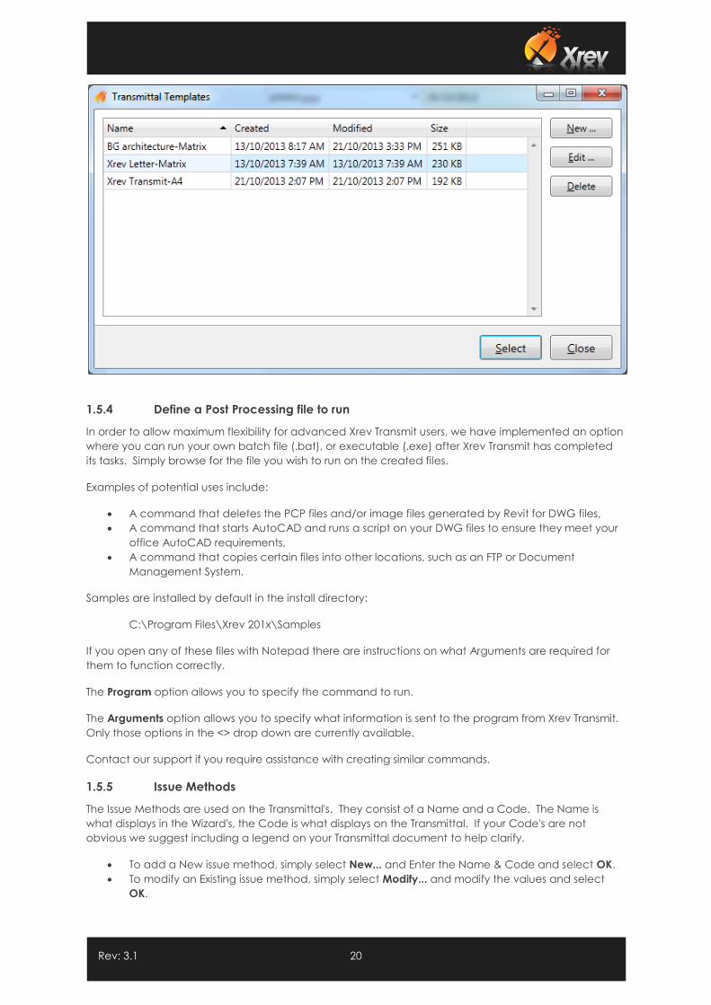
With Historical or Single Transmittal Transmittal Type selected the is no file path as the templates are
stored directly within the database. Select Change... to select from your customised transmittals, or
create New ones. Please refer to the Customising the Transmittal section for further information on how
to create Transmittals using the Report Designer.
Rev: 3.1 20
1.5.4 Define a Post Processing file to run
In order to allow maximum flexibility for advanced Xrev Transmit users, we have implemented an option
where you can run your own batch file (.bat), or executable (.exe) after Xrev Transmit has completed
its tasks. Simply browse for the file you wish to run on the created files.
Examples of potential uses include:
A command that deletes the PCP files and/or image files generated by Revit for DWG files,
A command that starts AutoCAD and runs a script on your DWG files to ensure they meet your
office AutoCAD requirements,
A command that copies certain files into other locations, such as an FTP or Document
Management System.
Samples are installed by default in the install directory:
C:\Program Files\Xrev 201x\Samples
If you open any of these files with Notepad there are instructions on what Arguments are required for
them to function correctly.
The Program option allows you to specify the command to run.
The Arguments option allows you to specify what information is sent to the program from Xrev Transmit.
Only those options in the <> drop down are currently available.
Contact our support if you require assistance with creating similar commands.
1.5.5 Issue Methods
The Issue Methods are used on the Transmittal's. They consist of a Name and a Code. The Name is
what displays in the Wizard's, the Code is what displays on the Transmittal. If your Code's are not
obvious we suggest including a legend on your Transmittal document to help clarify.
To add a New issue method, simply select New... and Enter the Name & Code and select OK.
To modify an Existing issue method, simply select Modify... and modify the values and select
OK.
Rev: 3.1 21
To delete an Existing issue method, simply select the Issue Method and select Delete... and
confirm the deletion by selecting Yes.
1.5.6 Issue Reasons
The Issue Reasons are used on the Transmittal's and in Naming Rules. They consist of a Name and a
Code. The Name is what displays in the Wizard's and in Naming Rules, the Code is what displays on the
Transmittal. If your Code's are not obvious we suggest including a legend on your Transmittal
document to help clarify.
To add a New issue reason, simply select New... and Enter the Name & Code and select OK.
To modify an Existing issue reason, simply select Modify... and modify the values and select OK.
To delete an Existing issue reason, simply select the Issue Method and select Delete... and
confirm the deletion by selecting Yes.
Use the Set Default option to specify which issue reason you'd like to show by default in all
issues. You can then change this during the wizard if you need to.
1.5.7 Paper Sizes
The Paper Sizes are used on the Transmittal's and in selection grids for Autodetecting Paper Size on
Printers. They consist of a Name, Code, Width & Height. The Name is what displays in the Wizard's, the
Code is what displays on the Transmittal, and the dimensions are used in translation of titleblock sizes to
determine what Paper Size they are. If your titleblock has not been drawn accurately, these may not
get interpreted correctly. In which case we recommend correcting your titleblock size.
If your Code's are not obvious we suggest including a legend on your Transmittal document to help
clarify.
To add a New paper size, simply select New... and Enter the Name , Code and dimensions and
select OK.
To modify an Existing paper size, simply select Modify... and modify the values and select OK.
To delete an Existing paper size, simply select the Issue Method and select Delete... and confirm
the deletion by selecting Yes.
Rev: 3.1 22
1.6 Set up Formats / Profiles
1.6.1 Profiles
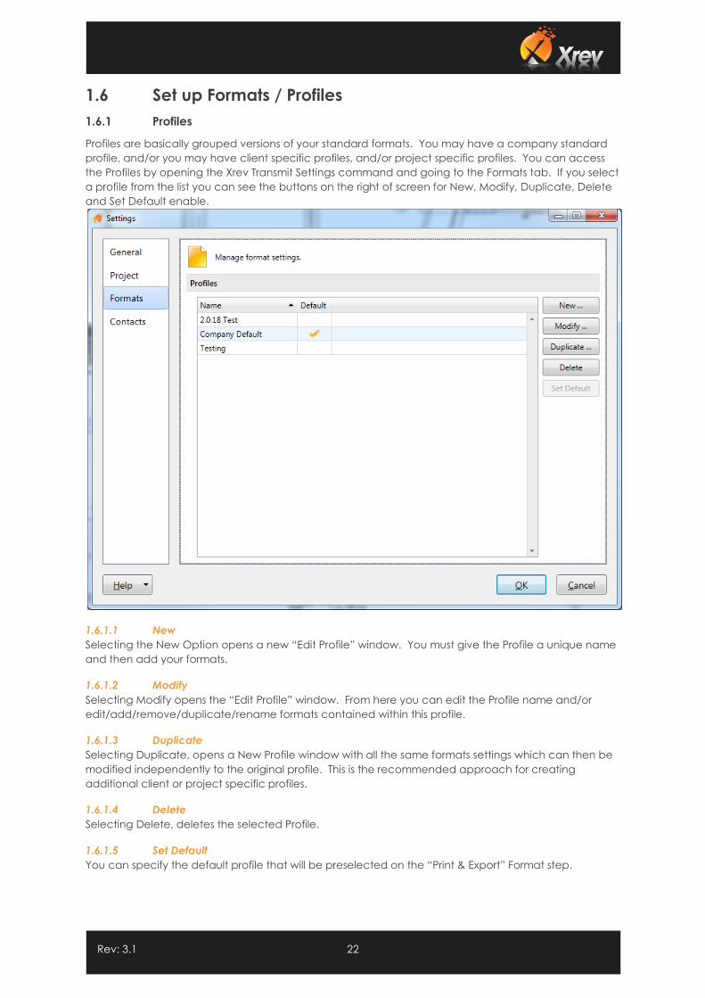
Profiles are basically grouped versions of your standard formats. You may have a company standard
profile, and/or you may have client specific profiles, and/or project specific profiles. You can access
the Profiles by opening the Xrev Transmit Settings command and going to the Formats tab. If you select
a profile from the list you can see the buttons on the right of screen for New, Modify, Duplicate, Delete
and Set Default enable.
1.6.1.1 New
Selecting the New Option opens a new “Edit Profile” window. You must give the Profile a unique name
and then add your formats.
1.6.1.2 Modify
Selecting Modify opens the “Edit Profile” window. From here you can edit the Profile name and/or
edit/add/remove/duplicate/rename formats contained within this profile.
1.6.1.3 Duplicate
Selecting Duplicate, opens a New Profile window with all the same formats settings which can then be
modified independently to the original profile. This is the recommended approach for creating
additional client or project specific profiles.
1.6.1.4 Delete
Selecting Delete, deletes the selected Profile.
1.6.1.5 Set Default
You can specify the default profile that will be preselected on the “Print & Export” Format step.
Rev: 3.1 23
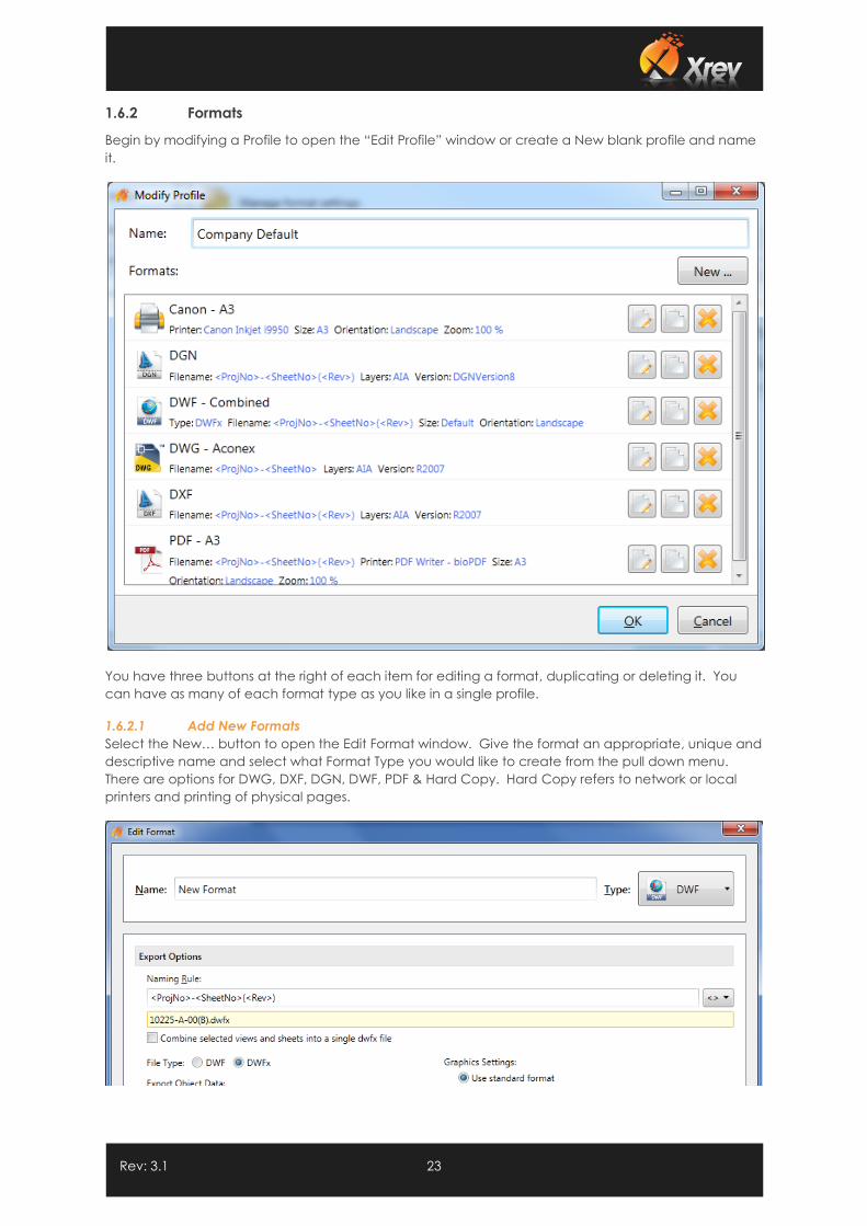
1.6.2 Formats
Begin by modifying a Profile to open the “Edit Profile” window or create a New blank profile and name
it.
You have three buttons at the right of each item for editing a format, duplicating or deleting it. You
can have as many of each format type as you like in a single profile.
1.6.2.1 Add New Formats
Select the New… button to open the Edit Format window. Give the format an appropriate, unique and
descriptive name and select what Format Type you would like to create from the pull down menu.
There are options for DWG, DXF, DGN, DWF, PDF & Hard Copy. Hard Copy refers to network or local
printers and printing of physical pages.
Rev: 3.1 24
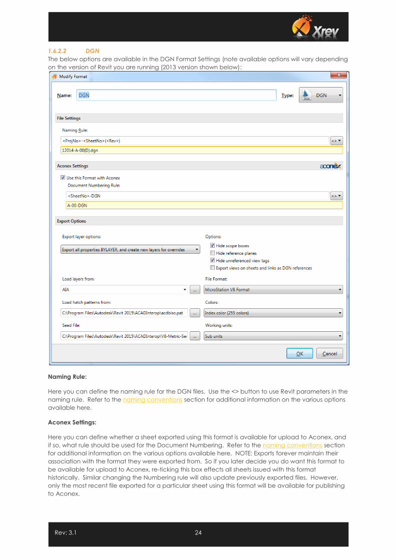
1.6.2.2 DGN
The below options are available in the DGN Format Settings (note available options will vary depending
on the version of Revit you are running (2013 version shown below):
Naming Rule:
Here you can define the naming rule for the DGN files. Use the <> button to use Revit parameters in the
naming rule. Refer to the naming conventions section for additional information on the various options
available here.
Aconex Settings:
Here you can define whether a sheet exported using this format is available for upload to Aconex, and
if so, what rule should be used for the Document Numbering. Refer to the naming conventions section
for additional information on the various options available here. NOTE: Exports forever maintain their
association with the format they were exported from. So if you later decide you do want this format to
be available for upload to Aconex, re-ticking this box effects all sheets issued with this format
historically. Similar changing the Numbering rule will also update previously exported files. However,
only the most recent file exported for a particular sheet using this format will be available for publishing
to Aconex.
Rev: 3.1 25
Export Layers Option:
Select one of the following Export layer options to specify how Revit elements with view-specific
graphic overrides will be mapped to CAD layers. (Graphic properties of Revit elements, such as colour,
line weight, and line style, are defined in the Object Styles of the categories to which the elements
belong, but these definitions can be overridden for a selected element in a specific view.)
Export category properties BYLAYER and overrides BYENTITY. A Revit element with view-specific graphic
overrides will retain those overrides in the CAD application, but will reside on the same CAD layer as
other entities in the same Revit category.
Export all properties BYLAYER, but do not export overrides. View-specific graphic overrides will be
ignored in the CAD application. Any exported Revit element will reside on the same CAD layer as other
entities in the same Revit category. By forcing all entities to display the visual properties defined by their
layer, this option results in a lower number of layers and provides by-layer control over the exported
DWG/DWF file.
Export all properties BYLAYER, and create new layers for overrides. A Revit element with view-specific
graphics will be placed on its own CAD layer. This option provides by-layer control over the exported
DGN file, and preserves graphical intent. However, it increases the number of layers in the exported
DGN file.
Load Hatch Patterns from:
Specify a hatch pattern (.pat) that is used in the file mapping table in the standard Revit Exports. Note
the mapping table is not accessible through the Revit API and as such is unable to be provided as an
option here.
Seed File:
Use the Browse button to specify the Seed File to be used for DGN exports.
File Format:
Specify the version of MicroStation to export in.
Colours:
Select either of the following options to specify how colours are exported to DGN files:
Index colour (255 Colours). For colours that are set by category, the indexed colours will be used. When
colours are not set by category and the override is preserved in the export, Revit uses the closest match
from the 255 indexed colours and thus may not provide an exact match for RGB and Pantone®
colours.
True colour (RGB Values). This uses the RGB value from Revit for the ByLayer and ByEntity parameters.
For example, when you export room (or space) colour fills, the colours in the exported file will exactly
match those in the original file.
Working Units:
Specify whether to export with Master or Sub Units.
Options:
You can select any or all of these options to hide the following types of Revit elements in the exported
file; Scope Boxes, Reference Planes, Unreferenced View Tags.

Rev: 3.1 26
If you want views placed on sheets or linked files in the project to be exported to a single file rather
than to several files that reference each other, make sure the Export views on sheets and links as DGN
references option is cleared.
NOTE: Upon export to V8 format, sheets are converted into sheet models in the DGN file. However, V7
format only supports one model, so even if the Export views on sheets and links as DGN references
option is selected, and referenced files are created, they will not be referenced to the host file.
Rev: 3.1 27
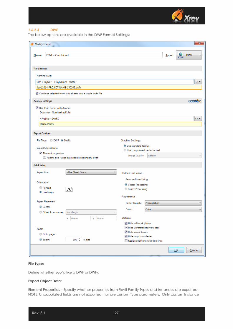
1.6.2.3 DWF
The below options are available in the DWF Format Settings:
File Type:
Define whether you’d like a DWF or DWFx
Export Object Data:
Element Properties – Specify whether properties from Revit Family Types and Instances are exported.
NOTE: Unpopulated fields are not exported, nor are custom Type parameters. Only custom Instance
Rev: 3.1 28
parameters are exported from Revit as at Revit 2012. Also, object data is only exported from views with
the visual style set to Wireframe or Hidden Line.
Rooms and Areas in a separate boundary layer – select this option if you want room and area
properties separately from the geometric representation, so that individual rooms and room data can
be viewed with facility management software (such as Autodesk® FMDesktop), or DWF markup
software (such as Autodesk® Design Review)
Graphics Settings:
Use standard format – Select this option if you want to export images as PNG files.
Use compressed raster format – Select this option if you want to export images as compressed PNG files
and specify the quality required.
Naming Convention:
Specify the naming convention required for DWF files. Use Revit and windows parameters in the file
name using the <> button. Refer to the naming conventions section for additional information.
Combine selected views and sheets into a single DWF file – select this option to have all the selected
sheets published to a single file.
NOTE: If you select this option you cannot use Revit sheet parameters in the naming convention.
Paper Size:
Specify what sheet size you are using or select the <Use Sheet Size> option to have the export
automatically handle varying size sheets by reading the title block size.
Orientation:
Specify whether the sheet orientation is to be Portrait or Landscape.
Paper Placement:
Specify how the revit sheet is positioned on the sheet. Either offset from the corner a nominated
amount or placed centrally.
Zoom:
Specify the scaling factor required.
Hidden Line Views:
Select whether Hidden Line views are to be processed as images (Raster) or as lines (vector). Vector is
generally quicker and of higher quality, but occasionally some information may not be printed, in
which case raster settings may be required on that particular sheet.
Appearance:
Specify the quality required of images/renderings captured on the sheets and whether the sheets are
to be processed in Black and White, Greyscale or Colour.
Options:
Hide ref/work planes – Automatically turn off reference planes so they don’t print/export
Hide unreferenced view tags – Automatically turn off any sections/elevations/callouts that have not
been placed on sheets yet.

Rev: 3.1 29
Replace halftone with thin lines – Automatically use thin lines for halftoned elements instead of a grey
scaled line.
Hide scope boxes – Automatically turn off any visible scope boxes so they don’t print/export
Hide crop boundaries – Automatically turn off any visible crop boundaries so they don’t print/export
Rev: 3.1 30
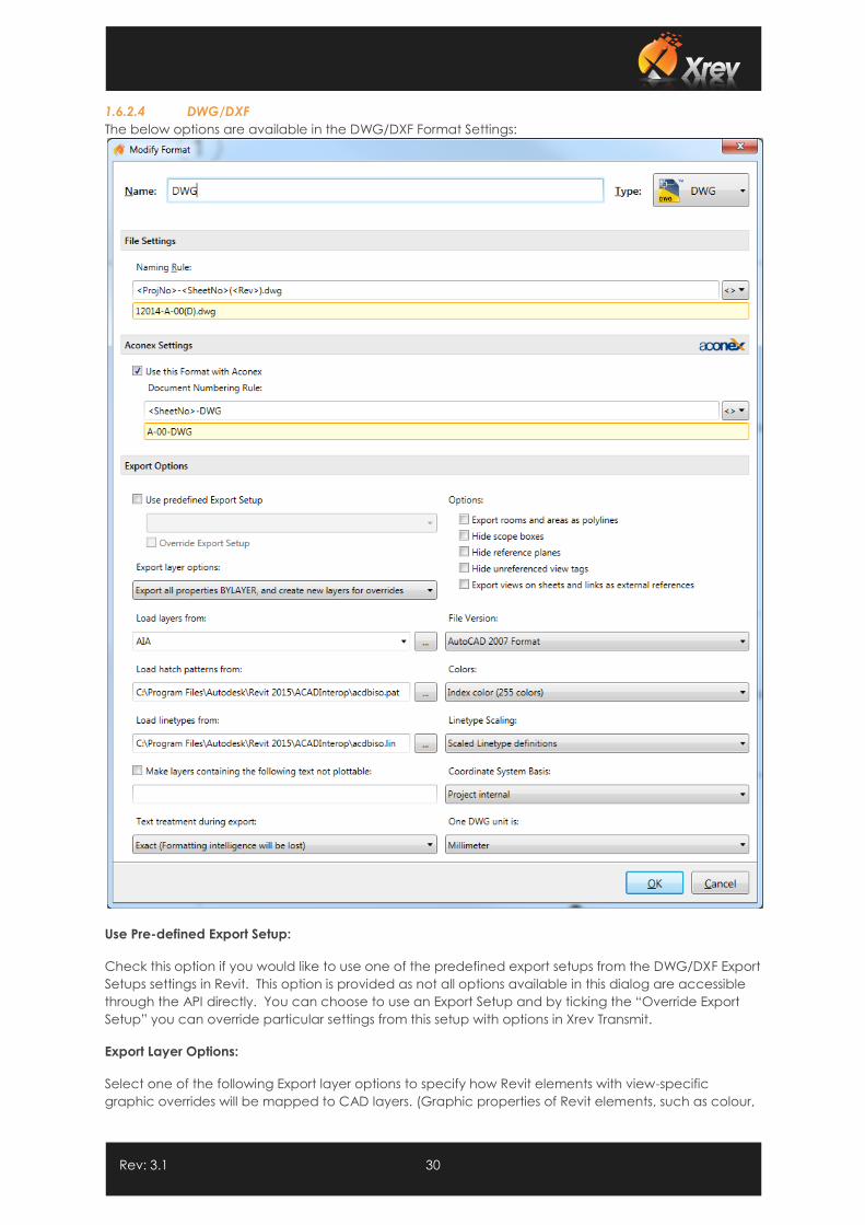
1.6.2.4 DWG/DXF
The below options are available in the DWG/DXF Format Settings:
Use Pre-defined Export Setup:
Check this option if you would like to use one of the predefined export setups from the DWG/DXF Export
Setups settings in Revit. This option is provided as not all options available in this dialog are accessible
through the API directly. You can choose to use an Export Setup and by ticking the “Override Export
Setup” you can override particular settings from this setup with options in Xrev Transmit.
Export Layer Options:
Select one of the following Export layer options to specify how Revit elements with view-specific
graphic overrides will be mapped to CAD layers. (Graphic properties of Revit elements, such as colour,
Rev: 3.1 31
line weight, and line style, are defined in the Object Styles of the categories to which the elements
belong, but these definitions can be overridden for a selected element in a specific view.)
Export category properties BYLAYER and overrides BYENTITY. A Revit element with view-specific graphic
overrides will retain those overrides in the CAD application, but will reside on the same CAD layer as
other entities in the same Revit category.
Export all properties BYLAYER, but do not export overrides. View-specific graphic overrides will be
ignored in the CAD application. Any exported Revit element will reside on the same CAD layer as other
entities in the same Revit category. By forcing all entities to display the visual properties defined by their
layer, this option results in a lower number of layers and provides by-layer control over the exported
DWG/DWF file.
Export all properties BYLAYER, and create new layers for overrides. A Revit element with view-specific
graphics will be placed on its own CAD layer. This option provides by-layer control over the exported
DWG/DXF file, and preserves graphical intent. However, it increases the number of layers in the
exported DWG file.
Load layers from:
Specify the layer mapping file to be used, either by selecting one of the standards from the drop down
or using the browse button to select your own.
Load Hatch Patterns from:
Specify a hatch pattern (.pat) that is used in the file mapping table in the standard Revit Exports. Note
the mapping table is not accessible through the Revit API and as such is unable to be provided as an
option here.
Load linetypes from:
Specify a linetypes file (.lin) that is used in the file mapping table in the standard Revit Exports. Note the
mapping table is not accessible through the Revit API and as such is unable to be provided as an
option here.
Make Layers containing the following text not plottable:
Any layers that can contain NPLT as defined in the Export Layers file will automatically be set as non-
plottable.
Text Treatment during Export:
From this drop-down list, select one of the following options:
Exact (Formatting intelligence will be lost). Exported text will look exactly as it does in Revit (exact line
wrapping). However, if the text includes bulleted or numbered lists, that paragraph functionality is lost
upon export. Pressing Enter within a formatted paragraph will not restore the formatting.
Approximate (Formatting intelligence will be maintained). If exported text includes bulleted or
numbered lists, that paragraph functionality is maintained when the text is edited. Pressing Enter within
a formatted paragraph will restore the formatting. However, the visual appearance of the text may
vary from the original, whether or not the note contains a list (that is, wrapping may vary).
Colours:
On the Colours tab of the Modify DWG/DXF Export Setup dialog, select either of the following options to
specify how colours are exported to DWG or DXF files:
Index colour (255 Colours). For colours that are set by category, the indexed colours specified on the
Layers tab of the Modify DWG/DXF Export Setup dialog will be used. When colours are not set by
Rev: 3.1 32
category and the override is preserved in the export, Revit uses the closest match from the 255 indexed
colours and thus may not provide an exact match for RGB and Pantone® colours.
True colour (RGB Values). Uses the RGB value from Revit for the ByLayer and ByEntity parameters, rather
than the indexed colour from the Layers tab of the Modify DWG/DXF Export Setup dialog. For example,
when you export room (or space) colour fills, the colours in the exported file exactly match those in the
original file.
Linetype Scaling:
In AutoCAD, the PSLTSCALE parameter controls paper space linetype scaling. A value of 0 indicates no
special linetype scaling. Linetype dash lengths are based on the drawing units of the space (model or
paper) in which the objects were created. A value of 1 indicates that viewport scaling governs linetype
scaling.
In Revit, the Linetype Scaling setting changes the default behaviour of the exported DWG files. Some
lines that you would expect to be dashed may now appear solid or in a different scale in either Model
or Sheet View in AutoCAD. Regardless of the option you choose, the DWG linetype definitions are
created so that a dashed line always begins and ends with a dash.
You can select any of the following options to control the LTSCALE and PSLTSCALE settings in AutoCAD
and to control how linetype definitions are exported from Revit:
Scaled Linetype definitions. This option preserves graphical intent by exporting linetypes the same as
they were previously scaled by view scale.
Modelspace (PSLTSCALE = 0). This option sets the LTSCALE parameter to view scale and the PSLTSCALE
to 0.
Paperspace (PSLTSCALE = 1). This option sets the value of both LTSCALE and PSLTSCALE to 1. Revit
linetype definitions are scaled to reflect project units, but otherwise they are exported as is.
File Version:
Select what version of AutoCAD you wish to export the DWG/DXF to.
Coordinate System Basis:
Select where you want to export with the Project Internal coordinates or the shared coordinates. NOTE:
The Shared Coordinates setting has no effect when exporting Sheets.
One DWG unit is:
Specify the exported DWG/DXF unit system.
Export Views on Sheets and Links as External References (DWG only):
Specify whether each view on the sheet will be exported as an individual file and Xref’d to the sheet file
or as a single file. NOTE: There are no naming controls for the Xref’d views currently available in Xrev
Transmit or through the Revit API.
Export rooms and areas as polylines:
Select the Export rooms and areas as polylines option if you want rooms and areas to be exported to a
DWG or DXF file as closed polylines.
Area polylines are generated from area plan views only.
Room polylines are generated from floor plan views or ceiling plan views only.
Options:

Rev: 3.1 33
You can select any or all of these options to hide the following types of Revit elements in the exported
file; Scope Boxes, Reference Planes, Unreferenced View Tags.
Rev: 3.1 34
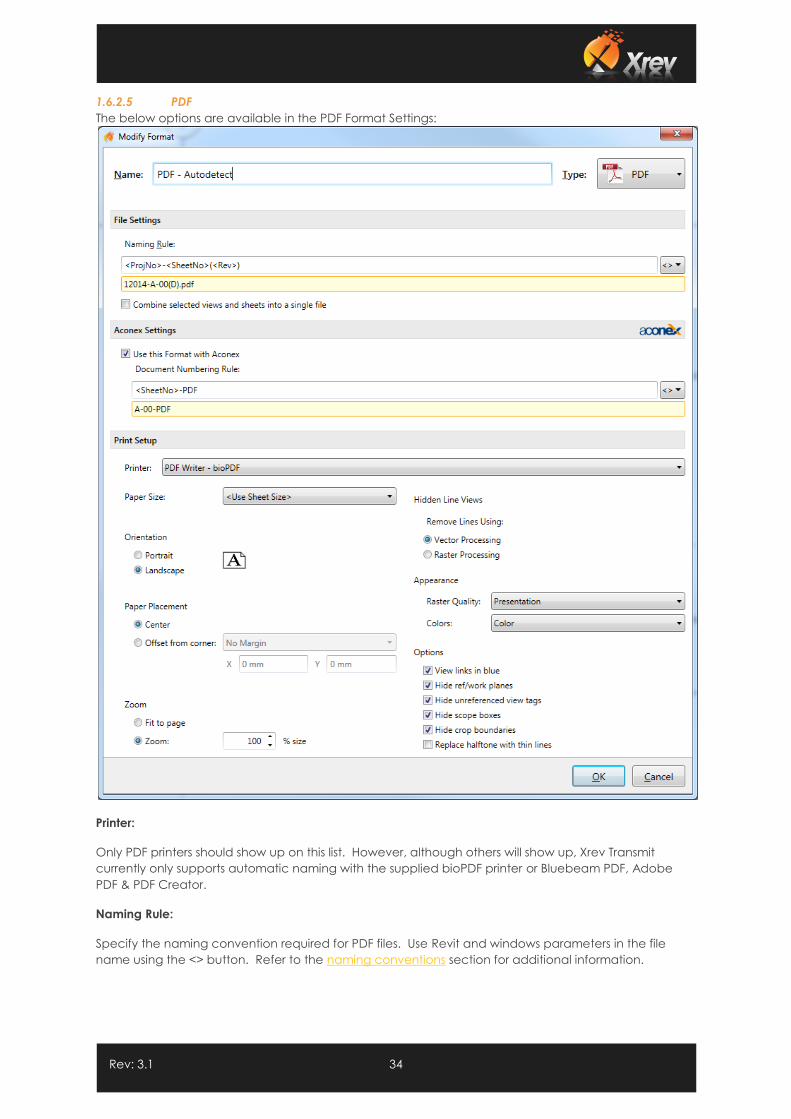
1.6.2.5 PDF
The below options are available in the PDF Format Settings:
Printer:
Only PDF printers should show up on this list. However, although others will show up, Xrev Transmit
currently only supports automatic naming with the supplied bioPDF printer or Bluebeam PDF, Adobe
PDF & PDF Creator.
Naming Rule:
Specify the naming convention required for PDF files. Use Revit and windows parameters in the file
name using the <> button. Refer to the naming conventions section for additional information.
Rev: 3.1 35
Combine selected views and sheets into a single pdf file – select this option to have all the selected
sheets published to a single file. Naturally if you select this option you cannot use Revit sheet
parameters in the naming convention.
Paper Size:
Specify what sheet size you are using for this format. Select <Use Sheet Size> for auto-detect.
Orientation:
Specify whether the sheet orientation is to be Portrait or Landscape.
Paper Placement:
Specify how the Revit sheet is positioned on the sheet. Either offset from the corner a nominated
amount or placed centrally.
Zoom:
Specify the scaling factor required.
Hidden Line Views:
Select whether Hidden Line views are to be processed as images (Raster) or as lines (vector). Vector is
generally quicker and of higher quality, but occasionally some information may not be printed, in
which case raster settings may be required on that particular sheet.
Appearance:
Specify the quality required of images/renderings captured on the sheets and whether the sheets are
to be processed in Black and White, Greyscale or Colour.
Options:
View links in blue – Display level, section marker, elevation markers, callout markers as blue when they
are a hyperlink.
Hide ref/work planes – Automatically turn off reference planes so they don’t print/export
Hide unreferenced view tags – Automatically turn off any sections/elevations/callouts that have not
been placed on sheets yet.
Replace halftone with thin lines – Automatically use thin lines for halftoned elements instead of a grey
scaled line.
Hide scope boxes – Automatically turn off any visible scope boxes so they don’t print/export
Hide crop boundaries – Automatically turn off any visible crop boundaries so they don’t print/export
Rev: 3.1 36
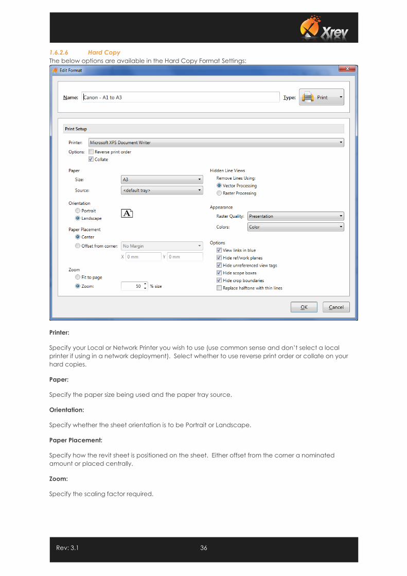
1.6.2.6 Hard Copy
The below options are available in the Hard Copy Format Settings:
Printer:
Specify your Local or Network Printer you wish to use (use common sense and don’t select a local
printer if using in a network deployment). Select whether to use reverse print order or collate on your
hard copies.
Paper:
Specify the paper size being used and the paper tray source.
Orientation:
Specify whether the sheet orientation is to be Portrait or Landscape.
Paper Placement:
Specify how the revit sheet is positioned on the sheet. Either offset from the corner a nominated
amount or placed centrally.
Zoom:
Specify the scaling factor required.
Rev: 3.1 37
Hidden Line Views:
Select whether Hidden Line views are to be processed as images (Raster) or as lines (vector). Vector is
generally quicker and of higher quality, but occasionally some information may not be printed, in
which case raster settings may be required on that particular sheet.
Appearance:
Specify the quality required of images/renderings captured on the sheets and whether the sheets are
to be processed in Black and White, Greyscale or Colour.
Options:
View links in blue – Display level, section marker, elevation markers, callout markers as blue when they
are a hyperlink.
Hide ref/work planes – Automatically turn off reference planes so they don’t print/export
Hide unreferenced view tags – Automatically turn off any sections/elevations/callouts that have not
been placed on sheets yet.
Replace halftone with thin lines – Automatically use thin lines for halftoned elements instead of a grey
scaled line.
Hide scope boxes – Automatically turn off any visible scope boxes so they don’t print/export
Hide crop boundaries – Automatically turn off any visible crop boundaries so they don’t print/export
Rev: 3.1 38
1.7 Output Locations
This section outlines how to use the various Output locations options in the Xrev Transmit settings.
1.7.1 Browse to a Folder
The most obvious way to set your output location is to use the folder button and browse to the specific
folder where you want the files to be saved. However, there are much better ways to set output
locations in Xrev Transmit than using the browse button. The issue with this option is for each new
project you more than likely need to reset the output location each time.
1.7.2 Using Revit Parameters
You can use the Browse to a folder option initially, we then suggest modifying project specific folder
structures by swapping out Revit parameter tokens which can be placed using the <> button. This
essentially means that these parts will parametrically update based upon the settings in the Revit file,
eliminating the need to edit the Output Locations each time. Basically you can set once and forget
about them provided you have a standard folder structure.
Valid tokens currently are either from the Project Information category or Sheet category:
Default Output Location, Project Output Location, Transmittal Naming Rule:
<ProjName> - Revit Project Name
<ProjNo> - Revit Project Number
<ProjStatus> - Revit Project Status
<ProjIssueDate> - Revit Project Issue Date
<IssueName> - Xrev Transmit Issue Name
<IssueReason> - Xrev Transmit Issue Reason
<Date> - Current Date from the System
<ComputerName> - Computer Name from the System
<UserName> - User Name from the System
<UserDomain> - User Domain from the System
+ Any custom project information category parameters you have added, just select from the
pull down tag list...
Rev: 3.1 39
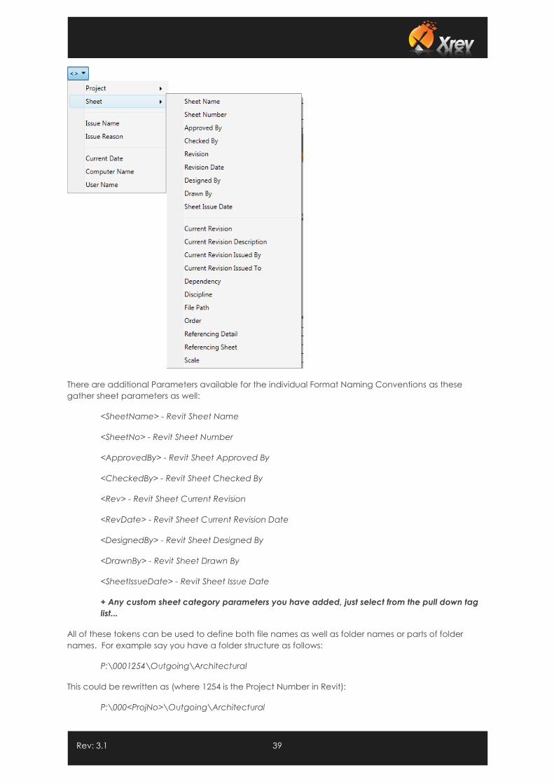
There are additional Parameters available for the individual Format Naming Conventions as these
gather sheet parameters as well:
<SheetName> - Revit Sheet Name
<SheetNo> - Revit Sheet Number
<ApprovedBy> - Revit Sheet Approved By
<CheckedBy> - Revit Sheet Checked By
<Rev> - Revit Sheet Current Revision
<RevDate> - Revit Sheet Current Revision Date
<DesignedBy> - Revit Sheet Designed By
<DrawnBy> - Revit Sheet Drawn By
<SheetIssueDate> - Revit Sheet Issue Date
+ Any custom sheet category parameters you have added, just select from the pull down tag
list...
All of these tokens can be used to define both file names as well as folder names or parts of folder
names. For example say you have a folder structure as follows:
P:\0001254\Outgoing\Architectural
This could be rewritten as (where 1254 is the Project Number in Revit):
P:\000<ProjNo>\Outgoing\Architectural
Rev: 3.1 40
1.7.3 Absolute Paths
An absolute path is a folder path that is complete on its own. For instance, a mapped drive location or
a UNC folder path… You can actually place an absolute path in any of the following sections. This
doesn’t mean you should, it’s just that technically it’s supported:
Global Default Output Location
Transmittal Naming Convention
Project Output Location (Override)
All Format Naming Conventions (DWG, PDF, DWF, DXF, DGN)
So what does that mean? Basically by placing a full file path for one of the naming conventions it
overrides the Global Default Output Location and/or the Project Output Location.
1.7.4 Accumulative Paths
An accumulative folder path is only part of the folder structure and it is combined with other sections in
order to create the full file path. The Global Default Output Location must be an absolute path.
For Example:
Global Default Output Location = C:\My Projects\<ProjNo>
Transmittal Naming Convention = Issued\Transmittals\<ProjNo>-DocTrans-<Date>
Accumulates to give C:\My Projects\<ProjNo>\Issued\Transmittals\<ProjNo>-DocTrans-<Date>.docx
as my effective output location for my transmittals. This modularisation means that all output locations
can be achieved in a parametric fashion.
1.7.5 Outputting Specific Formats to Individual Folders
By inputting folder names into the naming convention fields for each format type it is possible to output
these formats to their own individual folders.
For Example:
Global Default Output Location = C:\My Projects\<ProjNo>\Issued\<Date>-
<ProjStatus>
A1 PDF Format Naming Convention = PDF\<ProjNo>-<SheetNo>(<Rev>).pdf
Accumulates to give:
C:\My Projects\<ProjNo>\Issued\<Date>-<ProjStatus>\ PDF\<ProjNo>-<SheetNo>(<Rev>).pdf
With the fields substituted with the Revit Project Parameter values:
C:\My Projects\2011_106\Issued\110616-TENDER\ PDF\2011_106-A205(3).pdf
Similarly, if you want a PDF set to go in a completely different location, for instance a copy to an FTP site
you can use absolute paths.
For Example:
Global Default Output Location = C:\My Projects\<ProjNo>\Issued\<Date>-
<ProjStatus>
A1 PDF Format Naming Convention = F:\<ProjNo>\<Date>\<ProjNo>-
<SheetNo>(<Rev>).pdf
In this case, the PDF location overrides the global default output location and as such it is ignored.
Rev: 3.1 41
1.7.6 Microsoft Windows Variables
Xrev supports using Microsoft Windows environment variables in your naming conventions and output
locations as well.
For Example:
%ALLUSERSPROFILE%
%LOCALAPPDATA%
%APPDATA%
%PROGRAMFILES%
%PROGRAMDATA%
%SYSTEMDRIVE%
%USERNAME%
%USERPROFILE%
1.8 Naming Conventions
The Naming Conventions in Xrev Transmit can also define the Output Locations. Basically the tokens
and text after the last backslash will define the file name. Please refer to the Output Locations section
for examples of Naming Conventions and valid Revit Parameter tokens. Correct use of these will ensure
you can set and forget all the settings in Xrev Transmit.
These placeholder tags have advanced functionality such as Alignment of values, Formatting of
values, Prefix/Suffix to values, Nominating a value as optional, specifying a default value.
The full syntax is as follows:
<[Prefix]NameSpace.ParameterName,Alignment:Format[Suffix]?=DefaultValue>
You can just insert the ones you need, but they must be in this order. For example, you can't put
Default Value before the suffix.
1.8.1 Prefix/Suffix
A prefix/suffix value is not inserted if the parameter is blank and not used if a DefaultValue is specified.
Simply surround each Prefix/Suffix with Square brackets. For example:
<[(]Revision[)]>
If my Revision was A the result would be:
(A)
If my Revision was blank nothing would be inserted.
1.8.2 Formatting
Numeric and date parameters can be formatted in the placeholder using a Colon. For Example:
<Date:yy-MM-dd> and <Number:000>
If the date was 26/10/2013 and the Number was 6 the result would be:
13-10-26 and 006
Rev: 3.1 42
1.8.3 Alignment
Using the alignment option you can pad out a value to a certain number of characters using spaces
with a comma. For example:
<ProjectNumber>-<SheetNumber,10>(<Revision>)
If Project Number was 1000, Sheet Number was A001 and Revision was A the result would be:
1000- A001(A)
<ProjectNumber>-<SheetNumber,-10>(<Revision>)
1000-A001 (A)
1.8.4 Optional Variables
If you want to use a parameter in a naming rule, but don't care if doesn't exist then you can simply add
question mark. This is very useful when using custom shared parameters or when some values are going
to be blank. For example:
<Discipline?>
If the Discipline parameter didn't exist in the project or was blank, the value would just be
ignored. If you didn't nominate this as optional, Xrev Transmit would consider the parameter
not existing or being blank as an error. This is to ensure file paths are always valid.
1.8.5 Default Values
Default Values are very useful to apply a value to input when the parameter value is blank. Default
Values ignore Prefix, Suffix and Format. For Example:
<ProjectNumber>-<SheetNumber>-<[(]Revision=-Not For Issue[)]>
If my Revision was blank the result would be:
1000-A001-Not For Issue
1.8.6 Namespace
If you have two parameters with the same name in Revit then you can use the Namespace to
differentiate between them. For example, the parameter for the project's name is Name as is the
parameter for the sheet's name. You can use the namespace to pick between them by using:
<Project.Name> or <Sheet.Name>
Possible namespaces are Sheet, Project, Issue & System
Rev: 3.1 43
1.9 Customising the Transmittal
Xrev Transmit can utilise two different Transmittal types:
1. Microsoft Word 2007/2010 template file (.DOCX) - Per Issue Transmittals only
2. Built In Report Designer - Per Issue and Matrix Transmittals
1.9.1 Editing the Transmittal in Word
An example transmittal is supplied as part of the installation of which you are welcome to customise as
you need to match your own company standards. However, we suggest making a copy just in case
you make a mistake. This sample document can be found here, and if doing a network deployment
should be moved to a central location so everyone uses the same template:
C:\ProgramData\Xrev\Transmittal Template.docx (Windows 7 & Vista)
NOTE: Xrev Transmit does not support Microsoft Word 2003. Xrev Transmit cannot do historical
transmittals using the Word Template.
Please make a copy of the Transmittal before making any edits,
1. Open the Transmittal Template.docx file in Microsoft Word 2007 or later.
2. By default the Transmittal consists of 4 tables and a header/footer.
3. You may edit the header/footer as you require using standard features. There is nothing
particularly special about this. So swap out images, or remove them all together and standard
word field codes for document numbering etc. Or leave the header and footer blank if you
like.
4. The trickier bits and the parts that Xrev Transmit is interested in are contained within the tables.
5. This word document has been setup using Word Styles, Color Themes and Fonts Themes. As
such you can very quickly make modifications to suit your standards by changing the Themes
to match your own office standards.
6. Go to the Layout tab, and the Themes panel.
7. Use the Colors pull down to edit the colour themes.
8. Use the Fonts pull down to edit the fonts used for Headings and Body text.
9. Now that you have set the Fonts and Colours to suit your needs you can begin modifying the
table styles.
10. The Project Information table and Transmittal Information table don’t actually need to exist. All
the “Plain Text Content Controls” used here can exist outside of the table if you prefer.
11. The Distribution List table and Documentation List tables must remain in tables as this is critical to
how Xrev Transmit generates all the extra rows. These tables must always be laid out so only
one Recipient occupies each row and only one sheet occupies each row.
12. That said you can re-order the columns as you see fit and remove tags/columns that you do
not require.
13. The “Plain Text Content Controls” can be copied around or you can place new ones from
scratch – however only ones supplied within the sample document are supported. To place
new controls you must enable the Developer tab in word. This is done through
FileOptionsCustomise Ribbon and then checking Developer in the right hand pane (Word
2010).
14. With the developer tab enabled if you select one of the controls you can open the Properties
of one of these controls. The most important part for Xrev Transmit to successfully substitute
these fields is the “Tag” field must match what we supply. If this doesn’t match exactly the field
will not be substituted.
15. To edit the table styles enable the Styles window and choose Modify Styles,
16. The Project Information and Transmittal Information tables use the Cadway Table style, so
modify the settings of this table as needed to suit your requirements.
17. The Distribution List and Documentation List tables use Cadway Table 2 style, so similar modify
its settings as needed to suit your requirements. These tables are set to repeat the header row
when spanning multiple pages.
Rev: 3.1 44
18. Or course all other text, headings etc. can be changed as you require and additional
disclaimers added as you see fit.
19. Hopefully this is enough information to get you started, if you aren’t that familiar with Microsoft
Word then there are some great resources on the internet. But failing this please don’t hesitate
to contact our support team and see if they can assist reproducing your requirement.
1.9.2 Creating a New Transmittal using the Report Designer
Xrev Transmit has a built in Report Designer, for designing and customising your Transmittal. To access
the Report Designer simply select your Transmittal Type as Historical Transmittal or Single Transmittal.
NOTE: With Historical Transmittal you can only create a Historical Transmittal and with Single Transmittal
you can only create a Single Transmittal.
With the correct transmittal type selected choose Change...
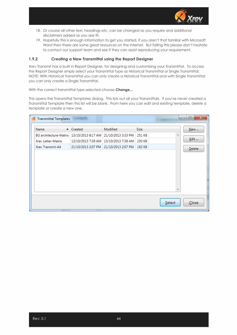
This opens the Transmittal Templates dialog. This lists out all your Transmittals. If you've never created a
Transmittal Template then this list will be blank. From here you can edit and existing template, delete a
template or create a new one.
Rev: 3.1 45
1.9.2.1 Creating a New Transmittal
1. Begin by selecting New...
2. We recommend using one of our templates as basis, to help guide you on how the template
should be setup, although its not required and you can choose not to use a template. You
can select between our A4 or Letter template. In this tutorial we'll select "Default template on
A4 paper".
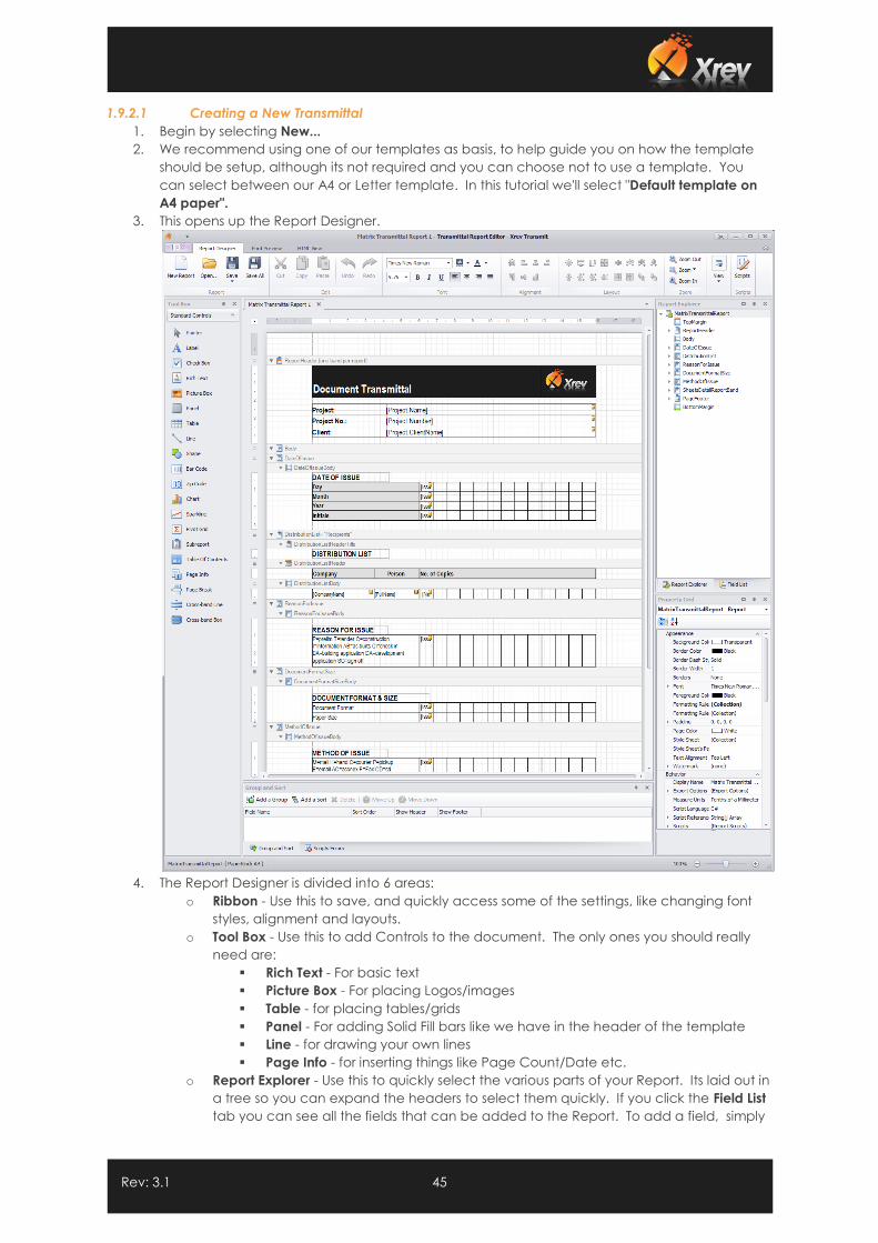
3. This opens up the Report Designer.
4. The Report Designer is divided into 6 areas:
o Ribbon - Use this to save, and quickly access some of the settings, like changing font
styles, alignment and layouts.
o Tool Box - Use this to add Controls to the document. The only ones you should really
need are:
Rich Text - For basic text
Picture Box - For placing Logos/images
Table - for placing tables/grids
Panel - For adding Solid Fill bars like we have in the header of the template
Line - for drawing your own lines
Page Info - for inserting things like Page Count/Date etc.
o Report Explorer - Use this to quickly select the various parts of your Report. Its laid out in
a tree so you can expand the headers to select them quickly. If you click the Field List
tab you can see all the fields that can be added to the Report. To add a field, simply
Rev: 3.1 46
drag it from the field list onto your report where it will automatically embed itself in a
cell of a table or create a label. You can then customise its properties.
o Property Grid - This contains all the properties and options available for the selected
element. Use this for adding background colors to cells, changing text
alignment/justification, borders, padding, widths and heights, etc. This is the most
accurate way to set settings.
o Document tab Window - this is where you actually design your report and place all the
components.
o Group and Sort - you won't need to use these
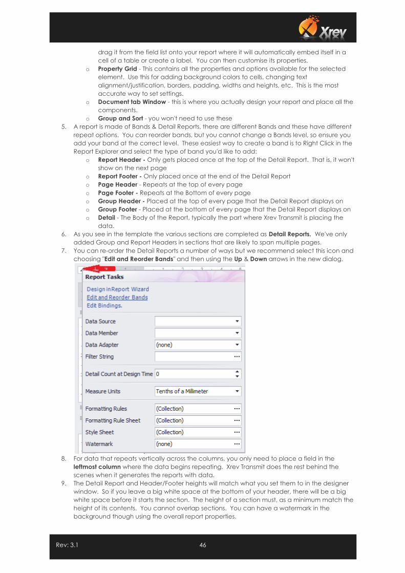
5. A report is made of Bands & Detail Reports, there are different Bands and these have different
repeat options. You can reorder bands, but you cannot change a Bands level, so ensure you
add your band at the correct level. These easiest way to create a band is to Right Click in the
Report Explorer and select the type of band you'd like to add:
o Report Header - Only gets placed once at the top of the Detail Report. That is, it won't
show on the next page
o Report Footer - Only placed once at the end of the Detail Report
o Page Header - Repeats at the top of every page
o Page Footer - Repeats at the Bottom of every page
o Group Header - Placed at the top of every page that the Detail Report displays on
o Group Footer - Placed at the bottom of every page that the Detail Report displays on
o Detail - The Body of the Report, typically the part where Xrev Transmit is placing the
data.
6. As you see in the template the various sections are completed as Detail Reports. We've only
added Group and Report Headers in sections that are likely to span multiple pages.
7. You can re-order the Detail Reports a number of ways but we recommend select this icon and
choosing "Edit and Reorder Bands" and then using the Up & Down arrows in the new dialog.
8. For data that repeats vertically across the columns, you only need to place a field in the
leftmost column where the data begins repeating. Xrev Transmit does the rest behind the
scenes when it generates the reports with data.
9. The Detail Report and Header/Footer heights will match what you set them to in the designer
window. So if you leave a big white space at the bottom of your header, there will be a big
white space before it starts the section. The height of a section must, as a minimum match the
height of its contents. You cannot overlap sections. You can have a watermark in the
background though using the overall report properties.
Rev: 3.1 47
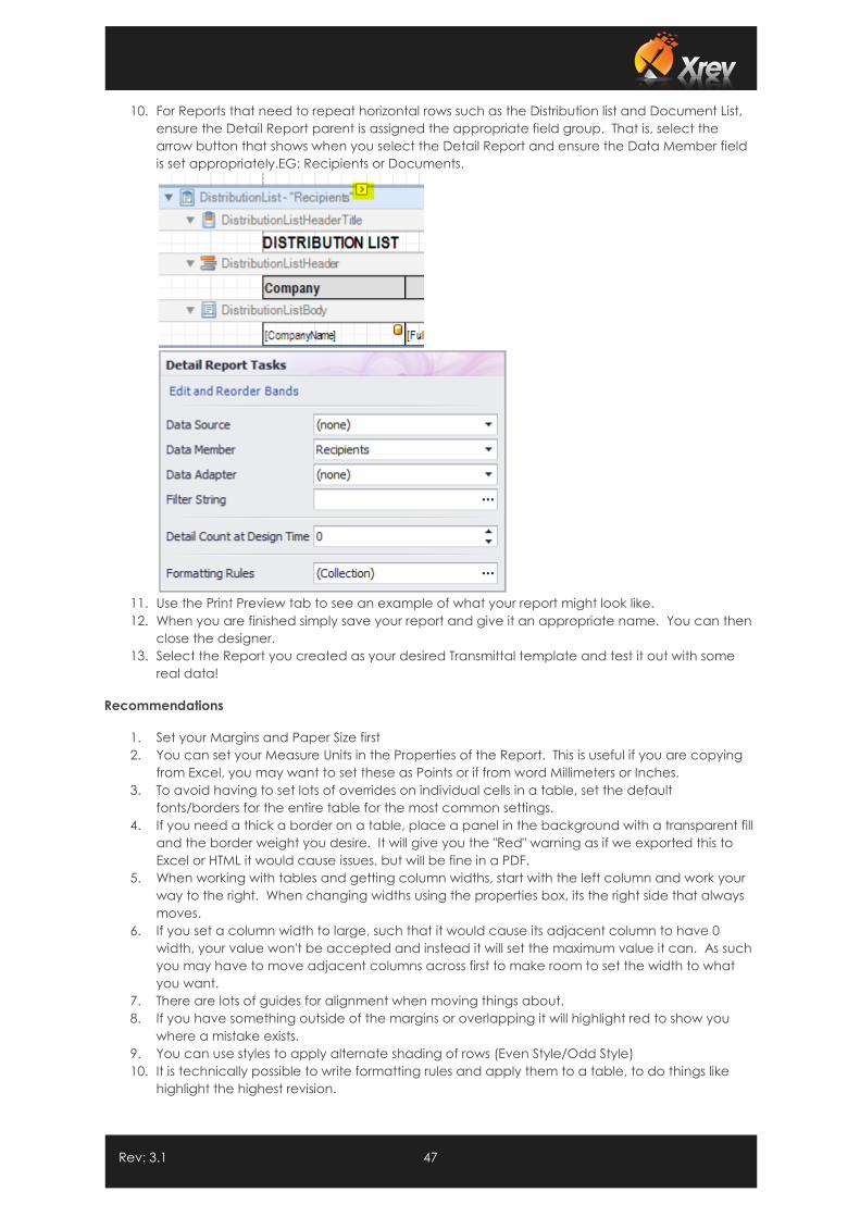
10. For Reports that need to repeat horizontal rows such as the Distribution list and Document List,
ensure the Detail Report parent is assigned the appropriate field group. That is, select the
arrow button that shows when you select the Detail Report and ensure the Data Member field
is set appropriately.EG: Recipients or Documents.
11. Use the Print Preview tab to see an example of what your report might look like.
12. When you are finished simply save your report and give it an appropriate name. You can then
close the designer.
13. Select the Report you created as your desired Transmittal template and test it out with some
real data!
Recommendations
1. Set your Margins and Paper Size first
2. You can set your Measure Units in the Properties of the Report. This is useful if you are copying
from Excel, you may want to set these as Points or if from word Millimeters or Inches.
3. To avoid having to set lots of overrides on individual cells in a table, set the default
fonts/borders for the entire table for the most common settings.
4. If you need a thick a border on a table, place a panel in the background with a transparent fill
and the border weight you desire. It will give you the "Red" warning as if we exported this to
Excel or HTML it would cause issues, but will be fine in a PDF.
5. When working with tables and getting column widths, start with the left column and work your
way to the right. When changing widths using the properties box, its the right side that always
moves.
6. If you set a column width to large, such that it would cause its adjacent column to have 0
width, your value won't be accepted and instead it will set the maximum value it can. As such
you may have to move adjacent columns across first to make room to set the width to what
you want.
7. There are lots of guides for alignment when moving things about.
8. If you have something outside of the margins or overlapping it will highlight red to show you
where a mistake exists.
9. You can use styles to apply alternate shading of rows (Even Style/Odd Style)
10. It is technically possible to write formatting rules and apply them to a table, to do things like
highlight the highest revision.
Rev: 3.1 48
1.10 Updating Xrev Transmit
Updating Xrev Transmit when a new version comes out couldn’t be simpler. Simply download the
installer from the website (the trial and full version installer are the exact same file). Run the installer with
Administrator privileges, follow the prompts and your Xrev Transmit will be updated to the current
version in a matter of seconds.
NOTE: If you are using a shared database, ensure you update all workstations at the same time! If the
database is a different version to the installed version trying to read the database you may experience
errors.
If you experience any issues updating Xrev Transmit please don’t hesitate to contact our support team.
1.11 Deploying a Network Setup
There are 2 ways to setup shared settings throughout an office. Manually or using a command line to
run the installer.
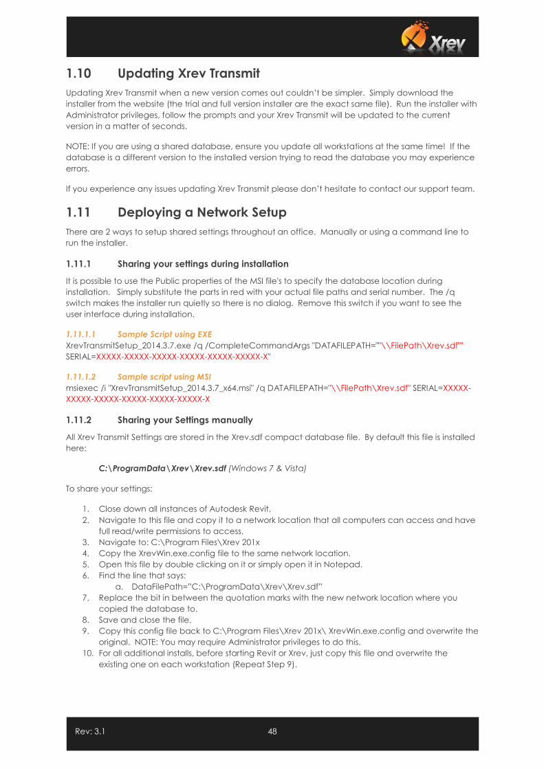
1.11.1 Sharing your settings during installation
It is possible to use the Public properties of the MSI file's to specify the database location during
installation. Simply substitute the parts in red with your actual file paths and serial number. The /q
switch makes the installer run quietly so there is no dialog. Remove this switch if you want to see the
user interface during installation.
1.11.1.1 Sample Script using EXE
XrevTransmitSetup_2014.3.7.exe /q /CompleteCommandArgs "DATAFILEPATH=""\\FilePath\Xrev.sdf""
SERIAL=XXXXX-XXXXX-XXXXX-XXXXX-XXXXX-XXXXX-X"
1.11.1.2 Sample script using MSI
msiexec /i "XrevTransmitSetup_2014.3.7_x64.msi" /q DATAFILEPATH="\\FilePath\Xrev.sdf" SERIAL=XXXXX-
XXXXX-XXXXX-XXXXX-XXXXX-XXXXX-X
1.11.2 Sharing your Settings manually
All Xrev Transmit Settings are stored in the Xrev.sdf compact database file. By default this file is installed
here:
C:\ProgramData\Xrev\Xrev.sdf (Windows 7 & Vista)
To share your settings:
1. Close down all instances of Autodesk Revit,
2. Navigate to this file and copy it to a network location that all computers can access and have
full read/write permissions to access.
3. Navigate to: C:\Program Files\Xrev 201x
4. Copy the XrevWin.exe.config file to the same network location.
5. Open this file by double clicking on it or simply open it in Notepad.
6. Find the line that says:
a. DataFilePath=”C:\ProgramData\Xrev\Xrev.sdf”
7. Replace the bit in between the quotation marks with the new network location where you
copied the database to.
8. Save and close the file.
9. Copy this config file back to C:\Program Files\Xrev 201x\ XrevWin.exe.config and overwrite the
original. NOTE: You may require Administrator privileges to do this.
10. For all additional installs, before starting Revit or Xrev, just copy this file and overwrite the
existing one on each workstation (Repeat Step 9).
Rev: 3.1 49
1.11.3 Quickly Copy Settings to Multiple Computers
You can very easily create a batch file that copies this file for you, to save time navigating around the
folders. This way it should only take a few seconds to update each workstation that Xrev Transmit is
installed on.
1. To do this create a new text file and change the file extension from .txt to .bat,
2. Right Click and Edit the batch file,
3. Add the following strings, but substitute the part in RED with your actual file location.
xcopy /y “\\server\Xrev Settings\ XrevWin.exe.config” “C:\Program Files\Xrev 201x\”
Pause
4. Save the file.
5. You will still need Administrator privileges to run this batch file though.
6. Run the batch file on each machine by double clicking it.
NOTE: The XrevWin.exe.config file is version specific. During a standard install this file is upgraded. So
after each upgrade, ensure to recopy this file back to your shared location, to prevent overwriting a
newer config with an older version. Otherwise, you will receive an error message on load.
Rev: 3.1 50
1.12 Project Overrides
Sometimes you may have a particular project that may need to use different settings than your office
standard. In the Settings dialog, this is the purpose of the Project tab.
If values are set here they override the equivalent settings on the General tab.
1.12.1 Settings stored by Project Number
It is important to note that settings made on the Project tab are only applicable to the Project Number
of the Revit file you currently have open. If you open another project with a different Project Number in
Revit then these settings will be blank again.
This is as intended, as these settings should only really need to be used under special circumstances.
1.12.2 Project Default Output Location
Enter your Output Location here to either override the global output location or append to it. This is
useful if you have a project using a different folder structure to your current standard, or other special
circumstance when files need to be ordered differently…
1.12.3 Project Default Profile
For each project you can set the default format profile to use. This way as a Revit Manager, you can
ensure your team is using the correct PDF, DWG, DWF etc settings for this particular project. Again this
setting is stored by Project Number.
1.12.4 Custom Revision Parameter
For this project, define whether to use the option defined in the general settings, you can override and
set a different revision parameter to use, or you can choose to use the standard revision parameter.
1.12.5 Post Processing
In this section you have 3 options. You can choose to use the post processing option defined in the
general settings, you can override and set a different post processing file, or you can disable post
processing on this particular project all together. Please refer to the General Settings, post processing
feature for further information on this option.
1.12.6 Aconex Settings
Here you can login to Aconex and associate the correct Aconex Instance (location) and Aconex
Project so it's automatically selected during the Aconex wizard.
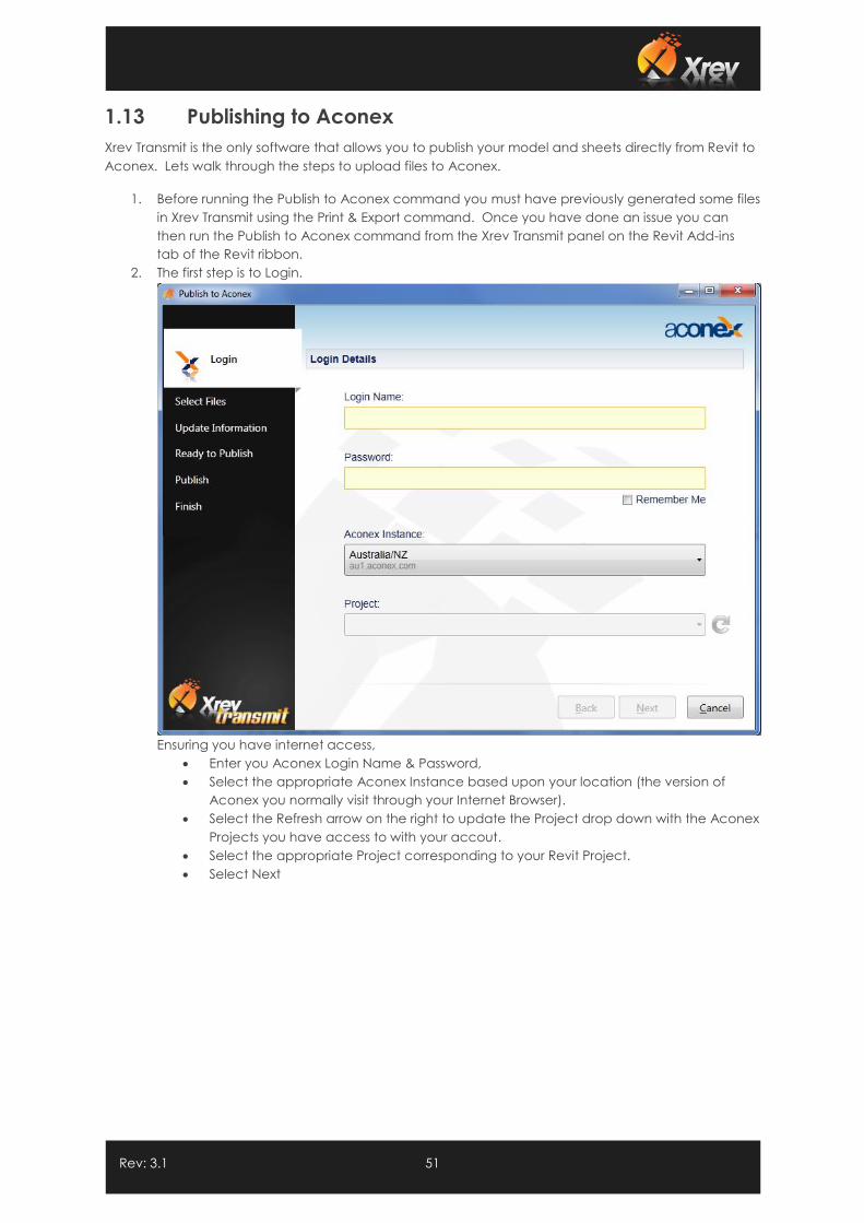
Rev: 3.1 51
1.13 Publishing to Aconex
Xrev Transmit is the only software that allows you to publish your model and sheets directly from Revit to
Aconex. Lets walk through the steps to upload files to Aconex.
1. Before running the Publish to Aconex command you must have previously generated some files
in Xrev Transmit using the Print & Export command. Once you have done an issue you can
then run the Publish to Aconex command from the Xrev Transmit panel on the Revit Add-ins
tab of the Revit ribbon.
2. The first step is to Login.
Ensuring you have internet access,
Enter you Aconex Login Name & Password,
Select the appropriate Aconex Instance based upon your location (the version of
Aconex you normally visit through your Internet Browser).
Select the Refresh arrow on the right to update the Project drop down with the Aconex
Projects you have access to with your accout.
Select the appropriate Project corresponding to your Revit Project.
Select Next
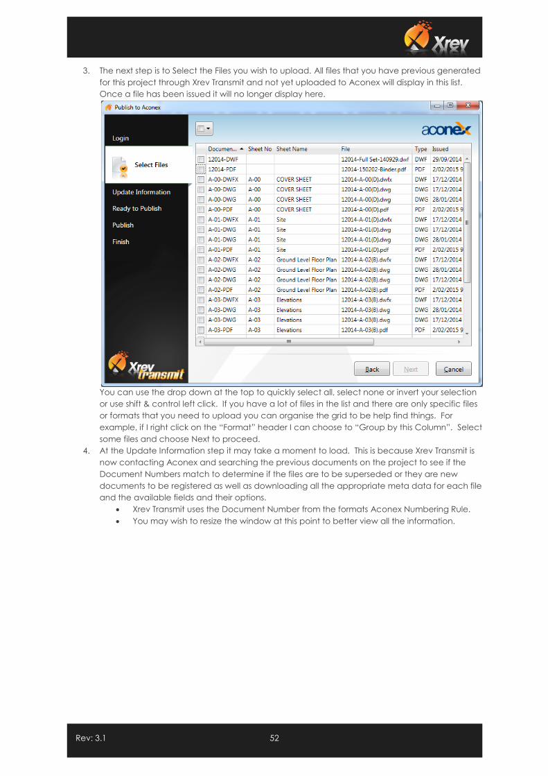
Rev: 3.1 52
3. The next step is to Select the Files you wish to upload. All files that you have previous generated
for this project through Xrev Transmit and not yet uploaded to Aconex will display in this list.
Once a file has been issued it will no longer display here.
You can use the drop down at the top to quickly select all, select none or invert your selection
or use shift & control left click. If you have a lot of files in the list and there are only specific files
or formats that you need to upload you can organise the grid to be help find things. For
example, if I right click on the “Format” header I can choose to “Group by this Column”. Select
some files and choose Next to proceed.
4. At the Update Information step it may take a moment to load. This is because Xrev Transmit is
now contacting Aconex and searching the previous documents on the project to see if the
Document Numbers match to determine if the files are to be superseded or they are new
documents to be registered as well as downloading all the appropriate meta data for each file
and the available fields and their options.
Xrev Transmit uses the Document Number from the formats Aconex Numbering Rule.
You may wish to resize the window at this point to better view all the information.
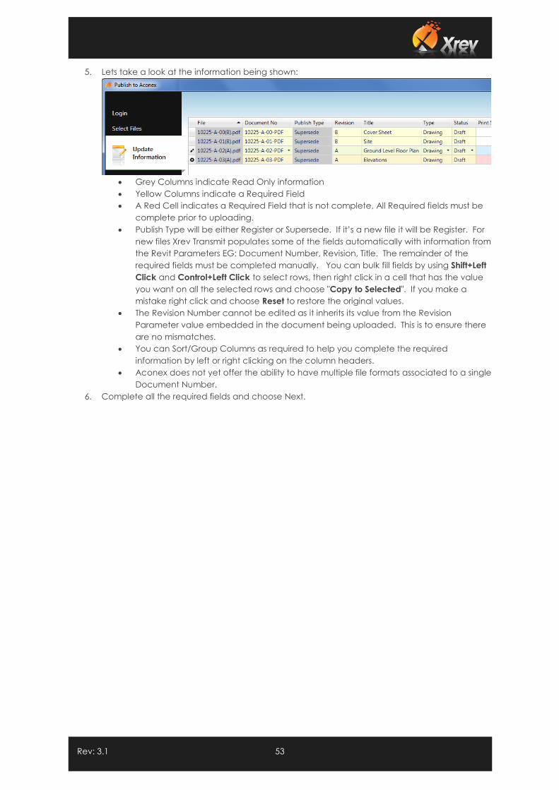
Rev: 3.1 53
5. Lets take a look at the information being shown:
Grey Columns indicate Read Only information
Yellow Columns indicate a Required Field
A Red Cell indicates a Required Field that is not complete, All Required fields must be
complete prior to uploading.
Publish Type will be either Register or Supersede. If it’s a new file it will be Register. For
new files Xrev Transmit populates some of the fields automatically with information from
the Revit Parameters EG: Document Number, Revision, Title. The remainder of the
required fields must be completed manually. You can bulk fill fields by using Shift+Left
Click and Control+Left Click to select rows, then right click in a cell that has the value
you want on all the selected rows and choose "Copy to Selected". If you make a
mistake right click and choose Reset to restore the original values.
The Revision Number cannot be edited as it inherits its value from the Revision
Parameter value embedded in the document being uploaded. This is to ensure there
are no mismatches.
You can Sort/Group Columns as required to help you complete the required
information by left or right clicking on the column headers.
Aconex does not yet offer the ability to have multiple file formats associated to a single
Document Number.
6. Complete all the required fields and choose Next.
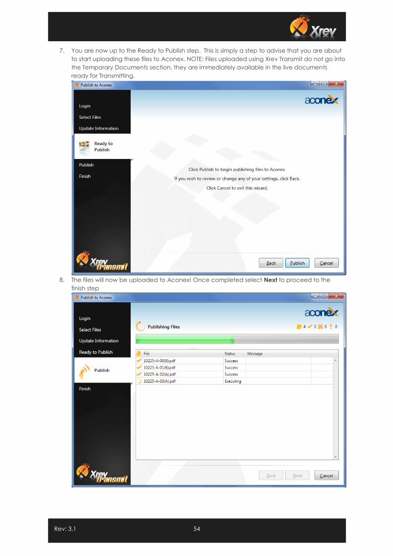
Rev: 3.1 54
7. You are now up to the Ready to Publish step. This is simply a step to advise that you are about
to start uploading these files to Aconex. NOTE: Files uploaded using Xrev Transmit do not go into
the Temporary Documents section, they are immediately available in the live documents
ready for Transmitting.
8. The files will now be uploaded to Aconex! Once completed select Next to proceed to the
finish step
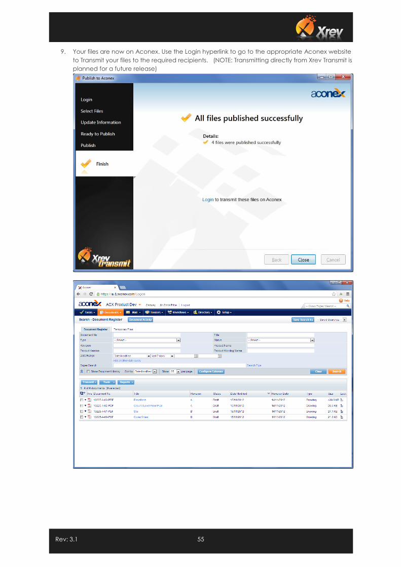
Rev: 3.1 55
9. Your files are now on Aconex. Use the Login hyperlink to go to the appropriate Aconex website
to Transmit your files to the required recipients. (NOTE: Transmitting directly from Xrev Transmit is
planned for a future release)
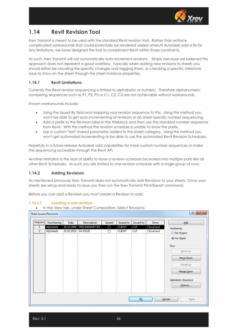
Rev: 3.1 56
1.14 Revit Revision Tool
Xrev Transmit is meant to be used with the standard Revit revision tool. Rather than enforce
complicated workarounds that could potentially be rendered useless when/if Autodesk add a fix for
any limitations, we have designed the tool to compliment Revit within those constraints.
As such, Xrev Transmit will not automatically auto-increment revisions. Simply because we believed this
approach does not represent a good workflow. Typically when adding new revisions to sheets you
should either be clouding the specific changes and tagging them, or checking a specific milestone
issue to show on the sheet through the sheet instance properties.
1.14.1 Revit Limitations
Currently the Revit revision sequencing is limited to alphabetic or numeric. Therefore alphanumeric
numbering sequences such as P1, P2, P3 or C1, C2, C3 are not achievable without workarounds.
Known workarounds include:
Using the Issued By field and mapping your revision sequence to this. Using this method you
won't be able to get auto-incrementing of revisions or do sheet specific number sequencing.
Add a prefix to the Revision label in the titleblock and then use the standard number sequence
from Revit. With this method the revision schedule is unable to show the prefix.
Use a custom "text" shared parameter added to the sheet category. Using this method you
won't get automated incrementing or be able to use the automated Revit Revision Schedules.
Hopefully in a future release Autodesk add capabilities for more custom number sequences or make
the sequencing accessible through the Revit API.
Another limitation is the lack of ability to have a revision schedule be broken into multiple parts like all
other Revit Schedules. As such you are limited to one revision schedule with a single group of rows.
1.14.2 Adding Revisions
As mentioned previously Xrev Transmit does not automatically add Revisions to your sheets. Once your
sheets are setup and ready to issue you then run the Xrev Transmit Print/Export command.
Before you can add a Revision you must create a Revision to add:
1.14.2.1 Creating a new revision
In the View tab, under Sheet Composition, Select Revisions.
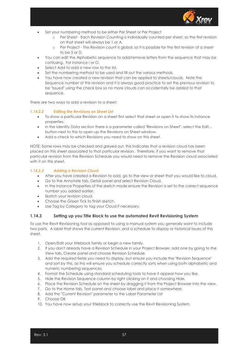
Rev: 3.1 57
Set your numbering method to be either Per Sheet or Per Project
o Per Sheet - Each Revision Counting is individually counted per sheet, so the first revision
on that sheet will always be 1 or A.
o Per Project - The Revision count is global, so it is possible for the first revision of a sheet
to be 3 or D.
You can edit the Alphabetic sequence to add/remove letters from the sequence that may be
confusing. For instance I or O.
Select Add to add a new row to the list.
Set the numbering method to be used and fill out the various methods.
You have now created a new revision that can be applied to sheets/clouds. Note the
Sequence number of this revision and it is always good practice to set the previous revision to
be "Issued" using the check box so no more clouds can accidentally be added to that
sequence.
There are two ways to add a revision to a sheet:
1.14.2.2 Editing the Revisions on Sheet List
To show a particular Revision on a sheet first select that sheet or open it to show its instance
properties.
In the Identity Data section there is a parameter called "Revisions on Sheet", select the Edit...
button next to this to open up the Revisions on Sheet window.
Add a check to which Revisions you need to show on this sheet.
NOTE: Some rows may be checked and greyed out, this indicates that a revision cloud has been
placed on this sheet associated to that particular revision. Therefore, if you want to remove that
particular revision from the Revision Schedule you would need to remove the Revision cloud associated
with it on this sheet.
1.14.2.3 Adding a Revision Cloud
After you have created a Revision to add, go to the view or sheet that you would like to cloud.
Go to the Annotate tab, Detail panel and select Revision Cloud.
In the Instance Properties of the sketch mode ensure the Revision is set to the correct sequence
number you added earlier.
Sketch your revision cloud.
Choose the Green Tick to finish sketch.
Use Tag by Category to tag your Cloud if necessary.
1.14.3 Setting up you Title Block to use the automated Revit Revisioning System
To use the Revit Revisioning tool as opposed to using a manual system you generally want to include
two parts. A label that shows the current Revision, and a schedule to display or historical issues of this
sheet.
1. Open/Edit your titleblock family or begin a new family.
2. If you don't already have a Revision Schedule in your Project Browser, add one by going to the
View tab, Create panel and choose Revision Schedule.
3. Add the required fields you need to display, but ensure you include the "Revision Sequence"
and sort by this, as this will ensure you schedule correctly sorts when using both alphabetic and
numeric numbering sequences.
4. Format the Schedule using standard scheduling tools to have it appear how you like.
5. Hide the Revision Sequence column by right clicking on it and choosing Hide.
6. Place the Revision Schedule on the sheet by dragging it from the Project Browser into the view.
7. Go to the Home tab, Text panel and choose label and place it somewhere.
8. Add the "Current Revision" parameter to the Label Parameter List
9. Choose OK
10. You have now setup your titleblock to correctly use the Revit Revisioning System.
Rev: 3.1 58
1.15 Troubleshooting
Please report any errors/problems you have to our support team at [email protected] and we will
address it as a priority.
1.15.1 Activation Fails
1.15.1.1 Applicable to:
Revit 2011 & Revit 2012, with locked down networks through Firewalls / Proxy Servers
1.15.1.2 Issue/Problem:
When attempting to activate Xrev Transmit the activation fails.
1.15.1.3 Reason:
To activate Xrev Transmit needs to contact our License server over HTTP or HTTPS. If this is filtered or
blocked your computer may not be able to access this server.
1.15.1.4 Resolution Required:
You can try temporarily removing the Proxy setting in Internet Explorer to bypass the proxy server and try
activation as this may resolve the issue or add licence.xrev.com.au to your whitelist. Alternatively there
is a manual activation process in the Licensing part of Xrev Transmit which requires you to manually
send us the Machine code (that Xrev Transmit generates) and the serial number. We will then supply
an activation code for each machine that is unable to activate.