Embed Size (px)
Citation preview

Stanford Synchrotron Radiation Laboratory
X-ray DiffractionMike Toney
Stanford Synchrotron Radiation Laboratory
1. Crystals and crystal geometry (planes)2. Bragg’s law3. Reciprocal lattice & reciprocal space
• definition and examples• relation to diffraction
4. Diffraction intensities and crystallography5. Some examples from current research
• Macromolecular Crystallography• Powder Diffraction – Zeolites• Strain: Eu films• Pentacene films
Outline
• B Warren, “X-ray Diffraction”, Dover (1990): $11.87 & Eligible for FREE Super Saver Shipping on amazon.com.
• BD Cullity & SR Stock, “X-ray Diffraction”, Prentice Hall (2001).
• J Als-Nielsen & D McMorrow, “Elements of Modern X-ray Physics”, Wiley (2001).
Bibliography

Diffraction vs Scattering
0 20 40 60 80
1000
2000
3000
4000
5000
6000
7000
21 24 27
2000
4000
6000
Inte
nsity
2θInte
nsity
2θ
diffraction: Bragg peaks
scattering: the rest

Crystal Lattice
Crystal lattice: periodic, repeating arrayLattice point – atom, molecule, or fixed arrangement of atoms, or protein, fullerene, …
Lattice Vectors span the unit cellunit cell

Crystal Lattice
a0

Crystal Planes
plane spacings (d):
(100): d = a0
(110): d = a0/√2
(111): d = a0/√3
(hkl): d= a0/√h2 + k2 + l2
a0
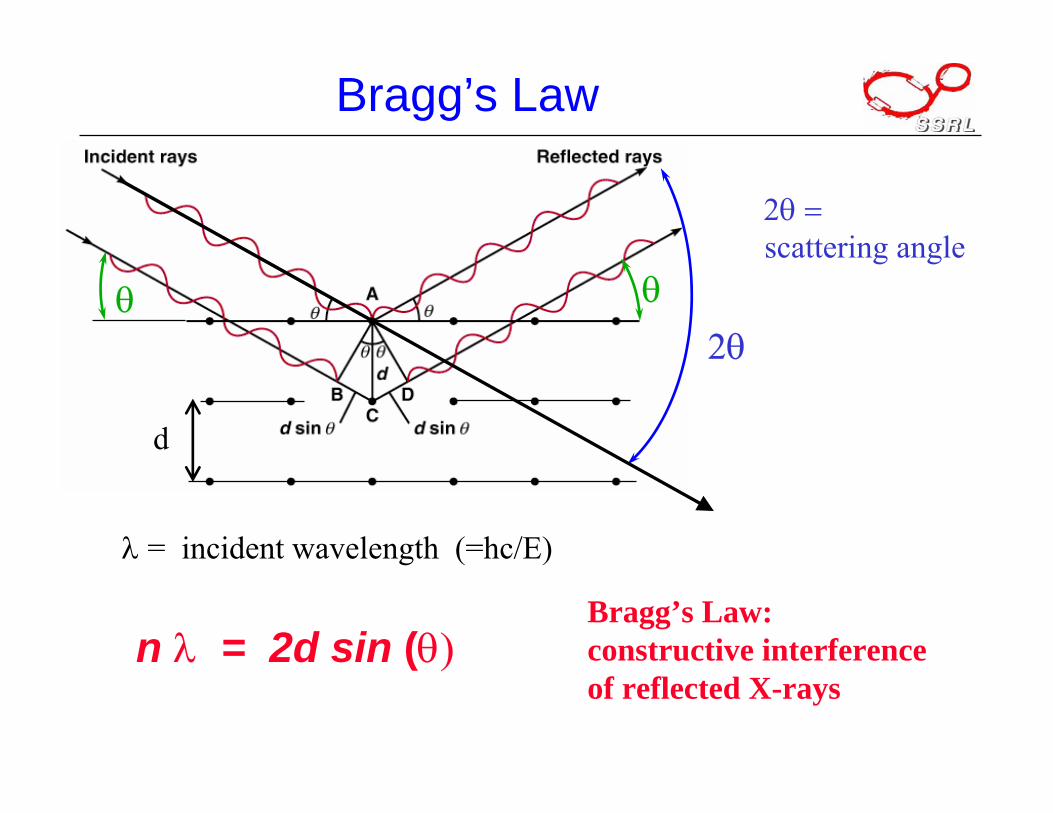
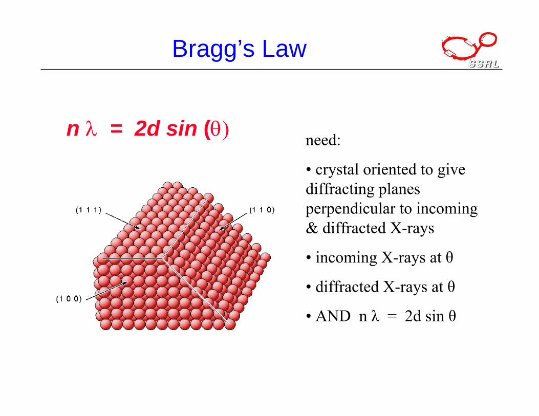
Bragg’s Law
n λ = 2d sin (θ)
λ = incident wavelength (=hc/E)
d
θ
Bragg’s Law: constructive interference of reflected X-rays
θ
2θ = scattering angle
2θ
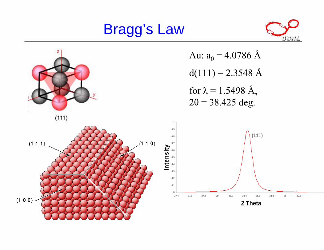
Bragg’s LawAu: a0 = 4.0786 Å
d(111) = 2.3548 Å
for λ = 1.5498 Å, 2θ = 38.425 deg.
0
0.1
0.2
0.3
0.4
0.5
0.6
0.7
0.8
0.9
1
37.4 37.6 37.8 38 38.2 38.4 38.6 38.8 39 39.2
2 Theta
Inte
nsity
(111)
Bragg’s Law
need:
• crystal oriented to give diffracting planes perpendicular to incoming & diffracted X-rays
• incoming X-rays at θ
• diffracted X-rays at θ
• AND n λ = 2d sin θ
n λ = 2d sin (θ)
Reciprocal Lattice
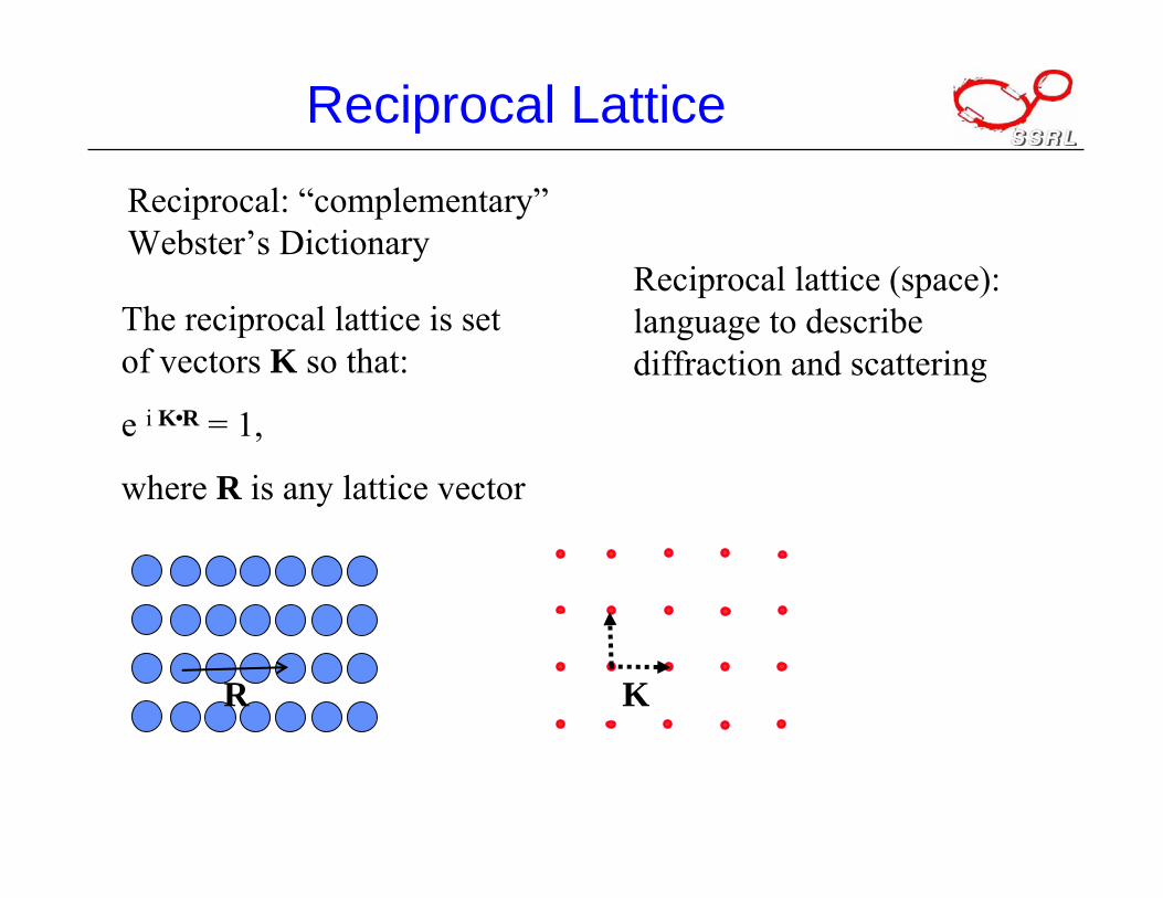
Reciprocal: “complementary”Webster’s Dictionary
Reciprocal lattice (space): language to describe diffraction and scattering
R K
The reciprocal lattice is set of vectors K so that:
e i K R = 1,
where R is any lattice vector

Reciprocal Lattice
a0
a* = 2π/a0
b* = 2π/a0
(-20) = (2 0)
e i K R = 1,
where R is any lattice vector
(20)(00) (10)
(01)
(-20)
(02)
a*
b*

Reciprocal Lattice
(20)(00) (10)
(0-1)
(0-2)
G1 or a*
G2 or b*
G1 d1 = 2π
G2 d2 = 2π

Reciprocal Lattice
(110)
(000) (100)
(111)
a0
real space:simple cubic
2π/a0
reciprocal space:simple cubic
e i K R = 1,
where R is any lattice vector

Reciprocal Lattice & Diffraction
Q
sample
kin kout
Q = scattering vector= kin – kout
• Constructive interference of X-rays (diffraction peaks) requires that e i Q R = 1.
• So Q = K, where K is a reciprocal lattice vector
(2 0)(-1 1)
(-1-1)
(1 1)
(1 -1)
(-2 0)
Q

Reciprocal Lattice
Stringent condition!
• Rotating crystal (macromolecular crystallography)
• Powder diffraction
• Live with it (single crystal)
(2 0)(11), (1-1)
(2 0)(-1 1)
(-1-1)
(1 1)
(1 -1)
(-2 0)
Q
Diffraction: Q = K
Diffraction Intensities
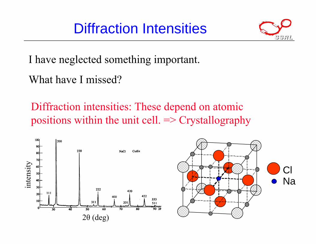
I have neglected something important.
What have I missed?
Diffraction intensities: These depend on atomic positions within the unit cell. => Crystallography
ClNa
2θ (deg)
inte
nsity

Diffraction Intensities
This can be reduced to:
where
and h,k,l are peak indices.
F = fn e 2 π i( ) hx n + ky n + lz n( )
n∑
r r n = xn + yn + zn( )
The structure factor, F, is defined as:
where fn is the atomic scattering factor;
is the position of the nth atom in the unit cell. r r n
nrQi
nnefF
rr⋅∑=
Intensity = |F|2
Phase problem
Explain better & show x, y, z and h k l

Diffraction IntensitiesF = fn e 2 π i( ) hx n + ky n + lz n( )
n∑
Simple cubic lattice:(x, y, z) = (0, 0, 0) => F = fn
bcc lattice:(x, y, z) = (0, 0, 0) & (½, ½, ½)⇒ F = fn {1 + eiπ(h+k+l)}⇒ F = 2 fn for h+k+l = even
= 0 otherwise

Diffraction Intensities
fcc lattice:(x, y, z) = (0, 0, 0), (½, ½, 0), (½, 0, ½) & (0, ½, ½)⇒ F = fn {1 + eiπ(h+k) + eiπ(h+l) + eiπ(k+l)}⇒ F = 4fn: h,k,l all even or odd
= 0, otherwise

Polyatomic Crystal: Rock Salt
ClNa
like fcc lattice:Na at (0, 0, 0)Cl at (½, 0, 0)⇒ F = {fNa + eiπh fCl}Ffcc
⇒ F = 4{fNa+ fCl}Ffcc: h,k,l even= 4{fNa- fCl}Ffcc: h,k,l odd= 0, otherwise

Macromolecular Crystallography
Macromolecule = big molecule, mostly biological.
Protein, virus, vitamins, …
Molecular structure determines function, how it works
astaxanthinpigment
= oxygen= carbon= hydrogen
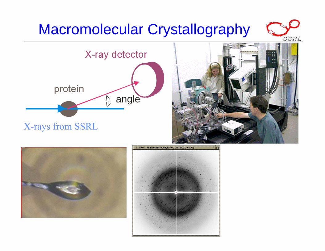
Macromolecular Crystallography
angle
X-rays from SSRL

Vitamin B12
Dorothy Hodgkin (1910-1994)Nobel Prize, 1964
Vitamin B12Solved in 1956

Powder Diffraction
“Powder” average by random orientation of crystals
Problems due to peak overlap

Powder Diffraction
SSRL 2-1:
Dedicated for powder diffraction
incident x-rays
diffracted x-rays
sample

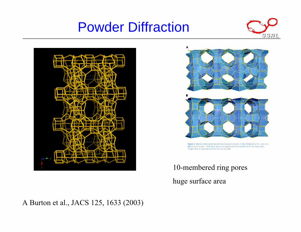
Powder Diffraction: Zeolites
Zeolites: microporousaluminosilicates used as catalysis, adsorbents, ….
Rare single crystals
A Burton et al., JACS 125, 1633 (2003)
SSZ-58: novel zeolitedeveloped by Chevron-Texaco Research
SSZ-58 structure ‘solved’with advanced ab initiomethods
Powder Diffraction
A Burton et al., JACS 125, 1633 (2003)
10-membered ring pores
huge surface area

Diffraction Measurements of Strain
Many materials properties depend on strain: magnetostriction, mobility, pizeoelectricity
X-ray diffraction provides a very accurate & precise method of strain measurement
Q = (4π/λ) sin θtypical 2θ resolution is 0.001-0.1 deggives Q resolution of 0.0001-0.01 Å-1
translates to d resolution of 0.005-0.00005 Å(0.5-0.005 pm)
0
0.1
0.2
0.3
0.4
0.5
0.6
0.7
0.8
0.9
1
37.4 37.6 37.8 38 38.2 38.4 38.6 38.8 39 39.2
2 Theta
Inte
nsity
Symmetric
Asymmetric
∆ 2θ = 0.03 deg

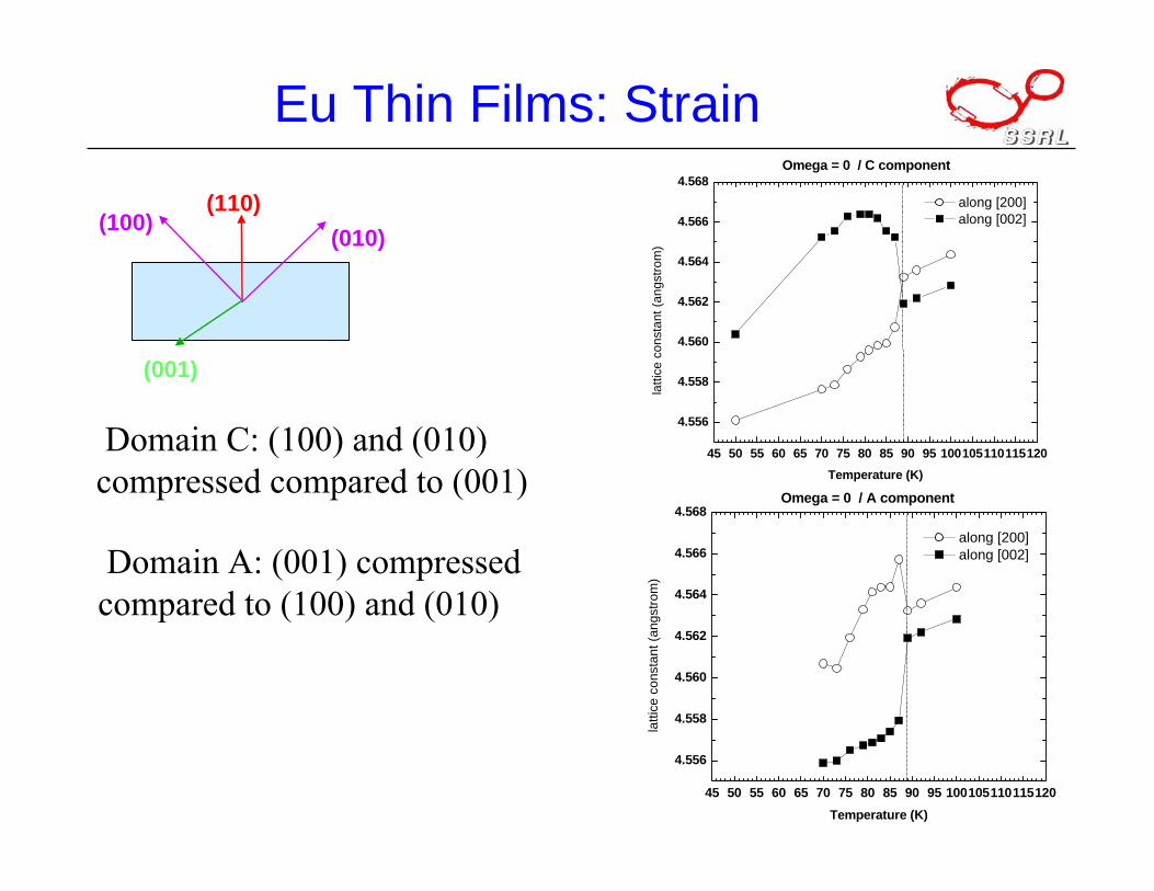
Eu Thin Films: Strain
S. Soriano, K. Dumesnil, C. Dufour, T. Gourieux, A.Stunault, M. Hennion, J.A. Borchers, Ph.Mangin, Laboratoire de Physique des Matériaux (LPM) – Nancy, Intitut Laue Langevin (ILL) – ESRF - Grenoble,Laboratoire Leon Brillouin (LLB) (Saclay), NIST Center for Neutron Research (NCNR)
15nm (110)Nb 150°C
Y
(1120) Al2O3
50nm (110)Nb 800°C
(110)Eu 150°C
Molecular beam epitaxy (4.10-11 Torr)
Bulk Eu: bcc
TN = 90K
Para.
[001]
[100]
[010](110)
Eu(110)
(100) (010)
(001)

• Disappearance of one of the magnetic helices (τ//[001]) in favor of the two others: τ//[100] and τ//[010]
• Thermal hysteresis
375 nm thick filmsM
agne
tic p
opul
atio
ns
Temperature (K)0 10 20 30 40 50 60 70 80 90
0,0
0,1
0,2
0,3
0,4
0,5
0,6
(100)(010)(001)
RXMSESRF - BM28
Eu L2 edge
Magnetic State of Eu Thin Films
(110)
(100)(010)
(001)

• a⊥ = a(110): match bulk 300K-10K
• a//= a(002) =a(110):- match bulk T>Tcl- for T<Tcl constant to 10 K
• Tcl depends on the film thickness
• The amplitude of the strains increase with decreasing temperature and reduced film thickness.
0 50 100 150 200 250 300
4,54
4,55
4,56
4,57
4,58
4,59
750 nm
375 nm
75 nm
Temperature (K)
latt
ice
para
met
er (a
ngst
rom
)Eu Thin Films: Lattice Clamping
a (110)
a(001) & a(110)
neutron diffraction data

Eu Thin Films: Strain
Karine Dumesnil, UniversitéH. Poincaré - Nancy, France on SSRL beam line 7-2
15nm (110)Nb 150°C
Y
(1120) Al2O3
50nm (110)Nb 800°C
(110)Eu 150°C
• Use diffraction to accurately assess strain state
• Depth dependent strain

Eu Thin Films: Strain
8.22 8.23 8.24 8.25 8.26 8.27 8.28 8.290
5
10
15
20
25
30
35
40
87.5K
70K
88K
88.5K
Inte
nsity
(cts
/mon
)
(116)
8.22 8.23 8.24 8.25 8.26 8.27 8.28 8.290
5
10
15
20
25
30
35
40
45
50
(116)Decrease in T
Inte
nsity
(cts
/mon
)
89K 87K 85K 83K 81K 79K 76K 73K 70K
Q along (001) ( Å-1)
decreasing temperature
(110)(116)
(001)
Q along (001) ( Å-1)
Eu=> two domains with different strain states
45 50 55 60 65 70 75 80 85 90 95 100105110115120
4.556
4.558
4.560
4.562
4.564
4.566
4.568Omega = 0 / C component
along [200] along [002]
latti
ce c
onst
ant (
angs
trom
)
Temperature (K)
45 50 55 60 65 70 75 80 85 90 95 100105110115120
4.556
4.558
4.560
4.562
4.564
4.566
4.568Omega = 0 / A component
along [200] along [002]
latti
ce c
onst
ant (
angs
trom
)
Temperature (K)
Eu Thin Films: Strain
Domain A: (001) compressed compared to (100) and (010)
(110)
(001)
(100) (010)
Domain C: (100) and (010) compressed compared to (001)

Organic Thin Films
Organic FETSandra Fritz,C. Daniel Frisbie,Mike Ward,Chemical Engineering and Materials ScienceUniversity of Minnesota

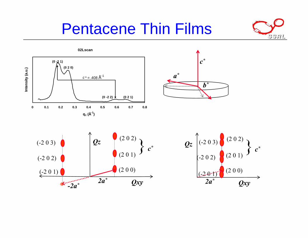
Pentacene Thin Films
2 7 12 17 222theta (degrees)
Inte
nsity
(arb
itrar
y un
its)
“thin film” phase, d001 = 15.4Å-rocking curve width >0.05o
=> highly textured films
“bulk” phase, d001 = 14.4Å
• Thermal evaporation of pentacene
• Film morphology and structure dependant on substrate temperature, deposition rate and film thickness
1.5 nm - one layer
30 nm – ca 15 layers
5 µm
5 µm
300 nm SiO2
Si
1.5 – 60 nm pentacene
θ/2θ XRD: ca 50 nm film

Grazing Incidence Diffraction
2θα
β
2θ is scattering angleQ = scattering vectorQ = k’ - kQ = (4π/λ) sin θα = incidence angleβ = exit angle
SiO2
pentacene
Vary penetration depth by changing incidence angle α
Needs good collimation
300 nm SiO2
Si
pentacene

Pentacene Thin Films
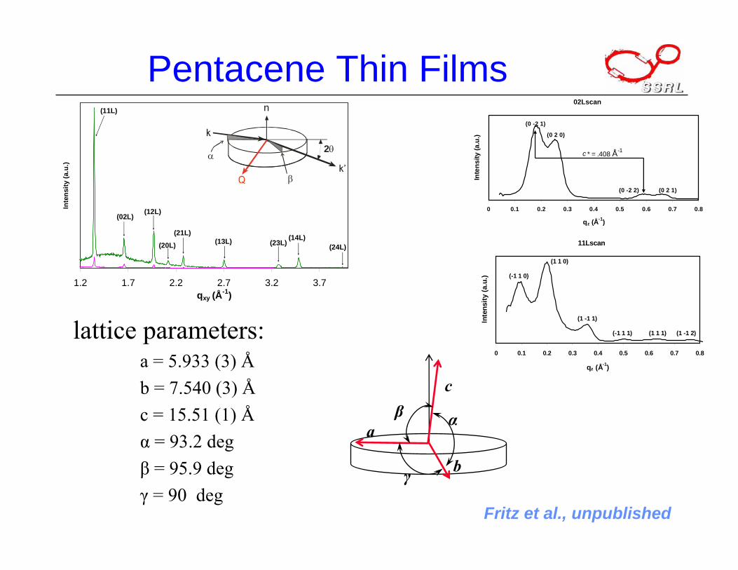
1.2 1.7 2.2 2.7 3.2 3.7qxy (Å-1)
Inte
nsity
(a.u
.)
monolayer200 Å
(11L)
(02L)(12L)
(20L)
(21L)
(24L)(14L)
(23L)(13L)
2θα
β
b*
c*
a*
(-2 0)
Qz
Qxy
(-2 0 0)
(-2 0 1)
(-2 0 2)
} c*
Qxy
(2 0)(-1 1)
(-1-1)
(1 1)
(1 -1)
Fritz et al., unpublished
Pentacene Thin Films
} c*Qz
Qxy
(2 0 0)
(2 0 1)
(2 0 2)
b*
c*
a*
(-2 0 1)
(-2 0 2)
(-2 0 3)
2a*-2a*
02Lscan
0 0.1 0.2 0.3 0.4 0.5 0.6 0.7 0.8
qz (Å-1)
Inte
nsity
(a.u
.)
c * = .408 Å-1
(0 -2 1)
(0 2 0)
(0 -2 2) (0 2 1)
} c*Qz
Qxy
(2 0 0)
(2 0 1)
(2 0 2)
(-2 0 1)
(-2 0 2)
(-2 0 3)
2a*

Pentacene Thin Films
b*
c*
a*
11Lscan
0 0.1 0.2 0.3 0.4 0.5 0.6 0.7 0.8
qz (Å-1)
Inte
nsity
(a.u
.)
(1 1 0)
(-1 1 0)
(1 -1 1)
(-1 1 1) (1 1 1) (1 -1 2)
Qz
Qxy
(1-1 0)
(1-1 1)
(1-1 2)
(-11 1)
(-11 2)
(-11 3)
-a* + b*a* - b*
} c*Qz
Qxy
(1 1 0)
(1 1 1)
(1 1 2)
(-1-11)
(-1-12)
(-1-13)
-a* - b* a* + b*
|a* +/- b* |
Qz
Qxy
(11 0)
(-11 1)(1-1 1)
(-11 0)
02Lscan
0 0.1 0.2 0.3 0.4 0.5 0.6 0.7 0.8
qz (Å-1)
Inte
nsity
(a.u
.)
c * = .408 Å-1
(0 -2 1)
(0 2 0)
(0 -2 2) (0 2 1)
Pentacene Thin Films
1.2 1.7 2.2 2.7 3.2 3.7qxy (Å-1)
Inte
nsity
(a.u
.)
monolayer200 Å
(11L)
(02L)(12L)
(20L)
(21L)
(24L)(14L)
(23L)(13L)
2θα
β
lattice parameters:a = 5.933 (3) Åb = 7.540 (3) Åc = 15.51 (1) Åα = 93.2 degβ = 95.9 degγ = 90 deg
b
c
a
11Lscan
0 0.1 0.2 0.3 0.4 0.5 0.6 0.7 0.8
qz (Å-1)
Inte
nsity
(a.u
.)
(1 1 0)
(-1 1 0)
(1 -1 1)
(-1 1 1) (1 1 1) (1 -1 2)
Fritz et al., unpublished
β α
γ

• Pentacene thin films on SiO2 are crystalline, but distinct from bulk
• Thin Film: herringbone motif with molecules tilted a few-ten degrees
5µm
a
bγ
Fritz et al., unpublished
Pentacene Thin Films
Summary
Crystals and geometryBragg’s lawReciprocal lattice & reciprocal space• definition and examples• relation to diffractionDiffraction intensities and crystallographyFew Examples• Molecular & Crystal structure• Strain