Embed Size (px)
Citation preview

McIntosh Laboratory, Inc. 2 Chambers Street Binghamton, New York 13903-2699 Phone: 607-723-3512 www.mcintoshlabs.com
XR50
Loudspeaker System
Owner’s Manual

2
1. Read these instructions.2. Keep these instructions.3. Heed all warnings.4. Follow all instructions.5. Do not use this apparatus near water.6. Clean only with a non-abrasive dry soft cloth.7. Install in accordance with the manufacturer’s
instructions.8. This Loudspeaker is capable of producing
extremely high sound pressure levels, even when connected to amplifiers of moderate power output. User caution is advised. Ear protection is recommended when playing at high volumes as continued exposure to high sound pressure levels can cause permanent hearing impairment or loss. The use of a Sound Level Pressure Meter will greatly aid in determining when high volume levels are occurring.
9. Do not install near any heat sources such as radiators, heat registers, stoves, or other apparatus (including amplifiers) that produce heat.
10. Only use attachments/accessories specified by the manufacturer.
11. Use only with the cart, stand, tripod, bracket, or table specif ied by the manufacturer, or sold with the apparatus. When a cart is used, use caution when moving the cart/apparatus combination to avoid injury from tip-over.
12. Refer all servicing to qualified service personnel. Servicing is required when the apparatus has been damaged in any way, liquid has been spilled or objects have fallen into the apparatus, the apparatus has been exposed to rain or moisture, does not operate normally, or has been dropped.
WARNING - TO REDUCE RISK OF FIRE OR ELECTRICAL SHOCK, DO NOT EXPOSE THIS EQUIPMENT TO
RAIN OR MOISTURE.
NO USER-SERVICEABLE PARTS INSIDE. REFER SERVICING TO
QUALIFIED PERSONNEL.To prevent the risk of electric shock, do not remove cover or
back. No user-serviceable parts inside.
IMPORTANT SAFETYINSTRUCTIONS!
PLEASE READ THEM BEFOREOPERATING THIS EQUIPMENT.
13. Do not expose this equipment to dripping or splashing and ensure that no objects filled with liquids, such as vases, are placed on the equipment.
14. WARNING: When this Loudspeaker is connected to an amplifier that is Powered On, the connection terminals may have hazardous live voltages present with a risk of electric shock.

3
1. For additional connection information, refer to the owner’s manual(s) for any component(s) connected to the XR50 Loudspeaker.
2. The design of XR50 Loudspeaker took into ac-count the acoustic characteristics of the Front Panel
Your decision to own this McIntosh XR50 Loudspeak-er System ranks you at the very top among discrimi-nating music listeners.. You now have “The Best.” The McIntosh dedication to “Quality,” is assurance that you will receive many years of listening enjoyment from this unit.Please take a short time to read the information in this manual. We want you to be as familiar as pos-sible with all the features and functions of your new McIntosh.
Safety Instructions .................................................... 2Thank You and Please Take a Moment ..................... 3Technical Assistance and Customer Service ............ 3Table of Contents and General Information ............. 3Connector/Cable Information ................................... 3Introduction ............................................................... 4Performance Features ............................................... 5Dimensions ............................................................6-7Unpacking the Loudspeaker ..................................... 8Installation .............................................................8-9How to Connect ................................................. 10-11Photos ................................................................. 12-13Specifications .......................................................... 14Packing Instruction ................................................. 15
Table of Contents
Thank You
Please Take A Moment
Technical AssistanceIf at any time you have questions about your McIntosh product, contact your McIntosh Dealer who is familiar with your McIntosh equipment and any other brands that may be part of your system. If you or your Dealer wish additional help concerning a suspected problem, you can receive technical assistance for all McIntosh products at:
McIntosh Laboratory, Inc.2 Chambers StreetBinghamton, New York 13903Phone: 607-723-3512Fax: 607-724-0549
Customer ServiceIf it is determined that your McIntosh product is in need of repair, you can return it to your Dealer. You can also return it to the McIntosh Laboratory Service Department. For assistance on factory repair return procedure, contact the McIntosh Service Department at:
McIntosh Laboratory, Inc.2 Chambers StreetBinghamton, New York 13903Phone: 607-723-3515Fax: 607-723-1917
The serial number, purchase date and McIntosh Dealer name are important to you for possible insurance claim or future service. The spaces below have been provided for you to record that information:
Serial Number: _______________________________
Purchase Date: _______________________________
Dealer Name: ________________________________
Copyright 2011 © by McIntosh Laboratory, Inc.
General Information
Power Control ConnectorsThe XR50 Power Control Jacks (IN/OUT) receive and pass on an ON/OFF signal from +5 to +12 volts. An additional connection passes on Meter Illumination Control for compatible Power Amplifiers. The 1/8 inch stereo mini phone plug connects to a McIntosh Preamplifier or A/V Control Center Power Control Output.
Connector/Cable Information
PowerControl
Ground
MeterIlluminationControlPass Thru
Grille and it should be attached to the Loudspeaker for the best sonic performance.
3. If there is an obvious lack of high, mid or low frequencies after extended periods of overdrive, the Protection Device(s) may have activated. These devices will automatically reset when the volume level is greatly reduced until the output of the af-fected Loudspeaker Driver(s) returns to normal.
4. When discarding the unit, comply with local rules or regulations. Batteries should never be thrown away or incinerated but disposed of in accordance with the local regulations concerning battery disposal.
5. For additional information on the XR50 and other McIntosh Products please visit the McIn-tosh Web Site at www.mcintoshlabs.com.

4
McIntosh Acoustic Engineers have achieved in the de-sign of the XR50 Loudspeaker System, a level of high performance. The XR50 provides superior spacious-ness sound reproduction with unusual sound stage depth in a full range system.
The XR50 utilizes a three-quarter inch Titanium Dome Tweeter and 2 two inch Midrange Inverted Titanium Dome Drivers. Refer to figures 1 and 2. Since the audio power is distributed among all the drivers, each driver does not have to work as hard, resulting in greater power handling capability, dra-matic reduction in distortion and greater dynamic range.
The Low Frequency Section of the System consists of a newly designed six inch Woofer. Refer to figure 3.
The Woofer incorporates McIntosh’s Patented LD/HP® 1 Magnetic Circuit Design. Finite Element Analy-sis and testing resulted in a design concept which utilizes a pair of aluminum shorting sleeves in the magnetic circuit. Refer to figure 4. The sleeves greatly reduce the nega-tive influence of the fluc-tuating voice coil field on the permanent magnet field. This results in lower distortion due to more linear magnetic flux in the voice coil gap. Refer to figure 5. Additional benefits are less volume compres-sion due to improved heat trans-fer through the sleeves and a cooler operating voice coil. Both measurements, as well as critical listening, reveal ten times less distortion than previ-ous designs. A good example of this low distortion is incredible smoothness and clarity in the reproduction of the human voice.
The Crossover Network used in the XR50 Loud-speaker System is designed to ensure an even fre-quency response over the entire audible range. The Second Order Designed Network utilizes Capacitors and Inductors with high current capacity. Refer to fig-
ure 6. The XR50 uses low loss (DCR) Inductors in the crossover network. The type of Inductor used in each section of the crossover network has been chosen for high linearity, even at high power levels. This prevents distortion of the music at any frequency. The Capaci-tors used are the low loss (ESR) types. The Network also utilizes self resetting high current PTC Fuses to provide an extra measure of protection.
The enclosure is an important part of the XR50 Loudspeaker System. It has a front to back and side to side internal brace to form a dampened rigid Loud-speaker enclosure. The Loudspeaker’s small footprint allows for a variety of different placements in a room.
Introduction
Figure 6
Figure 1
Figure 2
Figure 3
Figure 5
Figure 4
LD/HP
Conventional
1LD/HP Pat. No 5,151,943

5
Connector/Cable Information, Introduction and Performance Features
Performance Features• Patented LD/HP® TechnologyThe McIntosh Low Frequency Loudspeaker Elements feature the patented LD/HP Magnetic Circuit Design. This design, when compared to conventional Loud-speaker Drivers, reduces distortion significantly. It also increases power handling and efficiency.
The rear vent through the magnetic assembly offers improved heat dissipation. The die cast basket has an open air area under the voice coil/spider assembly to prevent displacement noise. The polypropylene cone with a rubber surround has a four layer copper voice coil and is rigid to perform as a near perfect air piston.
Altogether these advances in woofer design con-struction and materials produce the very important first several octaves of music, with a high degree of accuracy and superb transient response. This perfor-mance level rivals woofers twice the size of the XR50 woofer.
• Neodymium-Iron-Boron Alloy MagnetsThe two inch Midranges and three-quarter inch Dome Super Tweeter all use this Alloy. The Neodymium-Iron-Boron Alloy has the highest flux density per unit of volume. This allows for a smaller physical size driver and thus closer driver to driver placement for improved dispersion.
• Low Harmonic and Intermodulation DistortionThe XR50 Loudspeaker System is capable of repro-ducing the full dynamic range of a symphony orches-tra with very low audible distortion of any kind.
• Low Frequency PortThe XR50 Loudspeaker System utilizes a vertical port with a rear opening to increase bass output, reduce distortion and improve the overall efficiency of the Loudspeaker.
• High Power HandlingThe Loudspeaker Elements and Crossover Compo-nents of the XR50 are all chosen for use with ampli-fiers up to 300 watts, yet can be driven with a 75 watt amplifier.
• Superior ImagingLocating the Super Tweeter between the two Midrang-es generates a symmetrical polar response for superior imaging.
• Loudspeaker EnclosureThe XR50 Loudspeaker enclosure is constructed with non-parallel internal sides to reduce internal standing waves and is available in various finishes.
• McIntosh Custom Binding PostsMcIntosh patent pending gold plated input terminals accept high current signals. They accept large diam-eter wire and spade lugs. Banana plugs may also be used.
• Power ControlThe Power Control Input supplies power to illuminate the XR50 McIntosh Logo and Power Control Output supplies power for remote turn-on of additional Com-ponents.
• Solid State Front Panel Logo IlluminationThe even Illumination of the Front Panel Logo is ac-complished by the combination of custom designed Light Diffusers and extra long life Light Emitting Diodes (LEDs).

6
DimensionsThe following dimensions can assist in determining the best location for your XR50.
Front View of the XR50
Loudspeaker System
Rear View ofthe XR50
Loudspeaker System
Side View ofthe XR50
Loudspeaker System
17" 43.0cm
8" 20.3cm 9-7/8"
25.0cm
7/8" 2.2cm
16-1/2" 42.0cm
12-5/8" 32.0cm
5-1/2"13.8cm
5/8"1.8cm
2"5.1cm
4"10.2cm
6"15.2cm
6-1/2"16.5cm
11-3/4"29.9cm
7
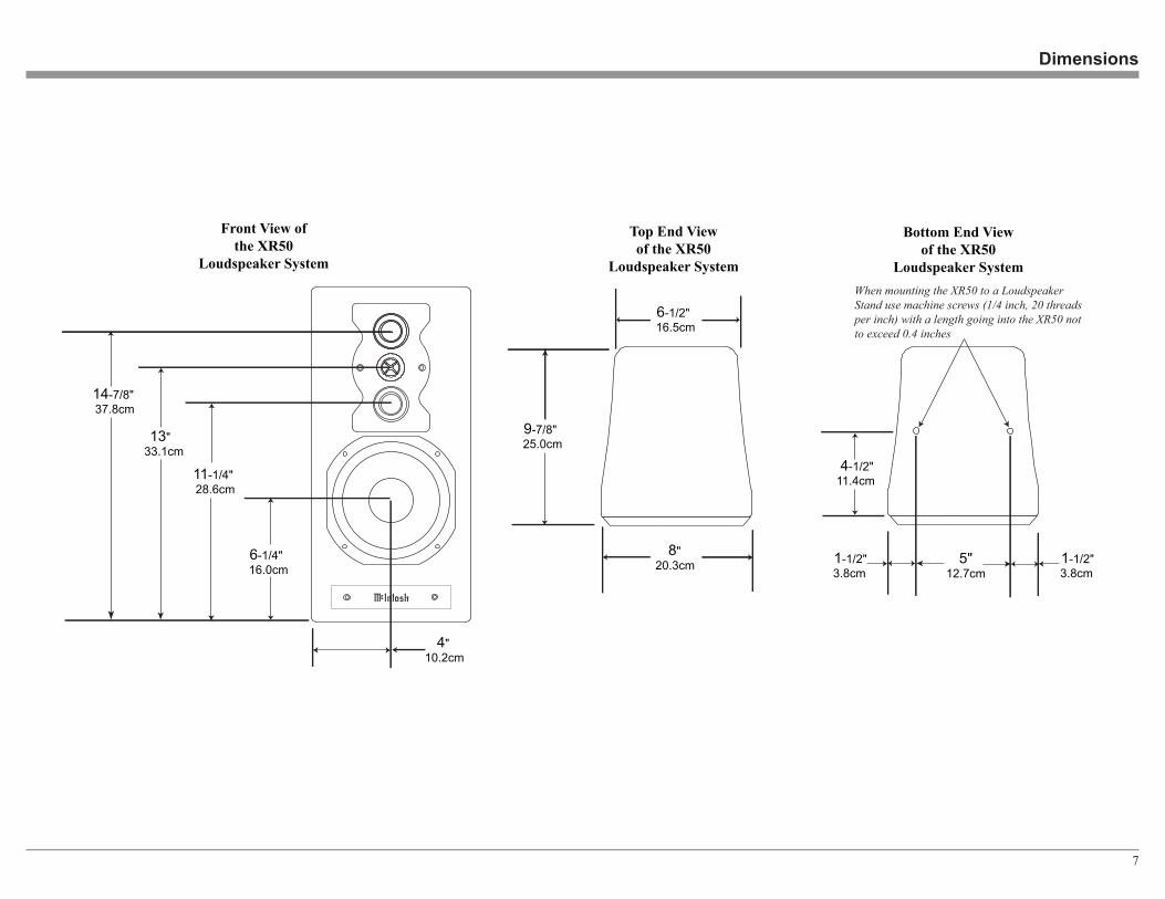
Dimensions
Front View ofthe XR50
Loudspeaker System
Top End Viewof the XR50
Loudspeaker System
8" 20.3cm
9-7/8" 25.0cm
6-1/2" 16.5cm
4"10.2cm
6-1/4" 16.0cm
11-1/4" 28.6cm
13" 33.1cm
14-7/8" 37.8cm
Bottom End Viewof the XR50
Loudspeaker System
4-1/2"11.4cm
5" 12.7cm
1-1/2" 3.8cm
When mounting the XR50 to a LoudspeakerStand use machine screws (1/4 inch, 20 threadsper inch) with a length going into the XR50 notto exceed 0.4 inches
1-1/2" 3.8cm

8
Loudspeaker PlacementLoudspeaker placement in a room can greatly affect performance. The XR50 Loudspeaker is designed for both Music and Home Theater Systems. The optimal method for selecting speaker locations includes the use of a real time spectrum analyzer operated by an experienced system installer. An uncompromising installation would take into consideration the floor, wall and ceiling coverings, the type and placement of furniture and can even include the architectural design of the room and its construction materials. In those instances where placement in the room is fixed, an en-viromental equalizer may be needed to restore proper musical balance.
Placement near a wall, corner, floor, ceiling or any intersecting surfaces will reinforce or diminish some bass frequencies. The bass frequencies that are altered by placement in a particular location is dependent on the dimensions of the room. If professional measure-ment equipment is not available, listen to the Loud-speaker. Try various locations by listening to music containing continuous bass and finding a location where there is an over all musical balance in the sound and the bass content does not dominate.
The XR50’s Smooth Frequency Response may be altered by a large object(s) located in the sound waves path or by locating the Loudspeaker too close to a side wall. There should be an unobstructed area in front of the Loudspeaker of at least 30 degrees either side from the center axis for the best performance. Refer to figure 8.
Installation
Figure 8
Unpacking the LoudspeakerTo protect the fine finish of the XR50 Loudspeaker System during the installation process, it is advisable to prepare a suitable area. A freshly vacuumed car-peted area covered with a soft, clean fabric, such as a large bed linen or blanket would be suitable.
It is recommended that the Professionals at your McIntosh Dealer, who are skilled in all aspects of in-stallation and operation, install the XR50 Loudspeaker System and any associated audio equipment.
1. Remove the top foam cap from the shipping car-ton.
2. Remove the inner carton containing the Loud-speaker Grille.
3.Remove the Loudspeaker System by lifting up on the bottom of the Loudspeaker.
4. Carefully remove the protective fiber cover and protective plastic film from the Loudspeaker Sys-tem so as not to mar the finish.
5. Carefully remove the protective poly cover from the Loudspeaker Grille.
The XR50 Loudspeaker Grille is secured to the Loud-speaker Cabinet with magnetic fasteners.
6. Orient the Loudspeaker Grille so the word “TOP” (located on the inside of the Grille Frame) is point-ing upward. Refer to fig-ure 7. Next place the Loudpeaker Grille onto the Front of the Loud-speaker Cabinet, making sure to align the Grille Top with the Top of the Cabinet.
7. Optionally, attach the four rubber bumpers to the bottom of the cabinet to protect the finish.
Figure 7

9
Locating Loudspeakers for use in Home TheaterIn a Home Theater application, the placement of Left and Right Front Loudspeakers can be limited by such considerations as the size and location of the video monitor. The locating suggestions in the “for use in a Music System” section can still be helpful as a starting place. Refer to figure 9.
Figure 10Figure 9
Unpacking the Loudspeaker and Installation
Locating Loudspeakers for use in a Music SystemWhen used in a Music System, the distance between the Loudspeakers and the listener to the Loudspeak-ers should form an equilaterial or an acute isosceles triangle. If the speakers are too far apart relative to the listener, some imaging can be lost. Refer to figure 10.
10
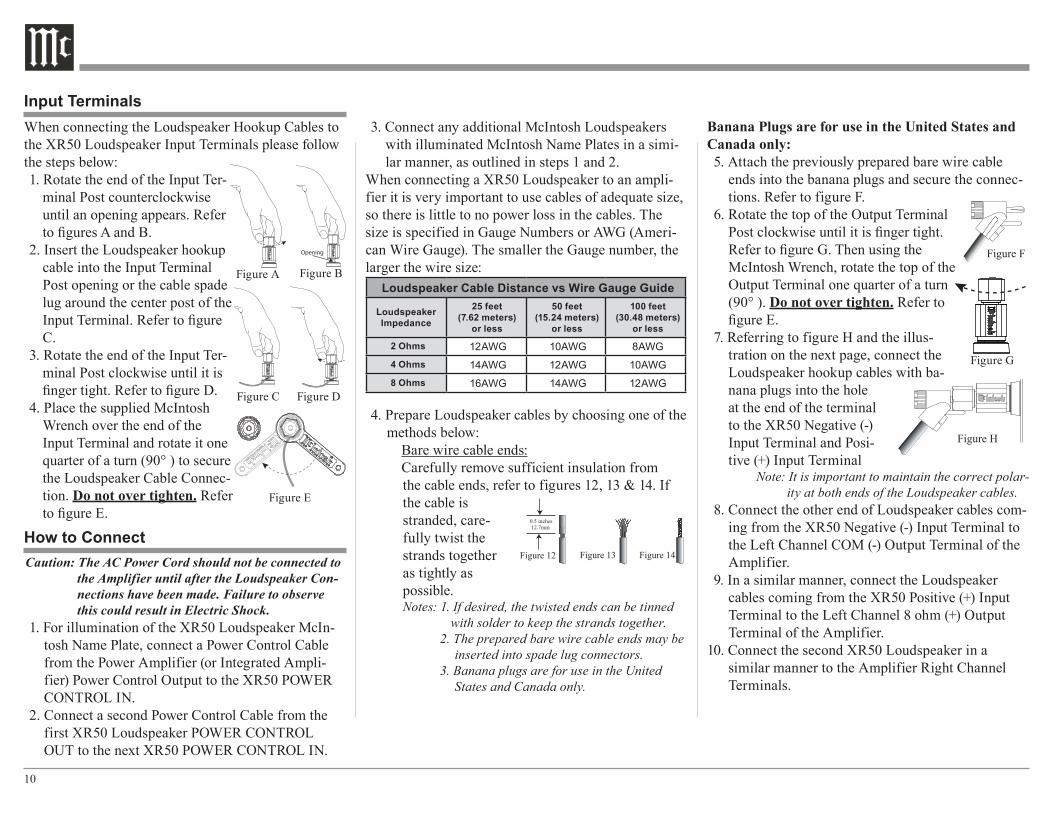
When connecting the Loudspeaker Hookup Cables to the XR50 Loudspeaker Input Terminals please follow the steps below:1. Rotate the end of the Input Ter-
minal Post counterclockwise until an opening appears. Refer to figures A and B.
2. Insert the Loudspeaker hookup cable into the Input Terminal Post opening or the cable spade lug around the center post of the Input Terminal. Refer to figure C.
3. Rotate the end of the Input Ter-minal Post clockwise until it is finger tight. Refer to figure D.
4. Place the supplied McIntosh Wrench over the end of the Input Terminal and rotate it one quarter of a turn (90° ) to secure the Loudspeaker Cable Connec-tion. Do not over tighten. Refer to figure E.
Caution: The AC Power Cord should not be connected to the Amplifier until after the Loudspeaker Con-nections have been made. Failure to observe this could result in Electric Shock.
1. For illumination of the XR50 Loudspeaker McIn-tosh Name Plate, connect a Power Control Cable from the Power Amplifier (or Integrated Ampli-fier) Power Control Output to the XR50 POWER CONTROL IN.
2. Connect a second Power Control Cable from the first XR50 Loudspeaker POWER CONTROL OUT to the next XR50 POWER CONTROL IN.
3. Connect any additional McIntosh Loudspeakers with illuminated McIntosh Name Plates in a simi-lar manner, as outlined in steps 1 and 2.
When connecting a XR50 Loudspeaker to an ampli-fier it is very important to use cables of adequate size, so there is little to no power loss in the cables. The size is specified in Gauge Numbers or AWG (Ameri-can Wire Gauge). The smaller the Gauge number, the larger the wire size:
Loudspeaker Cable Distance vs Wire Gauge Guide
LoudspeakerImpedance
25 feet(7.62 meters)
or less
50 feet(15.24 meters)
or less
100 feet(30.48 meters)
or less
2 Ohms 12AWG 10AWG 8AWG4 Ohms 14AWG 12AWG 10AWG8 Ohms 16AWG 14AWG 12AWG
4. Prepare Loudspeaker cables by choosing one of the methods below:
Bare wire cable ends:Carefully remove sufficient insulation from the cable ends, refer to figures 12, 13 & 14. If the cable is stranded, care-fully twist the strands together as tightly as possible.Notes: 1. If desired, the twisted ends can be tinned
with solder to keep the strands together.2. The prepared bare wire cable ends may be
inserted into spade lug connectors.3. Banana plugs are for use in the United
States and Canada only.
Banana Plugs are for use in the United States and Canada only:5. Attach the previously prepared bare wire cable
ends into the banana plugs and secure the connec-tions. Refer to figure F.
6. Rotate the top of the Output Terminal Post clockwise until it is finger tight. Refer to figure G. Then using the McIntosh Wrench, rotate the top of the Output Terminal one quarter of a turn (90° ). Do not over tighten. Refer to figure E.
7. Referring to figure H and the illus-tration on the next page, connect the Loudspeaker hookup cables with ba-nana plugs into the hole at the end of the terminal to the XR50 Negative (-) Input Terminal and Posi-tive (+) Input Terminal
Note: It is important to maintain the correct polar-ity at both ends of the Loudspeaker cables.
8. Connect the other end of Loudspeaker cables com-ing from the XR50 Negative (-) Input Terminal to the Left Channel COM (-) Output Terminal of the Amplifier.
9. In a similar manner, connect the Loudspeaker cables coming from the XR50 Positive (+) Input Terminal to the Left Channel 8 ohm (+) Output Terminal of the Amplifier.
10. Connect the second XR50 Loudspeaker in a similar manner to the Amplifier Right Channel Terminals.
How to ConnectFigure 12 Figure 13 Figure 14
Figure A
Opening
Figure B
Figure C Figure D
Figure E
Input Terminals
Figure F Figure H
Figure G
Figure F Figure H

11
How to Connect
Power Amplifier
6.6
Spade Lug or Wire Connections:11. Referring to the illustration on the next page, con-
nect the Loudspeaker hookup cables to the XR50 Negative (-) Input Terminal and Positive (+) Input Terminal. Insert the spade lug connector or pre-pared section of the cable end into the terminal side access hole, and tighten the termi-nal cap until the cable is firmly clamped into the terminals so the lugs or wire cannot slip out. Refer to figures 15 and 16.
Note: It is important to maintain the correct polar-ity at both ends of the Loudspeaker cables.
11. Connect the other end of Loudspeaker cables com-ing from the XR50 Negative (-) Input Terminal to the Left Channel COM (-) Output Terminal of the Amplifier.
12. In a similar manner, connect the Loudspeaker cables coming from the XR50 Positive (+) Input Terminal to the Left Channel 8 ohm (+) Output Terminal of the Amplifier.
13. Connect the second XR50 Loudspeaker to the Am-plifier in a similar manner.
14. Connect the second XR50 Loudspeaker in a similar manner to the Amplifier Right Channel Terminals.
Figure 15 Figure 16
XR50 Right Channel XR50 Left Channel

12

13
Photos

14
Specifications
Specifications General SpecificationsSystem Driver ComplementOne 6 inch Woofer (incorporating LD/HP1)Two 2 inch Titanium Inverted Dome MidrangesOne 3/4 inch Titanium Dome Tweeter
Impedance8 ohms Nominal
Frequency Response40Hz - 45,000Hz
Sensitivity81dB (2.83V/1m equivalent) Crossover Frequencies500Hz8,000Hz
Recommended Power Range75 Watts to 300 Watts
Maximum Power Handling300 Watts
Enclosure FinishAvailable in various real wood veneers witha high gloss polyester finish
Grille FinishBlack Knit Cloth
Overall DimensionsHeight is 17 inches (43.00cm)Width is 8 inches (20.30cm)Depth is 11-3/4 inches (29.85cm)
Weight19.5 pounds (8.9kg) net25 pounds (11.kg) in shipping carton
Shipping Carton DimensionsWidth is 15-1/2 inches (39.37cm)Depth is 12 inches (30.48cm)Height is 21 inches (53.34cm)
1LD/HP Pat. No 5,151,943

15
In the event it is necessary to repack the equipment for shipment, the equipment must be packed exactly as shown below. To protect the finish of the Loudspeaker it is advisable to wrap the Loudspeaker Cabinet with a durable plastic film. Then place wraped Loudspeaker into the protective fiber cover, before inserting it into the shipping carton.
Use the original shipping carton and interior parts only if they are all in good serviceable condition. If a shipping carton or any of the interior part(s) are needed, please call or write Customer Service Depart-ment of McIntosh Laboratory. Please see the Part List for the correct part numbers.
Quantity Part Number Description 1 03450700 Shipping carton 1 03451700 Top foam cap 1 03451600 Bottom foam cap 1 03452500 Protective fiber cover 1 03453400 Protective poly cover 1 03453300 Grille carton
Packing Instructions
Packing Instructions
TopFoamCap
BottomFoamCap
ShippingCarton
ProtectiveFiberCover
GrilleCarton
LoudspeakerGrille
ProtectivePolyCover

The continuous improvement of its products is the policy of McIntosh Laboratory Incorporated who reserve the right to improve design without notice.Printed in the U.S.A.
McIntosh Laboratory, Inc.2 Chambers Street
Binghamton, NY 13903www.mcintoshlabs.com
McIntosh Part No. 04126000