Embed Size (px)
Citation preview
xPilot: A Platform-Based System-Level Synthesis for xPilot: A Platform-Based System-Level Synthesis for
Reconfigurable SOCsReconfigurable SOCs
Prof. Jason CongProf. Jason Cong
[email protected]@cs.ucla.edu
UCLA Computer Science DepartmentUCLA Computer Science Department
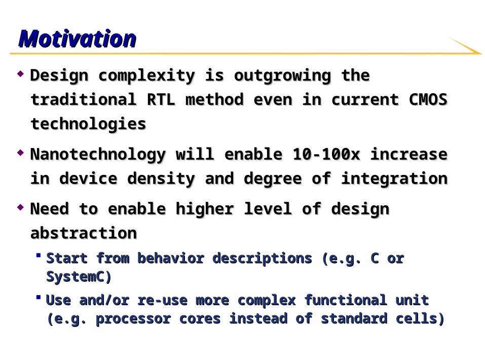
MotivationMotivation
Design complexity is outgrowing the traditional RTL Design complexity is outgrowing the traditional RTL
method even in current CMOS technologiesmethod even in current CMOS technologies
Nanotechnology will enable 10-100x increase in device Nanotechnology will enable 10-100x increase in device
density and degree of integrationdensity and degree of integration
Need to enable higher level of design abstractionNeed to enable higher level of design abstraction Start from behavior descriptions (e.g. C or SystemC)Start from behavior descriptions (e.g. C or SystemC)
Use and/or re-use more complex functional unit (e.g. processor Use and/or re-use more complex functional unit (e.g. processor cores instead of standard cells)cores instead of standard cells)
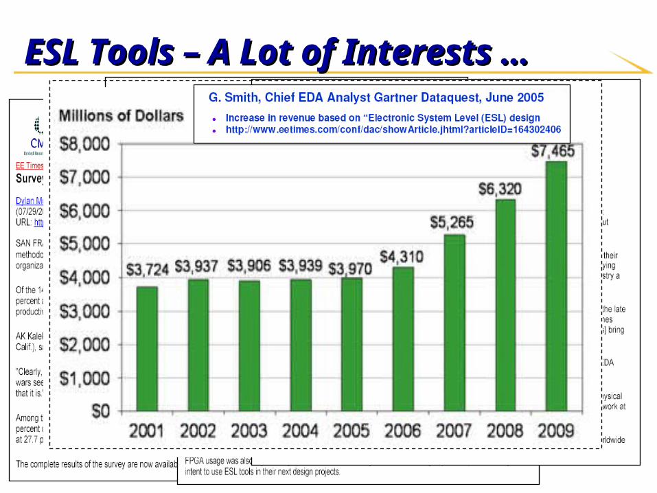
ESL Tools – A Lot of Interests …ESL Tools – A Lot of Interests …
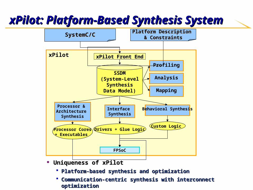
xPilot: Platform-Based Synthesis SystemxPilot: Platform-Based Synthesis System
xPilot
Behavioral SynthesisProcessor & Architecture
Synthesis
SSDM(System-Level
Synthesis Data Model)
FPSoC
Interface Synthesis
Analysis
Mapping
Profiling
Processor Cores+ Executables
Drivers + Glue LogicCustom Logic
xPilot Front EndxPilot Front End
SystemC/CSystemC/C Platform Description Platform Description & Constraints& Constraints
Uniqueness of xPilotUniqueness of xPilot Platform-based synthesis and optimizationPlatform-based synthesis and optimization Communication-centric synthesis with interconnect optimizationCommunication-centric synthesis with interconnect optimization
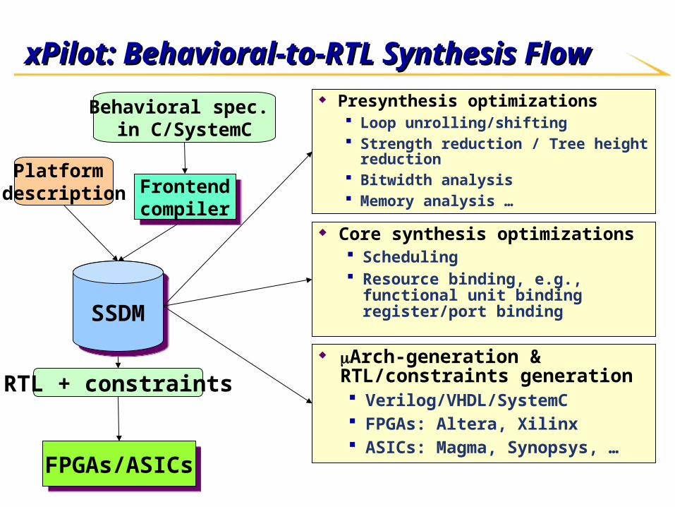
xPilot: Behavioral-to-RTL Synthesis Flow xPilot: Behavioral-to-RTL Synthesis Flow
Behavioral spec. in C/SystemC
RTL + constraints
SSDMSSDM
Arch-generation & RTL/constraints generation Verilog/VHDL/SystemC FPGAs: Altera, Xilinx ASICs: Magma, Synopsys, …
Presynthesis optimizations Loop unrolling/shifting Strength reduction / Tree height reduction Bitwidth analysis Memory analysis …
FPGAs/ASICsFPGAs/ASICs
Frontendcompiler
Frontendcompiler
Platform description
Core synthesis optimizations Scheduling Resource binding, e.g., functional unit
binding register/port binding
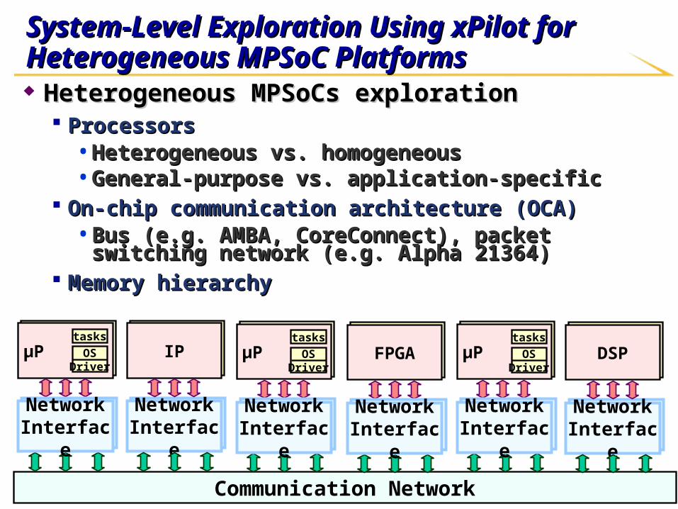
System-Level Exploration Using xPilot for System-Level Exploration Using xPilot for Heterogeneous MPSoC PlatformsHeterogeneous MPSoC Platforms Heterogeneous MPSoCs explorationHeterogeneous MPSoCs exploration
ProcessorsProcessors• Heterogeneous vs. homogeneousHeterogeneous vs. homogeneous• General-purpose vs. application-specificGeneral-purpose vs. application-specific
On-chip communication architecture (OCA)On-chip communication architecture (OCA)• Bus (e.g. AMBA, CoreConnect), packet switching network (e.g. Bus (e.g. AMBA, CoreConnect), packet switching network (e.g.
Alpha 21364)Alpha 21364) Memory hierarchyMemory hierarchy
μP
Communication Network
μP OSDriver
tasksμP
NetworkInterfaceNetwork
Interface
NetworkInterfaceNetwork
Interface
IP μP FPGA μP
NetworkInterfaceNetwork
Interface
NetworkInterfaceNetwork
Interface
DSPμP μP OSDriver
tasks
NetworkInterfaceNetwork
Interface
μP μP OSDriver
tasks
NetworkInterfaceNetwork
Interface
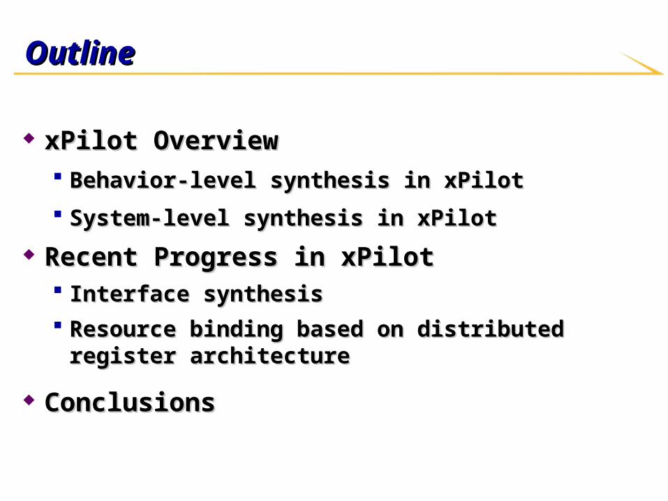
OutlineOutline
xPilot OverviewxPilot Overview Behavior-level synthesis in xPilotBehavior-level synthesis in xPilot
System-level synthesis in xPilotSystem-level synthesis in xPilot
Recent Progress in xPilotRecent Progress in xPilot Interface synthesisInterface synthesis Resource binding based on distributed register architectureResource binding based on distributed register architecture
ConclusionsConclusions
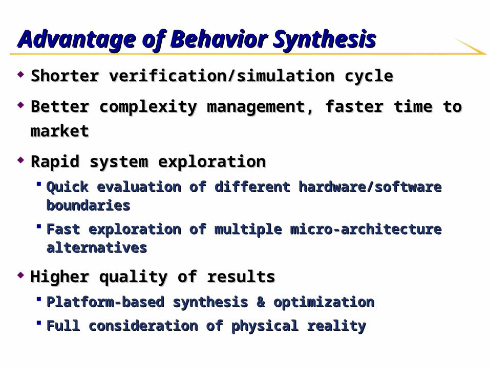
Advantage of Behavior SynthesisAdvantage of Behavior Synthesis
Shorter verification/simulation cycleShorter verification/simulation cycle
Better complexity management, faster time to marketBetter complexity management, faster time to market
Rapid system explorationRapid system exploration Quick evaluation of different hardware/software boundariesQuick evaluation of different hardware/software boundaries
Fast exploration of multiple micro-architecture alternativesFast exploration of multiple micro-architecture alternatives
Higher quality of resultsHigher quality of results Platform-based synthesis & optimizationPlatform-based synthesis & optimization
Full consideration of physical realityFull consideration of physical reality
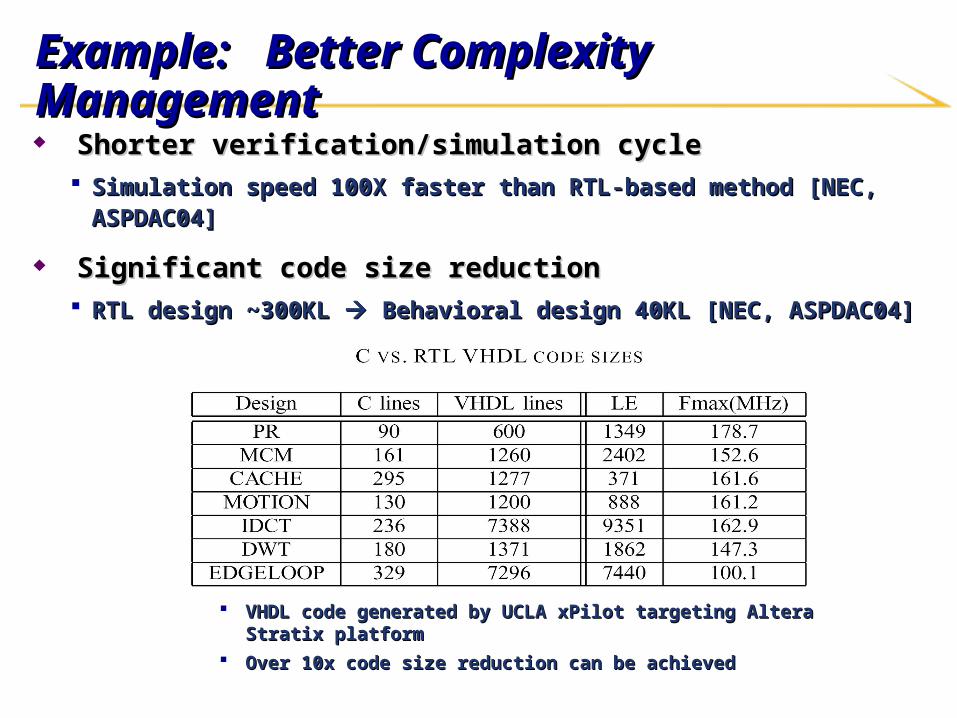
Example: Example: Better Complexity ManagementBetter Complexity Management Shorter verification/simulation cycleShorter verification/simulation cycle
Simulation speed 100X faster than RTL-based method [NEC, ASPDAC04]Simulation speed 100X faster than RTL-based method [NEC, ASPDAC04]
Significant code size reductionSignificant code size reduction RTL design ~300KL RTL design ~300KL Behavioral design 40KL [NEC, ASPDAC04] Behavioral design 40KL [NEC, ASPDAC04]
VHDL code generated by UCLA xPilot targeting Altera Stratix platformVHDL code generated by UCLA xPilot targeting Altera Stratix platform Over 10x code size reduction can be achievedOver 10x code size reduction can be achieved
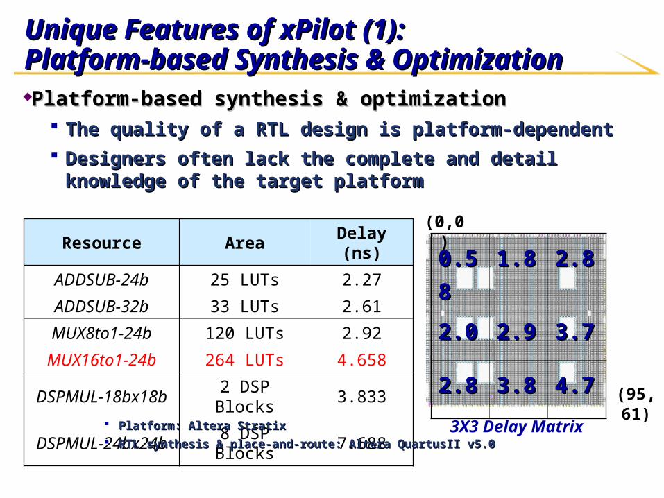
Unique Features of xPilot (1): Unique Features of xPilot (1): Platform-based Synthesis & OptimizationPlatform-based Synthesis & OptimizationPlatform-based synthesis & optimizationPlatform-based synthesis & optimization
The quality of a RTL design is platform-dependentThe quality of a RTL design is platform-dependent Designers often lack the complete and detail knowledge of the target Designers often lack the complete and detail knowledge of the target
platformplatform
Resource Area Delay (ns)
ADDSUB-24b 25 LUTs 2.27
ADDSUB-32b 33 LUTs 2.61
MUX8to1-24b 120 LUTs 2.92
MUX16to1-24b 264 LUTs 4.658
DSPMUL-18bx18b 2 DSP Blocks 3.833
DSPMUL-24bx24b 8 DSP Blocks 7.688
Platform: Altera StratixPlatform: Altera Stratix RTL synthesis & place-and-route: Altera QuartusII v5.0RTL synthesis & place-and-route: Altera QuartusII v5.0
0.580.58 1.81.8 2.82.8
2.02.0 2.92.9 3.73.7
2.82.8 3.83.8 4.74.7
3X3 Delay Matrix
(0,0)
(95,61)
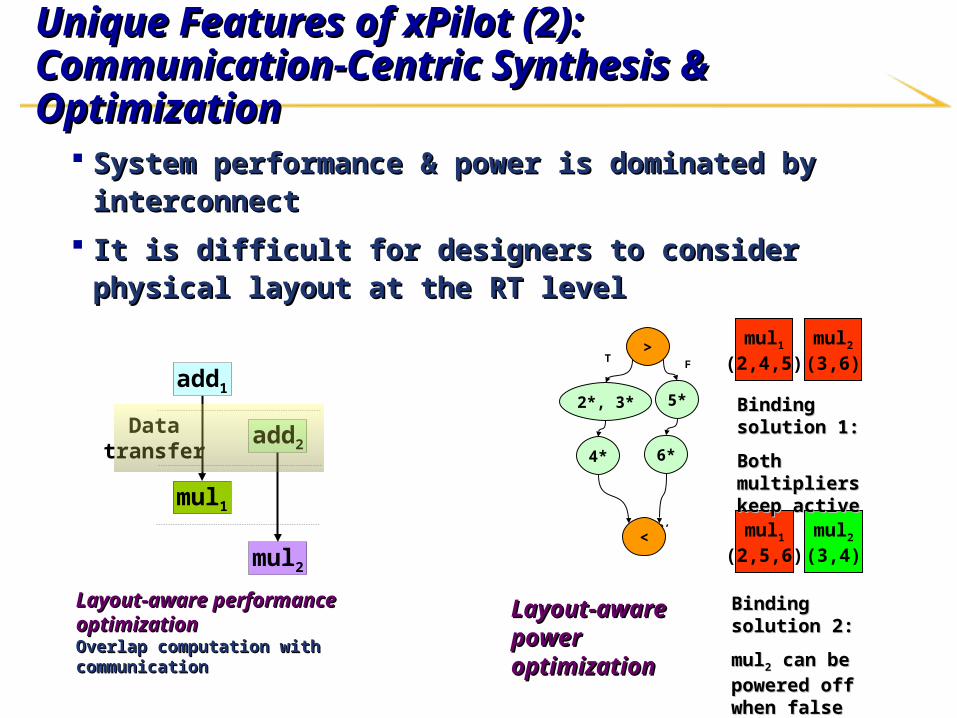
Unique Features of xPilot (2): Unique Features of xPilot (2): Communication-Centric Synthesis & Optimization Communication-Centric Synthesis & Optimization
System performance & power is dominated by interconnectSystem performance & power is dominated by interconnect
It is difficult for designers to consider physical layout at the RT It is difficult for designers to consider physical layout at the RT levellevel
Data transfer
add1
mul1
add2
mul2
Layout-aware performance Layout-aware performance optimizationoptimization Overlap computation with communicationOverlap computation with communication
Layout-aware power Layout-aware power optimizationoptimization
F
C2’
>
2*, 3* 5*
4*
< mul1
(2,5,6)mul2
(3,4)
6*
mul1
(2,4,5)mul2
(3,6)
Binding solution 2:Binding solution 2:
mulmul22 can be powered can be powered off when false branch off when false branch is taken is taken
T
Binding solution 1:Binding solution 1:
Both multipliers keep Both multipliers keep activeactive
Unique Features of xPilot (3):Unique Features of xPilot (3): Highly Scalable and Optimized Synthesis AlgorithmsHighly Scalable and Optimized Synthesis Algorithms
Use of highly scalable and optimized synthesis algorithms Use of highly scalable and optimized synthesis algorithms
for best quality of resultsfor best quality of results Interface synthesis: Simultaneous data and communication Interface synthesis: Simultaneous data and communication
scheduling for latency minimizationscheduling for latency minimization
Scheduling: A unified framework for multi-constraints and multi-Scheduling: A unified framework for multi-constraints and multi-objective scheduling based on the system of difference constraints objective scheduling based on the system of difference constraints (SDC)(SDC)
Resource binding: Use of distributed register architectures for Resource binding: Use of distributed register architectures for interconnect/communication optimizationinterconnect/communication optimization
Power optimization: Optimal functional module and voltage bindingPower optimization: Optimal functional module and voltage binding
……
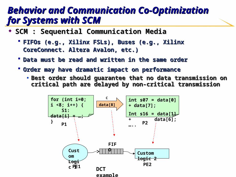
Behavior and Communication Co-Optimization Behavior and Communication Co-Optimization for Systems with SCMfor Systems with SCM SCM : Sequential Communication MediaSCM : Sequential Communication Media
FIFOs (e.g., Xilinx FSLs), Buses (e.g., Xilinx CoreConnect. Altera Avalon, etc.) FIFOs (e.g., Xilinx FSLs), Buses (e.g., Xilinx CoreConnect. Altera Avalon, etc.)
Data must be read and written in the same orderData must be read and written in the same order
Order may have dramatic impact on performanceOrder may have dramatic impact on performance• Best order should guarantee that no data transmission on critical path are Best order should guarantee that no data transmission on critical path are
delayed by non-critical transmissiondelayed by non-critical transmission
for (int i=0; i <8; i++) { S1: data[i] = …;}
int s07 = data[0] + data[7];
Int s16 = data[1] + data[6];…..
Custom Logic 1
Custom logic 2
DCT example
P1 P2
C
PE1 PE2
FIFO
data[8]
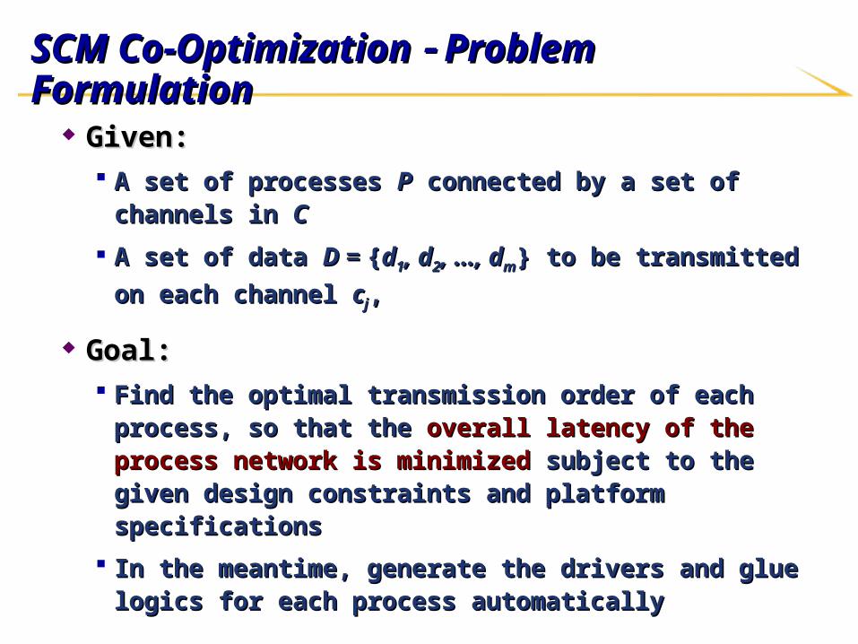
SCM Co-Optimization SCM Co-Optimization Problem Formulation Problem Formulation
Given:Given: A set of processes A set of processes PP connected by a set of channels in connected by a set of channels in CC
A set of data A set of data D = D = {{dd11, d, d22, …, d, …, dmm} to be transmitted on each } to be transmitted on each
channel channel ccjj, ,
Goal:Goal: Find the optimal transmission order of each process, so that Find the optimal transmission order of each process, so that
the the overall latency of the process network is minimizedoverall latency of the process network is minimized subject to the given design constraints and platform subject to the given design constraints and platform specificationsspecifications
In the meantime, generate the drivers and glue logics for each In the meantime, generate the drivers and glue logics for each process automaticallyprocess automatically
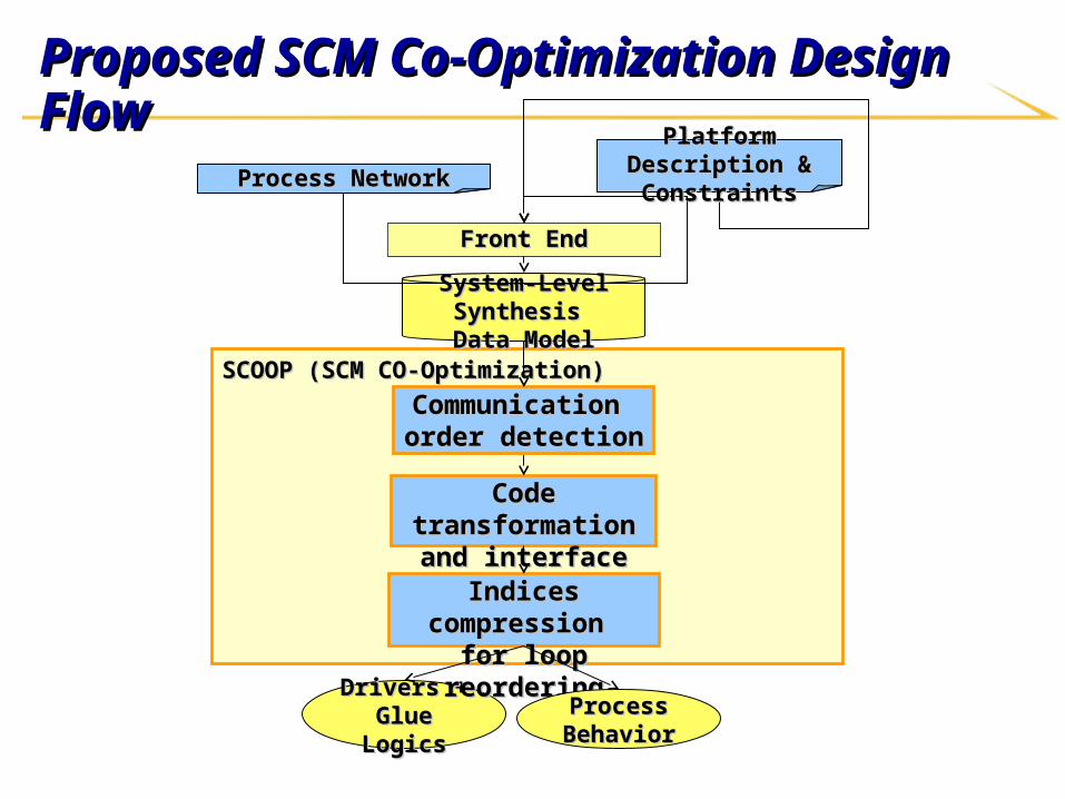
Proposed SCM Co-Optimization Design FlowProposed SCM Co-Optimization Design Flow
SCOOP (SCM CO-Optimization)SCOOP (SCM CO-Optimization)
System-Level Synthesis System-Level Synthesis Data ModelData Model
Code transformation and Code transformation and interface generationinterface generation
Drivers + Glue Drivers + Glue LogicsLogics
Front EndFront End
Process NetworkProcess NetworkPlatform Description & Platform Description &
ConstraintsConstraints
Communication Communication order detectionorder detection
Indices compression Indices compression for loop reorderingfor loop reordering
Process Process BehaviorBehavior
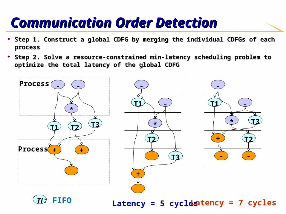
Communication Order DetectionCommunication Order Detection Step 1. Construct a global CDFG by merging the individual CDFGs of each processStep 1. Construct a global CDFG by merging the individual CDFGs of each process
Step 2. Solve a resource-constrained min-latency scheduling problem to optimize Step 2. Solve a resource-constrained min-latency scheduling problem to optimize the total latency of the global CDFG the total latency of the global CDFG
Process 1
Process 2 ++
T1 T2 T3
*
+
T1
T2
T3
*
+
T1
T2
T3
*
Latency = 5 cycles Latency = 7 cyclesTi : FIFO
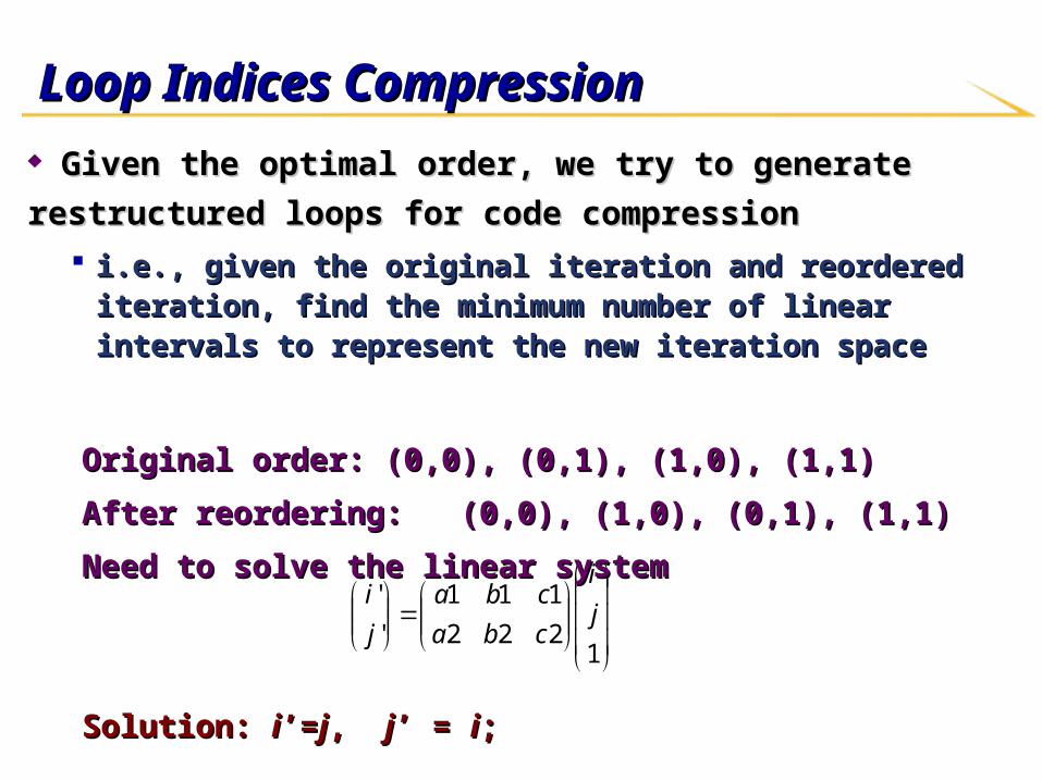
Loop Indices CompressionLoop Indices Compression
Given the optimal order, we try to generate restructured loops for Given the optimal order, we try to generate restructured loops for
code compressioncode compression
i.e., given the original iteration and reordered iteration, find the minimum i.e., given the original iteration and reordered iteration, find the minimum number of linear intervals to represent the new iteration spacenumber of linear intervals to represent the new iteration space
12
1
2
1
2
1
'
'j
i
c
c
b
b
a
a
j
i
Original order: (0,0), (0,1), (1,0), (1,1)Original order: (0,0), (0,1), (1,0), (1,1)
After reordering: (0,0), (1,0), (0,1), (1,1)After reordering: (0,0), (1,0), (0,1), (1,1)
Need to solve the linear systemNeed to solve the linear system
Solution: Solution: ii’=’=jj, , jj’ = ’ = ii; ;
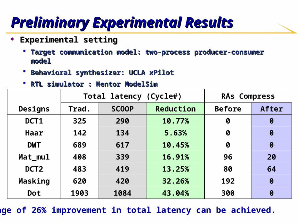
Preliminary Experimental ResultsPreliminary Experimental Results
Total latency (Cycle#) RAs Compress
Designs Trad. SCOOP Reduction Before After
DCT1 325 290 10.77% 0 0
Haar 142 134 5.63% 0 0
DWT 689 617 10.45% 0 0
Mat_mul 408 339 16.91% 96 20
DCT2 483 419 13.25% 80 64
Masking 620 420 32.26% 192 0
Dot 1903 1084 43.04% 300 0
An average of 26% improvement in total latency can be achieved.
Experimental settingExperimental setting Target communication model: two-process producer-consumer modelTarget communication model: two-process producer-consumer model
Behavioral synthesizer: UCLA xPilotBehavioral synthesizer: UCLA xPilot
RTL simulator : Mentor ModelSim RTL simulator : Mentor ModelSim
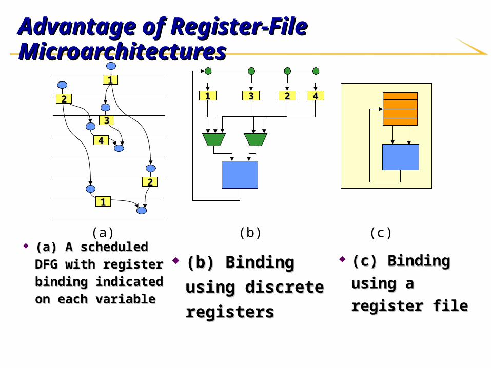
Advantage of Register-File Microarchitectures Advantage of Register-File Microarchitectures
(a) A scheduled (a) A scheduled
DFG with register DFG with register
binding indicated binding indicated
on each variable on each variable
11
22
44
33
11
22
33 22 4411
(a) (c)(b)
(b) Binding using (b) Binding using
discrete registers discrete registers
(c) Binding (c) Binding
using a register using a register
file file
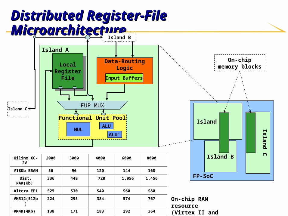
Distributed Register-File MicroarchitectureDistributed Register-File Microarchitecture
Island A
Data-RoutingLogicLocal
RegisterFile
LocalRegister
File
FUP MUX
Functional Unit Pool
MULALU
ALU’
Island C
Island B
Input Buffers
Xilinx XC-2V 2000 3000 4000 6000 8000
#18Kb BRAM 56 96 120 144 168
Dist. RAM(Kb) 336 448 720 1,056 1,456
Altera EP1 S25 S30 S40 S60 S80
#M512(512b) 224 295 384 574 767
#M4K(4Kb) 138 171 183 292 364
#M-(512Kb) 2 4 4 6 9
FP-SoC
Island A
Island B
Island
C
On-chip memory blocks
On-chip RAM resource(Virtex II and Stratix)
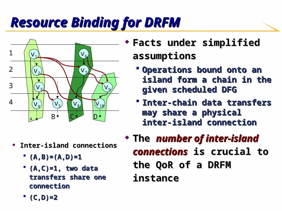
Resource Binding for DRFMResource Binding for DRFM Facts under simplified Facts under simplified
assumptionsassumptions Operations bound onto an island Operations bound onto an island
form a chain in the given form a chain in the given scheduled DFGscheduled DFG
Inter-chain data transfers may Inter-chain data transfers may share a physical inter-island share a physical inter-island connectionconnection
The The number of inter-island number of inter-island connectionsconnections is crucial to the is crucial to the QoR of a DRFM instanceQoR of a DRFM instance
v1
v2
v4
v3
v5 v8 v10
A B C D
1
2
3
4
v7
v6
v9
Inter-island connectionsInter-island connections
(A,B)=(A,D)=1(A,B)=(A,D)=1
(A,C)=1, two data transfers (A,C)=1, two data transfers share one connectionshare one connection
(C,D)=2(C,D)=2
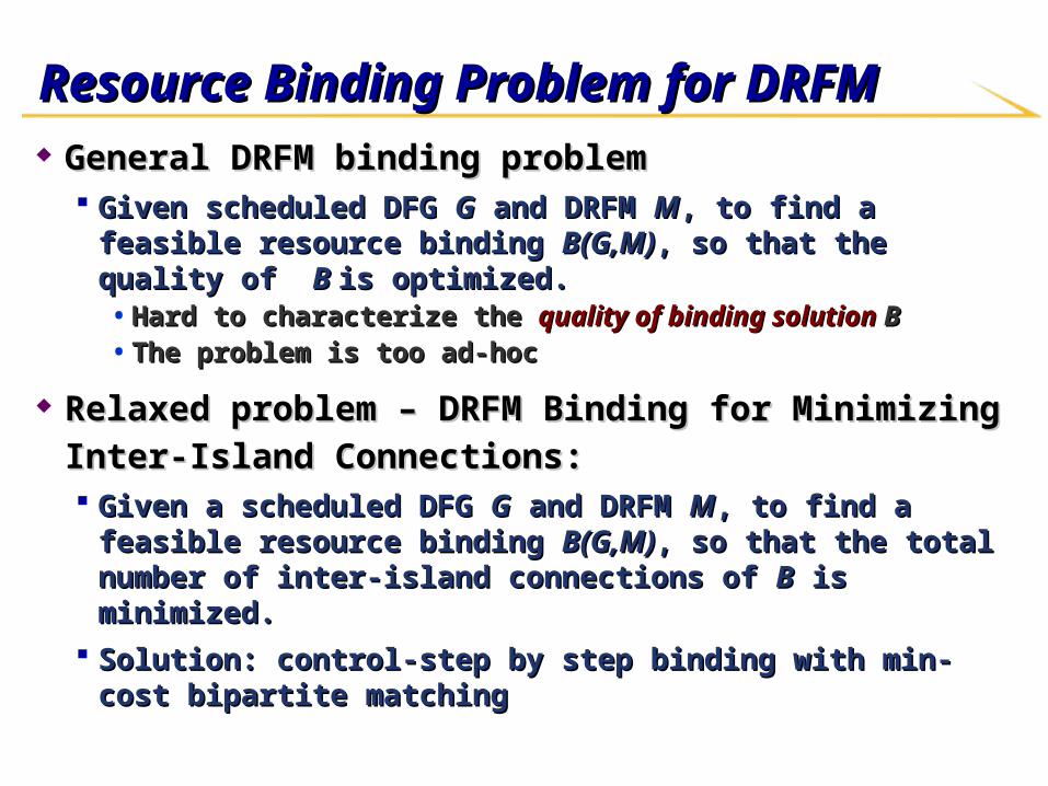
Resource Binding Problem for DRFMResource Binding Problem for DRFM General DRFM binding problemGeneral DRFM binding problem
Given scheduled DFG Given scheduled DFG GG and DRFM and DRFM MM, to find a feasible resource , to find a feasible resource binding binding B(G,M)B(G,M), so that the quality of , so that the quality of B B is optimized. is optimized. • Hard to characterize the Hard to characterize the quality of binding solution quality of binding solution BB• The problem is too ad-hocThe problem is too ad-hoc
Relaxed problem – DRFM Binding for Minimizing Inter-Relaxed problem – DRFM Binding for Minimizing Inter-Island Connections: Island Connections: Given a scheduled DFG Given a scheduled DFG GG and DRFM and DRFM MM, to find a feasible , to find a feasible
resource binding resource binding B(G,M)B(G,M), so that the total number of inter-island , so that the total number of inter-island connections of connections of BB is minimized. is minimized.
Solution: control-step by step binding with min-cost bipartite Solution: control-step by step binding with min-cost bipartite matchingmatching
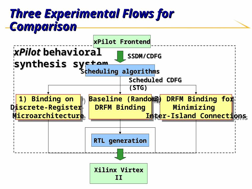
Three Experimental Flows for Comparison Three Experimental Flows for Comparison
xPilot xPilot behavioral behavioral synthesis systemsynthesis system
SSDM/CDFGSSDM/CDFG
Scheduling algorithmsScheduling algorithms
RTL generationRTL generation
Scheduled CDFG (STG)Scheduled CDFG (STG)
2) Baseline (Random) DRFM Binding
2) Baseline (Random) DRFM Binding
3) DRFM Binding for Minimizing
Inter-Island Connections
3) DRFM Binding for Minimizing
Inter-Island Connections
1) Binding on Discrete-Register Microarchitecture
1) Binding on Discrete-Register Microarchitecture
Xilinx Virtex IIXilinx Virtex II
xPilot FrontendxPilot Frontend
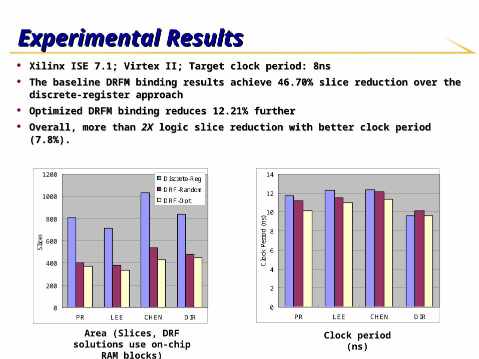
Experimental ResultsExperimental Results Xilinx ISE 7.1; Virtex II; Target clock period: 8nsXilinx ISE 7.1; Virtex II; Target clock period: 8ns The baseline DRFM binding results achieve 46.70% slice reduction over the discrete-register The baseline DRFM binding results achieve 46.70% slice reduction over the discrete-register
approachapproach Optimized DRFM binding reduces 12.21% furtherOptimized DRFM binding reduces 12.21% further Overall, more than Overall, more than 2X2X logic slice reduction with better clock period (7.8%). logic slice reduction with better clock period (7.8%).
0
200
400
600
800
1000
1200
PR LEE CHEN DIR
Sli
ces
Discrete-Reg
DRF-Random
DRF-Opt
0
2
4
6
8
10
12
14
PR LEE CHEN DIR
Clo
ck P
erio
d (
ns)
Area (Slices, DRF solutions use on-chip RAM blocks)
Clock period (ns)
ConclusionsConclusions xPilot can automatically synthesize behavior level C or SystemC xPilot can automatically synthesize behavior level C or SystemC
presentation to RTL code with necessary design constraintspresentation to RTL code with necessary design constraints Platform-based synthesis with physical planning providesPlatform-based synthesis with physical planning provides
Shorter verification/simulation cycleShorter verification/simulation cycle Better complexity management, faster time to marketBetter complexity management, faster time to market Rapid system explorationRapid system exploration Higher quality of resultsHigher quality of results
xPilot can help to explore the efficient use of (multiple) on-chip xPilot can help to explore the efficient use of (multiple) on-chip processorsprocessors
xPilot can efficiently optimize the software for reconfigurable xPilot can efficiently optimize the software for reconfigurable processorsprocessors
We are interested to engage with selected industrial partners to We are interested to engage with selected industrial partners to further validate and enhance the technologyfurther validate and enhance the technology
AcknowledgementsAcknowledgements We would like to thank the supports from We would like to thank the supports from
National Science Foundation (NSF)National Science Foundation (NSF)
Gigascale Systems Research Center (GSRC) Gigascale Systems Research Center (GSRC)
Semiconductor Research Corporation (SRC)Semiconductor Research Corporation (SRC)
Industrial sponsors under the California MICRO programs (Altera, Xilinx)Industrial sponsors under the California MICRO programs (Altera, Xilinx)
Team members:Team members:
Yiping FanYiping Fan Zhiru ZhangZhiru ZhangWei JiangWei JiangGuoling HanGuoling Han