Embed Size (px)
DESCRIPTION
xpfm
Citation preview
Tampa, FL 33542
XPFM_03_03/07Technical Support: (800) 832-4003
Fixture Module 15A, Non Dimming XPFM
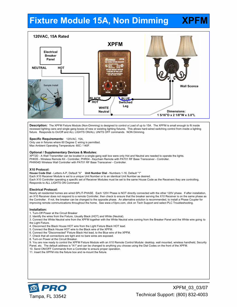
Description: The XPFM Fixture Module (Non-Dimming) is designed to control a Load of up to 15A. The XPFM is small enough to fit insiderecessed lighting cans and single gang boxes of new or existing lighting fixtures. This allows hard-wired switching control from inside a lightingfixture. Responds to On/Off and ALL LIGHTS ON/ALL UNITS OFF commands. NON Dimming.
Specific Requirements: 120VAC, 15A,Only use in fixtures where 60 Degree C wiring is permitted.Max Ambient Operating Temperature: 60C / 140F.
Optional / Supplementary Devices & Modules:XPT2D - A Wall Transmitter can be located in a single-gang wall box were only Hot and Neutral are needed to operate the lights.PHK05 - Wireless Remote Kit - Controller, PHR04 - Keychain Remote with PAT01 RF Base Transceiver - Controller.PHW04D Wireless Wall Controller with PAT01 RF Base Transceiver - Controller.
X10 Protocol:House Code Dial - Letters A-P, Default "A" Unit Number Dial - Numbers 1-16, Default "1"Each X10 Receiver Module is set to a unique Unit Number or to an identical Unit Number as desired.Each X10 Controller operating a specific set of Receiver Modules must be set to the same House Code as the Receivers they are controlling.Responds to ALL LIGHTS ON Command
Electrical Protocol:Nearly all residential homes are wired SPLIT-PHASE. Each 120V Phase is NOT directly connected with the other 120V phase. If after installation,an X10 Receiver does not respond to a remote Controller, then check to ensure that the breaker serving the X10 Receiver is on the same phase asthe Controller. If not, the breaker can be changed to the opposite phase. An alternative solution is recommended, to install a Phase Coupler forimproving remote communications throughout the home. See www.x10pro.com, click on Tech Support and select PLC Troubleshooting.
Installation:1. Turn-Off Power at the Circuit Breaker2. Identify the wires from the Fixture, Usually Black (HOT) and White (Neutral).3. Connect the White Neutral wire from the XPFM together with the White Neutral wire coming from the Breaker Panel and the White wire going tothe Light Fixture.4. Disconnect the Black House HOT wire from the Light Fixture Black HOT lead.5. Connect the Black House HOT wire to the Black wire of the XPFM.6. Connect the "Disconnected" Fixture Black Hot lead, to the Blue wire of the XPFM.7. Check that all connections are tight and no bare wires are exposed.8. Turn-on Power at the Circuit Breaker.9. You are now ready to control the XPFM Fixture Module with an X10 Remote Control Module: desktop, wall mounted, wireless handheld, SecurityPanel, etc. The default address is "A1" and can be changed to anything you choose using the Dial Codes on the front of the XPFM.10. Send ON/OFF Commands from a Controller to ensure proper operation.11. Insert the XPFM into the fixture box and re-mount the fixture.
ElectricalBreakerPanel
HOTNEUTRAL
Dimensions:1 5/16"D x 2 1/8"W x 3.0"L
XPFM120VAC, 15A Rated
Sample Install Wall Sconce
BLUESwitched
LegWHITENeutral
BLACKHOT


