Embed Size (px)
Citation preview

Operating instructions
Art. No.: 04841533Version: 04/04
Explorer Project XP128


LUXMATE Explorer Project 1
Contents
Copyright.....................................................................................................................3
Customer Support .........................................................................................................3
Validity and technical state of this manual.......................................................................3
1 Notes regarding security and use of the operating instructions ..................................41.1 Use of symbols and identification of security notes .......................................... 41.2 Important notes regarding industrial and operational safety............................. 51.3 Notes on illustrations and circuit diagrams ..................................................... 5
2 Product description................................................................................................62.1 Specified use................................................................................................ 62.2 Description................................................................................................... 72.3 Example circuit............................................................................................. 82.4 Technical Data ............................................................................................. 92.5 Communication and data exchange............................................................. 10
2.5.1 Communication and data exchange interfaces .................................... 10
3 Installation ..........................................................................................................113.1 Who may perform the installation? .............................................................. 113.2 Installing Explorer Project XP128 ................................................................. 113.3 Connecting the eDALI bus ........................................................................... 113.4 Installing and connecting external modules ................................................... 123.5 Connecting a remote display ....................................................................... 133.6 Connecting the 230 V mains supply............................................................. 133.7 Completing the installation .......................................................................... 14
4 Commissioning ...................................................................................................154.1 Important notes prior to commissioning ........................................................ 154.2 General notes concerning operation ............................................................ 15
4.2.1 Operating elements .......................................................................... 164.2.2 LED indicators at the device ............................................................... 16
4.3 Control keys on touch panel ........................................................................ 174.4 Quick installation ....................................................................................... 20
4.4.1 Luminaires assignment ...................................................................... 204.4.2 Luminaires settings............................................................................ 23
5 Basic display.......................................................................................................245.1 Overview................................................................................................... 245.2 Display ...................................................................................................... 24

2 LUXMATE Explorer Project
5.3 Touch panel keys ........................................................................................255.4 Block system (quick menu) ...........................................................................255.5 Start function test (quick menu).....................................................................265.6 Start duration test (quick menu) ....................................................................26
6 Test functions...................................................................................................... 276.1 Overview ...................................................................................................276.2 Test book....................................................................................................276.3 Function test ...............................................................................................286.4 Duration test ...............................................................................................296.5 Relay / buzzer test......................................................................................31
7 Luminaires.......................................................................................................... 327.1 Overview ...................................................................................................327.2 Luminaires status.........................................................................................327.3 Luminaires settings ......................................................................................337.4 Luminaires assignment.................................................................................347.5 Setting up groups with Explorer Project Extender ...........................................387.6 Assigning luminaires via GSM mobile phone ................................................407.7 Setting up single luminaires .........................................................................41
8 Error assignments to relays / buzzer / GSM......................................................... 428.1 Overview ...................................................................................................428.2 Status.........................................................................................................428.3 Assignments ...............................................................................................42
9 External devices.................................................................................................. 449.1 Overview ...................................................................................................449.2 Explorer Project GSM Module......................................................................449.3 Printer ........................................................................................................47
10 Device configuration ........................................................................................... 4810.1 Overview ...................................................................................................4810.2 Options......................................................................................................4810.3 Display ......................................................................................................4910.4 Service.......................................................................................................49
11 Error check lists for the Explorer Project system...................................................... 5111.1 Using the error detection tables ....................................................................5111.2 Error detection for emergency exit sign luminaires / security luminaires with
EM-IF Module .............................................................................................52

LUXMATE Explorer Project 3
CopyrightWithout the expressed written permission of Thorn Lighting Limited, no part of this manual may be reproduced, published or transmitted in any form or by any means.
© 2004 Thorn Lighting Limited. All rights reserved.
Customer SupportFor information, support concerning technical problems, services and orders please contact your local Thorn office.
Validity and technical state of this manualThis operating manual only relates to devices of the type Explorer Project XP128 with theSAP Code: 22 154 297.
Technical modifications made after printing this manual are not considered. Subject to changes.
Issue date: Version 04/04.

4 LUXMATE Explorer Project
1 Notes regarding security and use of the operating instructions
1.1 Use of symbols and identification of security notes
InstructionThis symbol indicates that the described instruction has to be performed by the user.
Displays and messagesThis symbol indicates that the described values or texts are shown in the display or contained in messages and can not be edited.
NoteThis symbol represents a reference to hints and recommendations which are useful when performing the instructions and handling the device or system components.
Caution!This symbol warns of improper handling. Disregarding the instructions may result in damages to system components.
Warning!This symbol points to sources of danger which may cause personal injuries or severe damages to system components.
Danger!This symbol points to sources of danger which may cause critical personal injuries or acute damages to system components.

LUXMATE Explorer Project 5
1.2 Important notes regarding industrial and operational safetyThe device is part of the emergency and general lighting and consequently part of a building's safety equipment. Thus, appropriate care and precision are to be applied when installing and commissioning the system.
Warning!The system is designed to be professionally installed and requires commissioning. Failure to comply with these requirements may result in equipment malfunction and a non-conforming emergency lighting system. No liability for consequential damages can be accepted by the company.
During normal operation the following maintenance operations have to be performed continuously:• Regular checking and inspection of the system.• Inspection and logging of device functions.• Safety procedures in the event of failures.
NoteInspections, safety tests and documentation are restricted to authorised technical staff.National laws and guidelines are to be observed, regarding• execution of inspections and safety tests and• implementation of general and emergency lighting.
1.3 Notes on illustrations and circuit diagramsIllustrations and circuit diagrams in these installation and operating instructions are for demonstration purposes only. Drawings and plans were specially created for the illustration and may not be in accordance with local requirements which must be observed.

6 LUXMATE Explorer Project
2 Product description
2.1 Specified useThe Explorer Project XP128 is intended for controlling and monitoring emergency lighting systems. Commissioning and operation of the system is restricted to authorised technical staff.
Personal danger may occur in case of• improper use or• non-observance of safety regulations.
The device and connected system components may only be operated if these are in perfect technical condition and comply with• the safety and danger notes contained in these installation instructions,• operating and safety instructions stipulated by the system operator,• installation and operating data listed in section 2.4 on page 9.
Failures are to be reported to management and rectified.
Operating and safety regulations arise from these installation instructions as well as organisational instructions by management, and general as well as technical guidelines and regulations for accident prevention.
The manufacturer will not assume warranty or liability for consequential damages that occur due to:• improper use,• non-observance of regulations,• unauthorised modifications or modifications made by unqualified persons to device
connections and settings,• operating unauthorised or unsuitable devices or device groups.
Caution!Also pay attention to all laws, norms and guidelines applicable in the country in which the system is being installed and operated.
Verify that the electrical installations comply with the relevant regulations.
Verify that all luminaires meet the requirements of an emergency lighting system and the operation of an Explorer Project system.
Verify that all emergency luminaires are compatible for use with Explorer Project.

LUXMATE Explorer Project 7
2.2 DescriptionThe Explorer Project XP128 is used for central control and monitoring of self contained emergency luminaires via the eDALI bus (eDALI = enhanced Digital Addressable Lighting Interface).
The Explorer Project XP128 monitors up to 64 luminaires on each of two output groups. The maximum cable length from controller to the last luminaire can be up to 300 m (line cross section at least 1.5 mm²). By using the XPX64 Extender devices, the complete installation can be expanded to 256 monitored luminaires. The maximum cable length from the expander to the luminaire can be up to 300m.
All settings of the Explorer Project XP128 are stored to a non-volatile memory, which means that the settings will not get lost even if the device is completely switched off. Via infrared interface provided on the controller front panel, a printer or PC can be connected. Thus, the configuration can also be performed at the PC and then transmitted to the controller instead of using the touch panel. Additionally, the Explorer Project XP128 configuration data can be transferred to the PC for archiving purposes.
The Explorer Project XP128 monitors the emergency luminaires by communicating via the eDALI bus. Each emergency luminaire is monitored individually and the result is indicated on the display.
The Explorer Project system provides the following supplementary functions:• Automatic addressing and monitoring of luminaires
Each emergency luminaire equipped with an emergency ballast is detected by the Explorer Project XP128 and assigned to the corresponding eDALI group. This means each luminaire can be monitored and operated individually.
• Volt-free alarm contacts for remote indication of the operating stateThree potential-free alarm contacts are available for a remote indication of the Explorer Project system’s operating state. The system events can be freely assigned to the alarm contacts.
• Failure reports and luminaire configuration via GSM-mobile radio communication (optional)The Explorer Project GSM Module, which is connected to the Explorer Project XP128, facilitates one man commissioning using a mobile phone. Failure reports can be sent as a text message to the maintainer's mobile phone.
• Printing test protocols (optional)The XPPRI printer which communicates to the Explorer Project XP128 via the infrared port, which is used to print the test results and the current configuration of the installation.

8 LUXMATE Explorer Project
2.3 Example circuit
Figure: Circuit diagram of an Explorer Project system

LUXMATE Explorer Project 9
2.4 Technical Data
Designation: Explorer Project XP128 Art.-No.: 22 154 297
Permitted input voltage: 230V AC ±10%; 50 ... 60 HzLoss power < 10 W
Connections Power supply L/N/PE RS232 interface - TxD / RxD / GND (3 terminals) 2x eDALI outputs max. 300 m (capacity max. 64 DALI devices) 3 potential-free alarm contacts (contact raiting: max. 24 V AC/DC
2 A)Terminals 0.75 ... max. 2.5 mm²
Interface RS 232; 19200 Baud; [8bit, 1 start bit, 1 stop bit, no parity] IR; 19200 - 115k Baud; [8bit, 1 start bit, 1 stop bit, no parity]
Protection type IP20Housing material Flame-resistant polycarbonateDimensions 130 x 155 x 65 mmAmbient temperature limit 0 ... +40 °CWeight Approx. 0.7 kg
Other Max. cable length 3 m (RS232) Max. range 1 m (IR)

10 LUXMATE Explorer Project
Optional modulesXPX64: Allows expansion from 128 up to 256 emergency luminaires.
XPGSM: GSM mobile radio communication for setting up luminaires and reporting failure messages via SMS (Short Message Service).
XPPSU: Power supply for XPGSM module.
XPPRI: Infrared printer for printing test protocols and system configuration data.
2.5 Communication and data exchange
2.5.1 Communication and data exchange interfaces
IR interface
The IR interface located on the Explorer Project XP128 front panel establishes a direct connection to the XPPRI printer or to an external PC (e.g. a Notebook). Via this interface the current configuration data as well as the test protocols can be read out and archived and it is possible to configure the controller.
RS 232 interface
The serial RS 232 interface allows a data connection to the optional GSM module.
eDALI bus
Via the eDALI bus (enhanced Digital Addressable Lighting Interface, terminals D1, D2) the Explorer Project XP128 is able to communicate with self contained emergency luminaires.

LUXMATE Explorer Project 11
3 Installation
Warning!Only qualified electrical specialists may perform work on the 230 V mains.
Wiring of current-carrying lines as well as signal and control lines must be done in accordance with the relevant guidelines and norms.
National guidelines and regulations applicable in the country in which the system is being installed and operated have to be observed.
3.1 Who may perform the installation?In principle the installation may only be performed by suitably qualified professional electrical specialists who have been briefed on local and operational conditions. Others may only perform the installation under the supervision and control of authorized technical staff, after having received appropriate briefing and if the tasks and jobs have been fully understood.
3.2 Installing Explorer Project XP128The Explorer Project XP128 can be mounted using the drilling holes in the rear panel or on a hat rail according to EN 50022.
The hole diameter is 3.5 mm.
3.3 Connecting the eDALI busConnect the cables for the first eDALI bus to the terminals A-D1 and A-D2 and the cable of the second bus to the terminals B-D1 and B-D2. The bus is not polarity conscious.
Line cross sections for eDALI bus lines
up to 100 m: 0.5 mm2
100 up to 150 m: 0.75 mm2
150 up to 300 m: 1.5 mm2

12 LUXMATE Explorer Project
3.4 Installing and connecting external modules
Warning!Prior to installing, both the Explorer Project XP128 and the device to be connected must be switched off.
You may connect an Explorer Project GSM module to the serial RS 232 interface.
Connect the RS 232 cable to the terminals Rx, Tx and Gnd of the Explorer Project XP128. Connect the other end of the RS 232 cable to the terminals Rx, Tx and Gnd of the Explorer Project GSM module.
Caution!Ensure that the same wires are connected to the terminals with identical labels at both devices. The maximum allowed RS 232 cable length is 3 meters. Furthermore, take note of the information given in section 2.4 on page 9.
Figure: RS 232 connection between Explorer Project XP128 and Explorer ProjectGSM module
RS 232 cable

LUXMATE Explorer Project 13
3.5 Connecting a remote display
Warning!Do not switch on voltage supply (230 V mains power supply) until all wiring and installation activities have been completed.
Connection of the remote display is done via the potential-free alarm contacts of the relays 1 to 3.
Connection of the remote display has to be made in accordance with:• the manufacturer's information for the remote
display.• the accompanying schematic drawing.
Alarm contacts:K11-K14 NO K11-K12 NCK21-K24 NO K21-K22 NCK31-K34 NO K31-K32 NCNO: normally openNC: normally closed
• the contact rating:max. voltage: 24 V AC/DCmax. current: 2 A
• the plans and drawings according to the conditions at the installation site.
The assignment of system and error messages to the relays 1 to 3 corresponds to DIN VDE 0108 by default. When commissioning the system the assignment can be configured as desired.
3.6 Connecting the 230 V mains supplyThe Explorer Project XP128 is powered by the general 230 V, 50/60 Hz mains supply.
Connect the 230 V mains supply to the screw terminals L, N and PE of the Explorer Project XP128 while mains supply is switched off.
Remotedisplay
Terminals and schematic diagram for remote display
Mainssupply
Terminals for 230 V voltage supply

14 LUXMATE Explorer Project
3.7 Completing the installationThe following operations and tests have to be done after installation:• Perform a final check on all operations executed and compare the established connections
with the plans and drawings.• Check that all connections are tight.• Remove all unused cables, insulation and fixing materials, tools and packaging.

LUXMATE Explorer Project 15
4 Commissioning
4.1 Important notes prior to commissioningTake note of the following instructions before initial commissioning, modifications or repairs:• Commissioning may only be performed by an authorised electrical specialist having
specialised knowledge of technical and legal principles for set up and operation of emergency lighting systems.
• In addition, observe national regulations and guidelines for commissioning and operation of emergency power lighting systems.
• Observe all measures for work safety.• Before commissioning, check that the installation activities have been performed and
completed according to regulations.• Compare all work performed with the plans and drawings.
4.2 General notes concerning operationThe Explorer Project XP128 is a menu driven system, operated via the touch panel located on the front panel. All messages (system, status and error messages) are displayed on the touch panel. Selecting menus or tabs, entering and editing parameters as well as executing commands is done by means of appropriate control keys and device symbols. These keys or symbols can be operated by the stylus provided or your finger. When touching the panel, its background lighting is activated automatically and extinguishes after 20 seconds without any input. After 60 seconds the panel automatically returns to the basic display, if there are no setting changes to be confirmed or active procedures (e.g. running tests).
NoteWe recommend to use only the stylus delivered for operating the touch panel. Otherwise the touch panel may be damaged.

16 LUXMATE Explorer Project
4.2.1 Operating elements
Figure: Touch panel operating elements with basic display shown (example)
4.2.2 LED indicators at the device
LED "Power"
LED lights Mains supply available, everything is OK.
LED flashes Function test or duration test is running.
LED "Fault"
LED lights Failure. A failure has occurred during a duration test or a function test. To eliminate a failure the test has to be performed again with a positive result.
LED flashes Explorer Project XP128 is blocked, see section5.4 on page 25.
Touch panel keys:
leads to quick menu and menu selection
shows test book information
leads to help menu
leads to display and input area

LUXMATE Explorer Project 17
4.3 Control keys on touch panel
Graphically represented control keys (navigation and command keys, etc.) are available on the screen for operating the controls. Which control keys are actually available depends on the currently active menu.
The following navigation keys can be found on the right side of the screen:
Leads from the basic menu to the quick menu, and from there to the menu selection, where this key can be used to select the tab and the menus of the submenus.
Alternatively, the appropriate tab symbol (e.g. ) or the submenu symbol can be clicked.
Leads from the quick menu back to the start screen (basic display).
The down-arrow leads from the menu selection to the submenus of the tabs.
The up-arrow leads from the submenu back to the window on the next higher level.
While the basic display is shown, this key calls an information window on the Explorer Project XP128. Here, you can call the help system. If a submenu is visible, the related help information is called.
Leads from anywhere directly to the basic display.
Menu selection with tabs
Active tab
Title of active tab
Submenus
Moving andselecting a tab
Leads to submenus
Help on active tab
Back to start screen

18 LUXMATE Explorer Project
The following control keys and input fields are available for data input and execution of various functions in the submenus:
A command key ('test' in this example) immediately executes the displayed command.
Confirms entries or changes. All values in the current window are accepted and stored. The current window is closed.
Cancels the current procedure or closes the current window. The input or changes entered are not accepted and not stored.
Using the scroll-key, the values in a numeric field can be changed.
Clicking on a field bordered by a dotted line changes the value or opens a dialog window (e.g. date, time).
Clicking on a reference text (underlined text) opens the relevant submenu or its associated window.
Clicking on a device symbol (e.g. printer ) opens the associated submenu or window to parameterise or execute switching functions.
Marking option fields selects or deselects the relevant options.
Numeric field with scroll key
Text field for data entry
Command key for executing automatic search
Command key

LUXMATE Explorer Project 19
Text can be entered in the text field. Clicking on the text field opens a keypad on the screen, allowing text to be entered.
Enter the text by pressing the appropriate keys.
Pressing the key accepts the text field input. Use the Esc key to quit the keypad without accepting the input.
Pressing toggles between capitals and small letters.
The abc and 123 keys toggle between an alphabetic and a numeric keypad.
One of many options can be selected from the option list. Click on the arrow key to open the option list and select the desired entry by clicking on it.
Scroll bars for scrolling the screen.

20 LUXMATE Explorer Project
4.4 Quick installation
4.4.1 Luminaires assignment
New installation of an eDALI group
To install luminaires in a group, press the
group label (e.g. Group1) in the tab .
Now, you can select between:• System extension: Adding one or several
luminaires without discarding the already existing luminaires addressing and info texts.
• Reinitialisation: New addressing of all luminaires connected to the particular group. When selecting this option, already assigned luminaires are deleted and re-assigned.
After selecting "System extension" the systems checks the current luminaires installation before the actual search. All luminaires installed at the bus are searched. In the event that luminaires could not be found, a message appears asking whether the missing luminaires are to be removed from the list (only in case of emergency luminaires).
Additionally it is checked whether luminaires with valid addresses are installed at the bus but not available in the Explorer Project XP128 list. If such luminaires are found they are added automatically.

LUXMATE Explorer Project 21
The Explorer Project XP128 now searches for connected luminaires at the selected eDALI group and displays the number of new detected luminaires. The system distinguishes between eDALI emergency luminaires and other luminaires.
Selection of the assignment method
Select the assignment method:• Use code switches: Not used on this
system.• Optical search method/GSM:
A logical address can be assigned manually to each detected luminaire. If desired, this assignment can be defined via the GSM module using a mobile phone (refer to section 9.2 on page 44).
Click on Next to perform the luminaires assignment using the selected method. If "Use code switches" has been selected, the system executes the assignment automatically and then returns to the "Luminaires Assignment" menu. Having selected "Optical search method/GSM", the next window appears.
NoteLuminaires are not assigned, if their code switches are set outside the valid range (1 to 64) or if the defined address is not unique. A dialog field appears displaying the number of non-assigned luminaires. During this period of time, the affected luminaires are blinking in order to locate them.
22 LUXMATE Explorer Project
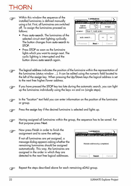
Within this window the sequence of the installed luminaires is defined manually using a list. First, all luminaires are switched off. To assign the luminaires proceed as follows:• Press auto-search. The luminaires of the
selected circuit start lighting cyclically. The button changes from auto-search to STOP.
• Press STOP as soon as the luminaire lights which you want to assign next. The cyclic lighting is interrupted and the button shows auto-search again.
The logical address indicates the position of the luminaire within the representation of the luminaires (status window ...). It can be edited using the numeric field located to the left of the assign key. When pressing the Up/Down keys the logical address is set to the next free higher/lower address.
If you have pressed the STOP key too late during the automatic search, you can light up the luminaires individually using the keys << and >> (single steps).
In the "location" text field you can enter information on the position of the luminaire or group.
Press the assign key if the desired luminaire is selected and lights up.
Having assigned all luminaires within the group, the sequence has to be saved. For that purpose press Next.
Now press Finish in order to finish the assignment and to save the settings.
If not all luminaires are yet assigned, a message dialog appears asking whether the remaining luminaires should be assigned automatically. This way, the luminaires are assigned in the order in which they are detected to the next free logical addresses.
Repeat the steps described above for each remaining eDALI group.

LUXMATE Explorer Project 23
4.4.2 Luminaires settings
Notes
Among other settings, the operation modes "Maintained" or "Non-maintained" are determined in the "Settings" menu.The display of the luminaires is identical to the display in the "Status" menu (see section 7.2 on page 32).
You have two possibilities to set up luminaires:
All luminaires within a group or each luminaire individually. To set up only one luminaire press the corresponding luminaire symbol. If all luminaires within a group should have the same values, press the reference text (e.g. Group1).
The first line shows the group name and the luminaire to be edited (or "all luminaires" if you have selected the complete group).• Test: Using this key you can check
luminaires. It is also helpful when locating individual luminaires. The appropriate luminaire (or all luminaires of the selected group) are switched off while the test key is pressed.
• locate start/stop: Using this key the location mode can be started and terminated. The luminaire is periodically switched on and off every 2 seconds.
• Location, Lamp Type, Info: Here you can enter useful information on the luminaires.

24 LUXMATE Explorer Project
5 Basic display
5.1 OverviewThe basic display shows the following information:1 Date and time.2 Device name (user definable).3 Status of the monitored luminaires.4 OK or failure info (result of last duration test
or function test).5 Symbolic representation of external devices
(GSM module, printer).
The device name can be defined by the user in order to distinguish several devices (Explorer Project XP128).
This designation is also transmitted when sending a SMS.
It is set in the "Options" menu.
5.2 DisplayLine 1 shows the current date and time. The date and time values can be edited using the "Options" item in the "Configuration" menu.
Line 2 indicates the device name.
Line 3 shows the result of the last function test or duration test or the current system operation mode: System disabled, Function test running, Duration test running.
In line 4 an error message is shown if failures occurred during the last function test or duration test. The test logs can then be viewed in the test book.
Line 5 displays the symbols of the connected devices:
Printer
GSM module The number of bars indicates the signal strength (max. 5 bars).
1
2
34
5

LUXMATE Explorer Project 25
5.3 Touch panel keys
5.4 Block system (quick menu)Executing this function disables the system by sending a blocking command to all luminaires via the eDALI bus.
Block system Pressing this key blocks the luminaires of the selected groups and the display shows the start screen. The red LED "Fault" is then flashing.
Enable system Pressing this key enables the luminaires of the selected groups and the display shows the start screen. The red LED "Fault" stops flashing.
Pressing this key leads from the basic menu to the quick menu, and from there to the menu selection. In the menu selection this key can be used to select the tabs and the menus of the individual submenus.
The quick menu enables a fast and comfortable access on the functions:• BLOCK system,• Start function test and• Start duration test.
If failures occurred, the info key directly opens the test book. Here, details concerning the error reason and for locating the defective luminaire can be found.
The help key calls an info page related to the Explorer Project XP128. From here, you can access the help main menu.

26 LUXMATE Explorer Project
NotesBlocked luminaires do not switch to emergency mode in the event of a power fail!
All other commands are inactive while the system is blocked.
After disabling (blocking) the system, the blocking command is transmitted periodically via the eDALI bus in order to keep these luminaires blocked which have had a power fail during blocking state (otherwise the emergency ballasts would leave the blocking state as soon as supply voltage is available again).
5.5 Start function test (quick menu)This command starts a manual function test (see section 6.3 on page 28).
Start function test Pressing this key starts the test and the display changes to the start screen indicating the progress of the test.
Cancel function test Pressing this key terminates the test and the display shows the start screen.
NoteAll other quick menu commands are inactive while the function test is running.
5.6 Start duration test (quick menu)This function starts a manual duration test (see section 6.4 on page 29).
The duration test may not be started until all emergency luminaires have been connected and the battery has been charged for at least 20 hours!
Start duration test Pressing this key starts the test and the display changes to the start screen indicating the progress of the test.
Cancel duration test Pressing this key terminates the test and the display shows the start screen.
NotesAll other quick menu commands are inactive while the duration test is running.
If the duration test can not be started for a luminaire (because the accumulator has not been charged), the systems re-initiates a further duration test on the next day at the same time. This cycle is repeated again on the following day. If the duration test then still reports a negative result, it will be stored and the status will be set.
LUXMATE Explorer Project 27
6 Test functions
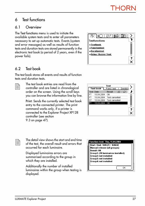
6.1 OverviewThe Test functions menu is used to initiate the available system tests and to enter all parameters necessary to set up automatic tests. Events (system and error messages) as well as results of function tests and duration tests are stored permanently in the electronic test book (a period of 2 years, even if the power fails).
6.2 Test bookThe test book stores all events and results of function tests and duration tests.
The test book entries are read from the controller and are listed in chronological order on the screen. Using the scroll keys you can browse the information line by line.
Print: Sends the currently selected test book entry to the connected printer. The print command works only, if a printer is connected to the Explorer Project XP128 controller (see section9.3 on page 47).
The detail view shows the start and end time of the test, the overall result and errors that occurred for each luminaire.
Displayed luminaires errors are summarised according to the group in which they are installed.
Additionally the number of installed luminaires within the group when testing is displayed.

28 LUXMATE Explorer Project
6.3 Function testThe function test checks luminaires during mains operation. You can program the desired time and day for an automatic execution of the function test for each group individually or for all groups at the same time. It is recommended to start the function test manually when initially commissioning the system or after new components have been added to the Explorer Project system or if other modifications have been made to the emergency lighting system (such as replacement of luminaires, configuration changes).
NoteNo automatic function test can be executed while the system is blocked or if the test is still running (e.g. after starting it manually). In this case the automatic test is delayed one day (until the set time of day is matching). An error message appears when attempting to start the test manually while the system is blocked.
Starting the function test
Group selection: All groups at the same time or each group individually.
start function test now: Press this key to immediately start the function test (duration: approx. 2 minutes).
Weekdays: Press the "Weekdays" field and select the desired day by marking the corresponding checkbox.
Time: Press the "Time" field and edit the value using the provided arrow keys.
Result of last function test displays the time, date and result of the last function test.
also see test book: View the last function test entry by pressing this key (see test book).

LUXMATE Explorer Project 29
Function test started
The following information is displayed while the function test is running:• Start date and time.• Type of activation:
"Manual release": manual test."Program": automatic test.
• Progress of the running function test (indicated in hours and minutes).
Cancel test
Press this key to abort the running function test.
6.4 Duration testDuring the duration test the batteries of all connected luminaires are discharged until the nominal operating time (between 1 and 3 hours, depending on the battery type) has elapsed. If the nominal operation time can not be reached, the error message "Battery fault" appears. The test is executed as long as the nominal operation time or the permissible limit operation time of the battery is exceeded (cut-off voltage reached or deep-discharging protection activated) or until the test is aborted manually.
You can program a day, the desired months and the time of day for the automatic test execution (e.g. at 11:00 pm on the 15th day in January, April, July and October).
NotePerform the duration test only outside of normal working hours and ensure that the batteries are re-charged in time before operation starts again (time of minimal risk).

30 LUXMATE Explorer Project
Starting the duration test
Group selection: The duration test can be started for all groups at the same time or for each group individually. Furthermore you can differentiate between even numbered and odd numbered luminaires.
Day, months: Press the "Day, months" field, select the day using the arrow keys and the month(s) by marking the checkbox(es).
Time: Press the "Time" field and edit the value using the provided arrow keys.
start duration test now: Press this key to immediately start the duration test. Depending on the nominal operation time the test may last up to three hours.
Result of last duration test: Shows the time, date and result of the last duration test.
also see test book: View the last duration test entry by pressing this key (see test book).
Duration test started
The following information is displayed while the duration test is running:• Start date and time.• Type of activation:
"Manual release": manual test."Program": automatic test.
• Progress of the running duration test (indicated in hours and minutes).
Cancel test
Press this key to abort the running duration test.
Note
The function test and/or the duration test can be programmed overlapping individual groups.It is not possible to overlap the duration test of even and odd numbered luminaires within one group.

LUXMATE Explorer Project 31
6.5 Relay / buzzer testThis menu shows the current status of the relay contacts. For test purposes, the status of the relays can be changed manually (to test a remote display, for example), and the tone of the buzzer and the fault light (red LED) can be checked.
By pressing or the controller immediately changes the switching status of the selected relay. The buzzer and failure light are switched on or off accordingly.
NoteAll relays return to the normal setting when exiting the menu.
32 LUXMATE Explorer Project
7 Luminaires
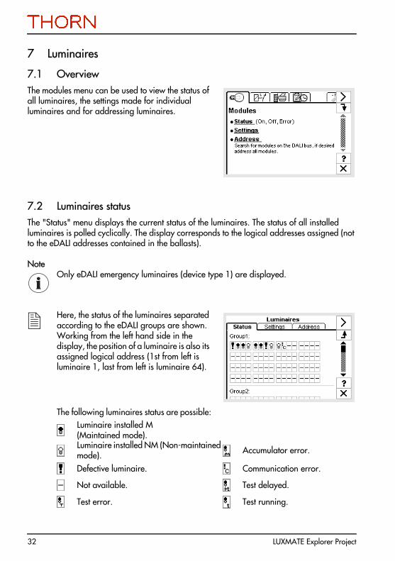
7.1 OverviewThe modules menu can be used to view the status of all luminaires, the settings made for individual luminaires and for addressing luminaires.
7.2 Luminaires statusThe "Status" menu displays the current status of the luminaires. The status of all installed luminaires is polled cyclically. The display corresponds to the logical addresses assigned (not to the eDALI addresses contained in the ballasts).
NoteOnly eDALI emergency luminaires (device type 1) are displayed.
Here, the status of the luminaires separated according to the eDALI groups are shown. Working from the left hand side in the display, the position of a luminaire is also its assigned logical address (1st from left is luminaire 1, last from left is luminaire 64).
The following luminaires status are possible:Luminaire installed M(Maintained mode).Luminaire installed NM (Non-maintained mode). Accumulator error.
Defective luminaire. Communication error.
Not available. Test delayed.
Test error. Test running.

LUXMATE Explorer Project 33
7.3 Luminaires settingsIn the "Settings" menu additional information (location, info text) can be assigned to luminaires. Using the command "Test" the status of the luminaire can be checked immediately.
NotesThe assignment of the luminaires must be completed before defining the luminaires settings (see section 7.4 on page 34).
Additionally the operation mode is set to "Maintained mode" or "Non-maintained
mode" .
The display of the luminaires is identical to the display in the "Status" menu (see section 7.2 on page 32).
You have two ways of setting up luminaires:
All luminaires of a group (overwrites already existing settings of all luminaires within the selected group) or each luminaire individually.
To set up only one luminaire press the corresponding luminaire symbol. If all luminaires within a group should have the same values, press the reference text (e.g. Group1).
34 LUXMATE Explorer Project
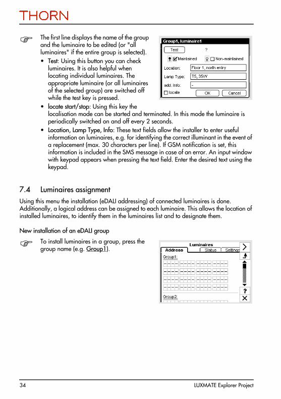
The first line displays the name of the group and the luminaire to be edited (or "all luminaires" if the entire group is selected).• Test: Using this button you can check
luminaires. It is also helpful when locating individual luminaires. The appropriate luminaire (or all luminaires of the selected group) are switched off while the test key is pressed.
• locate start/stop: Using this key the localisation mode can be started and terminated. In this mode the luminaire is periodically switched on and off every 2 seconds.
• Location, Lamp Type, Info: These text fields allow the installer to enter useful information on luminaires, e.g. for identifying the correct illuminant in the event of a replacement (max. 30 characters per line). If GSM notification is set, this information is included in the SMS message in case of an error. An input window with keypad appears when pressing the text field. Enter the desired text using the keypad.
7.4 Luminaires assignmentUsing this menu the installation (eDALI addressing) of connected luminaires is done. Additionally, a logical address can be assigned to each luminaire. This allows the location of installed luminaires, to identify them in the luminaires list and to designate them.
New installation of an eDALI group
To install luminaires in a group, press the group name (e.g. Group1).

LUXMATE Explorer Project 35
Now, you can select between:• System extension: Adding one or several
luminaires without discarding the existing luminaires’ addressing and info texts.
• Reinitialization: New addressing of all luminaires connected to the particular group. When selecting this option, assigned luminaires are deleted and re-assigned.
After selecting "System extension" the systems checks the current luminaires installation before the actual search. All luminaires installed at the bus are searched.
Additionally it is checked whether luminaires with valid addresses are installed at the bus but not available in the Explorer Project XP128 controller list. If such luminaires are found they are added automatically.
The Explorer Project XP128 now searches for connected luminaires at the selected (eDALI) group and displays the number of new detected luminaires. The system distinguishes between (eDALI) emergency luminaires and other luminaires.

36 LUXMATE Explorer Project
Selection of the assignment method
Select the assignment method:• Optical search method/GSM:
A logical address can be assigned manually to each detected luminaire. If desired, this assignment can be defined via the GSM module using a mobile phone (refer to section 9.2 on page 44).
Click on Next to perform the luminaires assignment using the selected method. Having selected "Optical search method/GSM", the next window appears (see below).
Within this window the sequence of the installed luminaires is defined manually using a list. First, all luminaires are switched off. To assign the luminaires proceed as follows:• Press auto-search. The luminaires of the
selected group start lighting cyclically. The button changes from auto-search to STOP.
• Press STOP as soon as the luminaire lights which you want to assign next. The cyclic lighting is interrupted and the button shows auto-search again.
The logical address indicates the position of the luminaire within the representation of the luminaires (status window ...). It can be edited using the numeric field located to the left of the assign key. When pressing the Up/Down keys the logical address is set to the next free higher/lower address.
If you have pressed the STOP key too late during the automatic search, you can light up the luminaires individually using the keys << and >> (single steps). It is possible to define the sequence using these keys in general, i.e. without using the automatic search.
In the "location" text field you can enter information on the position of the luminaire.

LUXMATE Explorer Project 37
Press the assign key if the desired luminaire is selected and lights up. The luminaire is inserted into the list with the selected logical address. This position is displayed on the left of the assign key.
In the figure shown above, pressing the assign key would insert the luminaire into the list as first luminaire. Then, the next free logical address is displayed. Repeat these steps for all remaining luminaires until all are arranged in the desired order.
Having assigned all luminaires within the group, the sequence has to be saved. For that purpose press Next.
Now press Finish in order to finish the assignment and to save the settings.
If all luminaires are not yet assigned, a message dialog appears asking whether the remaining luminaires should be assigned automatically. This way, the luminaires are assigned in the order in which they are detected to the next free logical addresses.
Repeat the steps described above for each remaining (eDALI) group.

38 LUXMATE Explorer Project
7.5 Setting up groups with Explorer Project Extender
NotesA maximum of 3 Explorer Project Extender modules can be connected to the eDALI bus (terminals B-D1, B-D2). The eDALI bus A (terminals A-D1, A-D2) is not designed to connect Explorer Project Extender modules. If a Explorer Project Extender module is connected to eDALI bus B (i.e. terminals B-D1, B-D2), all luminaires which are connected to this bus can only be accessed via this Explorer Project Extender module.
It is not allowed to connect luminaires and Explorer Project Extender modules to the eDALI bus B (terminals B-D1, B-D2).
New installation of an eDALI group
To install the Explorer Project Extender modules connected to the eDALI bus B, press one of the group names Group 2 - Group 4, e.g. Group2.
Use the scroll keys visible on the right hand of the screen to display the groups 2 to 4.
Similar to the "Luminaires assignment" menu you can now select between:• System extension or • Reinitialization.
After searching successfully, first none of the luminaires connected to the Explorer Project Extender modules are lighting.

LUXMATE Explorer Project 39
When assigning the individual Explorer Project Extenders, all luminaires connected to the selected Explorer Project Extender light.
There are no restrictions for the assignment of the group (Group 2 to 4) to a specific Extender.
Finishing the assignment.
After selecting "System extension" the system first checks the current luminaires installation before starting the search process. All luminaires installed at the bus are searched.
Once the search operation is completed, proceed as described in section 7.4 on page 34.
If an Explorer Project Extender is connected the additional key Extender is available.

40 LUXMATE Explorer Project
Pressing the Extender key calls the window shown here.• Delete: Deletes the Explorer Project
Extender permanently from the bus and from the list of the Explorer Project XP128.
• Replace extender: If an Explorer Project Extender at the bus has to be replaced by another due to a failure, its logical address can be applied to a new Extender.
• Resolve double address: Using this item, conflicts can be eliminated which are caused by double addressing of Extenders.
7.6 Assigning luminaires via GSM mobile phoneInstead of assigning luminaires using touch panel control keys, you can alternatively use a GSM mobile phone. Proceed as described above but use the mobile phone buttons for entering data.
Prerequisite for this method is that an Explorer Project GSM module (power supply XPPSU required) is connected to the Explorer Project XP128.
Prior to assigning the luminaires you have to dial the number of the GSM module using a tone-dialling mobile phone. Now you can control the assignment of luminaires using the phone buttons instead of using the touch panel.
The following mobile phone buttons correspond to the keys on the touch panel:
Touch panel Mobile phone
assign Button 1
Start / Stop Button 5
<< back Button 4
>> next Button 6

LUXMATE Explorer Project 41
NotesThe Explorer Project GSM module confirms the successful establishment of the connection by an automatic announcement. Additionally the green LED at the Explorer Project GSM module flashes.Setting up the luminaires has to be initiated at the Explorer Project XP128. Access via GSM phone is only possible while the assignment dialog is active. All other steps during the setup procedure have to be performed directly at the Explorer Project XP128.
7.7 Setting up single luminairesSelecting a single luminaire in the setup window (instead of an entire group as described in the previous section) calls the window shown here.• Delete: Deletes the luminaire
permanently from the bus and from the luminaires list of the Explorer Project XP128. The eDALI address stored in the ballast as well as the information stored in the Explorer Project XP128 luminaires list (parameters, info texts) are deleted too.
• Replace device: If a luminaire at the bus has to be replaced by another due to a failure, its settings can be applied to the new luminaire using this item. A system extension search is performed and then the assignment dialog is called for this logical address. The displayed logical address can not be edited while replacing.
• Resolve double address: Using this item, conflicts can be eliminated which are caused by two luminaires having the same (eDALI) address (this may happen when adding an already addressed luminaire). The conflict is reported in the form of a communication error in the status window. The selected luminaire(s) will be deleted, a system extension search is performed and then the assignment dialog is called for this single luminaire. All settings which already have been made for this luminaire are still valid.

42 LUXMATE Explorer Project
8 Error assignments to relays / buzzer / GSM
8.1 OverviewThis menu displays the current status of the relays. Various system states can be assigned to the relays, the buzzer or to messages via the Explorer Project GSM module.
8.2 StatusThis menu shows the current status of the relays with the floating signalling contacts.
8.3 AssignmentsThis menu is used to assign the system states, which only change due to an executed function test and duration test, to the signalling contacts of the relays, to the buzzer and for transmission to the GSM mobile network by means of SMS (Short Message Service). The relays switch from 'released' to 'operated' if a message assigned to a relay appears. In case of the buzzer, it sounds and in case of GSM an SMS message is sent to a GSM mobile phone.
Message types can be configured for the following system states:• Normal operation (during normal operation no test is running, no error exists).• Function test or duration test is currently running.• During the last test a lamp fault, battery fault or ballast fault occurred.• Communication problem on the (eDALI) bus.

LUXMATE Explorer Project 43
Assign the available messages to the desired message types by marking the appropriate checkboxes. The message types can be combined as desired for each message (from checking none to checking all). In this way a battery fault, for example, may activate a remote display via a relay, trigger the buzzer to sound and send a corresponding SMS.
Factory settings: Press this key to reset the message assignments to the factory settings (according to VDE 0801).
NoteWhen using a remote display for emergency lighting systems, pay attention to national guidelines and regulations.

44 LUXMATE Explorer Project
9 External devices
9.1 OverviewThis menu provides the possibility to configure optional components for the Explorer Project XP128.
9.2 Explorer Project GSM ModuleThe Explorer Project GSM module is designed as additional module for the Explorer Project XP128. It enables the communication between the Explorer Project XP128 and a standard telephone. Telephone conversation is possible via the built in microphone and speaker. Using the GSM module, Explorer Project XP128 can send messages (e.g. failure messages) to a mobile phone via SMS (Short Message Service). On the other hand, commands can be sent to the Explorer Project XP128 using the buttons of a tone-dialling telephone. (This is very useful when setting up luminaires, for example.)
In order to establish a connection to a mobile network, an activated SIM card has to be inserted into the GSM module. Detailed information about installing and commissioning the Explorer Project GSM module can be found in the relevant installation and operating instructions.
Version: Displays the version number of the GSM module.
Provider: Shows the provider.
On Error send SMS to: Press this field to enter a telephone number using the keypad. If configured accordingly (see section 7.2 on page 32), an SMS is sent to the entered number in the event of a failure.
Remote Access: 4-digit number for authentication of the GSM addressing (default setting: 0000).
Hands-free operation: Allows for example to speak with colleagues while installing.

LUXMATE Explorer Project 45
Volume: Press the Up/Down keys to adjust the volume. The current volume is indicated by bars.
Important phone numbers can be stored permanently in an address book.
Numbers can either be selected from this list or entered directly using the numeric keys.
To establish a connection, enter the desired number and then press the unhook key.
NoteIf the GSM connection is still established when pressing the "exit" key, the user is asked whether the connection should be maintained (e.g. for speaking with the colleague while assigning) or to hang up.
The Explorer Project XP128 continuously checks the state of the Explorer Project GSM module. If required, the following notes are displayed instead of the setup window shown above.
No GSM module connected: There is either no GSM module available or it is connected improperly (data lines, power supply). After removing the fault, you can attempt to establish the connection to the GSM module by pressing the OK key.
Basic display if no GSM module is connected.

46 LUXMATE Explorer Project
NotesEnsure that your provider supports SMS service and that the receiving telephone is able to receive SMS.Some SIM cards are protected by a PIN code. In this case you have to enter the PIN code via the controller.
Basic display if the PIN has not yet been entered.
Enter PIN: Press the "PIN code" field in order to enter the numeric SIM card code via the keypad. The code is displayed hidden (****).
LUXMATE Explorer Project 47
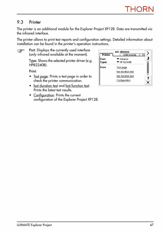
9.3 PrinterThe printer is an additional module for the Explorer Project XP128. Data are transmitted via the infrared interface.
The printer allows to print test reports and configuration settings. Detailed information about installation can be found in the printer's operation instructions.
Port: Displays the currently used interface (only infrared available at the moment).
Type: Shows the selected printer driver (e.g. HP82240B).
Print: • Test page: Prints a test page in order to
check the printer communication.• last duration test and last function test:
Prints the latest test results.• Configuration: Prints the current
configuration of the Explorer Project XP128.

48 LUXMATE Explorer Project
10 Device configuration
10.1 OverviewIn the "Configuration" menu the language of the user interface, date and time can be selected and the password protection can be activated.
10.2 OptionsThis menu is used to set the language, time and date.
Device-Infotext: Press the text in order to edit the device designation.
With the help of the device designation the Explorer Project XP128 can be distinguished. It is visible in the basic display and used within SMS messages.
Language: Press the options list and select the language for the user interface.
System Time, System Date: Press the appropriate value to set the time and date. A dialog field appears in which you can enter the desired values using arrow the keys.

LUXMATE Explorer Project 49
10.3 DisplayUsing the display settings, you can define the desired brightness and contrast and re-calibrate the touch panel coordinates.
Touch panel Clean: Press this key before cleaning the touch panel. The touch panel is deactivated for 20 seconds.
Touch panel Calibration: Pressing this key enables re-calibration of the touch panel coordinates. In the following dialog you have to press 3 target points (center, above left corner, bottom right corner) to finish the adjustment.
Beep on Touch: Check / uncheck this checkbox to activate or deactivate the beep on touching.
LCD contrast: Pressing the keys -- or ++ reduces/raises the display contrast. Changes are immediately visible.
10.4 ServiceSoftware Version: Displays the version number of the currently running software.
More options: A special password is required to access these options. During normal operation they are not required.

50 LUXMATE Explorer Project

51LU
XMA
TE E
xplo
rer
Proj
ect
11Er
ror
chec
k lis
ts fo
r th
e Ex
plor
er P
roje
ct s
yste
m
11.1
Usi
ng th
e er
ror
dete
ctio
n ta
bles
Proc
eed
as fo
llow
s w
hen
usin
g th
e er
ror
dete
ctio
n ta
bles
:1.
Det
erm
ine
the
mod
ule
of th
e lu
min
aire
.2.
Sear
ch th
e fir
st pr
oble
m d
escr
iptio
n co
lum
n fro
m th
e to
p to
the
botto
m fo
r co
rres
pond
ence
.3.
Isola
te th
e er
ror
by m
eans
of f
urth
er m
easu
rem
ents
and
chec
ks: S
earc
h th
e se
cond
pro
blem
des
crip
tion
colu
mn
from
the
top
to th
e bo
ttom
for
corr
espo
nden
ce.
4.Pe
rform
furth
er fa
ult i
sola
tion
if a
third
col
umn
is a
vaila
ble
in th
e pr
oble
m d
escr
iptio
n.5.
Elim
inat
e th
e er
ror
with
the
help
of t
he la
st co
lum
n.6.
If th
e er
ror
coul
d no
t be
rem
oved
go
thro
ugh
the
list a
gain
.

52LU
XMA
TE E
xplo
rer
Proj
ect
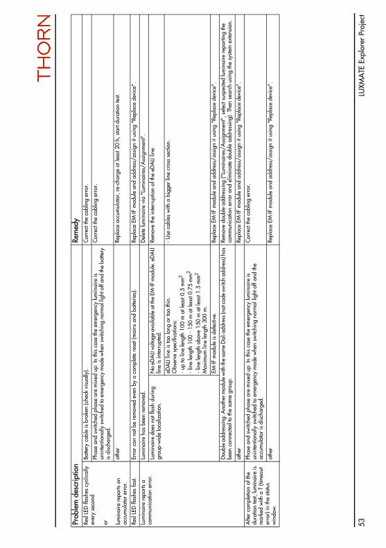
11.2
Erro
r de
tect
ion
for
emer
genc
y ex
it si
gn lu
min
aire
s /
secu
rity
lum
inai
res
with
EM
-IF M
odul
ePr
oble
m d
escr
iptio
nRe
med
yLu
min
aire
can
not
be
dete
cted
afte
r re
initi
alis
atio
n or
sys
tem
ex
tens
ion.
Lum
inai
re d
oes
not f
lash
dur
ing
grou
p-w
ide
loca
lizat
ion.
No
eDA
LI vo
ltage
ava
ilabl
e at
the
EM-IF
mod
ule.
eD
ALI
line
is in
terr
upte
d.Re
mov
e th
e in
terr
uptio
n of
the
eDA
LI lin
e.
eDA
LI lin
e is
too
long
or
too
thin
. O
bser
ve s
peci
ficat
ions
:- u
p to
line
leng
th 1
00 m
at l
east
0.5
mm
2
- lin
e le
ngth
100
- 15
0 m
at l
east
0.75
mm
2
- lin
e le
ngth
abo
ve 1
50 m
at l
east
1.5
mm
2
Max
imum
line
leng
th 3
00 m
.
- Use
cab
les
with
a b
igge
r lin
e cr
oss
sect
ion.
EM-IF
mod
ule
is d
efec
tive.
Repl
ace
EM-IF
mod
ule
and
re-a
ddre
ss/a
ssig
n it
usin
g th
e sy
stem
ext
ensi
on.
EM-IF
mod
ule
has
alre
ady
been
ad
dres
sed
but i
t has
the
sam
e ad
dres
s lik
e an
othe
r m
odul
e.
(dou
ble
addr
essi
ng).
Ano
ther
lum
inai
re in
dica
tes
a co
mm
unic
atio
n er
ror
in
the
statu
s w
indo
w a
fter
seve
ral m
inut
es a
t the
late
st.Re
mov
e do
uble
add
ress
ing
("Lu
min
aire
s/A
ssig
nmen
t", s
elec
t sus
pect
ed lu
min
aire
rep
ortin
g th
e co
mm
unic
atio
n er
ror
and
elim
inat
e do
uble
add
ress
ing)
. The
n se
arch
usi
ng th
e sy
stem
ext
ensi
on.
othe
rTh
ere
are
seve
ral f
urth
er p
ossi
bilit
ies
for
elim
inat
ing
a do
uble
add
ress
ing:
- Com
plet
e gr
oup
re-in
itial
izat
ion.
- Dis
conn
ect t
he D
ali l
ine
and
conn
ect t
he s
uspe
cted
lum
inai
re d
irect
ly to
the
XP12
8 or
Ext
ende
r re
spec
tivel
y. A
fter a
sho
rt tim
e al
l lum
inai
res
exce
pt o
ne s
houl
d re
port
a co
mm
unic
atio
n er
ror i
n th
e sta
tus
win
dow
. Del
ete
this
lum
inai
re ("
Lum
inai
res/
Ass
ignm
ent"
, sel
ect s
uspe
cted
lum
inai
re
and
dele
te it
). C
orre
ct th
e ca
blin
g an
d ad
dres
s/as
sign
the
mis
sing
lum
inai
res
afte
rwar
ds v
ia th
e sy
stem
ext
ensi
on.
- Use
ano
ther
EM
-IF m
odul
e an
d re
-add
ress
/ass
ign
it vi
a th
e sy
stem
ext
ensi
on.
No
supp
ly v
olta
ge a
vaila
ble
at th
e EM
-IF m
odul
e.C
orre
ct th
e ca
blin
g er
ror.
othe
rRe
plac
e EM
-IF m
odul
e an
d re
-add
ress
/ass
ign
it us
ing
the
syste
m e
xten
sion
.
Red
LED
ligh
ts pe
rman
ently
or lum
inai
re r
epor
ts fa
ulty
ill
umin
ant.
Illum
inan
t is
defe
ctiv
e. D
etec
tion:
- Rec
omm
ende
d: b
y m
easu
ring
the
resi
stanc
e of
bot
h ca
thod
es (a
ppro
x. 1
0 O
hm),
- Vis
ually
due
to b
lack
col
orat
ion,
- Em
piric
ally
by
repl
acem
ent.
Repl
ace
illum
inan
t and
per
form
func
tion
test.
Vis
ually
che
ck th
e ca
blin
g to
war
ds th
e ill
umin
ant h
olde
rs.
Cor
rect
the
cabl
ing
erro
r.
othe
rRe
plac
e EM
-IF m
odul
e an
d ad
dres
s/as
sign
it u
sing
"Re
plac
e de
vice
".
53LU
XMA
TE E
xplo
rer
Proj
ect
Red
LED
flas
hes
cycl
ical
ly
ever
y se
cond
or lum
inai
re r
epor
ts an
ac
cum
ulat
or e
rror
.
Batte
ry c
able
is b
roke
n (c
heck
vis
ually
).C
orre
ct th
e ca
blin
g er
ror.
Phas
e an
d sw
itche
d ph
ase
are
mix
ed u
p: In
this
cas
e th
e em
erge
ncy
lum
inai
re is
un
inte
ntio
nally
sw
itche
d to
em
erge
ncy
mod
e w
hen
switc
hing
nor
mal
ligh
t off
and
the
batte
ry
is d
isch
arge
d.
Cor
rect
the
cabl
ing
erro
r.
othe
rRe
plac
e ac
cum
ulat
or, r
e-ch
arge
at l
east
20 h
, sta
rt du
ratio
n te
st.
Red
LED
flas
hes
fast.
Erro
r ca
n no
t be
rem
oved
eve
n by
a c
ompl
ete
rese
t (m
ains
and
bat
terie
s).
Repl
ace
EM-IF
mod
ule
and
addr
ess/
assi
gn it
usi
ng "
Repl
ace
devi
ce".
Lum
inai
re r
epor
ts a
com
mun
icat
ion
erro
r.Lu
min
aire
has
bee
n re
mov
ed.
Del
ete
lum
inai
re v
ia "
Lum
inai
res/
Ass
ignm
ent"
.
Lum
inai
re d
oes
not f
lash
dur
ing
grou
p-w
ide
loca
lizat
ion.
No
eDA
LI vo
ltage
ava
ilabl
e at
the
EM-IF
mod
ule.
eD
ALI
line
is in
terr
upte
d.Re
mov
e th
e in
terr
uptio
n of
the
eDA
LI lin
e.
eDA
LI lin
e is
too
long
or
too
thin
. O
bser
ve s
peci
ficat
ions
:- u
p to
line
leng
th 1
00 m
at l
east
0.5
mm
2
- lin
e le
ngth
100
- 15
0 m
at l
east
0.75
mm
2
- lin
e le
ngth
abo
ve 1
50 m
at l
east
1.5
mm
2
Max
imum
line
leng
th 3
00 m
.
- Use
cab
les
with
a b
igge
r lin
e cr
oss
sect
ion.
EM-IF
mod
ule
is d
efec
tive.
Repl
ace
EM-IF
mod
ule
and
addr
ess/
assi
gn it
usi
ng "
Repl
ace
devi
ce".
Dou
ble
addr
essi
ng: A
noth
er m
odul
e w
ith th
e sa
me
Dal
i add
ress
(not
cod
e sw
itch
addr
ess)
has
be
en c
onne
cted
to th
e sa
me
grou
p.Re
mov
e do
uble
add
ress
ing
("Lu
min
aire
s/A
ssig
nmen
t", s
elec
t sus
pect
ed lu
min
aire
rep
ortin
g th
e co
mm
unic
atio
n er
ror
and
elim
inat
e do
uble
add
ress
ing)
. The
n se
arch
usi
ng th
e sy
stem
ext
ensi
on.
othe
rRe
plac
e EM
-IF m
odul
e an
d ad
dres
s/as
sign
it u
sing
"Re
plac
e de
vice
".
Afte
r co
mpl
etio
n of
the
dura
tion
test,
lum
inai
re is
m
arke
d w
ith a
T (t
imeo
ut
erro
r) in
the
statu
s w
indo
w.
Phas
e an
d sw
itche
d ph
ase
are
mix
ed u
p: In
this
cas
e th
e em
erge
ncy
lum
inai
re is
un
inte
ntio
nally
sw
itche
d to
em
erge
ncy
mod
e w
hen
switc
hing
nor
mal
ligh
t off
and
the
accu
mul
ator
is d
isch
arge
d.
Cor
rect
the
cabl
ing
erro
r.
othe
rRe
plac
e EM
-IF m
odul
e an
d ad
dres
s/as
sign
it u
sing
"Re
plac
e de
vice
".
Prob
lem
des
crip
tion
Rem
edy