Embed Size (px)
Citation preview

XP-400
Installation Instructions
Control Panel/Communicator
WI853C 8/97© NAPCO 1997
®
Wi853c page 1
Tuesday, September 16, 1997 10:42
2
WI853C XP-400 Installation Instructions
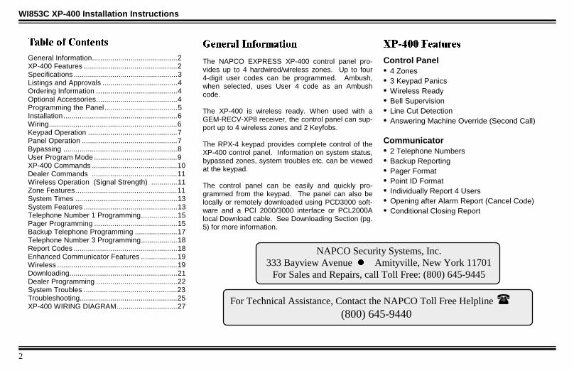
*HQHUDO ,QIRUPDWLRQ
The NAPCO EXPRESS XP-400 control panel pro-vides up to 4 hardwired/wireless zones. Up to four4-digit user codes can be programmed. Ambush,when selected, uses User 4 code as an Ambushcode.
The XP-400 is wireless ready. When used with aGEM-RECV-XP8 receiver, the control panel can sup-port up to 4 wireless zones and 2 Keyfobs.
The RPX-4 keypad provides complete control of theXP-400 control panel. Information on system status,bypassed zones, system troubles etc. can be viewedat the keypad.
The control panel can be easily and quickly pro-grammed from the keypad. The panel can also belocally or remotely downloaded using PCD3000 soft-ware and a PCI 2000/3000 interface or PCL2000Alocal Download cable. See Downloading Section (pg.5) for more information.
;3 )HDWXUHV
Control Panel• 4 Zones• 3 Keypad Panics• Wireless Ready• Bell Supervision• Line Cut Detection• Answering Machine Override (Second Call)
Communicator• 2 Telephone Numbers• Backup Reporting• Pager Format• Point ID Format• Individually Report 4 Users• Opening after Alarm Report (Cancel Code)• Conditional Closing Report
For Technical Assistance, Contact the NAPCO Toll Free Helpline (800) 645-9440
NAPCO Security Systems, Inc.333 Bayview Avenue z Amityville, New York 11701
For Sales and Repairs, call Toll Free: (800) 645-9445
7DEOH RI &RQWHQWV
General Information..........................................2XP-400 Features ..............................................2Specifications ...................................................3Listings and Approvals .....................................4Ordering Information ........................................4Optional Accessories........................................4Programming the Panel....................................5Installation........................................................6Wiring...............................................................6Keypad Operation ............................................7Panel Operation ...............................................7Bypassing ........................................................8User Program Mode .........................................9XP-400 Commands ..........................................10Dealer Commands ..........................................11Wireless Operation (Signal Strength) .............11Zone Features ..................................................11System Times ..................................................13System Features ..............................................13Telephone Number 1 Programming..................15Pager Programming .........................................15Backup Telephone Programming .....................17Telephone Number 3 Programming..................18Report Codes ...................................................18Enhanced Communicator Features ..................19Wireless ...........................................................19Downloading.....................................................21Dealer Programming ........................................22System Troubles ..............................................23Troubleshooting................................................25XP-400 WIRING DIAGRAM..............................27
Wi853c page 2
Tuesday, September 16, 1997 10:42
3
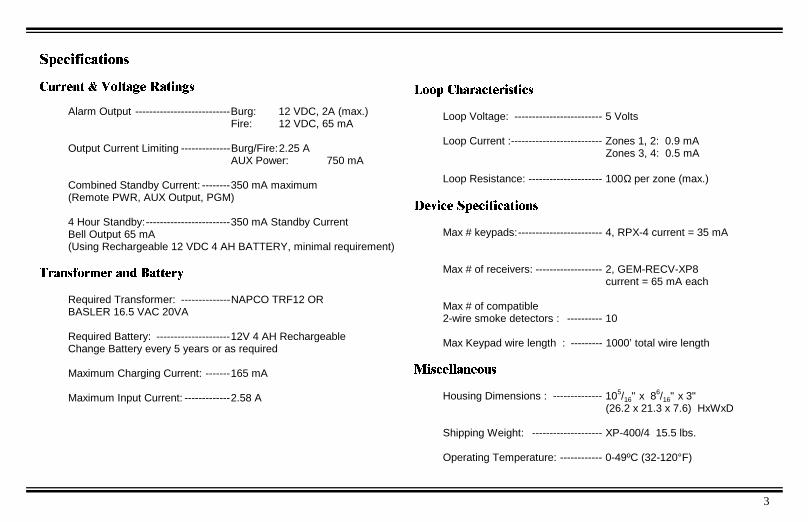
6SHFLILFDWLRQV
&XUUHQW 9ROWDJH 5DWLQJV
Alarm Output ---------------------------Burg: 12 VDC, 2A (max.)Fire: 12 VDC, 65 mA
Output Current Limiting --------------Burg/Fire:2.25 AAUX Power: 750 mA
Combined Standby Current: --------350 mA maximum(Remote PWR, AUX Output, PGM)
4 Hour Standby:------------------------350 mA Standby CurrentBell Output 65 mA(Using Rechargeable 12 VDC 4 AH BATTERY, minimal requirement)
7UDQVIRUPHU DQG %DWWHU\
Required Transformer: --------------NAPCO TRF12 ORBASLER 16.5 VAC 20VA
Required Battery: ---------------------12V 4 AH RechargeableChange Battery every 5 years or as required
Maximum Charging Current: -------165 mA
Maximum Input Current: -------------2.58 A
/RRS &KDUDFWHULVWLFV
Loop Voltage: ------------------------- 5 Volts
Loop Current :-------------------------- Zones 1, 2: 0.9 mAZones 3, 4: 0.5 mA
Loop Resistance: --------------------- 100Ω per zone (max.)
'HYLFH 6SHFLILFDWLRQV
Max # keypads:------------------------ 4, RPX-4 current = 35 mA
Max # of receivers: ------------------- 2, GEM-RECV-XP8current = 65 mA each
Max # of compatible2-wire smoke detectors : ---------- 10
Max Keypad wire length : --------- 1000’ total wire length
0LVFHOODQHRXV
Housing Dimensions : -------------- 105/16" x 86/16" x 3"(26.2 x 21.3 x 7.6) HxWxD
Shipping Weight: -------------------- XP-400/4 15.5 lbs.
Operating Temperature: ------------ 0-49ºC (32-120°F)
Wi853c page 3
Tuesday, September 16, 1997 10:42

4
WI853C XP-400 Installation Instructions
4 zone Control PanelKeypadZone Doubling Resistors (2.2K & 3.9K)Operating Instructions XP-400Programming Instructions XP-400
XP-400RPX-4ZDROI220WI854C
2UGHULQJ ,QIRUPDWLRQ
/LVWLQJV DQG $SSURYDOV
UL HOUSEHOLD BURGLARY WARNING SYSTEM CONTROL UNITSTANDARDS # 1023, 985
VERIFIED TO COMPLY WITH F.C.C. PART 15 AS CLASS B : DIGITAL DEVICE
(XURSHDQ (0& 5HJXODWLRQV &( &HUWLILFDWLRQ
HARMONIZED STANDARDS: EN50081-1 and EN50082-1EC DIRECTIVES: 89/336/EEC, Electromagnetic Compatibility Directive
2SWLRQDO $FFHVVRULHV
*Wireless ReceiverWindow/Door TransmitterKey Fob TransmitterWireless PIRWireless Dual-Technology SensorWireless Glass-Break DetectorRelay BoardAudio Verification ModuleDownloading Software for IBM PC CompatiblesSoftware with Interface for IBM PC Compatibles(Includes PCL2000A local download cable)Local Download cable
GEM-RECV-XP8:GEM-TRANS2GEM-KEYF:GEM-PIR:GEM-DT:GEM-GB:RB1000Veriphone:PCD3000:PCI2000/3000:
PCL2000A
*Supports up to 8 zones, 4 Key Fobs, 4 Smoke Detectors
Wi853c page 4
Tuesday, September 16, 1997 10:42

5
3URJUDPPLQJ WKH 3DQHORefer to XP-400 Programming Instructions (WI854C)
Defaulting the Panel
1. Remove power from the panel.2. Remove all wiring from terminal 15 (PGM)
and terminal 3.3. Connect terminal 15 (PGM) to terminal 3.4. Apply power to the XP-400 control panel.5. After a few seconds the ARMED, READY and*SYSTEM TROUBLE LEDs will flash.
6. The keypad will beep 3 times indicating thepanel default values have been loaded.
7. Remove wiring between terminal 15 (PGM)and terminal 3.
8. Re-install original wiring for terminal 15 (PGM)and terminal 3.
Keypad ProgrammingRefer to WI854C for information on keypad pro-gramming.
Downloading
The XP-400 panel can be download/uploadedwith PCD3000 software using the Ring Method,Answering Machine Override (Second Call) or Method of downloading. The panel can
also be automatically downloaded/uploaded us-ing PCD2000 Software running PCPreset. ForSite Initiated Downloaded, see Auto DownloadID Number [93].
Local Downloading
Wire as shown in Figure 1. Use the power up or method of establishing a connection. Thepower up method is recommended if the panel isattempting to report.
Remote Downloading
Wire as shown in Figure 2. The panel canbe remotely download/uploaded using anyone of the following methods:1. The method2. Call-in method
3. Answering Machine Override (Second Call)4. Site-Initiated (PCPreset & )5. Automatic Downloading (Using PCPreset)
PGM(-)
+12 -13 14 15 16 17 18 19+PWR GND GREEN TIP RING
PHONE
PCL2000A
GREENRED
MODEM
FIGURE 1 LOCAL DOWNLOAD
TIP RING
TELCO
MODEM
J1TO COMPUTER
J3LOCAL
TO
PCI2000
J2TO EXTERNAL
MODEM
J4TELCO
J5 LINEOUT TO
TELCO
FIGURE 2 REMOTE DOWNLOAD
PGM(-)
+12 -13 14 15 16 17 18 19+PWR GND GREEN
PHONETELCO
GREENRED
XP-400 Panel at the site
RING TIP RING
RJ31X
TIP
GRY
BRN
BLACKRED
NOTE:
Any programming in Dealer Options 1 [96] and DealerOptions 2 [97] will not be defaulted. If Dealer CodeLockout has been programmed the panel will not defaultthe Dealer Code.
Wi853c page 5
Tuesday, September 16, 1997 10:42

6
WI853C XP-400 Installation Instructions
,QVWDOODWLRQ
Mounting the PanelMount the Panel close to an unswitched ACsource, a cold-water pipe ground, and a tele-phone line connection.
Mounting the KeypadA keypad should be located near an exit/entrydoor. To remove the keypad from the backplate,insert a small screwdriver into the slots at thebottom of the keypad. Pull up on the screwdriverto pop off the cover.
Up to 3 keypads can be connected on individualwire runs with #22 AWG wire with a maximumtotal cable length of 1000 feet. Each keypaddraws approximately 35 mA.
:LULQJ
Grounding the PanelConnect the control-panel EARTH GROUNDscrew to a metal cold-water pipe. Do not use agas pipe, plastic pipe or AC ground connec-tions. Use at least #16 AWG wire. Connect awire with a ground lug crimped or soldered ontoone end and connect it to the EARTHGROUND screw in the cabinet.
AC Power and Battery WiringComplete all wiring before connecting the bat-tery or AC Power. Do not plug the transformerinto a switched outlet.
Telephone WiringWire as shown in the wiring diagram in the backof this manual.
WARNINGThe FCC restricts the use of this equipment oncertain telephone lines. Read the FCC state-ment on the back of this manual to ensurecompliance.
Burglary Zone Wiring
NAPCO’s EZ Zone DoublingTM is simple. Eachterminal has 2 zones, use an E (2.2 K) type
Zone Doubling Resistor for the primary zone anda Z (3.9 K) type Zone Doubling Resistor for thesecondary zone.
Wire zones as shown in the wiring diagram (pg.27). All resistors must be installed, even if thezone is not used. If required, unsupervised opencircuit devices may be used instead of closedcircuit devices. Program the zone as an OpenCircuit Zone [06] (Zone Doubling Resistor re-quired). If necessary, use the voltage chartbelow to verify proper voltages.
Terminals Primary Secondary3&4 Zone 1 Zone 3
5&4 Zone 2 Zone 4
TABLE 2 EZ ZONE DOUBLINGTM
Primary and Secondary zones normal 1.9 V
Secondary open 2.5 V
Primary open 3.2 V
Primary and Secondary open 5.0 V
Primary and Secondary shorted (Sys. Trbl 7-Zone Trbl)
0.0 V
TABLE 3 VOLTAGE AT TERMINALS 3&4, 5&4, 6&7
Keypad Wire Color Control Panel Terminal
RED 12 (+PWR)
BLACK 13 (GND)
GREEN 14 (GREEN)
TABLE 1 KEYPAD WIRING
Wi853c page 6
Tuesday, September 16, 1997 10:42
7
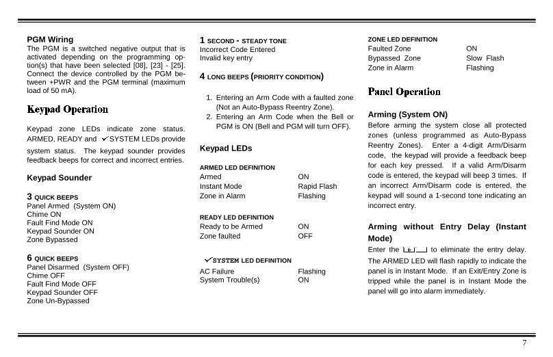
PGM WiringThe PGM is a switched negative output that isactivated depending on the programming op-tion(s) that have been selected [08], [23] - [25].Connect the device controlled by the PGM be-tween +PWR and the PGM terminal (maximumload of 50 mA).
.H\SDG 2SHUDWLRQ
Keypad zone LEDs indicate zone status.ARMED, READY andSYSTEM LEDs provide
system status. The keypad sounder providesfeedback beeps for correct and incorrect entries.
Keypad Sounder
3 QUICK BEEPSPanel Armed (System ON)Chime ONFault Find Mode ONKeypad Sounder ONZone Bypassed
6 QUICK BEEPSPanel Disarmed (System OFF)Chime OFFFault Find Mode OFFKeypad Sounder OFFZone Un-Bypassed
1 SECOND - STEADY TONEIncorrect Code EnteredInvalid key entry
4 LONG BEEPS (PRIORITY CONDITION)
1. Entering an Arm Code with a faulted zone(Not an Auto-Bypass Reentry Zone).
2. Entering an Arm Code when the Bell orPGM is ON (Bell and PGM will turn OFF).
Keypad LEDs
ARMED LED DEFINITIONArmed ONInstant Mode Rapid FlashZone in Alarm Flashing
READY LED DEFINITIONReady to be Armed ONZone faulted OFF
SYSTEM LED DEFINITION
AC Failure FlashingSystem Trouble(s) ON
ZONE LED DEFINITIONFaulted Zone ONBypassed Zone Slow FlashZone in Alarm Flashing
3DQHO 2SHUDWLRQ
Arming (System ON)Before arming the system close all protectedzones (unless programmed as Auto-BypassReentry Zones). Enter a 4-digit Arm/Disarmcode, the keypad will provide a feedback beepfor each key pressed. If a valid Arm/Disarmcode is entered, the keypad will beep 3 times. Ifan incorrect Arm/Disarm code is entered, thekeypad will sound a 1-second tone indicating anincorrect entry.
Arming without Entry Delay (InstantMode)Enter the to eliminate the entry delay.
The ARMED LED will flash rapidly to indicate thepanel is in Instant Mode. If an Exit/Entry Zone istripped while the panel is in Instant Mode thepanel will go into alarm immediately.
Wi853c page 7
Tuesday, September 16, 1997 10:42

8
WI853C XP-400 Installation Instructions
Arming/Disarming with a KeyfobThe system can be armed by pressing the
key, and disarmed by pressing the key on
the Keyfob. Zones programmed as Exit/EntryFollower Zones can be bypassed when the
or keys on the Keyfob have been pro-
grammed for Interior [81-82]. Zones pro-grammed as Home/Away with Delay Zones canbe armed regardless of the state of the Exit/EntryZones when the or keys on the Keyfob
have been programmed for Full Set [81-82]. Toarm the system with all zones protected pressthe key. Press and hold the or
key for 1.5s to fully set the system (The LED onthe Keyfob indicates the Keyfob is tranmitting thesignal). Program Keyfob/Keyswitch Chirp [23-4]for an audible indication of system arming anddisarming.
Arming Instant with a KeyfobThe panel can be ARMED INSTANT when the or keys on the Keyfob have been
programmed for Instant [81-82]. To arm thesystem with Instant protection press the
key, then press and hold the or key for
1.5s to arm the panel with INSTANT protection.
Arming/Disarming with a KeyswitchThe system can be armed/disarmed by using amomentary Keyswitch wired to Zone 4 . Pro-gram Keyfob/Keyswitch Chirp [23-4] for an au-dible indication of system arming and disarm-ing.
Disarming (System OFF)After entering the premises through an Exit/Entry Zone, the keypad will sound the EntryDelay Tone. Enter a valid Arm/Disarm code. Ifa valid Arm/Disarm code is entered, the keypadwill beep 6 times, indicating the panel has beendisarmed. The red Armed LED will go out. Ifan incorrect Arm/Disarm Code is entered, thekeypad will sound a 1-second tone, indicatingincorrect entry. Press the key and re-enter
the code.
Disarming after an Alarm (Alarm Memory)The armed LED and the zone(s) that causedthe alarm will be be flashing. Disarm the panel.The system is currently not detecting zonefaults or displaying system trouble. The
zone(s) that caused the alarm will continue to
flash. The Ready andSYSTEM TRBL LEDs
are out indicating:
The system is displaying Alarm Memory .
Press the key to clear Alarm Memory.
%\SDVVLQJ
Automatic BypassingHome/Away with Delay ZonesThis zone type has the following operation de-pending on whether an Exit/Entry Zone has beenviolated during the Exit Delay time.
HomeExit/Entry Zone is not violatedZones selected as Home/Away with DelayZones will be bypassed automatically.
Away with DelayE xit/Entry Zone is violatedZones selected as Home/Away with DelayZones will have a fixed 20-second entry de-lay when violated before an Exit/Entry Zone.
NOTE:
Faulted Keyswitch or silent 24 hour zones normally do notdisplay at the keypad. If a silent 24 hour zone orKeyswitch is faulted at the time of arming the faulted zonewill display only while the priority sound is ON.
Wi853c page 8
Tuesday, September 16, 1997 10:42

9
Full Setting the System with AutomaticBypassing - Home/Away with DelayZones
From the KeypadPress to return protection to Home/
Away with Delay Zones that have been auto-matically bypassed. Three minutes are al-lowed to walk through Exit/Entry and Exit/Entry Follower Zones.
Using A Keyfob (GEM-KF)All zones in the system can be armed re-gardless of the state of the Exit/Entry Zonewhen arming with a Keyfob and using anAUX key programmed as Full Set . Press and press and hold the or keys
for 1.5s when leaving the premises. Allzones, including Home/Away Zones arearmed.
Bypassing a zonePress the key, then the zone number to be
bypassed. While the panel is DISARMED, the
bypassed zone LED will flash slowly; indicatingthe zone has been bypassed. While the panelis ARMED, the bypassed zones will only bedisplayed if the Display Bypassed [21-3] optionhas been selected.
Unbypassing a zone (Disarmedonly)Press the key then the number of the
zone to be unbypassed.
Group BypassPress to Bypass all Exit/Entry
Follower Zones [02] or Home/Away Zones[01] (only if the system is programmedexclusively for Home/Away with Delayzones)..
Using A Keyfob (GEM-KF)Hold the or key on the Keyfob to
Bypass all Exit/Entry Follower Zones [02]or Home/Away Zones [01] (only if the sys-tem is programmed exclusively for Home/Away with Delay zones).
8VHU 3URJUDP 0RGH
To prevent the loss of the User 1 Code, the paneldefault program includes User 1 Code Lockout[96-2].To change the User 1 Code from its default valueof 1234, program the 4-digit User 1 Code throughDealer Programming [95]. User 1 Arm/Disarmcode is also used to program User Codes 2 - 4.By default, the User 1 code cannot be re-programmed by the user.If it is necessary to change the User 1 code, itcan be changed through downloading or Dealerkeypad programming. From Dealer ProgramMode, change the User 1 Code Lockout ([96-2]LED=OFF) to disabled.
Entering User Program Mode
1. Enter
2. Enter User 1 Code
()
(Default)
$50('
5($'<
6<67(0**
),5(
$&
Wi853c page 9
Tuesday, September 16, 1997 10:42

10
WI853C XP-400 Installation Instructions
While in User Program Mode the Armed, READYandSystem Trouble LEDs will continue toflash, follow the example below to program aUser 2’s code to 1923.
User Mode Programming Example:
1. Press , Zone 2 LED will Flash2. Enter , Zone 2 LED will
continue to flash until the 4th digit is entered.The keypad will beep 4 times confirming avalid entry (Zone LED steady).
Deleting a User CodePress the number of the User to be deleted, thezone LED will be flashing indicating that the userhas been selected. Press the , the LEDassociated with the user will now be OFF.
Exiting User Program ModeTo exit User Program Mode press the " key.
;3 &RPPDQGV
User Commands
Bell TestEnter this command to turn on the Bell, keypadsounder and keypad LEDs for 2 seconds. Thebattery is tested during a Bell Test, and auto-matically every *24 hours to ensure properbattery operation under load. The Alarm outputrequires a battery in order to supply the speci-fied output. If the battery cannot sustain theload, a low battery indication will be displayed.A battery test is also performed on power-upafter a 3 minute delay.
*A battery test occurs every 4 hours whenHousehold Fire [96-3] has been selected.
Group BypassEnter this command to bypass all Exit/EntryFollower Zones or Home/Away Zones (only ifthe system is programmed exclusively forHome/Away with Delay zones).
InstantEnter this command before or after arming toremove the entry delay on Entry/Exit Zones.The keypad ARMED LED will flicker rapidly.Faulting a Exit/Entry Zone will result in animmediate alarm.
Chime ON/OFFEnter this command to turn chime ON/OFF. TheKeypad will chime on any zone that has not beenselected as an Exit/Entry Follower Zone, Home/Away with Delay Zones, or 24 Hour Zone.
+ User 1 Code - User ProgramMode
Keypad Sleep Mode ON/OFFEnter this command to turn the keypad sounderON/OFF. When the keypad is in Sleep mode allkeypad sounds will be silenced except for key-pad feedback beeps and Keypad Sounder onAlarm.
User Commands - Optional
Easy Exit/Easy ArmIf enabled in Dealer programming, enter thiscommand while the panel is Armed to allow 3minutes to exit the premises through Exit/Entryand Exit/Entry Follower Zones. Enter ! toarm the panel. To disarm the panel a validArm/Disarm code must be entered. RequiresEasy Exit/Easy Arm [21-2] to be enabled.
Access on PGMIf enabled in Dealer programming, enter thiscommand to activate the PGM output (Terminal15) for 5 seconds.
Zone LED Meaning
OFF User Arm/Disarm Code not programmed
Flashing User Arm/Code is currently being programmed
Steady User Arm/Disarm Code has been programmed
TABLE 4 ZONE LED DEFINITION-USER PROGRAM MODE
Wi853c page 10
Tuesday, September 16, 1997 10:42

11
'HDOHU &RPPDQGV
Download (Programming Re-
quired)Establish a connection between the PCD phoneline and the Control Panel phone line. Whenready, tell the installer to arm, then disarm. Thenenter in order to establish a connection.
Phone connection to installer will go "dead" asdownloader and panel connect.
Fault Find ON/OFFHardwired Zone OperationEnter this command to turn Fault Find ON/OFF.While in Fault Find mode, the loop response forall zones will be set to the faster response of 40ms. The keypad will beep for .25-seconds whenhardwired zones are faulted and for 1-secondwhen zones are restored.
:LUHOHVV 2SHUDWLRQ
6LJQDO 6WUHQJWK
While in Fault Find mode the keypad will providean audible (Table 5) and visual (Figure 4) indica-tion of each transmitter’s signal strength. The
signal strength metering is based on a scale of4 to 10, with 4 being marginal and 10 beingexcellent.
The keypad will beep out a number, from 1-4,corresponding to the signal strength of thetransmitter. See Table 5 below. Each beep is1-second long. The keypad will sound a shortbeep for transmitters with signal strengths of 3or less.
=RQH )HDWXUHV
[00]Exit/Entry ZonesDelay allows exit and entry through an Exit/Entry Zone after the system is armed with-out setting off an immediate alarm. ExitDelay allows the user to leave the premisesafter arming. Entry Delay allows the usertime to enter and disarm. The entry delaymay be canceled by pressing !.
[01]Home/Away with Delay ZonesZones that automatically bypass at the expi-ration of the exit delay if the EXIT/ENTRYzone(s) are not violated. Zones of this typehave a three (3) minute power-up delay,and do not display or cause an alarm iffaulted when the system powers up. Press-ing the " key cancels the 3 minute timer.
If Exit/Entry zone(s) are violated during theexit delay, zones programmed as Home/Away with Delay Zone(s) will have a fixed20-second entry delay, if violated before theExit/Entry zone.
To eliminate this fixed 20-second entry de-
SIGNAL STRENGTH KEYPAD SOUNDER
3 or less .25S BEEP
4 BEEP
5 BEEP BEEP
6-7 BEEP BEEP BEEP
8-10 BEEP BEEP BEEP BEEP
TABLE 5 AUDIBLE SIGNAL STRENGTH INDICATION
FIGURE 4 VISUAL SIGNAL STRENGTH INDICATION
5 6-74 8-10
=21(
=21(
=21(
=21(
=21(
=21(
=21(
=21(
=21(
=21(
=21(
=21(
=21(
=21(
=21(
=21(
Wi853c page 11
Tuesday, September 16, 1997 10:42
12
WI853C XP-400 Installation Instructions
lay, also program zones as Exit/Entry Fol-lower Zones [02].To return protection to zones of this type,press #" from the keypad or or
from a Keyfob. Program the Keyfob AUX
1 or AUX 2 button for Full Set [81-7].
[02]Exit/Entry Follower ZonesEntry Delay allows the user time to enter anddisarm. Allows exit after the panel is armedwithout setting off an immediate alarm andallows entry only if an Exit/Entry Zone [00]has been violated first. Zones of this typehave a three (3) minute power-up delay, anddo not display or cause an alarm if faultedwhen the system powers up. Pressing the" key cancels the 3 minute timer.
Group Bypassing - Zones programmed asExit/Entry Follower Zones will be Group by-passed if the ## is pressed while
disarmed or within the Exit Delay.
Auto Interior Bypassing - Also programzones as Home/Away with Delay Zone(s) [01]to automatically bypass at the expiration of theexit delay if the EXIT/ENTRY Zone(s) are notviolated during the exit delay.
[03]Auto-Bypass Reentry ZonesZones programmed as this zone type arepermitted to be faulted at the time of arm-ing. Once the zone is restored, while thecontrol panel is still armed, the zone willautomatically be unbypassed and anysubsequent violations of the zone willcause an alarm condition.
[04]24-Hour ProtectionA zone that provides protection at all times,whether or not the system is armed.
[05]40 ms Loop ResponseNormally loop response is 750 ms, selectthis option to change the loop response to40 ms. The slower the loop response, theless sensitive the system will be to intermit-tents (swingers). The programming optionis not permitted for UL installations.
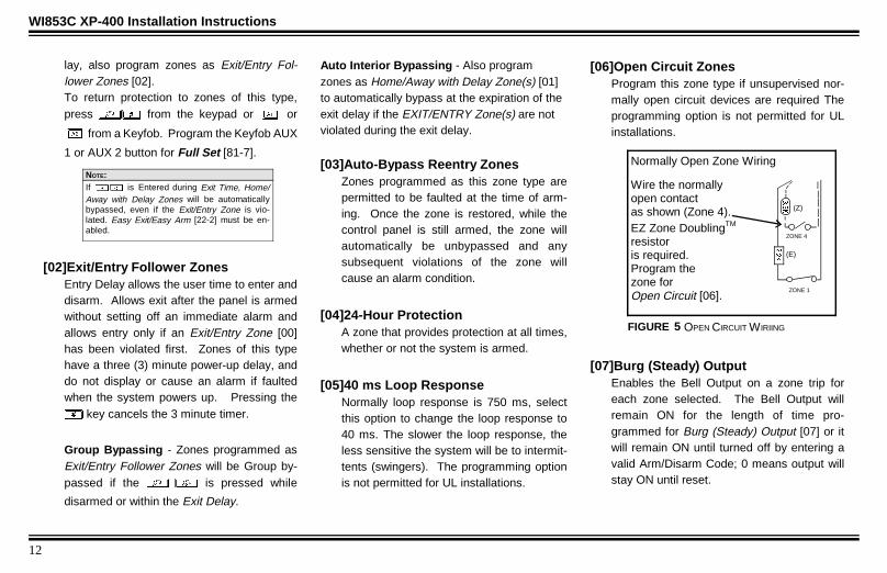
[06]Open Circuit ZonesProgram this zone type if unsupervised nor-mally open circuit devices are required Theprogramming option is not permitted for ULinstallations.
[07]Burg (Steady) OutputEnables the Bell Output on a zone trip foreach zone selected. The Bell Output willremain ON for the length of time pro-grammed for Burg (Steady) Output [07] or itwill remain ON until turned off by entering avalid Arm/Disarm Code; 0 means output willstay ON until reset.
If is Entered during Exit Time, Home/Away with Delay Zones will be automaticallybypassed, even if the Exit/Entry Zone is vio-lated. Easy Exit/Easy Arm [22-2] must be en-abled.
NOTE:Normally Open Zone Wiring
Wire the normallyopen contactas shown (Zone 4).EZ Zone DoublingTM
resistoris required.Program thezone forOpen Circuit [06].
(Z)
ZONE 1
(E)
.
ZONE 4
FIGURE 5 OPEN CIRCUIT WIRIING
.
Wi853c page 12
Tuesday, September 16, 1997 10:42

13
[08]PGM OutputEnables the PGM Output on a zone trip foreach zone selected. The PGM Output willremain ON until reset.
6\VWHP 7LPHV
[10]Exit DelayThe delay time which permits exit through anExit/Entry Zone [00] after the system isarmed, allows a user to leave the premiseswithout setting off an immediate alarm. ExitDelay may be programmed for up to 255seconds (4¼ minutes); a value of 0 defaultsto 60 seconds.
[11]Entry DelayDelay time permits entry through Exit/EntryZone(s) after the system is armed withoutsetting off an immediate alarm. Entry Delayallows the user time to enter and disarm thesystem. Upon entering, the keypad sounderwill sound a steady tone (Entry Sound) toremind the user to disarm the system. EntryDelay Time [11] may be programmed for upto 255 seconds (4¼ minutes); a value of 0defaults to 30 seconds. Entry Delay may be
canceled by pressing ! before or af-
ter arming.
[12]Burg (Steady) Output Time-outCan be programmed from 1 to 255 min (4¼hours); 0 means output will stay ON untilturned off by entering an Arm/Disarm Code.
[13]Reserved
[14]Test Timer IntervalProgram the interval, in days, between TestTimer reports. Test Timer Interval may beprogrammed from 1 to 255 days.
[15]Line Cut Time-to-FailEnable this feature by programming thedelay time required to declare a line cutfailure. Programming 000 will disable linecut detection.
[16]Wireless Supervisory TimerA transmitter will send a transmission everytime it is tripped; when there is no activity,the transmitter sends a supervisory trans-mission about once an hour. If the receiver
does not receive any signal (either a trip or astatus) from a transmitter in the time speci-fied, a system trouble ‘RF Supervisory Fail-ure' will be indicated at the keypad. Timer isprogrammable from 1-26 hours; 0 means NOsupervision.
6\VWHP )HDWXUHV
[20]Keypad Features 1(1) Enable Keypad Panic 2 ( )
Additional Programming required:Select reporting to Telco 1 [36-1] or Telco 3[56-1].
(2) Enable Keypad AUX (&& )
Additional Programming required:Select reporting to Telco 1 [36-2] or Telco 3[56-2].
(3) Enable Keypad Panic (' )
Additional Programming required:Select reporting to Telco 1 [36-3] or Telco 3[56-3].(4) Enable Ambush - If enabled, the 4thUser Code will send an Ambush report whenentered to disarm the system.Additional Programming required:
Wi853c page 13
Tuesday, September 16, 1997 10:42
14
WI853C XP-400 Installation Instructions
Program User 4 Arm/Disarm Code.Select reporting to Telco 1 [36-2] or Telco 3[56-2].
[21]Keypad Features 2(1) Audible Panic - Keypad Panic will notturn the Bell on unless this option is pro-grammed.(2) Exit/Entry with Urgency - select to givean audible indication of Exit and Entry times.During the last 10 seconds of entry and exittime, the keypad sounds a distinct sound toindicate the premises must be left or thepanel must be disarmed.(3) Display Bypassed (Armed) - Select todisplay bypassed zones while the panel isarmed.(4) Disable Code Entry Beeps - Program todisable keypad beeping on valid code andfunction entries.
[22]Miscellaneous Features 1(1) Abort Delay - Program to allow a 15second Delay (except 24 Hour Zones) aftera zone trip before reporting. Disarm thesystem within 15 seconds to prevent report-ing.
(2) Easy Exit/Easy Arm - Enables
command. While the system is armed,entering this command allows 3 minutes toExit through Exit/Entry and Exit/Entry Fol-lower Zones. Enabling this option alsoenables Easy Arm, enter ! to arm
the system.(3) Swinger Shutdown - Automatically dis-ables armed zones with excessive alarm/restores (swingers). Non-24-Hour Protec-tion zones: allows only 3 alarms and 2restores per zone per arming before thezone is disabled.(4) Bell on Line Cut (Armed) - Program toturn the Bell Output on if the telephone linehas been cut while the panel is armed.
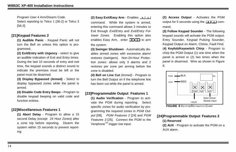
[23]Programmable Output Features 1(1) Audio Verification - Program to acti-vate the PGM during reporting. Selectspecific zones for audio verification by pro-gramming the required zones in PGM Out-put [08], PGM Features 2 [24] and PGMFeatures 3 [25]. Connect the PGM to theVeriphoneTM trigger low input.
(2) Access Output - Activates the PGMoutput for 5 seconds using the com-
mand.(3) Follow Keypad Sounder - The followingkeypad sounds will activate the PGM output:Entry Sounder, Keypad Pulsing Sounder,Keypad Output on Alarm, Chime, Fault Find.(4) Keyfob/Keyswitch Chirp - Program tochirp the PGM Output (1) one time when thepanel is armed or (2) two times when thepanel is disarmed. Wire as shown in Figure6.
[24]Programmable Output Features 2(1) Reserved(2) AUX - Program to activate the PGM on aAUX alarm.
N/O N/CCOM
BLK
RED
+AUX
Siren DriverSteady Input
PGM
+AUX
K1
FIGURE 6 KEYFOB/KEYSWITCH CHIRP
Wi853c page 14
Tuesday, September 16, 1997 10:42
15
(3) Panic - Program to activate the PGM ona Panic alarm.(4) Test Timer - Program to activate thePGM during a Test Timer report.
[25]Programmable Output Features 3(1) AC Fail - Program to activate the PGM onthe loss of AC. (15 minute delay)(2) Low Battery - Program to activate thePGM on a Low Battery condition.(3) *Trouble - Program to activate the PGMon a Trouble condition.(4) Armed - Program to activate the PGMwhen the panel is Armed. The PGM outputwill flash when the panel has gone intoalarm.
*Includes Bell Cut, Receiver Fail-to-Respond, Receiver Tamper and ReceiverJAM.
[26]Miscellaneous Features 2(1) Momentary Keyswitch Arming - Typi-cally, connect a normally-open Keyswitchacross the zone AND its 3.3K zone-doublingresistor.
(2) Reserved .(3) Inhibit Fail-to-Communicate Display -This option prevents the keypad from eitherindicating or sounding when a Fail to Com-municate has occurred.(4) Inhibit Low Battery Display - Programto inhibit the Low Battery Display at thekeypad. Low Battery Reporting is not inhib-ited. The programming option is not per-mitted for UL installations.
7HOHSKRQH 1XPEHU 3URJUDPPLQJ
[30]Subscriber ID NumberFor 4/2 format enter a 4 digit number. If 3/1format is required, enter a 3 digit number,then press the ) key to blank the last
digit.
[31]Telephone Number 1Program the phone number to be dialed forTelephone Number 1. Program the num-ber directly, just as it is entered on a Touch-Tone phone. A fixed Dial Tone Detection(E) is included prior to the Dialing Prefix(Block Number 44). Programming an E is
not required for Telco 1, Telco 2 and Telco 3.If dial tone detection is not desired select NoDial Tone Detection in Communicator Fea-tures [46-1].s Use the ) key to blank out
remaining digits in the phone number.
[32]Receiver FormatSelect the receiver format to be used toreport for Telephone Number 1: Program a0 to disable reporting to Telco 1.
[0] Disabled [4] Universal High Speed[1] Ademco Slow [5] Reserved[2] Radionics Slow [6] Point ID[3] Silent Knight Fast [7] Pager
3DJHU 3URJUDPPLQJ
If Pager Format ([32]and/or[42]and/or[52] =7) is selected, pager data will be displayedas shown in Figure 7. If Pager Format isselected 4/2 format must be programmedand Sumcheck is not permitted. If a PINnumber is required refer to Pager Extend[33-4].
Wi853c page 15
Tuesday, September 16, 1997 10:42

16
WI853C XP-400 Installation Instructions
Pager Alarm data is the same as 4/2 formatwith the exception that the 2 digit ReportCode is transmitted before the 4 digit Sub-scriber ID.
[33]Receiver Options(1) 2300 Hz HS/Kissoff - Select 2300 HzHandshake and Kissoff.(2) Sumcheck - Only used for the followingReceiver Formats: Ademco Slow, RadionicsFast, Silent Knight Fast and Universal HighSpeed. This is a sophisticated data formatused to enhance the speed and check theaccuracy of the received transmission. Thisformat should be used whenever the centralstation has this capability. Instead of send-ing a second round to verify correct data, thepanel sends a Sumcheck digit after sendingthe Subscriber ID and Alarm Code.
(3) Single Digit - 3/1 Format. 3-digit Sub-scriber ID number and a 1-digit Alarm Codewill be transmitted.
(4) No Handshake/Pager Extend - Themeaning of this option is dependent onReceiver Format programming.No Handshake (All receiver formats except
Pager Format)
If programmed no Handshake is re-quired.Pager Extend (Pager Format Selected)
Pager PIN Number - Program if a PINnumber is required by the paging sys-tem. The digits in Telephone Number2 will be added on to telephone num-ber 1 and/or telephone number 3 al-lowing for a total of 24 digits. Seesample program below. Note: If se-lected do not program backup report-ing.If a 7-digit PIN number is required,program the panel as follows:
[31] - Pager Telephone number[32] - Select Pager Format
[33] - Select Pager Extend
[41] - D D D X X X X X X X C 0
[34]Zone Report, Telco 1Select zone(s) required to send an alarmreport to Telephone Number 1.
[35]Zone Restore Report, Telco 1Select zone(s) required to send a restorereport to Telephone Number 1. The zoneswill send a restore after Bell time-out, unlessprogrammed as silent zones.
[36]System Reporting, Telco 1(1) Keypad Panic 2 - Program to activate aKeypad Panic 2 report ().
(2) AUX/AMBUSH - Program to activate anAUX or AMBUSH report (&&).
(3) Panic - Program to activate a Panicreport (').
PIN Number Terminating Digit (#)
Delay Leading 0
Pager display will appear as shown in Figure 7except there will be only one leading 0.
Leading Digits
Report Code
Subscriber ID Number
FIGURE 7 DEFAULT PAGER DISPLAY
Wi853c page 16
Tuesday, September 16, 1997 10:42
17
(4) Test Timer - Program to activate a TestTimer report.
[37]System Reporting, Telco 1(1) AC Fail Report - Program to activate anAC Fail report (15 minute fixed report delay).(2) Low Battery Report - Program to acti-vate a Low Battery report.(3) *Trouble Report - Program to activate aTrouble report.(4) Reserved*Includes Bell Cut, Receiver Fail-to-Respond, Receiver Tamper and ReceiverJAM. Point ID format will report trouble(s) bydevice and ID number.
[38]System Restore Report, Telco 1(1) AC Restore - Program to activate an ACRestore report.(2) Battery Restore - Program to activate aBattery Restore report.(3) Trouble Restore - Program to activate aTrouble Restore report.(4) Reserved
[39]Opening/Closing Report, Telco 1Select users required to send opening andclosing reports to Telephone Number 1.Do not program for users that are intendedto send an Opening After Alarm (CancelCode) or Conditional Closing reports
%DFNXS 7HOHSKRQH 3URJUDPPLQJ
[40]Subscriber ID Number (Telco 2)For 4/2 format enter a 4 digit number. If 3/1format is required enter a 3 digit numberthen press the ) key.
[41]Telephone Number 2Program the phone number to be dialed forTelephone Number 2. A fixed dial tonedetection (E) is included prior to the DialingPrefix [44]. Dial tone detection can bedisabled by programming No Dial ToneDetection [46-1]. To program any addi-tional delay enter a "D" where required inthe phone number.
[42]Receiver Format (Telco 2)Select the format that will be used to reportfor Telco 2 (Backup reporting). Refer tosection [32].
[43]Receiver Options (Telco 2)Refer to section [33] Receiver Options.
[44]Dialing PrefixDialing prefix for Telco 1, Telco 2, and Telco3. Program if using an Outside accessnumber.
[45]Communicator Features 1(1) Communicator Enabled - Program toenable the communicator.(2) DTMF with Rotary Backup - The firstattempt to communicate is dialed using theTouchTone method of dialing, subsequentattempts are dialed using the pulse methodof dialing. Disable this feature to dial usingonly rotary dialing.(3) DTMF only - All attempts to communi-cate dial using the TouchTone method ofdialing.(4) Backup Reporting to Telco 2 - After 2attempts are made to communicate to Telco1 the backup phone number is dialed (Telco2).
Wi853c page 17
Tuesday, September 16, 1997 10:42

18
WI853C XP-400 Installation Instructions
[46]Communicator Features 2(1) No Dial Tone Detection - Program todisable dial tone detection for Telco 1, Telco2 and Telco 3.(2) 2:1 Rotary Dialing - Changes the makebreak ratio when rotary dialing from 1.5:1 to2:1.(3) Backup if < 4 attemps - If BackupReporting [45-4] has been enabled, the com-municator will use Telephone Number 2 [41]for the remaining retries when there are lessthan 4 retries remaining.(4) Reserved
7HOHSKRQH 1XPEHU 3URJUDPPLQJ
[50] - [59]Programming is the same as for Telco 1.Program to split/double report to Telco 3.Refer to sections [30] through [39].
5HSRUW &RGHV
[60]Zone Report CodesReport Code for Zones 1 through 4.4/2 format - The Zone Report Code is the1st digit of the report code sent, the second
digit is the zone number of the reportingzone. For example, if zone 2 has a report-code of 3, the report code would be 32.3/1 format - Sends only the report Codeand does not append it with the zone num-ber.
[61]Point ID Report CodesPoint ID Report Codes are defaulted toBurglary for zones 1 through 4. Optionally,Point ID codes for zones 1 through 4 canbe programmed as follows:
[1] Reserved [7] Gas Alarm[2] Panic [8] Heat Alarm[3] Burglary [9] Reserved[4] Holdup [A] Auxiliary[5] General Alarm [B] 24 Hour[6] Reserved
[62]Zone Codes[62-1] Restore code - Zones 1 through 8.The second digit of the restore code is thezone number of the restored zone. Forexample, if the Zone Restore Code [62] isprogrammed to E, the restore code for thatzone would be E4 (4/2 format).[62-2] Trouble Code - Conditional ClosingReports. Zones that are bypassed at the
time of arming send this code along with thezone number of the bypassed zone(s). Forexample a conditional closing by User 2,with zones 2 and 3 bypassed would be asfollows: 1234 C2
F2F3
[63]System Report CodesProgram a 2-digit report code for KeypadPanic 2, Keypad AUX, Keypad Panic, TestTimer, AC Fail, Low Battery and Trouble.
[64]System Restore CodeThe code sent when a system conditionrestores. The second digit of the 2-digitrestore code is the second digit of the Sys-tem Report Code [63]. For example, if a LowBattery System Report Code is F8 the Bat-tery Restore would be E8 (4/2 format).
[65]Opening and Closing CodesProgram Opening and Closing Codes forUsers 1 through 4. The second digit of thereport code is the number of the user thatarmed or disarmed the system. For exam-ple, if the Closing Code [65] is programmedwith a C, the closing code for User 2 wouldbe C2 (4/2 format).
Wi853c page 18
Tuesday, September 16, 1997 10:42
19
[66]Ambush Report CodeProgram a 2-digit report code for Ambush.To send an ambush report, program a UserCode for User 4, Program report User 4 asAmbush [20-4] and Select reporting for Telco1 [36-2] and/or Telco 3 [56-2].
(QKDQFHG &RPPXQLFDWRU )HDWXUHV
[67]Telephone Number 1(1) Opening After Alarm (Cancel Code) -When enabled, all users that are not se-lected to report on Opening/Closing [39] willreport an Opening only when opening afteran alarm has occurred.(2) Conditional Closing Telephone 1 -When enabled, all users that are not se-lected to report an Opening/Closing ([39],[59]) will report a Closing only when zoneshave been bypassed. The Zone TroubleCode [62-2] is used to report zones that havebeen bypassed at the time of the closingreport.(3) Reserved(4) Reserved
[68]Telephone Number 3(1) Opening after Alarm (Cancel Code) -see [67-1].(2) Conditional Closing Telco 3 - see[67-1].(3) Reserved(4) Reserved
:LUHOHVV
Up to two receivers can be wired to theXP-400. Each wireless transmitter can bemapped to a zone. Only 1 wireless deviceis permitted per zone, however, the use ofboth hardwired and wireless on a zone ispermitted.To Map a transmitter to a zone:
1. Enter the Programming Block Numberthat the transmitter is to be mapped to.
2. Enter the 7-digit RF ID number directly,just as it is shown on the device label.After the 7th digit is entered the keypadwill beep.
A transmitter will send a transmission everytime it is tripped. The transmitter also sendsa supervisory transmission about once everyhour. If the receiver does not receive asignal from a transmitter in the time pro-grammed in Wireless Supervisory Timer, asystem trouble ’RF Supervisory Failure' willbe indicated at the keypad.
Program Wireless Supervisory Timer [16] tochange the supervisory time from the defaultof 12 hours.The Signal strength of a transmitter can bechecked at the keypad (see Fault
Find Mode).
Wi853c page 19
Tuesday, September 16, 1997 10:42
20
WI853C XP-400 Installation Instructions
[71-74] Wireless TransmittersEnter the RF ID# and the point number thatis to be mapped to the zone.
Programming ExampleMap point 1 of a window door transmitter withan RF ID# of 0012B0:0 to Zone 3.
1. Enter Dealer Mode.
2. Enter " (beeps) (beeps)
3. Enter
4. Enter (beeps)
Note: If the RF ID# in step 3 is not enteredcorrectly the keypad will emit a 1 secondtone indicating incorrect entry. Repeat steps2 - 4 above.
[81] - [82] Wireless KeyfobsThe GEM-KF is a hand held wireless trans-mitter capable of Arming and Disarming thecontrol panel and/or activating 2 AuxiliaryFunctions. To activate the auxiliary func-tions, press and hold the or key for
1.5 seconds (see WI752 for more informa-tion).
Enter the RF ID# and AUX 1 and AUX 2options for each Keyfob.
AUX 1 & AUX 2Programming Options:
1 PanicProgram a 1 in the AUX 1 and/or AUX 2option to initiate a panic alarm when the or buttons on the Keyfob are
pressed.Additional programming required:Keypad Panic () [20-3]
Panic Report to Telco 1[36-2] and/or Telco3 [56-3].Audible Panic (Optional) [21-1]
2 AUXProgram a 2 in the AUX 1 and/or AUX 2option to initiate a AUX alarm when the
or buttons on the Keyfob are pressed.
Additional programming required:Keypad AUX () [20-2]
AUX Report to Telco 1[36-2] and/or Telco 3[56-2].
3 Bell ONProgram a 3 in the AUX 1 and/or AUX 2option to turn the Bell ON when the or
buttons on the Keyfob are pressed.
Press the button to turn the Bell OFF.
4 PGMProgram a 4 in the AUX 1 and/or AUX 2option to activate the PGM Output when the or buttons on the Keyfob are
pressed. Press the button to turn the
PGM Output OFF.5 InstantProgram a 5 in the AUX 1 and/or AUX 2option to activate Instant Mode when the or buttons on the Keyfob are
pressed.
6 Access on PGMProgram a 6 in the AUX 1 and/or AUX 2option to activate the PGM Output for 5seconds when the or buttons on the
Keyfob are pressed.Addition programming required:Enable Access Output [23-2]
Wi853c page 20
Tuesday, September 16, 1997 10:42

21
7 Full Set SystemProgram a 7 in the AUX 1 and/or AUX 2option to Fully Set the System when the
and the or buttons on the Keyfob
are pressed, or when the or buttons
are pressed when the system is armed withExit/Entry Follower Zones or Home/Awaywith Delay Zones that have been bypassed.
8 InteriorProgram an 8 in the AUX 1 and/or AUX 2option to Bypass Exit/Entry Follower Zonesor Home/Away with Delay Zones when the or buttons on the Keyfob are
pressed (only if the system is programmedexclusively for Home/Away with DelayZones).
'RZQORDGLQJ
[90]Callback Telephone NumberProgram the phone number of the download-ing computer to be dialed by the panel duringa high security download.
[91]Ring CountProgram the number of rings before thepanel will pickup. Ring Method [92-1](Downloading Features) must also be se-lected.
[92]Downloading Features(1) Ring Method - Enable the ring methodof downloading. The panel will pick-up onthe number of rings programmed in RingCount [91].(2) Answering Machine Override - Usingthe downloading computer, call the panel.When the operator has determined that thepanel has received 1-2 rings, pressing the
X key will cause the downloading com-puter to immediately re-dial the panel. Thepanel will pick-up on the first ring.(3) Function 6 Download - Select to en-able the method of downloading
(pg. 8).(4) Reserved .
[93]Auto Download ID NumberEnter the Number that is used by PCPresetwhen downloading using Site Initiated AutoDownloading ( ).
The requirements for Site Initiated AutoDownloading are as follows:1. Download Computer running PCPreset.2. Program the telephone number of the
Download Computer in location [90] Call-back Telephone Number.
3. Program location [93] with the number ofthe PCPreset account that is to be down-loaded.
PCPreset1. Create the XP-400 account to be down-
loaded using PCD3000 QuickloaderSoftware.
2. Create a List using PCPreset.
3. Select the account by pressing WW.Select the desired account from the listof PCD3000 accounts available. (Thelocation in the list is the Auto DownloadID Number [93])
4. Tag the list by entering D' (download)
5. Enter Standby Mode by entering R.
The Computer is now in STANDBY
Wi853c page 21
Tuesday, September 16, 1997 10:42
22
WI853C XP-400 Installation Instructions
SiteAt the site perform the following three steps:1. Arm the panel.2. Disarm the panel.3. Enter . The panel will now call
the download computer running PCPre-set. PCPreset will answer the call, es-tablish a connection, and then downloadthe account that matches the AutoDownload ID Number [93] with the ac-count of the same number in the list thatPCPreset is currently running.
'HDOHU 3URJUDPPLQJ
[94]Dealer CodeThe default Dealer Code is 4567. Programa new 4-digit Dealer Code. When the panelis defaulted the Dealer Code will be changed
back to the default Dealer Code of 4567only if Dealer Code Lockout [96-1] has not been programmed.
[95]User 1 CodeThe 1st User code is a program code aswell as an Arm/Disarm code. The default
User Code is 1234. If User 1 Code Lock-out is programmed the User 1 Code cannotbe programmed from User Program Mode.
[96]Dealer Options 1(1) Dealer Code Lockout - Program toprevent the Dealer Code from changingwith a panel default.(2) User 1 Code Lockout - If programmedthe User 1 Code cannot be programmedfrom User Program Mode.(3) Reserved(4) Reserved
[97]Dealer Options 2
(1) International Dialing Protocol - Nodialing if no dial tone, 60 seconds betweenattempts and 4 s wait for dial tone.(2) Invert Bell Output - Inverts the Bellpolarity and removes supervision from thebell circuit.
(3) System Trouble Auto Restore - Nor-mally, System troubles require acknowledg-ment (View System Trouble) in order to re-store. If this option is selected troubles willrestore without requiring acknowledgment.(4) User 1 Code-Program only - If enabledUser 1 Code will function only as the UserProgram Code and will not Arm/Disarm thepanel.
Note: All programming within ProgrammingBlocks [96] & [97] will not change if the panelis defaulted.
[98] Number of Re-DialsThe Number of re-dial attempts made by thepanel before indicating a Fail-to-Communicate.
Wi853c page 22
Tuesday, September 16, 1997 10:42

23
6\VWHP 7URXEOHV
Use the System Trouble chart on the followingpage to determine the specific System Trou-ble(s).
During normal panel operation theSYSTEMLED has the following two modes of operation:
STEADY 1-7 possible trouble groups, AC is present
FLASHING 1-7 possible trouble groups, AC is not present
9LHZLQJ 6\VWHP 7URXEOHV
Press the key on the keypad. To determinethe System Trouble Group Number, count thenumber of times theSYSTEM LED blinks.The keypad sounder will beep at the same ratethat theSYSTEM LED blinks.
To determine the System Trouble, note the zoneLED that is ON. Look up the specific systemtrouble on the chart on the following page.
TheSYSTEM LED and keypad sounder willcontinue to flash and beep. To view the nextSystem Trouble, if any, press the key. Con-tinue pressing the key, if there are no moresystem troubles to view, the system will return tonormal operation.
Note: System Troubles Groups 3 through 7 -System Trouble Groups that have a zone asso-ciated with the trouble, such as RF low battery.The zone(s) of the device with a low battery willbe displayed by the ZONE LED . For example,a wireless low battery on zone 2 would beep thekeypad sounder 3 times and turn on zone 2LED.
Audible System Trouble Indication - For allsystem troubles, except when the only systemtrouble is the loss of AC, the keypad will beeponce every 10 seconds. The keypad will continueto beep until the reset button is pressed or thetrouble has been acknowledged by pressing the) key.
System Trouble ReportingThe following system troubles, when enabled toreport to Telco 1 [37-3] or Telco 3 [57-3], will sendthe report code programmed in Trouble Report[63] if reporting using a pulse format:
System Trouble Pulse Report CodeBell Cut F1Rcvr Fail-to-Respond F1Receiver Tamper F1Receiver JAM F1Tx Low Battery F1Tx Supervisory Failure F1
If reporting using Point ID, a unique code will besent for each of the following System Troubles.System Trouble Point ID Report CodesBell Cut CODE 1 321 G00 ZN000-BELL 1 TROUBLERcvr Fail-to-Respond CODE 1 382 G00 ZN000-SENSOR TROUBLEReceiver Tamper CODE 1 145 G00 ZN000-EXP. MODL. TAMPERReceiver JAM CODE 1 373 G00 ZN000-FIRE LOOP TRBLETx Low Battery CODE 1 384 G00 ZN00n-RF TRAN LOW BATTTx Supervisory Failure CODE 1 381 G00 ZN00n-SUPERVSN LOSS RF
A 300 (SYSTEM TROUBLE RST) code is sent if a restore isreported after multiple troubles.
System TroubleGroup #
Keypad SYSTEM Trou-ble LED is flashing 1time indicating SystemTrouble Group 1.
Keypad Sounder beeps1 time indicating SystemTrouble Group 1.
EXAMPLE - LOW BATTERY SYSTEM TROUBLE DISPLAY
Zone LED(s) is ONindicates(Specific Trouble)
Specific Trouble
Zone 2 LED is ON indicatingLow Battery. (1 Beep, LED 2)
Flashing(SystemTroubleGroupNumber)
Press the ) to enter System Trouble mode and
determine the specific trouble. Press any key to viewall system troubles.
Beeping(SystemTroubleGroupNumber)
FIGURE 8 SYSTEM TROUBLE EXAMPLE
$50(
5($'<
6<67(0**
),5(
$&
=21(
=21(
=21(
=21(
=21( =21(
1$3&2
Wi853c page 23
Tuesday, September 16, 1997 10:42

24
WI853C XP-400 Installation Instructions
Keypad Beeps orSYSTEM
Flashes
Zone LEDON
System TroubleCondition
Cause/Action
1 Beep 1 AC Power Failure This trouble will occur if AC power is not present. Ensure that the transformer is connected to an unswitched power source.
2 Low Battery If there has been a recent power failure, the battery may be partially depleted and must be recharged by the control panel. Ifthe trouble does not go away in 24 hours, replace the battery.
3 CommunicationFailure/PCPreset Fail
The system was not able to report to central station. Check panel programming and telephone line wiring. The trouble willclear after it has been acknowledged by viewing the system trouble as long as the telephone line has passed a line cut test(tested automatically by the panel). The Panel did not sucsessfully connect and download/upload with the commputerrunning PCPreset - check Auto Download ID number, Callback Number or PCPreset Setup.
4 Telephone Line Cut The telephone line has failed. If telephone service has been temporarily interrupted, the trouble will clear when restored andacknowledged by viewing the system trouble.
2 Beeps 1 Bell/Siren line Cut There is a problem with the Bell or Siren wiring. EOL2.2K resistor must be installed.
3 Rcvr Fail-to-Respond/RcvrTamper
The receiver is not responding to the panel. The red LED on the receiver should be flashing, refer to WI848. The cover is offthe receiver causing a tamper signal to be transmitted.
4 Receiver Jam A signal is blocking the normal reception of transmissions from the wireless devices. Ensure that the green LED on thereceiver is not on continuously, refer to receiver manual WI848.
3 Beeps 1-4 WirelessTransmitter Low Battery
The battery in the wireless transmitter is low and should be replaced. This transmitter is on the zone corresponding to thenumber of the zone light flashing. The replacement battery for the GEM Trans2 door/window transmitter and the GEM PIRwireless motion detector is the Duracell DL123A. (2 required for the GEM-PIR) WARNING: Replace batteries only with thesame type as specified above. Use of another battery may present a risk of fire or explosion. Do not recharge or disassemblebattery or dispose of in fire.
4 Beeps 1-4 WirelessTransmitterSupervisory Failure
The panel has not received a supervisory signal from the transmitter within the time programmed. Check WirelessSupervisory Timer [16] Programming. Check the placement of the transmitter and receiver, refer to WI848.
7 Beeps 1-4 Zone Trouble The panel has one or more of the following 3 possible troubles: Zone Short, Transmitter Tamper or Dual Tech Self Test Fail.
6\VWHP 7URXEOHV
Wi853c page 24
Tuesday, September 16, 1997 10:42

25
7URXEOHVKRRWLQJ
1. The bell output drops to about 3 volts inalarm.The battery/bell circuit is protected by a PCboard trace which may have burned openby reversal of the battery leads. It is on theback of the PC board just adjacent to thered & black battery leads. Send in for ser-vice if this occurs.
2. How do I remove the Keypad Sounderon Alarm?The keypad sounder follows the Burg Out-put. If you need to remove the KeypadSounder, then you must remove the BurgOutput from that zone.
3. How do I activate Chime by Zone?The Chime feature will automatically beassigned to all zones, except for the follow-ing:
1. Zones programmed as Home/Awaywith Delay.
Zones programmed as Exit/EntryFollowers
2. Zones programmed for 24 Hour Pro-tection. To Activate/Deactivate the
chime mode, Press .
4. When using a piezo on the Bell Output,it constantly buzzes.This is due to the fact that there is aconstant loop current flowing through theBell circuit for supervision. To eliminate
this, cut resistor R26 which is locateddirectly above Terminal 9 just below theheat sink.
5. Where are the fuses?The control panel incorporates advancedcircuitry which automatically limits the cur-rent when an over current condition existswithout the use of traditional fuses. Thecircuit will restore automatically when theover current condition is corrected.
6. The PGM Output Pulses in Alarm.When the PGM lug of the control panel isprogrammed for an Armed indication it alsoincorporates an Alarm Memory functionwhich will indicate that the system is in anAlarm condition. If this output is being usedto trigger a long range radio, it can beconverted to a steady output with the use of
a capacitor, negative to PGM Terminal 15 ,
Pos to Aux. Pwr. Term 12. (220 mF Elec-trolytic Capacitor, 25 Volts. Increase to 470mF if necessary)
7. I short out the bell and the system doesnot indicate Bell Trouble.The Bell Supervision circuit is only de-signed to detect a "Bell Cut", it does notsupervise for a short on the Bell.
Wi853c page 25
Tuesday, September 16, 1997 10:42

26
WI853C XP-400 Installation Instructions
8. How do I remove Keypad Sounder onAlarm?The keypad sounder follows the Burg Out-put. If you need to remove the KeypadSounder, then you must remove the BurgOutput from that zone.
9. Transmitters not respondin g?Open Transmitter case - Keypad should gointo X-Mitter Tamper Trouble. If not:
Check Receiver Red LED should beflashing once approx. once a second.Check Receiver wiring.Check Programming of Transmitter ID.
If Keypad does go into X-Mitter TamperTrouble, check:
Transmitter point is programmed cor-rectly.Transmitter is wired correctly:If using external switch, make sure it iswired to point 1, and point 2 is jumpedout.
If using internal reed, make sure J1 iscut and both Point 1 and Point 2 termi-nals are jumped out.
10. Keypad LEDs Flicker.The Keypad is not receiving a POLL fromthe Panel.Check Keypad wiring.
1. The Panel is in the process of beingUploaded/Downloaded.
2. The panel is powering up. LED’swill flicker until panel has reset andis polling the keypad.
3. The connection from the controlpanel to the keypad is open.
11. No Keypad Entry Sounder durin g En-try Time?The keypad sounder is turned off with the
command. This command will
silence all Keypad sounds except keypad
sounder on alarm. Enter to turn
keypad sounds back on.
12. No Keypad Chime?The keypad sounder is turned off with the
command. This command will si-
lence all Keypad sounds except keypad
sounder on alarm. Enter to turn
keypad sounds back on.
Wi853c page 26
Tuesday, September 16, 1997 10:42

27
16 VAC 20 VATRANSFORMERNAPCO TRF12(OR EQUIVALENTSEE WI879A).Class 2Transformer.DO NOTconnect toswitchedoutlet.
-4 +5 +6 1 2 +3
GEM-RECV-XP8
RED
BLACK
E1
E2
RECHARGEABLEBATTERY
12 VDC 4AH OR 7AH
ALL OUTPUTS ARE CURRENT LIMITED
WARNINGTO PREVENT RISK
OF ELECTRIC SHOCKDISCONNECT TELEPHONE
LINES PRIOR TO SERVICING
EARTHGROUND
BELL
Program
mable
Output
PGM(-)
12
+PWR
+10 -11 +12 -13 14 15 16 17 18 19 -7 +8 -9 GND +PWR GND GREEN TIP RING TIP RING
PHONE
(Supervised)To RJ31X
2.2K EOLR(SUPERVISED)
+
+
GOLDRED RED
RED
COLD WATER GROUNDCONNECTIONUSE ONLY COLD-WATERPIPE OR BURIED GROUNDROD. USE AT LEAST #16AWG WIRE.
TELCO
RE
D
GR
N
GR
AY
BR
N
/2
A'
P$0$;
REMOTE BUS
(E)
.
ZONE 4
(Z)
ZONE 1
(E)
.
ZONE 3
2.2K
(E)
5('
%/.
*51
(E)
(Z)
*2/'
:+,7( 5('
3.9K
25$1*(
.
EZZoneDoublingTM
ResistorsA
UX
PO
WE
R O
UT
PU
T 10-12.5 V
DC
(1) ALL ZONE RESISTORS MUST BE INSTALLED,EVEN IF ZONE IS NOT USED.
(2) COMBINED STANDBY = KEYPAD CURRENT +AUX POWER CURRENT + PGM CURRENT.
XP-400 WIRING DIAGRAM (REFER TO INSTALLATION INSTRUCTIONS WI853C)
RESIDENTIAL BURG (4 HOUR STANDBY) (2)
COMBINED STANDBY = 350 mA BELL = 2.0 AMP
(1)
(Z)
NOT USED
Normally Open Zone Wiring
Wire the normallyopen contactas shown (Zone 4).Program thezone forOpen Circuit [06]operation.
(Z)
ZONE 1
(E)
.
ZONE 4
.
.
. RPX-4
ZONE 2
Wi853c page 27
Tuesday, September 16, 1997 10:42

28
WI853C XP-400 Installation InstructionsNAPCO LIMITED WARRANTYNAPCO SECURITY SYSTEMS, INC. (NAPCO) warrants its products to be free from manufacturing defects in materials and workmanship for thirty-six months following the date of manufacture.NAPCO will, within said period, at its option, repair or replace any product failing to operate correctly without charge to the original purchaser or user.This warranty shall not apply to any equipment, or any part thereof, which has been repaired by others, improperly installed, improperly used, abused, altered, damaged, subjected to acts of God, oron which any serial numbers have been altered, defaced or removed. Seller will not be responsible for any dismantling or reinstallation charges.THERE ARE NO WARRANTIES, EXPRESS OR IMPLIED, WHICH EXTEND BEYOND THE DESCRIPTION ON THE FACE HEREOF. THERE IS NO EXPRESS OR IMPLIED WARRANTY OFMERCHANTABILITY OR A WARRANTY OF FITNESS FOR A PARTICULAR PURPOSE. ADDITIONALLY, THIS WARRANTY IS IN LIEU OF ALL OTHER OBLIGATIONS OR LIABILITIES ON THEPART OF NAPCO.Any action for breach of warranty, including but not limited to any implied warranty of merchantability, must be brought within the six months following the end of the warranty period. IN NO CASESHALL NAPCO BE LIABLE TO ANYONE FOR ANY CONSEQUENTIAL OR INCIDENTAL DAMAGES FOR BREACH OF THIS OR ANY OTHER WARRANTY, EXPRESS OR IMPLIED, EVEN IFTHE LOSS OR DAMAGE IS CAUSED BY THE SELLER'S OWN NEGLIGENCE OR FAULT.In case of defect, contact the security professional who installed and maintains your security system. In order to exercise the warranty, the product must be returned by the security professional,shipping costs prepaid and insured to NAPCO. After repair or replacement, NAPCO assumes the cost of returning products under warranty. NAPCO shall have no obligation under this warranty, orotherwise, if the product has been repaired by others, improperly installed, improperly used, abused, altered, damaged, subjected to accident, nuisance, flood, fire or acts of God, or on which anyserial numbers have been altered, defaced or removed. NAPCO will not be responsible for any dismantling, reassembly or reinstallation charges. This warranty contains the entire warranty. It is thesole warranty and any prior agreements or representations, whether oral or written, are either merged herein or are expressly canceled. NAPCO neither assumes, nor authorizes any other personpurporting to act on its behalf to modify, to change, or to assume for it, any other warranty or liability concerning its products. In no event shall NAPCO be liable for an amount in excess of NAPCO'soriginal selling price of the product, for any loss or damage, whether direct, indirect, incidental, consequential, or otherwise arising out of any failure of the product. Seller's warranty, as hereinaboveset forth, shall not be enlarged, diminished or affected by and no obligation or liability shall arise or grow out of Seller's rendering of technical advice or service in connection with Buyer's order of thegoods furnished hereunder.NAPCO RECOMMENDS THAT THE ENTIRE SYSTEM BE COMPLETELY TESTED WEEKLY.Warning: Despite frequent testing, and due to, but not limited to, any or all of the following; criminal tampering, electrical or communications disruption, it is possible for the system to fail to performas expected. NAPCO does not represent that the product/system may not be compromised or circumvented; or that the product or system will prevent any personal injury or property loss by burglary,robbery, fire or otherwise; nor that the product or system will in all cases provide adequate warning or protection. A properly installed and maintained alarm may only reduce risk of burglary, robbery,fire or otherwise but it is not insurance or a guarantee that these events will not occur. CONSEQUENTLY, SELLER SHALL HAVE NO LIABILITY FOR ANY PERSONAL INJURY, PROPERTYDAMAGE, OR OTHER LOSS BASED ON A CLAIM THE PRODUCT FAILED TO GIVE WARNING. Therefore, the installer should in turn advise the consumer to take any and all precautions for hisor her safety including, but not limited to, fleeing the premises and calling police or fire department, in order to mitigate the possibilities of harm and/or damage. NAPCO is not an insurer of either theproperty or safety of the user's family or employees, and limits its liability for any loss or damage including incidental or consequential damages to NAPCO's original selling price of the productregardless of the cause of such loss or damage.Some states do not allow limitations on how long an implied warranty lasts or do not allow the exclusion or limitation of incidental or consequential damages, or differentiate in their treatment oflimitations of liability for ordinary or gross negligence, so the above limitations or exclusions may not apply to you. This Warranty gives you specific legal rights and you may also have other rightswhich vary from state to state.
THE FOLLOWING STATEMENT IS REQUIRED BY THE FCC.This equipment generates and uses radio-frequency energy and, if not installed and used properly, that is, in strict accordance with the manufacturer's instructions, may cause interference to radioand television reception. It has been type tested and found to comply with the limits for a Class-B computing device in accordance with the specifications in Subpart J of Part 15 of FCC Rules, whichare designed to provide reasonable protection against such interference in a residential installation.However, there is no guarantee that interference will not occur in a particular installation. If this equipment does cause interference to radio or television reception, which can be determined by turningthe equipment off and on, the user is encouraged to try to correct the interference by one or more of the following measures: reorient the receiving antenna; relocate the computer with respect to thereceiver; move the computer away from the receiver; plug the computer into a different outlet so that computer and receiver are on different branch circuits.If necessary, the user should consult the dealer or an experienced radio/television technician for additional suggestions. The user may find the following booklet prepared by the FederalCommunications Commission helpful: <169>How to Identify and Resolve Radio-TV Interference Problems.<170> This booklet is available from the U.S. Government Printing Office, Washington, DC20402; Stock No. 004-000-00345-4.
Wi853c page 28
Tuesday, September 16, 1997 10:42