Embed Size (px)
Citation preview

XonTel XT-1600G/XT-2400G PoE Switches
Web Management User-Guide
Contents Chapter 1、WEB page overview ............................................................................................................ 1
1、WEB Access features ................................................................................................................ 1
2、WEB browsing system requirements ........................................................................................ 1
3、WEB browsing session landing ................................................................................................ 2
4、WEB page elements .................................................................................................................. 2
5、The structure of Navigation tree ............................................................................................... 3
6、Page button Introduction ........................................................................................................... 3
7、Error messages .......................................................................................................................... 4
8、Entry Field ................................................................................................................................ 4
9、Status Field ............................................................................................................................... 4
Chapter 2、WEB page introduction ....................................................................................................... 5
1、Login dialog Box ...................................................................................................................... 5
2、Main Page ................................................................................................................................. 6
3、System Configuration: .............................................................................................................. 6
4、Port Configuration .................................................................................................................. 11
5、MAC binding .......................................................................................................................... 16
6、MAC filtering ......................................................................................................................... 17
7、VLAN Configuration .............................................................................................................. 18
8、SNMP Configuration .............................................................................................................. 19
9、ACL Configuraion .................................................................................................................. 20
10、QoS Configuration ................................................................................................................ 23
11、IP Basic Configuration .......................................................................................................... 24
12、Certification. Authorization. Accounting (AAA) configuration ........................................... 26
13、PoE port configuration .......................................................................................................... 28

WEB page operating manual This manual focus on describing the WEB page of XonTel XT-1600G/XT-2400G switches,
the user can managed the XonTel XT-1600G/XT-2400G switches through WEB page. This manual only introduce the simple operations of the various WEB page of the various switches. This manual includes the following: 1, WEB page overview 2, WEB page description
Chapter 1、WEB page overview
1、WEB Access features
XonTel XT-1600G/XT-2400G switches provide users with Web access functionality. Via Web browser, users can access switches, manage and configure the switch. WEB accessing‘s main features are: 1, Easy to access: Users can easily access on switch from anywhere using the network.
2, users can visit the WEB pages of the switch by using the familiar Netscape Communicator and Microsoft Internet Explorer and other browsers, WEB pages of graphical and tabular format presented to the user.
3, Switch switch provides a wealth of WEB pages, the user can configure and manage vast majority of functions of the switch. 4, WEB page’ function classification &integration, make the user find the relevant pages to configuration and management.
2、WEB browsing system requirements
Please see the form 1。
Form 1:
Hardware&Software system requirements
CPU Pentium 586 above
Memory 128MB above
Resolution 800x600 above
Color 256 colors above
Browser IE4.0 above or Netscape4.01 above
Operating system Microsoft® ,Windows95®,Windows98®,WindowsNT®, Windows2000®, WindowsXP®,WindowsME®, WindowsVista®, Linux,Unix ect.
Note:
Microsoft ®, Windows95 ®, Windows98 ®, WindowsNT ®, Windows2000 ®, WindowsXP ®,
Windows ME ®, WindowsVista ® is a registered trademark of Microsoft Corp. All other product
names, trademarks, registered trademarks and service marks, copyrights held by their respective
owners.

3、WEB browsing session landing
Before start Web browsing session ,the user need to make sure:
1. Has configure the IP of switch, under the default case, the switch VLAN1 interface IP address is 192.168.0.1, 2. subnet mask is 255.255.255.0.
3. Has a Web browser installed on the host to connect to the network, and the host can PING-pass switches. 4. After completing these two tasks, the user put the right address on the browser's address bar of the switch and press Enter to enter the switch after the Web login page, shown in Figure 1. When the multi-user management is not enabled, the user login need for anonymous Web user (admin) password for authentication, and only entered the correct password can access Web, anonymous user password by default is (xontel).
If the system enabled a multi-user management and configure the privileged user, the
anonymous user's password will not force users to visit the Web.user access not do anonymous user's password authentication, but to do a multi-user management, user name and password authentication.
Figure 1
4、WEB page elements
Shown in Figure 2, WEB page is mainly composed of three parts: title page, navigation tree page and main page

Figure 2
Title page is Used to display the logo main page Is used to display the user from the navigation tree, select the page
5、The structure of Navigation tree
Figure 3 shows the navigation tree organizational structure. Navigation tree is located in the lower left of each page, using the tree display nodes of the
WEB page, users can easily find the page you want to manage the WEB. According to a different web page functionality can be divided into different groups, each including one or more pages. Most of the navigation tree in the name of the corresponding web page top of page title abbreviation.
Figure 3
6、Page button Introduction
On the pages, here are Some commonly used button, the role of these buttons are generally the same, Form 2 on the role of these buttons are described:
Form 2:
button effect
Refresh Update all fields on the page
Apply numerical value will be updated into the memory. Because the error-checking should be implement by the Web Server, before the user selects the button will be no error checking.

Delete Delete the current record
Help Open help pages, view the individual pages of the configuration instructions
7、Error messages
If the switch WEB server error occurred while processing user requests, it will display a dialog box in the corresponding error message. For example, Figure 4 shows an error message dialog box.
Figure 4
8、Entry Field
Some pages of the most left column in the table has an entry field, as shown in Figure 5, through the field can access different rows in the table. When you choose a lines for the filed, which lines the corresponding information is displayed in the first line, then only the line can be edited, the line also known as the activities line. A time when it was first loaded, it shows the filed new, activity line is empty.
If want to add a new line , should select new from the drop-down menu of entry field, , enter the new line’s information, and then press apply button.
If you want to edit the line already exists, it is necessary select the appropriate line number of the drop-down menu, according to need to edit the line, and then press the apply button, you will see a corresponding change in the table displayed.
If you want to delete a row, select the line number accordly from entry field’s drop-down menu, then press the delete key, this line will disappear from the table.
Figure 5
9、Status Field
Some pages of the most right column in the table there is a state field, as shown in Figure 6, the field displays the line status. Since all row state changes are processed in-house, so the status field is read-only. Once the line information of the entry filed into force, the line will
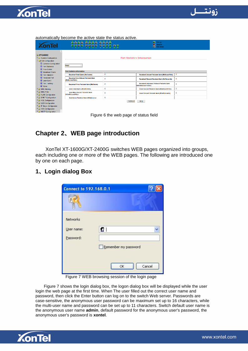
automatically become the active state the status active.
Figure 6 the web page of status field
Chapter 2、WEB page introduction
XonTel XT-1600G/XT-2400G switches WEB pages organized into groups, each including one or more of the WEB pages. The following are introduced one by one on each page.
1、Login dialog Box
Figure 7 WEB browsing session of the login page
Figure 7 shows the login dialog box, the logon dialog box will be displayed while the user
login the web page at the first time. When The user filled out the correct user name and password, then click the Enter button can log on to the switch Web server. Passwords are case-sensitive, the anonymous user password can be maximum set up to 16 characters, while the multi-user name and password can be set up to 11 characters. Switch default user name is the anonymous user name admin, default password for the anonymous user's password, the anonymous user's password is xontel.
2、Main Page
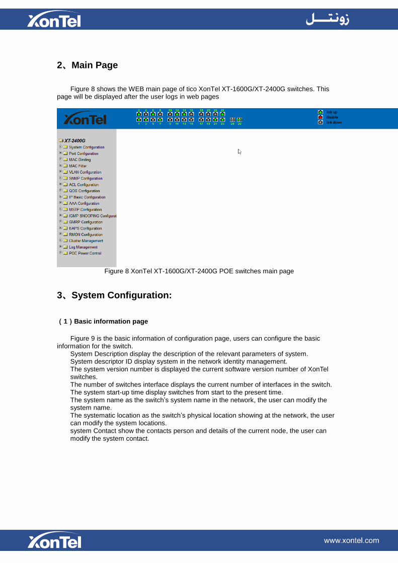
Figure 8 shows the WEB main page of tico XonTel XT-1600G/XT-2400G switches. This page will be displayed after the user logs in web pages
Figure 8 XonTel XT-1600G/XT-2400G POE switches main page
3、System Configuration:
(1)Basic information page
Figure 9 is the basic information of configuration page, users can configure the basic
information for the switch. System Description display the description of the relevant parameters of system. System descriptor ID display system in the network identity management. The system version number is displayed the current software version number of XonTel switches. The number of switches interface displays the current number of interfaces in the switch. The system start-up time display switches from start to the present time. The system name as the switch’s system name in the network, the user can modify the system name. The systematic location as the switch’s physical location showing at the network, the user can modify the system locations. system Contact show the contacts person and details of the current node, the user can modify the system contact.

Figure9 Basic information Page
(2)Serial port information page
Figure 10 is a serial port configuration page, the page displays serial baud rate and other related information. When the host through the serial port terminals (such as Windows, HyperTerminal) to the management of switches, serial console on the COM port configuration must be consistent with this page information.
Figure 10 Serial port information page
(3)User management page
Figure 11 is a user management page, the user can modify this switch anonymous user (admin) password, Telnet and the Web without opening a multi-user, they all use the same anonymous user's password. Passwords are case-sensitive, and can be up to 16 characters. If you want to change your password, the user need to enter the new password twice, once the user clicks the application button, the new password is activated, then if the switch is not enabled multi-user, will display the login dialog box (as shown in Figure 7), require the user to re - login the web page, with a new anonymous user password.
Meanwhile through this page user can configure the multi-user, switch if in the default is no multi-users that is, not enabled the multi-user management functionality, at this time does not require multi-user login user name and password authentication. For Telnet, when adding a

user name, multi-user management features were enabled, and when removed all of the user, multi-user management functionality has been closed. For the Web, when adding a user name, if it is privileged user, multi-user management functionality was enabled, when all of the privileges users have been deleted, multi-user management functionality has been closed. When the multi-user management features enabled, the anonymous user's password will not take effect, log Telnet and the Web requires a multi-user user name and password authentication. When the multi-user management function is turned off, at this time if the configured anonymous user's password, log on Telnet, and Web need anonymous user's password authentication
Figure 11 user’s management page
(4)Security Management Page
Figure 12 is Security management configuration page, through the page's configuration, ,
the administrator can control network management services TELNET, WEB and SNMP, you can open (enable) or off (disable) these services, these services can be mounted up with standards IP ACL group ,and the implementation of the source IP address control, control access to the host of these services
When the Switch default ,TELNET, WEB and SNMP services are open and no ACL filtering, that is, all hosts have access to the switch of these three services. If the administrator for safety, do not want to provide one or several services, which can shut down one or several services. If the administrator only hope that the specified host could access one or several services , can do the ACL filtering for one or several services. As a service to do ACL filtering, you need to open the service, and to select an IP standard ACL group (1-99),the primary factor it’s the ACL group must be present.
Note that, if the administrator on this page control the WEB services (such as closing WEB Services) may cause users to no longer use the WEB page, then you can log switches by other means and to control the use of WEB service allows users to WEB page (such as the Open the WEB service).
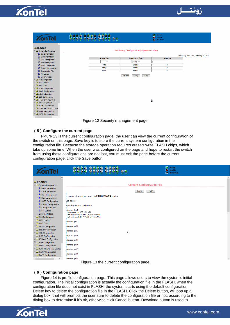
Figure 12 Security management page
(5)Configure the current page
Figure 13 is the current configuration page. the user can view the current configuration of the switch on this page. Save key is to store the current system configuration in the configuration file. Because the storage operation requires erase& write FLASH chips, which take up some time. When the user was configured on the page and hope to restart the switch from using these configurations are not lost, you must exit the page before the current configuration page, click the Save button.
Figure 13 the current configuration page
(6)Configuration page
Figure 14 is profile configuration page. This page allows users to view the system's initial configuration. The initial configuration is actually the configuration file in the FLASH, when the configuration file does not exist in FLASH, the system starts using the default configuration. Delete key to delete the configuration file in the FLASH. Click the Delete button, will pop up a dialog box ,that will prompts the user sure to delete the configuration file or not, according to the dialog box to determine if it's ok, otherwise click Cancel button. Download button is used to

downloaded a configuration file to the PC. Click to download button, will pop up a dialog box, users select Save and save the configuration file directory path. Download the configuration file names are as switch.cfg.
Figure14 Configuration file page
(7)File upload page
Figure 15 is a file upload page, through this page a user can upload a configuration file and
mapping files to the switch. Click the Browse button to select the upload configuration file or image file in the directory path on the PC. Click Upload button upload a configuration file or image file, configuration file extension must be *. cfg, image file must be provided by the manufacturer and the file name extension must be *. img. Transmission before the return of the results page, please do not click on other pages, or restart the switch; otherwise, the file transfer will lead to failure caused by system crashes.
Figure 15 File Upload Page
(8)System reset page
Figure 16 is system reset page, through this page users to restart the switch. When you click on Restart button, will pop up a dialog box that prompts the user to determine whether or restart the switch, If it is determined according to OK button, otherwise click Cancel button. Restart will no longer open the Web page.

Figure16 System reset page
4、Port Configuration
(1)Port configuration / port -display page
Figure 17 is the port configuration / port -display page. Users can enable or disable the port to the page, set the port speed, or View all ports of the basic information.
To set a specific port, users need to select the appropriate port name on port drop-down menu,. The default port status is up, can select the drop-down menu -down to disable the port. Users can also choose to set the speed of the drop-down menu to set the speed of the port, such as the mandatory half-duplex port 10M (half-10) and so on. On this page the user can view all ports other basic information.
Figure 17 port configuration and port - display page
(2)Port Statistics Page
Figure 18 is the port statistics information page. To view a particular port, users need to select the appropriate port name in the port drop-down menu. Users can view the statistics information of send and receive packets on this page.

Figure 18 Port Statistics Page
(3)Flow control page
Figure 19 is the flow control page. Users can enable and disable each port’s send and
receive flow control through this page. Flow control by sending the side of the drop-down on or off to open or close the sending
side of flow control, flow control through the receiving side of the drop-down on or off to open or close the receiver-side flow control, while on and off also shows the port to send side and receiving-side flow control is turned on or off.
Figure 19 Flow control page
(4)Broadcast storm control page
Figure 20 is the Broadcast Storm Control page. This page is used to do the suppression for
configure port broadcast packets, multicast packets and DLF packet. From the Port drop-down bar select to configure ports. Through the on and off key to open and close the port broadcast suppression, multicast, DLF inhibition and suppression. Inhibition rate is used to configure the port inhibition speed, range 1-1024000, unit kbits. The inhibition rate of the same port broadcast suppression, multicast and DLF inhibition is the same.
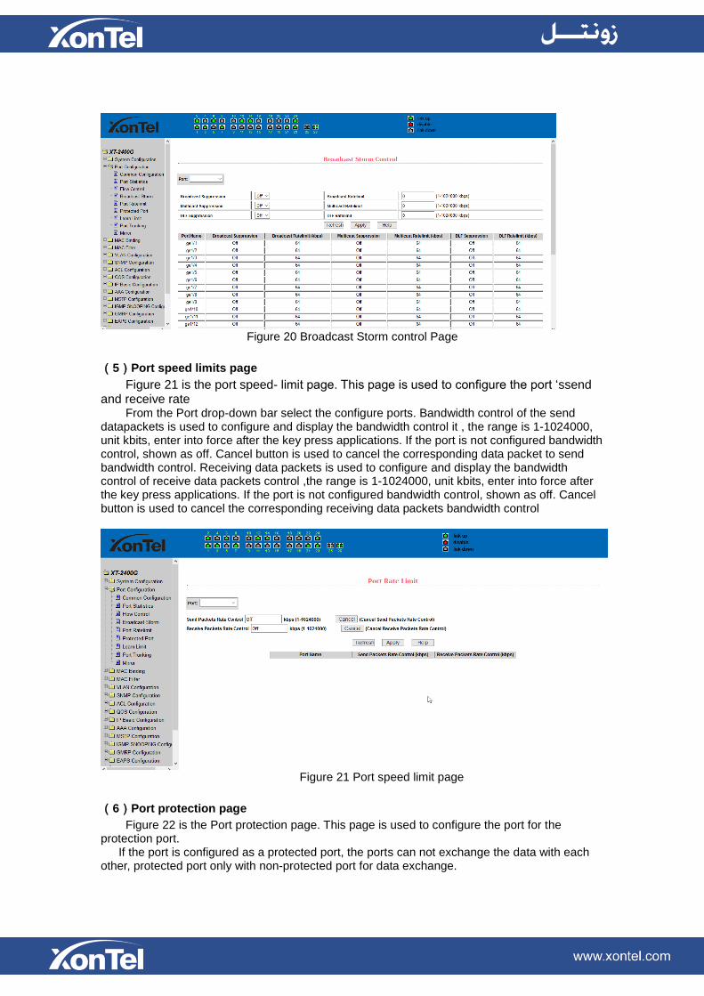
Figure 20 Broadcast Storm control Page
(5)Port speed limits page
Figure 21 is the port speed- limit page. This page is used to configure the port ‘ssend and receive rate
From the Port drop-down bar select the configure ports. Bandwidth control of the send datapackets is used to configure and display the bandwidth control it , the range is 1-1024000, unit kbits, enter into force after the key press applications. If the port is not configured bandwidth control, shown as off. Cancel button is used to cancel the corresponding data packet to send bandwidth control. Receiving data packets is used to configure and display the bandwidth control of receive data packets control ,the range is 1-1024000, unit kbits, enter into force after the key press applications. If the port is not configured bandwidth control, shown as off. Cancel button is used to cancel the corresponding receiving data packets bandwidth control
Figure 21 Port speed limit page
(6)Port protection page
Figure 22 is the Port protection page. This page is used to configure the port for the protection port. If the port is configured as a protected port, the ports can not exchange the data with each other, protected port only with non-protected port for data exchange.

Figure 22 protected port page
(7)Port Learning restrain page
Figure 23 is the port learning restrain page. This page used to restrict the port can learn of the MAC address of the number, range is 0-8191. The default value is 8191, also is the maximum that the port is not configured the learning restrain
Figure 23 Port Learning restrain page
(8)Port Trunking configuration page
Figure 24 is the port trunking configuration page,. This page allows the user to configure the port trunking. This page consists of four parts: port trunking ID selection, port trunking method selection, configurable ports and group members port.
To create or modify the port trunking, the user need to select a port trunking ID, port trunking ID from 1 to 3. The user clicks the list box the appropriate port trunking ID, the port trunking of information displayed in the group port. To create a Trunk group, select the appropriate ID in the port trunking ID, click the button "Trunk ID Settings." To set the port trunking method, select one

port trunking method, click the button "polymerization Settings." To increase the trunking ports, the port can be configured to select the trunking port in the configurable, click on "members of the port =" "key. Aggregation from the existing port to remove a port group member ports in the trunking port selected, click on "non-member port" = "key. To delete the entire TRUNK group, then click the "Delete trunk group" button.
In page configuring process, at least one Trunk has been established then polymerization settings can take effect; configured Trunking method is also applied to all on the Trunk groups; in that already exist on the Trunk can add or remove Port members ; in the absence of the port members situation can deletee a Trunk Group.
Switch provides three kinds of port trunking methods: Based on the source MAC address, based on the purpose MAC address, based on the source and purpose MAC addresses.
Switch switch maximum support 3 groups port trunking, can be configured to a maximum of three Trunk Group, Trunk1 and Trunk2 can not trucking Gigabit ports, and each group can be aggregated up to the same four attributes port. Trunk3 only be aggregated Gigabit ports, and up to 2 Gigabit ports can be aggregated. Port aggregation method is common to all of the Trunk.
Figure 24 Port Trunking configuration page
(9)Port mirroring configuration page
Figure 25 is the port mirroring configuration page .the page allows users to configure port mirroring. Port mirroring through the mirror port to monitor the data packets of being mirrored output port and the data packets of being mirrored input port.. mirroring Port can only choose one, being mirrored output port and being mirrored input port can select multiple. This page consists of four components: monitor port, configurable port, monitoring tdirection and mirror configuration information. When you start to configure a mirror port ,firstly configured mirroring port from monitor ports, mirror ports can only have one, and then select the mirror port from the configurable port, select the monitor direction, and press the application key to entry into force, the results is displayed in the mirrored configuration information.
When choose the RECEIVE in direction of monitor, said monitor data packets received, TRANSMIT, said monitor data packets sent, BOTH that monitor all data sent and received packets, NOT_RECEIVE to cancel monitoring received data packets, NOT_TRANSMIT to cancel monitor send data packets, NEITHER cancels monitor data packets received and sent, that is canceling monitor port.
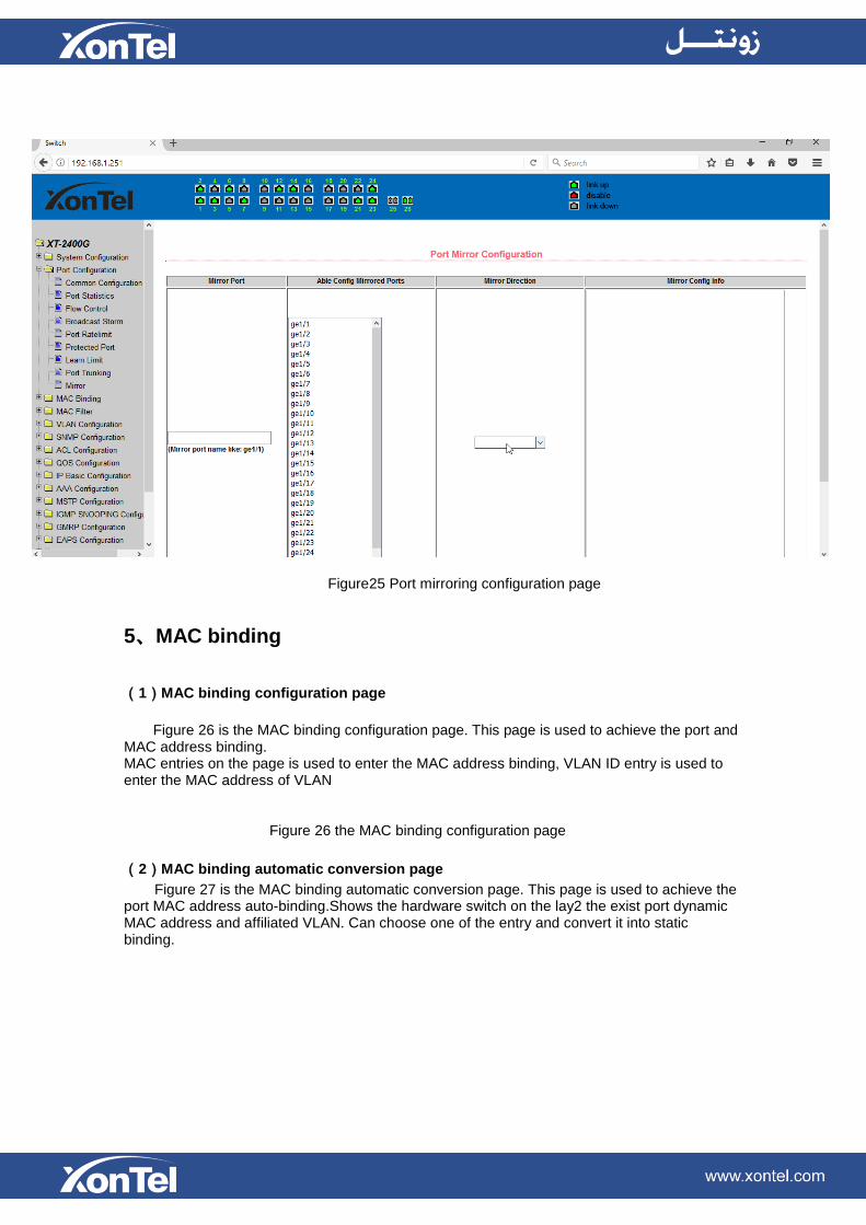
Figure25 Port mirroring configuration page
5、MAC binding
(1)MAC binding configuration page
Figure 26 is the MAC binding configuration page. This page is used to achieve the port and
MAC address binding. MAC entries on the page is used to enter the MAC address binding, VLAN ID entry is used to enter the MAC address of VLAN
Figure 26 the MAC binding configuration page
(2)MAC binding automatic conversion page
Figure 27 is the MAC binding automatic conversion page. This page is used to achieve the port MAC address auto-binding.Shows the hardware switch on the lay2 the exist port dynamic MAC address and affiliated VLAN. Can choose one of the entry and convert it into static binding.

Figure 27 the MAC binding automatic conversion page
6、MAC filtering
(1)MAC filtering configuration page
Figure 28 is the MAC filtering configuration page. This page is used to configure the ports on the MAC address filtering. MAC entries on the page is used to enter the MAC address filtering, VLAN ID entry is used to enter the MAC address affiliated VLAN.
Figure 28 the MAC filtering configuration page
(2)MAC filtering automatic conversion page
Figure 29 is the MAC filtering automatic conversion page. This page is used to achieve the
port MAC address auto-binding. Shows the hardware switch on the lay2 the exist port dynamic MAC address and affiliated VLAN. Can choose one of the entry and convert it into static filtering configuration

Figure 29 the MAC filtering automatic conversion page
7、VLAN Configuration
(1)VLAN information page
Figure 30 shows the current VLAN information page. This page is read-only page displays the current VLAN configuration information l, including the VID, state and port members. select VLAN from the drop-down VID, shows the port information of the Port VLAN members. A port may not be a member of VLAN, which can be VLAN-tagged or untagged members . the meanings of characters pls see the following info:
t tagged the port is the VLAN tagged member u untagged the port is the VLAN untagged member
Figure 30 VLAN information page
(2)Static VLAN configuration page
Figure 31 is the static VLAN configuration page that allows users to create VLAN. If you want to create a new VLAN, the user input VID on activity line, ranging from 2 to
4094. VLAN name is generated depend on VLAN ID and can not be modified. Click Apply button, then the list box displays the user-created VLAN's VID and VLAN name. Switch by default created VLAN1, and VLAN1 can not be removed
If you want to delete a VLAN, the user need to click the appropriate VLAN of the list box. The VLAN will be displayed in the activity line, click the Remove (Delete) key to delete the VLAN, the same time, the information of the VLAN to remove from the list box.
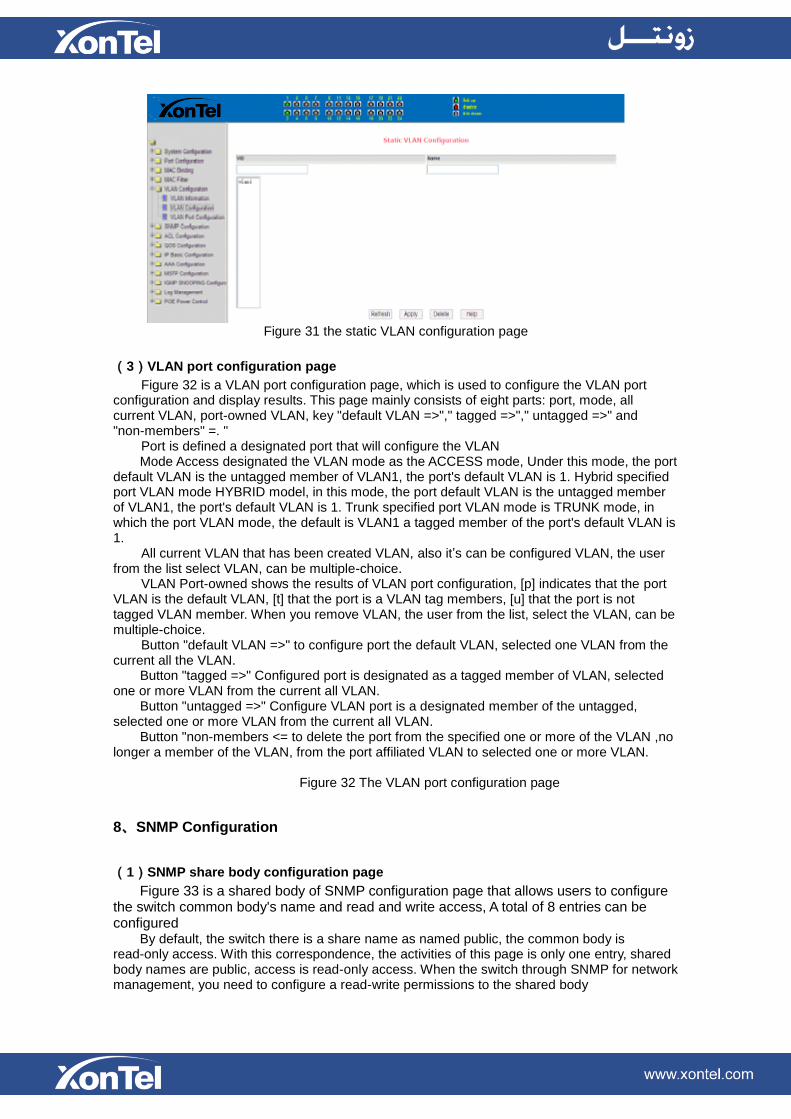
Figure 31 the static VLAN configuration page
(3)VLAN port configuration page
Figure 32 is a VLAN port configuration page, which is used to configure the VLAN port configuration and display results. This page mainly consists of eight parts: port, mode, all current VLAN, port-owned VLAN, key "default VLAN =>"," tagged =>"," untagged =>" and "non-members" =. "
Port is defined a designated port that will configure the VLAN Mode Access designated the VLAN mode as the ACCESS mode, Under this mode, the port
default VLAN is the untagged member of VLAN1, the port's default VLAN is 1. Hybrid specified port VLAN mode HYBRID model, in this mode, the port default VLAN is the untagged member of VLAN1, the port's default VLAN is 1. Trunk specified port VLAN mode is TRUNK mode, in which the port VLAN mode, the default is VLAN1 a tagged member of the port's default VLAN is 1.
All current VLAN that has been created VLAN, also it’s can be configured VLAN, the user from the list select VLAN, can be multiple-choice.
VLAN Port-owned shows the results of VLAN port configuration, [p] indicates that the port VLAN is the default VLAN, [t] that the port is a VLAN tag members, [u] that the port is not tagged VLAN member. When you remove VLAN, the user from the list, select the VLAN, can be multiple-choice.
Button "default VLAN =>" to configure port the default VLAN, selected one VLAN from the current all the VLAN. Button "tagged =>" Configured port is designated as a tagged member of VLAN, selected one or more VLAN from the current all VLAN. Button "untagged =>" Configure VLAN port is a designated member of the untagged, selected one or more VLAN from the current all VLAN. Button "non-members <= to delete the port from the specified one or more of the VLAN ,no longer a member of the VLAN, from the port affiliated VLAN to selected one or more VLAN.
Figure 32 The VLAN port configuration page
8、SNMP Configuration
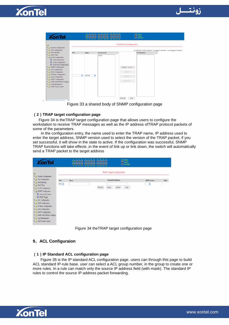
(1)SNMP share body configuration page
Figure 33 is a shared body of SNMP configuration page that allows users to configure the switch common body's name and read and write access, A total of 8 entries can be configured
By default, the switch there is a share name as named public, the common body is read-only access. With this correspondence, the activities of this page is only one entry, shared body names are public, access is read-only access. When the switch through SNMP for network management, you need to configure a read-write permissions to the shared body
.
Figure 33 a shared body of SNMP configuration page
(2)TRAP target configuration page
Figure 34 is theTRAP target configuration page that allows users to configure the workstation to receive TRAP messages as well as the IP address ofTRAP protocol packets of some of the parameters.
In the configuration entry, the name used to enter the TRAP name, IP address used to enter the target address, SNMP version used to select the version of the TRAP packet, if you set successful, it will show in the state to active. If the configuration was successful, SNMP TRAP functions will take effects ,in the event of link up or link down, the switch will automatically send a TRAP packet to the target address
Figure 34 theTRAP target configuration page
9、ACL Configuraion
(1)IP Standard ACL configuration page
Figure 35 is the IP standard ACL configuration page. users can through this page to build ACL standard IP-rule base. user can select a ACL group number, in the group to create one or more rules. In a rule can match only the source IP address field (with mask). The standard IP rules to control the source IP address packet forwarding.

Figure 35 the IP standard ACL configuration page
Users to configure the rules, the source IP address must be in with a mask, the rule can match the collection of IP addresses. The address mask is use anti-code , if the rule were to match the IP address range 192.168.0.0 to 192.168.0.255, then the IP address can be 192.168.0.1, and its mask of 0.0.0.255.
Users to configure the rules, each rule must have a filter mode: allow or deny. The user to create a rule in the group, the system will automatically give the rule a rule number, when to delete a rule in the group 1 rules, other rules remain unchanged, the system will automatically give the rule a rule group sort. If the user wants to delete the entire rule set, you can first select all, then click the delete key.
(2)IP Extended ACL configuration page
Figure 36 is the IP extended ACL configuration page. The extended IP group is an extension of the standard IP rules. Control the packet forwarding via source IP, Destination IP, IP protocol type and service port.
Figure 36 the IP Extended ACL configuration page
(3)MAC IP ACL configuration page
Figure 37 is the MAC IP ACL configuration page. IP MAC group can be the IP packet source and destination MAC address and source and destination IP address control.
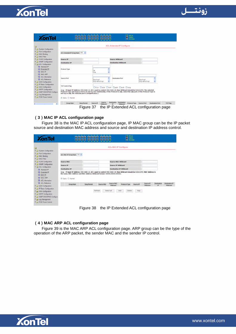
Figure 37 the IP Extended ACL configuration page
(3)MAC IP ACL configuration page
Figure 38 is the MAC IP ACL configuration page, IP MAC group can be the IP packet source and destination MAC address and source and destination IP address control.
Figure 38 the IP Extended ACL configuration page
(4)MAC ARP ACL configuration page
Figure 39 is the MAC ARP ACL configuration page. ARP group can be the type of the operation of the ARP packet, the sender MAC and the sender IP control.
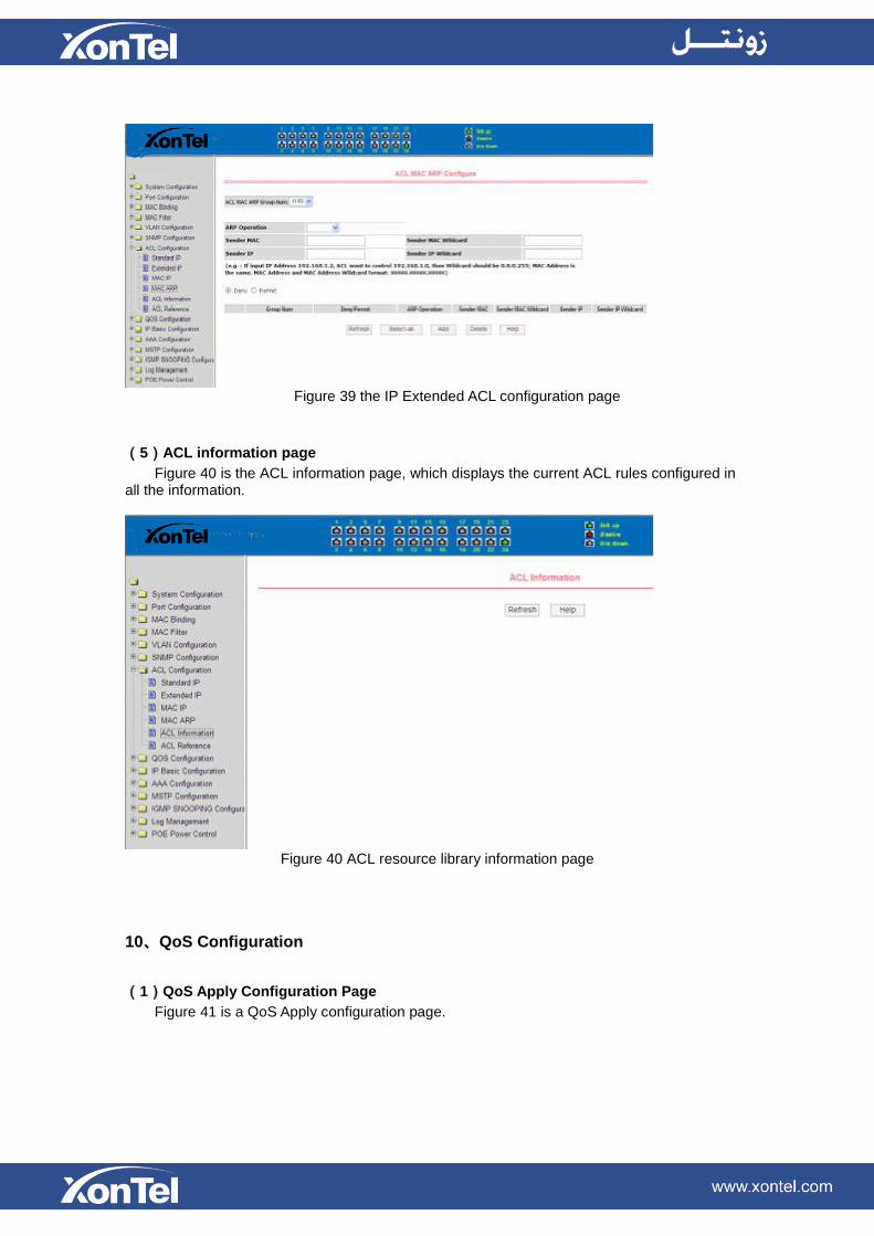
Figure 39 the IP Extended ACL configuration page
(5)ACL information page
Figure 40 is the ACL information page, which displays the current ACL rules configured in all the information.
Figure 40 ACL resource library information page
10、QoS Configuration
(1)QoS Apply Configuration Page
Figure 41 is a QoS Apply configuration page.

Figure 41 QoS Apply configuration page
(2)QoS Schedule Configuration Page
Figure 42 is a QoS Schedule configuration page.
Figure 42 QoS Schedule configuration page
11、IP Basic Configuration
(1)VLAN Interface Configuration Page
Figure 43 is a VLAN interface configuration page, users can configure the VLAN interface through this page, delete VLAN interfaces, configure the interface IP address, remove the interface IP address, and view interface information. VLAN already exists can only be set when the interface can only be configured on the interface set interface address.

Figure 43 VLAN interface configuration page
XonTel switch in the default have a VLAN1 interface, the interface can not be deleted. One
can only configure a VLAN interface.
(2)ARP configuration and display page
Figure 44 is the ARP configuration and display page, this page can display all of the information of the ARP table switch, while users can configure a static ARP entries on this page, delete ARP entries, and revised the dynamic ARP table entry to a static ARP table entry.
When a user configure a static ARP entry, the need to enter the IP address and MAC address, MAC address must be a unicast MAC address, and then click Add button.
When a user delete an ARP entry, you can choose to delete an IP-ARP table entry, remove a segment of the ARP table entry, delete all of the ARP table entry, delete all dynamic ARP table entries and delete all of the static ARP table entry . For the deletion of an IP-ARP table entries, or delete a segment of the ARP table entry required to enter in the input box, specify the IP address or IP network segment. Then click the Delete button
When dynamic ARP table entry was revised to a static ARP table entry, you can choose to a particular network segment or all of the dynamic ARP table entry was revised to a static ARP table entry. For the situation to a network segment is required in the input box, enter the specified network segment. And then click Apply button
Figure 44 the ARP configuration and display page
(3)Host Static Routing configuration page
Figure 45 is the host static route configuration page, the user can through this page to add, delete static routing switch hosts. By default, the XonTel XT-1600/XT-2400 switch is not configured to host a static route, the user can configure the default route through this page, that

is the purpose of address / subnet prefix is 0.0.0.0 / 0 routing
Figure 45 the host static route configuration page
12、Certification. Authorization. Accounting (AAA) configuration
(1)Radius Configuration Page
Figure 46 is the Radius configuration page, users can configure with the Radius-related information, you can set information includes: 1. Be sure to set the Radius server's IP address before do the authentication and accounting in this field,
2. Optional Radius server IP address, if there is spare Radius server can set this field.
3. Authentication UDP port, the default value is 1812, the user generally do not need to modify this field.
4. whether to activate the, the default is to start, and when you do authentication and accounting in general to start charging.
5. Accounting UDP port, the default value is 1813.
6.shared secret key is used to setting the shared encryption password between the switch and the Radius server, so be sure to set the authentication and accounting in this field, and with the same settings on the Radius server.
7. vendor-specific information, the users typically do not need to modify this field.
8. NAS ports, NAS port type, NAS type of service, these three values do not change in general. 9. whether to on or off the roaming feature of Radius.
Figure 46 the Radius configuration page

(2)802.1x Configuration Page
Figure 47 is the 802.1x configuration page, users can configure 802.1x related
information on this page, including:
1. whether to activate the 802.1x protocol, when doing authentication and accounting must be to start 802.1x protocol. 2. switch is to adopt a common authentication method or the expansion of authentication.
3. whether to open re-authentication function, the default is not open .when you do authentication and accounting based on the actual circumstances. Open the re-authentication feature will make users more reliable when using the authentication and accounting, but it will slightly increase the network traffic.
4. Setting re-certification time interval, only to re-open the case of authentication to be valid, the default is 3600 seconds, when you do authentication and accounting based on the actual situation to set the value, but the value is not too small.
5. Quiet Period Timer, users typically do not need to modify this field.
6. Tx-Period Timer, userstypically do not need to modify this field.
7. Server timeout timer, users typically do not need to modify this field.
8.supplicant timeout timer, users typically do not need to modify this field.
9. Max Request number, users generally do not need to modify this field.
10.showing Reauth Max size. 11. Client Version, the client version number. 12.Check Client, whether the certification passed then examine the client's regular flow of packets.
Figure 47 the 802.1x configuration page
(3)802.1x port configuration page
Figure 48 is the 802.1x port configuration page, the user through this page to configeure the support 802.1x port mode and hosts of the largest, at the same time you can view each port 802.1x configuration. 802.1x port model includes four types: N / A State, Auto state, Force-authorized state and Force-unauthorized state. When a port needs to do 802.1x Authentication,need to set Auto state, if not do authentication to access the network, to set N / A state, the other two states are rarely used in practical applications

Figure 48 the 802.1x port configuration page
Doing 802.1x authentication, port access, the default maximum host number is 100, the
user can modify this field, the biggest support to the 100. (4) 802.1x user authentication information page Figure 49 is a 802.1x user authentication information page, the user can see through this page, under a certain port access for all users of the state information,
Figure 49 802.1x user authentication information page
13、PoE port configuration
(1)PoE port Configuration Page
Figure 50 is the PoE port configuration / PoE-display page. Users can enable or disable the port's PoE function to the page, or View all ports of PoE information. Information can be seen in the following tables:
1, Staus: Enalbe means PoE function is available;Disable means PoE function is
close.
2, Operation: Displays the PoE ports ON or OFF

Figure 50 the PoE port configuration page