Embed Size (px)
DESCRIPTION
detector
Citation preview
XNX™ specificatioNs
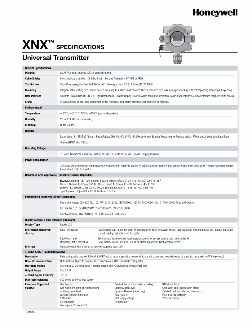
Universal transmitterGeneral Specifications
Material LM25 Aluminum, painted (SS316 painted optional)
Cable Entries 5 conduits/cable entries – (2 right, 2 left, 1 bottom) Available in ¾” NPT, or M25
Termination Cage Clamp pluggable Terminal Blocks with retaining screws, 0.5 to 2.5mm (12-28 AWG)
Mounting Integral cast mounting tabs provide secure mounting to surfaces and channel. Can be mounted to 2 to 6 inch pipe or ceiling with corresponding mounting kit (optional)
User interface Standard Custom Backlit LCD. 2.5” High Resolution DOT Matrix Display. Discrete Alarm and Status indication. Reliable Non-Intrusive 4 button interface magnetic wand access.
Signal 0-22mA analog current loop output with HART (version 6) compatible standard. Optional relay or Modbus.
Environmental
Temperature -40°C to +65°C / -40°F to +150°F (sensor dependent)
Humidity 20 to 90% RH non-condensing
IP Rating NEMA 4X IP66
Options
Relay Option 3 - SPDT (2 Alarm, 1 Fault) Relays; 250 VAC 5A, 24VDC 5A (Resistive) with External Reset Input or Modbus option: RTU protocol; selectable Baud Rate
Optional HART with IS Port
Operating Voltage
18-24 VDC Nominal (EC & mV units 16-32 VDC; IR units 18-32 VDC (Class 2 supply required)
Power Consumption
XNX used with: electrochemical sensor: 6.2 watts; millivolt (catalytic bead or IR cell): 6.5 watts; point Infrared sensor (Searchpoint Optima): 9.7 watts; open-path Infrared (Searchline Excel): 13.2 watts
Hazardous Area Approvals (Transmitter/Sensor Dependent)
UL, cUL classified: UL 1203 and 913 Seventh edition; CSA, CSA 22.2 No. 30, CSA 22.2 No. 157 Class 1, Division 1, Groups B, C, D / Class 1, Zone 1, Groups IIB + H2 T4 Tamb -40c to 65c DEMKO* IEC 60079-0, 4th ED; IEC 60079-15th Ed; IEC 60079-11 5th Ed. NCC INMETRO* Type Approval: EX [ia]d IIB + H2 T4 Tamb -40c to 65c
Performance Approvals (Sensor Dependent)
Flammable gases: CSA 22.2 No. 152, FM* 6310, 6320, DEKRA/EXAM* IEC/EN 60079-29-1, EN 61779-4:2000 Toxic and Oxygen
FM* ISA 92.0.01; DEKRA/EXAM* EN 45544:2000, EN 50104: 1999
Functional Safety: TUV EN 61508 SIL 2 Component Certification
Display Module & User Interface (Standard)
Display Type Backlit LCD
Information Displayed Base Information: Gas Reading; Gas Name and Units of measurement; Fault and Alarm Status; Large Numeric concentration or LEL display; Bar graph showing current reading, set points and full scale.
Fault/Alarm and Security settings allow multi level operator access for set-up, configuration and calibration Operating Status Indication: Event history stores Time and Date of all Alarm, Diagnostic, Configuration events
Interface Magnetic wand with terminal screwdriver (supplied each unit)
4-20mA & HART (Standard Supply)
Description Fully configurable isolated 4-20mA & HART output module providing current sink, current source and isolated modes of operation. (supports HART 6.0 protocol)
Non-intrusive Interface Optional local IS port to enable HOT connection of a HART handheld configurator
Operating Modes Current sink / Current source / Isolated current sink /Conventional or with HART data
Output Range 0 to 22mA
4-20mA Signal Accuracy +/- 1% FS
Max loop resistance 600 Ohms at 24Vdc loop supply
Functions Supported Gas Reading Detailed Sensor Information Including: RTC (Excel Only)via HART Gas Name and Units of measurement Optical Signal Level Calibration and Configuration status 4-20mA signal level Dynamic Reserve (Excel Only) Detailed Fault and Warning Information General/Device Information Raw reading Fault and Alarm History Installation 24V supply voltage Zero Calibration Configuration Temperature Forcing of 4-20mA output
* pending
© 2009 Honeywell Analytics
Local IS HART Port (Optional)
Description Provides externally accessible IS connections to the XNX transmitter to enable HOT connection of HC275/375 HART or equivalent hand held configurator.
Installation Fitted to one of the cable entries on the XNX transmitter.
Environmental Protection Terminals protected by cover to IP 66 when not in use
Relay Module (Optional)
Description Provides three fully user configurable relay outputs that can be switched based on the current gas level and/or status of the transmitter. Provides 2 x SPCO alarm and 1 x SPCO fault relays. Single Pole Double Throw SPDT. Option PCB Factory installed in display module.
Installation Fitted into housing base either at the factory or in the field by qualified service engineer.
Rating Maximum: 240 VAC, 5A (non inductive load) / 24 VDC 5A CES Minimum: 5V, 10mA (non inductive load)
Electrical Connections Fault: Common, Normally Open, Normally Closed Alarm 1: Common, Normally Open, Normally Closed Alarm 2: Common, Normally Open, Normally ClosedConfiguration Default Configurable Options
Fault Relay: Fault Relay: Normally energized Normally energized / normally de-energized Non latching None Signal inhibit as fault Enable/disable
Alarm 1 / 2 Relays: A1 / A2 Relays: Normally de-energized Normally energized / de-energized Non latching Latching / non latching Alarm rising on gas reading Alarm on rising / falling Alarm level 20% and 40% of scale Alarm level 10% to 90% of full scale Hysteresis of 2% of scale
Re-setting of Latched Relays Easily accessible interface on display (if used) or via HART interface (local or remote)
Note Use of the Relay Module or ‘Other’ Communications Module (E.g. Foundation Fieldbus) is mutually exclusive. However, relay function may be used in conjunction with standard communication output i.e. 4-20mA with HART.
Relay Specific Functions via Relay status information / Reset of latched conditions / Configuration of relays Forcing of relay stateHART Interface Reset through non intrusive User Interface. Remote Switch closure using Remote Reset input Remotely through HART
Modbus RTU Module (Optional)
Description The Modbus output module provides an Isolated RS485 output to enable the connection of the XNX transmitter to a multi-drop Modbus network
Installation Fitted into housing base either at the factory or in the field by qualified service engineer.
Connections RS485+, RS485-, Drain
Physical Layer Isolated RS485, 1200 to 19.2K Baud
Maximum No. of Nodes 254 XNX compatible transmitters only
Protocol Modbus RTU
Functions Supported As per Foundation Fieldbus Module (Optional) - see above Foundation Fieldbus Module (Optional)
Description Foundation Fieldbus compliant digital communications interface enables connection of the XNX transmitter to a multi-drop Foundation Fieldbus H1 network.
Installation Fitted into housing base either at the factory or in the field by qualified service engineer.
Connections Sig+, Sig- and Screen
Physical Layer Conforms to IEC 1158-2 and ISA 50.02, 31.25Kbits/s
Maximum No. of Nodes 32
Functions Supported Gas Reading Detailed Sensor Information Including: Detailed Fault and Warning Information: Gas Name and Units of measurement Optical Signal Level Fault and Alarm History Instrument status (OK, warning, fault, over-range) Dynamic Reserve (Excel Only) Zero Calibration General/Device Information Raw reading Remote zero and span calibration (detector dependent) 24V supply voltage Temperature RTC (Excel Only) Calibration and Configuration status
Further information is available upon request.
* Not available at time of publication. Please call your Honeywell Analytics sales person.
XNXTM is a registered trademark of Honeywell International.
HART® is a registered trademark of the HART Communication Foundation.
MODBUS® is a registered trademark of Schneider Automation Inc.
FoundationTM is a trademark of Fieldbus Foundation.