Embed Size (px)
Citation preview
Working Draft 1.0.1, September 2007
XML Paper 1
Specification 2
3
XPS Specification and Reference Guide 4
5
6
7
Base Document, Working Draft 1.0.1 8
Submitted to Ecma TC46 by Microsoft 9
September 2007 10
11
12
13
This document is "a work in progress". It is the starting point of discussions within Ecma 14
Technical Committee TC46. It was adapted from the original XPS specification as published by 15
Microsoft, to match standards editing style guidelines more closely, especially in the area of 16
distinguishing between normative and informative text. 17
A number of formatting and textual issues remain to be addressed, as well as the bulk of the 18
work of TC46 in amending the text to meet the scope and goals of the committee. Comments 19
on this draft are very welcome; this early version is provided to enable the consistent use of 20
clause and subclause references in those comments. 21
22


XPS Specification and Reference Guide Contents
Working Draft 1.0.1, September 2007 iii
Contents 1
1. SCOPE ............................................................................................................... 1 2
2. CONFORMANCE ................................................................................................... III 3
3. NORMATIVE REFERENCES ......................................................................................... V 4
4. DEFINITIONS .................................................................................................... VII 5
5. NOTATIONAL CONVENTIONS ................................................................................... XI 6
6. ACRONYMS AND ABBREVIATIONS ........................................................................... XIII 7
7. GENERAL DESCRIPTION ........................................................................................ 15 8
8. XPS DOCUMENT FORMAT ..................................................................................... 15 9
8.1 How This Specification Is Organized .............................................................. 16 10
8.2 Package ........................................................................................................ 18 11
9. PARTS AND RELATIONSHIPS .................................................................................. 19 12
9.1 Fixed Payload ................................................................................................ 19 13 9.1.1 Fixed Payload Relationships ................................................................................... 22 14
9.1.2 FixedDocumentSequence Part ................................................................................ 23 15 9.1.3 FixedDocument Part ............................................................................................. 24 16
9.1.4 FixedPage Part .................................................................................................... 24 17 9.1.5 Image Parts ........................................................................................................ 24 18
9.1.6 Thumbnail Parts .................................................................................................. 30 19
9.1.7 Font Parts .......................................................................................................... 31 20 9.1.8 Remote Resource Dictionary Parts .......................................................................... 36 21
9.1.9 PrintTicket Parts .................................................................................................. 36 22
9.1.10 SignatureDefinitions Part ................................................................................. 38 23 9.1.11 DocumentStructure Part .................................................................................. 38 24
9.1.12 StoryFragments Part ....................................................................................... 39 25
9.2 Part Naming Recommendations ..................................................................... 40 26
9.3 XPS Document Markup .................................................................................. 42 27 9.3.1 Support for Versioning and Extensibility .................................................................. 43 28
9.3.2 XML Usage ......................................................................................................... 43 29
9.3.3 Markup Model ..................................................................................................... 44 30 9.3.4 Whitespace ......................................................................................................... 47 31
9.3.5 Language ........................................................................................................... 47 32
10. DOCUMENTS .................................................................................................... 49 33
10.1 <FixedDocumentSequence> Element ............................................................. 49 34 10.1.1 <DocumentReference> .................................................................................... 49 35
10.2 <FixedDocument> Element ........................................................................... 50 36 10.2.1 <PageContent> Element .................................................................................. 50 37
10.2.2 <PageContent.LinkTargets> Element ................................................................. 51 38 10.2.3 <LinkTarget> Element ..................................................................................... 52 39
10.3 <FixedPage> Element ................................................................................... 53 40 10.3.1 BleedBox Attribute .......................................................................................... 54 41 10.3.2 ContentBox Attribute ....................................................................................... 55 42
10.3.3 Page Size Terminology ..................................................................................... 55 43 10.3.4 Media Orientation and Scaling ........................................................................... 56 44
10.4 <Canvas> Element ........................................................................................ 61 45
10.5 <Path> Element ............................................................................................ 65 46

Contents XPS Specification and Reference Guide
4 Working Draft 1.0.1, September 2007
10.6 <Glyphs> Element ......................................................................................... 65 1
11. GRAPHICS....................................................................................................... 67 2
11.1 <Path> Element ............................................................................................ 68 3 11.1.1 <Path.Data> Element ..................................................................................... 74 4
11.1.2 <Path.Fill> Element ........................................................................................ 75 5 11.1.3 <Path.Stroke> Element ................................................................................... 76 6
11.2 Geometries and Figures ................................................................................. 77 7 11.2.1 Geometries .................................................................................................... 78 8
11.2.2 Figures ......................................................................................................... 81 9
11.2.3 Abbreviated Geometry Syntax .......................................................................... 90 10
12. TEXT ............................................................................................................. 97 11
12.1 <Glyphs> Element ......................................................................................... 98 12 12.1.1 Glyph Metrics ................................................................................................ 104 13
12.1.2 Mapping Code Units to Glyphs ......................................................................... 105 14 12.1.3 Indices Attribute ........................................................................................... 109 15
12.1.4 UnicodeString Attribute .................................................................................. 111 16
12.1.5 StyleSimulations Attribute............................................................................... 112 17 12.1.6 IsSideways Attribute ...................................................................................... 112 18
12.1.7 DeviceFontName Attribute .............................................................................. 118 19 12.1.8 xml:lang Attribute ......................................................................................... 119 20
12.1.9 CaretStops Attribute ...................................................................................... 119 21
12.1.10 Optimizing Glyph Markup ................................................................................ 120 22 12.1.11 Glyph Markup Examples .................................................................................. 121 23
12.2 <Glyphs.Fill> Element ................................................................................. 124 24
13. BRUSHES ...................................................................................................... 125 25
13.1 <SolidColorBrush> Element......................................................................... 126 26
13.2 <ImageBrush> Element .............................................................................. 127 27
13.3 <VisualBrush> Element ............................................................................... 131 28 13.3.1 <VisualBrush.Visual> Element ......................................................................... 133 29
13.4 Common Attributes for Tiling Brushes ......................................................... 136 30 13.4.1 Viewbox, Viewport, ViewboxUnits, and ViewportUnits Attributes ............................ 136 31
13.4.2 TileMode Attribute ......................................................................................... 141 32
13.5 <LinearGradientBrush> Element ................................................................. 151 33 13.5.1 SpreadMethod Attribute .................................................................................. 154 34
13.5.2 <LinearGradientBrush.GradientStops> Element .................................................. 157 35
13.6 <RadialGradientBrush> Element ................................................................. 158 36 13.6.1 SpreadMethod Attribute .................................................................................. 162 37
13.6.2 <RadialGradientBrush.GradientStops> Element .................................................. 165 38
13.7 <GradientStop> Element ............................................................................. 166 39
13.8 Using a Brush as an Opacity Mask ............................................................... 167 40
14. COMMON PROPERTIES ...................................................................................... 171 41
14.1 Opacity ....................................................................................................... 172 42
14.2 Resources and Resource References ............................................................ 172 43 14.2.1 <FixedPage.Resources> Element ..................................................................... 173 44 14.2.2 <Canvas.Resources> Element ......................................................................... 175 45
14.2.3 <ResourceDictionary> Element ........................................................................ 176 46 14.2.4 Resource References ...................................................................................... 180 47
14.2.5 Scoping Rules for Resolving Resource References ............................................... 180 48
14.2.6 Support for Markup Compatibility ..................................................................... 181 49
14.3 Clipping ....................................................................................................... 182 50 14.3.1 <Canvas.Clip> Element .................................................................................. 182 51

XPS Specification and Reference Guide Contents
Working Draft 1.0.1, September 2007 v
14.3.2 <Path.Clip> Element ..................................................................................... 183 1 14.3.3 <Glyphs.Clip> Element .................................................................................. 184 2
14.4 Positioning Content ..................................................................................... 185 3 14.4.1 <MatrixTransform> Element ........................................................................... 185 4 14.4.2 <Canvas.RenderTransform> Element ............................................................... 189 5
14.4.3 <Path.RenderTransform> Element ................................................................... 190 6
14.4.4 <Glyphs.RenderTransform> Element ............................................................... 191 7 14.4.5 <PathGeometry.Transform> Element ............................................................... 192 8
14.4.6 <ImageBrush.Transform> Element .................................................................. 193 9
14.4.7 <VisualBrush.Transform> Element .................................................................. 194 10 14.4.8 <LinearGradientBrush.Transform> Element ....................................................... 197 11
14.4.9 <RadialGradientBrush.Transform> Element ....................................................... 198 12
14.5 OpacityMask ................................................................................................ 200 13 14.5.1 <Canvas.OpacityMask> Element ..................................................................... 200 14 14.5.2 <Path.OpacityMask> Element ......................................................................... 201 15
14.5.3 <Glyphs.OpacityMask> Element ...................................................................... 202 16
15. COLOR ......................................................................................................... 205 17
15.1 Color Support .............................................................................................. 205 18 15.1.1 sRGB Color Space ......................................................................................... 205 19
15.1.2 scRGB Color Space ........................................................................................ 206 20
15.1.3 Gray Color Space .......................................................................................... 206 21 15.1.4 CMYK Color Space ......................................................................................... 206 22
15.1.5 N-Channel Color Spaces ................................................................................. 206 23 15.1.6 Named Color for Spot Colors and N-tone Images ................................................ 206 24
15.1.7 Device Color Spaces ...................................................................................... 206 25
15.1.8 ICC Profiles.................................................................................................. 206 26 15.1.9 WcsProfilesTag ............................................................................................. 207 27
15.1.10 WCS Color Profiles ........................................................................................ 208 28 15.1.11 Vector Color Syntax ...................................................................................... 208 29
15.1.12 sRGB Color Syntax ........................................................................................ 209 30
15.1.13 scRGB Color Syntax ...................................................................................... 209 31
15.1.14 CMYK Color Syntax ....................................................................................... 210 32 15.1.15 N-Channel Color Syntax ................................................................................. 210 33
15.1.16 Named Color Syntax...................................................................................... 212 34
15.2 Rich Colors in Raster Images ....................................................................... 213 35 15.2.1 sRGB Raster Images ...................................................................................... 213 36
15.2.2 scRGB Raster Images .................................................................................... 214 37
15.2.3 Gray Raster Images ...................................................................................... 214 38 15.2.4 CMYK Raster Images ..................................................................................... 215 39
15.2.5 N-channel Raster Images ............................................................................... 215 40 15.2.6 Named Color Raster Images ........................................................................... 216 41
15.2.7 Device Color Raster Images ............................................................................ 216 42
15.2.8 Images and Color Profile Association ................................................................ 216 43 15.2.9 Color Space Pixel Formats for Raster Images ..................................................... 216 44
15.3 Color Separation .......................................................................................... 217 45
15.4 Alpha and Gradient Blending with Rich Colors ............................................. 217 46
15.5 PrintTicket Color Settings ............................................................................ 219 47
16. DOCUMENT STRUCTURE AND INTERACTIVITY .......................................................... 223 48
16.1 Document Structure Markup ........................................................................ 223 49 16.1.1 DocumentStructure Part ................................................................................ 224 50 16.1.2 StoryFragments Part ..................................................................................... 230 51
16.2 Hyperlinks ................................................................................................... 243 52 16.2.1 Hyperlink Activation ...................................................................................... 243 53
16.2.2 Hyperlink Addressing ..................................................................................... 244 54 16.2.3 Name Attribute ............................................................................................. 245 55
16.2.4 FixedPage.NavigateUri Attribute ...................................................................... 245 56
16.3 Selection ..................................................................................................... 246 57

Contents XPS Specification and Reference Guide
6 Working Draft 1.0.1, September 2007
16.4 Accessibility ................................................................................................ 246 1 16.4.1 Reading Order ............................................................................................... 246 2
16.4.2 Screen Reader Applications ............................................................................. 247 3
16.4.3 Text Alternatives for Graphics and Images ......................................................... 247 4
17. XPS DOCUMENT PACKAGE FEATURES ................................................................... 249 5
17.1 Interleaving Optimizations .......................................................................... 249 6 17.1.1 Empty PrintTicket .......................................................................................... 251 7
17.1.2 Optimizing Interleaving Order .......................................................................... 251 8
17.1.3 Consuming Interleaved Packages ..................................................................... 255 9 17.1.4 Consumers with Resource Constraints ............................................................... 255 10
17.1.5 Interleaving Optimizations and Digital Signatures ............................................... 257 11
17.2 Digital Signatures ........................................................................................ 258 12 17.2.1 Signature Policy ............................................................................................ 258 13
17.2.2 Signature Definitions ...................................................................................... 261 14
17.3 Core Properties ........................................................................................... 265 15
18. RENDERING RULES .......................................................................................... 267 16
18.1 Coordinate System and Rendering Placement .............................................. 267 17 18.1.1 Page Dimensions ........................................................................................... 267 18
18.1.2 Rounding of Coordinates ................................................................................. 267 19
18.1.3 Transforms ................................................................................................... 268 20 18.1.4 Pixel Center Location, Pixel Placement, and Pixel Inclusion ................................... 269 21
18.1.5 Maximum Placement Error .............................................................................. 269 22 18.1.6 Pixel Placement for Glyphs .............................................................................. 269 23
18.1.7 Abutment of Shapes ....................................................................................... 269 24
18.1.8 Clipping Behavior .......................................................................................... 270 25
18.2 Implementation Limits ................................................................................ 270 26
18.3 Gradient Computations ................................................................................ 272 27 18.3.1 All Gradients ................................................................................................. 272 28
18.3.2 Linear Gradients ............................................................................................ 274 29
18.3.3 Radial Gradients ............................................................................................ 276 30
18.4 Opacity Computations ................................................................................. 279 31 18.4.1 Pre-Multiplied Alpha and Superluminous Colors ................................................... 281 32
18.5 Composition Rules ....................................................................................... 282 33 18.5.1 Optimization Guidelines .................................................................................. 283 34 18.5.2 Composition Examples.................................................................................... 284 35
18.6 Stroke Rendering ........................................................................................ 288 36 18.6.1 Stroke Edge Parallelization .............................................................................. 288 37 18.6.2 Phase Control ............................................................................................... 288 38
18.6.3 Symmetry of Stroke Drawing Algorithms ........................................................... 288 39
18.6.4 Rules for Dash Cap Rendering .......................................................................... 289 40 18.6.5 Rules for Line Cap Rendering ........................................................................... 291 41
18.6.6 Line Caps for Dashed Strokes .......................................................................... 292 42 18.6.7 Rules for Line Join Rendering ........................................................................... 293 43
18.6.8 Rules for Degenerate Line and Curve Segments .................................................. 297 44
18.6.9 Stroking and Fill Rule ..................................................................................... 298 45
18.6.10 Mixing Stroked and Non-Stroked Segments ........................................................ 298 46 18.6.11 Stroke Behavior with Multiple Path Figures ........................................................ 298 47
18.6.12 Consistent Nominal Stroke Width ..................................................................... 298 48
18.7 Brushes and Images .................................................................................... 299 49 18.7.1 Small Tiles ................................................................................................... 299 50
18.7.2 Image Scaling ............................................................................................... 299 51
18.7.3 Tile Placement .............................................................................................. 299 52 18.7.4 Tiling Transparent Visual Brushes and Image Brushes .......................................... 300 53

XPS Specification and Reference Guide Contents
Working Draft 1.0.1, September 2007 vii
19. ELEMENTS .................................................................................................... 301 1
A. SIGNATURE DEFINITIONS SCHEMA ........................................................................ 359 2
B. XPS DOCUMENT SCHEMA ................................................................................... 361 3
C. RESOURCE DICTIONARY KEY SCHEMA .................................................................... 383 4
D. DOCUMENT STRUCTURE SCHEMA .......................................................................... 385 5
E. DISCARD CONTROL SCHEMA ................................................................................ 391 6
F. ABBREVIATED GEOMETRY SYNTAX ALGORITHM ......................................................... 393 7
G. SCRGB GAMUT BOUNDARY DEFINITION ................................................................. 399 8
H. STANDARD NAMESPACES AND CONTENT TYPES ......................................................... 405 9
H.1 XML Namespace URIs .................................................................................. 405 10
H.2 Content Types ............................................................................................. 406 11
H.3 Relationship Types ...................................................................................... 407 12
I. CONFORMANCE REQUIREMENTS ............................................................................ 409 13
I.1 XPS Document Format ................................................................................. 409 14
I.2 Parts and Relationships ............................................................................... 410 15
I.3 Documents .................................................................................................. 421 16
I.4 Graphics ...................................................................................................... 423 17
I.5 Text ............................................................................................................ 424 18
I.6 Brushes ....................................................................................................... 427 19
I.7 Common Properties ..................................................................................... 428 20
I.8 Color ........................................................................................................... 429 21
I.9 Document Structure and Interactivity .......................................................... 434 22
I.10 XPS Document Package Features ................................................................. 439 23
I.11 Rendering Rules .......................................................................................... 444 24
I.12 Additional Conformance Requirements ........................................................ 450 25
J. BIBLIOGRAPHY ................................................................................................. 453 26
K. INDEX ........................................................................................................... 457 27
28


XPS Specification and Reference Guide List of Figures
Working Draft 1.0.1, September 2007 ix
List of Figures 1
Figure 8–1. Package-based XPS Document format .............................................. 18 2
Figure 10–1. Page regions ............................................................................... 56 3
Figure 10–2. Matching PrintTicket and fixed page size and orientation .................. 57 4
Figure 10–3. Matching PrintTicket and fixed page size with differing orientation ..... 57 5
Figure 10–4. Matching PrintTicket and fixed page orientation with differing size ..... 58 6
Figure 11–1. Fill using EvenOdd algorithm ......................................................... 80 7
Figure 11–2. Fill using NonZero algorithm ......................................................... 80 8
Figure 11–3. Arc choice A ................................................................................ 84 9
Figure 11–4. Arc choice B ................................................................................ 84 10
Figure 11–5. Arc choice C ................................................................................ 84 11
Figure 11–6. Arc choice D ............................................................................... 84 12
Figure 12–1. Glyph metrics ........................................................................... 104 13
Figure 12–2. Upright (usually horizontal) glyph metrics ..................................... 104 14
Figure 12–3. Sideways (usually vertical) glyph metrics ..................................... 105 15
Figure 17–1. A sample signature spot ............................................................. 264 16
Figure 18–2. Extreme curvatures and dash rendering ....................................... 288 17
Figure 18–3. Flat dash caps ........................................................................... 289 18
Figure 18–4. Square dash caps ...................................................................... 290 19
Figure 18–5. Round dash caps ....................................................................... 290 20
Figure 18–6. Triangular dash caps .................................................................. 291 21
Figure 18–7. Overlapping dash segments ........................................................ 291 22
Figure 18–8. Flat start line cap, flat end line cap .............................................. 292 23
Figure 18–9. Square start line cap, square end line cap .................................... 292 24
Figure 18–10. Triangular start line cap, triangular end line cap .......................... 292 25
Figure 18–11. Round start line cap, round end line cap ..................................... 292 26
Figure 18–12. Stroke start or end point within a dash ....................................... 292 27
Figure 18–13. Stroke start or end point within a gap ........................................ 292 28
Figure 18–14. Round line join with right angle ................................................. 293 29
Figure 18–15. Round line join with acute angle ................................................ 293 30

List of Figures XPS Specification and Reference Guide
10 Working Draft 1.0.1, September 2007
Figure 18–16. Round line join with obtuse angle .............................................. 294 1
Figure 18–17. Beveled line join with right angle ............................................... 294 2
Figure 18–18. Beveled line join with acute angle .............................................. 294 3
Figure 18–19. Beveled line join with obtuse angle ............................................ 295 4
Figure 18–20. Mitered line join with right angle and miter limit of 1.0 ................. 295 5
Figure 18–21. Mitered line join with acute angle and miter limit of 1.0 ................ 296 6
Figure 18–22. Mitered line join with obtuse angle and miter limit of 1.0 .............. 296 7
Figure 18–23. Mitered line join with right angle and miter limit of 2.0 ................. 296 8
Figure 18–24. Mitered line join with acute angle and miter limit of 2.0 ................ 297 9
Figure 18–25. Mitered line join with acute angle and miter limit of 10.0 .............. 297 10
11

XPS Specification and Reference Guide List of Tables
Working Draft 1.0.1, September 2007 xi
List of Tables 1
Table 9–1. XPS Document parts ....................................................................... 19 2
Table 9–2. Fixed payload relationships .............................................................. 22 3
Table 9–3. Supported JPEG APPn markers ......................................................... 25 4
Table 9–4. Support for ancillary PNG chunks ...................................................... 25 5
Table 9–5. Supported TIFF 6.0 tags .................................................................. 26 6
Table 9–6. Supported Windows Media Photo features ......................................... 30 7
Table 9–7. Guidelines for OpenType font embedding .......................................... 32 8
Table 9–8. Cmap table selection ....................................................................... 35 9
Table 11–9. Arc segment definition .................................................................. 83 10
Table 11–10. Commands ................................................................................. 91 11
Table 12–1. Glyph specifications .................................................................... 109 12
Table 12–2. Portions of the cluster specification ............................................... 110 13
Table 12–3. IsSideways and BidiLevel effects on origin placement ...................... 114 14
Table 13–1. Brush types ............................................................................... 125 15
Table 13–2. Common attributes for <ImageBrush> and <VisualBrush> elements 136 16
Table 14–1. Common property attributes ........................................................ 171 17
Table 14–2. Common property elements ......................................................... 172 18
Table 15–3. WcsProfilesTagType structure ....................................................... 207 19
Table 15–1. Syntax summary ........................................................................ 209 20
Table 15–2. Color Space Pixel Format Defaults ................................................ 216 21
Table 15–3. PrintTicket color settings ............................................................. 219 22
Table 16–1. StoryFragments part elements ..................................................... 230 23
Table 16–2. Unicode character categories ....................................................... 245 24
Table 17–1. JobDigitalSignatureProcessing PrintTicket settings .......................... 261 25
Table 18–1. Recommended minimum processing requirements .......................... 270 26
Table 18–2. Opacity computation symbols ....................................................... 279 27
Table H–1. Package-wide namespaces ............................................................ 405 28
Table H–2. XPS Document namespaces ........................................................... 405 29
Table H–3. Package-wide content types .......................................................... 406 30

List of Tables XPS Specification and Reference Guide
12 Working Draft 1.0.1, September 2007
Table H–4. XPS Document content types ......................................................... 406 1
Table H–5. Package-wide relationship types .................................................... 407 2
Table H–6. XPS Document relationship types ................................................... 407 3
Table I–1. XPS Document format MUST conformance requirements .................... 409 4
Table I–2. Parts and Relationships MUST conformance requirements .................. 410 5
Table I–3. Parts and Relationships SHOULD conformance requirements .............. 415 6
Table I–4. Parts and Relationships OPTIONAL conformance requirements ............ 419 7
Table I–5. Document MUST conformance requirements ..................................... 421 8
Table I–6. Document SHOULD conformance requirements ................................. 422 9
Table I–7. Graphics MUST conformance requirements ....................................... 423 10
Table I–8. Graphics SHOULD conformance requirements ................................... 423 11
Table I–9. Graphics OPTIONAL conformance requirements ................................ 423 12
Table I–10. Text MUST conformance requirements ........................................... 424 13
Table I–11. Text SHOULD conformance requirements ....................................... 426 14
Table I–12. Text OPTIONAL conformance requirements ..................................... 426 15
Table I–13. Brushes MUST conformance requirements ...................................... 427 16
Table I–14. Common properties MUST conformance requirements ..................... 428 17
Table I–15. Common properties OPTIONAL conformance requirements ............... 429 18
Table I–16. Color MUST conformance requirements .......................................... 429 19
Table I–17. Color SHOULD conformance requirements ...................................... 432 20
Table I–18. Color OPTIONAL conformance requirements ................................... 433 21
Table I–19. Document structure MUST conformance requirements ..................... 434 22
Table I–20. Document structure SHOULD conformance requirements ................. 435 23
Table I–21. Document structure OPTIONAL conformance requirements ............... 438 24
Table I–22. XPS Document package feature MUST conformance requirements ..... 439 25
Table I–23. XPS Document package feature SHOULD conformance requirements . 441 26
Table I–24. XPS Document package feature OPTIONAL conformance requirements27
.................................................................................................................. 443 28
Table I–25. Rendering rules MUST conformance requirements ........................... 444 29
Table I–26. Rendering rules SHOULD conformance requirements ....................... 445 30
Table I–27. Rendering rules OPTIONAL conformance requirements ..................... 448 31

XPS Specification and Reference Guide List of Tables
Working Draft 1.0.1, September 2007 xiii
Table I–28. Additional MUST conformance requirements ................................... 450 1
2


XPS Specification and Reference Guide List of Examples
Working Draft 1.0.1, September 2007 xv
List of Examples 1
Example 9–1. A typical XPS Document .............................................................. 21 2
Example 9–2. XPS Document part naming ......................................................... 42 3
Example 9–3. Property attribute syntax ............................................................ 45 4
Example 9–4. Property element syntax ............................................................. 47 5
Example 10–1. <FixedDocumentSequence> usage ............................................. 49 6
Example 10–2. <FixedDocument> usage .......................................................... 50 7
Example 10–3. <PageContent> usage .............................................................. 51 8
Example 10–4. <PageContent.LinkTargets> usage ............................................. 52 9
Example 10–5. Fixed page markup ................................................................... 54 10
Example 10–6. Canvas composition .................................................................. 64 11
Example 11–1. <Path.Data> usage .................................................................. 74 12
Example 11–2. <Path.Fill> usage ..................................................................... 76 13
Example 11–3. <Path.Stroke> usage ............................................................... 77 14
Example 11–4. <PathGeometry> usage ............................................................ 79 15
Example 11–5. <ArcSegment> usage ............................................................... 84 16
Example 11–6. <PolyBezierSegment> usage ..................................................... 86 17
Example 11–7. <PolyLineSegment> usage ........................................................ 87 18
Example 11–8. <PolyQuadraticBezierSegment> usage ....................................... 89 19
Example 11–9. Closed <PathFigure> usage ....................................................... 89 20
Example 11–10. A path described using abbreviated syntax ................................ 94 21
Example 11–11. Smooth Bézier curve ............................................................... 94 22
Example 11–12. Relative commands and curves ................................................ 95 23
Example 12–1. One-to-one cluster map .......................................................... 106 24
Example 12–2. Many-to-one cluster map ........................................................ 106 25
Example 12–3. One-to-many cluster map ....................................................... 107 26
Example 12–4. Many-to-many cluster map ...................................................... 108 27
Example 12–1. Using indices to specify advance width ...................................... 110 28
Example 12–2. Using the Indices attribute to specify glyph replacement for a cluster29
.................................................................................................................. 111 30
Example 12–3. Text with positive uOffset and vOffset Indices values .................. 115 31

List of Examples XPS Specification and Reference Guide
16 Working Draft 1.0.1, September 2007
Example 12–4. Right-to-left text (odd BidiLevel) .............................................. 115 1
Example 12–5. Sideways text (IsSideways set to true) ..................................... 116 2
Example 12–6. Vertical text ........................................................................... 116 3
Example 12–7. Japanese vertical text ............................................................. 117 4
Example 12–8. Using the CaretStops attribute to determine a valid caret stop 5
position ....................................................................................................... 119 6
Example 12–9. Basic italic font ...................................................................... 121 7
Example 12–10. Italic font using StyleSimulations attribute ............................... 121 8
Example 12–11. Kerning ............................................................................... 122 9
Example 12–12. Ligatures ............................................................................. 122 10
Example 12–13. Cluster maps ....................................................................... 123 11
Example 13–1. <SolidColorBrush> usage ........................................................ 127 12
Example 13–2. <ImageBrush> usage ............................................................. 130 13
Example 13–3. <VisualBrush.Visual> usage .................................................... 134 14
Example 13–4. ViewboxUnits and ViewportUnits attribute usage ........................ 137 15
Example 13–5. Tiling brush base image and rendering ...................................... 137 16
Example 13–6. Tiling brush Viewport adjustments ............................................ 138 17
Example 13–7. Tiling brush viewbox adjustments ............................................. 139 18
Example 13–8. Image brush with a Viewbox larger than the image .................... 140 19
Example 13–9. Image brush with TileMode value of None ................................. 141 20
Example 13–10. Visual brush with TileMode value of None ................................ 142 21
Example 13–11. Image brush with a TileMode value of Tile ............................... 143 22
Example 13–12. Visual brush with a TileMode value of Tile ................................ 144 23
Example 13–13. Image brush with a TileMode value of FlipX ............................. 145 24
Example 13–14. Visual brush with a TileMode value of FlipX .............................. 146 25
Example 13–15. Image brush with a TileMode value of FlipY .............................. 147 26
Example 13–16. Visual Brush with a TileMode value of FlipY .............................. 148 27
Example 13–17. Image brush with a TileMode value of FlipXY ............................ 149 28
Example 13–18. Visual brush with a TileMode value of FlipXY ............................ 150 29
Example 13–19. <LinearGradientBrush> usage ............................................... 153 30
Example 13–20. Linear gradient brush with a SpreadMethod value of Pad ........... 154 31
XPS Specification and Reference Guide List of Examples
Working Draft 1.0.1, September 2007 xvii
Example 13–21. Linear gradient brush with a SpreadMethod value of Reflect ....... 155 1
Example 13–22. Linear gradient brush with a SpreadMethod value of Repeat ...... 156 2
Example 13–23. A radial gradient brush .......................................................... 161 3
Example 13–24. RadialGradientBrush usage .................................................... 161 4
Example 13–25. Radial gradient brush with a SpreadMethod value of Pad ........... 162 5
Example 13–26. Radial gradient brush with a SpreadMethod value of Reflect ....... 163 6
Example 13–27. Radial gradient brush with a SpreadMethod value of Repeat ...... 164 7
Example 13–28. Opacity mask with linear gradient ........................................... 167 8
Example 13–29. Opacity mask with radial gradient ........................................... 169 9
Example 14–1. <FixedPage.Resources> usage ................................................ 173 10
Example 14–2. <Canvas.Resources> usage .................................................... 175 11
Example 14–3. Resource dictionary markup .................................................... 177 12
Example 14–4. A remote resource dictionary and reference ............................... 178 13
Example 14–5. Using a resource reference to fill a brush ................................... 180 14
Example 14–6. Using scoping rules................................................................. 181 15
Example 14–7. Canvas clip markup and rendering ............................................ 182 16
Example 14–8. <Path.Clip> usage ................................................................. 183 17
Example 14–9. <Glyphs.Clip> usage .............................................................. 184 18
Example 14–10. Matrix scaling ....................................................................... 186 19
Example 14–11. Matrix reversing the x axis..................................................... 186 20
Example 14–12. Matrix reversing the y axis..................................................... 186 21
Example 14–13. Matrix skewing ..................................................................... 186 22
Example 14–14. Matrix Rotating .................................................................... 187 23
Example 14–15. Matrix positioning ................................................................. 187 24
Example 14–16. <MatrixTransform> usage ..................................................... 187 25
Example 14–17. Using abbreviated matrix transformation syntax ....................... 189 26
Example 14–18. <Canvas.RenderTransform> usage ......................................... 189 27
Example 14–19. <Path.RenderTransform> usage ............................................. 190 28
Example 14–20. <Glyphs.RenderTransform> usage ......................................... 191 29
Example 14–21. <PathGeometry.Transform> usage ......................................... 192 30
Example 14–22. <ImageBrush.Transform> usage ............................................ 193 31

List of Examples XPS Specification and Reference Guide
18 Working Draft 1.0.1, September 2007
Example 14–23. <VisualBrush.Transform> usage ............................................ 194 1
Example 14–24. <VisualBrush.Transform> usage with tiling behavior ................. 196 2
Example 14–25. <LinearGradientBrush.Transform> usage ................................ 197 3
Example 14–26. <RadialGradientBrush.Transform> usage ................................ 198 4
Example 14–27. <Canvas.OpacityMask> usage ............................................... 200 5
Example 14–28. <Path.OpacityMask> usage ................................................... 201 6
Example 14–29. <Glyphs.OpacityMask> usage ................................................ 203 7
Example 16–1. Document structure markup .................................................... 224 8
Example 16–2. Document outline markup ....................................................... 227 9
Example 16–3. Simple multi-story document ................................................... 230 10
Example 16–4. Story flowing back and forth across a page boundary ................. 230 11
Example 16–5. Content structure spanning pages ............................................ 232 12
Example 16–6. StoryFragments part markup ................................................... 236 13
Example 16–7. Story fragments markup using a fragment name ........................ 237 14
Example 16–8. A relative, internal, named-address hyperlink ............................ 244 15
Example 16–9. A relative internal page address hyperlink ................................. 244 16
Example 17–1. Optimized interleaving for a single-threaded parsing architecture . 251 17
Example 17–2. Optimized interleaving for a multi-threaded parsing architecture .. 254 18
Example 17–3. A DiscardControl part .............................................................. 256 19
Example 17–4. A SignatureDefinitions part ...................................................... 262 20
Example 18–1. Path opacity behavior for overlapping path figures ..................... 284 21
Example 18–2. Opacity behavior of path stroke intersections ............................. 285 22
Example 18–3. Opacity behavior of paths with stroked edges ............................ 285 23
24

XPS Specification and Reference Guide Scope
Working Draft 1.0.1, September 2007 1
1. Scope 1
This specification defines XPS, the XML Paper Specification. XPS describes the set of 2
conventions for the use of XML and other widely available technologies to describe 3
the content and appearance of paginated documents. It is written for developers who 4
are building systems that process XPS content. 5
A primary goal is to ensure the interoperability of independently created software 6
and hardware systems that produce or consume XPS content. This specification 7
defines the formal requirements that producers and consumers must satisfy in order 8
to achieve interoperability. 9
This specification describes a paginated-document format called the XPS Document. 10
The format requirements are an extension of the packaging requirements described 11
in the Open Packaging Conventions (OPC) specification. That specification describes 12
packaging and physical format conventions for the use of XML, Unicode, ZIP, and 13
other technologies and specifications, to organize the content and resources that 14
make up any document. They are an integral part of the XPS specification, and are 15
included by reference. 16
Many XML-based building blocks within XPS make use of the conventions described 17
in the Markup Compatibility specification that is relied upon by the OPC specification 18
to facilitate future enhancement and extension of XPS markup. As such, that Markup 19
Compatibility specification is included by reference.20


XPS Specification and Reference Guide Conformance
Working Draft 1.0.1, September 2007 3
2. Conformance 1
Language Notes 2
In this specification, the words that are used to define the significance of each 3
requirement are written in uppercase. These words are used in accordance with their 4
definitions in RFC 2119, and their respective meanings are reproduced below: 5
MUST: This word, or the adjective ―REQUIRED‖, means that the item is an 6
absolute requirement of the specification. 7
SHOULD: This word, or the adjective ―RECOMMENDED‖, means that there may 8
exist valid reasons in particular circumstances to ignore this item, but the full 9
implications should be understood and the case carefully weighed before 10
choosing a different course. 11
MAY: This word, or the adjective ―OPTIONAL‖, means that this item is truly 12
optional. [Example: One implementation may choose to include the item 13
because a particular marketplace or scenario requires it or because it 14
enhances the product. Another implementation may omit the same item. end 15
example] 16
The words MUST NOT and SHOULD NOT are the negative forms of MUST and 17
SHOULD, respectively. There is no negative form of MAY. 18
Software Conformance 19
Most requirements are expressed as format or package requirements rather than 20
implementation requirements. 21
In order for consumers to be considered conformant, they must observe the 22
following rules: 23
They MUST NOT report errors when processing conforming instances of the 24
documented formats except when forced to do so by resource exhaustion. 25
They SHOULD report errors when processing non-conforming instances of the 26
documented formats when doing so does not pose an undue processing or 27
performance burden. 28
In order for producers to be considered conformant, they must observe the following 29
rules: 30
They MUST NOT generate any new, non-conforming instances of a 31
documented format. 32
They MUST NOT introduce any non-conformance when modifying an instance 33
of a documented format. 34
Editing applications are subject to all of the above rules. 35
Conformance requirements are documented inline in this specification, and each 36
requirement is denoted by a letter (M – MUST; S – SHOULD; O – OPTIONAL) and a 37
rule number, all enclosed in brackets ([…]). [Example: [M1.2] is a MUST 38
requirement, [S2.4] is a SHOULD requirement, and [O3.9] is a MAY requirement. 39
Comment [rcj1]: rules for consumers and producers.

Preface XPS Specification and Reference Guide
4 Working Draft 1.0.1, September 2007
end example] These rules are collected in I, ―Conformance Requirements‖ for 1
convenient reference. 2

XPS Specification and Reference Guide Normative References
Working Draft 1.0.1, September 2007 5
3. Normative References 1
The following normative documents contain provisions, which, through reference in 2
this text, constitute provisions of this specification. For dated references, subsequent 3
amendments to, or revisions of, any of these publications do not apply. However, 4
parties to agreements based on this specification are encouraged to investigate the 5
possibility of applying the most recent editions of the normative documents indicated 6
below. For undated references, the latest edition of the normative document referred 7
to applies. Members of ISO and IEC maintain registers of currently valid International 8
Standards. 9
10
ECMA-376, "Office Open XML File Formats" (December 2006), Part 2, "Open 11
Packaging Conventions", which is commonly referred to as OPC. 12
ECMA-376, "Office Open XML File Formats" (December 2006), Part 5, "Markup 13
Compatibility and Extensibility". 14
ISO/IEC 2382.1:1993, Information technology — Vocabulary — Part 1: Fundamental 15
terms. 16
ISO/IEC 10646:2003 (all parts), Information technology — Universal Multiple-Octet 17
Coded Character Set (UCS).18


XPS Specification and Reference Guide Definitions
Working Draft 1.0.1, September 2007 7
4. Definitions 1
For the purposes of this specification, the following definitions apply. Terms explicitly 2
defined in this specification are not to be presumed to refer implicitly to similar terms 3
defined elsewhere. 4
alpha blending — Transparently blending two elements when rendering. 5
broken digital signature — A digital signature that conforms to the XPS Document 6
signing rules but does not meet the digital signature validity requirements due to 7
incorrect hash calculation or similar problems. 8
Compliant digital signature — A digital signature that conforms to the signing 9
rules described in the XPS Document signing policy, regardless of signature validity. 10
consumer — A piece of software or a device that reads XPS packages. 11
content structure — The set of markup elements that allow expression of well-12
understood semantic blocks such as paragraphs, tables, lists, and figures. 13
content type — Describes the type of content stored in a part. Content types define 14
a media type, a subtype, and an optional set of parameters, as defined in RFC 2045. 15
contour intersection point — The intersection of the flat line ending a dash and 16
the contour of the shape. 17
device — A piece of hardware, such as a printer or scanner, that performs a single 18
function or a set of functions. 19
document content — A document structural concept that identifies each block of 20
individually readable content in an XPS Document. 21
document outline — A document structural concept that contains a structured 22
index of the content in an XPS Document, much like a table of contents. 23
driver — A producer that has specific knowledge of the consumer of the XPS 24
Document. 25
effective coordinate space — The default coordinate space (X,Y in the upper-left 26
corner, units of 1/96") as modified by any RenderTransform or Transform attributes 27
of the current element and any ancestor elements. 28
fixed payload — A payload that is rooted with a FixedDocumentSequence part. 29
fixed payload root — The root of a fixed payload is the FixedDocumentSequence 30
part. 31
FixedDocument part — A common, easily indexed root for all pages within the 32
document. 33
FixedDocumentSequence part — The part that assembles a set of FixedDocument 34
parts within the fixed payload. 35
Comment [rcj2]: Never used

Definitions XPS Specification and Reference Guide
8 Working Draft 1.0.1, September 2007
FixedPage part — The part that contains all of the visual elements to be rendered 1
on a page. 2
Incompliant digital signature — A digital signature that does not conform to the 3
XPS Document signing rules. 4
interleaved ordering — The layout style of a physical package where parts are 5
broken into pieces and ―mixed-in‖ with pieces from other parts. When delivered, 6
interleaved packages help improve the performance of the consumer processing the 7
package. 8
named color — An industry-defined color specification that identifies a particular 9
color in a well-defined color schema, usually for purposes of printing. 10
named element — An element in the document structure markup that refers to an 11
element in the fixed-page markup with a specified name. 12
package — A logical entity that holds a collection of parts. 13
package model — Defines a package abstraction that holds a collection of parts. 14
package relationship — A relationship whose target is a part and whose source is 15
the package as a whole. Package relationships are found in the package relationships 16
part named ―/_rels/.rels‖. 17
part — A stream of bytes with a MIME content type and associated common 18
properties. Typically corresponds to a file (as on a file system), a stream (as in a 19
compound file), or a resource (as in an HTTP URI). 20
part name — A part name is used to refer to a part in the context of a package, 21
typically as part of a URI. The part name is, by definition, the path component of a 22
pack URI. 23
payload — A complete collection of interdependent parts and relationships within a 24
package. 25
physical imageable size — Represents the area of a page that is printable by a 26
specific device. 27
physical media size — Represents the physical media on which the content will be 28
printed. 29
physical model — Defines the mapping between the components of the package 30
model to the features of a particular physical format based on the ZIP specification. 31
piece — A portion of a part. Pieces of different parts may be interleaved together. 32
The individual pieces are named using a unique mapping from the part name. The 33
piece name grammar does not conform to the part name grammar. Pieces are not 34
addressable in the package model. 35
primary fixed payload root — The fixed payload root that is referenced by the XPS 36
package StartPart relationship. 37
PrintTicket part — A PrintTicket part provides the settings used when a package is 38
printed. PrintTicket parts may be attached to the entire package, or at lower levels in 39
the structure, such as individual pages. 40

XPS Specification and Reference Guide Definitions
Working Draft 1.0.1, September 2007 9
producer — A piece of software or a device that writes XPS packages. 1
producer bleed size — Represents the overflow (or ―bleed‖) box used by the 2
producer for registration and layout. 3
producer content size — Represents the content bounding box specified by the 4
producer. 5
producer media size — Represents the physical media on which the content will be 6
printed. 7
property — A characteristic of a markup element, referred to as an attribute of the 8
element. 9
property attribute — XPS Document property values can be expressed as either 10
property attributes or property elements. 11
property element — An XPS Document property value can be expressed as either a 12
property attribute or a property element. 13
property value — The value of a property, expressed as an XML attribute, an XML 14
child element, or an entry in the resource dictionary. 15
questionable digital signature — A digital signature that conforms to the XPS 16
Document signing rules but has a problem during validation of the signature such as 17
the inability to contact the certificate authority to validate its authenticity or the 18
markup contains markup compatibility elements and attributes that may change the 19
representation of the signed content. 20
relationships — A relationship represents the kind of connection between a source 21
part and a target part in a package. Relationships make the connections between 22
parts directly discoverable without looking at the content in the parts, and without 23
altering the parts themselves. See also, package relationship. 24
relationships part — A part containing an XML representation of relationships. 25
remote resource dictionary — A part containing a resource dictionary. 26
required part — A part, such as an image or font, that is referenced from other 27
parts, and is required for valid processing of the referencing part. 28
resource definition — A shareable property value, with a name, defined within a 29
resource dictionary. Any property value defined by fixed page markup may be held in 30
a resource dictionary. Each resource definition has a key that is unique within the 31
scope of the resource dictionary. 32
resource dictionary — A resource dictionary holds resources. Each resource in a 33
resource dictionary carries a name. The resource‘s name can be used to reference 34
the resource from a property‘s XML attribute. 35
resource reference — An attribute whose value refers to an entry in a resource 36
dictionary. Resource references appear in the format ―{StaticResource RscName}‖ 37
where RscName corresponds to a matching entry in the resource dictionary with an 38
x:Key attribute value. 39
signature definition — The means by which XPS Document authors provide co-40
signature requirements and workflow-specific signature information. 41

Definitions XPS Specification and Reference Guide
10 Working Draft 1.0.1, September 2007
signature spot — A visual element that indicates that a digital signature has been 1
applied or requested. 2
signing rules — The set of rules that define whether a particular digital signature is 3
compliant with the XPS Document signature policy. 4
simple ordering — Simple ordering the parts in the package are laid out with a 5
defined ordering. When such a package is delivered in a purely linear fashion, 6
starting with the first byte in the package through to the last that, all of the bytes for 7
the first part arrive first, then all of the bytes for the second part, and so on. 8
stories — Meaningful semantic blocks that provide structure to markup elements 9
that appear in a FixedPage part. 10
story — A block of individually readable content in an XPS Document. 11
story fragment — A portion of a story that appears within the scope of a single 12
fixed page. 13
stream — A linearly ordered sequence of bytes. 14
thumbnail — Images that help end-users identify parts of a package or a package 15
as a whole. 16
valid digital signature — A digital signature that conforms to the XPS Document 17
signing rules and is not a broken digital signature or questionable digital signature. 18
XPS Document — A package that contains a discoverable fixed payload and is a 19
format for storing paginated documents defined by the XPS specification. 20
XPS Document StartPart relationship — The specific relationship type that 21
identifies the root of a fixed payload within an XPS Document. 22
ZIP Archive — A physical ZIP file that is displayed by the file system. A ZIP archive 23
contains ZIP items.24

XPS Specification and Reference Guide Notational Conventions
Working Draft 1.0.1, September 2007 11
5. Notational Conventions 1
Document Conventions 2
Except where otherwise noted, syntax descriptions are expressed in the ABNF format 3
as defined in RFC 4234. 4
Definition terms are formatted like this. 5
Syntax descriptions and code are formatted in monospace type. 6
Replaceable items are formatted in monospace cursive type. 7
Diagram Notes 8
In some cases, markup semantics are described using diagrams. The diagrams place 9
the parent element on the left, with attributes and child elements to the right. The 10
symbols are described below. 11
12
Symbol Description
Required element. This box represents an element that MUST
appear exactly once in markup when the parent element is included. The ―+‖ and ―–‖ symbols on the right of these
boxes have no semantic meaning.
Optional element. This box represents an element that can
appear zero or one times in markup when the parent element is included.
Range indicator. These numbers indicate that the designated element or choice of elements can appear in markup any
number of times within the range specified.
Attribute group. This box indicates that the enclosed boxes
are each attributes of the parent element. Solid-border boxes are required attributes; dashed-border boxes are optional attributes.
Sequence symbol. The element boxes connected to this symbol can appear in markup in the illustrated sequence
only, from top to bottom.
Choice symbol. Only one of the element boxes connected to
this symbol can appear in markup.
Type indicator. The elements within the dashed box are of
the complex type indicated.


XPS Specification and Reference Guide Acronyms and Abbreviations
Working Draft 1.0.1, September 2007 13
6. Acronyms and Abbreviations 1
This clause is informative 2
The following acronyms and abbreviations are used throughout this specification: 3
IEC — the International Electrotechnical Commission 4
ISO — the International Organization for Standardization 5
W3C — World Wide Web Consortium 6
End of informative text7

XPS Specification and Reference Guide8.1 How This Specification Is Organized
Working Draft 1.0.1, September 2007 15
7. General Description 1
This specification is intended for use by implementers, academics, and application 2
programmers. As such, it contains explanatory material that, strictly speaking, is not 3
necessary in a formal specification. 4
This specification is divided into the following subdivisions: 5
1. Front matter (clauses 1–7). 6
2. XPS Documents (clauses 8–18), which presents the details of the primarily 7
XML-based XPS Document format. These clauses describe the XML markup 8
that defines the composition of documents and the appearance of each page. 9
They also include rendering rules that enable devices and applications to 10
display and print XPS Documents with full fidelity in a wide range of 11
environments and scenarios. 12
3. XPS Document Markup Reference (clause 19), which presents a consolidated 13
reference of XPS Document markup elements and their attributes. 14
4. Annexes (clauses A–J), which contain additional technical details and schemas, 15
as well as convenient reference information. 16
Examples are provided to illustrate possible forms of the constructions described. 17
References are used to refer to related clauses. Notes are provided to give advice or 18
guidance to implementers or programmers. Annexes provide additional information 19
or summarize the information contained elsewhere in this specification. 20
Clauses 1–5 and 7–19, and annexes A–H and J, form a normative part of this 21
specification; and the clause 6, annexe I, examples, notes, and the index, are 22
informative. 23
Except for whole clauses or annexes that are identified as being informative, 24
informative text that is contained within normative text is indicated in the following 25
ways: 26
1. Examples within narrative are indicated as follows: [Example: … end example] 27
2. Examples of XML are indicated as follows: Example m.n: caption … end 28
example] 29
3. [Note: … end note] 30
8. XPS Document Format 31
This specification describes how the XPS Document format is organized internally and 32
rendered externally. It is built upon the principles described in the OPC specification. 33
XPS Documents MUST observe all conformance requirements and recommendations 34
of that specification, except where indicated otherwise [M1.1]. The information 35
presented here is intended both for producers, which emit content in the XPS 36
Document format, and consumers, which access and render or process the contents 37
of an XPS Document. 38

8.1 How This Specification Is Organized XPS Document Format
16 Working Draft 1.0.1, September 2007
The XPS Document format represents a set of related pages with a fixed layout, 1
which are organized as one or more documents, in the traditional meaning of the 2
word. A file that implements this format includes everything necessary to render fully 3
those documents on a display device or physical medium (such as paper). This 4
includes all resources such as fonts and images that might be required to render 5
individual page markings. 6
In addition, the format includes optional components that build on the minimal set of 7
components required to render a set of pages. This includes the ability to specify 8
print job control instructions, to organize the minimal page markings into larger 9
semantic blocks such as paragraphs, and to rearrange physically the contents of the 10
format for easy consumption in a streaming manner, among others. 11
Finally, the XPS Document format implements the common package features 12
specified by the Open Packaging Conventions specification that support digital 13
signatures and core properties. 14
8.1 How This Specification Is Organized 15
16
This subclause is informative 17
18
Clause Description
Parts and Relationships (§9)
This clause describes how XPS Documents use the packaging model (as described in the OPC specification) to organize data. All part and relationship types are described in detail, including how they are used and what they can contain.
This clause also describes the XPS Document markup model, in
particular, its parts, and how the XML markup relates to the
packaging conventions and recommendations it builds on.
Documents (§10) The fundamental building blocks of the XPS Document format are described here. This clause describes how pages are composed
into larger documents and how documents are composed into document sequences. These components are represented in
markup.
Graphics (§11) This is the first of several clauses that describe page markings, in particular, vector graphics. The concepts of paths, geometries, and figures are introduced. Vector graphics are represented in page-layout XML markup.
Text (§12) This clause describes how to include text markings in page-layout markup. It describes how to reference a font and extract information from a font to render the page.
Brushes (§13) Both vector graphics and text are rendered by applying any of the brushes described in this clause. This includes brushes that are created from solid colors, gradients, images, or other page-layout markup.

XPS Specification and Reference Guide8.1 How This Specification Is Organized
Working Draft 1.0.1, September 2007 17
Clause Description
Common
Properties (§)14
Several page-layout markup elements share a common set of
properties. These properties can be expressed either as XML attributes or as XML child or descendant elements. This clause
describes these common properties.
Color (§15) XPS Documents support a wide range of color options and color
spaces, both for vector and raster images. This clause describes the combinations of image formats and color markup that may
be used. A number of color-related topics are discussed, including color separation, color profiles, and color blending.
Document Structure and Interactivity (§16)
This clause describes the components of the XPS Document format that support assigning larger semantic meaning to individual page markings in order. [Example: Such markings might be tables or paragraphs. end example] It also provides a mechanism to describe an outline of the document.
Additionally, this clause provides guidance on how consumers
that enable interactive features such as hyperlinks, selection, and accessibility tools should use the format. It also describes
how producers should emit content to enable interactive features.
XPS Document
Package Features (§17)
This clause describes how package features (as described in the
OPC specification) are used and extended in the XPS Document format. This includes interleaving, digital signatures, and core
properties.
Rendering Rules
(§18)
This clause provides precise instructions for rendering XPS
Document contents to ensure a consistent result among various implementations.
Elements (§19) The full list of elements described throughout the preceding
clauses is assembled in this clause, in alphabetical order, for easy reference.
Signature
Definitions Schema (§A)
This annex includes the XSD schema for the Signature
Definitions part.
XPS Document Schema (§B)
This annex includes the XSD schema for the FixedDocumentSequence, FixedDocument, and FixedPage parts.
Resource Dictionary Key Schema (§C)
This annex provides the XSD schema for the resource dictionary Key attribute, used by several elements in the XPS Document schema.
Document Structure Schema (§D)
This annex provides the XSD schema for the DocumentStructure and StoryFragments parts.
Discard Control Schema (§E)
This annex includes the XSD schema for the DiscardControl part for interleaving.
Abbreviated Geometry Syntax Algorithm (§F)
This annex provides a sample algorithm for interpreting the abbreviated geometry syntax provided to succinctly describe geometric regions in a single attribute.

8.2 Package XPS Document Format
18 Working Draft 1.0.1, September 2007
Clause Description
scRGB Gamut
Boundary Definition (§G)
The scRGB color space‘s gamut boundary used by this
specification is defined in this annex.
Standard Namespaces and
Content Types (§H)
This annex defines all of the XML namespace names, content types, and relationship types used by all XPS Document parts
and relationships.
Conformance Requirements (§I)
This annex assembles all the conformance requirements specified throughout the previous clauses and annexes into a comprehensive list for reference purposes.
End of informative text 1
8.2 Package 2
The XPS Document format MUST use a ZIP archive for its physical model [M1.2]. 3
The OPC specification describes a packaging model; that is, how the package is 4
represented internally with parts and relationships. 5
The XPS Document format includes a well-defined set of parts and relationships, 6
each fulfilling a particular purpose in the document. The format also extends the 7
package features, including digital signatures, thumbnails, and interleaving. 8
Figure 8–1. Package-based XPS Document format 9
10

XPS Specification and Reference Guide 9.1 Fixed Payload
Working Draft 1.0.1, September 2007 19
9. Parts and Relationships 1
The packaging conventions described in the OPC specification can be used to carry 2
any payload. A payload is a complete collection of interdependent parts and 3
relationships within a package. This specification defines a particular payload that 4
contains a static or ―fixed-layout‖ representation of paginated content: the fixed 5
payload. 6
A package that holds at least one fixed payload and follows the rules described in 7
this specification is referred to as an XPS Document. Producers and consumers of 8
XPS Documents can implement their own parsers and rendering engines based on 9
this specification. 10
XPS Documents address the requirements that information workers have for 11
distributing, archiving, rendering, and processing documents. Using known rendering 12
rules, XPS Documents can be unambiguously reproduced or printed without tying 13
client devices or applications to specific operating systems or service libraries. 14
Because the XPS Document is expressed in a neutral, application-independent way, 15
the content can be viewed and printed without the application used to create the 16
package. 17
9.1 Fixed Payload 18
A payload that has a FixedDocumentSequence root part is known as a fixed payload. 19
A fixed payload root is a FixedDocumentSequence part that references 20
FixedDocument parts that, in turn, reference FixedPage parts. There can be more 21
than one fixed payload in an XPS Document. 22
A specific relationship type is defined to identify the root of a fixed payload within an 23
XPS Document: the XPS Document StartPart relationship. The primary fixed payload 24
root is the FixedDocumentSequence part that is referenced by the XPS Document 25
StartPart relationship. Consumers such as viewers or printers use the XPS Document 26
StartPart relationship to find the primary fixed payload in a package. The XPS 27
Document StartPart relationship MUST point to the FixedDocumentSequence part 28
that identifies the root of the fixed payload [M2.14]. 29
The payload includes the full set of parts required for processing the 30
FixedDocumentSequence part. All content to be rendered MUST be contained in the 31
XPS Document [M2.1]. The parts that can be found in an XPS Document are listed in 32
Table 9–1. Relationships and content types for these parts are defined in H, 33
―Standard Namespaces and Content Types.‖ Each part MUST use only the 34
appropriate content type specified in H [M2.2]. 35
Table 9–1. XPS Document parts 36
Name Description Required/Optional
FixedDocumentSequence (§9.1.2)
Specifies a sequence of fixed documents.
REQUIRED [M2.3]
FixedDocument (§9.1.3) Specifies a sequence of fixed pages. REQUIRED [M2.4]

9.1 Fixed Payload Parts and Relationships
20 Working Draft 1.0.1, September 2007
FixedPage (§9.1.4) Contains the description of the contents of a page.
REQUIRED [M2.5]
Font (§9.1.7) Contains an OpenType or TrueType font.
REQUIRED if a <Glyphs> element
is present [M2.6]
Image (§9.1.5) JPEG image (§9.1.5.1) PNG image (§9.1.5.2) TIFF image (§9.1.5.3) Windows Media Photo image (§9.1.5.4)
References an image file. REQUIRED if an <ImageBrush>
element is present [M2.7]
Remote resource
dictionary (§9.1.8)
Contains a resource dictionary for use
by fixed page markup.
REQUIRED if a key
it defines is referenced [M2.8]
Thumbnail (§)9.1.6 Contains a small JPEG or PNG image that represents the contents of the
page or package.
OPTIONAL [O2.1]
PrintTicket (§9.1.9) Provides settings to be used when printing the package.
OPTIONAL [O2.2]
ICC profile (§??) Contains an ICC Version 2 color
profile optionally containing an embedded Windows Color System
(WCS) color profile.
OPTIONAL [O2.3]
DocumentStructure (§9.1.11)
Contains the document outline and document contents (story definitions) for the XPS Document.
OPTIONAL [O2.4]
StoryFragments (§)9.1.12
Contains document content structure for a fixed page.
OPTIONAL [O2.5]
SignatureDefinitions (§9.1.10)
Contains a list of digital signature spots and signature requirements.
OPTIONAL [O2.6]
DiscardControl (§??) Contains a list of resources that are safe for consumers to discard during
processing.
OPTIONAL [O2.7]

XPS Specification and Reference Guide 9.1 Fixed Payload
Working Draft 1.0.1, September 2007 21
Example 9–1. A typical XPS Document 1
2
end example] 3
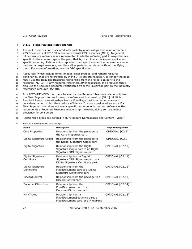
9.1 Fixed Payload Parts and Relationships
22 Working Draft 1.0.1, September 2007
9.1.1 Fixed Payload Relationships 1
Internal resources are associated with parts by relationships and inline references. 2
XPS Documents MUST NOT reference external XPS resources [M2.1]. In general, 3
inline resource references are represented inside the referring part in ways that are 4
specific to the content type of the part, that is, in arbitrary markup or application-5
specific encoding. Relationships represent the type of connection between a source 6
part and a target resource, and they allow parts to be related without modifying 7
them. For more information, see the OPC specification. 8
Resources, which include fonts, images, color profiles, and remote resource 9
dictionaries, that are referenced by inline URIs but are necessary to render the page 10
MUST use the Required Resource relationship from the FixedPage part to the 11
resource [M2.10]. If any resource references other resources, the producer MUST 12
also use the Required Resource relationship from the FixedPage part to the indirectly 13
referenced resource [M2.10]. 14
It is RECOMMENDED that there be exactly one Required Resource relationship from 15
the FixedPage part for each resource referenced from markup [S2.1]. Multiple 16
Required Resource relationships from a FixedPage part to a resource are not 17
considered an error, but they reduce efficiency. It is not considered an error if a 18
FixedPage part that does not use a specific resource in its markup references the 19
resource via a Required Resource relationship; however, doing so may reduce 20
efficiency for consumers. 21
Relationship types are defined in H, ―Standard Namespaces and Content Types.‖ 22
Table 9–2. Fixed payload relationships 23
Name Description Required/Optional
Core Properties Relationship from the package to the Core Properties part.
OPTIONAL [O2.8]
Digital Signature Origin Relationship from the package to
the Digital Signature Origin part.
OPTIONAL [O2.9]
Digital Signature Relationship from the Digital Signature Origin part to an Digital
Signature XML Signature part.
OPTIONAL [O2.10]
Digital Signature Certificate
Relationship from a Digital Signature XML Signature part to a Digital Signature Certificate part.
OPTIONAL [O2.11]
Digital Signature Definitions
Relationship from the FixedDocument part to a Digital Signature Definitions part.
OPTIONAL [O2.12]
DiscardControl Relationship from the package to a DiscardControl part.
OPTIONAL [O2.13]
DocumentStructure Relationship from the FixedDocument part to a DocumentStructure part.
OPTIONAL [O2.14]
PrintTicket Relationship from a
FixedDocumentSequence part, a FixedDocument part, or a FixedPage
OPTIONAL [O2.15]

XPS Specification and Reference Guide 9.1 Fixed Payload
Working Draft 1.0.1, September 2007 23
part to a PrintTicket part.
Required Resource Relationship from a FixedPage part to a required resource, including Font, Image, ColorProfile, and
Remote Resource Dictionary parts. Required resources can be shared between pages.
REQUIRED for each resource referenced from a FixedPage
[M2.10]
Restricted Font Relationship from a FixedDocument part to a Font part. Specifies the referenced font as restricted, disallowing any modification or
editing of any <Glyphs> element text using the referenced font.
REQUIRED for each preview and print font used [M2.12]
StartPart Relationship from the package to the FixedDocumentSequence part
that is the primary fixed payload root.
REQUIRED [M2.13, M2.14]
StoryFragments Relationship from a FixedPage part
to the StoryFragments part for the page.
OPTIONAL [O2.16]
Thumbnail Relationship from the package to an
Image part or from a FixedPage part to an Image part.
OPTIONAL [O2.17]
Producers that generate a relationship MUST include the target part in the XPS 1
Document for any of the following relationship types: DiscardControl, 2
DocumentStructure, PrintTicket, Required Resource, Restricted Font, StartPart, 3
StoryFragments, and Thumbnail. Consumers that access the target part of any 4
relationship with one of these relationship types MUST generate an error if the part is 5
not included in the XPS Document [M2.77]. 6
9.1.2 FixedDocumentSequence Part 7
The FixedDocumentSequence part assembles a set of fixed documents within the 8
fixed payload. [Example: A printing client can assemble two separate documents, a 9
two-page cover memo and a twenty-page report (both are FixedDocument parts), 10
into a single package to send to the printer. end example] 11
The FixedDocumentSequence part is the only valid root of a fixed payload. Even if an 12
XPS Document contains only a single fixed document, the FixedDocumentSequence 13
part is still used. One FixedDocumentSequence part per fixed payload is REQUIRED 14
[M2.3]. 15
Fixed document sequence markup specifies each fixed document in the fixed payload 16
in sequence, using <DocumentReference> elements. The order of 17
<DocumentReference> elements determines document order and MUST be 18
preserved by editing consumers [M2.15]. Each <DocumentReference> element 19
SHOULD reference a FixedDocument part by relative URI [S2.2]. For more 20
information, see §10.1, ―<FixedDocumentSequence> Element,‖ on page 49. 21
The content type of the FixedDocumentSequence part is defined in H, ―Standard 22
Namespaces and Content Types.‖ 23

9.1 Fixed Payload Parts and Relationships
24 Working Draft 1.0.1, September 2007
9.1.3 FixedDocument Part 1
The FixedDocument part is a common, easily indexed root for all pages within the 2
document. A fixed document identifies the set of fixed pages for the document. 3
The markup in the FixedDocument part specifies the pages of a document in 4
sequence using <PageContent> elements. The order of <PageContent> elements 5
determines page order and MUST be preserved by editing consumers [M2.16]. Each 6
<PageContent> element SHOULD reference a FixedPage part by relative URI [S2.3]. 7
For more information, see §10.2, ―<FixedDocument> Element,‖ on page 50. 8
The content type of the FixedDocument part is defined in H, ―Standard Namespaces 9
and Content Types.‖ 10
9.1.4 FixedPage Part 11
The FixedPage part contains all of the visual elements to be rendered on a page. 12
Each page has a fixed size and orientation. The layout of the visual elements on a 13
page is determined by the fixed page markup. This applies to both graphics and text, 14
which are represented with precise typographic placement. The contents of a page 15
are described using a powerful but simple set of visual primitives. 16
Each FixedPage part specifies the contents of a page within a <FixedPage> element 17
using <Path> and <Glyphs> elements (using various brush elements) and the 18
<Canvas> grouping element. The <ImageBrush> and <Glyphs> elements (or their 19
child or descendant elements) can reference Image parts or Font parts by URI. They 20
SHOULD reference these parts by relative URI [S2.4]. For more information, 21
see §10.3, ―<FixedPage> Element,‖ on page 53. 22
The content type of the FixedPage part is defined in H, ―Standard Namespaces and 23
Content Types.‖ 24
9.1.5 Image Parts 25
Image parts reference image files. A single image may be shared among multiple 26
fixed pages in one or more fixed documents. Images referenced in markup MUST be 27
internal to the package [M2.1]. References to images that are external to the 28
package are invalid. 29
Images are included in XPS Documents with an <ImageBrush> element and an 30
ImageSource attribute to reference a part with the appropriate content type. For 31
more information, see §H.2, ―Content Types,‖ on page 406. Fixed pages MUST use a 32
Required Resource relationship to each Image part referenced [M2.10]. For more 33
information, see §H.3, ―Relationship Types,‖ on page 407. 34
XPS Documents support the following image formats: 35
JPEG 36
PNG 37
TIFF 38
Windows Media Photo 39
Color profiles MAY be embedded in image files [O2.18] and SHOULD be used by 40
consumers [S2.5]. See 15, ―Color,‖ for more details. 41
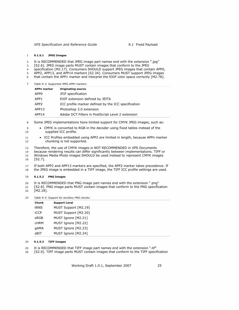
XPS Specification and Reference Guide 9.1 Fixed Payload
Working Draft 1.0.1, September 2007 25
9.1.5.1 JPEG Images 1
It is RECOMMENDED that JPEG image part names end with the extension ―.jpg‖ 2
[S2.6]. JPEG image parts MUST contain images that conform to the JPEG 3
specification [M2.17]. Consumers SHOULD support JPEG images that contain APP0, 4
APP2, APP13, and APP14 markers [S2.34]. Consumers MUST support JPEG images 5
that contain the APP1 marker and interpret the EXIF color space correctly [M2.78]. 6
Table 9–3. Supported JPEG APPn markers 7
APPn marker Originating source
APP0 JFIF specification
APP1 EXIF extension defined by JEITA
APP2 ICC profile marker defined by the ICC specification
APP13 Photoshop 3.0 extension
APP14 Adobe DCT Filters in PostScript Level 2 extension
Some JPEG implementations have limited support for CMYK JPEG images, such as: 8
CMYK is converted to RGB in the decoder using fixed tables instead of the 9
supplied ICC profile. 10
ICC Profiles embedded using APP2 are limited in length, because APPn marker 11
chunking is not supported. 12
Therefore, the use of CMYK images is NOT RECOMMENDED in XPS Documents 13
because rendering results can differ significantly between implementations. TIFF or 14
Windows Media Photo images SHOULD be used instead to represent CMYK images 15
[S2.7]. 16
If both APP2 and APP13 markers are specified, the APP2 marker takes precedence. If 17
the JPEG image is embedded in a TIFF image, the TIFF ICC profile settings are used. 18
9.1.5.2 PNG Images 19
It is RECOMMENDED that PNG image part names end with the extension ―.png‖ 20
[S2.8]. PNG image parts MUST contain images that conform to the PNG specification 21
[M2.18]. 22
Table 9–4. Support for ancillary PNG chunks 23
Chunk Support Level
tRNS MUST Support [M2.19]
iCCP MUST Support [M2.20]
sRGB MUST Ignore [M2.21]
cHRM MUST Ignore [M2.22]
gAMA MUST Ignore [M2.23]
sBIT MUST Ignore [M2.24]
9.1.5.3 TIFF Images 24
It is RECOMMENDED that TIFF image part names end with the extension ―.tif‖ 25
[S2.9]. TIFF image parts MUST contain images that conform to the TIFF specification 26

9.1 Fixed Payload Parts and Relationships
26 Working Draft 1.0.1, September 2007
[M2.25]. XPS Document consumers MUST support baseline TIFF 6.0 with some 1
extensions, as noted in Table 9–5 [M2.26]. These tags MUST be supported for the 2
specified image types [M2.26]. If consumers encounter a tag that is not included 3
below, they SHOULD ignore that tag [S2.10]. 4
Table 9–5. Supported TIFF 6.0 tags 5
Image type Tags
Bilevel images PhotometricInterpretation (0 and 1)
Compression (1, 2, 3, 4, 5, or 32773)
ImageLength
ImageWidth
ResolutionUnit (1, 2, or 3)
RowsPerStrip
StripByteCounts
StripOffsets
XResolution
YResolution
Grayscale images
PhotometricInterpretation (0 and 1)
BitsPerSample (4, 8, or 16)
Compression (1, 5, 6, or 32773)
ImageLength
ImageWidth
ResolutionUnit (1, 2, or 3)
RowsPerStrip
StripByteCounts
StripOffsets
XResolution
YResolution
Palette color
images
BitsPerSample (1, 4, or 8)
ColorMap
Compression (1, 5, or 32773)
ImageLength
ImageWidth
PhotometricInterpretation (3)
ResolutionUnit (1, 2, or 3)
RowsPerStrip
StripByteCounts
StripOffsets
XResolution
YResolution
RGB images BitsPerSample (8,8,8 or 16,16,16; or if ExtraSamples=1 or 2:
8,8,8,8 or 16,16,16,16)
Compression (1, 5, 6, or 32773)

XPS Specification and Reference Guide 9.1 Fixed Payload
Working Draft 1.0.1, September 2007 27
ExtraSamples (0, 1, or 2)
ICC Color Profile [tag 34675]
ImageLength
ImageWidth
PhotometricInterpretation (2)
PlanarConfiguration (1)
ResolutionUnit (1, 2, or 3)
RowsPerStrip
SamplesPerPixel (3; or if ExtraSamples=1 or 2: 4)
StripByteCounts
StripOffsets
XResolution
YResolution
CMYK images (TIFF
extension)
BitsPerSample (8,8,8,8 or 16,16,16,16; or if ExtraSamples=1 or 2: 8,8,8,8,8 or
16,16,16,16,16)
Compression (1, 5, 6, or 32773)
ExtraSamples (0, 1, or 2)
ICC Color Profile [tag 34675]
ImageLength
ImageWidth
InkSet (1)
NumberOfInks (4)
PhotometricInterpretation (5)
PlanarConfiguration (1)
ResolutionUnit (1, 2, or 3)
RowsPerStrip
SamplesPerPixel (4; or if ExtraSamples=1 or 2: 5)
StripByteCounts
StripOffsets
XResolution
YResolution
If the TIFF image contains multiple image file directories (IFDs), consumers MUST 1
use only the first IFD and ignore all others [M2.27]. 2
If the ResolutionUnit tag is set to 1 (no units), XResolution and YResolution are 3
interpreted in the same manner as if the ResolutionUnit was set to 2 (inches). 4
If no color profile is embedded in the TIFF image or stored in a separate part 5
associated with the TIFF image according to the mechanisms described in §15.2.8, 6
―Images and Color Profile Association‖ on page 216, then the default color space 7
MUST be treated as defined in §15.2.9, ―Color Space Pixel Formats for Raster 8
Images,‖ on page 216 [M8.30]. 9

9.1 Fixed Payload Parts and Relationships
28 Working Draft 1.0.1, September 2007
The following features of the TIFF specification MUST be supported in addition to the 1
tags described in Table 9–5: 2
Baseline TIFF (Sections 1–10) with the exception of the following tags 3
[M2.26]: 4
o CellLength 5
o CellWidth 6
o GrayResponseCurve 7
o GrayResponseUnit 8
o MaxSampleValue 9
o MinSampleValue 10
o Orientation 11
o Thresholding 12
CCITT bilevel encodings (Section 11) [M2.28] 13
CMYK images (Section 16) [M2.29] 14

XPS Specification and Reference Guide 9.1 Fixed Payload
Working Draft 1.0.1, September 2007 29
Associated alpha data (Section 18) [M2.30] 1
o ExtraSamples tag value of 1: Treat alpha as pre-multiplied alpha 2
(see §18.4.1, ―Pre-Multiplied Alpha and Superluminous Colors,‖ on page 3
281 for details) 4
o ExtraSamples tag value of 2: Treat alpha as non-pre-multiplied alpha 5
LZW compression (Section 13) [M2.31] 6
Differencing predictors (Section 14) [M2.32] 7
JPEG compression (Section 22) 8
o Only compression mode 6 MUST be supported [M2.33] 9
Embedded ICC Profile (described in the ICC specification) [M2.34] 10
EXIF IFD (tag 34665) as described in the EXIF specification. The EXIF color 11
space MUST be interpreted correctly [M2.79]. 12
Consumers that support tags and features not described above can result in 13
undesirable differences in the appearance of XPS Documents. Producers cannot rely 14
on a consistent interpretation of tags or features that are not described above and 15
therefore SHOULD NOT use any such tags or features [S2.10]. 16
[Note: Many TIFF images in circulation today deviate from the TIFF Specification. 17
Over time, TIFF-consuming implementations have developed a certain tolerance for 18
such deviations by attempting to deduce the intent of the TIFF image author and 19
correct for apparent errors or deviations. end note] 20
Therefore, XPS Document consumers SHOULD do the following [S2.11]: 21
Test with as many different TIFF images as possible. 22
Correct common mistakes in TIFF images, such as: 23
o Not all BitsPerSample hold the same value 24
o Number of BitsPerSample does not match SamplesPerPixel 25
o PhotometricInterpretation 1 or 2 (instead of 3) used when BitsPerSample 26
is set to ―8,8,8‖ 27
o Missing ExtraSamples tag, but SamplesPerPixel does not match the value 28
expected by the PhotometricInterpretation tag, thus necessitating 29
deduction of the ExtraSamples value. 30
Implement a reasonable recovery strategy when a problematic TIFF image is 31
encountered. 32
9.1.5.4 Windows Media Photo Images 33
It is RECOMMENDED that Windows Media Photo image part names end with the 34
extension ―.wdp‖ [S2.12]. Windows Media Photo image files MUST conform to the 35
Windows Media Photo specification [M2.35]. XPS Documents support Windows Media 36
Photo images with the characteristics identified in Table 9–6. 37
Comment [rcj3]: What is "reasonable"?

9.1 Fixed Payload Parts and Relationships
30 Working Draft 1.0.1, September 2007
Table 9–6. Supported Windows Media Photo features 1
Color space Pixel formats Compression Alpha
Grayscale 8-bit integer
16-bit integer
16-bit half-float*
16-bit fixed point*
32-bit fixed point*
Lossy
Lossless
None
sRGB 8-bit integer
16-bit integer
Lossy
Lossless
1-channel
1-channel pre-multiplied
scRGB 16-bit half-float
16-bit fixed point
32-bit IEEE float
32-bit fixed
point
RGBE-Radiance
Lossy
Lossless
1-channel
1-channel pre-multiplied
RGBE-Radiance (no alpha
channel)
CMYK 8-bit integer
16-bit integer
Lossy
Lossless
1-channel independent
N-channel (including named color N-tone)
8-bit integer
16-bit integer
Lossy
Lossless
1-channel independent
Profiled RGB (3-channel)
8-bit integer
16-bit integer
Lossy
Lossless
1-channel
1-channel pre-multiplied
* The value range of these formats is the same as scRGB. 2
If no color profile is embedded in the Windows Media Photo image or stored in a 3
separate part associated with the Windows Media Photo image according to the 4
mechanisms described in §15.2.8, ―Images and Color Profile Association‖ on page 5
216, then the default color space MUST be treated as defined in §15.2.9, ―Color 6
Space Pixel Formats for Raster Images,‖ on page 216 [M8.30]. 7
9.1.6 Thumbnail Parts 8
Thumbnails are small images that represent the contents of a fixed page or an entire 9
XPS Document. Thumbnails enable users of viewing applications to select a page 10
easily. 11
Thumbnail images MAY be attached using a relationship to the FixedPage parts 12
[O2.19]. Each FixedPage part MUST NOT have more than one thumbnail part 13
attached [M2.36]. Relationships to thumbnail parts are defined in H, ―Standard 14
Namespaces and Content Types.‖ It is RECOMMENDED that if thumbnails are used 15
for pages, a thumbnail SHOULD be included for every page in the document [S2.13]. 16
Although the OPC specification allows thumbnails to be attached to any part, XPS 17
Document consumers SHOULD only process thumbnails associated via a package 18
Comment [rcj4]: Does this mean a different thumbnail for each page?
Clarify.

XPS Specification and Reference Guide 9.1 Fixed Payload
Working Draft 1.0.1, September 2007 31
relationship from the package as a whole or via a relationship from a FixedPage part 1
[S2.14]. These thumbnails MUST be in either JPEG or PNG format [M2.37]. 2
Thumbnails attached to any other part SHOULD be ignored by XPS Document 3
consumers [S2.14]. The content types of thumbnail parts are specified in §H.2, 4
―Content Types,‖ on page 406. 5
For more information about the relationship type for thumbnail parts, see §H.3, 6
―Relationship Types,‖ on page 407. 7
9.1.7 Font Parts 8
Fonts are stored in font parts. XPS Documents MUST support the OpenType font 9
format, which includes TrueType and CFF fonts [M2.39]. To support portability, 10
Unicode-encoded fonts SHOULD be used (see §9.1.7.5, ―Non-Standard Font 11
Compatibility Encoding‖ for additional information) [S2.15]. 12
Font parts are referenced using the FontUri attribute of the <Glyphs> element. A 13
single font may be shared among multiple fixed pages in one or more fixed 14
documents. Font references MUST be internal to the package; external references to 15
fonts are invalid [M2.1]. 16
If the referenced font part is a TrueType Collection, the fragment portion of the URI 17
indicates the font face to be used. The use of URI fragments is specified in the BNF 18
of Generic URI Syntax specification. The fragment contained in the FontURI 19
attribute value MUST be an integer between 0 and n−1 inclusive, where n is the 20
number of font faces contained in the TrueType Collection [M2.38]. [Example: To 21
reference the first font face in the font part ―../Resources/Fonts/CJKSuper.ttc‖, the 22
value of the FontUri attribute is ―../Resources/Fonts/CJKSuper.ttc#0‖. end 23
example] If no fragment is specified, the first font face is used in the same way as if 24
the URI had specified ―#0‖. 25
Content types for fonts differ depending on whether the font is non-obfuscated or 26
obfuscated (see §9.1.7.2, ―OpenType Font Embedding,‖ on page 31). Content types 27
are summarized in H, ―Standard Namespaces and Content Types.‖ 28
Fixed pages MUST use a Required Resource relationship to each Font parts 29
referenced [M2.10]. For more information, see H. 30
9.1.7.1 Subsetting Fonts 31
XPS Documents represent text using the <Glyphs> element. Since the format is 32
fixed, it is possible to create a font subset that contains only the glyphs required by 33
the package. Fonts MAY be subsetted based on glyph usage [O2.20]. Although a 34
subsetted font does not contain all the glyphs in the original font, it MUST be a valid 35
OpenType font file [M2.39]. Requirements for valid OpenType font files are described 36
in the OpenType Font File specification. 37
9.1.7.2 OpenType Font Embedding 38
Protecting the intellectual property of font vendors is a goal of the XPS Document 39
format. Therefore, producers MUST observe the guidelines and mechanisms 40
described below in order to honor the licensing rights specified in OpenType fonts 41
[M2.40]. It is not the responsibility of consumers to enforce font licensing intent, 42
although consumers MUST be able to process XPS Documents using any combination 43

9.1 Fixed Payload Parts and Relationships
32 Working Draft 1.0.1, September 2007
of these embedding and obfuscation mechanisms, even if produced in violation of 1
these guidelines [M2.41]. 2
The licensing rights of an OpenType font are specified in the fsType field of the 3
required OS/2 table in the font file. Table 9–7 lists the bit mask values that can 4
appear in arbitrary combinations in the fsType field. Also listed are short descriptions 5
of the licensing right intents and requirements or recommendations. These 6
requirements represent the ―rules‖ that producers and consumers must follow in 7
order to respect licensing rights specified in the font. 8
For further details on licensing rights of OpenType fonts, see the description of the 9
OS/2 table in ―OS/2 and Windows Metrics.‖ 10
Table 9–7. Guidelines for OpenType font embedding 11
Bit/mask Licensing right
intent
Producer rules Consumer rules
− / 0x0000
Installable embedding.
SHOULD do embedded font obfuscation [S2.16]
(see §9.1.7.3, ―Embedded Font
Obfuscation,‖ on page 33 for details).
SHOULD NOT extract or install permanently
(see below) [S2.17].
0 /
0x0001
Reserved, must be
0.
1 / 0x0002
Restricted license embedding. If only this bit is set, the font MUST NOT be
modified, embedded or exchanged in any manner without obtaining permission from the legal owner.
MUST NOT embed [M2.42].
SHOULD generate a path filled
with an image brush referencing an image of
rendered characters [S2.18].
SHOULD include the text in the AutomationProperties.Name
attribute of the <Path> element [S2.18].
Render embedded images.
2 / 0x0004
For preview and print embedding,
font may be embedded and temporarily used on remote
systems. However, documents containing any preview and print fonts MUST NOT
be modified or edited [M2.43].
MUST do embedded font obfuscation [M2.44]
(see §9.1.7.3).
MUST add a Restricted Font relationship to the FixedDocument part of the document containing the font [M2.12]. See §12.1.7, ―DeviceFontName Attribute,‖ on page 115 and §H.3, ―Relationship Types,‖ on page 407 for details.
MUST NOT extract or install permanently
[M2.45].
MUST NOT modify or edit the XPS Document markup or hierarchical structure starting from the <FixedDocument> element [M2.43].
3 / 0x0008
Editable embedding.
MUST do embedded font obfuscation [M2.46] (see §9.1.7.3).
MUST NOT extract or install permanently [M2.47].
4–7 Reserved, must be

XPS Specification and Reference Guide 9.1 Fixed Payload
Working Draft 1.0.1, September 2007 33
0.
8 / 0x0100
No subsetting. MUST do embedded font obfuscation (see §9.1.7.3) [M2.48].
MUST NOT subset font before embedding.
MUST NOT extract or install permanently [M2.50].
9 /
0x0200
Bitmap embedding
only.
MUST do embedded font
obfuscation [M2.51] (see §9.1.7.3).
MUST embed only bitmap characters contained in the font [M2.51].
If no bitmap characters are
present in the font, MUST NOT
embed the font [M2.51].
MUST NOT extract or
install permanently [M2.52].
10–15 Reserved, must be 0.
9.1.7.3 Embedded Font Obfuscation 1
Embedded font obfuscation is a means of preventing casual misappropriation of 2
embedded fonts. Specifically, embedded font obfuscation prevents end-users from 3
using standard ZIP utilities to extract fonts from XPS Document files and install them 4
on their systems. 5
Embedded font obfuscation is not considered a strong encryption of the font data. 6
Embedded font obfuscation achieves the following goals: 7
4. Obfuscated font files are embedded within an XPS Document package in a 8
form that cannot be directly installed on any client operating system. 9
5. Obfuscated font files are closely tied to the content referencing them. 10
Therefore, it is non-trivial to misappropriate fonts by moving them from one 11
package to another. 12
6. The manner in which obfuscated font files are tied to the content referencing 13
them still allows for document merging.0. 14
For information on how to determine when fonts must be obfuscated prior to 15
embedding, see Table 9–7. above. 16
Although the licensing intent allows embedding of non-obfuscated fonts and 17
installation of the font on a remote client system under certain conditions, this is 18
NOT RECOMMENDED in XPS Documents. [Note: Microsoft implementations for XPS 19
Documents always perform obfuscated font embedding and do not extract or 20
permanently install the font [S2.19]. end note] However, there are vertical solutions 21
in which implementations may benefit from un-obfuscated font embedding. In these 22
cases, implementations could omit obfuscation or extract and install the embedded 23
font. 24
9.1 Fixed Payload Parts and Relationships
34 Working Draft 1.0.1, September 2007
If a producer is required to perform embedded font obfuscation, it MUST satisfy the 1
following requirements [M2.53]: 2
1. Generate a 128-bit GUID (Globally Unique Identifier) for the font to be 3
obfuscated. Instead of a true GUID, a 128-bit random number MAY be used 4
[O2.21]. The 16 bytes of the 128-bit GUID are referred to in the following text 5
by the placeholder names B00, B01, B02, B03; B10, B11; B20, B21; B30, B31, B32, 6
B33, B34, B35, B36, and B37. The order in which bytes are assigned to these 7
placeholders does not matter, as long as it is consistent for obfuscation and 8
de-obfuscation. 9
2. Generate a part name for the obfuscated font using the GUID. The last 10
segment of the part name MUST be of the form ―B03B02B01B00-B11B10-B21B20-11
B30B31-B32B33B34B35B36B37‖ or ―B03B02B01B00-B11B10-B21B20-B30B31-12
B32B33B34B35B36B37.ext‖ where each Bx represents a placeholder for one byte of 13
the GUID, represented as two hex digits [M2.54]. The part name MAY have an 14
arbitrary extension (identified by the placeholder ―.ext‖) [O2.22]. It is 15
RECOMMENDED that the extension for TrueType fonts be ―.odttf‖ and for 16
TrueType collections be ―.odttc‖ [S2.20]. 17
3. The content type for the part containing the obfuscated font MUST match the 18
definition in H, ―Standard Namespaces and Content Types‖ [M2.2]. 19
4. Perform an XOR operation on the first 32 bytes of the binary data of the font 20
part with the array consisting of the bytes referred to by the placeholders B37, 21
B36, B35, B34, B33, B32, B31, B30, B20, B21, B10, B11, B00, B01, B02, and B03, in that 22
order and repeating the array once. The result is an obfuscated font. 23
5. Store the obfuscated font in a part with the generated name.0. 24
When processing fonts, consumers MUST follow these steps [M2.53]: 25
1. If the content type of the part containing the font is not the obfuscated font 26
content type as specified in H, process the font without any de-obfuscation 27
steps. 28
2. For font parts with the obfuscated font content type as specified in H, de-29
obfuscate the font by following these rules:2. 30
a. Remove the extension from the last segment of the name of the part 31
containing the font. 32
b. Convert the remaining characters of the last segment to a GUID using the 33
byte ordering described above. 34
c. Perform an XOR operation on the first 32 bytes of the binary data of the 35
obfuscated font part with the array consisting of the bytes referred to by 36
the placeholders B37, B36, B35, B34, B33, B32, B31, B30, B20, B21, B10, B11, B00, 37
B01, B02, and B03, in that order and repeating the array once. The result is a 38
non-obfuscated font. 39
d. Use the non-obfuscated font for the duration of the document processing, 40
but do not leave any local or otherwise user-accessible copy of the non-41
obfuscated font. . 42

XPS Specification and Reference Guide 9.1 Fixed Payload
Working Draft 1.0.1, September 2007 35
9.1.7.4 Print and Preview Restricted Fonts 1
If a producer embeds a font with the print and preview restriction bit set, it MUST 2
also add a Restricted Font relationship from the FixedDocument part that includes 3
the FixedPage referencing the font to the restricted font [M2.12]. 4
Editing consumers MUST NOT edit a document where the FixedDocument part has a 5
Restricted Font relationship [M2.43]. When invoking editing functionality, editing 6
consumers MUST treat as an error any font with the print and preview restriction bit 7
set for which no Restricted Font relationship has been added to the FixedDocument 8
part [M2.12]. 9
Printing and display-only consumers MUST consider an XPS Document valid even if 10
the producer failed to properly set the Restricted Font relationship [M2.12]. 11
9.1.7.5 Non-Standard Font Compatibility Encoding 12
When processing <Glyphs> elements, the consumer MUST first select a cmap table 13
from the OpenType font following the order of preference shown below (highest 14
listed first) [M2.55]: 15
Table 9–8. Cmap table selection 16
Platform ID Encoding ID Description
3 10 Unicode with surrogates
3 1 Unicode without surrogates
3 5 Wansung
3 4 Big5
3 3 Prc
3 2 ShiftJis
3 0 Symbol
0 Any Unicode (deprecated)
1 0 MacRoman
All further processing for that font MUST use the selected cmap table [M2.55]. 17
If a Wansung, Big5, Prc, ShiftJis or MacRoman cmap has been selected, the 18
consumer MUST correctly map from Unicode codepoints in the UnicodeString to the 19
corresponding codepoints used by the cmap before looking up the glyphs [M2.56]. 20
The Unicode standard provides details of the required mappings. 21
Producers SHOULD avoid using fonts lacking a Unicode-encoded cmap table [S2.15]. 22
When processing <Glyphs> elements that reference a cmap (3,0) encoding font, 23
consumers MUST be prepared for the case in which the UnicodeString attribute 24
contains character codes instead of PUA codepoints [M2.57]. This condition is 25
indicated by an unsuccessful Unicode lookup of the codepoint specified in the 26
Unicode string in the cmap (3,0) table. In this case, the correct glyph index is 27
computed by following the general recommendations of the OpenType specification. 28
When processing <Glyphs> elements that use this compatibility encoding, character 29
codes in the range 0x20-0xff are mapped to PUA codepoints. Therefore, character 30
Comment [rcj5]: Are these subcategories of consumer that need defining?

9.1 Fixed Payload Parts and Relationships
36 Working Draft 1.0.1, September 2007
codes in the range 0x80-0x9f are not considered non-printable Unicode control 1
codes. 2
This non-standard encoding has been included to facilitate document production for 3
certain producers. However, there are significant drawbacks resulting from this 4
encoding: 5
Search is unpredictable 6
Copy and paste functionality is unpredictable 7
Producers are discouraged from using this non-standard encoding and they SHOULD 8
write PUA codepoints to the UnicodeString attribute [S2.15]. 9
9.1.8 Remote Resource Dictionary Parts 10
A remote resource dictionary allows producers to define resources that can be 11
reused across many pages, such as a brush. This is stored in a Remote Resource 12
Dictionary part. For more information, see §14.2.3.1, ―Remote Resource 13
Dictionaries,‖ on page 177. 14
9.1.9 PrintTicket Parts 15
PrintTicket parts provide user intent and device configuration information to printing 16
consumers. PrintTicket parts MUST be processed when the XPS Document is printed 17
[M2.58]. PrintTicket parts can be attached only to FixedDocumentSequence, 18
FixedDocument and FixedPage parts and each of these parts MUST attach no more 19
than one PrintTicket [M2.59]. PrintTickets can provide override settings to be used 20
when printing the part to which they are attached. 21
9.1.9.1 PrintTicket Format 22
The PrintTicket is XML that provides print settings in a consistent, accessible, and 23
extensible manner. Valid PrintTicket settings are specified in the Print Schema. 24
Within the context of an XPS Document, the PrintTicket is generated by the 25
producer. Producers should note that an XPS Document may be printed on various 26
devices, and that the settings included in the PrintTicket SHOULD support portability 27
[S2.21]. Producers and consumers should note that not all PrintTicket keywords 28
defined in the Print Schema are applicable to XPS Documents. 29
9.1.9.2 Mapping PrintTicket Parts to Fixed Payload Parts 30
The PrintTicket defines a hierarchy of print settings to identify the applicability of a 31
setting to different content levels within a print job. Specifically, the PrintTicket 32
supports a hierarchy that is rooted in the print job. Multiple documents are derived 33
from the print job, and multiple pages are defined from each document. A PrintTicket 34
can be associated with each level in this hierarchy. These PrintTicket parts are 35
labeled ―job-level,‖ ―document-level,‖ and ―page-level,‖ respectively. 36
Print settings are defined within the PrintTicket. Each print setting has a scoping 37
prefix to indicate the level at which it applies. [Example: ―JobInputBin‖ is a job-level 38
setting, ―DocumentStaple‖ is a document-level setting, and ―PageOrientation‖ is a 39
page-level setting. end example] Settings in level-specific PrintTicket parts are 40
restricted by the scoping prefix. A level-specific PrintTicket MUST contain only 41
settings scoped to the current level and child levels [M2.59]. Job-level PrintTicket 42
parts MUST contain only job-, document-, and page-scoped settings; document-level 43
Comment [rcj6]: Should this be wriiten using SHOULD NOT?

XPS Specification and Reference Guide 9.1 Fixed Payload
Working Draft 1.0.1, September 2007 37
PrintTicket parts MUST contain only document-scoped and page-scoped settings; and 1
page-level PrintTicket parts MUST contain only page-scoped settings [M2.59]. 2
Within an XPS Document, there is a direct mapping between the PrintTicket levels 3
and the fixed payload parts: 4
Consumers MUST process job-level, document-level and page-level settings of 5
PrintTicket parts associated with FixedDocumentSequence parts [M2.60]. 6
Producers SHOULD only attach PrintTicket parts containing only document-7
level and page-level settings with FixedDocument parts [S2.22]. 8
Consumers MUST process document-level and page-level settings of 9
PrintTicket parts associated with FixedDocument parts and MUST ignore job-10
level settings of PrintTicket parts associated with FixedDocument parts 11
[M2.61]. 12
Producers SHOULD only attach PrintTicket parts containing only page-level 13
settings with FixedPage parts [S2.23]. 14
Consumers MUST process page-level settings of PrintTicket parts associated 15
with FixedPage parts and MUST ignore job-level and document-level settings 16
of PrintTicket parts associated with FixedPage parts [M2.62]. 17
PrintTicket parts are associated with parts via the PrintTicket relationship defined in 18
H, ―Standard Namespaces and Content Types.‖ 19
9.1.9.3 Processing PrintTicket Parts 20
Printing consumers MUST process all PrintTicket parts within the XPS Document 21
[M2.58]. 22
When processing a PrintTicket, consumers MUST first remove all levels of PrintTicket 23
content not applicable to the current element [M2.63] (see §9.1.9.2, ―Mapping 24
PrintTicket Parts to Fixed Payload Parts,‖ on page 36). 25
Second, consumers MUST validate the PrintTicket according to the methods defined 26
in the PrintTicket Validation Checklist of the Print Schema documentation [M2.64]. 27
Following validation, the printing consumer MUST properly interpret the print settings 28
according to the following rules for merging two PrintTicket parts [M2.65]. 29
Print settings are expressed by scoped Print Schema elements. Elements may 30
interact between different levels in the PrintTicket hierarchy. Elements that interact 31
between levels MUST be specified at the root of each level ticket [M2.59]. A keyword 32
merge conflict between PrintTicket settings is defined as the same root-level Print 33
Schema element denoted by the same name attribute value appearing in multiple 34
level tickets. There are two options for interactions: 35
1.3. If there is no merge conflict, a prefix-scoped element MUST be pushed 36
or inherited, from a more general ticket to a more specific ticket [M2.66]. This 37
case is isomorphic to the case where both tickets contain an identical element. 38
2.4. If there is a merge conflict, the setting from the most specific ticket 39
precedence [M2.67]. That is, a page-scoped setting in a page-level PrintTicket 40
overwrites an identical page-scoped setting in a document-level or job-level 41
PrintTicket. Likewise, a document-scoped setting in a document-level 42
PrintTicket overwrites an identical document-scoped setting in a job-level 43
PrintTicket.0. 44

9.1 Fixed Payload Parts and Relationships
38 Working Draft 1.0.1, September 2007
To determine the print settings in the XPS Document the following algorithm should 1
be applied: 2
1. Validate the job-level PrintTicket associated with the fixed document sequence 3
by merging and validating the PrintTicket with the default PrintTicket for the 4
print consumer. The default PrintTicket represents the default configuration of 5
the print consumer‘s state; in the case of a print consumer, the state is the 6
current device and print driver configuration. Call the resulting ticket the 7
―validated job-level PrintTicket.‖ If no job-level PrintTicket is supplied, use the 8
default PrintTicket. 9
2. For each FixedDocumentX referenced by the fixed document sequence, 10
perform the following steps: 11
a. Merge and validate the document-level PrintTicket associated with 12
FixedDocumentX with the validated job-level PrintTicket from Step 1. 13
b. Call the resulting ticket the ―validated DocumentX-level PrintTicket.‖ If no 14
document-level PrintTicket is supplied for the current fixed document, the 15
validated job-level PrintTicket from Step 1 should be used. . 16
3. For each FixedPageY referenced by each FixedDocumentX in the fixed 17
document sequence, perform the following steps: 0. 18
a. Merge and validate the page-level PrintTicket associated with FixedPageY 19
with the validated DocumentX-level PrintTicket from Step 2. 20
b. Call the resulting ticket the ―validated PageXY-level PrintTicket.‖ If no page-21
level PrintTicket is supplied for the current fixed page, the validated 22
DocumentX-level PrintTicket from Step 2 should be used. . 23
9.1.10 SignatureDefinitions Part 24
Producers MAY add digital signature requests and instructions to an XPS Document in 25
the form of signature definitions [O2.23]. A producer MAY sign against an existing 26
signature definition to provide additional signature information [O2.24]. A recipient 27
of the document MAY also sign the XPS Document against a signature definition 28
[O2.25]. (This is referred to as ―co-signing.‖) 29
Digital signature definitions are stored in a SignatureDefinitions part. A 30
FixedDocument part refers to a SignatureDefinitions part using a relationship of the 31
SignatureDefinitions type. For more information, see H, ―Standard Namespaces and 32
Content Types.‖ 33
The SignatureDefinitions part is OPTIONAL [O2.6]. Signature definitions MUST 34
conform to the Signature Definitions schema as defined in A [M2.72]. 35
For more information on digital signature support in XPS Documents, see 17, ―XPS 36
Document Package Features.‖ 37
9.1.11 DocumentStructure Part 38
Explicitly authored document structure information is stored in the 39
DocumentStructure part. This part contains the document outline and defines the 40
framework for every element in fixed pages in terms of semantic blocks called 41
stories. Stories are split into StoryFragments parts, which contain content structure 42
markup that defines semantic blocks such as paragraphs and tables. For more 43
information, see 16, ―Document Structure and Interactivity.‖ 44

XPS Specification and Reference Guide 9.1 Fixed Payload
Working Draft 1.0.1, September 2007 39
Document structure markup contains a root <DocumentStructure> element. See 16, 1
―Document Structure and Interactivity,‖ for markup details. The 2
<DocumentStructure> element uses the Document Structure namespace specified 3
in §H.1, ―XML Namespace URIs,‖ on page 405. 4
The DocumentStructure part is referenced by relationship from the FixedDocument 5
part, with the relationship type as specified in H, ―Standard Namespaces and Content 6
Types.‖ The content type of the DocumentStructure part is also specified in H. 7
Consumers MAY provide an algorithmic construction of the structure of an XPS 8
Document based on a page-layout analysis [O2.27], but they MUST NOT use such a 9
method to derive structure for any part of the XPS Document included in the 10
DocumentStructure part [M2.68]. A consumer capable of calculating reading order 11
from the layout of the document MUST use the reading order specified in the 12
DocumentStructure part, even though the derived order may be perceived as 13
preferable to the specified order [M2.68]. 14
9.1.12 StoryFragments Part 15
The StoryFragments part contains content structure markup (such as tables and 16
paragraphs) associated with a single fixed page. 17
StoryFragments part markup contains a root <StoryFragments> element. See 16, 18
―Document Structure and Interactivity,‖ for markup details. The <StoryFragments> 19
element uses the Document Structure namespace specified in §H.1, ―XML 20
Namespace URIs,‖ on page 405. 21
The StoryFragments part is referenced by relationship from its associated FixedPage 22
part. The content type of the StoryFragments part is specified in §H.2, ―Content 23
Types,‖ on page 406. 24

9.2 Part Naming Recommendations Parts and Relationships
40 Working Draft 1.0.1, September 2007
9.2 Part Naming Recommendations 1
Producers and consumers of XPS Documents refer to parts by name and use 2
relationship names to identify the purpose of related parts. The OPC specification 3
describes the syntax for part names. However, following these rules alone can result 4
in a package that is difficult for users to understand. [Example: A user would have to 5
open every Relationship part to know which parts are necessary to accurately render 6
an XPS Document. end example] 7
By choosing part names according to a well-defined, human-readable convention, 8
the resulting package is easier to browse and specific parts are more easily located. 9
Part names MUST still conform to the syntax specified in the OPC specification 10
[M1.1]. 11
It is RECOMMENDED that producers of XPS Documents use the following part naming 12
convention: 13
The FixedDocumentSequence part name SHOULD contain only one segment 14
with the extension ―.fdseq‖. [Example: ―/FixedDocSeq.fdseq‖ end example] 15
[S2.24]. 16
A FixedDocument part name SHOULD contain three segments, using 17
―/Documents/n/‖ in the first two segments and the extension ―.fdoc‖ [S2.25]. 18
Here, n SHOULD be a numeral that represents the ordinal position of the fixed 19
document in the fixed document sequence [S2.25]. [Example: The fixed 20
document referenced by the Source attribute of the third 21
<DocumentReference> child of the <FixedDocumentSequence> element 22
could be ―/Documents/3/FixedDocument.fdoc‖. end example] 23
A FixedPage part name SHOULD contain four segments, using 24
―/Documents/n/Pages/‖ as the first three segments and the extension 25
―.fpage‖ on the last segment [S2.26]. Here, n represents the fixed document 26
that includes this page. [Example: The third page of the second document 27
might be ―/Documents/2/Pages/3.fpage‖. end example] 28
Resource parts MAY be named to indicate whether their intended use is at the 29
document level or as a shared resource for all documents [O2.28]. A resource 30
that is specific to a particular document SHOULD have a part name that 31
begins with the three segments ―/Documents/n/Resources/‖ where n is the 32
particular fixed document [S2.27]. A resource intended to be shared across 33
documents SHOULD begin with the segment ―/Resources/‖ and SHOULD have 34
a final segment that is a globally unique identifier followed by the appropriate 35
extension for that resource [S2.27]. [Example: ―/Resources/63B51F81-C868-36
11D0-999C-00C04FD655E1.odttf‖ end example] 37
A Font part name SHOULD append the segment ―Fonts/‖ to the resource part 38
name prefix specified above [S2.27]. [Example: A font might be named 39
―/Documents/1/Resources/Fonts/Arial.ttf‖ or ―/Resources/F2ABC7B7-C60D-40
4FB9-AAE4-3CA0F6C7038A.odttf‖. end example] 41
An Image part name SHOULD append the segment ―Images/‖ to the resource 42
part name specified above [S2.27]. [Example: An image might be named 43
―/Documents/3/Resources/Images/dog.jpg‖ or 44
―/Resources/Images/E0D79307-846E-11CE-9641-444553540000.jpg‖. end 45
example] 46
Comment [rcj7]: Is a comma missing
here? That is, should there be only 1 segmant, and that segment's has an extension of .fdseq? Or can there me mor ethan 1 segment, but only 1 with that extension?
XPS Specification and Reference Guide 9.2 Part Naming Recommendations
Working Draft 1.0.1, September 2007 41
A Remote Resource Dictionary part name SHOULD append the segment 1
―Dictionaries/‖ to the resource part name specified above [S2.27]. Remote 2
resource dictionaries SHOULD also use the ―.dict‖ extension [S2.27]. 3
[Example: A resource dictionary might be named 4
―/Documents/2/Resources/Dictionaries/Shapes.dict‖ or 5
―/Resources/0DDF3BE2-E692-15D1-AB06-B0AA00BDD685.dict‖. end 6
example] 7
Any DocumentStructure part name SHOULD contain four segments using 8
―/Documents/n/Structure/‖ as the first three segments and the extension 9
―.struct‖ [S2.28]. Here n represents the fixed document that this structure is 10
associated with. [Example: The DocumentStructure part for the first 11
document in a fixed document sequence could be 12
―/Documents/1/Structure/DocStructure.struct‖. end example] 13
Any StoryFragments part name SHOULD contain five segments using 14
―/Documents/n/Structure/Fragments‖ as the first four segments and the 15
extension ―.frag‖ [S2.29]. Here n represents the fixed document that these 16
parts are associated with. [Example: A StoryFragment part associated with 17
the third page of the second document in a fixed document sequence could be 18
―/Documents/2/Structure/Fragments/3.frag‖. end example] 19
ICC profile part names SHOULD contain four segments, using 20
―/Documents/n/Metadata/‖ as the first three segments, where n is the fixed 21
document that uses these parts [S2.30]. If an ICC profile part is shared 22
across documents, the part name SHOULD contain two segments, using 23
―/Metadata/‖ as the first segment and a second segment that is a string 24
representation of a globally unique identifier, followed by an extension 25
[S2.30]. ICC profiles SHOULD use an appropriate extension for the color 26
profile type. [S2.30] [Example: ―.icm‖ end example] 27
Thumbnail part names SHOULD contain four segments, using 28
―/Documents/n/Metadata/‖ as the first three segments, where n is the fixed 29
document that uses the thumbnail [S2.31]. If the Thumbnail part relates to 30
the package as a whole, the part name SHOULD contain two segments, using 31
―/Metadata/‖ as the first segment and a second segment that is a string 32
representation of a globally unique identifier, followed by an extension 33
[S2.31]. Thumbnails SHOULD use an extension appropriate to the image 34
type, either ―.png‖ or ―.jpg‖ [S2.31]. [Example: A Thumbnail part for a 35
particular fixed page might be ―/Documents/1/Metadata/5.png‖. end 36
example] 37
PrintTicket part names associated with the entire job SHOULD be associated 38
via relationship with the FixedDocumentSequence part and contain two 39
segments, using ―/Metadata/‖ as the first segment [S2.32]. PrintTicket parts 40
associated with a particular fixed document or fixed page SHOULD contain 41
four segments, using ―/Documents/n/Metadata/‖ as the first three segments, 42
where n is the fixed document that uses these parts [S2.32]. PrintTicket parts 43
SHOULD use the extension ―.xml‖ [S2.32]. [Example: A PrintTicket associated 44
with the entire job could be ―/Metadata/Job_PT.xml‖ and a PrintTicket 45
associated with a single page might be 46
―/Documents/1/Metadata/Page2_PT.xml‖. end example] 47
The names of any non-standard parts that are associated with a particular 48
fixed document SHOULD contain four segments, using ―/Documents/n/Other/‖ 49

9.3 XPS Document Markup Parts and Relationships
42 Working Draft 1.0.1, September 2007
as the first three segments. Here, n is the fixed document to which the part 1
belongs [S2.33]. 2
Example 9–2. XPS Document part naming 3
An XPS Document that contains two FixedDocument parts is represented as follows: 4
/FixedDocSeq.fdseq 5
/Documents/1/FixedDocument.fdoc 6
/Documents/1/Pages/1.fpage 7
/Documents/1/Pages/2.fpage 8
/Documents/1/Resources/Fonts/FontA.ttf 9
/Documents/1/Resources/Images/ImageB.jpg 10
/Documents/1/Metadata/Document_PT.xml 11
/Documents/1/Metadata/Page5_PT.xml 12
/Documents/1/Structure/DocStructure.struct 13
/Documents/1/Structure/Fragments/1.frag 14
/Documents/1/Structure/Fragments/2.frag 15
/Documents/1/Other/FabrikamIncBussinessAccount.xml 16
/Documents/2/FixedDocument.fdoc 17
/Documents/2/Pages/1.fpage 18
/Documents/2/Resources/Fonts/FontB.ttf 19
/Documents/2/Resources/Images/ImageA.png 20
/Documents/2/Metadata/ColorProfile.icm 21
/Documents/2/Metadata/Document_PT.xml 22
/Documents/2/Other/FabrikamIncInsuranceInfo.xml 23
/Metadata/Job_PT.xml 24
/Resources/63B51F81-C868-11D0-999C-00C04FD655E1.ttf 25
end example] 26
9.3 XPS Document Markup 27
XPS Document markup has been designed to facilitate the independent development 28
of compatible systems that produce or consume XPS Documents. It also shares 29
concepts with portions of the Microsoft .NET Framework 3.0 programming platform. 30
The graphics rendering model is shared with that of the Windows Presentation 31
Foundation, assuring fidelity between on-screen display and printed output. The 32
syntax of fixed page, fixed document, and fixed document sequence markup is 33
compatible with that of Windows Presentation Foundation XAML. The elements, 34
attributes, and attribute values are a subset of those defined by the Windows 35
Presentation Foundation. 36
The relationship between XPS Document markup and .NET 3.0 technologies does not 37
impose any requirement on system implementations. Support for XPS Document 38
markup does not require incorporation of .NET 3.0, the Windows Presentation 39
Foundation, or managed code. However, the relationship with .NET 3.0 technologies 40
allows producers to extend XPS Document markup for further use in the Windows 41
Presentation Foundation framework, such as by including additional presentation 42
features. 43
The design of XPS Document markup reflects the tradeoffs between two, sometimes 44
competing, goals: 45
1. XPS Document markup should be parsimonious; that is, it should include only 46
the minimum set of primitive operations and markup constructs necessary to 47
render text and graphics with full fidelity. Redundancy in the specification 48

XPS Specification and Reference Guide 9.3 XPS Document Markup
Working Draft 1.0.1, September 2007 43
increases the opportunity for independent implementations, such as printer-1
resident raster image processors (RIPs), viewers, and interactive applications, 2
to introduce accidental incompatibilities. Redundancy also increases the cost of 3
implementation and testing, and, typically, the required memory footprint. 4
2. XPS Document markup should be compact; that is, the most common 5
graphical primitives for vector graphics and text-rendering should have 6
compact representations. Bloated representations compromise the 7
performance of systems handling XPS Documents. As byte-count increases, so 8
does communication time. Although compression can be used to improve 9
communication time, it cannot eliminate the performance loss caused by 10
bloated representations. 0. 11
9.3.1 Support for Versioning and Extensibility 12
XPS Document markup has been designed in anticipation of the evolution of this 13
specification. It also allows third parties to extend the markup. XPS Document 14
markup incorporates the Markup Compatibility specification incorporated by the OPC 15
specification. 16
The following parts MAY include elements and attributes defined in the Markup 17
Compatibility specification [O2.29]: 18
DocumentStructure 19
FixedDocument 20
FixedDocumentSequence 21
FixedPage 22
Relationships 23
Remote Resource Dictionary 24
SignatureDefinitions 25
StoryFragments 26
Consumers of these parts MUST support the Markup Compatibility specification 27
[M2.69]. Before attempting to validate one of these parts against a schema, 28
processors MUST remove all markup compatibility elements and attributes and all 29
ignorable elements and attributes not defined in the expected version of XPS 30
Document markup [M2.69]. 31
[Note: Markup compatibility elements and attributes that appear in one XPS 32
Document part do not carry through to a second part via an inline URI reference in 33
the XML markup. Likewise the markup compatibility mechanisms do not carry 34
through from part to part via relationship. end note] 35
9.3.2 XML Usage 36
All XML content of the parts defined in this specification MUST conform to the 37
following validation rules: 38
1. XML content MUST be encoded using either UTF-8 or UTF-16. If any such part 39
includes an encoding declaration (as defined in §4.3.3 of the XML 40
specification), that declaration MUST NOT name any encoding other than UTF-41
8 or UTF-16 [M2.70]. 42

9.3 XPS Document Markup Parts and Relationships
44 Working Draft 1.0.1, September 2007
2. The XML 1.0 specification allows for the usage of Data Type Definitions 1
(DTDs), which enable Denial of Service attacks, typically through the use of an 2
internal entity expansion technique. As mitigation for this potential threat, 3
DTD content MUST NOT be used in the XML markup defined in this 4
specification, and consumers MUST treat the presence of DTD content as an 5
error [M2.71]. 6
3. If the XML content contains the Markup Compatibility namespace, as described 7
in the Markup Compatibility specification, it MUST be processed to remove 8
Markup Compatibility elements and attributes, ignorable namespace 9
declarations, and ignored elements and attributes before applying further 10
validation rules below [M2.69]. 11
4. XML content MUST be valid against the corresponding XSD schema defined in 12
this specification. In particular, the XML content MUST NOT contain elements 13
or attributes drawn from namespaces that are not explicitly defined in the 14
corresponding XSD unless the XSD allows elements or attributes drawn from 15
any namespace to be present in particular locations in the XML markup 16
[M2.72]. 17
5. XML content MUST NOT contain elements or attributes drawn from ―xml‖ or 18
―xsi‖ namespaces unless they are explicitly defined in the XSD schema or by 19
other means in the specification [M2.73].0. 20
9.3.3 Markup Model 21
XPS Document markup is an XML-based markup language that uses elements, 22
attributes, and namespaces. The schema for XPS Document markup includes only 23
elements and their attributes, comments, and whitespace. Arbitrary character data 24
intermingled in the markup is not allowed. 25
Fixed page markup is expressed using elements and attributes and is based on a 26
higher-level abstract model of contents and properties. Some fixed page elements 27
can hold ―contents,‖ which are expressed as child elements. Properties may be 28
expressed either as attributes or child elements. 29
XPS Document markup also uses resources and resource dictionaries, which allow 30
elements to share property values. 31
9.3.3.1 Namespaces 32
The following XML namespaces are defined for use in XPS Document markup: 33
The XPS Document namespace, the principal namespace used for elements 34
and attributes in fixed page markup. For more information, see H, ―Standard 35
Namespaces and Content Types.‖ 36
The Resource Dictionary Key namespace, which allows certain XPS Document 37
elements to be included in a resource dictionary, as described in §14.2, 38
―Resources and Resource References,‖ on page 172. 39
The Markup Compatibility namespace, which supports the Markup 40
Compatibility specification as defined in the OPC specification. 41

XPS Specification and Reference Guide 9.3 XPS Document Markup
Working Draft 1.0.1, September 2007 45
9.3.3.2 Properties 1
A property is a characteristic of an element. XPS Document property values can be 2
expressed either as property attributes or property elements. Property values may 3
be stored in a resource dictionary and referenced by an attribute that uses a special 4
syntax to express its value. For more information, see §14.2, ―Resources and 5
Resource References,‖ on page 172. 6
Properties MUST NOT be set more than once, regardless of the syntax used to 7
specify the value [M2.74]. In certain cases, they can be specified using either 8
property attributes or property elements. Consumers MUST treat properties that are 9
specified in both ways as an error [M2.74]. 10
Some properties are common to several fixed page elements. For more information, 11
see 14, ―Common Properties.‖ 12
9.3.3.2.1 Composable Property Values 13
Some fixed page properties are composable, meaning that the page marking effect is 14
determined by combining the property value of a given element with that of its 15
parent and ancestor elements. [Example: A <Path> element with an Opacity value 16
of 0.5 nested inside a <Canvas> element with an Opacity value of 0.5 results in an 17
effective 25% opacity of the <Path> element when rendered. end example] 18
The coordinate space used to render page marking elements is also composable. By 19
default, elements are rendered in a coordinate space with units of 1/96". The 20
effective coordinate space for a particular element is created by sequentially 21
applying each parent and ancestor element‘s affine matrix transformation, specified 22
with the Transform or RenderTransform properties, from outermost to innermost, 23
including the element‘s own affine matrix transformation. 24
For more information, see §18.4.1, ―Pre-Multiplied Alpha and Superluminous Colors,‖ 25
on page 281. 26
9.3.3.2.2 Property Attribute Syntax 27
Some property values can be expressed using simple XML attribute syntax, that is, 28
with a text string. The value of properties used to describe geometries may be 29
expressed using an abbreviated syntax. For more information, see §11.2.3, 30
―Abbreviated Geometry Syntax,‖ on page 90. 31
Example 9–3. Property attribute syntax 32
The following syntax can be used to specify the color of a brush: 33
<!-- Property Attribute Syntax --> 34
<SolidColorBrush Color="#FF0000" /> 35
end example] 36
9.3.3.2.3 Property Element Syntax 37
Some property values can also be expressed using a child element to describe the 38
property value. These property elements are included to enable usage of the Markup 39
Compatibility mechanisms described in the Markup Compatibility specification. The 40
element name is derived from a combination of a parent element name and the 41
property name, separated by a dot (.) character. 42

9.3 XPS Document Markup Parts and Relationships
46 Working Draft 1.0.1, September 2007
The order of child property elements is significant: they MUST occur before any 1
contents of the parent element and they MUST appear in the sequence specified in 2
the schema [M2.72]. 3

XPS Specification and Reference Guide 9.3 XPS Document Markup
Working Draft 1.0.1, September 2007 47
Example 9–4. Property element syntax 1
When specifying Clip and RenderTransform properties of the canvas, both must 2
appear before any path and glyphs contents of the canvas. 3
<Canvas> 4
<!-- First, the property-related child elements --> 5
<Canvas.RenderTransform> 6
<MatrixTransform Matrix="1,0,0,1,0,0" /> 7
</Canvas.RenderTransform> 8
<Canvas.Clip> 9
<PathGeometry> 10
... 11
</PathGeometry> 12
</Canvas.Clip> 13
<!-- Then, the "contents" --> 14
<Path ...> 15
... 16
</Path> 17
<Glyphs ... /> 18
</Canvas> 19
end example] 20
9.3.4 Whitespace 21
XPS Documents allow flexible whitespace usage in markup. Wherever a single 22
whitespace character is allowed, multiple whitespace characters MAY be used 23
[O2.30]. Attributes that specify comma-delimited attribute values MAY, unless 24
specified otherwise, OPTIONALLY include whitespace characters preceding or 25
following the comma [O2.31]. XPS Document markup MUST NOT use the xml:space 26
attribute [M2.75]. Additionally, where the XPS Document schema specifies attributes 27
of types that allow whitespace collapsing, leading and trailing whitespace in the 28
attribute value MAY be used along with other whitespace that relies on the 29
whitespace collapsing behavior specified in the XML Schema Specification [O2.32]. 30
[Note: Consult the XPS Document Schema for exact whitespace allowed. end note] 31
9.3.5 Language 32
Language information supports the following features: 33
Language-dependent find features 34
Selection of a text-to-speech dictionary by a screen-reading program (to 35
provide accessibility to persons with disabilities) 36
Selection of a spelling checker for text copied to another document 37
Selection of a grammar checker for text copied to another document 38
Correct font rendering when copying the text to another document 39
The last point refers to instances in which multiple languages share the same script. 40
[Example: The Devanagari script is shared by the Indic languages Bhojpuri, Bihari, 41
Hindi, Kashmiri, Konkani, Marathi, Nepali, and Sanskrit. However, these languages 42
render certain glyph sequences differently. When text is copied from an XPS 43
Document, the language of the copied characters is needed to ensure proper 44
rendering of the glyphs when they are pasted into another application. This scenario 45

9.3 XPS Document Markup Parts and Relationships
48 Working Draft 1.0.1, September 2007
applies to most Indic-language fonts, some East Asian–language fonts, and others. 1
end example] 2
9.3.5.1 xml:lang Attribute 3
The language of the contents of an XPS Document MUST be identified using the 4
xml:lang attribute, the value of which is inherited by child and descendant elements 5
[M2.76]. This attribute is defined in the W3C XML specification. 6
xml:lang is REQUIRED for <FixedPage> elements and MAY be used with <Canvas>, 7
<Path>, and <Glyphs> elements; it is not valid on any other fixed page markup 8
element [M2.72]. xml:lang is also REQUIRED for the <DocumentOutline> element 9
for document structure and OPTIONAL for the <OutlineEntry> element [M2.72]. 10
When the language of the contents is unknown and is required, the value ―und‖ 11
(undetermined) MUST be used [M2.76]. 12

XPS Specification and Reference Guide10.1 <FixedDocumentSequence> Element
Working Draft 1.0.1, September 2007 49
10. Documents 1
XPS Documents contain a root fixed document sequence that binds a collection of 2
fixed documents which, in turn, bind a collection of fixed pages. All page markings 3
are specified with <Glyphs> or <Path> elements on the fixed page. These elements 4
can be grouped within one or more <Canvas> elements. Page markings are 5
positioned by real-number coordinates in the coordinate space of the fixed page. The 6
coordinate space can be altered by applying a render transformation. 7
10.1 <FixedDocumentSequence> Element 8
element FixedDocumentSequence 9
diagram
annotation Specifies a sequence of fixed documents.
The <FixedDocumentSequence> element contains one or more 10
<DocumentReference> elements. The order of <DocumentReference> elements 11
MUST match the order of the documents in the fixed document sequence [M3.1]. 12
Example 10–1. <FixedDocumentSequence> usage 13
<FixedDocumentSequence xmlns="http://schemas.microsoft.com/xps/2005/06"> 14
<DocumentReference Source="Documents/1/FixedDocument.fdoc" /> 15
<DocumentReference Source="Documents/2/FixedDocument.fdoc" /> 16
</FixedDocumentSequence> 17
end example] 18
10.1.1 <DocumentReference> Element 19
element DocumentReference 20
diagram
attributes Name Type Use Default Fixed Annotation
Source xs:anyURI required Specifies the URI of the fixed document content.
The specified URI MUST refer to a FixedDocument
part within the XPS Document [M3.2].

10.2 <FixedDocument> Element Documents
50 Working Draft 1.0.1, September 2007
annotation Contains a reference to a FixedDocument part.
The <DocumentReference> element specifies a FixedDocument part as a URI in the 1
Source attribute. Producers MUST NOT produce a document with multiple 2
<DocumentReference> elements that reference the same fixed document [M3.3]. 3
10.2 <FixedDocument> Element 4
element FixedDocument 5
diagram
annotation Binds an ordered sequence of fixed pages together into a single multi-page document.
The <FixedDocument> element contains one or more <PageContent> elements. The 6
order of <PageContent> elements MUST match the order of the pages in the 7
document [M3.4]. 8
Example 10–2. <FixedDocument> usage 9
<FixedDocument xmlns="http://schemas.microsoft.com/xps/2005/06"> 10
<PageContent Source="Pages/1.fpage" /> 11
<PageContent Source="Pages/2.fpage" /> 12
</FixedDocument> 13
end example] 14
10.2.1 <PageContent> Element 15
element PageContent 16
diagram
attributes Name Type Use Default Fixed Annotation
Source xs:anyURI required Specifies a URI that refers to the page content,
held in a distinct part within the package. The
content identified MUST be a FixedPage part

XPS Specification and Reference Guide 10.2 <FixedDocument> Element
Working Draft 1.0.1, September 2007 51
within the XPS Document [M3.5].
Width ST_GEOne Typical width of pages contained in the page
content.
Height ST_GEOne Typical height of pages contained in the page
content.
annotation Defines a reference from a fixed document to a part that contains a <FixedPage> element.
Each <PageContent> element refers to the source of the content for a single page. 1
The number of pages in the document can be determined by counting the number of 2
<PageContent> elements. 3
The <PageContent> element has a single required attribute, Source, which refers to 4
a FixedPage part. It may optionally include advisory Height and Width attributes to 5
indicate the size of a single page. (The authoritative height and width are specified 6
by the fixed page.) The Height and Width attribute values allow consumers such as 7
viewers to make initial visual layout estimates quickly, without loading and parsing 8
all of the individual fixed pages. These consumers then update the page dimensions 9
when the fixed page is loaded, if they differ. 10
The <PageContent> element has one allowable child element, 11
<PageContent.LinkTargets>, and it MUST NOT contain more than a single child 12
element [M2.72]. 13
Producers MUST NOT produce markup where a <PageContent> element references 14
the same fixed page referenced by any other <PageContent> element in the entire 15
XPS Document, even in other fixed documents within the fixed payload [M3.6]. 16
Example 10–3. <PageContent> usage 17
<FixedDocument xmlns="http://schemas.microsoft.com/xps/2005/06"> 18
<PageContent Source="Pages/1.fpage" Height="1056" Width="816" /> 19
<PageContent Source="Pages/2.fpage" Height="1056" Width="816" /> 20
</FixedDocument> 21
end example] 22
10.2.2 <PageContent.LinkTargets> Element 23
element PageContent.LinkTargets 24
diagram
annotation Contains a collection of <LinkTarget> elements, each of which is addressable via hyperlink.
The <PageContent.LinkTargets> element defines the list of link targets that specify 25
each named element on the page that may be addressed by hyperlink. 26

10.2 <FixedDocument> Element Documents
52 Working Draft 1.0.1, September 2007
Example 10–4. <PageContent.LinkTargets> usage 1
In the following markup, Pages/2.fpage contains two <LinkTarget> elements with 2
Name attribute values of Anchor1 and Anchor2: 3
<FixedDocument xmlns="http://schemas.microsoft.com/xps/2005/06"> 4
<PageContent Source="Pages/1.fpage" Height="1056" Width="816" /> 5
<PageContent Source="Pages/2.fpage" Height="1056" Width="816"> 6
<PageContent.LinkTargets> 7
<LinkTarget Name="Anchor1" /> 8
<LinkTarget Name="Anchor2" /> 9
</PageContent.LinkTargets> 10
</PageContent> 11
</FixedDocument> 12
end example] 13
10.2.3 <LinkTarget> Element 14
element LinkTarget 15
diagram
attributes Name Type Use Default Fixed Annotation
Name ST_Name required Contains a string value that identifies the current
element as a named, addressable point in the
document for the purpose of hyperlinking.
annotation Specifies an addressable point on the page.
The <LinkTarget> element specifies a Name attribute, which corresponds to a 16
named location within the fixed page specified by its parent <PageContent> 17
element. By encapsulating this information in the fixed document, consumers do not 18
need to load every FixedPage part to determine if a particular Name value exists in 19
the document. For more information, see §16.2, ―Hyperlinks,‖ on page 243. 20

XPS Specification and Reference Guide 10.3 <FixedPage> Element
Working Draft 1.0.1, September 2007 53
10.3 <FixedPage> Element 1
element FixedPage 2
diagram
attributes Name Type Use Default Fixed Annotation
Width ST_GEOne required Width of the page, expressed as a real
number in units of the effective
coordinate space.
Height ST_GEOne required Height of the page, expressed as a real
number in units of the effective
coordinate space.
ContentBox ST_ContentBox Specifies the area of the page
containing imageable content that is to
be fit within the imageable area when
printing or viewing. Contains a list of
four coordinate values (ContentOriginX,
ContentOriginY, ContentWidth,
ContentHeight), expressed as comma-
separated real numbers. Specifying a
value is RECOMMENDED [S3.1]. If
omitted, the default value is
(0,0,Width,Height).
BleedBox ST_BleedBox Specifies the area including crop marks
that extends outside of the physical
page. Contains a list of four coordinate
values (BleedOriginX, BleedOriginY,

10.3 <FixedPage> Element Documents
54 Working Draft 1.0.1, September 2007
BleedWidth, BleedHeight), expressed as
comma-separated real numbers. If
omitted, the default value is
(0,0,Width,Height).
xml:lang required Specifies the default language used for
the current element and for any child or
descendant elements. The language is
specified according to RFC 3066.
Name ST_Name Contains a string value that identifies
the current element as a named,
addressable point in the document for
the purpose of hyperlinking.
annotation Contains markup that describes the rendering of a single page of content.
The <FixedPage> element contains the contents of a page and is the root element of 1
a FixedPage part. The fixed page contains the elements that together form the basis 2
for all markings rendered on the page: <Paths>, <Glyphs>, and the optional 3
<Canvas> grouping element. 4
The fixed page MUST specify a height, width, and default language [M2.72]. 5
The coordinate space of the fixed page is composable, meaning that the marking 6
effects of its child and descendant elements are affected by the coordinate space of 7
the fixed page. 8
Example 10–5. Fixed page markup 9
<FixedPage Height="1056" Width="816" xml:lang="en-US" 10
xmlns="http://schemas.microsoft.com/xps/2005/06"> 11
<Glyphs 12
OriginX="96" 13
OriginY="96" 14
UnicodeString="This is Page 1!" 15
FontUri="../Resources/Fonts/Times.TTF" 16
FontRenderingEmSize="16" /> 17
</FixedPage> 18
end example] 19
10.3.1 BleedBox Attribute 20
The BleedBox attribute defines the area (inclusive of crop marks) that extends 21
outside of the physical page. The bleed box is expressed as four comma-separated, 22
real-number coordinate values that correspond to BleedOriginX, BleedOriginY, 23
BleedWidth, BleedHeight. These values are specified in units of 1/96". 24
Bleed boxes that do not satisfy the following conditions are invalid and SHOULD be 25
ignored in favor of the default bleed box [S3.2]: 26
The BleedBox BleedOriginX value MUST be less than or equal to 0 [M3.7]. 27
The BleedBox BleedOriginY value MUST be less than or equal to 0 [M3.8]. 28

XPS Specification and Reference Guide 10.3 <FixedPage> Element
Working Draft 1.0.1, September 2007 55
The BleedBox BleedWidth value MUST be greater than or equal to the fixed 1
page Width attribute value plus the absolute value of the Bleedbox 2
BleedOriginX value [M3.9]. 3
The BleedBox BleedHeight value MUST be greater than or equal to the fixed 4
page Height attribute value plus the absolute value of the BleedBox 5
BleedOriginY value [M3.10]. 6
If the BleedBox attribute is omitted, the default value is ―0,0,Width,Height‖. 7
10.3.2 ContentBox Attribute 8
The ContentBox attribute specifies the area of the page that contains imageable 9
content that must fit in the imageable area when printing or viewing. Specifying this 10
attribute is RECOMMENDED [S3.1]. The content box is expressed as four comma-11
separated, real-number coordinate values that correspond to ContentOriginX, 12
ContentOriginY, ContentWidth, ContentHeight. These values are specified in units of 13
1/96". 14
Content boxes that do not satisfy the following conditions are invalid and SHOULD be 15
ignored in favor of the default content box [S3.3]: 16
The ContentBox ContentOriginX value MUST be greater than or equal to 0 17
and less than the fixed page Width attribute value [M3.11]. 18
The ContentBox ContentOriginY value MUST be greater than or equal to 0 19
and less than the fixed page Height attribute value [M3.12]. 20
The ContentBox ContentWidth value MUST be less than or equal to the 21
difference between the fixed page Width attribute value and the ContentBox 22
ContentOriginX value [M3.13]. 23
The ContentBox ContentHeight value MUST be less than or equal to the 24
difference between the fixed page Height attribute value and the 25
ContentBox ContentOriginY value [M3.14]. 26
If the ContentBox attribute is omitted, the default value is ―0,0,Width,Height‖. 27
10.3.3 Page Size Terminology 28
The following terminology is used to describe page sizes: 29
The producer media size represents the media size that is used by the 30
producer for layout purposes. This size is described by the Height and Width 31
attributes. 32
The producer bleed size represents the overflow or ―bleed‖ box used by the 33
producer for registration and layout. This size is described by the BleedBox 34
attribute. If the BleedBox attribute is not present, then the producer bleed 35
size is defined as the producer media size. 36
The producer content size represents the content bounding box specified by 37
the producer. This size is described by the ContentBox attribute. If the 38
ContentBox attribute is not present, then the producer content size is defined 39
as the producer media size. 40
The physical media size represents the physical media on which the content 41
will be printed. This size is described by the PageMediaSize keyword in the 42

10.3 <FixedPage> Element Documents
56 Working Draft 1.0.1, September 2007
Print Schema. The PageMediaSize is page-orientation-agnostic. This means 1
that the representation of physical media size is defined by two dimensions, 2
PageMediaSizeWidth and PageMediaSizeHeight. For more information, see the 3
Print Schema specification. 4
The physical imageable size represents the area that is printable by a specific 5
device. This size is described by the PageImageableSize keyword in the Print 6
Schema. The PageImageableSize is relative to the physical media size 7
(PageMediaSize keyword) and the orientation (PageOrientation keyword). For 8
more information, see the Print Schema specification. 9
Figure 10–1. Page regions 10
11
10.3.4 Media Orientation and Scaling 12
When rendering a fixed page for printing, consumers MUST be aware of the 13
interaction between the fixed page markup and the PrintTicket settings [M3.15]. The 14
interaction for media scaling is governed by the PageMediaSize, PageImageableSize, 15
PageScaling, and PageOrientation Print Schema keywords. 16
For media orientation, the PageMediaSize, PageOrientation and the width and height 17
of the <FixedPage> element determine the rendering of the fixed page. In the 18
absence of media scaling, the fixed page content is imaged directly to the physical 19
media with the origin of the fixed page aligned with the origin of the physical media 20
size. Any fixed page content that extends beyond the dimension of the physical 21
media size SHOULD be clipped [S3.4]. 22
[Example: Consider a fixed page with a width of 816 (8.5") and a height of 1056 23
(11"). If the PrintTicket specifies the PageMediaSize value as Letter and the 24
PageOrientation value as Portrait then no clipping occurs, as shown below. 25
Text
Text
Width
Height
BleedBox
Origin (0,0)
ContentBox
Application Media Size

XPS Specification and Reference Guide 10.3 <FixedPage> Element
Working Draft 1.0.1, September 2007 57
Figure 10–2. Matching PrintTicket and fixed page size and orientation 1
PageMediaSize
+ =
BleedBox
FixedPage
ContentBox
PageMediaSize
BleedBox
FixedPage
ContentBox
2
If the PrintTicket specifies the PageMediaSize value as Letter and the 3
PageOrientation value as Landscape the bottom of the fixed page content is clipped, 4
as shown below. 5
Figure 10–3. Matching PrintTicket and fixed page size with differing orientation 6
7
Finally, if the PrintTicket specifies the PageMediaSize value as 4x6 and the 8
PageOrientation value as Portrait, the bottom and right portions of the fixed page 9
content are clipped, as shown below. 10

10.3 <FixedPage> Element Documents
58 Working Draft 1.0.1, September 2007
Figure 10–4. Matching PrintTicket and fixed page orientation with differing size 1
2
end example] 3
[Note: Fixed pages intended for landscape-orientation printing must be produced 4
differently than those intended for portrait-orientation printing; their Width attribute 5
holds the larger value, their Height attribute holds the smaller value. 6
The PageOrientation setting in the PrintTicket does not rotate the fixed page, but 7
instead determines how the PageMediaSize dimensions relate to the 8
PageImageableSize dimensions reported by the device. 9
As a consequence, in order to print a fixed page that has been produced with a 10
landscape orientation, either the PrintTicket would specify PageMediaSize and 11
PageOrientation values such that the dimensions of the fixed page match the 12
PageImageableSize reported by the device, or it would specify an appropriate 13
PageScaling option. end note] 14
For media scaling, the following page scaling options determine the rendering of the 15
fixed page: 16
FitApplicationBleedSizeToPageImageableSize 17
FitApplicationContentSizeToPageImageableSize 18
FitApplicationMediaSizeToPageImageableSize 19
FitApplicationMediaSizeToPageMediaSize 20
This is not an exhaustive list; for more information, see the Print Schema 21
specification. 22

XPS Specification and Reference Guide 10.3 <FixedPage> Element
Working Draft 1.0.1, September 2007 59
10.3.4.1 FitApplicationBleedSizeToPageImageableSize 1
Consumers MUST scale the bleed box (producer bleed size) to the 2
PageImageableSize, preserving the aspect ratio [M3.16]. See the Print Schema 3
PageScaling definition. 4
5
BleedBoxPageMediaSize
PageImageableSizeFixedPage
ContentBox
6
10.3.4.2 FitApplicationContentSizeToPageImageableSize 7
Consumers MUST scale the content box (producer content size) to the 8
PageImageableSize, preserving the aspect ratio [M3.17]. See the Print Schema 9
PageScaling definition. 10
11
BleedBoxPageMediaSize
PageImageableSizeFixedPage
ContentBox
12

10.3 <FixedPage> Element Documents
60 Working Draft 1.0.1, September 2007
10.3.4.3 FitApplicationMediaSizeToPageImageableSize 1
Consumers MUST scale the height and width (producer media size) to the 2
PageImageableSize, preserving the aspect ratio [M3.18]. See the Print Schema 3
PageScaling definition. 4
5
BleedBoxPageMediaSize
PageImageableSizeFixedPage
ContentBox
6
10.3.4.4 FitApplicationMediaSizeToPageMediaSize 7
Consumers MUST scale the height and width (producer media size) to the 8
PageMediaSize, preserving the aspect ratio [M3.19]. See the Print Schema 9
PageScaling definition. 10
11
BleedBoxPageMediaSize
PageImageableSizeFixedPage
ContentBox
12

XPS Specification and Reference Guide 10.4 <Canvas> Element
Working Draft 1.0.1, September 2007 61
10.4 <Canvas> Element 1
element Canvas 2
diagram
attributes Name Type Use Default Fixed Annotation
RenderTransform ST_RscRefMatrix Establishes a new
coordinate frame
for the child and
descendant
elements of the
canvas, such as
another canvas.
Also affects clip
and opacity mask.
Clip ST_RscRefAbbrGeomF Limits the
rendered region of

10.4 <Canvas> Element Documents
62 Working Draft 1.0.1, September 2007
the element.
Opacity ST_ZeroOne 1.0 Defines the
uniform
transparency of
the canvas. Values
range from 0 (fully
transparent) to 1
(fully opaque),
inclusive. Values
outside of this
range are invalid.
OpacityMask ST_RscRef Specifies a mask
of alpha values
that is applied to
the canvas in the
same fashion as
the Opacity
attribute, but
allowing different
alpha values for
different areas of
the element.
Name ST_Name Contains a string
value that
identifies the
current element as
a named,
addressable point
in the document
for the purpose of
hyperlinking.
RenderOptions.EdgeMode ST_EdgeMode Controls how
edges of paths
within the canvas
are rendered. The
only valid value is
Aliased. Omitting
this attribute
causes the edges
to be rendered in
the consumer's
default manner.
FixedPage.NavigateUri xs:anyURI Associates a
hyperlink URI with
the element. May
be a relative
reference or a URI

XPS Specification and Reference Guide 10.4 <Canvas> Element
Working Draft 1.0.1, September 2007 63
that addresses a
resource that is
internal to or
external to the
package.
xml:lang Specifies the
default language
used for the
current element
and for any child
or descendant
elements. The
language is
specified according
to RFC 3066.
x:Key Specifies a name
for a resource in a
resource
dictionary. x:Key
MUST be present
when the current
element is defined
in a resource
dictionary. x:Key
MUST NOT be
specified outside
of a resource
dictionary
[M3.20].
AutomationProperties.Name xs:string A brief description
of the <Canvas>
contents for
accessibility
purposes,
particularly if filled
with a set of
vector graphics
and text elements
intended to
comprise a single
vector graphic.
AutomationProperties.HelpText xs:string A detailed
description of the
<Canvas>
contents for
accessibility
purposes,
particularly if filled
with a set of

10.4 <Canvas> Element Documents
64 Working Draft 1.0.1, September 2007
graphics and text
elements intended
to comprise a
single vector
graphic.
annotation Groups <FixedPage> descendant elements together.
The <Canvas> element groups elements together. [Example: <Glyphs> and <Path> 1
elements can be grouped in a canvas in order to be identified as a unit (as a 2
hyperlink destination) or to apply a composed property value to each child and 3
ancestor element. end example] 4
Some properties of the <Canvas> element are composable and affect the rendering 5
of child elements. This includes the coordinate space of the canvas. For details, see 6
14, ―Common Properties.‖ 7
The RenderOptions.EdgeMode property can be set on the <Canvas> element to 8
instruct anti-aliasing consumers to render the contents of the <Canvas> and all child 9
and descendant elements without performing anti-aliasing, including child brushes 10
and their contents as well as contents included via resource dictionary references. 11
Example 10–6. Canvas composition 12
The following markup describes a path that provides the background. On top of this 13
is rendered a canvas with the composable Opacity and RenderTransform properties 14
specified. 15
The path inside the canvas has the same path geometry as the background path, but 16
since it is composing the <Canvas> element‘s RenderTransform property, it is 17
rendered differently. The path is partially transparent due to the composable Opacity 18
property of the parent <Canvas> element. 19
The <Glyphs> element inside the canvas specifies its own RenderTransform 20
property. This property is composed with the <Canvas> element‘s RenderTransform 21
property, such that the coordinate space of the <Glyphs> element is transformed 22
within the context of the coordinate space transformed by the <Canvas> element. 23
<Path> 24
<Path.Fill> 25
<SolidColorBrush Color="#808080" /> 26
</Path.Fill> 27
<Path.Data> 28
<PathGeometry> 29
<PathFigure StartPoint="0,0" IsClosed="true"> 30
<PolyLineSegment Points="200,0 200,100 0,100 0,0" /> 31
</PathFigure> 32
</PathGeometry> 33
</Path.Data> 34
</Path> 35
36
<Canvas Opacity="0.5" RenderTransform="0.75,0,0,0.75,25,46"> 37
<Path> 38
<Path.Fill> 39
<SolidColorBrush Color="#0000FF" /> 40
</Path.Fill> 41
<Path.Data> 42

XPS Specification and Reference Guide 10.5 <Path> Element
Working Draft 1.0.1, September 2007 65
<PathGeometry> 1
<PathFigure StartPoint="0,0" IsClosed="true"> 2
<PolyLineSegment Points="200,0 200,100 0,100 0,0" /> 3
</PathFigure> 4
</PathGeometry> 5
</Path.Data> 6
</Path> 7
<Glyphs 8
FontUri="../Resources/Fonts/times.ttf" 9
OriginX="1" 10
OriginY="100" 11
UnicodeString="EXAMPLE" 12
FontRenderingEmSize="42" 13
RenderTransform="1.0,0,0,2.0,0,-100"> 14
<Glyphs.Fill> 15
<SolidColorBrush Color="#FFFFFF" /> 16
</Glyphs.Fill> 17
</Glyphs> 18
</Canvas> 19
This markup is rendered as follows: 20
21
end example] 22
10.5 <Path> Element 23
The <Path> element specifies a geometry that can be filled with a brush. For more 24
information, see §11.1, ―<Path> Element,‖ on page 68. 25
10.6 <Glyphs> Element 26
The <Glyphs> element is used to represent a run of uniformly-formatted text from a 27
single font. The <Glyphs> element provides information for accurate rendering and 28
supports search and selection features in XPS Document consumers. For more 29
information, see §12.1, ―<Glyphs> Element,‖ on page 98. 30
31


XPS Specification and Reference Guide 67
Working Draft 1.0.1, September 2007 67
11. Graphics 1
Vector graphics are created using the <Path> element. A full set of properties is 2
available to describe the visual characteristics of the graphic. These characteristics 3
include the fill, opacity, clipping, rendering transformation, and various stroke details 4
including thickness, fill, line join style, line miter limit, line cap style, dash style, and 5
dash cap style. The description of the geometric area of the path (the geometry) is 6
described by the Data property. Raster images are included in fixed page markup by 7
specifying a <Path> element filled with an <ImageBrush>. 8

11.1 <Path> Element Graphics
68 Working Draft 1.0.1, September 2007
11.1 <Path> Element 1
element Path 2
diagram

XPS Specification and Reference Guide 11.1 <Path> Element
Working Draft 1.0.1, September 2007 69
attributes Name Type Use Default Fixed Annotation
Data ST_RscRefAbbrGeomF Describes the
geometry of the
path.
Fill ST_RscRefColor Describes the
brush used to
paint the
geometry specified
by the Data
property of the
path.
RenderTransform ST_RscRefMatrix Establishes a new
coordinate frame
for all attributes of
the path and for
all child elements
of the path, such
as the geometry
defined by the
<Path.Data>
property element.
Clip ST_RscRefAbbrGeomF Limits the
rendered region of
the element.
Opacity ST_ZeroOne 1.0 Defines the
uniform
transparency of
the path element.
Values range from
0 (fully
transparent) to 1
(fully opaque),
inclusive. Values
outside of this
range are invalid.

11.1 <Path> Element Graphics
70 Working Draft 1.0.1, September 2007
OpacityMask ST_RscRef Specifies a mask
of alpha values
that is applied to
the path in the
same fashion as
the Opacity
attribute, but
allowing different
alpha values for
different areas of
the element.
Stroke ST_RscRefColor Specifes the brush
used to draw the
stroke.
StrokeDashArray ST_EvenArrayPos Specifies the
length of dashes
and gaps of the
outline stroke.
These values are
specified as
multiples of the
stroke thickness
as a space-
separated list with
an even number of
non-negative
values. When a
stroke is drawn,
the dashes and
gaps specified by
these values are
repeated to cover
the length of the
stroke. If this
attribute is
omitted, the
stroke is drawn
solid, without any
gaps.
StrokeDashCap ST_DashCap Flat Specifies how the
ends of each dash
are drawn. Valid
values are Flat,
Round, Square,
and Triangle.
StrokeDashOffset ST_Double 0.0 Adjusts the start
point for repeating
the dash array

XPS Specification and Reference Guide 11.1 <Path> Element
Working Draft 1.0.1, September 2007 71
pattern. If this
value is omitted,
the dash array
aligns with the
origin of the
stroke. Values are
specified as
multiples of the
stroke thickness.
StrokeEndLineCap ST_LineCap Flat Defines the shape
of the end of the
last dash in a
stroke. Valid
values are Flat,
Square, Round,
and Triangle.
StrokeStartLineCap ST_LineCap Flat Defines the shape
of the beginning of
the first dash in a
stroke. Valid
values are Flat,
Square, Round,
and Triangle.
StrokeLineJoin ST_LineJoin Miter Specifies how a
stroke is drawn at
a corner of a path.
Valid values are
Miter, Bevel, and
Round. If Miter is
selected, the value
of
StrokeMiterLimit is
used in drawing
the stroke.
StrokeMiterLimit ST_GEOne 10.0 The ratio between
the maximum
miter length and
half of the stroke
thickness. This
value is significant
only if the
StrokeLineJoin
attribute specifies
Miter.
StrokeThickness ST_GEZero 1.0 Specifies the
thickness of a
stroke, in units of

11.1 <Path> Element Graphics
72 Working Draft 1.0.1, September 2007
the effective
coordinate space
(includes the
path's render
transform). The
stroke is drawn on
top of the
boundary of the
geometry specified
by the <Path>
element‘s Data
property. Half of
the
StrokeThickness
extends outside of
the geometry
specified by the
Data property and
the other half
extends inside of
the geometry.
Name ST_Name Contains a string
value that
identifies the
current element as
a named,
addressable point
in the document
for the purpose of
hyperlinking.
FixedPage.NavigateUri xs:anyURI Associates a
hyperlink URI with
the element. Can
be a relative
reference or a URI
that addresses a
resource that is
internal to or
external to the
package.
xml:lang Specifies the
default language
used for the
current element
and for any child
or descendant
elements. The
language is
specified according
to RFC 3066.

XPS Specification and Reference Guide 11.1 <Path> Element
Working Draft 1.0.1, September 2007 73
x:Key Specifies a name
for a resource in a
resource
dictionary. x:Key
MUST be present
when the current
element is defined
in a resource
dictionary. x:Key
MUST NOT be
specified outside
of a resource
dictionary [M4.1].
AutomationProperties.Name xs:string A brief description
of the <Path> for
accessibility
purposes,
particularly if filled
with an
<ImageBrush>.
AutomationProperties.HelpText xs:string A detailed
description of the
<Path> for
accessibility
purposes,
particularly if filled
with an
<ImageBrush>.
SnapsToDevicePixels ST_Boolean On Anti-aliasing
consumers
controls if control
points snap to the
nearest device
pixels. Valid
values are ‗false‘
and ‗true‘.
Consumers MAY
ignore this
attribute [O4.1].
annotation Defines a single graphical effect to be rendered to the page. It paints a geometry with a brush and
draws a stroke around it.
The <Path> element is the sole means of adding vector graphics and images to a 1
fixed page. It defines a single vector graphic to be rendered on a page. Some 2
properties of the <Path> element are composable, meaning that the markings 3
rendered to the page are determined by a combination of the property and all of the 4
like-named properties of its parent and ancestor elements. 5

11.1 <Path> Element Graphics
74 Working Draft 1.0.1, September 2007
The Data property contains a geometric description of the area on which to apply a 1
given effect. This description can take one of two forms: verbose or abbreviated. In 2
the verbose form, the geometry is described in the <Path.Data> property element 3
using the elements described in §11.2, ―Geometries and Figures,‖ on page 77. In 4
abbreviated form, it is described using abbreviated syntax in the Data attribute. For 5
more information, see §11.2.3, ―Abbreviated Geometry Syntax,‖ on page 90. 6
The <Path.Fill> property element describes the appearance of the area specified by 7
the Data property. It contains a brush (see 13, ―Brushes‖) that is used to fill the 8
described areas. These can include a solid color, an image, a gradient, or a vector 9
drawing pattern. 10
The <Path.Stroke> property element describes the appearance of the borders of the 11
shape specified by the Data property. It also contains a <Brush> element, which is 12
used to fill the borders according to the stroke properties (such as StrokeThickness). 13
See 18, ―Rendering Rules,‖ for detailed rendering rules of strokes, line caps, and 14
dash caps. 15
If neither Stroke nor Fill properties are specified, the <Path> element has no visible 16
effect. 17
The transparency of the rendered <Path> element is controlled by the Opacity 18
attribute. More complex transparency descriptions may be defined using the 19
OpacityMask attribute to control the transparency of the brush described by the Fill 20
property. 21
Consumers or viewers that perform anti-aliasing MAY ―snap‖ those control points of 22
the path that are situated on the path bounding box to whole device pixels if the 23
ignorable SnapsToDevicePixels attribute is specified as true [O4.1]. 24
Finally, the path may be cropped by specifying a clipping region in the Clip property, 25
which describes the geometric area to be preserved. The remainder is not rendered. 26
See §11.2.1, ―Geometries,‖ on page 78 for how geometries are defined. 27
For details on the Clip, Opacity, OpacityMask, and RenderTransform properties, see 28
14, ―Common Properties.‖ 29
11.1.1 <Path.Data> Element 30
element Path.Data 31
diagram
annotation Describes the geometry of the path.
The <Path.Data> property element describes the geometric area of a path. It 32
contains a single geometry. 33
Example 11–1. <Path.Data> usage 34
<Path Stroke="#000000" StrokeThickness="1"> 35
<Path.Data> 36
<PathGeometry> 37

XPS Specification and Reference Guide 11.1 <Path> Element
Working Draft 1.0.1, September 2007 75
<PathFigure StartPoint="50,50" IsClosed="true"> 1
<PolyLineSegment Points="250,50 150,250" /> 2
</PathFigure> 3
</PathGeometry> 4
</Path.Data> 5
</Path> 6
This markup produces the following results: 7
8
end example] 9
11.1.2 <Path.Fill> Element 10
element Path.Fill 11
diagram
annotation Describes the brush used to paint the geometry specified by the Data property of the path.
The <Path.Fill> property element specifies the brush that is used to fill the region 12
described by the Data property. This can be a solid color, an image, a gradient, or a 13
vector drawing pattern. 14

11.1 <Path> Element Graphics
76 Working Draft 1.0.1, September 2007
Example 11–2. <Path.Fill> usage 1
In the following markup, the geometry is filled with a solid color: 2
<Path> 3
<Path.Fill> 4
<SolidColorBrush Color="#0000FF" /> 5
</Path.Fill> 6
<Path.Data> 7
<PathGeometry> 8
<PathFigure StartPoint="10,10" IsClosed="true"> 9
<PolyLineSegment Points="50,200 100,40 150,200 10
200,10 100,105" /> 11
</PathFigure> 12
</PathGeometry> 13
</Path.Data> 14
</Path> 15
This markup produces the following result: 16
17
end example] 18
11.1.3 <Path.Stroke> Element 19
element Path.Stroke 20
diagram
annotation Specifies the brush used to draw the stroke.
The <Path.Stroke> property element describes the border of the path‘s geometry. 21
<Path.Stroke> contains a brush. Only those segments of the path figure in the 22

XPS Specification and Reference Guide 11.2 Geometries and Figures
Working Draft 1.0.1, September 2007 77
<Path.Data> element that set the IsStroked attribute to true (the default value if 1
omitted) are stroked. If IsClosed is set to true, an extra segment will be stroked, 2
connecting the last point in the path figure with the first point in the path figure. 3
The <Path.Stroke> property element is then used to describe the appearance of the 4
borders of the shape defined by the Data property. It also contains a brush, which is 5
used to fill the borders according to the stroke properties (such as StrokeThickness). 6
For more information, see §18.6, ―Stroke Rendering,‖ on page 288. 7
Example 11–3. <Path.Stroke> usage 8
The following <Path.Stroke> element uses a gradient brush to fill the border of a 9
box: 10
<Path StrokeThickness="10" Data="M 20,20 L 170,20 L 170,170 L 20,170 Z"> 11
<Path.Stroke> 12
<LinearGradientBrush MappingMode="Absolute" 13
StartPoint="0,0" EndPoint="0,5" SpreadMethod="Reflect"> 14
<LinearGradientBrush.GradientStops> 15
<GradientStop Color="#9999FF" Offset="0.0" /> 16
<GradientStop Color="#333366" Offset="1.0" /> 17
</LinearGradientBrush.GradientStops> 18
</LinearGradientBrush> 19
</Path.Stroke> 20
</Path> 21
This markup produces the following results: 22
23
end example] 24
11.2 Geometries and Figures 25
Geometries are used to build visual representations of geometric shapes. 26
The smallest atomic unit in a geometry is a segment. Segments may be lines or 27
curves. One or more segments are combined into a path figure definition. A path 28
figure is a single shape comprised of continuous segments. One or more path figures 29
collectively define an entire path geometry. A path geometry MAY define the fill 30
algorithm to be used on the component path figures [M2.72]. 31
A single path geometry may be used in the Data property of the <Path> element to 32
describe its overall geometry. A path geometry may also be used in the Clip property 33
of the <Canvas>, <Path>, or <Glyphs> elements to describe a clipping region. 34
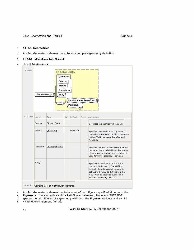
11.2 Geometries and Figures Graphics
78 Working Draft 1.0.1, September 2007
11.2.1 Geometries 1
A <PathGeometry> element constitutes a complete geometry definition. 2
11.2.1.1 <PathGeometry> Element 3
element PathGeometry 4
diagram
attributes Name Type Use Default Fixed Annotation
Figures ST_AbbrGeom Describes the geometry of the path.
FillRule ST_FillRule EvenOdd Specifies how the intersecting areas of
geometric shapes are combined to form a
region. Valid values are EvenOdd and
NonZero.
Transform ST_RscRefMatrix Specifies the local matrix transformation
that is applied to all child and descendant
elements of the path geometry before it is
used for filling, clipping, or stroking.
x:Key Specifies a name for a resource in a
resource dictionary. x:Key MUST be
present when the current element is
defined in a resource dictionary. x:Key
MUST NOT be specified outside of a
resource dictionary [M4.2].
annotation Contains a set of <PathFigure> elements.
A <PathGeometry> element contains a set of path figures specified either with the 5
Figures attribute or with a child <PathFigure> element. Producers MUST NOT 6
specify the path figures of a geometry with both the Figures attribute and a child 7
<PathFigure> element [M4.3]. 8
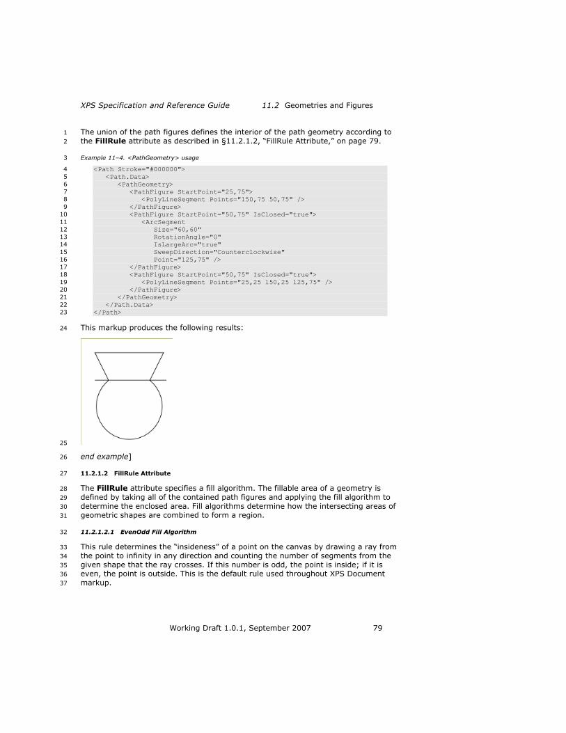
XPS Specification and Reference Guide 11.2 Geometries and Figures
Working Draft 1.0.1, September 2007 79
The union of the path figures defines the interior of the path geometry according to 1
the FillRule attribute as described in §11.2.1.2, ―FillRule Attribute,‖ on page 79. 2
Example 11–4. <PathGeometry> usage 3
<Path Stroke="#000000"> 4
<Path.Data> 5
<PathGeometry> 6
<PathFigure StartPoint="25,75"> 7
<PolyLineSegment Points="150,75 50,75" /> 8
</PathFigure> 9
<PathFigure StartPoint="50,75" IsClosed="true"> 10
<ArcSegment 11
Size="60,60" 12
RotationAngle="0" 13
IsLargeArc="true" 14
SweepDirection="Counterclockwise" 15
Point="125,75" /> 16
</PathFigure> 17
<PathFigure StartPoint="50,75" IsClosed="true"> 18
<PolyLineSegment Points="25,25 150,25 125,75" /> 19
</PathFigure> 20
</PathGeometry> 21
</Path.Data> 22
</Path> 23
This markup produces the following results: 24
25
end example] 26
11.2.1.2 FillRule Attribute 27
The FillRule attribute specifies a fill algorithm. The fillable area of a geometry is 28
defined by taking all of the contained path figures and applying the fill algorithm to 29
determine the enclosed area. Fill algorithms determine how the intersecting areas of 30
geometric shapes are combined to form a region. 31
11.2.1.2.1 EvenOdd Fill Algorithm 32
This rule determines the ―insideness‖ of a point on the canvas by drawing a ray from 33
the point to infinity in any direction and counting the number of segments from the 34
given shape that the ray crosses. If this number is odd, the point is inside; if it is 35
even, the point is outside. This is the default rule used throughout XPS Document 36
markup. 37

11.2 Geometries and Figures Graphics
80 Working Draft 1.0.1, September 2007
Figure 11–1. Fill using EvenOdd algorithm 1
2
11.2.1.2.2 NonZero Fill Algorithm 3
This rule determines the ―insideness‖ of a point on the canvas by drawing a ray from 4
the point to infinity in any direction and then examining the places where a segment 5
of the shape crosses the ray. Starting with a count of zero, add one each time a 6
segment crosses the ray from left to right and subtract one each time a path 7
segment crosses the ray from right to left. After counting the crossings, if the result 8
is zero then the point is outside the path; otherwise, it is inside. 9
Figure 11–2. Fill using NonZero algorithm 10
11
11.2.1.3 Figures Attribute 12
The <PathGeometry> element‘s Figures attribute can be used to describe the path 13
figures the geometry contains using abbreviated syntax (see §11.2.3, ―Abbreviated 14
Geometry Syntax,‖ on page 90) with the exception that the FillRule command MUST 15
NOT be used [M2.72]. 16

XPS Specification and Reference Guide 11.2 Geometries and Figures
Working Draft 1.0.1, September 2007 81
11.2.2 Figures 1
11.2.2.1 <PathFigure> Element 2
element PathFigure 3
diagram
attributes Name Type Use Default Fixed Annotation
IsClosed ST_Boolean false Specifies whether the path is closed. If set to
true, the stroke is drawn "closed," that is, the
last point in the last segment of the path
figure is connected with the point specified in
the StartPoint attribute, otherwise the stroke
is drawn "open," and the last point is not
connected to the start point. Only applicable
if the path figure is used in a <Path>
element that specifies a stroke.
StartPoint ST_Point required Specifies the starting point for the first
segment of the path figure.
IsFilled ST_Boolean true Specifies whether the path figure is used in
computing the area of the containing path
geometry. Can be true or false. When set to
false, the path figure is considered only for
stroking.
annotation Specifies a set of one or more segment elements defining a closed region.
A <PathFigure> element is composed of a set of one or more line or curve segments. 4
The segment elements define the shape of the path figure. The initial point of the 5
first segment element is specified as the StartPoint attribute of the path figure. The 6
last point of each segment element is the first point of the following segment 7
element. 8

11.2 Geometries and Figures Graphics
82 Working Draft 1.0.1, September 2007
Segment elements are: 1
<ArcSegment> 2
<PolyBezierSegment> 3
<PolyLineSegment> 4
<PolyQuadraticBezierSegment> 5
Line segments and curve segments SHOULD NOT be specified as zero-length [S4.1]. 6
If they are specified as zero-length, nothing is drawn, even if line caps would 7
normally be visible. For further details and exceptions, see 18, ―Rendering Rules.‖ 8
11.2.2.2 <ArcSegment> Element 9
element ArcSegment 10
diagram
attributes Name Type Use Default Fixed Annotation
Point ST_Point required Specifies the endpoint of the
elliptical arc.
Size ST_PointGE0 required Specifies the x and y radius of
the elliptical arc as an x,y pair.
RotationAngle ST_Double required Indicates how the ellipse is
rotated relative to the current
coordinate system.
IsLargeArc ST_Boolean required Determines whether the arc is
drawn with a sweep of 180 or
greater. Can be true or false.
SweepDirection ST_SweepDirection required Specifies the direction in which
the arc is drawn. Valid values
are Clockwise and
Counterclockwise.

XPS Specification and Reference Guide 11.2 Geometries and Figures
Working Draft 1.0.1, September 2007 83
IsStroked ST_Boolean true Specifies whether the stroke for
this segment of the path is
drawn. Can be true or false.
annotation Represents an elliptical arc between two points.
The <ArcSegment> element describes an elliptical arc. It is geometrically defined by 1
the intersection of two ellipses that have the same x radius and y radius. The ellipses 2
intersect at the starting and ending points of the arc. 3
Table 11–9. Arc segment definition 4
Term Description
Starting Point Implicitly defined by the previous point in the path figure
definition.
Ending Point Specified by the Point attribute.
Arc Size Defined by the Size attribute. This value consists of the comma-delimited x and y radii of the ellipses that will be used to define the arc. [Example: ―100,50‖ end example]
Rotation Angle Specified by the RotationAngle attribute, this determines how the ellipses defining the arc are rotated with respect to the x axis, in
degrees. Positive values are clockwise and negative values are counter-clockwise.
Large Arc Flag Specified by the IsLargeArc attribute, this flag indicates which of
the arc pairs created by the intersecting ellipses to use. When the flag is true, it uses the larger arc (arc length >= 180°), and when
it is false it uses the smaller arcs (arc length < 180°).
Sweep Direction Specified by the SweepDirection attribute, this flag determines which of the two possible arcs (selected by the Large Arc Flag) is
used. Beginning at the starting point, one arc proceeds in the positive (clockwise) direction, while the other proceeds in the
negative (counter-clockwise) direction.
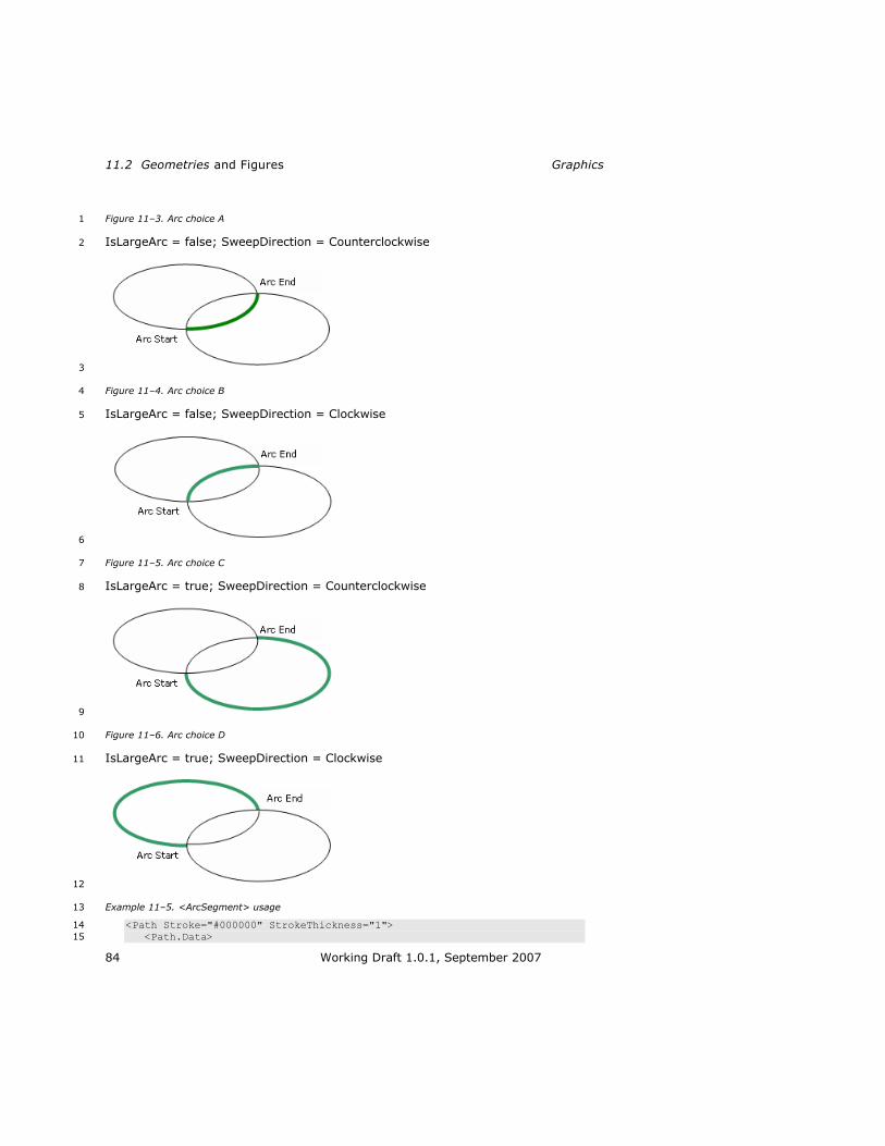
11.2 Geometries and Figures Graphics
84 Working Draft 1.0.1, September 2007
Figure 11–3. Arc choice A 1
IsLargeArc = false; SweepDirection = Counterclockwise 2
3
Figure 11–4. Arc choice B 4
IsLargeArc = false; SweepDirection = Clockwise 5
6
Figure 11–5. Arc choice C 7
IsLargeArc = true; SweepDirection = Counterclockwise 8
9
Figure 11–6. Arc choice D 10
IsLargeArc = true; SweepDirection = Clockwise 11
12
Example 11–5. <ArcSegment> usage 13
<Path Stroke="#000000" StrokeThickness="1"> 14
<Path.Data> 15

XPS Specification and Reference Guide 11.2 Geometries and Figures
Working Draft 1.0.1, September 2007 85
<PathGeometry> 1
<PathFigure StartPoint="10,10"> 2
<ArcSegment 3
Size="100,50" 4
RotationAngle="45" 5
IsLargeArc="true" 6
SweepDirection="Counterclockwise" 7
Point="200,100" /> 8
</PathFigure> 9
</PathGeometry> 10
</Path.Data> 11
</Path> 12
This markup generates the following arc: 13
14
end example] 15
11.2.2.2.1 Out-of-Range Attributes 16
The following guidelines are followed when encountering incompatible attribute 17
values on an <ArcSegment> element: 18
If the arc is impossible to render given the combination of radii specified in the 19
Size attribute and the angle of rotation specified in the RotationAngle 20
attribute, the ellipses are scaled equally until there is exactly one solution that 21
satisfies the arc requirements to pass through the specified Point attribute. 22
If the Point attribute is the same as the previous point in the path figure, the 23
segment is omitted. 24
If either the x or y radius in the Size attribute is 0, the segment is rendered as 25
a poly line segment with a single line segment to the x,y coordinates specified 26
by the Point attribute. 27
The x or y radius in the Size attribute MUST NOT be negative [M2.72]. 28
If the RotationAngle value is greater than 360, it is replaced by the value of 29
the RotationAngle modulo 360. If it is less than 0, it is replaced with a value 30
normalized to the range 0–360. 31

11.2 Geometries and Figures Graphics
86 Working Draft 1.0.1, September 2007
11.2.2.3 <PolyBezierSegment> Element 1
element PolyBezierSegment 2
diagram
attributes Name Type Use Default Fixed Annotation
Points ST_Points required Specifies control points for multiple Bézier
segments. Coordinate values within each pair
are comma-separated and additional
whitespace may appear. Coordinate pairs are
separated from other coordinate pairs by
whitespace.
IsStroked ST_Boolean true Specifies whether the stroke for this segment
of the path is drawn. Can be true or false.
annotation A series of Bézier segments.
The <PolyBezierSegment> element describes a set of cubic Bézier curves. Bézier 3
curves are drawn from the previous point in the path figure or the previous Bézier 4
curve in the segment and terminate at the third point (x3n,y3n) in the Points 5
attribute (where n is the curve being drawn). The tangents and curvature of each 6
Bézier curve are controlled by the first two control points (x3n-2,y3n-2 and x3n-1,y3n-1) in 7
the Points attribute. The Points attribute contains a multiple of three whitespace-8
delimited pairs of comma-delimited x,y values. 9
Example 11–6. <PolyBezierSegment> usage 10
<Path Stroke="#000000" StrokeThickness="1"> 11
<Path.Data> 12
<PathGeometry> 13
<PathFigure StartPoint="20,80"> 14
<PolyBezierSegment Points="70,0 120,160 170,80 120,0 70,160 15
20,80" /> 16
</PathFigure> 17
</PathGeometry> 18
</Path.Data> 19
</Path> 20

XPS Specification and Reference Guide 11.2 Geometries and Figures
Working Draft 1.0.1, September 2007 87
This markup generates the following results: 1
2
end example] 3
11.2.2.4 <PolyLineSegment> Element 4
element PolyLineSegment 5
diagram
attributes Name Type Use Default Fixed Annotation
Points ST_Points required Specifies a set of coordinates for the multiple
segments that define the poly line segment.
Coordinate values within each pair are
comma-separated and additional whitespace
may appear. Coordinate pairs are separated
from other coordinate pairs by whitespace.
IsStroked ST_Boolean true Specifies whether the stroke for this segment
of the path is drawn. Can be true or false.
annotation Specifies a set of points between which lines are drawn.
The <PolyLineSegment> element describes a polygonal drawing containing an 6
arbitrary number of individual vertices. The Points attribute defines the vertices and 7
contains whitespace-delimited pairs of comma-delimited x,y values. 8
Example 11–7. <PolyLineSegment> usage 9
<Path Stroke="#000000" StrokeThickness="1"> 10
<Path.Data> 11
<PathGeometry> 12
<PathFigure StartPoint="10,10"> 13
<PolyLineSegment Points="140,10 140,55 95,55 65,85 95,115 14
140,115 140,160 10,160" /> 15
</PathFigure> 16
</PathGeometry> 17
</Path.Data> 18
</Path> 19
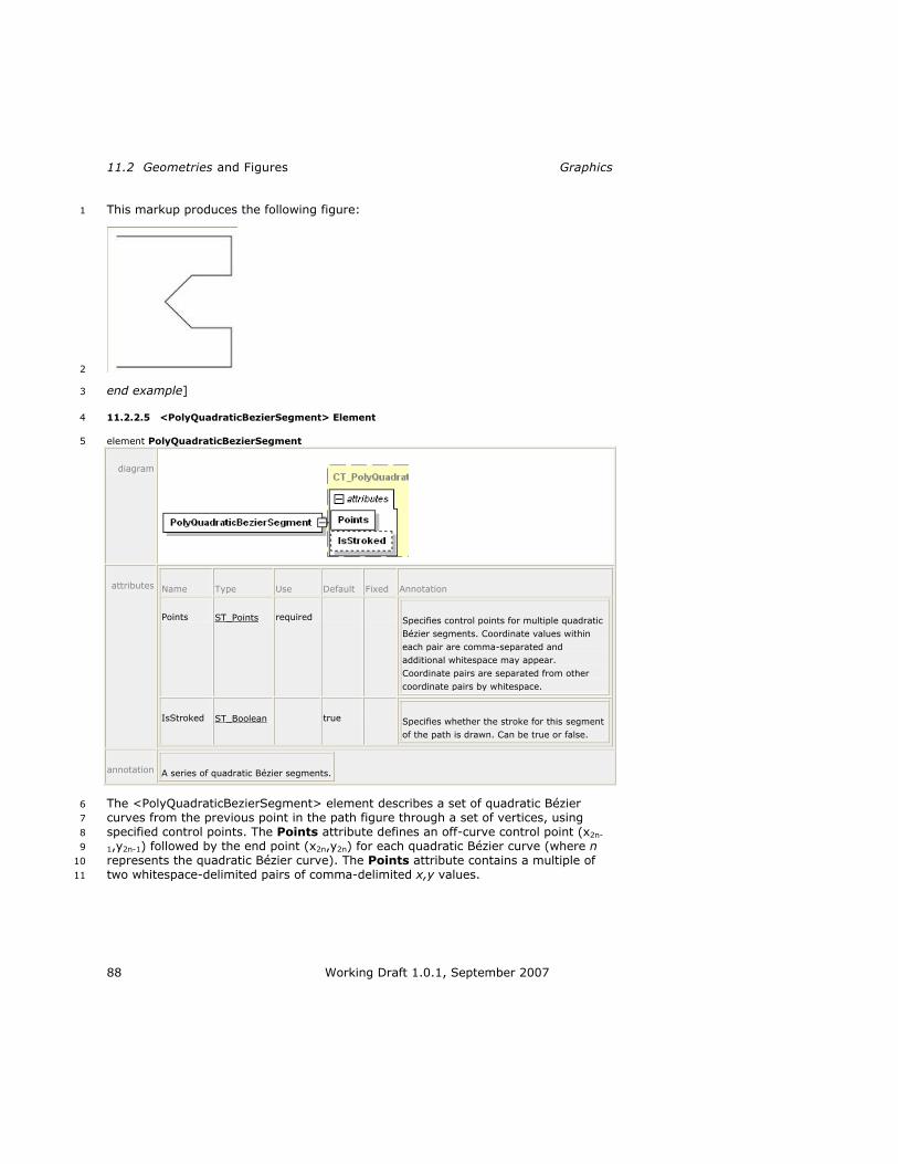
11.2 Geometries and Figures Graphics
88 Working Draft 1.0.1, September 2007
This markup produces the following figure: 1
2
end example] 3
11.2.2.5 <PolyQuadraticBezierSegment> Element 4
element PolyQuadraticBezierSegment 5
diagram
attributes Name Type Use Default Fixed Annotation
Points ST_Points required Specifies control points for multiple quadratic
Bézier segments. Coordinate values within
each pair are comma-separated and
additional whitespace may appear.
Coordinate pairs are separated from other
coordinate pairs by whitespace.
IsStroked ST_Boolean true Specifies whether the stroke for this segment
of the path is drawn. Can be true or false.
annotation A series of quadratic Bézier segments.
The <PolyQuadraticBezierSegment> element describes a set of quadratic Bézier 6
curves from the previous point in the path figure through a set of vertices, using 7
specified control points. The Points attribute defines an off-curve control point (x2n-8
1,y2n-1) followed by the end point (x2n,y2n) for each quadratic Bézier curve (where n 9
represents the quadratic Bézier curve). The Points attribute contains a multiple of 10
two whitespace-delimited pairs of comma-delimited x,y values. 11

XPS Specification and Reference Guide 11.2 Geometries and Figures
Working Draft 1.0.1, September 2007 89
Example 11–8. <PolyQuadraticBezierSegment> usage 1
<Path Stroke="#000000" StrokeThickness="1"> 2
<Path.Data> 3
<PathGeometry> 4
<PathFigure StartPoint="10,10"> 5
<PolyQuadraticBezierSegment Points="50,200 100,40 150,200 6
200,10" /> 7
</PathFigure> 8
</PathGeometry> 9
</Path.Data> 10
</Path> 11
This markup produces the following curve: 12
13
end example] 14
11.2.2.6 Closed <PathFigure> 15
If the IsClosed attribute of the <PathFigure> element is set to true, a straight line 16
is drawn from the last point in the last segment of the <PathFigure> element to the 17
StartPoint attribute of the <PathFigure> element. If the IsClosed attribute is 18
omitted, its default setting is ―false‖. 19
<PathFigure> elements used in filled <Path> elements or as Clip attributes are 20
implicitly closed. 21
Example 11–9. Closed <PathFigure> usage 22
The following markup shows the arc segment as shown in Example 11–5 with the 23
IsClosed attribute of the <PathFigure> element set to true. 24
<Path Stroke="#000000" StrokeThickness="1"> 25
<Path.Data> 26
<PathGeometry> 27
<PathFigure StartPoint="10,10" IsClosed="true"> 28
<ArcSegment 29
Size="100,50" 30
RotationAngle="45" 31
IsLargeArc="true" 32
SweepDirection="Counterclockwise" 33
Point="200,100" /> 34
</PathFigure> 35
</PathGeometry> 36
</Path.Data> 37
</Path> 38

11.2 Geometries and Figures Graphics
90 Working Draft 1.0.1, September 2007
This markup generates the following figure: 1
2
end example] 3
11.2.3 Abbreviated Geometry Syntax 4
Abbreviated geometry syntax MAY be used to specify a geometry of one or more 5
figures comprised of multiple segments [M2.72]. A geometry is specified with an 6
optional FillRule command (not allowed in the Figures attribute of a 7
<PathGeometry> element) followed by one or more figure definitions. Figure 8
definitions are specified with a Move command, a set of drawing commands to create 9
segments, and an optional Close command to create a closing segment. Drawing 10
commands include: 11
Line 12
Horizontal Line 13
Vertical Line 14
Cubic Bézier Curve 15
Quadratic Bézier Curve 16
Smooth Cubic Bézier Curve 17
Elliptical Arc 18
A command is represented by a single letter and is followed by zero or more 19
whitespace characters, which are followed by command parameters. Parameters are 20
whitespace-delimited. Points are specified as a comma-delimited pair with zero or 21
more whitespace characters. 22
Uppercase letters denote absolute values and lowercase letters denote relative 23
values. When relative coordinate values are specified, each coordinate pair expresses 24
an offset relative to the current endpoint (the previous command‘s terminating 25
coordinate pair). If a relative value is used for the first Move command, the current 26
endpoint is, by definition, 0,0. 27
If a relative value is used following a Close command, the current endpoint is the 28
first point of the previous figure. 29
If entering more than one drawing command of the same type sequentially, the 30
duplicate command entry MAY be omitted [M2.72]. [Example: ―L 100,200 300,400‖ 31
is equivalent to ―L 100,200 L 300,400‖. end example] The current endpoint is 32
determined as though each command appeared individually. 33

XPS Specification and Reference Guide 11.2 Geometries and Figures
Working Draft 1.0.1, September 2007 91
Values specifying coordinates can be real numbers. 1
For more information, see F, ―Abbreviated Geometry Syntax Algorithm.‖ 2
Table 11–10. Commands 3
Name Syntax Description Non-Abbreviated
Equivalent
FillRule F fFillRule Establishes the fill rule that should be used for this
geometry. A value of 0 is equivalent to a FillRule value
of EvenOdd; a value of 1 is equivalent to a FillRule value
of NonZero. The default value if this command is omitted is
0.
This command MUST appear
only as the first command in the abbreviated geometry syntax [M2.72]. This command MUST NOT be specified in the value of the Figures attribute of the <PathGeometry> element
[M2.72]. [Example: F 0 end
example]
<PathGeometry> FillRule attribute
Move M x,y
or m x,y
Establishes a new current endpoint. Every geometry
MAY specify one or more figures, and MAY be preceded
by a FillRule command where allowed [M2.72]. The first
figure in a geometry MUST begin with a Move command
[M2.72]. Subsequent Move
commands indicate the start of a new figure but MAY be omitted, indicating the current endpoint for the subsequent figure is the same as the end point of the previous figure [M2.72]. [Example: M 1.0,1.5 end example]
<PathFigure> StartPoint attribute
Line L x,y
or l x,y
Draws a straight line from the current point to the specified
point. [Example: L 20,30 end
example]
<PolyLineSegment> element
Horizontal Line
H x
or h x
Draws a horizontal line from the current endpoint to the specified x coordinate.
[Example: H 90 end example]
<PolyLineSegment> element

11.2 Geometries and Figures Graphics
92 Working Draft 1.0.1, September 2007
Name Syntax Description Non-Abbreviated
Equivalent
Vertical Line
V y
or v y
Draws a vertical line from the current endpoint to the specified y coordinate.
[Example: v 90 end example]
<PolyLineSegment> element
Cubic Bézier Curve
C x1,y1 x2,y2 x3,y3
or
c x1,y1 x2,y2 x3,y3
Draws a cubic Bézier curve from the current endpoint to
the specified point (x3,y3)
using the two specified control
points (x1,y1 and x2,y2). The
first control point determines the initial direction (tangent) of the curve, and the second
determines the terminating direction (tangent) of the
curve. [Example: C 100,200
200,400 300,200 end example]
<PolyBezierSegment> element
Quadrati
c Bézier Curve
Q x1,y1 x2,y2
or
q x1,y1 x2,y2
Draws a quadratic Bézier
curve from the current endpoint to the specified point
(x2,y2) using the specified
control point (x1,y1).
[Example: q 100,200 300,200
end example]
<PolyQuadratic
BezierSegment> element
Smooth
Cubic Bézier
Curve
S x1,y1 x2,y2
or
s x1,y1 x2,y2
Draws a cubic Bézier curve
from the current endpoint to
the specified point (x2,y2). The
first control point is assumed to be the reflection of the
second control point of the previous command, relative to
the current endpoint. If there is no previous command or if
the previous command was
not a Cubic Bézier Curve command or Smooth Cubic
Bézier Curve command, the first control point is assumed
to be coincident with the current endpoint. The second control point is specified by
x1,y1. [Example: S 100,200
200,300 end example]
<PolyBezierSegmen
t> element
Elliptical Arc
A xr,yr rx fArc fSweep
x,y
or
a xr,yr rx fArc fSweep
x,y
Draws an elliptical arc from the current endpoint to the
specified point (x,y). The size
and orientation of the ellipse
are defined by xr,yr. rx,xr
defines the x radius, yr defines
<ArcSegment> element

XPS Specification and Reference Guide 11.2 Geometries and Figures
Working Draft 1.0.1, September 2007 93
Name Syntax Description Non-Abbreviated
Equivalent
the y radius, and rx defines
the x-axis rotation in degrees, which indicates how the ellipse is rotated relative to
the current coordinate system. The center of the
ellipse is calculated automatically.
In most situations, four different arcs satisfy the
specified constraints. fArc and
fSweep indicate which arc to
use.
Of the four candidate arc sweeps, two represent large
arcs with sweeps of 180° or greater, and two represent
smaller arcs with sweeps less than 180°.
If fArc is 1, one of the two
larger arc sweeps is chosen. If
fArc is 0, one of the smaller
arc sweeps is chosen. No
other values of fArc are valid.
If fSweep is 1, the arc is drawn
in a positive-angle (clockwise)
direction. If fSweep is 0, the
arc is drawn in a negative-angle (counter-clockwise)
direction. No other values of
fSweep are valid. [Example: a
200,70 10 0 1 100,100 end
example]
Close Z or z Draws a straight line from the current endpoint to the first
point of the current figure and then ends the figure.
If the command following a Close command is a Move
command, the Move command specifies the initial point of the next figure. Otherwise, the next figure starts at the same initial point as the current figure.
<PathFigure> IsClosed attribute

11.2 Geometries and Figures Graphics
94 Working Draft 1.0.1, September 2007
Example 11–10. A path described using abbreviated syntax 1
The following markup demonstrates a simple path, which is drawn using the 2
abbreviated syntax: 3
<Path Stroke="#000000" Data="M 100,100 L 300,100 L 200,300 z" /> 4
end example] 5
11.2.3.1 Smooth Bézier Curve Abbreviated Syntax 6
Smooth Bézier curves specified with the abbreviated geometry syntax are basic cubic 7
Bézier curves with an implied first control point. This control point is coincident with 8
the endpoint of the previous segment unless the previous segment is also a Bézier 9
curve. In this case, the first control point of the smooth Bézier curve is a reflection of 10
the second control point of the previous curve segment around the start point of the 11
smooth Bezier curve segment, as shown below. 12
Example 11–11. Smooth Bézier curve 13
In the following example, C1 and C2 represent the first and second control points of 14
the first cubic Bézier curve segment, respectively. S1 represents the implied first 15
control point of the smooth Bézier curve segment. S2 represents the specified control 16
point of the smooth Bézier curve segment. I represents the inflection point around 17
which control point S1 is derived from control point C2. 18
19
The above diagram is generated with the following markup: 20
<Canvas RenderTransform="1.25,0,0,1.25,-40,20" > 21
<!-- Main Path --> 22
<Path Stroke="#000000" StrokeThickness="30" StrokeLineJoin="Round" 23
Data="M50,80 L100,80 C130,0 170,160 200,80 S270,160 300,80 L350,80"/> 24
<Path Stroke="#CCCCCC" StrokeThickness="2" 25
Data="M50,80 L100,80 C130,0 170,160 200,80 S270,160 300,80 L350,80"/> 26
<!-- C1 --> 27
<Path Stroke="#AAAAAA" StrokeThickness="1" Data="M 100,80 L 130,0" /> 28
<Path Stroke="#0000CC" StrokeThickness="5" StrokeStartLineCap="Round" 29
StrokeEndLineCap="Round" Data="M 130,0 L 130,0" /> 30
<Glyphs Fill="#000000" UnicodeString="C" OriginX="130" OriginY="15" 31
FontUri="../Resources/Fonts/Verdana.ttf" FontRenderingEmSize="10" 32
/> 33
<Glyphs Fill="#000000" UnicodeString="1" OriginX="138" OriginY="18" 34

XPS Specification and Reference Guide 11.2 Geometries and Figures
Working Draft 1.0.1, September 2007 95
FontUri="../Resources/Fonts/Verdana.ttf" FontRenderingEmSize="6" 1
/> 2
<!-- C2 --> 3
<Path Stroke="#AAAAAA" Data="M 200,80 L 170,160" /> 4
<Path Stroke="#0000CC" StrokeThickness="5" StrokeStartLineCap="Round" 5
StrokeEndLineCap="Round" Data="M 170,160 L 170,160" /> 6
<Glyphs Fill="#000000" UnicodeString="C" OriginX="175" 7
OriginY="175" FontUri="../Resources/Fonts/Verdana.ttf" 8
FontRenderingEmSize="10" /> 9
<Glyphs Fill="#000000" UnicodeString="2" OriginX="183" 10
OriginY="178" FontUri="../Resources/Fonts/Verdana.ttf" 11
FontRenderingEmSize="6" /> 12
<!-- S1 --> 13
<Path Stroke="#AAAAAA" StrokeThickness="2" 14
StrokeDashArray="0.75 0.75" Data="M 200,80 L 230,0" /> 15
<Path Stroke="#0000CC" StrokeThickness="5" StrokeStartLineCap="Round" 16
StrokeEndLineCap="Round" Data="M 230,0 L 230,0" /> 17
<Path Stroke="#FFFFFF" StrokeThickness="3" StrokeStartLineCap="Round" 18
StrokeEndLineCap="Round" Data="M 230,0 L 230,0" /> 19
<Glyphs Fill="#000000" UnicodeString="S" OriginX="230" OriginY="15" 20
FontUri="../Resources/Fonts/Verdana.ttf" FontRenderingEmSize="10" 21
/> 22
<Glyphs Fill="#000000" UnicodeString="1" OriginX="238" OriginY="18" 23
FontUri="../Resources/Fonts/Verdana.ttf" FontRenderingEmSize="6" 24
/> 25
<!-- S2 --> 26
<Path Stroke="#AAAAAA" StrokeThickness="1" Data="M 300,80 L 270,160" 27
/> 28
<Path Stroke="#0000CC" StrokeThickness="5" StrokeStartLineCap="Round" 29
StrokeEndLineCap="Round" Data="M 270,160 L 270,160" /> 30
<Glyphs Fill="#000000" UnicodeString="S" OriginX="275" OriginY="175" 31
FontUri="../Resources/Fonts/Verdana.ttf" FontRenderingEmSize="10" 32
/> 33
<Glyphs Fill="#000000" UnicodeString="2" OriginX="283" OriginY="178" 34
FontUri="../Resources/Fonts/Verdana.ttf" FontRenderingEmSize="6" 35
/> 36
<!-- Inflection --> 37
<Path Stroke="#FFFFFF" StrokeThickness="3" StrokeStartLineCap="Round" 38
StrokeEndLineCap="Round" Data="M 200,80 L 200,80" /> 39
<Glyphs Fill="#FFFFFF" UnicodeString="I" OriginX="203" OriginY="90" 40
FontUri="../Resources/Fonts/Verdana.ttf" FontRenderingEmSize="10" 41
/> 42
</Canvas> 43
end example] 44
11.2.3.2 Relative Commands and Curve Control Points 45
When using relative (lowercase) commands with the abbreviated geometry syntax, 46
each control point and end point are individually specified relative to the start point 47
of that segment. 48
Example 11–12. Relative commands and curves 49
The following markup describes a simple shape using cubic Bézier curves: 50
<Path Stroke="#000000" Data="M 50,20 L 150,20 C 250,75 170,130 120,100 51
C 70,70 90,110 130,160 Q 0,150 50,20" /> 52
This markup describes the same shape, using relative commands: 53
<Path Stroke="#000000" Data="M 50,20 l 100,0 c 100,55 20,110 -30,80 54
c -50,-30 -30,10 10,60 q -130,-10 -80,-140" /> 55

11.2 Geometries and Figures Graphics
96 Working Draft 1.0.1, September 2007
end example] 1

XPS Specification and Reference Guide 11.2 Geometries and Figures
Working Draft 1.0.1, September 2007 97
12. Text 1
A run of text sharing the same characteristics is represented by a <Glyphs> 2
element. Text runs are broken by line advances and formatting changes. The set of 3
properties on the <Glyphs> element allows for a complete description of the glyph 4
characteristics, such as the fill and opacity, as well as clipping information. The 5
<Glyphs> element allows specification of a Unicode string and supports bidirectional 6
and vertical text. 7
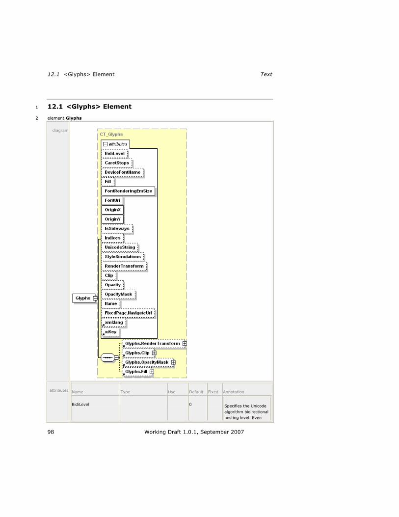
12.1 <Glyphs> Element Text
98 Working Draft 1.0.1, September 2007
12.1 <Glyphs> Element 1
element Glyphs 2
diagram
attributes Name Type Use Default Fixed Annotation
BidiLevel 0 Specifies the Unicode
algorithm bidirectional
nesting level. Even

XPS Specification and Reference Guide 12.1 <Glyphs> Element
Working Draft 1.0.1, September 2007 99
values imply left-to-
right layout, odd
values imply right-to-
left layout. Right-to-
left layout places the
run origin at the right
side of the first glyph,
with positive advance
widths (representing
advances to the left)
placing subsequent
glyphs to the left of
the previous glyph.
Valid values range
from 0 to 61,
inclusive.
CaretStops ST_CaretStops Identifies the positions
within the sequence of
Unicode characters at
which a text-selection
tool may place a text-
editing caret. Potential
caret-stop positions
are identified by their
indices into the UTF-
16 code units
represented by the
UnicodeString
attribute value.
When this attribute is
missing, the text in
the UnicodeString
attribute value MUST
be interpreted as
having a caret stop
between every
Unicode UTF-16 code
unit and at the
beginning and end of
the text [M5.1].
The value SHOULD
indicate that the caret
cannot stop in front of
most combining marks
or in front of the
second UTF-16 code
unit of UTF-16
surrogate pairs [S5.1].
DeviceFontName ST_UnicodeString Uniquely identifies a
specific device font.
The identifier is
typically defined by a
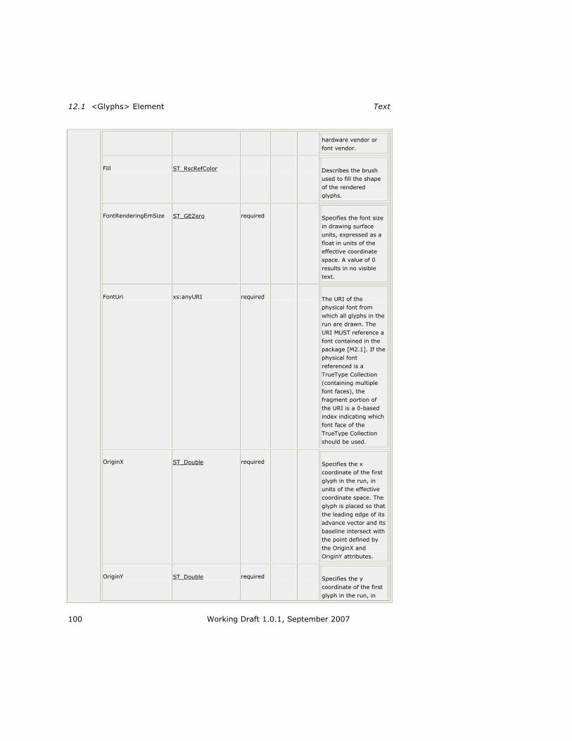
12.1 <Glyphs> Element Text
100 Working Draft 1.0.1, September 2007
hardware vendor or
font vendor.
Fill ST_RscRefColor Describes the brush
used to fill the shape
of the rendered
glyphs.
FontRenderingEmSize ST_GEZero required Specifies the font size
in drawing surface
units, expressed as a
float in units of the
effective coordinate
space. A value of 0
results in no visible
text.
FontUri xs:anyURI required The URI of the
physical font from
which all glyphs in the
run are drawn. The
URI MUST reference a
font contained in the
package [M2.1]. If the
physical font
referenced is a
TrueType Collection
(containing multiple
font faces), the
fragment portion of
the URI is a 0-based
index indicating which
font face of the
TrueType Collection
should be used.
OriginX ST_Double required Specifies the x
coordinate of the first
glyph in the run, in
units of the effective
coordinate space. The
glyph is placed so that
the leading edge of its
advance vector and its
baseline intersect with
the point defined by
the OriginX and
OriginY attributes.
OriginY ST_Double required Specifies the y
coordinate of the first
glyph in the run, in

XPS Specification and Reference Guide 12.1 <Glyphs> Element
Working Draft 1.0.1, September 2007 101
units of the effective
coordinate space. The
glyph is placed so that
the leading edge of its
advance vector and its
baseline intersect with
the point defined by
the OriginX and
OriginY attributes.
IsSideways ST_Boolean false Indicates that a glyph
is turned on its side,
with the origin being
defined as the top
center of the unturned
glyph.
Indices ST_Indices Specifies a series of
glyph indices and their
attributes used for
rendering the glyph
run. If the
UnicodeString
attribute specifies an
empty string (―‖ or
―{}‖) and the Indices
attribute is not
specified or is also
empty, a consumer
MUST generate an
error [M5.2].
UnicodeString ST_UnicodeString Contains the string of
text rendered by the
<Glyphs> element.
The text is specified as
Unicode code points.
StyleSimulations ST_StyleSimulations None Specifies a style
simulation. Valid
values are None,
ItalicSimulation,
BoldSimulation, and
BoldItalicSimulation.
RenderTransform ST_RscRefMatrix Establishes a new
coordinate frame for
the glyph run specified
by the <Glyphs>
element. The render
transform affects clip,
opacity mask, fill, x

12.1 <Glyphs> Element Text
102 Working Draft 1.0.1, September 2007
origin, y origin, the
actual shape of
individual glyphs, and
the advance widths.
The render transform
also affects the font
size and values
specified in the Indices
attribute.
Clip ST_RscRefAbbrGeomF Limits the rendered
region of the element.
Only portions of the
<Glyphs> element
that fall within the clip
region (even partially
clipped characters)
produce marks on the
page.
Opacity ST_ZeroOne 1.0 Defines the uniform
transparency of the
glyph element. Values
range from 0 (fully
transparent) to 1 (fully
opaque), inclusive.
Values outside of this
range are invalid.
OpacityMask ST_RscRef Specifies a mask of
alpha values that is
applied to the glyphs
in the same fashion as
the Opacity attribute,
but allowing different
alpha values for
different areas of the
element.
Name ST_Name Contains a string
value that identifies
the current element as
a named, addressable
point in the document
for the purpose of
hyperlinking.
FixedPage.NavigateUri xs:anyURI Associates a hyperlink
URI with the element.
May be a relative
reference or a URI
that addresses a

XPS Specification and Reference Guide 12.1 <Glyphs> Element
Working Draft 1.0.1, September 2007 103
resource that is
internal to or external
to the package.
xml:lang Specifies the default
language used for the
current element. The
language is specified
according to RFC
3066.
x:Key Specifies a name for a
resource in a resource
dictionary. x:Key
MUST be present
when the current
element is defined in a
resource dictionary.
x:Key MUST NOT be
specified outside of a
resource dictionary
[M5.3].
annotation Represents a run of text from a single font.
The <Glyphs> element represents a run of uniformly-formatted text from a single 1
font. It provides information necessary for accurate rendering and supports search 2
and selection features in viewing consumers. 3
If the Fill property is not specified, the <Glyphs> element has no visible effect. 4
Some properties of the <Glyphs> element are composable, meaning that the 5
markings rendered to the page are determined by a combination of the property and 6
all the like-named properties of the <Glyphs> element‘s parent and ancestor 7
elements. For details, see 14, ―Common Properties.‖ 8

12.1 <Glyphs> Element Text
104 Working Draft 1.0.1, September 2007
12.1.1 Glyph Metrics 1
Each glyph defines metrics that specify how it aligns with other glyphs. The metrics 2
are illustrated below. 3
Figure 12–1. Glyph metrics 4
5
Figure 12–2. Upright (usually horizontal) glyph metrics 6
7

XPS Specification and Reference Guide 12.1 <Glyphs> Element
Working Draft 1.0.1, September 2007 105
Figure 12–3. Sideways (usually vertical) glyph metrics 1
2
In general, glyphs within a font are either base glyphs or combining marks that may 3
be attached to base glyphs. Base glyphs usually have an advance width that is non-4
zero, and a 0,0 offset vector. Combining marks usually have a zero advance width. 5
The offset vector can be used to adjust the position of a combining mark and, 6
therefore, may have a non-0,0 value for combining marks. 7
The position of each glyph in the glyph run is controlled by the following values: 8
Origin. Each glyph is assumed to be given a nominal origin. For the first glyph 9
in the run, this is the origin of the run. 10
Advance Width. The advance width for each glyph provides the origin of the 11
next glyph relative to the origin of the current glyph. The advance vector is 12
drawn in the direction of the run progression. 13
Glyph Offset (Base or Mark). The glyph offset vector adjusts the position of 14
this glyph relative to its nominal origin. The orientation of the glyph offset 15
vector is not affected by the value of the IsSideways attribute, but is affected 16
by the value of the BidiLevel attribute. 17
12.1.2 Mapping Code Units to Glyphs 18
A Unicode scalar value in a UnicodeString attribute is typically represented by a 19
single UTF-16 code unit and has a single corresponding glyph representation in the 20
font. More complex mapping scenarios are common in non-Latin scripts: a single 21
Unicode scalar value may map to two UTF-16 code units, multiple UTF-16 code units 22
may map to a single glyph, single UTF-16 code units may map to multiple glyphs 23
based on context, and multiple UTF-16 code units may map indivisibly to multiple 24
glyphs. In these cases, the clusters of UTF-16 code units are mapped using a cluster 25
map. 26
The cluster map contains one entry for each UTF-16 code unit in the UnicodeString 27
attribute. Each entry specifies the offset of the first glyph that represents the cluster 28
of UTF-16 code units. 29

12.1 <Glyphs> Element Text
106 Working Draft 1.0.1, September 2007
12.1.2.1 One-to-One Mappings 1
When each UTF-16 code unit is represented by exactly one glyph, the cluster map 2
entries are 0, 1, 2, and so on. 3
Example 12–1. One-to-one cluster map 4
Each character in the word ―file‖ is represented by a single glyph. 5
6
end example] 7
12.1.2.2 Many-to-One Mappings 8
When two or more UTF-16 code units map to a single glyph, the entries for those 9
UTF-16 code units specify the offset of that glyph in the glyph index buffer. 10
Example 12–2. Many-to-one cluster map 11
In the following mapping, the f and i characters are replaced by a ligature. 12
13
end example] 14

XPS Specification and Reference Guide 12.1 <Glyphs> Element
Working Draft 1.0.1, September 2007 107
12.1.2.3 One-to-Many Mappings 1
When one UTF-16 code unit maps to two or more glyphs, the value in the cluster 2
map for that UTF-16 code unit references the first glyph in the Indices attribute that 3
represents that UTF-16 code unit. 4
Example 12–3. One-to-many cluster map 5
The Thai Sara Am character contains a part that sits on top of the previous base 6
character (the ring), and a part that sits to the right of the base character (the 7
hook). When Thai text is micro-justified, the hook is spaced apart from the base 8
character, while the ring remains on top of the base character. Many fonts encode 9
the ring and the hook as separate glyphs. 10
11
The markup appears as follows: 12
<Glyphs 13
FontUri="../Resources/Fonts/browau.ttf" 14
UnicodeString="ภ้ำ!" 15
Indices="153;106,,,16;(1:2)124;198;4" 16
OriginX="10" OriginY="60" 17
FontRenderingEmSize="70" 18
Fill="#000000"/> 19
The markup above is rendered as follows: 20
21
end example] 22
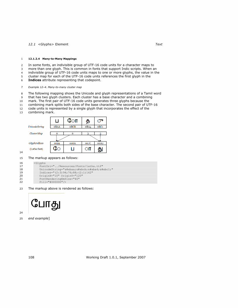
12.1 <Glyphs> Element Text
108 Working Draft 1.0.1, September 2007
12.1.2.4 Many-to-Many Mappings 1
In some fonts, an indivisible group of UTF-16 code units for a character maps to 2
more than one glyph. This is common in fonts that support Indic scripts. When an 3
indivisible group of UTF-16 code units maps to one or more glyphs, the value in the 4
cluster map for each of the UTF-16 code units references the first glyph in the 5
Indices attribute representing that codepoint. 6
Example 12–4. Many-to-many cluster map 7
The following mapping shows the Unicode and glyph representations of a Tamil word 8
that has two glyph clusters. Each cluster has a base character and a combining 9
mark. The first pair of UTF-16 code units generates three glyphs because the 10
combining mark splits both sides of the base character. The second pair of UTF-16 11
code units is represented by a single glyph that incorporates the effect of the 12
combining mark. 13
14
The markup appears as follows: 15
<Glyphs 16
FontUri="../Resources/Fonts/latha.ttf" 17
UnicodeString="போது" 18
Indices="(2:3)94;76;88;(2:1)162" 19
OriginX="10" OriginY="120" 20
FontRenderingEmSize="40" 21
Fill="#000000"/> 22
The markup above is rendered as follows: 23
24
end example] 25

XPS Specification and Reference Guide 12.1 <Glyphs> Element
Working Draft 1.0.1, September 2007 109
12.1.3 Indices Attribute 1
The <Glyphs> element MAY have an Indices attribute [M2.72]. The glyph 2
specifications within the Indices attribute are OPTIONAL [M2.72]. The GlyphIndex 3
portion of the Indices attribute MAY be used to specify a series of glyphs, complex 4
character-to-glyph cluster mappings, or a combination of both [M2.72]. The Indices 5
attribute MAY also include glyph placement information [M2.72]. 6
Within the Indices attribute, each glyph specification is separated by a semicolon. 7
The Indices attribute MUST adhere to the glyph specification syntax as follows 8
[M2.72]: 9
GlyphIndices = *1GlyphMapping *( ";" *1GlyphMapping ) 10
GlyphMapping = *1([ClusterMapping] GlyphIndex) [GlyphMetrics] 11
ClusterMapping = "(" ClusterCodeUnitCount [":" ClusterGlyphCount] ")" 12
ClusterCodeUnitCount = 1*DIGIT 13
ClusterGlyphCount = 1*DIGIT 14
GlyphIndex = *DIGIT 15
GlyphMetrics = "," *1AdvanceWidth ["," *1uOffset ["," vOffset]] 16
AdvanceWidth = ["+"] RealNum 17
uOffset = ["+" | "-"] RealNum 18
vOffset = ["+" | "-"] RealNum 19
RealNum = ((1*DIGIT ["." 1*DIGIT]) | ("." 1*DIGIT)) [Exponent] 20
Exponent = *1( ("E"|"e") ("+"|"-") 1*DIGIT ) 21
The sum of the code unit counts for all the GlyphMapping entries in the Indices 22
attribute MUST NOT exceed the number of UTF-16 code units in the UnicodeString 23
attribute if the UnicodeString attribute is specified and does not contain an empty 24
value (―‖ or ―{}‖). If a ClusterMapping is not specified within a GlyphMapping entry, 25
the code unit count is 1. If the Indices attribute specifies a GlyphIndex that does 26
not exist in the font, the consumer MUST generate an error [M5.4]. If the Indices 27
attribute is specified, the values provided MUST be used in preference to values 28
determined from the UnicodeString attribute alone [M5.23]. 29
Table 12–1. Glyph specifications 30
Name Description
GlyphIndex Index of the glyph (16-bit) in the physical font. The entry MAY be empty [M2.72], in which case the glyph index is determined by looking up the UTF-16 code unit in the font character map table. If
there is not a one-to-one mapping between code units and the glyph indices, this entry MUST be specified [M5.5].
In cases where character-to-glyph mappings are not one-to-one, a cluster mapping specification precedes the glyph index (further described below).
AdvanceWidth Advance width indicating placement for the subsequent glyph, relative to the origin of the current glyph. Measured in direction of advance as defined by the IsSideways and BidiLevel attributes. Base glyphs generally have a non-zero advance width and combining glyphs have a zero advance width.
Advance width is measured in hundredths of the font em size. The default value is defined in the horizontal metrics font table (hmtx) if the IsSideways attribute is specified as false or the vertical metrics font table (vmtx) if the IsSideways attribute is specified as true. Advance width is a real number with units specified in

12.1 <Glyphs> Element Text
110 Working Draft 1.0.1, September 2007
hundredths of an em.
So that rounding errors do not accumulate, the advance MUST be calculated as the exact unrounded origin of the subsequent glyph minus the sum of the calculated (that is, rounded) advance widths of the preceding glyphs [M5.6].
The advance MUST be 0 or greater [M2.72]. The right-to-left writing direction can be specified using the BidiLevel attribute.
uOffset, vOffset Offset in the effective coordinate space relative to glyph origin to move this glyph (x offset for uOffset and –y offset for vOffset. The sign of vOffset is reversed from the direction of the y axis. A positive vOffset value shifts the glyph by a negative y offset and vice versa.). Used to attach marks to base characters. The value is added to the nominal glyph origin calculated using the advance width to generate the actual origin for the glyph. The setting of the IsSideways attribute does not change the interpretation of uOffset
and vOffset.
Measured in hundredths of the font em size. The default offset
values are 0.0,0.0. uOffset and vOffset are real numbers.
Base glyphs generally have a glyph offset of 0.0,0.0. Combining
glyphs generally have an offset that places them correctly on top of the nearest preceding base glyph.
For left-to-right text, a positive uOffset value points to the right;
for right-to-left text, a positive uOffset value points to the left.
Example 12–1. Using indices to specify advance width 1
The following Indices attribute specifies that the seventh glyph in the Unicode string 2
has an advance width of 40: 3
Indices = ";;;;;;,40" 4
end example] 5
12.1.3.1 Specifying Character-to-Glyph Mappings 6
A cluster map specification MAY precede the glyph specification for the first glyph of 7
the cluster [M2.72]. 8
Empty Indices attribute values indicate that the corresponding UTF-16 code unit 9
within the Unicode string has a one-to-one relationship with the glyph index as 10
specified by the character mapping table within the font. 11
Cluster maps that specify 0:n or n:0 mappings are invalid. 12
See the glyph specification syntax above for details of how to specify cluster maps. 13
Table 12–2. Portions of the cluster specification 14
Name Description
ClusterCodeUnitCount Number of UTF-16 code units that combine to form this cluster. One or more code units may be specified. Default value is 1.
ClusterGlyphCount Number of glyph indices that combine to form this cluster.

XPS Specification and Reference Guide 12.1 <Glyphs> Element
Working Draft 1.0.1, September 2007 111
One or more indices may be specified. Default value is 1.
Example 12–2. Using the Indices attribute to specify glyph replacement for a cluster 1
The following Indices attribute specifies that the sixth and seventh UTF-16 code 2
units in the Unicode string should be replaced by a single glyph having an index of 3
191: 4
Indices = ";;;;;(2:1)191" 5
end example] 6
12.1.4 UnicodeString Attribute 7
The UnicodeString attribute holds the array of Unicode scalar values that are 8
represented by the current <Glyphs> element. Specifying a Unicode string is 9
RECOMMENDED, as it supports searching, selection, and accessibility [S5.5]. If the 10
Unicode string contains Unicode scalar values that require two UTF-16 code units, a 11
cluster map with a many-to-one or many-to-many mapping MUST be specified for 12
the values [M5.5]. 13
The standard XML escaping mechanisms are used to specify XML-reserved 14
characters. An additional mechanism MUST be used to escape a UnicodeString 15
attribute value that begins with an open brace (―{‖) [M5.7]. 16
In order to use an open brace at the beginning of the Unicode string, it MUST be 17
escaped with a prefix of ―{}‖ [M5.7]. If the UnicodeString attribute value starts 18
with ―{}‖, consumers MUST ignore those first two characters in processing the 19
Unicode string and in calculating index positions for the characters of the Unicode 20
string [M5.7]. 21
If the UnicodeString attribute specifies an empty string (―‖ or ―{}‖), and the 22
Indices attribute is missing or is also empty, it MUST be treated as an error [M5.2]. 23
If the UnicodeString attribute contains a Unicode code unit that cannot be mapped 24
to a glyph index via a cmap table in the font and there is no corresponding 25
GlyphIndex entry in the Indices attribute, the consumer MUST display the .notdef 26
glyph [M5.9]. 27
Producers MAY include Unicode control marks in the Unicode string [O5.1]. Such 28
marks include control codes, layout controls, invisible operators, deprecated format 29
characters, variation selectors, non-characters, and specials, according to their 30
definition within the Unicode specification. If producers include control marks in the 31
Unicode string, they SHOULD include an Indices attribute to specify glyph indices 32
and/or character-to-glyph mapping information for the control marks [S5.2]. In the 33
absence of such information, consumers MUST treat Unicode control marks like 34
ordinary characters and render the glyphs to which the Unicode control marks are 35
mapped in the CMAP table [M5.10]. The resulting glyphs might produce an 36
inappropriate rendering of the original Unicode string. 37
Producers MAY choose to generate UnicodeString attribute values that are not 38
normalized by any Unicode-defined algorithm [O5.2]. Because advance-widths, glyph 39
indices, and caret-stops are associated with the generated Unicode string, consumers 40
MUST NOT normalize the UnicodeString attribute value to produce an internal 41
representation [M5.11]. See §9.1.7.5, ―Non-Standard Font Compatibility Encoding,‖ 42
on page 35 for details and exceptions. 43

12.1 <Glyphs> Element Text
112 Working Draft 1.0.1, September 2007
12.1.5 StyleSimulations Attribute 1
Synthetic style simulations can be applied to the shape of the glyphs by using the 2
StyleSimulations attribute. Style simulations can be applied in addition to the 3
designed style of a font. The default value for the StyleSimulations attribute is 4
None, in which case the shapes of glyphs are not modified from their original design. 5
When the StyleSimulations value is specified as BoldSimulation, synthetic 6
emboldening is applied by geometrically widening the strokes of glyphs by 1% of the 7
em size, so that the centers of strokes remain at the same position. This leaves the 8
baseline origin unmodified. The black box grows 1% all around for a total of 2% 9
horizontal and 2% vertical. As a result, the character height and the advance width 10
of each glyph are increased by 2% of the em size. Producers MUST lay out 11
algorithmically emboldened glyphs using advance widths that are 2% of the em size 12
larger than when not algorithmically emboldened [M5.12]. 13
Consumers MUST implement the effect of algorithmic emboldening such that the 14
black box of the glyph grows by 2% of the em size [M5.13]. When advance widths 15
are omitted from the markup and the glyphs are algorithmically emboldened, the 16
advance widths obtained from the horizontal metrics font table (if IsSideways is 17
false) or the vertical metrics font table (if IsSideways is true) of the font MUST be 18
increased by 2% of the em size [M5.13]. 19
When StyleSimulations is specified as ItalicSimulation, synthetic italicizing is 20
applied to glyphs with an IsSideways value of false by skewing the top edge of the 21
alignment box of the character by 20° to the right, relative to the baseline of the 22
character. Glyphs with an IsSideways value of true are italicized by skewing the 23
right edge of the alignment box of the character by 20° down, relative to the 24
baseline origin of the glyph. The character height and advance width are not 25
modified. Producers MUST lay out algorithmically italicized glyphs using exactly the 26
same advance widths as when not algorithmically italicized [M5.14]. 27
When StyleSimulations is specified as BoldItalicSimulation, both BoldSimulation 28
and ItalicSimulation are applied, in order. 29
12.1.6 IsSideways Attribute 30
Glyphs for text in vertical writing systems are normally represented by rotating the 31
coordinate system and using the IsSideways attribute. <Glyphs> elements with the 32
IsSideways attribute set to true will be rotated 90° counter-clockwise and placed so 33
that the sideways baseline origin is coincident with the nominal origin of the 34
character (within the glyph-local coordinate space), as modified by the offset vector 35
in the Indices attribute. The advance vector places the nominal origin of the next 36
character a distance along the direction of progression of the run. The direction of 37
the advance vector is unaffected by IsSideways, however the method by which the 38
size of the advance vector is chosen is different. 39
[Example: To represent a run of characters top to bottom on a page, a render 40
transform can be used to rotate the <Glyphs> coordinate system 90° clockwise. 41
OriginX and OriginY can be used to specify a position at the top of the column of 42
text. Text from a vertical writing system can then be written using <Glyphs> 43
elements with the IsSideways attribute set to true. The individual glyphs appear in 44
the normal orientation because the rotation effected by the IsSideway attribute 45
undoes the effect of the render transform. end example] 46

XPS Specification and Reference Guide 12.1 <Glyphs> Element
Working Draft 1.0.1, September 2007 113
Text from horizontal writing systems can be included in the column by using 1
<Glyphs> elements without specifying IsSideways, or using a value of false for it. 2
The rotated coordinate system makes them appear top to bottom on the page, but 3
with the glyphs rotated to the right. 4
If alternate vertical character representations are available in the font, the producer 5
SHOULD use those and provide their glyph indices in the Indices attribute [S5.3]. 6
12.1.6.1 Calculating Sideways Text Origin and Advance Width 7
The formulas below describe the method used to calculate each glyph‘s nominal 8
origin, which is used for positioning the glyphs on the fixed page and for calculating 9
the default advance width for each glyph. 10
The origin is the top center of the unturned glyph. The x origin of the unturned glyph 11
is calculated to be exactly one-half the advance width of the glyph, as specified in 12
the horizontal metrics table of the font. This formula is expressed as follows (in 13
pseudocode): 14
TopOriginX = hmtx.advanceWidth[GlyphIndex] / 2 15
If the font is a CFF OpenType font, the y origin of the unturned glyph is determined 16
from the vertical origin (vorg) table for the font, which may be specified for a 17
particular glyph index but falls back to the default vertical origin if the glyph index is 18
not present in the vertical origin table. This formula is expressed as follows (in 19
pseudocode): 20
TopOriginY = vorg.vertOriginY[glyphIndex] 21
or: 22
TopOriginY = vorg.defaultVertOriginY 23
If the vertical origin table is not present, the glyph data (glyf) and vertical metrics 24
(vmtx) font tables are consulted. The glyph bounding box is retrieved from the glyph 25
data table and added to the top side-bearing for the glyph, specified in the vertical 26
metrics table. This formula is expressed as follows (in pseudocode): 27
TopOriginY = glyf.yMax[glyphIndex] + vmtx.topSideBearing[glyphIndex] 28
[Note: CFF fonts do not contain the glyf.yMax information; instead the yMax for each 29
glyph is computed by calculating the top of the glyph‘s bounding box from the CFF 30
charstring data. end note] 31
If the vertical metrics font table does not exist but the Windows-specific metrics 32
(OS/2) table does exist, the latter table is consulted and the sTypoAscender value is 33
used. This formula is expressed as follows (in pseudocode): 34
TopOriginY = os/2.sTypoAscender 35
Descender = abs(os/2.typoDescender) 36
In all other circumstances, the Ascender value from the horizontal header (hhea) 37
table is used. This formula is expressed as follows (in pseudocode): 38
TopOriginY = hhea.Ascender 39
Descender = abs(hhea.Descender) 40
Finally, the advance width for sideways text is computed as follows (in pseudocode), 41
unless specifically overridden by the Indices attribute: 42

12.1 <Glyphs> Element Text
114 Working Draft 1.0.1, September 2007
AdvanceWidth = TopOriginY + Descender 1
12.1.6.2 IsSideways and BidiLevel Effects on Glyph Positioning 2
Right-to-left text (BidiLevel attribute value of 1) changes the direction of the 3
AdvanceWidth and uOffset (horizontal offset) values of the Indices attribute, as well 4
as the position of the glyph origin. Vertical text (IsSideways attribute set to true) 5
changes the position of the glyph origin. 6
Producers MUST NOT specify text that is both right-to-left (BidiLevel attribute value 7
of 1) and vertical (IsSideways attribute set to true) [M5.15]. 8
Table 12–3. IsSideways and BidiLevel effects on origin placement 9
IsSideways BidiLevel Glyph origin Direction of advance width
and positive uOffset
Horizontal (false)
Left-to-right
(0)
Left end of horizontal advance vector along Latin
baseline
To the right
Horizontal (false)
Right-to-left
(1)
Right end of horizontal advance vector along Latin
baseline
To the left
Vertical (true)
Left-to-right (0)
Top end of vertical advance vector through the glyph centerline
To the right
Vertical (true)
Right-to-left (1)
Invalid combination

XPS Specification and Reference Guide 12.1 <Glyphs> Element
Working Draft 1.0.1, September 2007 115
Example 12–3. Text with positive uOffset and vOffset Indices values 1
In this example, the position of the glyphs is shown relative to the origin shown at 2
the crossed lines centered at 100,100. The text in gray shows where this text would 3
be rendered without modification of the uOffset and vOffset value of the Indices 4
attributes. 5
<Glyphs Fill="#000000" FontRenderingEmSize="48" 6
OriginX="100" OriginY="100" 7
UnicodeString="AFQ" 8
Indices=";,100,30,10;" 9
FontUri="../Resources/Fonts/Arial.ttf" /> 10
11
end example] 12
Example 12–4. Right-to-left text (odd BidiLevel) 13
The markup for this example matches the previous example, except the BidiLevel 14
attribute is set to 1. Note the change in the origin, and the reversal of the glyph 15
advance direction. 16
<Glyphs Fill="#000000" FontRenderingEmSize="48" 17
OriginX="100" OriginY="100" 18
UnicodeString="AFQ" 19
Indices=";,100,30,10;" 20
BidiLevel="1" 21
FontUri="../Resources/Fonts/Arial.ttf" /> 22
23

12.1 <Glyphs> Element Text
116 Working Draft 1.0.1, September 2007
end example] 1
Example 12–5. Sideways text (IsSideways set to true) 2
This example shows the IsSideways attribute set to true. The BidiLevel must be 3
even when the IsSidways attribute is set to true [M5.15]. Note that the origin has 4
changed to be the top-center of the first glyph, with each glyph rotated 90° counter-5
clockwise. The interpretation of the advance direction and uOffset and vOffset values 6
in the Indices attribute are otherwise unchanged. 7
<Glyphs Fill="#000000" FontRenderingEmSize="48" 8
OriginX="100" OriginY="100" 9
UnicodeString="AFQ" 10
Indices=";,100,30,10;" 11
IsSideways="true" 12
FontUri="../Resources/Fonts/Arial.ttf" /> 13
14
end example] 15
Example 12–6. Vertical text 16
The markup for this example matches the previous example, with the addition of a 17
render transformation to rotate and position the element as vertical text. For more 18
information on render transformations, see §14.4, ―Positioning Content,‖ on page 19
185. 20
<Glyphs Fill="#000000" FontRenderingEmSize="48" 21
OriginX="100" OriginY="100" 22
UnicodeString="AFQ" 23
Indices=";,100,30,10;" 24
IsSideways="true" 25
FontUri="../Resources/Fonts/Arial.ttf" 26
RenderTransform="0,1,-1,0,200,0" /> 27
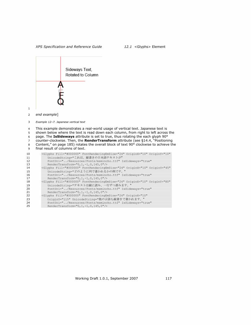
XPS Specification and Reference Guide 12.1 <Glyphs> Element
Working Draft 1.0.1, September 2007 117
1
end example] 2
Example 12–7. Japanese vertical text 3
This example demonstrates a real-world usage of vertical text. Japanese text is 4
shown below where the text is read down each column, from right to left across the 5
page. The IsSideways attribute is set to true, thus rotating the each glyph 90° 6
counter-clockwise. Then, the RenderTransform attribute (see §14.4, ―Positioning 7
Content,‖ on page 185) rotates the overall block of text 90° clockwise to achieve the 8
final result of columns of text. 9
<Glyphs Fill="#000000" FontRenderingEmSize="24" OriginX="10" OriginY="10" 10
UnicodeString="これは、縦書きの日本語テキストが" 11
FontUri="../Resources/Fonts/msmincho.ttf" IsSideways="true" 12
RenderTransform="0,1,-1,0,145,0"/> 13
<Glyphs Fill="#000000" FontRenderingEmSize="24" OriginX="10" OriginY="45" 14
UnicodeString="どのように列で書かれるかの例です。" 15
FontUri="../Resources/Fonts/msmincho.ttf" IsSideways="true" 16
RenderTransform="0,1,-1,0,145,0"/> 17
<Glyphs Fill="#000000" FontRenderingEmSize="24" OriginX="10" OriginY="80" 18
UnicodeString="テキストは縦に読み、一行ずつ進みます。" 19
FontUri="../Resources/Fonts/msmincho.ttf" IsSideways="true" 20
RenderTransform="0,1,-1,0,145,0"/> 21
<Glyphs Fill="#000000" FontRenderingEmSize="24" OriginX="10" 22
OriginY="115" UnicodeString="他の言語も縦書きで書かれます。" 23
FontUri="../Resources/Fonts/msmincho.ttf" IsSideways="true" 24
RenderTransform="0,1,-1,0,145,0"/> 25

12.1 <Glyphs> Element Text
118 Working Draft 1.0.1, September 2007
This markup is rendered as follows: 1
2
end example] 3
12.1.7 DeviceFontName Attribute 4
Printer device fonts are specified by the DeviceFontName attribute. Device 5
manufacturers define the values for this attribute. Producers SHOULD NOT produce 6
markup that will result in different rendering between consumers using the 7
embedded font to render and consumers using the device font to render [S5.4]. 8
Consumers that understand the device font name MAY ignore the embedded font and 9
use the device-resident version [O5.3]. By definition, a consumer ―understands‖ a 10
printer device font if it can unambiguously correlate the device font name to a set of 11
font metrics resident on the device. If a consumer does not understand the specified 12
device font name, it MUST render the embedded version of the font [M5.16]. 13
When rendering a printer device font, consumers MUST use the UnicodeString 14
attribute and ignore the glyph index components of the Indices attribute [M5.17]. 15
The consumer MUST still honor the advance width and x,y offset values present in 16
the Indices attribute [M5.18]. 17
For producers, a <Glyphs> element with a specified device font name MUST have 18
exactly one Indices glyph per character in the UnicodeString attribute. Its Indices 19

XPS Specification and Reference Guide 12.1 <Glyphs> Element
Working Draft 1.0.1, September 2007 119
attribute MUST NOT include any cluster specifications. If the Indices attribute 1
includes a cluster mapping, the consumer MUST NOT use the device font and MUST 2
render the embedded version of the font [M5.19]. This means that a device font 3
cannot be used for characters outside the basic multilingual plane (BMP). 4
If a device font name is specified, each of the <Glyphs> element‘s Indices glyphs 5
MUST include a specified advance width and MUST include specified x and y offset 6
values if they are non-zero [M5.20]. 7
12.1.8 xml:lang Attribute 8
XPS Document consumers may need to override the default language for a specific 9
run of glyphs, particularly in multilingual documents. The language defaults to the 10
value specified for the xml:lang attribute of the <FixedPage> element but MAY be 11
overridden by an xml:lang attribute on a <Glyphs> element [M2.72]. For larger 12
blocks of text, the producer MAY specify the xml:lang attribute on the <Canvas> 13
element [M2.72]. 14
The language specified does not affect rendering of <Glyphs> elements, but it can 15
be used by consumers for searching or selecting text. For more information, 16
see §9.3.5, ―Language,‖ on page 47. 17
12.1.9 CaretStops Attribute 18
The CaretStops attribute contains an array of Boolean bit-flags, which is 19
represented as a string of hexadecimal characters. The flags indicate whether it is 20
legal to place the caret before the corresponding UTF-16 code unit in the 21
UnicodeString attribute. (―Before‖ refers to a logical placement, not a physical 22
placement.) [Example: If the flag is set in right-to-left text, the caret can be placed 23
before (to the right of) that UTF-16 code unit. end example] The CaretStops 24
attribute includes a final flag for placement of the caret following the final UTF-16 25
code unit in the Unicode string. 26
Each hexadecimal character in the CaretStops value represents the flags for four 27
UTF-16 code units in the Unicode string, with the highest-order bit representing the 28
first UTF-16 code unit. Any unused bits in the last UTF-16 code unit must be 0. 29
If the CaretStops attribute is omitted, it is legal to place the caret before any of the 30
UTF-16 code units in the Unicode string. Therefore, omitting the CaretStops 31
attribute is equivalent to specifying a string that has all the bits set to 1. If there are 32
insufficient flags in the CaretStops string to correspond to all the UTF-16 code units 33
in the Unicode string, all remaining UTF-16 code units in the Unicode string MUST be 34
considered valid caret stops [M5.22]. 35
Example 12–8. Using the CaretStops attribute to determine a valid caret stop position 36
Given the following attributes, the m in ―example‖ is not a valid caret stop position: 37
UnicodeString = "This is an example string of text." 38
CaretStops = "fffd" 39
end example] 40

12.1 <Glyphs> Element Text
120 Working Draft 1.0.1, September 2007
12.1.10 Optimizing Glyph Markup 1
Markup details such as glyph indices and advance widths can be omitted from the 2
markup under the circumstances described below. The following options allow 3
optimization of commonly used simple scripts. 4
12.1.10.1 Optimizing Glyph Indices Markup 5
Glyph indices MAY be omitted from markup where all of the following are true 6
[O5.4]: 7
There is a one-to-one mapping between the positions of Unicode scalar values 8
in the UnicodeString attribute and the positions of glyphs in the glyph string. 9
The glyph index is the value in selected character mapping table of the font. 10

XPS Specification and Reference Guide 12.1 <Glyphs> Element
Working Draft 1.0.1, September 2007 121
12.1.10.2 Optimizing Glyph Position Markup 1
Glyph advance width MAY be omitted from the markup in the following cases [O5.5]: 2
For glyphs that have not been algorithmically emboldened, the desired 3
advance width is the value listed in the horizontal metrics font table (if the 4
IsSideways attribute value is false) or as calculated in section 12.1.6.1, 5
―Calculating Sideways Text Origin and Advance Width‖ (if the IsSideways 6
attribute value is true). 7
For algorithmically emboldened glyphs, the desired advance width is exactly 8
2% larger than the values in the horizontal metrics font table (if the 9
IsSideways attribute value is false) or as calculated in section 12.1.6.1, 10
―Calculating Sideways Text Origin and Advance Width‖ (if the IsSideways 11
attribute value is true). 12
Glyph horizontal offset MAY be omitted from the markup when the offset is 0.0, and 13
Glyph vertical offset MAY be omitted from the markup when the offset is 0.0 [O5.6]. 14
This is almost always true for base characters, and commonly true for combining 15
marks in simple scripts. However, this is often false for combining marks in complex 16
scripts such as Arabic and Indic. 17
12.1.11 Glyph Markup Examples 18
Example 12–9. Basic italic font 19
<Canvas> 20
<Glyphs 21
FontUri="../Resources/Fonts/Timesi.ttf" 22
FontRenderingEmSize="20" 23
OriginX="35" 24
OriginY="35" 25
UnicodeString="Basic italic font..." 26
Fill="#009900" /> 27
</Canvas> 28
This text is rendered as follows: 29
30
end example] 31
Example 12–10. Italic font using StyleSimulations attribute 32
<Canvas> 33
<Glyphs 34
FontUri="../Resources/Fonts/Times.ttf" 35
FontRenderingEmSize="20" 36
StyleSimulations="ItalicSimulation" 37
OriginX="35" 38
OriginY="35" 39
UnicodeString="Simulated italic font..." 40
Fill="#009900" /> 41
</Canvas> 42
This text is rendered as follows: 43
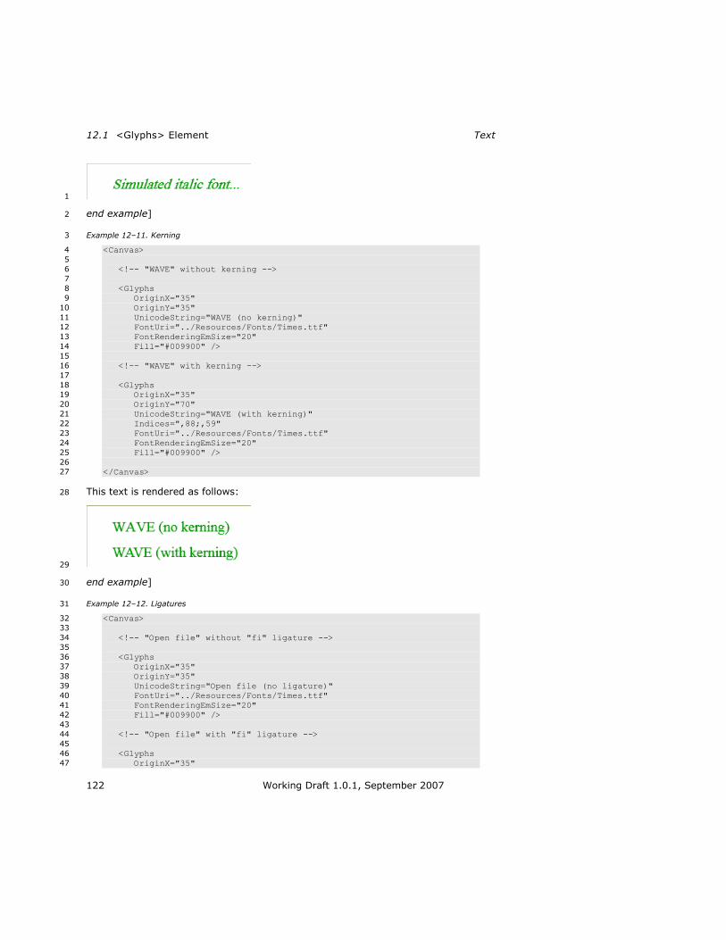
12.1 <Glyphs> Element Text
122 Working Draft 1.0.1, September 2007
1
end example] 2
Example 12–11. Kerning 3
<Canvas> 4
5
<!-- "WAVE" without kerning --> 6
7
<Glyphs 8
OriginX="35" 9
OriginY="35" 10
UnicodeString="WAVE (no kerning)" 11
FontUri="../Resources/Fonts/Times.ttf" 12
FontRenderingEmSize="20" 13
Fill="#009900" /> 14
15
<!-- "WAVE" with kerning --> 16
17
<Glyphs 18
OriginX="35" 19
OriginY="70" 20
UnicodeString="WAVE (with kerning)" 21
Indices=",88;,59" 22
FontUri="../Resources/Fonts/Times.ttf" 23
FontRenderingEmSize="20" 24
Fill="#009900" /> 25
26
</Canvas> 27
This text is rendered as follows: 28
29
end example] 30
Example 12–12. Ligatures 31
<Canvas> 32
33
<!-- "Open file" without "fi" ligature --> 34
35
<Glyphs 36
OriginX="35" 37
OriginY="35" 38
UnicodeString="Open file (no ligature)" 39
FontUri="../Resources/Fonts/Times.ttf" 40
FontRenderingEmSize="20" 41
Fill="#009900" /> 42
43
<!-- "Open file" with "fi" ligature --> 44
45
<Glyphs 46
OriginX="35" 47
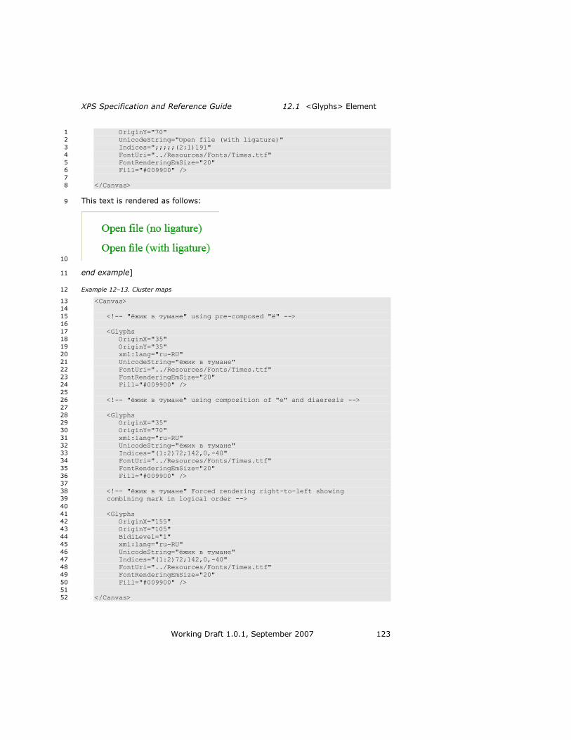
XPS Specification and Reference Guide 12.1 <Glyphs> Element
Working Draft 1.0.1, September 2007 123
OriginY="70" 1
UnicodeString="Open file (with ligature)" 2
Indices=";;;;;(2:1)191" 3
FontUri="../Resources/Fonts/Times.ttf" 4
FontRenderingEmSize="20" 5
Fill="#009900" /> 6
7
</Canvas> 8
This text is rendered as follows: 9
10
end example] 11
Example 12–13. Cluster maps 12
<Canvas> 13
14
<!-- "ёжик в тумане" using pre-composed "ё" --> 15
16
<Glyphs 17
OriginX="35" 18
OriginY="35" 19
xml:lang="ru-RU" 20
UnicodeString="ёжик в тумане" 21
FontUri="../Resources/Fonts/Times.ttf" 22
FontRenderingEmSize="20" 23
Fill="#009900" /> 24
25
<!-- "ёжик в тумане" using composition of "e" and diaeresis --> 26
27
<Glyphs 28
OriginX="35" 29
OriginY="70" 30
xml:lang="ru-RU" 31
UnicodeString="ёжик в тумане" 32
Indices="(1:2)72;142,0,-40" 33
FontUri="../Resources/Fonts/Times.ttf" 34
FontRenderingEmSize="20" 35
Fill="#009900" /> 36
37
<!-- "ёжик в тумане" Forced rendering right-to-left showing 38
combining mark in logical order --> 39
40
<Glyphs 41
OriginX="155" 42
OriginY="105" 43
BidiLevel="1" 44
xml:lang="ru-RU" 45
UnicodeString="ёжик в тумане" 46
Indices="(1:2)72;142,0,-40" 47
FontUri="../Resources/Fonts/Times.ttf" 48
FontRenderingEmSize="20" 49
Fill="#009900" /> 50
51
</Canvas> 52

12.2 <Glyphs.Fill> Element Text
124 Working Draft 1.0.1, September 2007
This text is rendered as follows: 1
2
end example] 3
12.2 <Glyphs.Fill> Element 4
element Glyphs.Fill 5
diagram
annotation Describes the brush used to fill the shape of the rendered glyphs.
The Fill property specifies the brush that fills a glyph. Any brush may be used. 6
7

XPS Specification and Reference Guide 12.2 <Glyphs.Fill> Element
Working Draft 1.0.1, September 2007 125
13. Brushes 1
Brushes are used to paint the interior of the geometric shapes defined by a <Path> 2
element and the characters rendered with a <Glyphs> element. They are also used 3
to define the alpha-transparency mask in the <Canvas.OpacityMask>, 4
<Path.OpacityMask>, and <Glyphs.OpacityMask> property elements. 5
All brushes are defined relative to a coordinate space. Most brushes (including image 6
brushes, visual brushes, linear gradient brushes, and radial gradient brushes) may 7
specify a coordinate-space transform, in which the Transform property is 8
concatenated with the current effective coordinate space to yield an effective 9
coordinate space local to the brush. For image brushes and visual brushes, the 10
viewport is transformed using the local effective render transform. For linear gradient 11
brushes, the start point and end point are transformed. For radial gradient brushes, 12
the ellipse defined by the center, x radius, y radius, and gradient origin is 13
transformed. 14
Table 13–1. Brush types 15
Name Description
Solid color brush Fills a region with a solid color
Image brush Fills a region with an image
Visual brush Fills a region with a drawing
Linear gradient brush Fills a region with a linear gradient
Radial gradient brush Fills a region with a radial gradient

13.1 <SolidColorBrush> Element Brushes
126 Working Draft 1.0.1, September 2007
13.1 <SolidColorBrush> Element 1
element SolidColorBrush 2
diagram
attributes Name Type Use Default Fixed Annotation
Opacity ST_ZeroOne 1.0 Defines the uniform transparency of the brush
fill. Values range from 0 (fully transparent) to
1 (fully opaque), inclusive. Values outside of
this range are invalid.
x:Key Specifies a name for a resource in a resource
dictionary. x:Key MUST be present when the
current element is defined in a resource
dictionary. x:Key MUST NOT be specified
outside of a resource dictionary [M6.1].
Color ST_Color required Specifies the color for filled elements. An sRGB
color value specified as a 6-digit hexadecimal
number (#RRGGBB) or an extended color.
annotation Fills defined geometric regions with a solid color.
The <SolidColorBrush> element is used to fill defined geometric regions with a solid 3
color. If there is an alpha component of the color, it is combined in a multiplicative 4
way with the corresponding Opacity attribute. 5

XPS Specification and Reference Guide 13.2 <ImageBrush> Element
Working Draft 1.0.1, September 2007 127
Example 13–1. <SolidColorBrush> usage 1
The following markup illustrates how a solid color brush fills a path. 2
<Path Stroke="#000000"> 3
<Path.Fill> 4
<SolidColorBrush Color="#00FFFF" /> 5
</Path.Fill> 6
<Path.Data> 7
<PathGeometry> 8
<PathFigure StartPoint="20,20" IsClosed="true"> 9
<PolyLineSegment Points="250,20 135,150" /> 10
</PathFigure> 11
</PathGeometry> 12
</Path.Data> 13
</Path> 14
This markup is rendered as follows: 15
16
end example] 17
13.2 <ImageBrush> Element 18
element ImageBrush 19

13.2 <ImageBrush> Element Brushes
128 Working Draft 1.0.1, September 2007
diagram
attributes Name Type Use Default Fixed Annotation
Opacity ST_ZeroOne 1.0 Defines the uniform transparency
of the brush fill. Values range
from 0 (fully transparent) to 1
(fully opaque), inclusive. Values
outside of this range are invalid.
x:Key Specifies a name for a resource
in a resource dictionary. x:Key
MUST be present when the
current element is defined in a
resource dictionary. x:Key MUST
NOT be specified outside of a
resource dictionary [M6.2].
Transform ST_RscRefMatrix Describes the matrix
transformation applied to the
coordinate space of the brush.
The Transform property is
concatenated with the current
effective render transform to
yield an effective render
transform local to the brush. The
viewport for the brush is
transformed using the local
effective render transform.
Viewbox ST_ViewBox required Specifies the position and
dimensions of the brush's source
content. Specifies four comma-

XPS Specification and Reference Guide 13.2 <ImageBrush> Element
Working Draft 1.0.1, September 2007 129
separated real numbers (x, y,
Width, Height), where width and
height are non-negative. The
dimensions specified are relative
to the image‘s physical
dimensions expressed in units of
1/96". The corners of the
viewbox are mapped to the
corners of the viewport, thereby
providing the default clipping and
transform for the brush‘s source
content.
Viewport ST_ViewBox required Specifies the region in the
containing coordinate space of
the prime brush tile that is
(possibly repeatedly) applied to
fill the region to which the brush
is applied. Specifies four comma-
separated real numbers (x, y,
Width, Height), where width and
height are non-negative. The
alignment of the brush pattern is
controlled by adjusting the x and
y values.
TileMode ST_TileMode None Specifies how contents will be
tiled in the filled region. Valid
values are None, Tile, FlipX,
FlipY, and FlipXY.
ViewboxUnits ST_ViewUnits required Absolute Specifies the relationship of the
viewbox coordinates to the
containing coordinate space.
ViewportUnits ST_ViewUnits required Absolute Specifies the relationship of the
viewport coordinates to the
containing coordinate space.
ImageSource ST_UriCtxBmp required Specifies the URI of an image
resource or a combination of the
URI of an image resource a color
profile resource. See the Color
clause for important details. The
URI MUST refer to parts in the
package [M2.1].
annotation Fills a region with an image.
The <ImageBrush> element is used to fill a region with an image. The image is 1
defined in a coordinate space specified by the resolution of the image. The image 2
MUST refer to a JPEG, PNG, TIFF 6.0, or Windows Media Photo image part within the 3

13.2 <ImageBrush> Element Brushes
130 Working Draft 1.0.1, September 2007
XPS Document package [M6.3]. For more information, see §9.1.5, ―Image Parts,‖ on 1
page 24. A URI part name for the image is specified using the ImageSource 2
attribute. 3
Image brushes share a number of tile-related properties with visual brushes. For 4
details, see §13.4, ―Common Attributes for Tiling Brushes,‖ on page 136. 5
Example 13–2. <ImageBrush> usage 6
The following markup describes an image on a canvas. 7
<Canvas> 8
<Path Stroke="#008000"> 9
<Path.Fill> 10
<ImageBrush 11
ImageSource="dog.jpg" 12
TileMode="None" 13
Viewbox="0,0,270,423" 14
ViewboxUnits="Absolute" 15
Viewport="25,25,125,185" 16
ViewportUnits="Absolute" /> 17
</Path.Fill> 18
<Path.Data> 19
<PathGeometry> 20
<PathFigure StartPoint="25,25" IsClosed="true"> 21
<PolyLineSegment Points="150,25 150,210 25,210" /> 22
</PathFigure> 23
</PathGeometry> 24
</Path.Data> 25
</Path> 26
</Canvas> 27
This markup produces the following results: 28
29
end example] 30

XPS Specification and Reference Guide 13.3 <VisualBrush> Element
Working Draft 1.0.1, September 2007 131
13.3 <VisualBrush> Element 1
element VisualBrush 2
diagram
attributes Name Type Use Default Fixed Annotation
Opacity ST_ZeroOne 1.0 Defines the uniform transparency
of the brush fill. Values range
from 0 (fully transparent) to 1
(fully opaque), inclusive. Values
outside of this range are invalid.
x:Key Specifies a name for a resource
in a resource dictionary. x:Key
MUST be present when the
current element is defined in a
resource dictionary. x:Key MUST
NOT be specified outside of a
resource dictionary [M6.4].
Transform ST_RscRefMatrix Describes the matrix
transformation applied to the
coordinate space of the brush.
The Transform property is
concatenated with the current
effective render transform to
yield an effective render
transform local to the brush. The
viewport for the brush is

13.3 <VisualBrush> Element Brushes
132 Working Draft 1.0.1, September 2007
transformed using that local
effective render transform.
Viewbox ST_ViewBox required Specifies the position and
dimensions of the brush's source
content. Specifies four comma-
separated real numbers (x, y,
Width, Height), where width and
height are non-negative. The
viewbox defines the default
coordinate system for the
element specified in the
<VisualBrush.Visual> property
element. The corners of the
viewbox are mapped to the
corners of the viewport, thereby
providing the default clipping and
transform for the brush‘s source
content.
Viewport ST_ViewBox required Specifies the region in the
containing coordinate space of
the prime brush tile that is
(possibly repeatedly) applied to
fill the region to which the brush
is applied. Specifies four comma-
separated real numbers (x, y,
Width, Height), where width and
height are non-negative. The
alignment of the brush pattern is
controlled by adjusting the x and
y values.
TileMode ST_TileMode None Specifies how contents will be
tiled in the filled region. Valid
values are None, Tile, FlipX,
FlipY, and FlipXY.
ViewboxUnits ST_ViewUnits required Absolute Specifies the relationship of the
viewbox coordinates to the
containing coordinate space.
ViewportUnits ST_ViewUnits required Absolute Specifies the relationship of the
viewport coordinates to the
containing coordinate space.
Visual ST_RscRef Specifies resource reference to a
<Path>, <Glyphs>, or
<Canvas> element defined in a
resource dictionary and used to
draw the brush‘s source content.

XPS Specification and Reference Guide 13.3 <VisualBrush> Element
Working Draft 1.0.1, September 2007 133
annotation Fills a region with a drawing. The drawing may be specified as either a child of the <VisualBrush>
element, or as a resource reference. Drawing content is expressed using <Canvas>, <Path>, and
<Glyphs> elements.
The <VisualBrush> element is used to fill a region with a drawing. The drawing may 1
be specified as either a <VisualBrush.Visual> property element or as a resource 2
reference. Drawing content may include exactly one <Canvas>, <Path>, or 3
<Glyphs> element and that element‘s child and descendant elements. 4
Visual brushes share a number of tile-related properties with image brushes. For 5
details, see §13.4, ―Common Attributes for Tiling Brushes,‖ on page 136. 6
13.3.1 <VisualBrush.Visual> Element 7
element VisualBrush.Visual 8
diagram
annotation Specifies a <Path> element, <Glyphs> element, or <Canvas> element used to draw the brush‘s
source contents.
The <VisualBrush.Visual> property element contains markup that defines the 9
contents of a single visual brush tile. The tile can be used to fill the geometric region 10
to which the visual brush is applied. The <VisualBrush.Visual> property element 11
contains a single child element. For simple tiles, this can be a single <Path> or 12
<Glyphs> element. More complex visuals containing multiple <Path> and <Glyphs> 13
elements can be grouped within a <Canvas> child element. 14

13.3 <VisualBrush> Element Brushes
134 Working Draft 1.0.1, September 2007
Example 13–3. <VisualBrush.Visual> usage 1
<Path> 2
<Path.Fill> 3
<VisualBrush 4
Viewbox="0,0,1,1" 5
Viewport="50,50,100,100" 6
ViewportUnits="Absolute" 7
ViewboxUnits="Absolute" 8
TileMode="Tile"> 9
<VisualBrush.Visual> 10
<Path> 11
<Path.Fill> 12
<SolidColorBrush Color="#FF0000" /> 13
</Path.Fill> 14
<Path.Data> 15
<PathGeometry> 16
<PathFigure StartPoint="0,0.5" IsClosed="true"> 17
<PolyLineSegment Points="0.5,0 1.0,0.5 18
0.5,1.0" /> 19
</PathFigure> 20
</PathGeometry> 21
</Path.Data> 22
</Path> 23
</VisualBrush.Visual> 24
</VisualBrush> 25
</Path.Fill> 26
<Path.Data> 27
<PathGeometry> 28
<PathFigure StartPoint="50,50" IsClosed="true"> 29
<PolyLineSegment Points="350,50 350,350 50,350" /> 30
</PathFigure> 31
</PathGeometry> 32
</Path.Data> 33
</Path> 34

XPS Specification and Reference Guide 13.3 <VisualBrush> Element
Working Draft 1.0.1, September 2007 135
This markup produces the following result: 1
2
end example] 3

13.4 Common Attributes for Tiling Brushes Brushes
136 Working Draft 1.0.1, September 2007
13.4 Common Attributes for Tiling Brushes 1
Image brushes and Visual brushes share certain tiling characteristics in common. 2
These characteristics are controlled by a common set of attributes described in the 3
table below. 4
Table 13–2. Common attributes for <ImageBrush> and <VisualBrush> elements 5
Name Description
Viewbox Specifies the region of the source content of the brush that is to be mapped to the viewport.
Viewport Specifies the position and dimensions of the first brush tile. Subsequent tiles are positioned relative to this tile, as specified by the tile mode.
ViewboxUnits Specifies the unit type for the Viewbox attribute. MUST have the value ―Absolute‖ [M2.72].
ViewportUnits Specifies the unit type for the Viewport attribute. MUST have the
value ―Absolute‖ [M2.72].
TileMode Specifies how tiling is performed in the filled geometry. The value is optional, and defaults to ―None‖ if no value is specified.
Both image brushes and visual brushes assume that the background of the brush 6
itself is initially transparent. 7
13.4.1 Viewbox, Viewport, ViewboxUnits, and ViewportUnits Attributes 8
The Viewbox attribute specifies the portion of a source image or visual to be 9
rendered to the page as a tile. The Viewport attribute specifies the dimensions and 10
location, in the effective coordinate space, of the initial tile that will be filled with the 11
specified image or visual fragment. In other words, the Viewport attribute defines 12
the initial tile whose origin (x and y values of the top left corner of the tile relative to 13
the current effective render transform) is specified by the first two parameters and 14
whose size (width and height values) is specified by the last two parameters. The tile 15
is then used to fill the geometry specified by the parent element according to the 16
TileMode attribute relative to the initial tile. 17
For images, the dimensions specified by the viewbox are expressed in units of 1/96". 18
The pixel coordinates in the source image are calculated as follows: 19
SourceLeft = HorizontalImageResolution * Viewbox.Left / 96 20
SourceTop = VerticalImageResolution * Viewbox.Top / 96 21
SourceWidth = HorizontalImageResolution * Viewbox.Width / 96 22
SourceHeight = VerticalImageResolution * Viewbox.Height / 96 23
The image resolution used is that specified in the header or tag information of the 24
image. If no resolution is specified, a default resolution of 96 dpi is assumed. The 25
coordinates of the upper-left corner of the image are 0,0. 26
The viewbox can specify a region larger than the image itself, including negative 27
values. 28

XPS Specification and Reference Guide13.4 Common Attributes for Tiling Brushes
Working Draft 1.0.1, September 2007 137
Example 13–4. ViewboxUnits and ViewportUnits attribute usage 1
The following markup contains an image brush: 2
<ImageBrush 3
ImageSource="../Resources/Images/tiger.jpg" 4
Viewbox="24,24,48,48" 5
ViewboxUnits="Absolute" 6
Viewport="96,96,192,192" 7
ViewportUnits="Absolute" 8
TileMode="None" /> 9
Assuming the default fixed page coordinate system and that tiger.jpg specifies a 10
resolution of 50 dpi and measures 100 pixels horizontally and 50 pixels vertically, the 11
physical dimensions of the image are expressed (in units of 1/96") as 96 * 100 / 50 12
= 192 horizontal and 96 * 50 / 50 = 96 vertical. 13
The viewbox uses a square starting at 24,24 (a quarter-inch from left and a quarter-14
inch from top) in the image, and extending for 48,48 (a half-inch to the right and a 15
half-inch down) and scales it to a square starting at one inch from the left edge of 16
the physical page and one inch from the top of the physical page and extending two 17
inches to the right and two inches down. end example] 18
13.4.1.1 Viewbox and Viewport Examples 19
The following examples demonstrate how adjusting the viewbox and viewport can 20
affect output. 21
Example 13–5. Tiling brush base image and rendering 22
The following markup describes a base image. 23
<!-- Draw background diamond to show where fill affects background --> 24
<Path Fill="#CCCC66" Data="M 150,0 L 300,150 L 150,300 L 0,150 Z" /> 25
<Path Data="M 150,0 L 300,150 L 150,300 L 0,150 Z"> 26
<Path.Fill> 27
<VisualBrush 28
Viewbox="0,0,1,1" 29
Viewport="150,75,50,50" 30
ViewboxUnits="Absolute" 31
ViewportUnits="Absolute" 32
TileMode="Tile"> 33
<VisualBrush.Visual> 34
<Canvas> 35
<Path Fill="#333399" Data="M 0.1,0.1 L 0.9,0.1 L 0.9,0.9 36
L 0.1,0.9 Z" /> 37
<Path Fill="#FFFF00" Data="M 0.1,0.35 L 0.35,0.1 38
L 0.6,0.35 L 0.35,0.6 Z" /> 39
</Canvas> 40
</VisualBrush.Visual> 41
</VisualBrush> 42
</Path.Fill> 43
</Path> 44

13.4 Common Attributes for Tiling Brushes Brushes
138 Working Draft 1.0.1, September 2007
This markup is rendered as follows: 1
2
end example] 3
Example 13–6. Tiling brush Viewport adjustments 4
By adjusting the viewport, the position of the tiles within the image can be changed: 5
<!-- Draw background diamond to show where fill affects background --> 6
<Path Fill="#CCCC66" Data="M 150,0 L 300,150 L 150,300 L 0,150 Z" /> 7
<Path Data="M 150,0 L 300,150 L 150,300 L 0,150 Z"> 8
<Path.Fill> 9
<VisualBrush 10
Viewbox="0,0,1,1" 11
Viewport="125,125,50,50" 12
ViewboxUnits="Absolute" 13
ViewportUnits="Absolute" 14
TileMode="Tile"> 15
<VisualBrush.Visual> 16
<Canvas> 17
<Path Fill="#333399" Data="M 0.1,0.1 L 0.9,0.1 L 0.9,0.9 18
L 0.1,0.9 Z" /> 19
<Path Fill="#FFFF00" Data="M 0.1,0.35 L 0.35,0.1 20
L 0.6,0.35 L 0.35,0.6 Z" /> 21
</Canvas> 22
</VisualBrush.Visual> 23
</VisualBrush> 24
</Path.Fill> 25
</Path> 26

XPS Specification and Reference Guide13.4 Common Attributes for Tiling Brushes
Working Draft 1.0.1, September 2007 139
This markup is rendered as follows: 1
2
end example] 3
Example 13–7. Tiling brush viewbox adjustments 4
The following markup uses a smaller window on the viewbox to zoom in on each tile: 5
<!-- Draw background diamond to show where fill affects background --> 6
<Path Fill="#CCCC66" Data="M 150,0 L 300,150 L 150,300 L 0,150 Z" /> 7
<Path Data="M 150,0 L 300,150 L 150,300 L 0,150 Z"> 8
<Path.Fill> 9
<VisualBrush 10
Viewbox="0.25,0.25,0.75,0.75" 11
Viewport="150,75,50,50" 12
ViewboxUnits="Absolute" 13
ViewportUnits="Absolute" 14
TileMode="Tile"> 15
<VisualBrush.Visual> 16
<Canvas> 17
<Path Fill="#333399" Data="M 0.1,0.1 L 0.9,0.1 L 0.9,0.9 18
L 0.1,0.9 Z" /> 19
<Path Fill="#FFFF00" Data="M 0.1,0.35 L 0.35,0.1 20
L 0.6,0.35 L 0.35,0.6 Z" /> 21
</Canvas> 22
</VisualBrush.Visual> 23
</VisualBrush> 24
</Path.Fill> 25
</Path> 26

13.4 Common Attributes for Tiling Brushes Brushes
140 Working Draft 1.0.1, September 2007
This markup is rendered as follows: 1
2
end example] 3
Example 13–8. Image brush with a Viewbox larger than the image 4
An image brush can specify a tile with the Viewbox attribute that exceeds the size 5
of the image it uses, including negative values, as shown below. 6
<Path Fill="#CCCCCC" Data="M 10,10 L 265,10 L 265,125 L 10,125 Z" /> 7
<Path Stroke="#803333" StrokeThickness="3" 8
Data="M 25,25 L 250,25 L 250,200 L 25,200 Z"> 9
<Path.Fill> 10
<ImageBrush ImageSource="../Resources/Images/dog.jpg" 11
TileMode="Tile" 12
Viewbox="-10,-10,290,443" ViewboxUnits="Absolute" 13
Viewport="50,50,90,125" ViewportUnits="Absolute" /> 14
</Path.Fill> 15
</Path> 16
This markup is rendered as follows. Note that the area around the image is 17
transparent, revealing the underlying path between the tiles. 18
19

XPS Specification and Reference Guide13.4 Common Attributes for Tiling Brushes
Working Draft 1.0.1, September 2007 141
end example] 1
13.4.2 TileMode Attribute 2
Valid values for the TileMode attribute are None, Tile, FlipX, FlipY, and FlipXY. 3
13.4.2.1 None 4
In this mode, only the single base tile is drawn. The remaining area is left 5
transparent. 6
Example 13–9. Image brush with TileMode value of None 7
<!-- Draw background diamond to show where fill affects background --> 8
<Path Fill="#CCCC66" Data="M 200,0 L 400,200 L 200,400 L 0,200 Z" /> 9
<Path Data="M 200,0 L 400,200 L 200,400 L 0,200 Z"> 10
<Path.Fill> 11
<ImageBrush 12
ImageSource="newspaper.png" 13
Viewbox="0,0,350,284" 14
Viewport="200,100,87,71" 15
ViewportUnits="Absolute" 16
ViewboxUnits="Absolute" 17
TileMode="None" /> 18
</Path.Fill> 19
</Path> 20
This markup is rendered as follows: 21
22
end example] 23
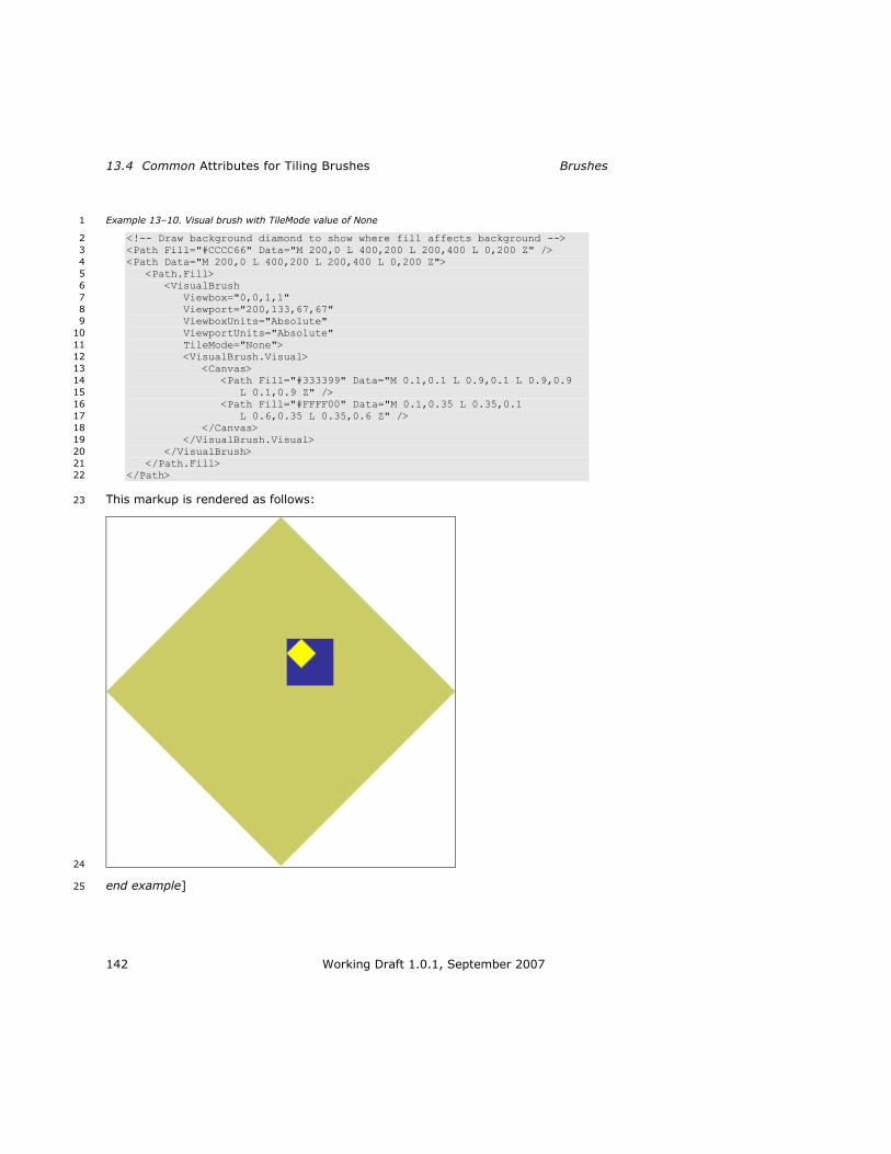
13.4 Common Attributes for Tiling Brushes Brushes
142 Working Draft 1.0.1, September 2007
Example 13–10. Visual brush with TileMode value of None 1
<!-- Draw background diamond to show where fill affects background --> 2
<Path Fill="#CCCC66" Data="M 200,0 L 400,200 L 200,400 L 0,200 Z" /> 3
<Path Data="M 200,0 L 400,200 L 200,400 L 0,200 Z"> 4
<Path.Fill> 5
<VisualBrush 6
Viewbox="0,0,1,1" 7
Viewport="200,133,67,67" 8
ViewboxUnits="Absolute" 9
ViewportUnits="Absolute" 10
TileMode="None"> 11
<VisualBrush.Visual> 12
<Canvas> 13
<Path Fill="#333399" Data="M 0.1,0.1 L 0.9,0.1 L 0.9,0.9 14
L 0.1,0.9 Z" /> 15
<Path Fill="#FFFF00" Data="M 0.1,0.35 L 0.35,0.1 16
L 0.6,0.35 L 0.35,0.6 Z" /> 17
</Canvas> 18
</VisualBrush.Visual> 19
</VisualBrush> 20
</Path.Fill> 21
</Path> 22
This markup is rendered as follows: 23
24
end example] 25

XPS Specification and Reference Guide13.4 Common Attributes for Tiling Brushes
Working Draft 1.0.1, September 2007 143
13.4.2.2 Tile 1
In this mode, the base tile is drawn and the remaining area is filled by repeating the 2
base tile such that the right edge of each tile abuts the left edge of the next, and the 3
bottom edge of each tile abuts the top edge of the next. 4
Example 13–11. Image brush with a TileMode value of Tile 5
<!-- Draw background diamond to show where fill affects background --> 6
<Path Fill="#CCCC66" Data="M 200,0 L 400,200 L 200,400 L 0,200 Z" /> 7
<Path Data="M 200,0 L 400,200 L 200,400 L 0,200 Z"> 8
<Path.Fill> 9
<ImageBrush 10
ImageSource="newspaper.png" 11
Viewbox="0,0,350,284" 12
Viewport="200,100,87,71" 13
ViewportUnits="Absolute" 14
ViewboxUnits="Absolute" 15
TileMode="Tile" /> 16
</Path.Fill> 17
</Path> 18
This markup is rendered as follows: 19
20
end example] 21

13.4 Common Attributes for Tiling Brushes Brushes
144 Working Draft 1.0.1, September 2007
Example 13–12. Visual brush with a TileMode value of Tile 1
<!-- Draw background diamond to show where fill affects background --> 2
<Path Fill="#CCCC66" Data="M 200,0 L 400,200 L 200,400 L 0,200 Z" /> 3
<Path Data="M 200,0 L 400,200 L 200,400 L 0,200 Z"> 4
<Path.Fill> 5
<VisualBrush 6
Viewbox="0,0,1,1" 7
Viewport="200,133,67,67" 8
ViewboxUnits="Absolute" 9
ViewportUnits="Absolute" 10
TileMode="Tile"> 11
<VisualBrush.Visual> 12
<Canvas> 13
<Path Fill="#333399" Data="M 0.1,0.1 L 0.9,0.1 L 0.9,0.9 14
L 0.1,0.9 Z" /> 15
<Path Fill="#FFFF00" Data="M 0.1,0.35 L 0.35,0.1 16
L 0.6,0.35 L 0.35,0.6 Z" /> 17
</Canvas> 18
</VisualBrush.Visual> 19
</VisualBrush> 20
</Path.Fill> 21
</Path> 22
This markup is rendered as follows: 23
24
end example] 25

XPS Specification and Reference Guide13.4 Common Attributes for Tiling Brushes
Working Draft 1.0.1, September 2007 145
13.4.2.3 FlipX 1
The tile arrangement is similar to the Tile tile mode, but alternate columns of tiles 2
are flipped horizontally. The base tile is positioned as specified by the viewport. Tiles 3
in the columns to the left and right of this tile are flipped horizontally. 4
Example 13–13. Image brush with a TileMode value of FlipX 5
<!-- Draw background diamond to show where fill affects background --> 6
<Path Fill="#CCCC66" Data="M 200,0 L 400,200 L 200,400 L 0,200 Z" /> 7
<Path Data="M 200,0 L 400,200 L 200,400 L 0,200 Z"> 8
<Path.Fill> 9
<ImageBrush 10
ImageSource="newspaper.png" 11
Viewbox="0,0,350,284" 12
Viewport="200,100,87,71" 13
ViewportUnits="Absolute" 14
ViewboxUnits="Absolute" 15
TileMode="FlipX" /> 16
</Path.Fill> 17
</Path> 18
This markup is rendered as follows: 19
20
end example] 21

13.4 Common Attributes for Tiling Brushes Brushes
146 Working Draft 1.0.1, September 2007
Example 13–14. Visual brush with a TileMode value of FlipX 1
<!-- Draw background diamond to show where fill affects background --> 2
<Path Fill="#CCCC66" Data="M 200,0 L 400,200 L 200,400 L 0,200 Z" /> 3
<Path Data="M 200,0 L 400,200 L 200,400 L 0,200 Z"> 4
<Path.Fill> 5
<VisualBrush 6
Viewbox="0,0,1,1" 7
Viewport="200,133,67,67" 8
ViewboxUnits="Absolute" 9
ViewportUnits="Absolute" 10
TileMode="FlipX"> 11
<VisualBrush.Visual> 12
<Canvas> 13
<Path Fill="#333399" Data="M 0.1,0.1 L 0.9,0.1 L 0.9,0.9 14
L 0.1,0.9 Z" /> 15
<Path Fill="#FFFF00" Data="M 0.1,0.35 L 0.35,0.1 16
L 0.6,0.35 L 0.35,0.6 Z" /> 17
</Canvas> 18
</VisualBrush.Visual> 19
</VisualBrush> 20
</Path.Fill> 21
</Path> 22
This markup is rendered as follows: 23
24
end example] 25
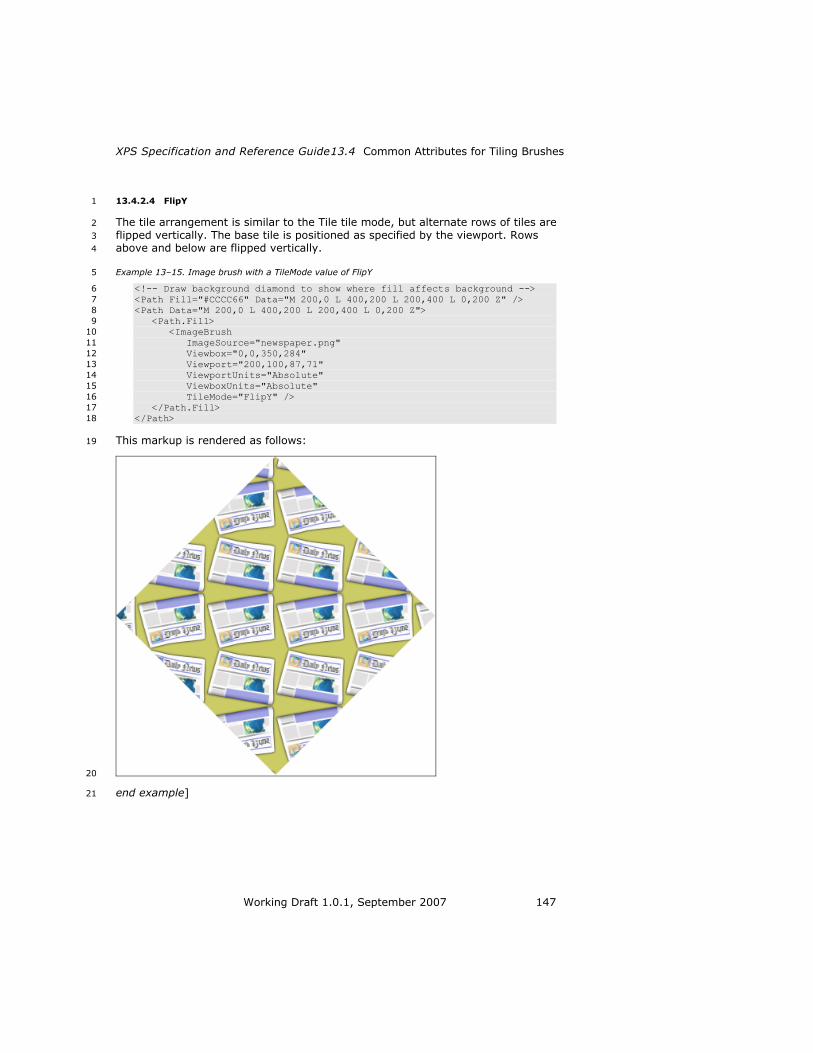
XPS Specification and Reference Guide13.4 Common Attributes for Tiling Brushes
Working Draft 1.0.1, September 2007 147
13.4.2.4 FlipY 1
The tile arrangement is similar to the Tile tile mode, but alternate rows of tiles are 2
flipped vertically. The base tile is positioned as specified by the viewport. Rows 3
above and below are flipped vertically. 4
Example 13–15. Image brush with a TileMode value of FlipY 5
<!-- Draw background diamond to show where fill affects background --> 6
<Path Fill="#CCCC66" Data="M 200,0 L 400,200 L 200,400 L 0,200 Z" /> 7
<Path Data="M 200,0 L 400,200 L 200,400 L 0,200 Z"> 8
<Path.Fill> 9
<ImageBrush 10
ImageSource="newspaper.png" 11
Viewbox="0,0,350,284" 12
Viewport="200,100,87,71" 13
ViewportUnits="Absolute" 14
ViewboxUnits="Absolute" 15
TileMode="FlipY" /> 16
</Path.Fill> 17
</Path> 18
This markup is rendered as follows: 19
20
end example] 21

13.4 Common Attributes for Tiling Brushes Brushes
148 Working Draft 1.0.1, September 2007
Example 13–16. Visual Brush with a TileMode value of FlipY 1
<!-- Draw background diamond to show where fill affects background --> 2
<Path Fill="#CCCC66" Data="M 200,0 L 400,200 L 200,400 L 0,200 Z" /> 3
<Path Data="M 200,0 L 400,200 L 200,400 L 0,200 Z"> 4
<Path.Fill> 5
<VisualBrush 6
Viewbox="0,0,1,1" 7
Viewport="200,133,67,67" 8
ViewboxUnits="Absolute" 9
ViewportUnits="Absolute" 10
TileMode="FlipY"> 11
<VisualBrush.Visual> 12
<Canvas> 13
<Path Fill="#333399" Data="M 0.1,0.1 L 0.9,0.1 L 0.9,0.9 14
L 0.1,0.9 Z" /> 15
<Path Fill="#FFFF00" Data="M 0.1,0.35 L 0.35,0.1 16
L 0.6,0.35 L 0.35,0.6 Z" /> 17
</Canvas> 18
</VisualBrush.Visual> 19
</VisualBrush> 20
</Path.Fill> 21
</Path> 22
This markup is rendered as follows: 23
24
end example] 25
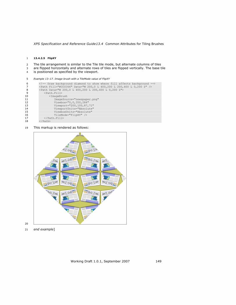
XPS Specification and Reference Guide13.4 Common Attributes for Tiling Brushes
Working Draft 1.0.1, September 2007 149
13.4.2.5 FlipXY 1
The tile arrangement is similar to the Tile tile mode, but alternate columns of tiles 2
are flipped horizontally and alternate rows of tiles are flipped vertically. The base tile 3
is positioned as specified by the viewport. 4
Example 13–17. Image brush with a TileMode value of FlipXY 5
<!-- Draw background diamond to show where fill affects background --> 6
<Path Fill="#CCCC66" Data="M 200,0 L 400,200 L 200,400 L 0,200 Z" /> 7
<Path Data="M 200,0 L 400,200 L 200,400 L 0,200 Z"> 8
<Path.Fill> 9
<ImageBrush 10
ImageSource="newspaper.png" 11
Viewbox="0,0,350,284" 12
Viewport="200,100,87,71" 13
ViewportUnits="Absolute" 14
ViewboxUnits="Absolute" 15
TileMode="FlipXY" /> 16
</Path.Fill> 17
</Path> 18
This markup is rendered as follows: 19
20
end example] 21

13.4 Common Attributes for Tiling Brushes Brushes
150 Working Draft 1.0.1, September 2007
Example 13–18. Visual brush with a TileMode value of FlipXY 1
<!-- Draw background diamond to show where fill affects background --> 2
<Path Fill="#CCCC66" Data="M 200,0 L 400,200 L 200,400 L 0,200 Z" /> 3
<Path Data="M 200,0 L 400,200 L 200,400 L 0,200 Z"> 4
<Path.Fill> 5
<VisualBrush 6
Viewbox="0,0,1,1" 7
Viewport="200,133,67,67" 8
ViewboxUnits="Absolute" 9
ViewportUnits="Absolute" 10
TileMode="FlipXY"> 11
<VisualBrush.Visual> 12
<Canvas> 13
<Path Fill="#333399" Data="M 0.1,0.1 L 0.9,0.1 L 0.9,0.9 14
L 0.1,0.9 Z" /> 15
<Path Fill="#FFFF00" Data="M 0.1,0.35 L 0.35,0.1 16
L 0.6,0.35 L 0.35,0.6 Z" /> 17
</Canvas> 18
</VisualBrush.Visual> 19
</VisualBrush> 20
</Path.Fill> 21
</Path> 22
This markup is rendered as follows: 23
24
end example] 25

XPS Specification and Reference Guide13.5 <LinearGradientBrush> Element
Working Draft 1.0.1, September 2007 151
13.5 <LinearGradientBrush> Element 1
element LinearGradientBrush 2
diagram
attributes Name Type Use Default Fixed Annotation
Opacity ST_ZeroOne 1.0 Defines the uniform
transparency of the
linear gradient. Values
range from 0 (fully
transparent) to 1 (fully
opaque), inclusive.
Values outside of this
range are invalid.
x:Key Specifies a name for a
resource in a resource
dictionary. x:Key MUST
be present when the
current element is
defined in a resource
dictionary. x:Key MUST
NOT be specified
outside of a resource
dictionary [M6.5].
ColorInterpolationMode
ST_ClrIntMode
SRgbLinear
Interpolation
Specifies the gamma
function for color
interpolation. The
gamma adjustment

13.5 <LinearGradientBrush> Element Brushes
152 Working Draft 1.0.1, September 2007
should not be applied to
the alpha component, if
specified. Valid values
are
SRgbLinearInterpolation
and
ScRgbLinearInterpolatio
n.
SpreadMethod ST_Spread
Method Pad Describes how the brush
should fill the content
area outside of the
primary, initial gradient
area. Valid values are
Pad, Reflect and Repeat.
MappingMode ST_Mapping
Mode required
Absolute
Specifies that the start
point and end point are
defined in the effective
coordinate space
(includes the Transform
attribute of the brush).
Transform ST_RscRef
Matrix Describes the matrix
transformation applied
to the coordinate space
of the brush. The
Transform property on a
brush is concatenated
with the current
effective render
transform to yield an
effective render
transform local to the
brush. The start point
and end point are
transformed using the
local effective render
transform.
StartPoint ST_Point required
Specifies the starting
point of the linear
gradient.
EndPoint ST_Point required
Specifies the end point
of the linear gradient.
The linear gradient
brush interpolates the
colors from the start
point to the end point,
where the start point
represents an offset of

XPS Specification and Reference Guide13.5 <LinearGradientBrush> Element
Working Draft 1.0.1, September 2007 153
0, and the EndPoint
represents an offset of
1. The Offset attribute
value specified in a
GradientStop element
relates to the 0 and 1
offsets defined by the
start point and end
point.
annotatio
n Fills a region with a linear gradient.
The <LinearGradientBrush> element is used to specify a linear gradient brush along 1
a vector. For details about computing a linear gradient, see Section18.3, ―Gradient 2
Computations,‖ on page 272. 3
Example 13–19. <LinearGradientBrush> usage 4
The following markup describes a page with a rectangular path that is filled with a 5
linear gradient: 6
<Path> 7
<Path.Fill> 8
<LinearGradientBrush 9
MappingMode="Absolute" 10
StartPoint="0,0" 11
EndPoint="300,300"> 12
<LinearGradientBrush.GradientStops> 13
<GradientStop Color="#FFFF00" Offset="0" /> 14
<GradientStop Color="#0000FF" Offset="1" /> 15
</LinearGradientBrush.GradientStops> 16
</LinearGradientBrush> 17
</Path.Fill> 18
<Path.Data> 19
<PathGeometry> 20
<PathFigure StartPoint="0,0"> 21
<PolyLineSegment Points="300,0 300,300 0,300" /> 22
</PathFigure> 23
</PathGeometry> 24
</Path.Data> 25
</Path> 26

13.5 <LinearGradientBrush> Element Brushes
154 Working Draft 1.0.1, September 2007
This markup is rendered as follows: 1
2
end example] 3
13.5.1 SpreadMethod Attribute 4
The SpreadMethod attribute describes the fill for areas beyond the start point and 5
end point of the linear gradient brush. Valid values are Pad, Reflect, and Repeat. 6
Example 13–20. Linear gradient brush with a SpreadMethod value of Pad 7
In this method, the first color and the last color are used to fill the remaining fill area 8
at the beginning and end. 9
<Path Data="M 150,0 L 300,150 L 150,300 L 0,150 Z"> 10
<Path.Fill> 11
<LinearGradientBrush 12
MappingMode="Absolute" 13
StartPoint="120,0" 14
EndPoint="180,0" 15
SpreadMethod="Pad"> 16
<LinearGradientBrush.GradientStops> 17
<GradientStop Color="#FFFF00" Offset="0.0" /> 18
<GradientStop Color="#0000FF" Offset="1.0" /> 19
</LinearGradientBrush.GradientStops> 20
</LinearGradientBrush> 21
</Path.Fill> 22
</Path> 23

XPS Specification and Reference Guide13.5 <LinearGradientBrush> Element
Working Draft 1.0.1, September 2007 155
This markup is rendered as follows: 1
2
end example] 3
Example 13–21. Linear gradient brush with a SpreadMethod value of Reflect 4
In this method, the gradient stops are replayed in reverse order repeatedly to cover 5
the fill area. 6
<Path Data="M 150,0 L 300,150 L 150,300 L 0,150 Z"> 7
<Path.Fill> 8
<LinearGradientBrush 9
MappingMode="Absolute" 10
StartPoint="120,0" 11
EndPoint="180,0" 12
SpreadMethod="Reflect"> 13
<LinearGradientBrush.GradientStops> 14
<GradientStop Color="#FFFF00" Offset="0.0" /> 15
<GradientStop Color="#0000FF" Offset="1.0" /> 16
</LinearGradientBrush.GradientStops> 17
</LinearGradientBrush> 18
</Path.Fill> 19
</Path> 20
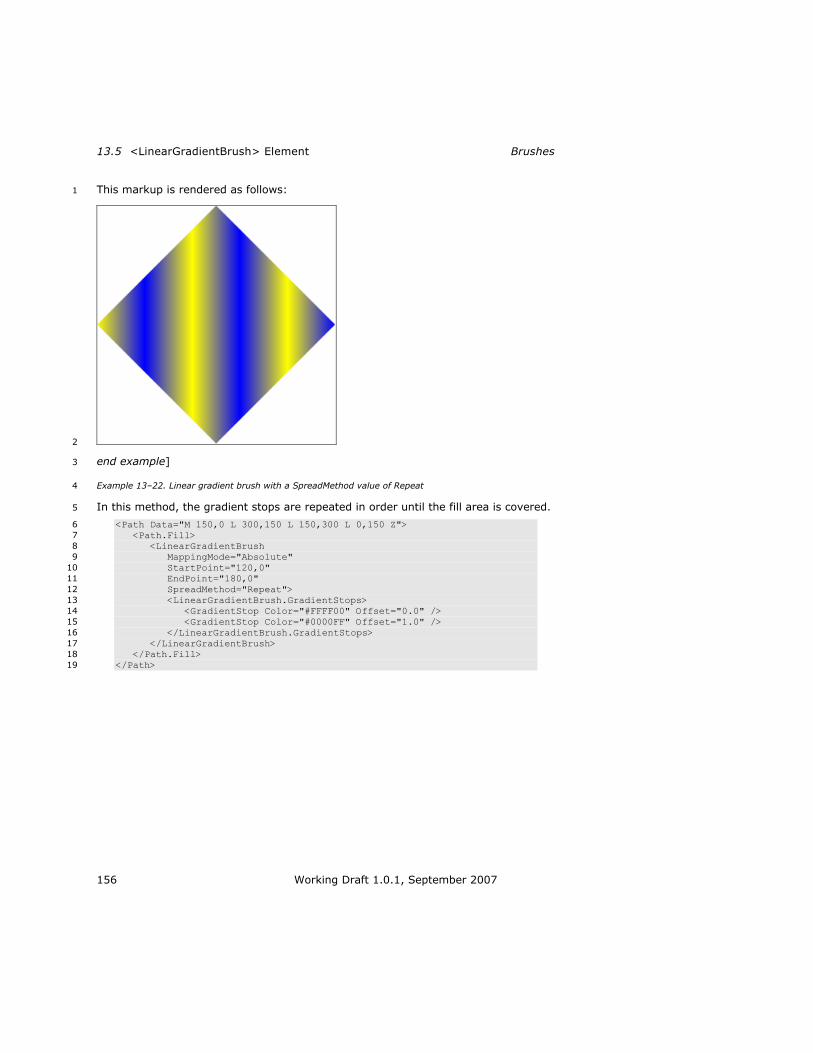
13.5 <LinearGradientBrush> Element Brushes
156 Working Draft 1.0.1, September 2007
This markup is rendered as follows: 1
2
end example] 3
Example 13–22. Linear gradient brush with a SpreadMethod value of Repeat 4
In this method, the gradient stops are repeated in order until the fill area is covered. 5
<Path Data="M 150,0 L 300,150 L 150,300 L 0,150 Z"> 6
<Path.Fill> 7
<LinearGradientBrush 8
MappingMode="Absolute" 9
StartPoint="120,0" 10
EndPoint="180,0" 11
SpreadMethod="Repeat"> 12
<LinearGradientBrush.GradientStops> 13
<GradientStop Color="#FFFF00" Offset="0.0" /> 14
<GradientStop Color="#0000FF" Offset="1.0" /> 15
</LinearGradientBrush.GradientStops> 16
</LinearGradientBrush> 17
</Path.Fill> 18
</Path> 19

XPS Specification and Reference Guide13.5 <LinearGradientBrush> Element
Working Draft 1.0.1, September 2007 157
This markup is rendered as follows: 1
2
end example] 3
13.5.2 <LinearGradientBrush.GradientStops> Element 4
element LinearGradientBrush.GradientStops 5
diagram
annotation Holds a sequence of GradientStop elements.
6
The <LinearGradientBrush.GradientStops> property element specifies a collection of 7
gradient stops that comprise the linear gradient. For more information, see §13.7, 8
―<GradientStop> Element,‖ on page 166. 9

13.6 <RadialGradientBrush> Element Brushes
158 Working Draft 1.0.1, September 2007
13.6 <RadialGradientBrush> Element 1
element RadialGradientBrush 2
diagram
attributes Name Type Use Default Fixed Annotation
Opacity ST_ZeroOne 1.0 Defines the uniform
transparency of the
radial gradient. Values
range from 0 (fully
transparent) to 1 (fully
opaque), inclusive.
Values outside of this
range are invalid.
x:Key Specifies a name for a
resource in a resource
dictionary. x:Key MUST
be present when the
current element is
defined in a resource
dictionary. x:Key MUST
NOT be specified
outside of a resource
dictionary [M6.6].
ColorInterpolationMode ST_ClrIntMode SRgbLinear Specifies the gamma

XPS Specification and Reference Guide13.6 <RadialGradientBrush> Element
Working Draft 1.0.1, September 2007 159
Interpolation
function for color
interpolation for sRGB
colors. The gamma
adjustment should not
be applied to the alpha
component, if specified.
Valid values are
SRgbLinearInterpolation
and
ScRgbLinearInterpolatio
n.
SpreadMethod ST_Spread
Method Pad Describes how the brush
should fill the content
area outside of the
primary, initial gradient
area. Valid values are
Pad, Reflect and Repeat.
MappingMode ST_Mapping
Mode required
Absolute
Specifies that center, x
radius, and y radius are
defined in the effective
coordinate space
(includes the Transform
attribute of the brush).
Transform ST_RscRef
Matrix Describes the matrix
transformation applied
to the coordinate space
of the brush. The
Transform property is
concatenated with the
current effective render
transform to yield an
effective render
transform local to the
brush. The ellipse
defined by the center,
gradient origin, x
radius, and y radius
values is transformed
using the local effective
render transform.
Center ST_Point required
Specifies the center
point of the radial
gradient (that is, the
center of the ellipse).
The radial gradient
brush interpolates the
colors from the gradient
origin to the
circumference of the

13.6 <RadialGradientBrush> Element Brushes
160 Working Draft 1.0.1, September 2007
ellipse. The
circumference is
determined by the
center and the radii.
GradientOrigin ST_Point required
Specifies the origin
point of the radial
gradient.
RadiusX ST_GEZero required
Specifies the radius in
the x dimension of the
ellipse which defines the
radial gradient.
RadiusY ST_GEZero required
Specifies the radius in
the y dimension of the
ellipse which defines the
radial gradient.
annotatio
n Fills a region with a radial gradient.
Radial gradient brushes are similar to linear gradient brushes. However, whereas a 1
linear gradient brush has a start point and end point to define the gradient vector, a 2
radial gradient brush has an ellipse (defined by the center, x radius, and y radius) 3
and a gradient origin. The ellipse defines the end point of the gradient. In other 4
words, a gradient stop with an offset at 1.0 defines the color at the circumference of 5
the ellipse. The gradient origin defines the center of the gradient. A gradient stop 6
with an offset at 0.0 defines the color at the gradient origin. 7
For details about computing a radial gradient, see §18.3.3, ―Radial Gradients,‖ on 8
page 276. 9

XPS Specification and Reference Guide13.6 <RadialGradientBrush> Element
Working Draft 1.0.1, September 2007 161
Example 13–23. A radial gradient brush 1
The following figure is a radial gradient that transitions from white to gray. The 2
outside ellipse represents the gradient ellipse while the dot denotes the gradient 3
origin. This gradient has a SpreadMethod value of Pad. end example] 4
Example 13–24. RadialGradientBrush usage 5
The following markup describes a page with a 6
rectangular path that is filled with a radial 7
gradient: 8
<Path> 9
<Path.Fill> 10
<RadialGradientBrush 11
MappingMode="Absolute" 12
Center="30,150" 13
GradientOrigin="30,150" 14
RadiusX="250" 15
RadiusY="250"> 16
17
<RadialGradientBrush.GradientStops> 18
<GradientStop Color="#FFFF00" 19
Offset="0" /> 20
<GradientStop Color="#0000FF" Offset="1" /> 21
</RadialGradientBrush.GradientStops> 22
</RadialGradientBrush> 23
</Path.Fill> 24
<Path.Data> 25
<PathGeometry> 26
<PathFigure StartPoint="0,0" IsClosed="true"> 27
<PolyLineSegment Points="300,0 300,300 0,300" /> 28
</PathFigure> 29
</PathGeometry> 30
</Path.Data> 31
</Path> 32
This markup is rendered as follows: 33
34

13.6 <RadialGradientBrush> Element Brushes
162 Working Draft 1.0.1, September 2007
end example] 1
13.6.1 SpreadMethod Attribute 2
The SpreadMethod attribute describes the fill of areas beyond the ellipse described 3
by the center, x radius, and y radius of the radial gradient brush. Valid values are 4
Pad, Reflect, and Repeat. 5
Example 13–25. Radial gradient brush with a SpreadMethod value of Pad 6
In the following markup, the last color is used to cover the fill area outside the 7
ellipse. 8
<Path Data="M 150,0 L 300,150 L 150,300 L 0,150 Z"> 9
<Path.Fill> 10
<RadialGradientBrush 11
MappingMode="Absolute" 12
Center="150,150" 13
GradientOrigin="125,125" 14
RadiusX="60" 15
RadiusY="60" 16
SpreadMethod="Pad"> 17
<RadialGradientBrush.GradientStops> 18
<GradientStop Color="#FFFF00" Offset="0.0" /> 19
<GradientStop Color="#0000FF" Offset="1.0" /> 20
</RadialGradientBrush.GradientStops> 21
</RadialGradientBrush> 22
</Path.Fill> 23
</Path> 24

XPS Specification and Reference Guide13.6 <RadialGradientBrush> Element
Working Draft 1.0.1, September 2007 163
This markup is rendered as follows: 1
2
end example] 3
Example 13–26. Radial gradient brush with a SpreadMethod value of Reflect 4
In the following markup, the gradient stops are replayed in reverse order repeatedly 5
to cover the fill area. 6
<Path Data="M 150,0 L 300,150 L 150,300 L 0,150 Z"> 7
<Path.Fill> 8
<RadialGradientBrush 9
MappingMode="Absolute" 10
Center="150,150" 11
GradientOrigin="125,125" 12
RadiusX="60" 13
RadiusY="60" 14
SpreadMethod="Reflect"> 15
<RadialGradientBrush.GradientStops> 16
<GradientStop Color="#FFFF00" Offset="0.0" /> 17
<GradientStop Color="#0000FF" Offset="1.0" /> 18
</RadialGradientBrush.GradientStops> 19
</RadialGradientBrush> 20
</Path.Fill> 21
</Path> 22

13.6 <RadialGradientBrush> Element Brushes
164 Working Draft 1.0.1, September 2007
This markup is rendered as follows: 1
2
end example] 3
Example 13–27. Radial gradient brush with a SpreadMethod value of Repeat 4
In the following markup, the gradient stops are repeated in order until the fill area is 5
covered. 6
<Path Data="M 150,0 L 300,150 L 150,300 L 0,150 Z"> 7
<Path.Fill> 8
<RadialGradientBrush 9
MappingMode="Absolute" 10
Center="150,150" 11
GradientOrigin="125,125" 12
RadiusX="60" 13
RadiusY="60" 14
SpreadMethod="Repeat"> 15
<RadialGradientBrush.GradientStops> 16
<GradientStop Color="#FFFF00" Offset="0.0" /> 17
<GradientStop Color="#0000FF" Offset="1.0" /> 18
</RadialGradientBrush.GradientStops> 19
</RadialGradientBrush> 20
</Path.Fill> 21
</Path> 22
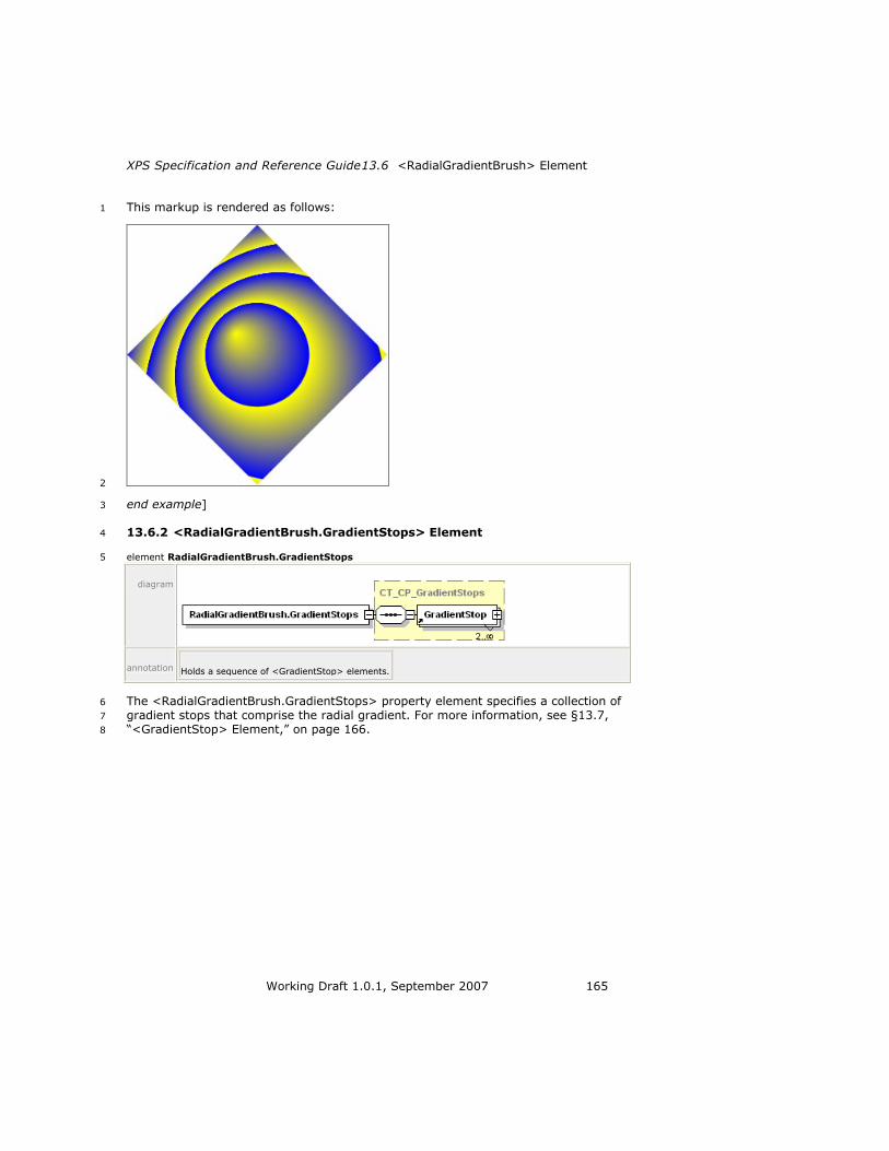
XPS Specification and Reference Guide13.6 <RadialGradientBrush> Element
Working Draft 1.0.1, September 2007 165
This markup is rendered as follows: 1
2
end example] 3
13.6.2 <RadialGradientBrush.GradientStops> Element 4
element RadialGradientBrush.GradientStops 5
diagram
annotation Holds a sequence of <GradientStop> elements.
The <RadialGradientBrush.GradientStops> property element specifies a collection of 6
gradient stops that comprise the radial gradient. For more information, see §13.7, 7
―<GradientStop> Element,‖ on page 166. 8

13.7 <GradientStop> Element Brushes
166 Working Draft 1.0.1, September 2007
13.7 <GradientStop> Element 1
element GradientStop 2
diagram
attributes Name Type Use Default Fixed Annotation
Color ST_Color required Specifies the gradient stop color. An sRGB color
value specified as a 6-digit hexadecimal number
(#RRGGBB) or an extended color.
Offset ST_Double required Specifies the gradient offset. The offset indicates a
point along the progression of the gradient at
which a color is specified. Colors between gradient
offsets in the progression are interpolated.
annotation Indicates a location and range of color progression for rendering a gradient.
The <GradientStop> element is used by both the <LinearGradientBrush> and 3
<RadialGradientBrush> elements to define the location and range of color 4
progression for rendering a gradient. 5
For linear gradient brushes, the offset value of 0.0 is mapped to the start point of the 6
gradient, and the offset value of 1.0 is mapped to the end point. Intermediate offset 7
values are interpolated between these two points to determine their location. 8
For radial gradient brushes, the offset value of 0.0 is mapped to the gradient origin 9
location. The offset value of 1.0 is mapped to the circumference of the ellipse as 10
determined by the center, x radius, and y radius. Offsets between 0.0 and 1.0 are 11
positioned at a location interpolated between these points. 12
For full details of rendering of gradient brushes, including handling of offsets, please 13
see §18.3, ―Gradient Computations‖ on page 272. 14

XPS Specification and Reference Guide13.8 Using a Brush as an Opacity Mask
Working Draft 1.0.1, September 2007 167
13.8 Using a Brush as an Opacity Mask 1
Each pixel carries an alpha value ranging from 0.0 (fully transparent) to 1.0 (fully 2
opaque). The alpha value is used when blending elements to achieve the visual effect 3
of transparency. Each element can have an Opacity attribute by which the alpha 4
value of each pixel is multiplied uniformly. 5
The OpacityMask property also allows the specification of per-pixel opacity, which 6
controls how rendered content is blended with its destination. The opacity specified 7
by the opacity mask is combined multiplicatively with any opacity that may already 8
be present in the alpha channel of the contents. The per-pixel opacity specified by 9
the opacity mask is determined by the alpha channel of each pixel in the mask. The 10
color data is ignored. 11
The alpha value of the area not marked by the brush is 0.0. The required 12
computations for transparently blending two elements when rendering, also known 13
as alpha blending, are described in §18.4, ―Opacity Computations‖ on page 279. 14
An opacity mask always has a brush child element. 15
Example 13–28. Opacity mask with linear gradient 16
The following markup illustrates how an opacity mask is used to create a fade effect 17
on a glyph. The opacity mask is a linear gradient that fades from opaque black to 18
transparent black. 19
<FixedPage Height="1056" Width="816" xml:lang="en-US"> 20
<Glyphs 21
OriginX="25" 22
OriginY="50" 23
UnicodeString="This is a fading text example." 24
FontUri="../Resources/Fonts/Times.TTF" 25
FontRenderingEmSize="32"> 26
<Glyphs.OpacityMask> 27
<LinearGradientBrush 28
StartPoint="25,0" 29
EndPoint="450,0" 30
MappingMode="Absolute"> 31
<LinearGradientBrush.GradientStops> 32
<GradientStop Color="#FF000000" Offset="0" /> 33
<GradientStop Color="#00000000" Offset="1" /> 34
</LinearGradientBrush.GradientStops> 35
</LinearGradientBrush> 36
</Glyphs.OpacityMask> 37
<Glyphs.Fill> 38
<SolidColorBrush Color="#000000" /> 39
</Glyphs.Fill> 40
</Glyphs> 41
</FixedPage> 42
This markup is rendered as follows: 43
44

13.8 Using a Brush as an Opacity Mask Brushes
168 Working Draft 1.0.1, September 2007
end example] 1
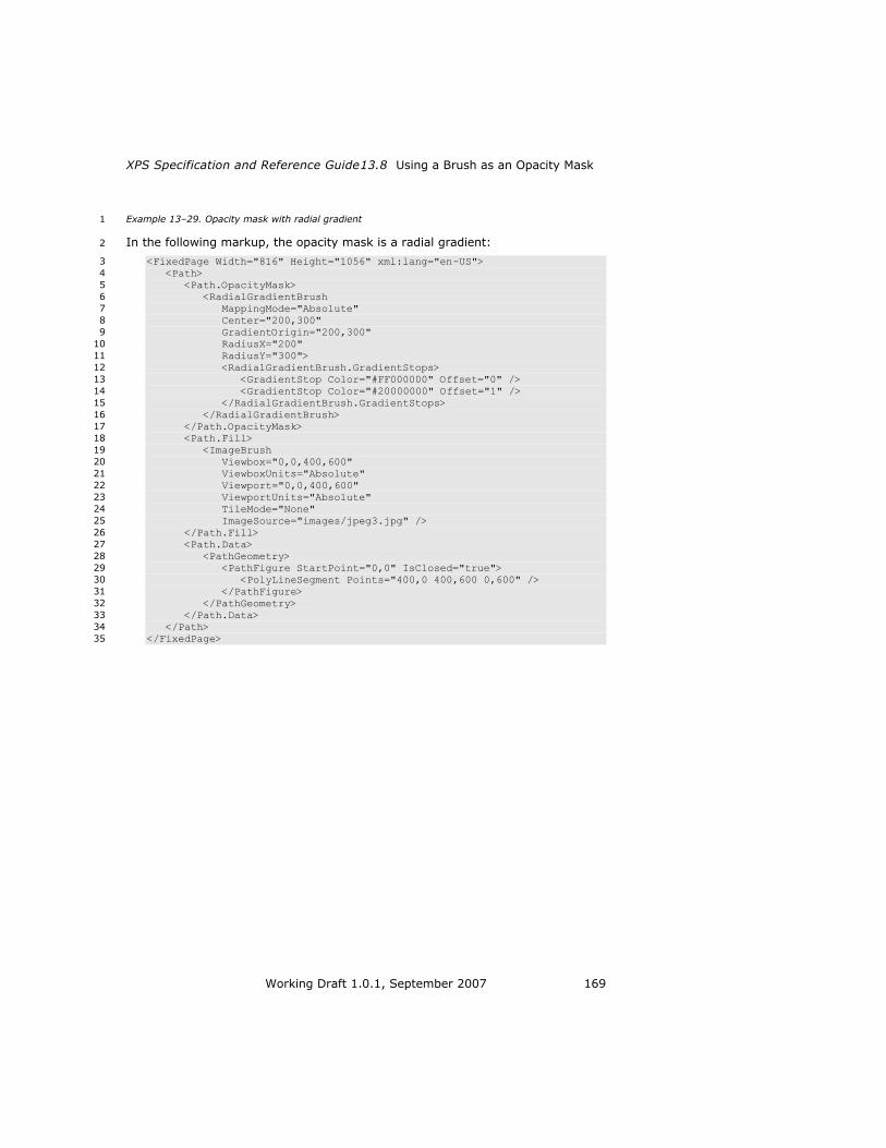
XPS Specification and Reference Guide13.8 Using a Brush as an Opacity Mask
Working Draft 1.0.1, September 2007 169
Example 13–29. Opacity mask with radial gradient 1
In the following markup, the opacity mask is a radial gradient: 2
<FixedPage Width="816" Height="1056" xml:lang="en-US"> 3
<Path> 4
<Path.OpacityMask> 5
<RadialGradientBrush 6
MappingMode="Absolute" 7
Center="200,300" 8
GradientOrigin="200,300" 9
RadiusX="200" 10
RadiusY="300"> 11
<RadialGradientBrush.GradientStops> 12
<GradientStop Color="#FF000000" Offset="0" /> 13
<GradientStop Color="#20000000" Offset="1" /> 14
</RadialGradientBrush.GradientStops> 15
</RadialGradientBrush> 16
</Path.OpacityMask> 17
<Path.Fill> 18
<ImageBrush 19
Viewbox="0,0,400,600" 20
ViewboxUnits="Absolute" 21
Viewport="0,0,400,600" 22
ViewportUnits="Absolute" 23
TileMode="None" 24
ImageSource="images/jpeg3.jpg" /> 25
</Path.Fill> 26
<Path.Data> 27
<PathGeometry> 28
<PathFigure StartPoint="0,0" IsClosed="true"> 29
<PolyLineSegment Points="400,0 400,600 0,600" /> 30
</PathFigure> 31
</PathGeometry> 32
</Path.Data> 33
</Path> 34
</FixedPage> 35
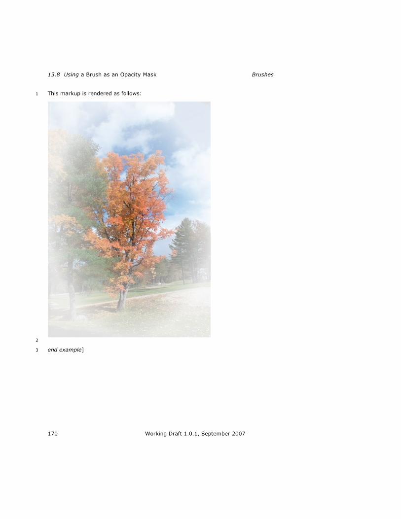
13.8 Using a Brush as an Opacity Mask Brushes
170 Working Draft 1.0.1, September 2007
This markup is rendered as follows: 1
2
end example] 3

XPS Specification and Reference Guide13.8 Using a Brush as an Opacity Mask
Working Draft 1.0.1, September 2007 171
14. Common Properties 1
Several XPS Document elements share property attributes and elements as 2
summarized in Table 14–1 and Table 14–2 and detailed in the following sections. 3
Other than the Name, FixedPage.NavigateUri, and xml:lang attributes, these 4
properties compose their results from parent to child, as described in §18.4.1, ―Pre-5
Multiplied Alpha and Superluminous Colors,‖ on page 281. 6
Table 14–1. Common property attributes 7
Name Applies to Description
Clip <Canvas>
<Glyphs>
<Path>
Restricts the region to which a
brush can be applied.
Opacity <Canvas>
<Glyphs>
<ImageBrush>
<LinearGradientBrush>
<Path>
<RadialGradientBrush>
<SolidColorBrush>
<VisualBrush>
Defines the uniform transparency
of the element.
OpacityMask <Canvas>
<Glyphs>
<Path>
Specifies a mask of alpha values.
RenderTransform <Canvas>
<Glyphs>
<Path>
Establishes a new coordinate space through the use of an affine matrix transformation. For more information, see §14.4,
―Positioning Content,‖ on page 185.
Transform <ImageBrush>
<LinearGradientBrush>
<PathGeometry>
<RadialGradientBrush>
<VisualBrush>
Establishes a new coordinate space
through the use of an affine matrix transformation.
Geometry transformations are applied before brushes. The results are concatenated with any containing effective render transformation specification.
Name <Canvas>
<FixedPage>
<Glyphs>
<Path>
Defines a hyperlink target or identifies an element uniquely for document structure markup to reference. For more information,
see §16.2, ―Hyperlinks,‖ on page 243.

14.1 Opacity Common Properties
172 Working Draft 1.0.1, September 2007
FixedPage.NavigateUri <Canvas>
<Glyphs>
<Path>
Defines a hyperlink source. For more information, see §16.2, ―Hyperlinks,‖ on page 243.
xml:lang <Canvas>
<FixedPage>
<Glyphs>
<Path>
Specifies a language.
Table 14–2. Common property elements 1
Name Description
<Canvas.Resources>
<FixedPage.Resources>
Contains elements that may be reused by
reference throughout the markup of the <FixedPage> or <Canvas> child or descendant elements.
<Canvas.Clip>
<Glyphs.Clip>
<Path.Clip>
Restricts the region to which a brush can be
applied.
<Canvas.RenderTransform>
<Glyphs.RenderTransform>
<Path.RenderTransform>
Establishes a new coordinate space through the
use of an affine matrix transformation. For more information, see §14.4, ―Positioning Content,‖ on
page 185.
<ImageBrush.Transform>
<LinearGradientBrush.Transform>
<PathGeometry.Transform>
<RadialGradientBrush.Transform>
<VisualBrush.Transform>
Establishes a new effective coordinate space
through the use of an affine matrix transformation.
Path geometry transformations (<PathGeometry.Transform>) are applied before brushes. The results are concatenated with any containing effective render transformation.
<Canvas.OpacityMask>
<Glyphs.OpacityMask>
<Path.OpacityMask>
Specifies a mask of alpha values that is applied in the same fashion as the Opacity attribute, but
allows different alpha values on a pixel-by-pixel basis.
14.1 Opacity 2
The Opacity property attribute is used to transparently blend the current element 3
with previously specified elements, also known as alpha blending. The opacity value 4
MUST fall within the 0 (fully transparent) to 1 (fully opaque) range, inclusive 5
[M2.72]. 6
For more information, see §18.4, ―Opacity Computations,‖ on page 279. 7
14.2 Resources and Resource References 8
Fixed page markup supports the concept of resources. A resource is a reusable 9
property value that is expressed in markup, identified by a key, and stored in a 10

XPS Specification and Reference Guide14.2 Resources and Resource References
Working Draft 1.0.1, September 2007 173
resource dictionary. In general, any property value that can be expressed using 1
property element syntax may be held in a resource dictionary. 2
Each resource in a resource dictionary has a key. Any property that specifies its 3
value by referencing a resource key in a resource dictionary is called a resource 4
reference. 5
The <Canvas> and <FixedPage> elements can carry a resource dictionary. A 6
resource dictionary is expressed in markup by the <FixedPage.Resources> or 7
<Canvas.Resources> property element. Individual resource values MUST be 8
specified within a resource dictionary [M7.1]. 9
The <Canvas.Resources> or <FixedPage.Resources> property elements MUST 10
precede any property elements of the <Canvas> or <FixedPage> elements [M2.72]. 11
Likewise, they MUST precede any path, glyphs, or canvas children of the <Canvas> 12
or <FixedPage> elements [M2.72]. 13
Alternatively, resource dictionaries MAY be specified in separate parts and referenced 14
from within the <FixedPage.Resources> or <Canvas.Resources> property element 15
[O7.1]. Such a remote resource dictionary can be shared across multiple pages. 16
[Example: By defining a brush in a remote resource dictionary, graphical elements 17
that are common to multiple pages can be reused. end example] 18
The <Path>, <Glyphs>, and <Canvas> elements can appear as a resource definition 19
solely for the purpose of using these elements in the Visual attribute of a 20
<VisualBrush> element. Brushes and geometries appear in resource dictionaries far 21
more frequently. 22
14.2.1 <FixedPage.Resources> Element 23
element FixedPage.Resources 24
diagram
annotation Contains the resource dictionary for the <FixedPage> element.
Example 14–1. <FixedPage.Resources> usage 25
<FixedPage Width="816" Height="1056" xml:lang="en-US" 26
xmlns="http://schemas.microsoft.com/xps/2005/06" 27
xmlns:x="http://schemas.microsoft.com/xps/2005/06/resourcedictionary- 28
key"> 29
<FixedPage.Resources> 30
<ResourceDictionary> 31
<PathGeometry x:Key="Rectangle"> 32
<PathFigure StartPoint="20,20" IsClosed="true"> 33
<PolyLineSegment Points="120,20 120,70 20,70" /> 34
</PathFigure> 35
</PathGeometry> 36
</ResourceDictionary> 37
</FixedPage.Resources> 38
<Path Stroke="#000000" 39
StrokeThickness="1" 40

14.2 Resources and Resource References Common Properties
174 Working Draft 1.0.1, September 2007
Data="{StaticResource Rectangle}" /> 1
</FixedPage> 2
This markup is rendered as follows: 3
4
end example] 5

XPS Specification and Reference Guide14.2 Resources and Resource References
Working Draft 1.0.1, September 2007 175
14.2.2 <Canvas.Resources> Element 1
element Canvas.Resources 2
diagram
annotation Contains the resource dictionary for the <Canvas> element.
3
Example 14–2. <Canvas.Resources> usage 4
<Canvas 5
xmlns:x="http://schemas.microsoft.com/xps/2005/06/resourcedictionary- 6
key"> 7
<Canvas.Resources> 8
<ResourceDictionary> 9
<PathGeometry x:Key="Circle"> 10
<PathFigure StartPoint="20,70"> 11
<ArcSegment 12
Point="120,70" 13
Size="50,50" 14
RotationAngle="0" 15
IsLargeArc="true" 16
SweepDirection="Clockwise" /> 17
<ArcSegment 18
Point="20,70" 19
Size="50,50" 20
RotationAngle="0" 21
IsLargeArc="true" 22
SweepDirection="Clockwise" /> 23
</PathFigure> 24
</PathGeometry> 25
</ResourceDictionary> 26
</Canvas.Resources> 27
<Path Stroke="#000000" 28
StrokeThickness="1" 29
Data="{StaticResource Circle}" /> 30
</Canvas> 31
This markup is rendered as follows: 32
33
end example] 34

14.2 Resources and Resource References Common Properties
176 Working Draft 1.0.1, September 2007
14.2.3 <ResourceDictionary> Element 1
element ResourceDictionary 2
diagram
attributes Name Type Use Default Fixed Annotation
Source xs:anyURI Specifies the URI of a part containing markup for a
resource dictionary. The URI MUST refer to a part in
the package [M2.1].
annotation Defines a set of reusable resource definitions that can be used as property values in the fixed page
markup.
The <FixedPage.Resources> and <Canvas.Resources> property elements contain 3
exactly one <ResourceDictionary> element. A resource dictionary contains resource 4
definition element entries. Each resource definition has a key specified in the x:Key 5
attribute that is unique within the scope of the resource dictionary. The x:Key 6
attribute is included in the Resource Dictionary namespace specified in H, ―Standard 7
Namespaces and Content Types‖ on page 405. 8
Resource dictionaries can be declared inline inside a <FixedPage.Resources> or 9
<Canvas.Resources> element, or they MAY be defined in a separate part and 10
referenced by a <ResourceDictionary> element inside a <FixedPage.Resources> or 11
<Canvas.Resources> element [O7.1]. This allows resource dictionaries to be shared 12
across parts. [Example: A single resource dictionary can be used by every fixed page 13
in the XPS Document. end example] See §14.2.3.1, ―Remote Resource Dictionaries,‖ 14
on page 177 for more details. 15
A resource definition MAY reference another resource defined previously in the same 16
resource dictionary [O7.2]. If the resource dictionary does not appear in a separate 17

XPS Specification and Reference Guide14.2 Resources and Resource References
Working Draft 1.0.1, September 2007 177
part, a resource definition MAY reference a previously defined resource in a resource 1
dictionary of a parent or ancestor <Canvas> or <FixedPage> element [O7.3]. 2
Namespace prefixes in resource definitions MUST apply in the context of the 3
definition, rather than in the context of the resource reference [M7.2]. An xml:lang 4
attribute within a resource definition MUST be interpreted in the context of the 5
resource reference, not the resource definition [M7.3]. 6
Example 14–3. Resource dictionary markup 7
The following markup defines two geometries, one for a rectangle, and the other for 8
a circle: 9
<Canvas 10
xmlns:x="http://schemas.microsoft.com/xps/2005/06/resourcedictionary- 11
key"> 12
<Canvas.Resources> 13
<ResourceDictionary> 14
<PathGeometry x:Key="Rectangle"> 15
<PathFigure StartPoint="20,20" IsClosed="true"> 16
<PolyLineSegment Points="120,20 120,70 20,70" /> 17
</PathFigure> 18
</PathGeometry> 19
<PathGeometry x:Key="Circle"> 20
<PathFigure StartPoint="20,70"> 21
<ArcSegment 22
Point="120,70" 23
Size="50,50" 24
RotationAngle="0" 25
IsLargeArc="true" 26
SweepDirection="Clockwise" /> 27
<ArcSegment 28
Point="20,70" 29
Size="50,50" 30
RotationAngle="0" 31
IsLargeArc="true" 32
SweepDirection="Clockwise" /> 33
</PathFigure> 34
</PathGeometry> 35
</ResourceDictionary> 36
</Canvas.Resources> 37
<Path Data="{StaticResource Rectangle}"> 38
<Path.Fill> 39
<SolidColorBrush Color="#FF0000" /> 40
</Path.Fill> 41
</Path> 42
</Canvas> 43
end example] 44
14.2.3.1 Remote Resource Dictionaries 45
A resource dictionary MAY be defined in a separate part [O7.1]. This is referred to as 46
a remote resource dictionary. A remote resource dictionary MUST follow the 47
requirements above that apply to all resource dictionaries [M7.4]. A remote resource 48
dictionary MUST NOT contain any resource definition children that reference another 49
remote resource dictionary [M7.5]. 50

14.2 Resources and Resource References Common Properties
178 Working Draft 1.0.1, September 2007
The <FixedPage.Resources> and <Canvas.Resources> property elements include a 1
remote resource dictionary via reference, using the Source attribute of the 2
<ResourceDictionary> element. 3
A <ResourceDictionary> element that specifies a remote resource dictionary in its 4
Source attribute MUST NOT contain any resource definition children [M7.6]. 5
<FixedPage.Resources> and <Canvas.Resources> elements that include a remote 6
resource dictionary MUST include exactly one <ResourceDictionary> element 7
[M2.72]. 8
A remote Resource Dictionary part MUST be added as a Required Resource 9
relationship from the FixedPage part that references it [M2.10]. In addition, 10
producers MUST add each resource such as fonts or images referenced in the 11
Resource Dictionary part as a Required Resource relationship from the FixedPage 12
part (not the Resource Dictionary part) to the indirectly required resource, even if 13
the particular fixed page does not reference the resource [M2.10]. For more 14
information, see §H.3, ―Relationship Types,‖ on page 407. 15
Inline references to fonts or images in remote resource dictionary entries MUST be 16
interpreted with the same base URI as the Remote Resource Dictionary part, not 17
from the base URI of the part referring to the particular remote resource dictionary 18
entry [M7.7]. 19
Example 14–4. A remote resource dictionary and reference 20
The following markup defines a resource dictionary that contains two geometries, 21
one for a rectangle and the other for a circle: 22
<!-- Contents of /resource.xaml --> 23
<ResourceDictionary xmlns="http://schemas.microsoft.com/xps/2005/06" 24
xmlns:x="http://schemas.microsoft.com/xps/2005/06/resourcedictionary- 25
key"> 26
<PathGeometry x:Key="Rectangle"> 27
<PathFigure StartPoint="20,20" IsClosed="true"> 28
<PolyLineSegment Points="120,20 120,70 20,70" /> 29
</PathFigure> 30
</PathGeometry> 31
<PathGeometry x:Key="Circle"> 32
<PathFigure StartPoint="20,70"> 33
<ArcSegment 34
Point="120,70" 35
Size="50,50" 36
RotationAngle="0" 37
IsLargeArc="true" 38
SweepDirection="Clockwise" /> 39
<ArcSegment 40
Point="20,70" 41
Size="50,50" 42
RotationAngle="0" 43
IsLargeArc="true" 44
SweepDirection="Clockwise" /> 45
</PathFigure> 46
</PathGeometry> 47
</ResourceDictionary> 48
The following markup references the previously defined resource dictionary: 49
<Canvas 50
xmlns:x="http://schemas.microsoft.com/xps/2005/06/resourcedictionary- 51
key"> 52

XPS Specification and Reference Guide14.2 Resources and Resource References
Working Draft 1.0.1, September 2007 179
<Canvas.Resources> 1
<ResourceDictionary Source="/resource.xaml"/> 2
</Canvas.Resources> 3
<Path Data="{StaticResource Rectangle}"> 4
<Path.Fill> 5
<SolidColorBrush Color="#FF0000" /> 6
</Path.Fill> 7
</Path> 8
</Canvas> 9
end example] 10

14.2 Resources and Resource References Common Properties
180 Working Draft 1.0.1, September 2007
14.2.4 Resource References 1
To set a property value to a defined resource, use the form: 2
{StaticResource key} 3
Where key is the same string specified with x:Key in the resource definition. 4
The context of the resource reference determines how defined resources are 5
rendered (such as the transformation matrix to be applied). Specifically, the effective 6
coordinate space for rendering the referenced resource is a composition of the 7
effective coordinate space of the referring element plus any Transform or 8
RenderTransform properties included in the resource definition itself. 9
It is considered an error if a static resource reference cannot be resolved, or if it can 10
be resolved but the resource type does not match the usage at the location of 11
reference. 12
Example 14–5. Using a resource reference to fill a brush 13
In the following markup, the rectangular region defined by the geometry specified in 14
the dictionary is filled by a solid color brush: 15
<Canvas 16
xmlns:x="http://schemas.microsoft.com/xps/2005/06/resourcedictionary- 17
key"> 18
<Canvas.Resources> 19
<ResourceDictionary> 20
<PathGeometry x:Key="Rectangle"> 21
<PathFigure StartPoint="20,20" IsClosed="true"> 22
<PolyLineSegment Points="120,20 120,70 20,70" /> 23
</PathFigure> 24
</PathGeometry> 25
</ResourceDictionary> 26
</Canvas.Resources> 27
<Path Data="{StaticResource Rectangle}"> 28
<Path.Fill> 29
<SolidColorBrush Color="#FF0000" /> 30
</Path.Fill> 31
</Path> 32
</Canvas> 33
end example] 34
14.2.5 Scoping Rules for Resolving Resource References 35
The value of the x:Key attribute MUST be unique within the resource dictionary 36
[M2.72]. However, the resource dictionary of a <Canvas> element MAY re-use an 37
x:Key value defined in the resource dictionary of a parent or ancestor <Canvas> or 38
<FixedPage> element [O7.5]. Resource references are resolved from the innermost 39
to the outermost resource dictionary. 40
A resource definition MAY reference a previously defined resource with the same 41
name that is defined in an ancestor resource dictionary [O7.6]; the reference MUST 42
be resolved before the redefined resource is added to the dictionary [M7.8]. 43
A resource definition MAY reference another resource defined prior to the point of 44
reference, including a resource previously defined within the same resource 45

XPS Specification and Reference Guide14.2 Resources and Resource References
Working Draft 1.0.1, September 2007 181
dictionary [O7.2]. If a resource definition references another resource, the reference 1
MUST be resolved in the context of the resource definition, not in the context of the 2
resource use [M7.9]. 3
To find a resource, the nearest parent or ancestor canvas or fixed page is searched. 4
If the desired name is not defined in the initially searched resource dictionary, then 5
the next-nearest parent or ancestor canvas or fixed page is searched. An error 6
occurs if the search has continued to the root <FixedPage> element and a specified 7
resource has not been found. This search occurs only within the containing FixedPage 8
part. 9
Example 14–6. Using scoping rules 10
<FixedPage 11
xmlns="http://schemas.microsoft.com/xps/2005/06" 12
xmlns:x="http://schemas.microsoft.com/xps/2005/06/resourcedictionary- 13
key" 14
Height="1056" Width="816" xml:lang="en-US"> 15
<FixedPage.Resources> 16
<ResourceDictionary> 17
<SolidColorBrush x:Key="FavoriteColorFill" Color="#808080" /> 18
</ResourceDictionary> 19
</FixedPage.Resources> 20
<Canvas> 21
<Canvas.Resources> 22
<ResourceDictionary> 23
<SolidColorBrush x:Key="FavoriteColorFill" 24
Color="#000000" /> 25
</ResourceDictionary> 26
</Canvas.Resources> 27
<!-- The following path is filed with color #000000 --> 28
<Path Fill="{StaticResource FavoriteColorFill}"> 29
<Path.Data> 30
... 31
</Path.Data> 32
</Path> 33
<Canvas> 34
<!-- The following path is filed with color #000000 --> 35
<Path Fill="{StaticResource FavoriteColorFill}"> 36
<Path.Data> 37
... 38
</Path.Data> 39
</Path> 40
</Canvas> 41
</Canvas> 42
<!-- The following path is filled with color #808080 --> 43
<Path Fill="{StaticResource FavoriteColorFill}"> 44
<Path.Data> 45
... 46
</Path.Data> 47
</Path> 48
</FixedPage> 49
end example] 50
14.2.6 Support for Markup Compatibility 51
If a resource dictionary contains Markup Compatibility elements and attributes, the 52
processing of the Markup Compatibility markup MUST occur in the context of the 53
definition of the resource dictionary, not in the context of resource references 54
[M2.10]. 55
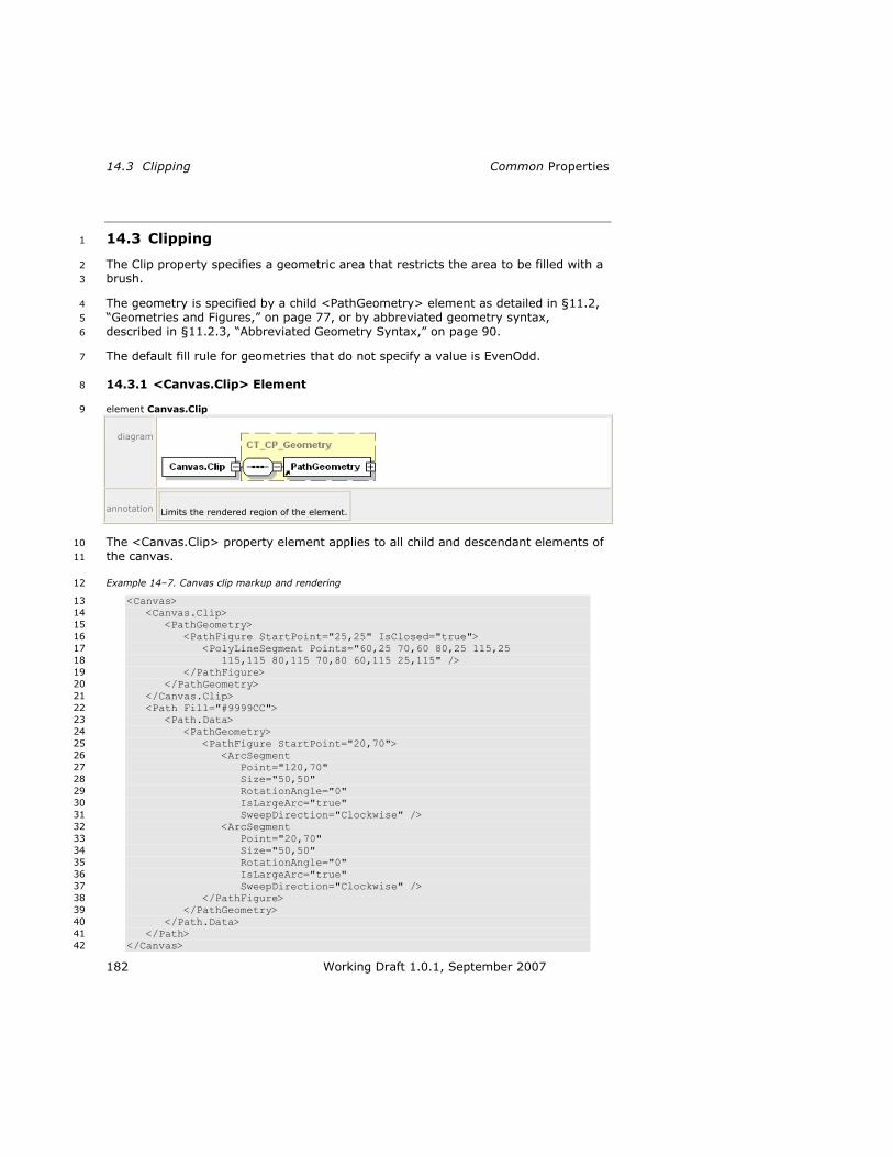
14.3 Clipping Common Properties
182 Working Draft 1.0.1, September 2007
14.3 Clipping 1
The Clip property specifies a geometric area that restricts the area to be filled with a 2
brush. 3
The geometry is specified by a child <PathGeometry> element as detailed in §11.2, 4
―Geometries and Figures,‖ on page 77, or by abbreviated geometry syntax, 5
described in §11.2.3, ―Abbreviated Geometry Syntax,‖ on page 90. 6
The default fill rule for geometries that do not specify a value is EvenOdd. 7
14.3.1 <Canvas.Clip> Element 8
element Canvas.Clip 9
diagram
annotation Limits the rendered region of the element.
The <Canvas.Clip> property element applies to all child and descendant elements of 10
the canvas. 11
Example 14–7. Canvas clip markup and rendering 12
<Canvas> 13
<Canvas.Clip> 14
<PathGeometry> 15
<PathFigure StartPoint="25,25" IsClosed="true"> 16
<PolyLineSegment Points="60,25 70,60 80,25 115,25 17
115,115 80,115 70,80 60,115 25,115" /> 18
</PathFigure> 19
</PathGeometry> 20
</Canvas.Clip> 21
<Path Fill="#9999CC"> 22
<Path.Data> 23
<PathGeometry> 24
<PathFigure StartPoint="20,70"> 25
<ArcSegment 26
Point="120,70" 27
Size="50,50" 28
RotationAngle="0" 29
IsLargeArc="true" 30
SweepDirection="Clockwise" /> 31
<ArcSegment 32
Point="20,70" 33
Size="50,50" 34
RotationAngle="0" 35
IsLargeArc="true" 36
SweepDirection="Clockwise" /> 37
</PathFigure> 38
</PathGeometry> 39
</Path.Data> 40
</Path> 41
</Canvas> 42

XPS Specification and Reference Guide 14.3 Clipping
Working Draft 1.0.1, September 2007 183
This markup is rendered as follows: 1
2
end example] 3
14.3.2 <Path.Clip> Element 4
element Path.Clip 5
diagram
annotation Limits the rendered region of the element.
A clipping region may also be applied to a specific path. 6
Example 14–8. <Path.Clip> usage 7
The following markup describes a complex clipping behavior: 8
<Path Fill="#9999CC"> 9
<Path.Clip> 10
<PathGeometry> 11
<PathFigure StartPoint="25,25" IsClosed="true"> 12
<PolyLineSegment Points="115,25 115,115 25,115" /> 13
</PathFigure> 14
<PathFigure StartPoint="55,55" IsClosed="true"> 15
<PolyLineSegment Points="85,55 85,85 55,85" /> 16
</PathFigure> 17
</PathGeometry> 18
</Path.Clip> 19
<Path.Data> 20
<PathGeometry> 21
<PathFigure StartPoint="20,70"> 22
<ArcSegment 23
Point="120,70" 24
Size="50,50" 25
RotationAngle="0" 26
IsLargeArc="true" 27
SweepDirection="Clockwise" /> 28
<ArcSegment 29
Point="20,70" 30
Size="50,50" 31
RotationAngle="0" 32
IsLargeArc="true" 33
SweepDirection="Clockwise" /> 34
</PathFigure> 35
</PathGeometry> 36
</Path.Data> 37

14.3 Clipping Common Properties
184 Working Draft 1.0.1, September 2007
</Path> 1
This markup is rendered as follows: 2
3
end example] 4
14.3.3 <Glyphs.Clip> Element 5
element Glyphs.Clip 6
diagram
annotation Limits the rendered region of the element. Only portions of the <Glyphs> element that fall within
the clip region (even partially clipped characters) produce marks on the page.
Example 14–9. <Glyphs.Clip> usage 7
The following markup uses abbreviated geometry syntax to define the clipping 8
region: 9
<Glyphs 10
Fill="#000000" 11
Clip="M 0,0 L 180,0 L 180,140 L 0,140 Z M 20,60 L 140,60 L 140,80 12
L 20,80 Z" 13
OriginX="20" 14
OriginY="130" 15
UnicodeString="N" 16
FontRenderingEmSize="170" 17
FontUri="../Resources/Fonts/Timesbd.ttf" /> 18
This markup is rendered as follows: 19
20
end example] 21

XPS Specification and Reference Guide 14.4 Positioning Content
Working Draft 1.0.1, September 2007 185
14.4 Positioning Content 1
Content is positioned according to the properties specified for the fixed page or 2
canvas, the properties specified for elements within the fixed page or canvas, and 3
the compositional rules defined for the fixed payload namespace. 4
Elements are positioned relative to the current origin (0,0) of the coordinate space. 5
The current origin can be moved by setting the RenderTransform property of a 6
canvas, path, or glyph. The render transformation establishes a new coordinate 7
frame for all children of the parent element. 8
Geometries and brushes may be manipulated in a similar way by setting the 9
Transform property. The transform results are concatenated with the current render 10
transformation to create an effective render transformation for the local element. 11
The RenderTransform and Transform properties both specify an affine matrix 12
transformation to the local coordinate space, using the <MatrixTransform> element 13
as their value. An abbreviated matrix transformation syntax MAY be used to specify a 14
RenderTransform or Transform attribute value [M2.72]. 15
14.4.1 <MatrixTransform> Element 16
element MatrixTransform 17
diagram
attributes Name Type Use Default Fixed Annotation
Matrix ST_Matrix required Specifies the matrix structure that defines the
transformation.
x:Key Specifies a name for a resource in a resource
dictionary. x:Key MUST be present when the
current element is defined in a resource dictionary.
x:Key MUST NOT be specified outside of a
resource dictionary [M7.11].
annotation Creates an arbitrary affine matrix transformation that manipulates objects or coordinate systems in
a two-dimensional plane.
The <MatrixTransform> element defines an arbitrary affine matrix transformation 18
used to manipulate the coordinate systems of elements. A 3x3 matrix is used for 19
transformations in an x,y plane. Affine transformation matrices can be multiplied to 20
form any number of linear transformations, such as rotation and skew (shear), 21
followed by translation. An affine transformation matrix has its final column equal to 22
0,0,1, so only the members in the first two columns are specified. 23

14.4 Positioning Content Common Properties
186 Working Draft 1.0.1, September 2007
1
[
] M11 M12 0
M21 M22 0
OffsetX OffsetY 1
This structure is specified by the Matrix attribute of the <MatrixTransform> element 2
as the six numbers in the first two columns. [Example: 3
―M11,M12,M21,M22,OffsetX,OffsetY‖. end example] 4
A matrix transform may also be specified as a RenderTransform or Transform 5
property attribute using the following abbreviated matrix transformation syntax: 6
M11,M12,M21,M22,OffsetX,OffsetY 7
The values M11, M12, M21, and M22 control linear transformations such as rotation 8
and skew, while OffsetX and OffsetY provide positional translation. Some typical 9
affine matrix transformation examples follow. 10
Example 14–10. Matrix scaling 11
[
] X scale-factor
0 0
0 Y scale-factor
0
0 0 1
end example] 12
Example 14–11. Matrix reversing the x axis 13
[
] -1 0 0
0 1 0
0 0 1
end example] 14
Example 14–12. Matrix reversing the y axis 15
[
] 1 0 0
0 -1 0
0 0 1
end example] 16
Example 14–13. Matrix skewing 17
[
] 1 Y skew-factor
0
X skew- 1 0

XPS Specification and Reference Guide 14.4 Positioning Content
Working Draft 1.0.1, September 2007 187
factor
0 0 1
end example] 1
Example 14–14. Matrix Rotating 2
[
] cos Θ sin Θ 0
-sin Θ cos Θ 0
0 0 1
end example] 3
Example 14–15. Matrix positioning 4
[
] 1 0 0
0 1 0
OffsetX OffsetY 1
end example] 5
Example 14–16. <MatrixTransform> usage 6
The following markup describes a box (with the top edge marked) that is rotated 90° 7
and shifted 50 units down and to the right: 8
<Path 9
Stroke="#000000" 10
Fill="#9999BB" 11
Data="M 0,0 L 60,0 L 60,25 L 60,0 L 120,0 L 120,120 L 0,120 Z"> 12
<Path.RenderTransform> 13
<MatrixTransform Matrix="0,1,-1,0,170,50" /> 14
</Path.RenderTransform> 15
</Path> 16
Since the x origin has been shifted, the overall box must be additionally shifted the 17
width of the box to achieve the desired visual effect. 18
Before the render transformation, the box appears like this: 19
20

14.4 Positioning Content Common Properties
188 Working Draft 1.0.1, September 2007
After the render transformation, the box appears like this: 1
2
end example] 3
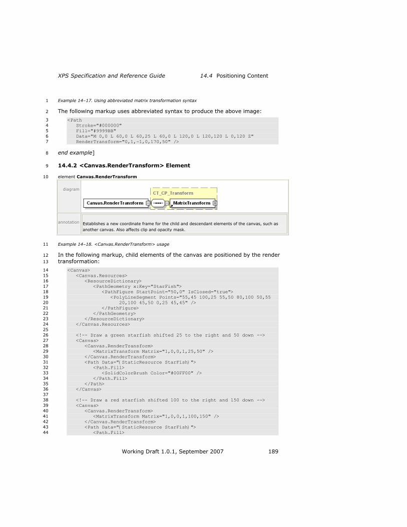
XPS Specification and Reference Guide 14.4 Positioning Content
Working Draft 1.0.1, September 2007 189
Example 14–17. Using abbreviated matrix transformation syntax 1
The following markup uses abbreviated syntax to produce the above image: 2
<Path 3
Stroke="#000000" 4
Fill="#9999BB" 5
Data="M 0,0 L 60,0 L 60,25 L 60,0 L 120,0 L 120,120 L 0,120 Z" 6
RenderTransform="0,1,-1,0,170,50" /> 7
end example] 8
14.4.2 <Canvas.RenderTransform> Element 9
element Canvas.RenderTransform 10
diagram
annotation Establishes a new coordinate frame for the child and descendant elements of the canvas, such as
another canvas. Also affects clip and opacity mask.
Example 14–18. <Canvas.RenderTransform> usage 11
In the following markup, child elements of the canvas are positioned by the render 12
transformation: 13
<Canvas> 14
<Canvas.Resources> 15
<ResourceDictionary> 16
<PathGeometry x:Key="StarFish"> 17
<PathFigure StartPoint="50,0" IsClosed="true"> 18
<PolyLineSegment Points="55,45 100,25 55,50 80,100 50,55 19
20,100 45,50 0,25 45,45" /> 20
</PathFigure> 21
</PathGeometry> 22
</ResourceDictionary> 23
</Canvas.Resources> 24
25
<!-- Draw a green starfish shifted 25 to the right and 50 down --> 26
<Canvas> 27
<Canvas.RenderTransform> 28
<MatrixTransform Matrix="1,0,0,1,25,50" /> 29
</Canvas.RenderTransform> 30
<Path Data="{StaticResource StarFish}"> 31
<Path.Fill> 32
<SolidColorBrush Color="#00FF00" /> 33
</Path.Fill> 34
</Path> 35
</Canvas> 36
37
<!-- Draw a red starfish shifted 100 to the right and 150 down --> 38
<Canvas> 39
<Canvas.RenderTransform> 40
<MatrixTransform Matrix="1,0,0,1,100,150" /> 41
</Canvas.RenderTransform> 42
<Path Data="{StaticResource StarFish}"> 43
<Path.Fill> 44

14.4 Positioning Content Common Properties
190 Working Draft 1.0.1, September 2007
<SolidColorBrush Color="#FF0000" /> 1
</Path.Fill> 2
</Path> 3
</Canvas> 4
</Canvas> 5
This markup is rendered as follows: 6
7
end example] 8
14.4.3 <Path.RenderTransform> Element 9
element Path.RenderTransform 10
diagram
annotation Establishes a new coordinate frame for all attributes of the path and for all child elements of the
path, such as the geometry defined by the <Path.Data> property element.
Example 14–19. <Path.RenderTransform> usage 11
The following markup describes a y-skew transformation applied to a circular path. 12
(Before the render transformation, the middle of the right edge of the circle was 13
marked with a horizontal line.) 14
<Path 15
Fill="#999999" 16
Stroke="#000000" 17
Data="M 20,70 A 50,50 0 1 1 120,70 L 100,70 L 120,70 A 50,50 0 1 1 18
20,70 Z" 19
RenderTransform="1,0.5,0,1,0,0" /> 20

XPS Specification and Reference Guide 14.4 Positioning Content
Working Draft 1.0.1, September 2007 191
This markup is rendered as follows: 1
2
end example] 3
14.4.4 <Glyphs.RenderTransform> Element 4
element Glyphs.RenderTransform 5
diagram
annotation Establishes a new coordinate frame for the glyph run specified by the <Glyphs> element. The
render transform affects clip, opacity mask, fill, x origin, y origin, the actual shape of individual
glyphs, and the advance widths. The render transform also affects the font size and values specified
in the Indices attribute.
Example 14–20. <Glyphs.RenderTransform> usage 6
The following markup describes the letter J, flipped vertically and repositioned. 7
<Glyphs 8
Fill="#000000" 9
OriginX="20" 10
OriginY="130" 11
UnicodeString="J" 12
FontRenderingEmSize="170" 13
FontUri="../Resources/Fonts/Timesbd.ttf" 14
RenderTransform="1,0,0,-1,0,150" /> 15
This markup is rendered as follows: 16
17
end example] 18

14.4 Positioning Content Common Properties
192 Working Draft 1.0.1, September 2007
14.4.5 <PathGeometry.Transform> Element 1
element PathGeometry.Transform 2
diagram
annotation Specifies the local matrix transformation that is applied to all child and descendant elements of the
path geometry before it is used for filling, clipping, or stroking.
Example 14–21. <PathGeometry.Transform> usage 3
The following markup demonstrates a simple 150% zoom and positional 4
transformation: 5
<Path StrokeThickness="2" Stroke="#000000"> 6
<Path.Data> 7
<PathGeometry Transform="1.5,0,0,1.5,20,20"> 8
<PathFigure StartPoint="50,0" IsClosed="true"> 9
<PolyLineSegment Points="150,0 200,100 0,100" /> 10
</PathFigure> 11
</PathGeometry> 12
</Path.Data> 13
</Path> 14
This markup is rendered as follows. The pre-transform path is indicated in light gray. 15
Note that the stroke thickness did not change. If this transformation had been 16
applied to the entire Path, the stroke thickness would also have increased by 150%. 17
18
end example] 19

XPS Specification and Reference Guide 14.4 Positioning Content
Working Draft 1.0.1, September 2007 193
14.4.6 <ImageBrush.Transform> Element 1
element ImageBrush.Transform 2
diagram
annotation Describes the matrix transformation applied to the coordinate space of the brush. The Transform
property is concatenated with the current effective render transform to yield an effective render
transform local to the brush. The viewport for the brush is transformed using the local effective
render transform.
The Transform property can result in a non-rectangular (that is, skewed) viewport 3
that defines the tile shape. In this circumstance, tile mode operations (FlipX, FlipY, 4
and FlipXY) are treated as if the tile was rectangular, a larger tile was constructed 5
from a 2-by-2 arrangement of regular tiles, the skew transform was applied 6
afterward, and the new non-rectangular tile was tiled with adjacent edges and 7
without flipping. 8
Example 14–22. <ImageBrush.Transform> usage 9
The following markup describes an image rotated 20° and repositioned within a path. 10
The path itself remains untransformed; the viewport of the image brush is 11
transformed instead. 12
<Path 13
StrokeThickness="5" 14
Stroke="#996666" 15
StrokeLineJoin="Round" 16
Data="M 25,25 L 350,25 L 355,250 L 25,250 Z"> 17
<Path.Fill> 18
<ImageBrush 19
ImageSource="dog.jpg" 20
Transform=".939,.342,-.342,.939,0,-80" 21
TileMode="Tile" 22
Viewbox="0,0,270,423" 23
ViewboxUnits="Absolute" 24
Viewport="75,75,90,125" 25
ViewportUnits="Absolute" /> 26
</Path.Fill> 27
</Path> 28
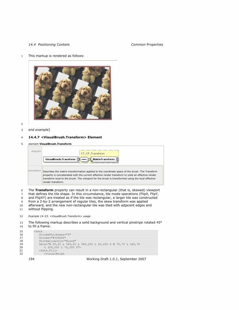
14.4 Positioning Content Common Properties
194 Working Draft 1.0.1, September 2007
This markup is rendered as follows: 1
2
end example] 3
14.4.7 <VisualBrush.Transform> Element 4
element VisualBrush.Transform 5
diagram
annotation Describes the matrix transformation applied to the coordinate space of the brush. The Transform
property is concatenated with the current effective render transform to yield an effective render
transform local to the brush. The viewport for the brush is transformed using the local effective
render transform.
The Transform property can result in a non-rectangular (that is, skewed) viewport 6
that defines the tile shape. In this circumstance, tile mode operations (FlipX, FlipY, 7
and FlipXY) are treated as if the tile was rectangular, a larger tile was constructed 8
from a 2-by-2 arrangement of regular tiles, the skew transform was applied 9
afterward, and the new non-rectangular tile was tiled with adjacent edges and 10
without flipping. 11
Example 14–23. <VisualBrush.Transform> usage 12
The following markup describes a solid background and vertical pinstripe rotated 45° 13
to fill a frame: 14
<Path 15
StrokeThickness="5" 16
Stroke="#336666" 17
StrokeLineJoin="Round" 18
Data="M 25,25 L 365,25 L 365,250 L 25,250 Z M 70,70 L 320,70 19
L 320,205 L 70,205 Z"> 20
<Path.Fill> 21
<VisualBrush 22

XPS Specification and Reference Guide 14.4 Positioning Content
Working Draft 1.0.1, September 2007 195
Transform=".707,.707,-.707,.707,0,0" 1
TileMode="Tile" 2
Viewbox="0,0,60,100" 3
ViewboxUnits="Absolute" 4
Viewport="25,25,50,50" 5
ViewportUnits="Absolute"> 6
<VisualBrush.Visual> 7
<Canvas> 8
<Path 9
Fill="#99CCCC" 10
Data="M 0,0 L 60,0 L 60,100 L 0,100 Z" /> 11
<Path 12
Stroke="#336666" 13
Data="M 0,0 L 0,100 M 20,0 L 20,100 M 40,0 L 40,100 14
M 60,0 L 60,100 M 80,0 L 80,100" /> 15
</Canvas> 16
</VisualBrush.Visual> 17
</VisualBrush> 18
</Path.Fill> 19
</Path> 20
This markup is rendered as follows: 21
22
end example] 23

14.4 Positioning Content Common Properties
196 Working Draft 1.0.1, September 2007
Example 14–24. <VisualBrush.Transform> usage with tiling behavior 1
This example demonstrates tile rendering behavior when applying a transform. 2
<!-- Draw background diamond to show where fill affects background --> 3
<Path Fill="#CCCC66" Data="M 200,0 L 400,200 L 200,400 L 0,200 Z" /> 4
<Path Data="M 200,0 L 400,200 L 200,400 L 0,200 Z"> 5
<Path.Fill> 6
<VisualBrush 7
Viewbox="0,0,1,1" 8
Viewport="200,133,67,67" 9
ViewboxUnits="Absolute" 10
ViewportUnits="Absolute" 11
Transform="1,0,1,1,0,0" 12
TileMode="FlipY"> 13
<VisualBrush.Visual> 14
<Canvas> 15
<Path Fill="#333399" Data="M 0.1,0.1 L 0.9,0.1 L 0.9,0.9 16
L 0.1,0.9 Z" /> 17
<Path Fill="#FFFF00" Data="M 0.1,0.35 L 0.35,0.1 18
L 0.6,0.35 L 0.35,0.6 Z" /> 19
</Canvas> 20
</VisualBrush.Visual> 21
</VisualBrush> 22
</Path.Fill> 23
</Path> 24
This markup is rendered as follows: 25
26
end example] 27
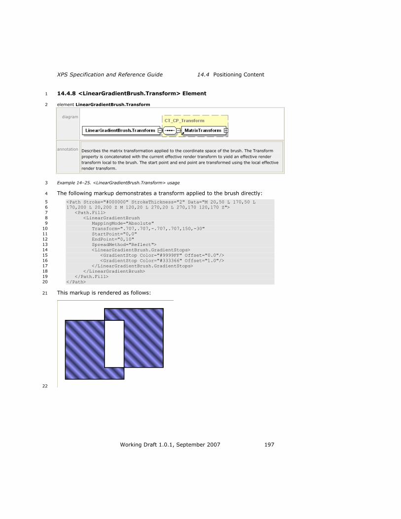
XPS Specification and Reference Guide 14.4 Positioning Content
Working Draft 1.0.1, September 2007 197
14.4.8 <LinearGradientBrush.Transform> Element 1
element LinearGradientBrush.Transform 2
diagram
annotation Describes the matrix transformation applied to the coordinate space of the brush. The Transform
property is concatenated with the current effective render transform to yield an effective render
transform local to the brush. The start point and end point are transformed using the local effective
render transform.
Example 14–25. <LinearGradientBrush.Transform> usage 3
The following markup demonstrates a transform applied to the brush directly: 4
<Path Stroke="#000000" StrokeThickness="2" Data="M 20,50 L 170,50 L 5
170,200 L 20,200 Z M 120,20 L 270,20 L 270,170 120,170 Z"> 6
<Path.Fill> 7
<LinearGradientBrush 8
MappingMode="Absolute" 9
Transform=".707,.707,-.707,.707,150,-30" 10
StartPoint="0,0" 11
EndPoint="0,10" 12
SpreadMethod="Reflect"> 13
<LinearGradientBrush.GradientStops> 14
<GradientStop Color="#9999FF" Offset="0.0"/> 15
<GradientStop Color="#333366" Offset="1.0"/> 16
</LinearGradientBrush.GradientStops> 17
</LinearGradientBrush> 18
</Path.Fill> 19
</Path> 20
This markup is rendered as follows: 21
22

14.4 Positioning Content Common Properties
198 Working Draft 1.0.1, September 2007
Without the Transform property, this markup would be rendered as follows: 1
2
end example] 3
14.4.9 <RadialGradientBrush.Transform> Element 4
element RadialGradientBrush.Transform 5
diagram
annotation Describes the matrix transformation applied to the coordinate space of the brush. The Transform
property is concatenated with the current effective render transform to yield an effective render
transform local to the brush. The ellipse defined by the center, gradient origin, x radius, and y radius
vaules is transformed using the local effective render transform.
Example 14–26. <RadialGradientBrush.Transform> usage 6
The following markup describes a rotation and reposition transform on a radial 7
gradient: 8
<Path 9
Stroke="#000000" 10
StrokeThickness="2" 11
Data="M 20,20 L 270,20 L 270,200 L 20,200 Z"> 12
<Path.Fill> 13
<RadialGradientBrush 14
MappingMode="Absolute" 15
Transform=".707,.707,-.707,.707,150,-10" 16
Center="80,90" 17
RadiusX="50" 18
RadiusY="80" 19
GradientOrigin="70,15" 20
SpreadMethod="Reflect"> 21
<RadialGradientBrush.GradientStops> 22
<GradientStop Color="#9999FF" Offset="0.0" /> 23
<GradientStop Color="#333366" Offset="1.0" /> 24
</RadialGradientBrush.GradientStops> 25
</RadialGradientBrush> 26
</Path.Fill> 27
</Path> 28

XPS Specification and Reference Guide 14.4 Positioning Content
Working Draft 1.0.1, September 2007 199
This markup is rendered as follows: 1
2
Without the Transform property, this markup is rendered as follows: 3
4
end example] 5

14.5 OpacityMask Common Properties
200 Working Draft 1.0.1, September 2007
14.5 OpacityMask 1
The OpacityMask property defines a variable alpha mask for the parent element. The 2
alpha for areas not marked by the brush is 0.0. 3
14.5.1 <Canvas.OpacityMask> Element 4
element Canvas.OpacityMask 5
diagram
annotation Specifies a mask of alpha values that is applied to the canvas in the same fashion as the Opacity
attribute, but allowing different alpha values for different areas of the element.
Example 14–27. <Canvas.OpacityMask> usage 6
In the following markup, the contents of the canvas are opaque with respect to each 7
other, but both elements are blended with the background triangle: 8
<Path Fill="#CCCC66" Data="M 10,10 L 300,80 L 180,240 Z" /> 9
<Canvas> 10
<Canvas.OpacityMask> 11
<LinearGradientBrush 12
MappingMode="Absolute" 13
StartPoint="0,150" 14
EndPoint="0,175" 15
SpreadMethod="Pad"> 16
<LinearGradientBrush.GradientStops> 17
<GradientStop Color="#40000000" Offset="0.0" /> 18
<GradientStop Color="#FF000000" Offset="1.0" /> 19
</LinearGradientBrush.GradientStops> 20
</LinearGradientBrush> 21
</Canvas.OpacityMask> 22
<Path 23
Stroke="#000000" 24
StrokeThickness="2" 25
Fill="#333399" 26
Data="M 20,40 L 270,40 L 270,200 L 20,200 Z" /> 27
<Glyphs 28
OriginX="30" 29
OriginY="180" 30
UnicodeString="EXAMPLE" 31
FontUri="../Resources/Fonts/Timesbd.ttf" 32
FontRenderingEmSize="48" 33
Fill="#FFFFFF" /> 34
</Canvas> 35
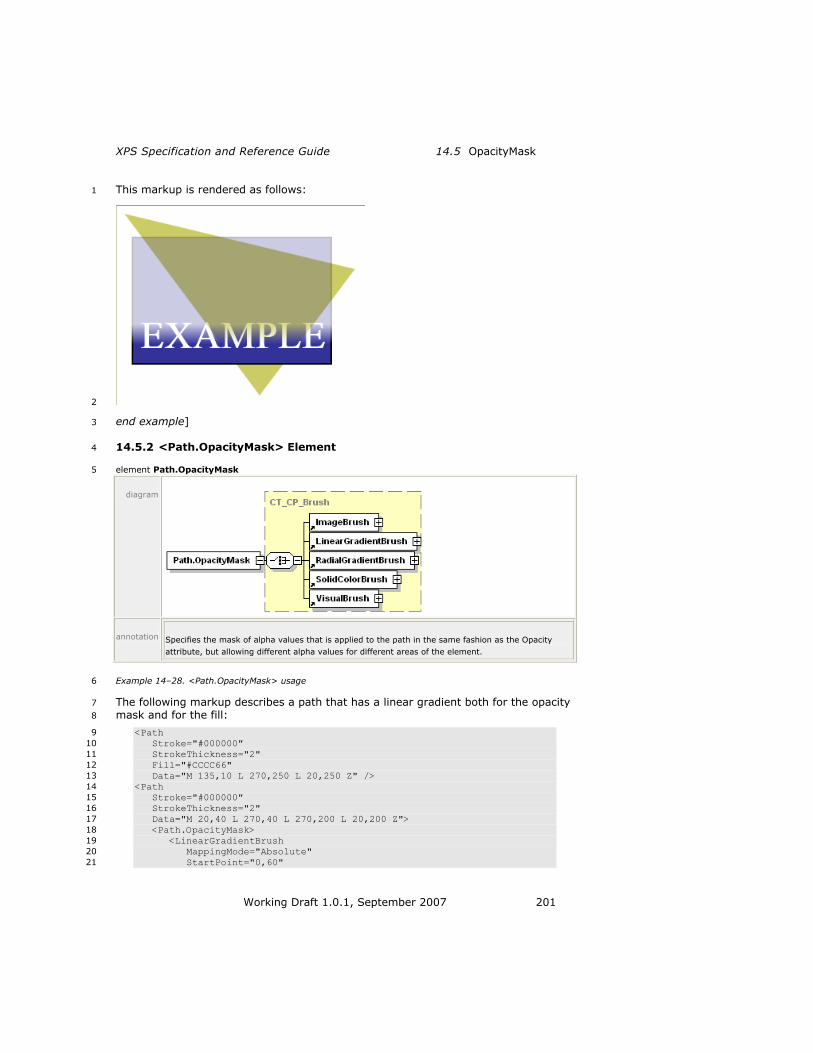
XPS Specification and Reference Guide 14.5 OpacityMask
Working Draft 1.0.1, September 2007 201
This markup is rendered as follows: 1
2
end example] 3
14.5.2 <Path.OpacityMask> Element 4
element Path.OpacityMask 5
diagram
annotation Specifies the mask of alpha values that is applied to the path in the same fashion as the Opacity
attribute, but allowing different alpha values for different areas of the element.
Example 14–28. <Path.OpacityMask> usage 6
The following markup describes a path that has a linear gradient both for the opacity 7
mask and for the fill: 8
<Path 9
Stroke="#000000" 10
StrokeThickness="2" 11
Fill="#CCCC66" 12
Data="M 135,10 L 270,250 L 20,250 Z" /> 13
<Path 14
Stroke="#000000" 15
StrokeThickness="2" 16
Data="M 20,40 L 270,40 L 270,200 L 20,200 Z"> 17
<Path.OpacityMask> 18
<LinearGradientBrush 19
MappingMode="Absolute" 20
StartPoint="0,60" 21

14.5 OpacityMask Common Properties
202 Working Draft 1.0.1, September 2007
EndPoint="0,180" 1
SpreadMethod="Pad"> 2
<LinearGradientBrush.GradientStops> 3
<GradientStop Color="#FF000000" Offset="0.0" /> 4
<GradientStop Color="#60000000" Offset="1.0" /> 5
</LinearGradientBrush.GradientStops> 6
</LinearGradientBrush> 7
</Path.OpacityMask> 8
<Path.Fill> 9
<SolidColorBrush Color="#9999FF" /> 10
</Path.Fill> 11
</Path> 12
This markup is rendered as follows: 13
14
end example] 15
14.5.3 <Glyphs.OpacityMask> Element 16
element Glyphs.OpacityMask 17
diagram
annotation Specifies a mask of alpha values that is applied to the glyphs in the same fashion as the Opacity
attribute, but allowing different alpha values for different areas of the element.

XPS Specification and Reference Guide 14.5 OpacityMask
Working Draft 1.0.1, September 2007 203
Example 14–29. <Glyphs.OpacityMask> usage 1
The following markup demonstrates the use of an opacity mask to create a tile 2
effect: 3
<Path Fill="#CCCC66" Data="M 40,40 L 480,40 L 260,120 Z" /> 4
<Glyphs 5
OriginX="20" 6
OriginY="95" 7
UnicodeString="EXAMPLE" 8
FontUri="../Resources/Fonts/Timesbd.ttf" 9
FontRenderingEmSize="100" 10
Fill="#000080"> 11
<Glyphs.OpacityMask> 12
<VisualBrush 13
Viewbox="0,0,2,2" 14
ViewboxUnits="Absolute" 15
Viewport="0,0,6,6" 16
ViewportUnits="Absolute" 17
TileMode="Tile"> 18
<VisualBrush.Visual> 19
<Path 20
Fill="#CC000000" 21
Data="M 0,0 L 1.5,0 L 1.5,1.5 L 0,1.5 Z" /> 22
</VisualBrush.Visual> 23
</VisualBrush> 24
</Glyphs.OpacityMask> 25
</Glyphs> 26
This markup is rendered as follows: 27
28
end example] 29


XPS Specification and Reference Guide 15.1 Color Support
Working Draft 1.0.1, September 2007 205
15. Color 1
The mechanisms described in this clause for storing advanced color information in 2
XPS Documents apply to both vector graphics (including text) and raster images. 3
Color producers such as digital cameras and consumers such as printers can store 4
and render significantly more color information than many display devices can render 5
(typically 8 bits per channel). Storing the advanced color information in an XPS 6
Document and passing it through to printing consumers enables greater end-to-end 7
color fidelity. 8
15.1 Color Support 9
XPS Documents support sRGB and rich color spaces, including scRGB, CMYK, N-10
Channel, and named colors. Consumers MUST support the following color features: 11
sRGB colors (8 bit-per-channel) in vector data, with and without alpha [M8.1] 12
sRGB colors in image data, using the JPEG, PNG, TIFF, or Windows Media 13
Photo image formats [M8.2] 14
scRGB color specification in vector data, with and without alpha [M8.3] 15
scRGB colors in image data, using the Windows Media Photo image format 16
[M8.4] 17
CMYK colors in vector data [M8.5] 18
CMYK colors in image data, using the TIFF or Windows Media Photo image 19
formats [M8.6] 20
N-Channel colors in vector data [M8.7] 21
N-Channel colors in image data, using the Windows Media Photo image format 22
[M8.8] 23
ICC Version 2 profiles for 3-, 4-, 5-, 6-, 7-, and 8-channel color [M8.9] 24
ICC Version 2 profiles with a Windows Color System (WCS) profile embedded 25
as a private tag [M8.10] 26
When non-sRGB color information is used, color value specifications are expressed 27
using markup from the XPS Document schema. 28
Consumers are not required to handle all color spaces natively, but rather MAY 29
convert data specified in a rich color space to sRGB at an early stage [O8.1]. 30
Consumers that do not handle rich colors natively may experience reduced fidelity. 31
15.1.1 sRGB Color Space 32
The XPS Document format supports colors in the sRGB color space for both vector 33
and raster graphics. 34
15.1 Color Support Color
206 Working Draft 1.0.1, September 2007
15.1.2 scRGB Color Space 1
The XPS Document format supports colors in the scRGB color space for both vector 2
and raster graphics. See G for the scRGB gamut definition. 3
15.1.3 Gray Color Space 4
Gray colors for vector elements can be specified as sRGB or scRGB colors with the 5
red, blue and green components set to the same value. Gray colors for raster images 6
can be specified using any image format. 7
15.1.4 CMYK Color Space 8
CMYK color is supported through the use of color management transformations from 9
an ICC profile. 10
15.1.5 N-Channel Color Spaces 11
N-channel color is supported through the use of color management transformations 12
from an ICC profile. 13
15.1.6 Named Color for Spot Colors and N-tone Images 14
Named colors are supported for images and spot colors through the use of color 15
management transformations from an ICC profile. 16
15.1.7 Device Color Spaces 17
To specify colors in the native color space (usually CMYK or N-Channel) for a device, 18
use the standard markup with an ICC profile that approximates the device color 19
space. Include the PageDeviceColorSpaceProfileURI PrintTicket setting to indicate to 20
the device that this particular color specification is a native device color and MUST 21
NOT be color-managed according to the included profile unless forced to do so for 22
transparency effects [M8.11]. 23
It is the responsibility of the consumer to identify the ICC profile as one that 24
correctly approximates the native colors of the device. 25
15.1.8 ICC Profiles 26
XPS Documents MAY include ICC profile parts [O2.3]. ICC profiles MUST conform to 27
the requirements in the ICC Color Profile specification, Version 3.4 [M8.12]. 28
Consumers MUST support color profiles as specified in the ICC specification [M8.9]. 29
However, the set of usable N-component LUT-based profiles is limited to 3-, 4-, 5-, 30
6-, 7-, or 8-color channels. 31
All ICC profiles used in XPS Documents MUST be one of the following [M8.13]: 32
Input 33
Output 34
Monitor (RGB) 35
ColorSpace Conversion 36

XPS Specification and Reference Guide 15.1 Color Support
Working Draft 1.0.1, September 2007 207
One tag is explicitly supported as specified in ICC Version 4.0.0 profiles: the colorant 1
table for named colors. A consumer incapable of supporting named colors SHOULD 2
treat this tag as a user-defined custom tag, and therefore ignore it. It SHOULD 3
instead use the color tables as provided in the profile to convert the specified colors 4
to the Profile Connection Space (PCS) [S8.14]. 5
ICC profiles SHOULD be used when embedded in any image format with any color 6
space, except the scRGB color space, for which the gamut boundary described in G is 7
assumed [S8.1]. 8
[Note: Some consumers do not correctly apply ICC profiles to grayscale images. end 9
note] If consistency of appearance is important, the producer SHOULD adjust the 10
gray tone response curve of the image before adding it to the XPS Document [S8.2]. 11
An ICC profile MAY contain the private tag, ―MS00‖, which specifies an embedded 12
Windows Color System (WCS) profile [O8.2]. 13
15.1.9 WcsProfilesTag 14
The WcsProfilesTag (Windows color space profiles tag) is a private Microsoft ICC 15
profile tag that is used in ICC profiles created by WcsCreateIccProfile to contain input 16
WCS profiles. This tag conforms to ICC profile requirements for profile tags. In 17
particular, the tag header is in big-endian byte ordering, but the embedded WCS 18
XML profiles remain in their native byte order. Furthermore, the tag data must be 19
aligned on a 4-byte boundary (measured from the start of the ICC profile). The 20
structure of the tag is defined by the WcsProfilesTagType below. 21
The WcsProfilesTag signature is ―MS00‖. This is the tag signature that will appear in 22
the ICC profiles tag table for the WcsProfilesTag. 23
Table 15–3. WcsProfilesTagType structure 24
Byte offset Content
0–3 MS10-type signature.
4–7 Reserved, must be set to 0 (according to ICC convention).
8–11 Byte offset from the beginning of the tag to the CDMP data.
12–15 Size of the CDMP data in bytes.
16–19 Byte offset from the beginning of the tag to the CAMP data.
20–23 Size of the CAMP data in bytes.
24–27 Byte offset from the beginning of the tag to the GMMP data.
28–31 Size of the GMMP data in bytes.
32–n A sequence of bytes of length element_size–32, where element_size
is the tag size recorded in the ICC profile tag table entry for this tag.
These are the WCS XML profiles that were used to create this ICC profile via WcsCreateIccProfileFromWcsProfileHandle. The WCS profiles are ordered as follows: the CDMP (required) first, followed by the CAMP (if present), followed by the GMMP (if present).

15.1 Color Support Color
208 Working Draft 1.0.1, September 2007
15.1.10 WCS Color Profiles 1
XPS Documents include only WCS color profiles embedded in ICC color profiles, as 2
described above. 3
15.1.11 Vector Color Syntax 4
Vector colors may be specified in XPS Document markup in the following locations: 5
The Color attribute of the <SolidColorBrush> element 6
The Color attribute of the <GradientStop> element 7
The Fill attribute of the <Path> element 8
The Fill attribute of the <Glyphs> element 9
The Stroke attribute of the <Path> element 10
The last three locations are an abbreviated syntax for expressing a solid color brush 11
with the specified color. 12

XPS Specification and Reference Guide 15.1 Color Support
Working Draft 1.0.1, September 2007 209
Table 15–1. Syntax summary 1
Color type Syntax Example
sRGB
w/o alpha
Color="#RRGGBB" Color="#FFFFFF"
sRGB
with alpha
Color="#AARRGGBB" Color="#80FFFFFF"
scRGB
w/o alpha
Color="sc#RedFloat,
GreenFloat,BlueFloat"
Color="sc#1.0,0.5,1.0"
scRGB
with alpha
Color="sc#AlphaFloat,RedFloat,
GreenFloat,BlueFloat"
Color="sc#0.3,1.0,0.5,1.0"
CMYK
with alpha
Color="ContextColor ProfileURI
AlphaFloat, Chan0Float,
Chan1Float, Chan2Float,
Chan3Float"
Color="ContextColor
/swopcmykprofile.icc
1.0,1.0,0.0,0.0,0.0"
N-Channel
with alpha
Color="ContextColor ProfileURI
AlphaFloat, Chan0Float, ...,
ChanN-1Float"
Color="ContextColor
/5nchannelprofile.icc 1.0,
1.0, 0.0, 0.0, 1.0, 0.0"
Named color
with alpha
Color="ContextColor ProfileURI
AlphaFloat, TintFloat, 0, 0"
Color="ContextColor
/namedtintprofile.icc 1.0,
1.0, 0, 0"
Real numbers specified for color channel values of scRGB and ContextColor colors 2
MUST NOT use exponent forms of numbers [M8.14]. 3
15.1.12 sRGB Color Syntax 4
The sRGB color syntax is the same as that used in HTML, with the red, green, and 5
blue channels represented by two hexadecimal digits. XPS Documents may specify 6
an sRGB color either with or without an alpha channel value, which is also expressed 7
as two hexadecimal digits. 8
The syntax is as follows (without alpha): 9
#RRGGBB 10
or (with alpha): 11
#AARRGGBB 12
When an sRGB color is specified without an alpha value, an alpha of ―FF‖ is implied. 13
15.1.13 scRGB Color Syntax 14
The scRGB color syntax allows XPS Document producers to specify a color using the 15
full scRGB color space, which is much larger than the sRGB color space and can 16
represent the entire range of colors perceivable by the human eye. 17

15.1 Color Support Color
210 Working Draft 1.0.1, September 2007
This syntax is expressed either as: 1
sc#RedFloat,GreenFloat,BlueFloat 2
or: 3
sc#AlphaFloat,RedFloat,GreenFloat,BlueFloat 4
When an scRGB color is specified with three numeric values, an alpha of 1.0 is 5
implied. When an scRGB color is specified with four numeric values, the first value is 6
the alpha channel. Although alpha values smaller than 0.0 and larger than 1.0 can be 7
specified, they MUST be clamped to the valid range from 0.0 to 1.0 before any 8
further processing [M8.15]. 9
15.1.14 CMYK Color Syntax 10
XPS Document producers specify CMYK colors using the context color syntax, which 11
allows specification of an ICC profile and the individual color channel values as real 12
numbers. 13
The syntax is as follows: 14
ContextColor ProfileURI AlphaFloat, Chan0Float, Chan1Float, Chan2Float, 15
Chan3Float 16
ProfileURI specifies a part containing the binary data of the color profile. The profile 17
URI MUST be added as a Required Resource relationship to the FixedPage part 18
[M2.10]. 19
Although alpha values smaller than 0.0 and larger than 1.0 can be specified, they 20
MUST be clamped to the valid range from 0.0 to 1.0 before any further processing 21
[M8.16]. Channel float values MUST also be clamped to the valid range from 0.0 to 22
1.0 before further processing. If the value is used as input for an ICC profile color 23
transformation, it MUST subsequently be linearly scaled to the range from 0 to 255 24
or from 0 to 65535, depending on whether the profile uses 8-bit or 16-bit input 25
tables [M8.31]. 26
15.1.15 N-Channel Color Syntax 27
XPS Document producers specify N-channel colors using the context color syntax, 28
which allows specification of an ICC profile and the individual color channel values as 29
real numbers. The syntax is expressed as follows: 30
ContextColor ProfileURI AlphaFloat,Chan0Float,...,ChanN-1Float 31
ProfileURI specifies a part containing the binary data of the color profile. The profile 32
URI MUST be added as a Required Resource relationship to the FixedPage part 33
[M2.10]. The profile can be a 3-, 4-, 5-, 6-, 7- or 8-channel profile. The context color 34
MUST specify a matching number of channel float values, setting unused ones to 0.0 35
[M8.17]. 36
Although alpha values smaller than 0.0 and larger than 1.0 can be specified, they 37
MUST be clamped to the valid range from 0.0 to 1.0 before any further processing 38
[M8.18]. Channel float values MUST also be clamped to the valid range from 0.0 to 39
1.0 before further processing. If the value is used as input for an ICC profile color 40
transformation, it MUST subsequently be linearly scaled to the range from 0 to 255 41

XPS Specification and Reference Guide 15.1 Color Support
Working Draft 1.0.1, September 2007 211
or from 0 to 65535, depending on whether the profile uses 8-bit or 16-bit input 1
tables [M8.31]. 2
To represent a 1-channel profile, create a 3-channel profile and use only the first 3
channel. To represent a 2-channel profile, create a 3-channel profile and use only the 4
first and second channels. 5

15.1 Color Support Color
212 Working Draft 1.0.1, September 2007
15.1.16 Named Color Syntax 1
A named color is an industry-defined color specification that identifies a particular 2
color in a well-defined color schema, usually for the purpose of printing. There are 3
currently several named color schemas. Producers specify named colors using the 4
context color syntax, which allows specification of a named color using an ICC 5
profile. The named color schema used is determined by the ICC profile. 6
A named color is expressed as a combination of an ink name stored in the ICC profile 7
and a tint level (percentage ink dilution). The ink name for the tint is contained in 8
the colorantTable clrt tag. This tag is not defined for ICC Version 3.4 profiles, and its 9
presence is benignly ignored by ICM V2 implementations. Therefore, it is used in XPS 10
Documents to specify the names of named colors. 11
The syntax for referencing a single named color is as follows: 12
ContextColor ProfileURI AlphaFloat,TintFloat,0,0 13
ProfileURI specifies a part containing the binary data of the color profile. The profile 14
URI MUST be added as a Required Resource relationship to the FixedPage part 15
[M2.10]. The profile MUST have 3, 4, 5, 6, 7 or 8 channels (and an nCLR signature, 16
where n is the number of channels), mapping to a valid PCS [M8.19]. To represent a 17
single tone or duotone profile, create a 3-channel profile and specify a colorant name 18
in the profile‘s colorantTable with zero-length (name field all set to 0) for the unused 19
channels. 20
AlphaFloat specifies the alpha to be applied to the named color. TintFloat specifies 21
how diluted with respect to the color schema‘s white color point the named color is, 22
with 1.0 being the pure named color and 0.0 being fully diluted. The final two values 23
are always set to 0 to specify a single named color. 24
For duotone named colors, use the first two values and set the final value to 0. 25
[Example: The syntax for referencing a duotone named color is as follows: 26
ContextColor ProfileURI AlphaFloat,Tint0Float,Tint1Float,0 27
end example] 28
Although alpha values smaller than 0.0 and larger than 1.0 can be specified, they 29
MUST be clamped to the valid range from 0.0 to 1.0 before any further processing 30
[M8.20]. The tint float value MUST also be clamped to the valid range from 0.0 to 31
1.0 before further processing. If the value is used as input for an ICC profile color 32
transformation, it MUST subsequently be linearly scaled to the range from 0 to 255 33
or from 0 to 65535, depending on whether the profile uses 8-bit or 16-bit input 34
tables [M8.31]. 35
Consumers that do not understand the named color MUST compute a color 36
approximation through ICM-compliant color management functions using the 37
specified profile. When a named color is used in a gradient brush or with 38
transparency, the result produced by consumers that are not named-color aware 39
MAY differ significantly from the result produced by consumers that are named-color 40
aware [O8.3]. 41
An XPS consumer that is aware of named colors looks for the clrt tag to find out if a 42
specific ContextColor designates a named color description. A producer of XPS 43

XPS Specification and Reference Guide 15.2 Rich Colors in Raster Images
Working Draft 1.0.1, September 2007 213
documents containing named colors SHOULD create the color profile in such a way 1
that a linear ramp of the channel values corresponding to a named colorant maps to 2
PCS values resulting in the same color appearance for consumers unaware of named 3
colors (or the specific colorant) [S8.3]. 4
This method can be used for 1 to 8 named colors; however, the ContextColor syntax 5
requires a minimum of 1 Alpha value and 3 Channel values. It is RECOMMENDED 6
that a 1 or 2 tone profile uses the first 1 or 2 channels, respectively, and specifies 0 7
for the remaining channels [S8.4]. 8
If the consumer does not know ALL of the colorants named in the clrt tag, it SHOULD 9
treat the profile as if it were a regular N-channel source profile and SHOULD NOT 10
attempt to use any of the known colorants, as that would result in undefined results 11
[S8.6]. 12
A named color profile MAY be used with images [O8.4], which is especially useful for 13
the reproduction of corporate logo images using strictly controlled ink sets. A named 14
profile could contain SWOP CMYK in the first 4 channels, and use the remaining 4 15
channels for highlight colors. This allows the use of up to 4 accent colors in images. 16
15.2 Rich Colors in Raster Images 17
This section describes specific considerations for including raster images with rich 18
colors in XPS Documents. 19
15.2.1 sRGB Raster Images 20
XPS Documents support sRGB raster images in the following formats: 21
JPEG 22
PNG 23
TIFF 24
Windows Media Photo 25
The following Windows Media Photo pixel formats are supported: 26
WICPixelFormat24bppRGB 27
WICPixelFormat24bppBGR 28
WICPixelFormat32bppBGR 29
WICPixelFormat32bppBGRA 30
WICPixelFormat32bppPBGRA 31
WICPixelFormat48bppRGB 32
WICPixelFormat64bppRGBA 33
WICPixelFormat64bppPRGBA 34
Pixel formats WICPixelFormat32bppPBGRA and WICPixelFormat64bppPRGBA are pre-35
multiplied alpha formats. See §18.4.1, ―Pre-Multiplied Alpha and Superluminous 36
Colors,‖ on page 281 for details. 37

15.2 Rich Colors in Raster Images Color
214 Working Draft 1.0.1, September 2007
The following Windows Media Photo packed pixel formats are supported: 1
WICPixelFormat16bppBGR555 2
WICPixelFormat16bppBGR565 3
WICPixelFormat32bppBGR101010 4
See §9.1.5, ―Image Parts,‖ on page 24 for more details. 5
15.2.2 scRGB Raster Images 6
XPS Documents support scRGB raster images only in the Windows Media Photo 7
image format. The following pixel formats are supported: 8
WICPixelFormat48bppRGBFixedPoint 9
WICPixelFormat48bppRGBHalf 10
WICPixelFormat96bppRGBFixedPoint 11
WICPixelFormat128bppRGBFloat 12
WICPixelFormat64bppRGBAFixedPoint 13
WICPixelFormat64bppRGBFixedPoint 14
WICPixelFormat64bppRGBAHalf 15
WICPixelFormat64bppRGBHalf 16
WICPixelFormat128bppRGBAFixedPoint 17
WICPixelFormat128bppRGBFixedPoint 18
WICPixelFormat128bppRGBAFloat 19
WICPixelFormat128bppPRGBAFloat 20
WICPixelFormat32bppRGBE 21
Pixel format WICPixelFormat128bppPRGBAFloat is a pre-multiplied alpha format. See 22
18.4.1, ―Pre-Multiplied Alpha and Superluminous Colors,‖ on page 281 for details. 23
15.2.3 Gray Raster Images 24
XPS Documents support gray raster images in the following formats: 25
JPEG 26
PNG 27
TIFF 28
Windows Media Photo 29
The following Windows Media Photo pixel formats are supported: 30
WICPixelFormatBlackWhite 31
WICPixelFormat8bppGray 32
WICPixelFormat16bppGray 33
WICPixelFormat16bppGrayFixedPoint (scRGB range) 34
WICPixelFormat16bppGrayHalf (scRGB range) 35

XPS Specification and Reference Guide 15.2 Rich Colors in Raster Images
Working Draft 1.0.1, September 2007 215
WICPixelFormat32bppGrayFixedPoint (scRGB range) 1
WICPixelFormat32bppGrayFloat 2
15.2.4 CMYK Raster Images 3
CMYK images are stored in TIFF 6.0 or Windows Media Photo format. 4
15.2.4.1 TIFF CMYK Raster Images 5
CMYK TIFF image tags are described in §9.1.5.3, ―TIFF Images.‖ 6
ICC profiles can be associated with CMYK raster images by using an ICC profile 7
embedded in the TIFF file (tag 34675) or associated using the mechanism described 8
in §15.2.8, ―Images and Color Profile Association,‖ on page 216. 9
15.2.4.2 Windows Media Photo CMYK Raster Images 10
The Windows Media Photo CMYK format is described in the Windows Media Photo 11
specification. The following formats are supported: 12
WICPixelFormat32bppCMYK 13
WICPixelFormat40bppCMYKAlpha 14
WICPixelFormat64bppCMYK 15
WICPixelFormat80bppCMYKAlpha 16
15.2.4.3 JPEG CMYK Raster Images 17
Support for JPEG CMYK images varies by implementation and SHOULD NOT be used 18
in XPS Documents [S2.7]. See §9.1.5.1, ―JPEG Images‖ for more details. 19
15.2.5 N-channel Raster Images 20
N-channel images are stored in the Windows Media Photo image file format using an 21
ICC profile. The following formats are supported: 22
WICPixelFormat24bpp3Channels, WICPixelFormat48bpp3Channels 23
WICPixelFormat32bpp4Channels, WICPixelFormat64bpp4Channels 24
WICPixelFormat40bpp5Channels, WICPixelFormat80bpp5Channels 25
WICPixelFormat48bpp6Channels, WICPixelFormat96bpp6Channels 26
WICPixelFormat56bpp7Channels, WICPixelFormat112bpp7Channels 27
WICPixelFormat64bpp8Channels, WICPixelFormat128bpp8Channels 28
WICPixelFormat32bpp3ChannelsAlpha, WICPixelFormat64bpp3ChannelsAlpha 29
WICPixelFormat40bpp4ChannelsAlpha, WICPixelFormat80bpp4ChannelsAlpha 30
WICPixelFormat48bpp5ChannelsAlpha, WICPixelFormat96bpp5ChannelsAlpha 31
WICPixelFormat56bpp6ChannelsAlpha, WICPixelFormat112bpp6ChannelsAlpha 32
WICPixelFormat64bpp7ChannelsAlpha, WICPixelFormat128bpp7ChannelsAlpha 33
WICPixelFormat72bpp8ChannelsAlpha, WICPixelFormat144bpp8ChannelsAlpha 34
15.2 Rich Colors in Raster Images Color
216 Working Draft 1.0.1, September 2007
15.2.6 Named Color Raster Images 1
Named color (N-tone) raster images are stored in the Windows Media Photo image 2
file format using an ICC profile that maps the tint channel combinations to valid PCS 3
values. See §15.2.5, ―N-channel Raster Images,‖ on page 215 for pixel format 4
definitions. 5
Consumers unaware of named colors can then compute color approximations using 6
the PCS values computed from the profile. 7
15.2.7 Device Color Raster Images 8
Device color (N-channel) raster images are stored in the Windows Media Photo image 9
file format in the same manner as a named color raster image. See §15.1.7, ―Device 10
Color Spaces,‖ on page 206 for more details. RGB and CMYK raster images can also 11
be stored in the TIFF image file format. JPEG CMYK images SHOULD NOT be used 12
[S2.7]. 13
15.2.8 Images and Color Profile Association 14
Images can use a color profile matching the channel configuration of the image using 15
one of two methods: 16
Color profile embedded in an image using the image format specific 17
mechanism 18
Color profile contained in a separate part associated with the image using the 19
following markup: 20
<ImageBrush ImageSource="{ColorConvertedBitmap image.tif profile.icc}" 21
... /> 22
An associated color profile overrides an embedded color profile and is 23
processed instead of any embedded color profile. The profile URI MUST be 24
added as a Required Resource relationship to the FixedPage part [M2.10]. 25
15.2.9 Color Space Pixel Formats for Raster Images 26
If an ICC profile is not embedded or associated with a raster image or if the 27
embedded or associated profile is not compatible with the pixel format of the image, 28
the default pixel formats for each color space MUST be treated as follows [M8.30]. 29
Table 15–2. Color Space Pixel Format Defaults 30
Color Space Pixel Formats
sRGB Integer RGB
Integer Grayscale
Integer 3-Channel
scRGB (wcsRGB gamut) Floating Point scRGB
Half-Float scRGB
Fixed-Point scRGB
Floating Point Grayscale
Half-Float Grayscale
Fixed-Point Grayscale

XPS Specification and Reference Guide 15.3 Color Separation
Working Draft 1.0.1, September 2007 217
CMYK (with SWOP profile) Integer CMYK
Integer 4-Channel
Integer 5-Channel (ignore channel 5)
Integer 6-Channel (ignore channels 5 and 6)
Integer 7-Channel (ignore channels 5, 6, and 7)
Integer 8-Channel (ignore channels 5, 6, 7, and 8)
15.3 Color Separation 1
Consumers MAY perform color separation, if desired [O8.5]. 2
A named color used for markings that are intended to be rendered on every layer of 3
the separation can be specified with the DocumentImpositionColor PrintTicket 4
setting. 5
The color name specified by the DocumentImpositionColor PrintTicket setting MUST 6
be matched only to profiles containing exactly one non-zero-length colorant name in 7
the profile‘s colorantTable [M8.22]. The color name specified by the 8
DocumentImpositionColor setting serves as a label for that color only and MUST NOT 9
be matched against any Named Colors known by the consumer [M8.23]. The 10
comparison of the color name specified by the DocumentImpositionColor PrintTicket 11
setting with the colorant name in the profile‘s colorantTable MUST be performed as a 12
case-sensitive ASCII comparison after trimming leading and trailing whitespace from 13
each string [M8.24]. 14
The imposition named color is used only to compute XYZ values for consumers that 15
do not perform separation. For consumers that do perform separation, it is an 16
indicator that the tint level supplied SHOULD be used for all device colorants [S8.7]. 17
Producers SHOULD create the profile used by the imposition color in such a way that 18
it does not lay down excessive ink when printed on a device that does not perform 19
separation and uses the profile to compute XYZ values instead [S8.8]. 20
15.4 Alpha and Gradient Blending with Rich Colors 21
For consumers that understand rich colors, it is necessary to understand how they 22
may be blended to create gradient or transparency effects. The PrintTicket specifies 23
the color space that SHOULD be used for blending gradients and transparencies in 24
the PageBlendColorSpace setting [S8.9]. These settings apply to the page level. 25
If a consumer understands the PageBlendColorSpace PrintTicket setting, it SHOULD 26
convert all color to the specified blending color space before performing a blend 27
operation [S8.9]. For gradients, the specified blending color space is used only if no 28
gradient stop color values are specified using sRGB or scRGB colors. If any of the 29
gradient stop color values are specified using sRGB or scRGB colors or the consumer 30
does not understand the PageBlendColorSpace PrintTicket setting, the color 31
interpolation mode of the gradient brush MUST be used instead [M8.25]. 32
The behavior of documents using rich color features is implementation specific. 33
Consumers MUST support sRGB [M8.1], but they MAY support rich color spaces such 34
as scRGB or CMYK as well [O8.6]. Consumers that encounter any document using 35

15.4 Alpha and Gradient Blending with Rich Colors Color
218 Working Draft 1.0.1, September 2007
non-sRGB colors MAY process those colors using the simpler sRGB color space, 1
resulting in deviations, especially for alpha blending [O8.6]. 2

XPS Specification and Reference Guide 15.5 PrintTicket Color Settings
Working Draft 1.0.1, September 2007 219
15.5 PrintTicket Color Settings 1
This section summarizes the color-related PrintTicket settings. For more information, 2
refer to the Print Schema. 3
Table 15–3. PrintTicket color settings 4
Feature or ParameterDef Option/ScoredProperty or
Properties
Description
PageColorManagement Device (default) Perform color management only in device.
Driver Allow driver to perform color management. The
driver MAY color manage elements or convert them
to different color spaces [O8.7].
PageDeviceColorSpacePro
fileURI
profileUri properties Identifies an ICC profile
contained in the XPS package. The processing of
this option depends of the
setting of the PageDeviceColorSpaceUsag
e feature. No default value is specified.
Contains an absolute part name relative to the
package root.
All elements using that profile are assumed to be
already in the appropriate device color space, and will
not be color managed in the driver or device.
PageDeviceColorSpaceUsage
MatchToDefault (default) If the device determines that the profile specified by the PageDeviceColorSpaceProfileURI feature can be used as a device color space
profile, all elements using the same profile are
treated as already being specified in device color
space. However, the device‘s internal color
profile SHOULD be used for color management of all
other elements [S8.10].

15.5 PrintTicket Color Settings Color
220 Working Draft 1.0.1, September 2007
If the profile cannot be used as a device color space profile, elements using the profile MUST be color managed like any
other element using a color profile [M8.27].
OverrideDeviceDefault If the profile specified by the PageDeviceColorSpaceProfileURI parameter definition has a number of channels matching the number of
primaries of the device, it SHOULD be used instead of
the device‘s internal color management for all
elements [S8.11]. Elements using this profile
are assumed to be in device color space and will
not be color managed
further.
PageBlendColorSpace sRGB (default) The sRGB color space that SHOULD be used for
blending [S8.9].
scRGB The scRGB color space that SHOULD be used for
blending [S8.9].
ICCProfile The Uri property of the option specifies an ICC
profile defining the color space that SHOULD be used for blending [S11.13]. The Uri is an absolute part name relative to the package root.
The profile MUST be an
output profile (containing AToB0Tag, BToA0Tag,
AToB1Tag, BToA1Tag, AToB2Tag, and BToA2Tag), otherwise it MUST be ignored [M8.28]. The rendering intent specified
by PageICMRenderingIntent
PrintTicket setting is used, unless the profile specifies
a rendering intent of its own.

XPS Specification and Reference Guide 15.5 PrintTicket Color Settings
Working Draft 1.0.1, September 2007 221
Elements using the profile specified by PageBlendColorSpace MAY be blended naively (channel-by-channel)
without converting through PCS [O8.8].
PageICMRenderingIntent AbsoluteColorimetric
RelativeColorimetric (default)
Photographs
BusinessGraphics
The rendering intent as defined by the ICC Version 2 specification. This value SHOULD be ignored for elements using a profile that specifies the rendering
intent in the profile [S8.13].
DocumentImpositionColor colorName properties Elements using the named color identified by the colorName properties MUST
appear on all color separations [M8.29].
See §15.3, ―Color Separation,‖ on page 217
and §15.1.16, ―Named
Color Syntax,‖ on page 212 for details.
Consumers that do not produce separations treat these elements like other elements using named color, without any additional required processing steps.
No default value is specified.
PageBlackGenerationProc
essing
Automatic Default.
Custom/TotalInkCoverageLi
mit
The maximum allowable
sum of the four ink coverages anywhere in an
image or element (200% to 400%).
Custom/BlackInkLimit The maximum allowed K-channel value (0% to 100%).
Custom/ GrayComponentReplacementLevel
The percentage of gray component replacement to perform (0% to 100%).
Custom/ GrayComponentReplacementStart
The point in the highlight-to-shadow range where GCR should start (0% to

15.5 PrintTicket Color Settings Color
222 Working Draft 1.0.1, September 2007
100%; 100% = darkest shadow).
Custom/ GrayComponentReplacement
Extent
The extent beyond neutrals (into chromatic colors) that
GCR applies. 0% = Undercolor component replacement; 100% = Gray component replacement.
Custom/UnderColorAdditionStart
The shadow level below which UCA will be applied (0% to 100%).
Custom/UnderColorAdditionL
evel
The amount of chromatic
ink (in gray component ratios) to add to areas where GCR/UCR has
generated ―BlackInkLimit‖ (or ―UCAStart‖, if specified)
in the dark neutrals and near-neutral areas (0% to
100%).
1
2

XPS Specification and Reference Guide 16.1 Document Structure Markup
Working Draft 1.0.1, September 2007 223
16. Document Structure and Interactivity 1
Some consumers support enhanced interactive functionality through features such as 2
text selection, navigation, and hyperlinking. Others, such as screen readers, provide 3
enhanced accessibility. These features rely on structural information beyond what 4
can be inferred from the page markup. Producers can author this information 5
explicitly. 6
The methods for adding document structure described here are OPTIONAL [O9.1]. 7
Consumers MAY ignore any authored document structure or hyperlinks [O9.1], 8
particularly where they are not relevant (such as in the case of printers). 9
Recommended consumer behavior in the absence of document structure information 10
is also described. 11
Document structure is defined with markup in the FixedPage, FixedDocument, 12
DocumentStructure, and StoryFragments parts. 13
16.1 Document Structure Markup 14
Document structure markup consists of two structural concepts. The first is the 15
document outline, which contains a structured list of indices into the XPS Document, 16
similar to a table of contents. The second is the document content, which identifies 17
blocks of individually readable content. These blocks are called stories. 18
A story can extend across multiple pages, and several stories can share a single 19
page. A story can include the entire contents of an XPS Document, or it can include 20
only an individual block of readable content, such as a single newspaper article. Like 21
a newspaper article, the story may appear in blocks throughout the XPS Document. 22
[Example: The first part could appear on page 1 and the second part on page 5. end 23
example] Since a story can span multiple pages, the document content identifies 24
which FixedPage parts contain fragments of a particular story. 25
A story fragment is the portion of a story that appears within a single fixed page. 26
The story fragment contains the structural markup for all text and images related to 27
a particular story on a particular page. When a producer specifies the document 28
structure, every FixedPage part has a corresponding StoryFragments part that 29
contains all of the story fragments for that page. 30
Each story fragment contains content structure information. Content structure is the 31
set of markup elements that allow expression of well-understood semantic blocks, 32
such as paragraphs, tables, lists, and figures. Content structure markup enables 33
features such as paragraph and table selection, screen reading, and rich-format 34
copying. 35
Producers MAY provide either the document outline or the document content, or 36
both; consumers MAY ignore either or both [O9.2]. 37

16.1 Document Structure Markup Document Structure and Interactivity
224 Working Draft 1.0.1, September 2007
16.1.1 DocumentStructure Part 1
The fundamental building block of document structure markup is the named element. 2
A named element refers to an element in the fixed page markup with a specified 3
Name attribute. Every meaningful element in the fixed page markup SHOULD 4
specify a Name attribute in order for the document structure markup to refer to it 5
[S9.1]. 6
Document structure markup SHOULD NOT refer to a single named element more 7
than once in the document content or to a named element that embeds another 8
named element that it also refers to. When referring to a <Canvas> element, 9
producers SHOULD consider all descendant elements to be referenced in markup 10
order [S9.3]. Consumers MAY choose to interpret these scenarios as duplicate 11
document content [O9.3]. 12
Children of <VisualBrush> elements SHOULD NOT be referenced by document 13
structure markup [S9.30]. 14
Because each named element in a FixedPage part that is intended as an addressable 15
location is specified in the <PageContent.LinkTargets> element in the 16
FixedDocument part, consumers MAY first attempt to locate named elements directly 17
from the FixedDocument part [O9.4]. 18
16.1.1.1 <DocumentStructure> Element 19
element DocumentStructure 20
diagram
annotation The root element of the DocumentStructure part.
The <DocumentStructure> element is the root element of the DocumentStructure 21
part. It MAY contain a single <DocumentStructure.Outline> element and zero or 22
more <Story> elements [M2.72]. 23
Example 16–1. Document structure markup 24
<DocumentStructure 25
xmlns="http://schemas.microsoft.com/xps/2005/06/documentstructure"> 26
<DocumentStructure.Outline> 27
... 28
</DocumentStructure.Outline> 29
<Story> 30
... 31
</Story> 32
<Story> 33
... 34
</Story> 35
</DocumentStructure> 36

XPS Specification and Reference Guide 16.1 Document Structure Markup
Working Draft 1.0.1, September 2007 225
end example] 1

16.1 Document Structure Markup Document Structure and Interactivity
226 Working Draft 1.0.1, September 2007
16.1.1.2 <DocumentStructure.Outline> Element 1
element DocumentStructure.Outline 2
diagram
annotation Contains a structured document outline that provides a list of links into the document contents or
external sites.
The <DocumentStructure.Outline> element is the root element of the document 3
outline. The <DocumentStructure.Outline> element contains only a single 4
<DocumentOutline> element. 5
16.1.1.3 <DocumentOutline> Element 6
element DocumentOutline 7
diagram
attributes Name Type Use Default Fixed Annotation
xml:lang required This attribute specifies the default language used for
any child element contained within the current
element or nested child elements. The language is
specified according to IETF RFC 3066.
annotation Specifies a list of meaningful indices into the XPS Document, similar to a table of contents, or to
external URIs, such as web addresses.
The <DocumentOutline> element lets producers specify an organizational hierarchy 8
in the form of a list of URIs to locations in the fixed page markup or to external 9
addresses, similar to a table of contents or a set of bookmarks. The 10
<DocumentOutline> element contains only <OutlineEntry> elements. 11
The xml:lang attribute specifies the default language used by the Description 12
attribute of the child <OutlineEntry> element. 13
Consumers can use the document outline to implement such features as a table of 14
contents or a navigation pane. 15

XPS Specification and Reference Guide 16.1 Document Structure Markup
Working Draft 1.0.1, September 2007 227
16.1.1.4 <OutlineEntry> Element 1
element OutlineEntry 2
diagram
attributes Name Type Use Default Fixed Annotation
OutlineLevel ST_IntGEOne optional 1 A description of the level where the
outline entry exists in the hierarchy. A
value of 1 is the root.
OutlineTarget xs:anyURI required The URI to which the outline entry is
linked. This may be a URI to a named
element within the document or an
external URI, such as a website. It can
be used as a hyperlink destination.
Description xs:string required The friendly text associated with this
outline entry.
xml:lang optional This attribute specifies the default
language used for any child element
contained within the current element or
nested child elements. The language is
specified according to IETF RFC 3066.
annotation Represents an index to a specific location in the document.
Each <OutlineEntry> element represents an index to a specific location in the 3
document or a specific location external to the document. Consumers can use the 4
document outline information to support interactive functionality. 5
Example 16–2. Document outline markup 6
A viewing consumer can create a navigation pane that uses the Unicode value of the 7
Description attribute of each <OutlineEntry> element. The corresponding location 8
is specified by the OutlineTarget attribute, which are specified in a manner identical 9
to hyperlinks. The OutlineLevel attribute allows consumers to indent entries in the 10
navigation pane. 11

16.1 Document Structure Markup Document Structure and Interactivity
228 Working Draft 1.0.1, September 2007
<DocumentStructure 1
xmlns="http://schemas.microsoft.com/xps/2005/06/documentstructure"> 2
<DocumentStructure.Outline> 3
<DocumentOutline> 4
<OutlineEntry 5
OutlineLevel="1" 6
Description="1. Documents" 7
OutlineTarget="../FixedDoc.fdoc#Documents_1" /> 8
<OutlineEntry 9
OutlineLevel="2" 10
Description="1.1. Paragraphs" 11
OutlineTarget="../FixedDoc.fdoc#Paragraphs_1_1" /> 12
</DocumentOutline> 13
</DocumentStructure.Outline> 14
</DocumentStructure> 15
A consumer might display this information as follows, with the first entry linked to 16
Documents_1 and the second entry linked to Paragraphs_1_1. 17
1. Documents 18
1.1. Paragraphs 19
end example] 20
16.1.1.5 <Story> Element 21
element Story 22
diagram
attributes Name Type Use Default Fixed Annotation
StoryName xs:string required The name used by story fragments to identify
they belong to this story.
annotation Defines a single story and where each of its story fragments appear in the XPS Document.
The <Story> element is the root for a single story and orders all of the story 23
fragments containing content structure information such as sections, paragraphs, 24
and tables. Each story has a unique name that is used to correlate the content 25
structure for each page to that story. The <Story> element contains one or more 26
<StoryFragmentReference> elements. 27

XPS Specification and Reference Guide 16.1 Document Structure Markup
Working Draft 1.0.1, September 2007 229
16.1.1.6 <StoryFragmentReference> Element 1
element StoryFragmentReference 2
diagram
attributes Name Type Use Default Fixed Annotation
FragmentName xs:string optional Used to distingush between multiple
story fragments from the same story
on a single page.
Page ST_IntGEOne required Identifies the page number of the
document that the story fragment is
related to. Page numbers start at 1
and correspond to the order of
<PageContent> elements in the
FixedDocument part.
annotation Identifies the StoryFragments part where this individual story fragment is defined.
The <StoryFragmentReference> element identifies the page with a relationship to 3
the StoryFragments part in which the single story fragment is defined. By identifying 4
where in the XPS Document each story fragment appears, consumers can easily 5
access only the pages that contain a particular story. 6
Each page that contains a story fragment is identified by number. This number refers 7
to the nth page of the XPS Document referenced within the fixed document sequence 8
and fixed document markup, starting at the fixed payload root. This value is 9
identified in the Page attribute. The StoryFragments part containing the 10
corresponding content structure is referenced by retrieving the part associated via 11
relationship from the indicated page. This allows consumers to access only the pages 12
of the document that contain the story of interest. It is also possible for a single 13
story to return to a page containing a different fragment of the same story. 14
The FragmentName attribute MUST be unique within the scope of the story 15
[M2.72]. 16

16.1 Document Structure Markup Document Structure and Interactivity
230 Working Draft 1.0.1, September 2007
Example 16–3. Simple multi-story document 1
The following markup describes a four-page document containing one story that 2
covers the first one and one-half pages and then continues on page 4. It is 3
interrupted by a second story that begins in the middle of page 2 and concludes on 4
page 3. 5
<DocumentStructure 6
xmlns="http://schemas.microsoft.com/xps/2005/06/documentstructure"> 7
<Story Name="Story1"> 8
<StoryFragmentReference Page="1"/> 9
<StoryFragmentReference Page="2"/> 10
<StoryFragmentReference Page="4"/> 11
</Story> 12
<Story Name="Story2"> 13
<StoryFragmentReference Page="2"/> 14
<StoryFragmentReference Page="3"/> 15
</Story> 16
</DocumentStructure> 17
end example] 18
Example 16–4. Story flowing back and forth across a page boundary 19
The following markup describes a page containing two tables, arranged side-by-side, 20
each of which continues to the following page. In this case, the fragment is split and 21
a fragment name is specified. FragmentA refers to the content leading up to the 22
middle of the first (left) table and FragmentB is the continuation of this table on the 23
following page. The flow then returns to the second (right) table on page 1 24
(FragmentC) before continuing with the rest of the story in FragmentD. 25
<DocumentStructure 26
xmlns="http://schemas.microsoft.com/xps/2005/06/documentstructure"> 27
<Story Name="Story_1"> 28
<StoryFragmentReference FragmentName="FragmentA" Page="1"/> 29
<StoryFragmentReference FragmentName="FragmentB" Page="2"/> 30
<StoryFragmentReference FragmentName="FragmentC" Page="1"/> 31
<StoryFragmentReference FragmentName="FragmentD" Page="2"/> 32
</Story> 33
</DocumentStructure> 34
end example] 35
16.1.2 StoryFragments Part 36
The StoryFragments part contains content structure markup (describing such things 37
as tables and paragraphs) for each story fragment that appears on the page. The 38
content structure is expressed by tags that ultimately wrap <NamedElement> 39
references that point to fixed page markup. 40
Table 16–1. StoryFragments part elements 41
Name Description
<StoryFragments> Root element.
<StoryFragment> Contains all content structure markup elements for a single story fragment.
<StoryBreak> Presence of this element indicates that the following or preceding markup is not continued to the previous or

XPS Specification and Reference Guide 16.1 Document Structure Markup
Working Draft 1.0.1, September 2007 231
next story fragment, depending on whether the element is at the beginning or end of the story fragments markup.
<SectionStructure> Arbitrary structural grouping element.
<TableStructure> Contains a full table definition.
<TableRowGroupStructure> Contains a group of table rows.
<TableRowStructure> Contains a row of table cells.
<TableCellStructure> Contains structural elements representing the contents
of a table cell.
<ListStructure> Group of related items.
<ListItemStructure> Individual item in a list.
<FigureStructure> Group of related named elements that should be interpreted as a whole (such as a diagram).
<ParagraphStructure> Group of named elements that constitute a paragraph.
<NamedElement> Element that links the document structure markup to the fixed page markup.
Because a single content structural element may be split across pages, the 1
<StoryBreak> element is provided to identify that a given element continues to the 2
next story fragment or continues from a previous story fragment. A <StoryBreak> 3
element MUST NOT be included in a position other than the first or last child element 4
of a <StoryFragment> element [M2.72]. 5
If a <StoryBreak> element is not present at the beginning of the content structure 6
markup, consumers SHOULD consider the markup a continuation of the previous 7
story fragment that must be merged [S9.4]. Likewise, if a <StoryBreak> element is 8
not present at the end of the content structure markup, consumers SHOULD consider 9
the markup a continuation to the next story fragment that must be merged to 10
determine the cross-fragment content structure [S9.4]. 11
Content structure is merged on an element-by-element basis, merging the last 12
element closed in the leading story fragment with the first element opened in the 13
trailing story fragment. This process continues until the closing tag from the leading 14
story fragment no longer matches the opening tag from the trailing story fragment. 15
<TableCellStructure> elements require special merging, such that all 16
<TableCellStructure> elements within a <TableRowStructure> element are merged. 17
In order to merge the table cells and rows correctly, producers MUST specify empty 18
<TableCellStructure> elements for cells that do not break across story fragments 19
[M9.1]. 20

16.1 Document Structure Markup Document Structure and Interactivity
232 Working Draft 1.0.1, September 2007
Example 16–5. Content structure spanning pages 1
Given the following two StoryFragments parts, consumers may construct the content 2
structure as shown. 3
<!-- First StoryFragments part --> 4
5
<StoryFragments 6
xmlns="http://schemas.microsoft.com/xps/2005/06/documentstructure"> 7
<StoryFragment FragmentType="Header"> 8
<StoryBreak /> 9
<ParagraphStructure> 10
<NamedElement NameReference="Block1" /> 11
</ParagraphStructure> 12
<StoryBreak /> 13
</StoryFragment> 14
<StoryFragment StoryName="Story1" FragmentType="Content"> 15
<StoryBreak /> 16
<SectionStructure> 17
<TableStructure> 18
<TableRowGroupStructure> 19
<TableRowStructure> 20
<TableCellStructure> 21
<ParagraphStructure> 22
<NamedElement NameReference="Block2" /> 23
<NamedElement NameReference="Block3" /> 24
</ParagraphStructure> 25
</TableCellStructure> 26
<TableCellStructure> 27
<ParagraphStructure> 28
<NamedElement NameReference="Block4" /> 29
</ParagraphStructure> 30
</TableCellStructure> 31
</TableRowStructure> 32
<TableRowStructure> 33
<TableCellStructure> 34
<ParagraphStructure> 35
<NamedElement NameReference="Block5" /> 36
<NamedElement NameReference="Block6" /> 37
</ParagraphStructure> 38
</TableCellStructure> 39
<TableCellStructure> 40
<ParagraphStructure> 41
<NamedElement NameReference="Block7" /> 42
</ParagraphStructure> 43
</TableCellStructure> 44
</TableRowStructure> 45
</TableRowGroupStructure> 46
</TableStructure> 47
</SectionStructure> 48
</StoryFragment> 49
<StoryFragment FragmentType="Footer"> 50
<StoryBreak /> 51
<ParagraphStructure> 52
<NamedElement NameReference="Block8" /> 53
</ParagraphStructure> 54
<StoryBreak /> 55
</StoryFragment> 56
</StoryFragments> 57
58

XPS Specification and Reference Guide 16.1 Document Structure Markup
Working Draft 1.0.1, September 2007 233
<!-- Second StoryFragments part --> 1
2
<StoryFragments 3
xmlns="http://schemas.microsoft.com/xps/2005/06/documentstructure"> 4
<StoryFragment FragmentType="Header"> 5
<StoryBreak /> 6
<ParagraphStructure> 7
<NamedElement NameReference="Block9" /> 8
</ParagraphStructure> 9
<StoryBreak /> 10
</StoryFragment> 11
<StoryFragment StoryName="Story1" FragmentType="Content"> 12
<SectionStructure> 13
<TableStructure> 14
<TableRowGroupStructure> 15
<TableRowStructure> 16
<TableCellStructure /> 17
<TableCellStructure> 18
<ParagraphStructure> 19
<NamedElement NameReference="Block10" /> 20
<NamedElement NameReference="Block11" /> 21
</ParagraphStructure> 22
</TableCellStructure> 23
</TableRowStructure> 24
<TableRowStructure> 25
<TableCellStructure> 26
<ParagraphStructure> 27
<NamedElement NameReference="Block12" /> 28
</ParagraphStructure> 29
</TableCellStructure> 30
<TableCellStructure> 31
<ParagraphStructure> 32
<NamedElement NameReference="Block13" /> 33
</ParagraphStructure> 34
</TableCellStructure> 35
</TableRowStructure> 36
</TableRowGroupStructure> 37
</TableStructure> 38
</SectionStructure> 39
<StoryBreak /> 40
</StoryFragment> 41
<StoryFragment FragmentType="Footer"> 42
<StoryBreak /> 43
<ParagraphStructure> 44
<NamedElement NameReference="Block14" /> 45
</ParagraphStructure> 46
<StoryBreak /> 47
</StoryFragment> 48
</StoryFragments> 49
50
<!-- Resulting merged content structure for Story1 --> 51
52
<SectionStructure> 53
<TableStructure> 54
<TableRowGroupStructure> 55
<TableRowStructure> 56
<TableCellStructure> 57
<ParagraphStructure> 58
<NamedElement NameReference="Block2" /> 59
<NamedElement NameReference="Block3" /> 60
</ParagraphStructure> 61

16.1 Document Structure Markup Document Structure and Interactivity
234 Working Draft 1.0.1, September 2007
</TableCellStructure> 1
<TableCellStructure> 2
<ParagraphStructure> 3
<NamedElement NameReference="Block4" /> 4
</ParagraphStructure> 5
</TableCellStructure> 6
</TableRowStructure> 7
<TableRowStructure> 8
<TableCellStructure> 9
<ParagraphStructure> 10
<NamedElement NameReference="Block5" /> 11
<NamedElement NameReference="Block6" /> 12
</ParagraphStructure> 13
</TableCellStructure> 14
<TableCellStructure> 15
<ParagraphStructure> 16
<NamedElement NameReference="Block7" /> 17
<NamedElement NameReference="Block10" /> 18
<NamedElement NameReference="Block11" /> 19
</ParagraphStructure> 20
</TableCellStructure> 21
</TableRowStructure> 22
<TableRowStructure> 23
<TableCellStructure> 24
<ParagraphStructure> 25
<NamedElement NameReference="Block12" /> 26
</ParagraphStructure> 27
</TableCellStructure> 28
<TableCellStructure> 29
<ParagraphStructure> 30
<NamedElement NameReference="Block13" /> 31
</ParagraphStructure> 32
</TableCellStructure> 33
</TableRowStructure> 34
</TableRowGroupStructure> 35
</TableStructure> 36
</SectionStructure> 37
end example] 38
16.1.2.1 <StoryFragments> Element 39
element StoryFragments 40
diagram
annotation The root of a StoryFragments part. Contains all story fragments that appear on a specific page.
The <StoryFragments> element groups all of the <StoryFragment> elements on a 41
page. 42

XPS Specification and Reference Guide 16.1 Document Structure Markup
Working Draft 1.0.1, September 2007 235
16.1.2.2 <StoryFragment> Element 1
element StoryFragment 2
diagram
attributes Name Type Use Default Fixed Annotation
StoryName xs:string optional Identifies the story that this story
fragment belongs to. If omitted,
the story fragment is not
associated with any story.
FragmentName xs:string optional Used to uniquely identify the
story fragment.
FragmentType ST_FragmentType required Specifies the type of content
included in the story fragment.
Valid values are Content, Header,
and Footer.
annotation Specifies the document structural markup that appears on the current page for a single story block.
3

16.1 Document Structure Markup Document Structure and Interactivity
236 Working Draft 1.0.1, September 2007
Each <StoryFragment> has a StoryName attribute that associates it with a story 1
defined in the DocumentStructure part. It also has a FragmentType attribute, the 2
values for which are Content (the default), Header, or Footer. 3
Headers and footers are defined in their own story fragment on each page. These 4
stories do not specify a StoryName value, so they are essentially unreferenced 5
stories that exist only on a single page. 6
Producers authoring document structure information SHOULD reference every 7
element of the fixed page markup that has semantic meaning (such as text or 8
images) in the StoryFragments parts [S9.5]. 9
Example 16–6. StoryFragments part markup 10
The following markup describes the StoryFragments part of a one-page document: 11
<StoryFragments 12
xmlns="http://schemas.microsoft.com/xps/2005/06/documentstructure"> 13
<StoryFragment FragmentType="Header"> 14
<StoryBreak /> 15
<ParagraphStructure> 16
<NamedElement NameReference="Block13" /> 17
<NamedElement NameReference="Block14" /> 18
</ParagraphStructure> 19
<StoryBreak /> 20
</StoryFragment> 21
<StoryFragment StoryName="Story1" FragmentType="Content"> 22
<StoryBreak /> 23
<ParagraphStructure> 24
<NamedElement NameReference="Block1" /> 25
<NamedElement NameReference="Block2" /> 26
</ParagraphStructure> 27
<TableStructure> 28
<TableRowGroupStructure> 29
<TableRowStructure> 30
<TableCellStructure> 31
<ParagraphStructure> 32
<NamedElement NameReference="Block3" /> 33
<NamedElement NameReference="Block4" /> 34
</ParagraphStructure> 35
</TableCellStructure> 36
<TableCellStructure> 37
<ParagraphStructure> 38
<NamedElement NameReference="Block5" /> 39
</ParagraphStructure> 40
</TableCellStructure> 41
</TableRowStructure> 42
</TableRowGroupStructure> 43
</TableStructure> 44
<SectionStructure> 45
<ParagraphStructure> 46
<NamedElement NameReference="Block6" /> 47
</ParagraphStructure> 48
<ParagraphStructure> 49
<NamedElement NameReference="Block7" /> 50
<NamedElement NameReference="Block8" /> 51
</ParagraphStructure> 52
</SectionStructure> 53
<SectionStructure> 54
<FigureStructure> 55
<NamedElement NameReference="Block9" /> 56
</FigureStructure> 57

XPS Specification and Reference Guide 16.1 Document Structure Markup
Working Draft 1.0.1, September 2007 237
<ListStructure> 1
<ListItemStructure> 2
<ParagraphStructure> 3
<NamedElement NameReference="Block10" /> 4
</ParagraphStructure> 5
</ListItemStructure> 6
<ListItemStructure> 7
<ParagraphStructure> 8
<NamedElement NameReference="Block11" /> 9
</ParagraphStructure> 10
</ListItemStructure> 11
<ListItemStructure> 12
<ParagraphStructure> 13
<NamedElement NameReference="Block12" /> 14
</ParagraphStructure> 15
</ListItemStructure> 16
</ListStructure> 17
</SectionStructure> 18
<StoryBreak /> 19
</StoryFragment> 20
<StoryFragment FragmentType="Footer"> 21
<StoryBreak /> 22
<ParagraphStructure> 23
<NamedElement NameReference="Block15" /> 24
<NamedElement NameReference="Block16" /> 25
<NamedElement NameReference="Block17" /> 26
</ParagraphStructure> 27
<StoryBreak /> 28
</StoryFragment> 29
</StoryFragments> 30
end example] 31
A <StoryFragment> element MAY be identified with a FragmentName attribute to 32
distinguish it from other fragments for the same story on a single page [M2.72]. 33
Example 16–7. Story fragments markup using a fragment name 34
<StoryFragments 35
xmlns="http://schemas.microsoft.com/xps/2005/06/documentstructure"> 36
<StoryFragment 37
StoryName="Story1" 38
FragmentName="Fr1" 39
FragmentType="Content"> 40
<StoryBreak /> 41
<ParagraphStructure> 42
<NamedElement NameReference="Block1" /> 43
<NamedElement NameReference="Block2" /> 44
</ParagraphStructure> 45
<StoryBreak /> 46
</StoryFragment> 47
<StoryFragment 48
StoryName="Story1" 49
FragmentName="Fr2" 50
FragmentType="Content"> 51
<StoryBreak /> 52
<ParagraphStructure> 53
<NamedElement NameReference="Block8" /> 54
</ParagraphStructure> 55
<StoryBreak /> 56
</StoryFragment> 57
</StoryFragments> 58

16.1 Document Structure Markup Document Structure and Interactivity
238 Working Draft 1.0.1, September 2007
end example] 1

XPS Specification and Reference Guide 16.1 Document Structure Markup
Working Draft 1.0.1, September 2007 239
16.1.2.3 <StoryBreak> Element 1
element StoryBreak 2
diagram
annotation If located at the beginning of a <StoryFragment> definition, indicates that the following markup
elements should not be merged with the markup from the previous <StoryFragment>. If located at
the end of a <StoryFragment> definition, indicates that the preceding markup elements should not
be merged with the subsequent <StoryFragment>.
The <StoryBreak> element signals to the consumer not to perform merging across 3
story fragments to determine the content structure. 4
16.1.2.4 <SectionStructure> Element 5
element SectionStructure 6
diagram
annotation Provides an arbitrary grouping of content structural markup elements.
The <SectionStructure> element provides an arbitrary grouping of <Paragraph>, 7
<TableStructure>, <ListStructure>, and <FigureStructure> elements. 8
16.1.2.5 <ParagraphStructure> Element 9
element ParagraphStructure 10
diagram
annotation Contains the named elements that constitute a single paragraph.
A <ParagraphStructure> element describes the list of <NamedElement> elements 11
that constitute a single paragraph. 12

16.1 Document Structure Markup Document Structure and Interactivity
240 Working Draft 1.0.1, September 2007
16.1.2.6 <TableStructure> Element 1
element TableStructure 2
diagram
annotation Contains a complete definition of a table in the XPS Document.
A <TableStructure> element is the complete definition of a table. An implementation 3
MAY use it to build special functionality, such as row or column selection [O9.5]. 4
16.1.2.7 <TableRowGroupStructure> Element 5
element TableRowGroupStructure 6
diagram
annotation Contains the set of table rows that make up a table.
A <TableRowGroupStructure> element is REQUIRED in order to specify a set of 7
<TableRowStructure> elements [M2.72]. 8
16.1.2.8 <TableRowStructure> Element 9
element TableRowStructure 10
diagram
annotation Contains the set of table cells that make up a row of a table.
This element groups <TableCellStructure> child elements that define a single row of 11
a table. 12
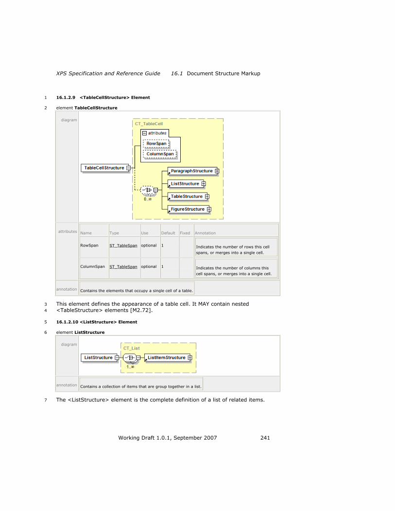
XPS Specification and Reference Guide 16.1 Document Structure Markup
Working Draft 1.0.1, September 2007 241
16.1.2.9 <TableCellStructure> Element 1
element TableCellStructure 2
diagram
attributes Name Type Use Default Fixed Annotation
RowSpan ST_TableSpan optional 1 Indicates the number of rows this cell
spans, or merges into a single cell.
ColumnSpan ST_TableSpan optional 1 Indicates the number of columns this
cell spans, or merges into a single cell.
annotation Contains the elements that occupy a single cell of a table.
This element defines the appearance of a table cell. It MAY contain nested 3
<TableStructure> elements [M2.72]. 4
16.1.2.10 <ListStructure> Element 5
element ListStructure 6
diagram
annotation Contains a collection of items that are group together in a list.
The <ListStructure> element is the complete definition of a list of related items. 7

16.1 Document Structure Markup Document Structure and Interactivity
242 Working Draft 1.0.1, September 2007
16.1.2.11 <ListItemStructure> Element 1
element ListItemStructure 2
diagram
attributes Name Type Use Default Fixed Annotation
Marker ST_NameUnique optional The named element that represents the
marker for this list items, such as a bullet,
number, or image.
annotation Describes a single structural block. These structural blocks are grouped together in a list.
A <ListItemStructure> element defines a single item in a list. 3
16.1.2.12 <FigureStructure> Element 4
element FigureStructure 5
diagram
annotation Groups the named elements that constitute a single drawing or diagram.
A <FigureStructure> element includes a group of named elements that comprise a 6
single drawing or diagram. 7

XPS Specification and Reference Guide 16.2 Hyperlinks
Working Draft 1.0.1, September 2007 243
16.1.2.13 <NamedElement> Element 1
element NamedElement 2
diagram
attributes Name Type Use Default Fixed Annotation
NameReference ST_Name required Identifies the named element in the
FixedPage part markup that is referenced
by the document structure markup.
annotation All document structure is related to the fixed page markup using this element. The
<NamedElement> points to a single markup element contained in the fixed page markup.
A <NamedElement> references a specific element in the fixed page by using the 3
NameReference attribute to specify an element in the fixed page markup with a 4
corresponding name. 5
If the targeted fixed page uses markup compatibility markup that changes the 6
presence of certain named elements, the StoryFragments part should also use it in 7
order to reference each element in either representation. 8
16.2 Hyperlinks 9
If consumers enable user interactivity, they SHOULD support hyperlink activation 10
and addressing [S9.6]. 11
16.2.1 Hyperlink Activation 12
Hyperlinks are specified inline on any <Canvas>, <Path>, or <Glyphs> element by 13
means of the FixedPage.NavigateUri attribute. The value of the attribute is the 14
destination URI. If hyperlinked <Path> or <Glyphs> elements are rendered as 15
overlapping on the page, consumers MUST treat the topmost element as the only 16
hyperlink that may be activated in the overlapping region [M9.2]. 17
When activating a hyperlink, consumers SHOULD load the specified resource if they 18
understand the URI type. If the URI is an internal reference to the XPS Document, 19
consumers SHOULD navigate to the URI [S9.7]. 20
If a producer specifies a FixedPage.NavigateUri attribute on a <Canvas> element, 21
consumers MUST treat all child elements of that canvas as having an associated 22
hyperlink [M9.3]. Child or descendant elements can override this value with their 23
own FixedPage.NavigateUri attribute. 24

16.2 Hyperlinks Document Structure and Interactivity
244 Working Draft 1.0.1, September 2007
Relative internal hyperlinks between FixedPage parts MUST specify, at a minimum, 1
the named address relative to the FixedDocument part [M9.4]. 2
Producers can mark any <FixedPage>, <Canvas>, <Path>, or <Glyphs> element as 3
an addressable location within the XPS Document by specifying a value for the 4
Name attribute. The name SHOULD be unique within the scope of the fixed 5
document [S9.8]. If it is not unique, only the first occurrence of the named address 6
is addressable. 7
These elements, if specified as a <VisualBrush.Visual> property element are not 8
addressable by a hyperlink. 9
It is RECOMMENDED that Name attribute values be unique within an entire fixed 10
document sequence [S9.9]. If they are not, only the first occurrence of the named 11
address is addressable from an external location. Internal hyperlinks can specify a 12
named element fragment relative to a particular fixed document, but consumers MAY 13
interpret such a URI relative to the entire fixed document sequence instead [O9.6]. 14
In order to be addressable by either a hyperlink or the document outline, the named 15
address MUST appear in the <PageContent.LinkTargets> element in the fixed 16
document [M9.5]. If a named address appears in the <PageContent.LinkTargets> 17
element in the fixed document but is not found in the Name attribute of an element 18
within the associated fixed page, consumers MUST treat the top of the associated 19
fixed page as the named address [M9.6]. If the named address in a URI fragment is 20
not found, consumers MUST ignore the fragment portion of the URI [M9.7]. 21
Example 16–8. A relative, internal, named-address hyperlink 22
FixedPage.NavigateUri="../MyDocument.fdoc#MyAddress" 23
end example] 24
16.2.2 Hyperlink Addressing 25
XPS Documents specify two forms of URI fragment identifiers to address locations 26
within an XPS Document. The first is a named address. [Example: 27
―http://xps/MyPackage#MyAddress‖, where ―http://xps/MyPackage‖ is an XPS 28
Document and ―MyAddress‖ is a named address within the document. end example] 29
The second is an absolute page number within the XPS Document. [Example: 30
―http://xps/MyPackage#15‖, where ―15‖ references the FixedPage part associated 31
with the fifteenth <PageContent> entry among all the fixed documents in the fixed 32
document sequence. end example] 33
Page number fragment identifiers refer to the absolute page number (1-based) in the 34
fixed document sequence. [Example: If an XPS Document has a 3-page fixed 35
document, followed by a 10-page fixed document, followed by an 8-page fixed 36
document, the fragment identifier ―#15‖ refers to the second page of the third fixed 37
document in the fixed document sequence. end example] Internal references MUST 38
specify a page address relative to the fixed document sequence [M9.8]. 39
Example 16–9. A relative internal page address hyperlink 40
FixedPage.NavigateUri="../../../MyDocSeq.fdseq#12" 41
end example] 42

XPS Specification and Reference Guide 16.2 Hyperlinks
Working Draft 1.0.1, September 2007 245
16.2.3 Name Attribute 1
The Name attribute contains a string value that identifies the current element as a 2
named, addressable point for the purpose of hyperlinking. The Name attribute is 3
optional. Names SHOULD be unique within a fixed document [S9.8], and it is 4
RECOMMENDED that they be unique within a fixed document sequence [S9.9]. The 5
Name attribute MUST NOT be specified on any children of a <ResourceDictionary> 6
element [M9.10]. 7
If the Name attribute is specified, producers SHOULD also create a corresponding 8
<LinkTarget> element in the FixedDocument part within the <PageContent> 9
element that links to the parent fixed page [S9.10]. Consumers MAY ignore this 10
attribute [O9.7], but devices that support user interaction with the contents of XPS 11
Documents SHOULD support hyperlinks [S9.6]. 12
The Name value, if specified, MUST meet the following requirements [M2.72]: 13
1. The initial character MUST be an underscore character or a letter, that is, it 14
falls within the Lu, Ll, Lo, Lt, and Nl categories [M2.72]. 15
2. Trailing characters MUST be an underscore character or a letter or number, 16
that is, they fall within the Lu, Ll, Lo, Lt, Nl, Mn, Mc, and Nd categories 17
[M2.72]. 0. 18
[Note: These requirements match those of XML identifiers with additional 19
restrictions. end note] 20
The category abbreviations, as defined within the Unicode Character Database, are 21
partially reproduced in Table 16–2. 22
Table 16–2. Unicode character categories 23
Abbreviation Description
Lu Letter, uppercase
Ll Letter, lowercase
Lt Letter, titlecase
Lo Letter, other
Mn Mark, non-spacing
Mc Mark, spacing combining
Nd Number, decimal
Nl Number, letter
16.2.4 FixedPage.NavigateUri Attribute 24
The FixedPage.NavigateUri attribute associates a hyperlink URI with an element, 25
making it a hyperlink source. Its value may be a relative or absolute URI that 26
addresses a resource that is internal or external to the XPS Document package, 27
respectively. The base URI used to resolve a relative URI is that of the FixedPage 28
part in which the element with the FixedPage.NavigateUri attribute appears. 29
Therefore, a hyperlink to a destination within the fixed document of the source MUST 30
specify the destination in the context of the FixedDocument part [M9.4]. [Example: 31
―../FixedDoc1.fdoc#MyDestination‖. end example] A destination in the same fixed 32
document SHOULD be expressed as a relative URI [S9.11]. 33

16.3 Selection Document Structure and Interactivity
246 Working Draft 1.0.1, September 2007
The FixedPage.NavigateUri attribute is OPTIONAL [M2.72]. It SHOULD be included 1
only if the element is intended to be a hyperlink. Consumers MAY ignore this 2
attribute [O9.8], but devices that support user interaction with the contents of XPS 3
Documents SHOULD support hyperlinks [S9.6]. 4
16.3 Selection 5
Viewing consumers that support interactivity MAY support selection and copying 6
[O9.9]. If selection is supported, consumers SHOULD provide a visual cue over or 7
around selected elements [S9.12]. Selection order within an XPS Document SHOULD 8
follow reading order [S9.13]. 9
Consumers MAY use the FragmentType attribute of the <StoryFragment> element 10
to determine selection behavior, such as disallowing selection of both the page 11
header and the page contents while allowing independent selection within those 12
stories [O9.10]. 13
16.4 Accessibility 14
Accessibility refers to features that are important to provide equal access to XPS 15
Documents for users of all abilities. One common example of an accessibility 16
application is a screen reader, which reads the contents of a document aloud for 17
vision-impaired individuals. 18
16.4.1 Reading Order 19
In the absence of document structure information provided in the XPS Document, 20
consumers MAY infer the reading order from the position of elements on the page 21
[O9.11], but SHOULD, at minimum, rely on the markup order to determine reading 22
order [S9.14]. Producers SHOULD order the markup in FixedPage parts to reflect the 23
order in which it is intended to be read [S9.15]. When document structure 24
information is present, consumers SHOULD rely on the order of appearance of 25
named elements in the content structure markup to determine reading order 26
[S9.16]. 27
The RECOMMENDED reading order of a page-centric application is as follows [S9.17]: 28
Order the content by page. 29
Within a page, order by story fragment in the order the <StoryFragment> 30
elements are specified in the StoryFragments part for that page. Producers 31
SHOULD order <StoryFragment> elements in their intended reading order 32
[S9.18]. 33
Within a <StoryFragment> element, order by <NamedElement> reference. 34
Append all un-referenced elements that appear in the fixed page markup, 35
ordered by markup order. 36
Although producers SHOULD reference every element of the fixed page markup in 37
the content structure markup [S9.10], consumers MUST expose every element of the 38
fixed page markup to an accessibility interface in the determined reading order, even 39
if the elements are not referenced in the content structure markup [M9.9]. 40

XPS Specification and Reference Guide 16.4 Accessibility
Working Draft 1.0.1, September 2007 247
Consumers MAY use the FragmentType attribute of the <StoryFragment> element 1
to determine reading order by interpreting elements that have FragmentType 2
values of Header and Footer as belonging first or last in the reading order, 3
respectively [O9.12]. 4
The RECOMMENDED reading order of a story-centric application is as follows 5
[S9.19]: 6
Order content by story in the sequence the <Story> elements appear in the 7
DocumentStructure part. Producers SHOULD order <Story> elements in their 8
intended reading order [S9.20]. 9
Within a story, order <StoryFragmentReference> elements in the sequence 10
they appear in the DocumentStructure part. Producers SHOULD order 11
<StoryFragmentReference> elements in their intended reading order [S9.21]. 12
Within a story fragment, order by <NamedElement> references in the 13
StoryFragments part markup. 14
Append all un-referenced elements that appear in the fixed page markup, 15
ordered by page number, then markup order. 16
16.4.2 Screen Reader Applications 17
Screen reader applications read the contents of the document aloud. A screen reader 18
consumer SHOULD read the document according to its reading order [S9.22]. The 19
application SHOULD use the UnicodeString attribute of each <Glyphs> element 20
[S9.23]. In addition, screen readers MAY inspect the Indices attribute to resolve 21
potential ambiguities [O9.13]. 22
If the screen reader provides features to navigate the document by structural 23
elements, such as paragraphs or table rows, it SHOULD use any document structure 24
information included in the XPS Document [S9.24]. 25
If the screen reader provides features to describe images, it SHOULD read the text 26
provided in the AutomationProperties.Name and 27
AutomationProperties.HelpText attributes [S9.25]. 28
If the screen reader provides features to describe hyperlink addresses, it SHOULD 29
read the text provided in the FixedPage.NavigateUri attribute [S9.26]. 30
16.4.3 Text Alternatives for Graphics and Images 31
Images and graphics SHOULD specify text alternatives for images and graphics to 32
make this content accessible to vision-impaired individuals [S9.27]. There are short 33
and long textual descriptions, specified in the AutomationProperties.Name and 34
AutomationProperties.HelpText attributes of <Path> and <Canvas>, 35
respectively. 36
The AutomationProperties.Name attribute SHOULD contain a short description of 37
the basic contents of the image or vector graphic [S9.27]. [Example: ―A sitting dog.‖ 38
end example]The AutomationProperties.HelpText attribute can contain a more 39
detailed description of the image or graphic. [Example: ―A cocker spaniel with brown 40
eyes, golden fur, and its tongue hanging out. It is sitting on a beanbag directly facing 41
the camera.‖ end example] 42

16.4 Accessibility Document Structure and Interactivity
248 Working Draft 1.0.1, September 2007
An image SHOULD specify the AutomationProperties.Name and 1
AutomationProperties.HelpText attributes on the <Path> element that is filled 2
with an <ImageBrush> [S9.28]. These attributes describe the content specified by 3
the ImageSource attribute of the <ImageBrush> element. 4
A vector graphic (a collection of one or more <Path> elements representing a single 5
drawing) SHOULD specify the AutomationProperties.Name and 6
AutomationProperties.HelpText attributes only once, directly on a <Canvas> 7
element wrapping the <Path> elements comprising the graphic [S9.29]. 8
Individual <Path> elements that do not provide any semantic meaning (such as a 9
line between sections or outlining a table) SHOULD NOT specify these text 10
alternative attributes [S9.27]. 11
12

XPS Specification and Reference Guide 17.1 Interleaving Optimizations
Working Draft 1.0.1, September 2007 249
17. XPS Document Package Features 1
The XPS Document format extends package-level interleaving and digital signatures 2
as described in the OPC specification. 3
17.1 Interleaving Optimizations 4
Interleaving concerns the physical organization of XPS Documents, rather than their 5
logical structure. It allows consumers to linearly process the bytes that make up a 6
physical package from start to finish, without regard for context. In other words, 7
consumers can make correct determinations about the types of logical parts and the 8
presence of relationships on a logical part when consuming packages in a linear 9
fashion. Consumers are never required to return to previously encountered parts and 10
revise their determination of the content type or presence of relationships. 11
Interleaving is OPTIONAL [O10.1]. However, if the XPS Document is interleaved, 12
these rules SHOULD be followed: 13
The Content Types stream SHOULD be interleaved according to the 14
recommendations in the OPC specification [S10.1]. 15
PrintTicket parts SHOULD be written to the package before the part to which 16
they are attached [S10.2]. 17
The portion of the relationship data attaching the PrintTicket to a part SHOULD 18
be written to the package before the part to which it is attached or in close 19
proximity to the part to which it is attached [S10.3]. 20
If no PrintTicket settings are specified for a FixedDocumentSequence, 21
FixedDocument, or FixedPage part, an empty PrintTicket part SHOULD be 22
attached to the part, and the portion of the relationship data attaching the 23
empty PrintTicket SHOULD be written to the package before the part to which 24
it is attached or in close proximity to the part to which it is attached [S10.4]. 25
The last piece of the Relationships part for a FixedPage part SHOULD be 26
written to the package in close proximity to the first piece of the FixedPage 27
part [S10.5]. 28
Following these recommendations allows more efficient processing by certain 29
consumers. Not following these recommendations could result in less efficient 30
processing by most consumers because they will need to wait until all parts required 31
to process a part (attached PrintTicket, required resources) have been consumed. 32
However, consumers MUST be prepared to correctly process packages in which the 33
PrintTicket or the portion of the relationship data attaching the PrintTicket appears in 34
the package after the affected part [M10.1]. 35
Consumers can choose to parse an XPS Document in a head-first or tail-first manner. 36
Tail-first parsing reveals certain package errors earlier, such as inconsistencies 37
between the ZIP central directory and local file headers. Head-first XPS Document 38
consumers SHOULD attempt to detect inconsistent packages as soon as possible and 39
SHOULD generate an error message, even if they have already processed the pages 40
that resulted in the error [S10.18]. Head-first consumers that discard parts would 41

17.1 Interleaving Optimizations XPS Document Package Features
250 Working Draft 1.0.1, September 2007
need to retain the name and length of any discarded part to comply with this 1
recommendation. 2

XPS Specification and Reference Guide 17.1 Interleaving Optimizations
Working Draft 1.0.1, September 2007 251
17.1.1 Empty PrintTicket 1
An empty PrintTicket has the following form: 2
<psf:PrintTicket 3
xmlns:psf="http://schemas.microsoft.com/windows/2003/08/printing/printsch4
emaframework" version="1"/> 5
It is RECOMMENDED that one empty PrintTicket be shared for all parts that attach an 6
empty PrintTicket [S10.6]. 7
17.1.2 Optimizing Interleaving Order 8
Producers MAY optimize the interleaving order of parts to help consumers avoid stalls 9
during read-time streaming, and to allow consumers to manage their memory 10
resources more efficiently [O10.2]. 11
The optimization strategy is suggested by the consumer architecture. Therefore, 12
interleaving optimization is typically implemented by a software component such as 13
a driver or filter that is specific to (or aware of) the consumer architecture. 14
17.1.2.1 Single-Threaded Parsing Architectures 15
An optimal interleaving scheme for consumers with a single-threaded parsing model 16
interleaves parts so that each part that is required to consume a single page 17
(FixedPage, images, and fonts) is contained in the package in its entirety, prior to 18
the FixedPage part being referenced from the FixedDocument part‘s markup. 19
Single-threaded parsing architectures typically require more run-time memory 20
resources than multi-threaded parsing architectures because the context in which a 21
resource is used is unknown at the time the resource is received. This requires 22
deferred processing and additional buffering. 23
[Note: When interleaving entities containing XML markup, such as the DiscardControl 24
part, the Content Types stream, and the FixedDocument part, there is no guarantee 25
that XML element boundaries will align with piece boundaries in the physical 26
package. This adds a complexity to single-threaded parsing architectures: the parser 27
must be pre-emptable. Certain existing XML parser implementations may require a 28
pre-tokenization step. end note] 29
Example 17–1. Optimized interleaving for a single-threaded parsing architecture 30
The following markup describes a sequence of two fixed documents, the first having 31
two FixedPage parts and the second having one FixedPage part: 32
33
Part/Piece Markup
Font1.ttf ...binary font data...
Other resources ...resource data...
Page1 <FixedPage xmlns="http://schemas.microsoft.com
/xps/2005/06" ...>
<Glyphs FontURI="Font1.ttf"/>
</FixedPage>
Page1.rels <Relationships xmlns=

17.1 Interleaving Optimizations XPS Document Package Features
252 Working Draft 1.0.1, September 2007
"http://schemas.openxmlformats.org/package/2006/re
lationships">
<Relationship Type=
"http://schemas.microsoft.com/xps/2005/06
/required-resource" Target="Font1.ttf"/>
</Relationships>
FixedDocument1/[0].piece <FixedDocument xmlns=
"http://schemas.microsoft.com/xps/2005/06">
<PageContent Source="Page1"/>
Sequence1/[0].piece <FixedDocumentSequence xmlns=
"http://schemas.microsoft.com/xps/2005/06">
<DocumentReference Source="FixedDocument1"/>
_rels/.rels/[0].piece <Relationships xmlns=
"http://schemas.openxmlformats.org/package/2006/re
lationships">
<Relationship Type="StartPart" Target="Sequence1"/>
Page2 <FixedPage xmlns=
"http://schemas.microsoft.com/xps/2005/06"
...>...</FixedPage>
FixedDocument1/[1].last.piece
<PageContent Source="Page2"/>
</FixedDocument>
Page3 <FixedPage xmlns=
"http://schemas.microsoft.com/xps/2005/06"
...>...</FixedPage>
FixedDocument2 <FixedDocument xmlns=
"http://schemas.microsoft.com/xps/2005/06">
<PageContent Source="Page3"/>
</FixedDocument>
Sequence1/[1].last.piece <DocumentReference Source="FixedDocument2" />
</FixedDocumentSequence>
_rels/.rels/[1].last.piece </Relationships>
end example] 1
17.1.2.2 Multi-Threaded Parsing Architectures 2
An optimal interleaving scheme for consumers with a multi-threaded parsing model 3
interleaves parts so that each resource part that is required to consume a single 4
page (images and fonts) is contained in the package after the FixedPage part 5
referencing it. 6
Multi-threaded parsing architectures typically require less run-time memory 7
resources than single-threaded parsing architectures because the context in which 8
resources appear is fully determined and, therefore, resources can be processed 9
immediately. 10
[Note: When interleaving entities containing XML markup, such as the DiscardControl 11
part, the content type stream, and the FixedDocument part, there is no guarantee 12
that XML element boundaries will align with piece boundaries in the physical 13

XPS Specification and Reference Guide 17.1 Interleaving Optimizations
Working Draft 1.0.1, September 2007 253
package. A multi-threaded parsing architecture is naturally suited to address this 1
problem. end note] 2

17.1 Interleaving Optimizations XPS Document Package Features
254 Working Draft 1.0.1, September 2007
Example 17–2. Optimized interleaving for a multi-threaded parsing architecture 1
The following markup describes a sequence of two FixedDocument parts, the first 2
having two FixedPage parts and the second having one FixedPage part: 3
4
Part/Piece Markup
_rels/.rels/[0].piece <Relationships
xmlns="http://schemas.microsoft.com/package
/2005/06/relationships">
<Relationship Type="StartPart" Target=
"Sequence1"/>
Sequence1/[0].piece <FixedDocumentSequence xmlns=
"http://schemas.microsoft.com/xps/2005/06">
<DocumentReference Source="FixedDocument1"/>
FixedDocument1/[0].piece <FixedDocument xmlns=
"http://schemas.microsoft.com/xps/2005/06">
<PageContent Source="Page1"/>
Page1.rels <Relationships xmlns=
"http://schemas.openxmlformats.org/package/2006/re
lationships">
<Relationship Type=
"http://schemas.microsoft.com/xps/2005/06
/required-resource" Target="Font1.ttf"/>
</Relationships>
Page1 <FixedPage ="http://schemas.microsoft.com
/xps/2005/06" ...>
<Glyphs FontURI="Font1.ttf"/>
</FixedPage>
Font1.ttf ...binary font data...
Other resources ...resource data...
FixedDocument1/[1].last.pi
ece
<PageContent Source="Page2"/>
Page2 <FixedPage xmlns=
"http://schemas.microsoft.com/xps/2005/06"
...>...</FixedPage>
FixedDocument1/[2].last.piece
</FixedDocument>
Sequence1/[1].last.piece <DocumentReference Source="FixedDocument2" />
</FixedDocumentSequence>
FixedDocument2 <FixedDocument xmlns=
"http://schemas.microsoft.com/xps/2005/06">
<PageContent Source="Page3"/>
</FixedDocument>
Page3 <FixedPage
xmlns="http://schemas.microsoft.com/xps/2005/06"

XPS Specification and Reference Guide 17.1 Interleaving Optimizations
Working Draft 1.0.1, September 2007 255
...>...</FixedPage>
_rels/.rels/[1].last.piece </Relationships>
end example] 1
17.1.3 Consuming Interleaved Packages 2
Consumers MUST be able to consume packages regardless of their interleaving 3
structure [M10.2]. Consumers that lack the resources to process a part MUST 4
indicate an error condition [M10.3]. Such a resource constraint exists when a 5
consumer lacks sufficient memory resources to hold enough of the package to 6
resolve all the references required to process a part. 7
To address resource constraints: 8
Consumers MAY discard FixedPage parts once they have been processed 9
[O10.3] 10
Consumers MAY discard FixedDocument and FixedDocumentSequence parts 11
after all their child elements and their closing tags have been processed 12
[O10.4]. 13
In the absence of explicit directives to the contrary (see §17.1.4, ―Consumers 14
with Resource Constraints,‖ below), consumers MAY discard parts as directed 15
by the DiscardControl part [O10.5]. Consumers MUST NOT discard any other 16
parts [Example: Such as parts containing fonts, images, or other resources 17
end example] unless they have the ability to access the parts again [M10.4]. 18
If a consumer encounters a reference to an unknown part, it MUST continue to 19
receive further bytes of the package until the unknown part has been transmitted or 20
until the end of the package is reached (indicating an error condition) [M10.5]. 21
17.1.4 Consumers with Resource Constraints 22
To produce an XPS Document for streaming consumption by consumers with limited 23
memory resources, some producers MAY choose a suitable interleaving order by 24
modeling the resource management behavior of the consumer [O10.6]. These 25
producers, referred to as drivers, must have specific knowledge of the XPS 26
Document consumer. Due to resource constraints, some consumers are unable to 27
consume arbitrary XPS Documents and always require assistance from an external 28
driver. 29
When some consumers with limited memory resources receive a XPS Document in a 30
streaming fashion, there might be an opportunity to discard parts when necessary 31
and reload them again when needed. Producers, such as drivers, that target such 32
consumers SHOULD follow these steps [S10.7]: 33
Conservatively model the memory usage of the device. 34
Interleave pieces of parts in the correct order. 35
Decide when certain parts can be discarded by the consumer and inform the 36
consumer within the package stream (see §17.1.4.1, ―DiscardControl Part,‖ 37
below). 38
Add to the package a uniquely named copy of a resource that could have been 39
discarded, if the resource is referenced by a part sent later in the stream. 40

17.1 Interleaving Optimizations XPS Document Package Features
256 Working Draft 1.0.1, September 2007
Those later references are also updated to refer to the new copy of the 1
resource. 2
17.1.4.1 DiscardControl Part 3
In addition to optimally ordering interleaved parts, producers may support 4
consumers with resource constraints by means of the DiscardControl part. The 5
DiscardControl part is a well-known part containing a list of resources that are safe 6
for the consumer to discard. DiscardControl parts are stored in XPS Documents in an 7
interleaved fashion, allowing a resource-constrained consumer to discard a part as 8
soon as it appears in the DiscardControl part. DiscardControl parts are targeted with 9
a DiscardControl package relationship, as specified in H, ―Standard Namespaces and 10
Content Types.‖ There MUST NOT be more than one DiscardControl package 11
relationship [M10.23]. The DiscardControl part MUST NOT reference itself [M10.6]; 12
doing so is considered an error. 13
DiscardControl parts that are not well-formed SHOULD NOT be processed and an 14
error SHOULD NOT be reported [S10.8]. The consumer MAY decide to ignore the 15
malformed DiscardControl part in its entirety or from the first malformed node 16
onward [O10.7]. 17
In some cases, producers might rewrite the contents of a package so that parts are 18
provided more than once, allowing consumers to discard a part in order to free 19
resources for additional processing. Each instance of a part MUST be stored as a 20
new, uniquely named part in the package [M10.24]. 21
Example 17–3. A DiscardControl part 22
<DiscardControl xmlns="http://schemas.microsoft.com/xps/2005/06/discard- 23
control"> 24
<!-- May discard partname1 as soon as starting to process 25
page11.xaml --> 26
<Discard SentinelPage="/page11.xaml" Target="/partname1" /> 27
<!-- May discard partname2 as soon as starting to process 28
page13.xaml --> 29
<Discard SentinelPage="/page13.xaml" Target="/partname2" /> 30
... 31
</DiscardControl> 32
end example] 33
17.1.4.1.1 <DiscardControl> Element 34
element DiscardControl 35
diagram
annotation Contains a list of resources that are safe for a consumer to discard.
17.1.4.1.2 <Discard> Element 36
element Discard 37

XPS Specification and Reference Guide 17.1 Interleaving Optimizations
Working Draft 1.0.1, September 2007 257
diagram
attributes Name Type Use Default Fixed Annotation
SentinelPage xs:anyURI required The first fixed page that no longer needs the
identified resource in order to be processed.
Target xs:anyURI required The resource that can be safely discarded.
annotation Identifies a resource that can be safely discarded by a resource-constrained consumer.
Parts that can be discarded are identified in a <Discard> element by the Target 1
attribute value, which is expressed as relative to the package root, and by the 2
SentinelPage attribute value, which identifies the first FixedPage part that no longer 3
requires the discarded part. (The processing order for FixedPage parts is implied by 4
the order of <PageContent> element references in the FixedDocument part. 5
Therefore, the value of the SentinelPage attribute is unambiguous.) 6
If either the Target attribute or the SentinelPage attribute contain an invalid 7
reference (refer outside the package), the respective <Discard> element MUST be 8
ignored [M10.7]. If a <Discard> element is encountered where either or both of the 9
Target attribute and SentinelPage attribute identify a part which has not been 10
processed yet (is still unknown), the <Discard> element SHOULD be retained until 11
both parts identified by the Target attribute and SentinelPage attribute have been 12
processed or until the end of the package is reached [S10.9]. 13
17.1.5 Interleaving Optimizations and Digital Signatures 14
In general, it is not feasible to produce well-ordered, interleaved ZIP packages and 15
apply digital signatures in a way that enables reasonable consumption scenarios for 16
the following reasons: 17
The digital signature parts must be known to consumers before they process 18
other signed parts because the selected hash-methods and transforms must 19
be known. A streaming consumer might not be able to access part data after it 20
has been processed for printing. 21
Producers cannot create the digital signature parts before producing the 22
signed packages. 23
There are cyclic dependencies with signed relationship parts containing the 24
relationship to the signature parts themselves. 25
Therefore, when adding a digital signature to an interleaved package, producers of 26
digitally signed documents that are intended for streaming consumption SHOULD 27
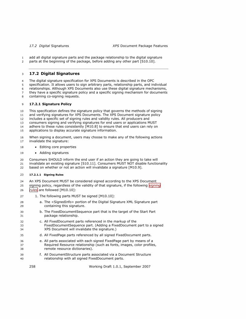
17.2 Digital Signatures XPS Document Package Features
258 Working Draft 1.0.1, September 2007
add all digital signature parts and the package relationship to the digital signature 1
parts at the beginning of the package, before adding any other part [S10.10]. 2
17.2 Digital Signatures 3
The digital signature specification for XPS Documents is described in the OPC 4
specification. It allows users to sign arbitrary parts, relationship parts, and individual 5
relationships. Although XPS Documents also use these digital signature mechanisms, 6
they have a specific signature policy and a specific signing mechanism for documents 7
containing co-signing requests. 8
17.2.1 Signature Policy 9
This specification defines the signature policy that governs the methods of signing 10
and verifying signatures for XPS Documents. The XPS Document signature policy 11
includes a specific set of signing rules and validity rules. All producers and 12
consumers signing and verifying signatures for end users or applications MUST 13
adhere to these rules consistently [M10.8] to ensure that end users can rely on 14
applications to display accurate signature information. 15
When signing a document, users may choose to make any of the following actions 16
invalidate the signature: 17
Editing core properties 18
Adding signatures 19
Consumers SHOULD inform the end user if an action they are going to take will 20
invalidate an existing signature [S10.11]. Consumers MUST NOT disable functionality 21
based on whether or not an action will invalidate a signature [M10.9]. 22
17.2.1.1 Signing Rules 23
An XPS Document MUST be considered signed according to the XPS Document 24
signing policy, regardless of the validity of that signature, if the following signing 25
rules are followed [M10.10]: 26
1. The following parts MUST be signed [M10.10]: 27
a. The <SignedInfo> portion of the Digital Signature XML Signature part 28
containing this signature. 29
b. The FixedDocumentSequence part that is the target of the Start Part 30
package relationship. 31
c. All FixedDocument parts referenced in the markup of the 32
FixedDocumentSequence part. (Adding a FixedDocument part to a signed 33
XPS Document will invalidate the signature.) 34
d. All FixedPage parts referenced by all signed FixedDocument parts. 35
e. All parts associated with each signed FixedPage part by means of a 36
Required Resource relationship (such as fonts, images, color profiles, 37
remote resource dictionaries). 38
f. All DocumentStructure parts associated via a Document Structure 39
relationship with all signed FixedDocument parts. 40

XPS Specification and Reference Guide 17.2 Digital Signatures
Working Draft 1.0.1, September 2007 259
g. All StoryFragments parts associated via Story Fragments relationship with 1
all signed FixedPage parts. 2
h. All SignatureDefinitions parts associated via a Signature Definitions 3
relationship with any signed FixedDocument part. (Once a document is 4
signed, adding any new signature definitions will invalidate the signature.) 5
i. All Thumbnail parts associated via a Thumbnail relationship from the 6
package root or with any signed FixedPage or FixedDocument part. . 7
2. The following parts MAY be signed [M10.10]: 8
a. The CoreProperties part. 9
b. The Digital Signature Origin part. 10
c. A Digital Signature Certificate part. 11
d. PrintTicket parts. 12
e. DiscardControl parts. . 13
3. All relationships with the following RelationshipTypes (see H, ―Standard 14
Namespaces and Content Types‖) MUST be signed [M10.10]: 15
a. StartPart relationship from the package root 16
b. DocumentStructure relationship from a FixedDocument part 17
c. StoryFragments relationship from a FixedPage part 18
d. Digital Signature Definitions relationship from a FixedDocument part 19
e. Required Resource relationship from a FixedPage part 20
f. Restricted Font relationship from a FixedDocument part 21
g. Thumbnail relationship from a FixedPage part, a FixedDocument part, or 22
the package root . 23
4. All relationships with the following RelationshipTypes MUST be signed if their 24
Target part is signed [M10.10]: 25
a. Core Properties relationship 26
b. Digital Signature Origin relationship 27
c. Digital Signature Certificate relationship from a Digital Signature XML 28
Signature part 29
d. PrintTicket relationship 30
e. DiscardControl relationship . 31
5. Relationships with the following RelationshipTypes MAY be signed as a group 32
(they MUST NOT be signed individually) [M10.10]: 33
a. All Digital Signature XML Signature relationships from the Digital Signature 34
Origin part (signing all relationships of this RelationshipType will cause this 35
signature to break when a new signature is added). 36
6. All of the above-referenced parts and relationships MUST be signed using a 37
single digital signature [M10.10].0. 38
An XPS Document MUST NOT be considered signed according to the XPS Document 39
signing policy if [M10.11]: 40

17.2 Digital Signatures XPS Document Package Features
260 Working Draft 1.0.1, September 2007
1. Any part not covered by the signing rules above is included in the signature. 1
2. Any relationship not covered by the signing rules above is included in the 2
signature.0. 3
An XPS Document digital signer MUST NOT sign an XPS Document that contains 4
content (parts or relationships parts) to be signed that defines the Markup 5
Compatibility namespace but the signer does not fully understand all elements, 6
attributes, and alternate content representations introduced through the markup 7
compatibility mechanisms [M10.12]. An XPS Document digital signer MAY choose not 8
to sign any content (parts or relationships parts) that defines the Markup 9
Compatibility namespace, even if the content is fully understood [O10.8]. 10
17.2.1.2 Signing Validity 11
An XPS Document digital signature MUST be shown as an incompliant digital 12
signature if [M10.13]: 13
It violates any of the signing rules described above regarding parts or 14
relationships that MUST or MUST NOT be signed. 15
An XPS Document digital signature MUST be shown as a broken digital signature if 16
[M10.14]: 17
It is not an incompliant digital signature, but the signature fails the signature 18
validation routines described in the Open Packaging Conventions. 19
An XPS Document digital signature MUST be shown as a questionable digital 20
signature if any of the following are true [M10.15]: 21
It is not an incompliant or broken digital signature, but the certificate cannot 22
be authenticated against the certificate authority. 23
It is not an incompliant or broken digital signature, but the signed content 24
(parts and relationships) contain elements or attributes from an unknown 25
namespace introduced through the Markup Compatibility mechanisms. 26
An XPS Document digital signature MAY be shown as a questionable digital signature 27
if [O10.9]: 28
It is not an incompliant or broken digital signature, but contains some other 29
detectable problem at the discretion of the consumer. 30
An XPS Document digital signature MUST be shown as a valid digital signature if 31
[M10.16]: 32
It is not an incompliant, broken, or questionable digital signature. 33
17.2.1.3 Adding Signatures 34
XPS Documents MAY be signed more than once [O10.10]. A user who signs an XPS 35
Document might or might not want to allow any additional signing of the document. 36
To prohibit additional signatures in an XPS Document, the signing application MUST 37
sign all the Digital Signature Origin part‘s relationships of relationship type Digital 38
Signature with the same signature as the rest of the content [M10.17]. 39

XPS Specification and Reference Guide 17.2 Digital Signatures
Working Draft 1.0.1, September 2007 261
17.2.1.4 Certificate Store 1
XPS Document signatures MUST NOT refer to a remote certificate store (certificate 2
not contained in the XPS Document). All certificates MUST be stored in the XPS 3
Document either as a Certificate part or in the Digital Signature XML Signature part 4
[M10.18]. 5
17.2.1.5 Printing Signed Documents 6
When printing signed documents, the PrintTicket setting 7
JobDigitalSignatureProcessing SHOULD be used to control the digital signature 8
processing behavior [S10.12]. Producers MAY include the 9
JobDigitalSignatureProcessing setting in the job-level PrintTicket within the XPS 10
Document content [O10.11]. Consumers SHOULD process this PrintTicket setting, if 11
present [S10.12]. For more information, see the Print Schema specification. 12
Table 17–1. JobDigitalSignatureProcessing PrintTicket settings 13
Name Description
PrintInvalidSignatures Print the job regardless of the validity of the digital signatures. Digital signatures can be
ignored.
PrintInvalidSignaturesWithErrorReport Print the job regardless of the validity of the digital signatures. In the event an invalid
signature is encountered, an error page
should print at the end of the job. Digital signatures cannot be ignored.
PrintOnlyValidSignatures Print the job only if all digital signatures are
valid. Digital signatures cannot be ignored.
17.2.2 Signature Definitions 14
In some workflow scenarios, documents must be signed as a means of approving 15
their content. [Example: Document producers may be required to sign their 16
documents in order to provide proof of authenticity. end example] In other cases, 17
reviewers may be required to co-sign content before it can be submitted for 18
publication. These requirements can be fulfilled with a digitally signed XPS 19
Document. 20
Whereas the XPS package model supports the signing of arbitrary content in a 21
package, an XPS Document signing workflow requires additional features, including 22
the ability to specify co-signature requirements and to include workflow-specific 23
signature information in the document. XPS Document authors and signing parties 24
provide such information in an XML signature definition. 25
Signature definitions are represented by <SignatureDefinition> elements within a 26
single <SignatureDefinitions> element. 27

17.2 Digital Signatures XPS Document Package Features
262 Working Draft 1.0.1, September 2007
Example 17–4. A SignatureDefinitions part 1
<SignatureDefinitions xmlns="http://schemas.microsoft.com/xps/2005/06/ 2
signature-definitions"> 3
<SignatureDefinition SignerName="Dorena Paschke" SpotID="AE2351H"> 4
<SpotLocation 5
PageURI="/Documents/1/Pages/2.fpage" 6
StartX="0.0" 7
StartY="0.0" /> 8
<Intent>I have read and agree<Intent> 9
<SignBy>2005-08-20</SignBy> 10
<SigningLocation>Redmond, WA</SigningLocation> 11
<SignatureDefinition> 12
</SignatureDefinitions> 13
end example] 14
17.2.2.1 <SignatureDefinitions> Element 15
element SignatureDefinitions 16
diagram
annotation The root element for the SignatureDefinitions part.
If the SignatureDefinitions part exists, it MUST contain only one 17
<SignatureDefinitions> element [M2.72]. The XML namespace for the 18
<SignatureDefinitions> element is specified in §H.1, ―XML Namespace URIs,‖ on 19
page 405. 20
17.2.2.2 <SignatureDefinition> Element 21
element SignatureDefinitionsType/SignatureDefinition 22
diagram
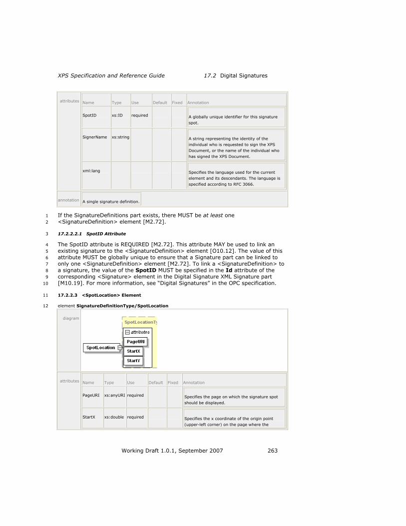
XPS Specification and Reference Guide 17.2 Digital Signatures
Working Draft 1.0.1, September 2007 263
attributes Name Type Use Default Fixed Annotation
SpotID xs:ID required A globally unique identifier for this signature
spot.
SignerName xs:string A string representing the identity of the
individual who is requested to sign the XPS
Document, or the name of the individual who
has signed the XPS Document.
xml:lang Specifies the language used for the current
element and its descendants. The language is
specified according to RFC 3066.
annotation A single signature definition.
If the SignatureDefinitions part exists, there MUST be at least one 1
<SignatureDefinition> element [M2.72]. 2
17.2.2.2.1 SpotID Attribute 3
The SpotID attribute is REQUIRED [M2.72]. This attribute MAY be used to link an 4
existing signature to the <SignatureDefinition> element [O10.12]. The value of this 5
attribute MUST be globally unique to ensure that a Signature part can be linked to 6
only one <SignatureDefinition> element [M2.72]. To link a <SignatureDefinition> to 7
a signature, the value of the SpotID MUST be specified in the Id attribute of the 8
corresponding <Signature> element in the Digital Signature XML Signature part 9
[M10.19]. For more information, see ―Digital Signatures‖ in the OPC specification. 10
17.2.2.3 <SpotLocation> Element 11
element SignatureDefinitionType/SpotLocation 12
diagram
attributes Name Type Use Default Fixed Annotation
PageURI xs:anyURI required Specifies the page on which the signature spot
should be displayed.
StartX xs:double required Specifies the x coordinate of the origin point
(upper-left corner) on the page where the

17.2 Digital Signatures XPS Document Package Features
264 Working Draft 1.0.1, September 2007
signature spot should be displayed.
StartY xs:double required Specifies the y coordinate of the origin point
(upper-left corner) on the page where the
signature spot should be displayed.
annotation Specifies where a consumer should place a signature spot.
The <SpotLocation> element is OPTIONAL [M2.72]. It specifies where an XPS 1
Document viewer should place a visual representation or signature spot to indicate 2
that a digital signature has been applied or requested. The viewing consumer 3
SHOULD use the values specified in this element. Due to space and rendering 4
limitations, producers MUST NOT assume that consumers will use these values 5
[M10.20]. If the location specified by this element is not used, it is RECOMMENDED 6
that consumers choose a location that does not contain any page content [S10.13]. 7
The size and shape of the signature spot are determined by the consumer. 8
Consumers MAY choose a size and shape based on the desired display information 9
and page content [O10.13]. However, it is RECOMMENDED that they render 10
signature spots as consistently sized rectangles that include the signer name, the 11
intent, the signing location, and the scope of the XPS Document to be signed 12
[S10.14]. It is also RECOMMENDED that the signature spot be a clickable area used 13
to launch the digital signing process [S10.15]. 14
Figure 17–1. A sample signature spot 15
16
17.2.2.4 <Intent> Element 17
element SignatureDefinitionType/Intent 18
diagram
annotation A string that represents the intent to which the signing party agrees when signing the document.
Consumers MUST display the full value of the <Intent> element to the signing party, 19
either in the signature spot or through some other mechanism [M10.21]. 20
[Note: Consumers that wish to display signature spots must consider the implications 21
of supporting any Unicode character that can be specified in the <Intent> element. 22
They must also make decisions about the appropriate font face and size to use as 23
well as determine the proper layout and interactivity of the signature spot. These 24
decisions are implementation-specific. end note] 25

XPS Specification and Reference Guide 17.3 Core Properties
Working Draft 1.0.1, September 2007 265
17.2.2.5 <SignBy> Element 1
element SignatureDefinitionType/SignBy 2
diagram
annotation The date and time by which the requested party is to sign the XPS Document.
If specified, the consumer SHOULD NOT allow the signing party to sign the document 3
using this particular signature spot after the date and time specified [S10.16]. The 4
date and time MUST be specified as a complete date plus hours, minutes, and 5
seconds in UTC time, as described in the W3C Note ―Date and Time Formats‖ 6
[M10.22], [Example: ―2006-12-31T23:59:59Z‖ or 11:59 PM (UTC) on December 31, 7
2006. end example] 8
17.2.2.6 <SigningLocation> Element 9
element SignatureDefinitionType/SigningLocation 10
diagram
annotation The legal location where the document is signed.
The <SigningLocation> element MAY be set by the original producer of the XPS 11
Document or by the signing party at the time of signing [O10.14]. 12
17.3 Core Properties 13
XPS Documents use the Core Properties part described in the OPC. The core 14
properties specified in that part SHOULD refer to the entire fixed payload, including 15
the root FixedDocumentSequence part and the compilation of all FixedDocument 16
parts it references [S10.17]. 17


XPS Specification and Reference Guide18.1 Coordinate System and Rendering
Placement
Working Draft 1.0.1, September 2007 267
18. Rendering Rules 1
The set of rules described here ensures precise and consistent rendering of XPS 2
Document markup across various implementations. Producers MUST generate XPS 3
Documents that can be accurately rendered by following the rules described in this 4
clause [M11.1]. Consumers MUST adhere to the rules described in this clause when 5
rendering XPS Documents [M11.1]. In addition to rules for visual elements, 6
implementation limits are also discussed. 7
18.1 Coordinate System and Rendering Placement 8
In the x,y coordinate system, one unit is initially equal to 1/96", expressed as a real 9
number. The initial origin of the coordinate system is the top left corner of the fixed 10
page. The x-coordinate value increases from left to right; the y-coordinate value 11
increases from top to bottom. 12
A RenderTransform property can be specified on any path, glyphs, or canvas to apply 13
an affine transform to the current coordinate system. 14
A Transform property can be specified on any visual brush, image brush, linear 15
gradient brush, radial gradient brush, or path geometry to apply an affine transform 16
to the current coordinate system. 17
18.1.1 Page Dimensions 18
The logical page dimensions correspond to the media size specified in the application 19
page layout and are specified by the Width and Height attributes of the 20
<FixedPage> element. Further optional attributes on the <FixedPage> element are 21
used to specify details about the areas of the fixed page that contain rendered 22
content. For more information, see §10.3, ―<FixedPage> Element,‖ on page 53. 23
The physical page dimensions correspond to the media size specified for printing. 24
The physical page dimensions are specified in the PrintTicket PageMediaSize 25
keyword. 26
The interaction of the logical page dimensions and the physical page dimensions is 27
print-specific. For more information, see §10.3.3, ―Page Size Terminology,‖ 28
and §10.3.4, ―Media Orientation and Scaling.‖ 29
18.1.2 Rounding of Coordinates 30
All computations on coordinate values SHOULD be performed with at least single 31
floating-point precision [S11.1]. Final conversion (after all transforms have been 32
computed) to device coordinates SHOULD retain at least as much fractional precision 33
as a 28.4 fixed-point representation before performing pixel coverage calculations 34
[S11.1]. 35
Very high resolution devices MAY use lower fractional precision to represent device 36
coordinates [O11.1]. 37

18.1 Coordinate System and Rendering Placement Rendering Rules
268 Working Draft 1.0.1, September 2007
When converting from real-number coordinate values to device coordinate values, 1
rounding is performed according to the following rule: 2
coordD = ROUND(coordR*16.0)/16 3
Where coordR expresses a real-number coordinate value and coordD expresses a 4
device coordinate value. 5
18.1.3 Transforms 6
XPS Document markup supports affine transforms as expressed through the 7
RenderTransform and Transform properties. An affine transform is represented as a 8
list of six real numbers: m11, m12, m21, m22, dx, dy. (For markup details, 9
see §14.4, ―Positioning Content,‖ on page 185.) 10
The full matrix is as follows: 11
[
] m11 m12 0
m21 m22 0
dx dy 1
A given x,y coordinate is transformed with a render transform to yield the resulting 12
coordinate x′,y′ by applying the following computations: 13
x′ = x * m11 + y * m21 + dx 14
y′ = x * m12 + y * m22 + dy 15
When rendering a child or descendant element, the effective transform used for 16
rendering is the concatenation of all the transforms specified by the 17
RenderTransform or Transform property on parent or ancestor elements, starting 18
from the outermost ancestor. 19
Non-invertible effective transforms can be specified in markup or occur as a result of 20
limited numerical precision during concatenation. If a non-invertible transform is 21
encountered during rendering, consumers MUST omit rendering the affected element 22
and all of its child and descendant elements [M11.2]. 23
If a non-invertible transform is encountered on a brush (as specified directly on the 24
brush, as a result of the Viewbox or Viewport attributes, or through 25
concatenation), the brush is treated according to §18.7.1, ―Small Tiles,‖ on page 26
299. 27
The Width and Height values specified in the Viewbox and Viewport attributes of 28
an <ImageBrush> or <VisualBrush> element MUST NOT be negative [M2.72]. 29
If a non-invertible transform is encountered on a geometry (as specified directly on 30
the geometry or through concatenation), the geometry MUST be considered to 31
contain no area [M11.3]. 32
A final, device-dependent step using the horizontal resolution and vertical resolution 33
of the device converts the resulting coordinates x′,y′ to device coordinates x″,y″, as 34
follows: 35
x″ = x′ * RX/96 36
y″ = y′ * RY/96 37

XPS Specification and Reference Guide18.1 Coordinate System and Rendering
Placement
Working Draft 1.0.1, September 2007 269
Where RX is the horizontal resolution and RY is the vertical resolution of the device, 1
specified in device pixels per inch. 2
18.1.4 Pixel Center Location, Pixel Placement, and Pixel Inclusion 3
A pixel covers the range from x to x+1. 4
An ideal consumer implementation SHOULD render pixels in an 8x8 sub-pixel space, 5
perform an 8x8 box filter sampling, and set the pixel to the resulting color value 6
[S11.2]. Other implementations MAY use different rendering logic as long as it 7
closely approximates this logic [O11.2]. 8
When rendering a shape, a practical implementation (such as a bi-tonal printing 9
device) SHOULD turn on each pixel whose center (at x+0.5) is covered by the shape, 10
or is touched by the shape with the shape extending beyond the pixel center in the 11
positive x or y direction of the device [S11.3]. Devices MAY use sub-pixel masking 12
instead [O11.3]. 13
By definition, a shape with an area width of 0 (that is, no included area) does not 14
touch or cover any pixel centers. A stroke with a width of 0 is treated in the same 15
manner. 16
As a result of these rules, the behavior for very thin lines is implementation-specific: 17
An implementation capable of anti-aliasing MAY draw a thin line in a way that 18
blends with the background to varying degrees [O11.4]. 19
A bi-tonal implementation on a printer MAY draw thin lines with or without 20
drop-outs, or by applying half-toning, depending on the desired output quality 21
[O11.5]. 22
[Note: Also see section 11.6.12, ―Consistent Nominal Stroke Width‖ for discussion of 23
thin strokes. end note] 24
18.1.5 Maximum Placement Error 25
When rendering geometries, consumers SHOULD render curves so they appear 26
smooth from a normal viewing distance [S11.4]. Producers MUST NOT assume a 27
specific placement error for curve decomposition or rely on side-effects of a specific 28
consumer implementation [M11.4]. 29
18.1.6 Pixel Placement for Glyphs 30
Regardless of other rules expressed here, consumers MAY apply pixel placement 31
rules optimized for character rendering to individual glyphs in a <Glyphs> element 32
[O11.6]. Such rules may result from font hinting applied by the typeface scaler used 33
by a consumer implementation. 34
18.1.7 Abutment of Shapes 35
When no anti-aliasing is used, abutting shapes that share the same device 36
coordinates for the end-points and control-points of an edge SHOULD be rendered 37
without overlap and without gaps [S11.5]. Ideally, an implementation SHOULD also 38
follow this rule for shapes that are mathematically abutting without sharing device 39
coordinates for end-points and control-points of edges [S11.5]. 40

18.2 Implementation Limits Rendering Rules
270 Working Draft 1.0.1, September 2007
18.1.8 Clipping Behavior 1
Clipping occurs as if a mask were created from the clip geometry according to the 2
pixel placement rules defined in §18.1.4, ―Pixel Center Location, Pixel Placement, 3
and Pixel Inclusion,‖ on page 269. An ideal consumer SHOULD create such a mask in 4
an 8x8 sub-pixel space and subsequently draw only those sub-pixels of a shape that 5
correspond to ―ON‖ sub-pixels in the mask [S11.6]. 6
A practical implementation (such as a bi-tonal printing device) SHOULD create a 7
pixel mask according to Point 2 of §18.1.4, ―Pixel Center Location, Pixel Placement, 8
and Pixel Inclusion,‖ and subsequently draw only those pixels of a shape that 9
correspond to ―ON‖ pixels in the mask. In creating the mask and drawing the shape, 10
the abutment of shapes rule SHOULD be observed so that no pixel of the shape is 11
drawn that would not have been drawn if the clip geometry were another abutting 12
shape [S11.7]. Devices MAY use sub-pixel masking instead [O11.3]. 13
18.2 Implementation Limits 14
XPS Document markup does not assume fixed implementation limits. However, 15
consumers may have specific implementation limits imposed by their operating 16
environment. XPS Document markup has been designed so that even complex pages 17
can be represented accurately and with high fidelity. 18
A typical consumer implementation SHOULD be able to process markup with the 19
characteristics indicated in Table 18–1 [S11.8]. Encountering markup with 20
characteristics outside of the consumer-specific implementation limits MUST cause an 21
error condition [M11.5]. 22
Table 18–1 provides the RECOMMENDED minimum requirements for individual 23
elements [S11.8]. Consumers also have limits on the total number of elements, as 24
imposed by available memory. Producers SHOULD produce only XPS Documents that 25
stay within these implementation limits [S11.8]. 26
In order to process pages that contain a large number of elements, consumers MAY 27
implement support for the DiscardControl part in order to discard elements that have 28
already been processed [O10.5]. 29
Table 18–1. Recommended minimum processing requirements 30
Characteristic Type Limit Description
Coordinates/transformation
matrix elements
Real
number
+/– 1012 Largest and smallest coordinate
values. Calculations involving numbers close to this limit
within a few orders of
magnitude are likely to be inaccurate.
Smallest representable non-
zero value
+/– 10-12 Coordinate values closest to 0
without rounding to 0. Calculations involving numbers close to this limit within a few orders of magnitude are likely to be inaccurate.
Required precision for Single Coordinates are real numbers
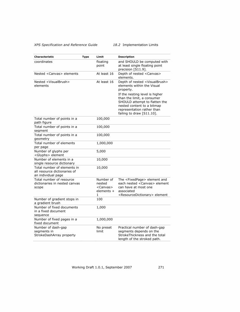
XPS Specification and Reference Guide 18.2 Implementation Limits
Working Draft 1.0.1, September 2007 271
Characteristic Type Limit Description
coordinates floating
point
and SHOULD be computed with
at least single floating point precision [S11.9].
Nested <Canvas> elements At least 16 Depth of nested <Canvas>
elements.
Nested <VisualBrush> elements
At least 16 Depth of nested <VisualBrush> elements within the Visual property.
If the nesting level is higher than the limit, a consumer
SHOULD attempt to flatten the nested content to a bitmap
representation rather than
failing to draw [S11.10].
Total number of points in a path figure
100,000
Total number of points in a
segment
100,000
Total number of points in a geometry
100,000
Total number of elements per page
1,000,000
Number of glyphs per
<Glyphs> element
5,000
Number of elements in a single resource dictionary
10,000
Total number of elements in all resource dictionaries of an individual page
10,000
Total number of resource dictionaries in nested canvas scope
Number of nested <Canvas> elements + 1
The <FixedPage> element and each nested <Canvas> element can have at most one associated <ResourceDictionary> element
Number of gradient stops in a gradient brush
100
Number of fixed documents in a fixed document sequence
1,000
Number of fixed pages in a fixed document
1,000,000
Number of dash-gap segments in StrokeDashArray property
No preset limit
Practical number of dash-gap segments depends on the StrokeThickness and the total length of the stroked path.

18.3 Gradient Computations Rendering Rules
272 Working Draft 1.0.1, September 2007
Characteristic Type Limit Description
Total size of XPS Document
markup per page
Bytes 64,000,000 Total size of markup after
removing all unnecessary whitespace (according to the
schema in B), assuming markup elements are specified in the default namespace without namespace prefixes, and assuming the most compact representation of all attributes using abbreviated syntax where possible.
18.3 Gradient Computations 1
To ensure the greatest possible consistency among consumers, gradients SHOULD be 2
rendered according to the guidelines described in this section [S11.11]. 3
18.3.1 All Gradients 4
Linear gradients and radial gradients share a common set of recommended 5
operations for pre-processing gradient stops and blending colors. These are 6
described below. 7
18.3.1.1 Gradient Stop Pre-Processing 8
Consumers SHOULD pre-process gradient stops for all gradients using the following 9
steps [S11.12]: 10
1. Sort all gradient stops by their respective offset values in ascending order. 11
When two or more gradient stops have the same offset value, preserve their 12
relative order from the markup while sorting. When more than two gradient 13
stops have the same offset value, remove all but the first and last gradient 14
stops having the same offset value. 15
2. If no gradient stop with an offset of 0.0 exists, 16
a. And no gradient stop with an offset less than 0.0 exists, create an artificial 17
gradient stop having an offset of 0.0 and a color of the gradient stop with 18
the smallest offset value. 19
b. And a gradient stop with an offset less than 0.0 exists and a gradient stop 20
with an offset greater than 0.0 exists, create an artificial gradient stop 21
having an offset of 0.0 and a color interpolated between the two gradient 22
stops surrounding 0.0. Discard all gradient stops with an offset less than 23
0.0. 24
c. And a gradient stop with an offset less than 0.0 exists and no gradient stop 25
with an offset greater than 0.0 exists, create an artificial gradient stop 26
having an offset of 0.0 and a color of the gradient stop with the largest 27
offset value. Discard all gradient stop elements with an offset less than 0.0. 28
. 29
3. If no gradient stop with an offset of 1.0 exists, 0. 30

XPS Specification and Reference Guide 18.3 Gradient Computations
Working Draft 1.0.1, September 2007 273
a. And no gradient stop with an offset of greater than 1.0 exists, create an 1
artificial gradient stop having an offset of 1.0 and a color equal to the color 2
of the gradient stop with the largest offset value. 3
b. And a gradient stop with an offset greater than 1.0 exists and a gradient 4
stop with an offset less than 1.0 exists, create an artificial gradient stop 5
having an offset of 1.0 and a color interpolated between the two 6
surrounding gradient stops. Discard all gradient stops with an offset greater 7
than 1.0. 8
c. And a gradient stop with an offset greater than 1.0 exists and no gradient 9
stop with an offset less than 1.0 exists, create an artificial gradient stop 10
having an offset of 1.0 and a color equal to that of the gradient stop with 11
the smallest offset value. Discard all gradient stops with an offset greater 12
than 1.0. . 13
18.3.1.2 Blending Colors 14
If any gradient stops use an sRGB or scRGB color specification or the consumer does 15
not understand the PageBlendColorSpace PrintTicket setting, consumers SHOULD 16
blend colors between gradient stops in the color space indicated by the 17
ColorInterpolationMode attribute of the gradient brush [S11.13]. If none of the 18
gradient stop elements uses an sRGB or scRGB color specification and the consumer 19
understands the PageBlendColorSpace PrintTicket setting, the PageBlendColorSpace 20
PrintTicket setting SHOULD be used [S11.13]. 21
The function used for blending is: 22
BLEND(offset, clo, chi) 23
Where the offset is between 0 and 1. clo and chi designate the color values for an 24
offset of 0 and 1, respectively. 25
If a ColorInterpolationMode value of SRgbLinearInterpolation is used, the 26
BLEND() function SHOULD convert the color values to sRGB first, and then perform a 27
linear interpolation between them [S11.14]. 28
If a ColorInterpolationMode value of ScRgbLinearInterpolation is used, the 29
BLEND() function SHOULD convert the color values to scRGB first, and then perform 30
a linear interpolation between them [S11.15]. 31
If blending is performed in the color space identified by the PageBlendColorSpace 32
PrintTicket setting, it SHOULD be a linear, channel-by-channel blend operation 33
[S11.13]. 34
In the presence of transformations or when individual gradient stops are very close 35
(separated by a few pixels or less in the device space), the local color gradient at the 36
offset used in the BLEND() function may be large, resulting in a large change over 37
the extent of a single device pixel. In this case, it is RECOMMENDED that the 38
BLEND() function interpolate the gradient over the extent of each device pixel 39
[S11.16]. However, the behavior MAY differ from this recommendation in an 40
implementation-specific manner [O11.7] and, therefore, producers SHOULD NOT rely 41
on a specific effect for such dense gradient specifications [S11.16]. 42
As a consequence of this interpolation, radial gradients that define the gradient 43
origin on or outside ellipse create an ―outside‖ area that can be rendered 44
inconsistently. The radial gradients that are affected are those that define multiple 45

18.3 Gradient Computations Rendering Rules
274 Working Draft 1.0.1, September 2007
gradient stops that are of different colors and are very close in Offset value to 0.0 or 1
1.0 (the gradient end points), for radial gradients with a SpreadMethod value of 2
Repeat or Reflect, respectively. For these affected gradients, consumers MAY use an 3
interpolated color value for the outside area [O11.8]. Depending on the resolution, 4
this can result in different colors than those defined by the gradient end points. The 5
closer a gradient stop is to the affected gradient end point, the more the rendering 6
results on different consumers and at different display resolutions can differ. 7
Producers SHOULD therefore either avoid such close gradient stops to the gradient 8
end point when specifying radial gradients where the outside area is visible or avoid 9
specifying radial gradients with a gradient origin on or outside the ellipse (in which 10
case there is no outside area) to ensure consistent rendering results [S11.17]. 11
18.3.2 Linear Gradients 12
Consumers SHOULD render an element filled with a linear gradient brush such that 13
the appearance is the same as if the following steps had been taken [S11.11]: 14
1. Transform the StartPoint and EndPoint attribute values using the current 15
effective render transform (including the render transform for the element 16
being filled by the linear gradient brush and the brush‘s transform itself). 17
2. If the SpreadMethod value is Pad, the colors of points on the line defined by 18
the StartPoint and EndPoint attributes are defined by interpolating the 19
coordinates linearly, and each color component (such as R, G, B for sRGB and 20
scRGB) as well as the alpha component is interpolated between the 21
component values of the closest enclosing gradient stops: 22
For each offset (real number) t < 0: 23
{ 24
x(t) = (EndPointx–StartPointx)*t+StartPointx 25
y(t) = (EndPointy-StartPointy)*t+StartPointy 26
c(t) = cfirst 27
a(t) = afirst 28
} 29
Where c is the color component and a is the alpha component. cfirst are the 30
color component values of the first gradient stop (after sorting) and afirst is 31
the alpha component value at the first gradient stop (after sorting). 32
For each offset (real number) 0 <= t <= 1: 33
{ 34
x(t) = (EndPointx-StartPointx)*t+StartPointx 35
y(t) = (EndPointy-StartPointy)*t+StartPointy 36
c(t) = BLEND((t-tlo)/(thi-tlo),clo,chi) 37
a(t) = [(t-tlo)/(thi-tlo)]*(ahi-alo)+alo 38
} 39
Where tlo and thi are the offsets, clo and chi are the color component values at 40
the closest enclosing gradient stops (that is, tlo <= t <= thi) and alo and ahi 41
are the alpha component values at the closest enclosing gradient stops (tlo <= 42
t <= thi). 43
For each offset (real number) t > 1: 44
{ 45
x(t) = (EndPointx-StartPointx)*t+StartPointx 46
y(t) = (EndPointy-StartPointy)*t+StartPointy 47
c(t) = clast 48
a(t) = alast 49
} 50
XPS Specification and Reference Guide 18.3 Gradient Computations
Working Draft 1.0.1, September 2007 275
Where clast are the color component values of the last gradient stop (after 1
sorting) and alast is the alpha component value at the last gradient stop (after 2
sorting). 3
3. If the SpreadMethod value is Repeat, the colors of points on the line defined 4
by the StartPoint and EndPoint attributes are defined by interpolating the 5
coordinates linearly, and each color component (such as R, G, B for sRGB and 6
scRGB) as well as the alpha component is interpolated between the 7
component values of the closest enclosing gradient stops: 8
For each repetition (all integers) N: 9
{ 10
For each offset (real number) 0 <= t < 1: 11
{ 12
x(t) = (EndPointx-StartPointx)*(N+t)+StartPointx 13
y(t) = (EndPointy-StartPointy)*(N+t)+StartPointy 14
c(t) = BLEND((t-tlo)/(thi-tlo),clo,chi) 15
a(t) = [(t-tlo)/(thi-tlo)]*(ahi-alo)+alo 16
} 17
} 18
Where c is the color component and a is the alpha component. tlo and thi are 19
the offsets, clo and chi are the color component values at the closest enclosing 20
gradient stops (that is, tlo <= t <= thi) and alo and ahi are the alpha 21
component values at the closest enclosing gradient stops (tlo <= t <= thi). 22
4. If the SpreadMethod value is Reflect, the colors of points on the line defined 23
by the StartPoint and EndPoint attributes are defined by interpolating the 24
coordinates linearly, and each color component (such as R, G, B for sRGB and 25
scRGB) as well as the alpha component is interpolated between the 26
component values of the closest enclosing gradient stops: 27
For each repetition (all integers) N: 28
{ 29
For each offset (real number) 0 <= t <= 1: 30
{ 31
If (N is EVEN) 32
{ 33
x(t) = (EndPointx-StartPointx)*(N+t)+StartPointx 34
y(t) = (EndPointy-StartPointy)*(N+t)+StartPointy 35
} 36
Else 37
{ 38
x(t) = (EndPointx-StartPointx)*(N+1-t)+StartPointx 39
y(t) = (EndPointy-StartPointy)*(N+1-t)+StartPointy 40
} 41
c(t) = BLEND((t-tlo)/(thi-tlo),clo,chi) 42
a(t) = [(t-tlo)/(thi-tlo)]*(ahi-alo)+alo 43
} 44
} 45
Where c is the color component and a is the alpha component. tlo and thi are 46
the offsets, clo and chi are the color component values at the closest enclosing 47
gradient stops (that is, tlo <= t <= thi) and alo and ahi are the alpha 48
component values at the closest enclosing gradient stops (tlo <= t <= thi). 49
5. The colors of points not on the extended line defined by the StartPoint and 50
EndPoint attributes are the same as the color of the closest point on the line 51
defined by the StartPoint and EndPoint attributes, measured in the 52
coordinate space as transformed by the current effective render transform 53

18.3 Gradient Computations Rendering Rules
276 Working Draft 1.0.1, September 2007
(including the render transform for the element being filled by the linear 1
gradient brush and the brush‘s transform itself). 2
6. Clip the resulting set of points to the intersection of the current clip geometry 3
and the path or glyphs to be filled. Both the clip and path (or glyphs) must be 4
transformed according to the current effective render transform, including the 5
render transform for the element being filled, but not including the transform 6
of the linear gradient brush.0. 7
For purposes of the above steps, the closest enclosing gradient stops mean the 8
gradient stops that, if the relative sequencing of the gradient stop offsets in the 9
markup order is respected, are numerically closest to the interpolation point if that 10
interpolation point were converted to an offset value and inserted in a sorted fashion 11
into the list of gradient stops. [Example: If a gradient contains three gradient stops 12
at offset values 0.0, 0.0, and 1.0, the closest enclosing gradient stops for any value 13
0 <= value <= 1 are the second gradient stop (offset 0.0) and the third gradient 14
stop (offset 1.0). end example] 15
18.3.3 Radial Gradients 16
Consumers SHOULD render an element filled with a radial gradient brush such that 17
the appearance is the same as if these steps had been followed [S11.11]: 18
1. The boundary of the area filled by a radial gradient brush is defined by 19
interpolating ellipses from the GradientOrigin value to the circumference of 20
the ellipse centered at the point specified by the Center attribute with radii 21
equal to the RadiusX and RadiusY attribute values(the interpolated ellipses 22
and point being transformed by the current effective render transform, 23
including the render transform for the element being filled by the radial 24
gradient brush and the brush‘s transform itself). If the gradient origin is 25
outside the circumference of the ellipse specified, the effect will be as if a cone 26
were drawn, tapering to the gradient origin. 27
2. If the SpreadMethod value is Pad, the centers and radii of the interpolated 28
ellipses are defined by linearly interpolating the center of the ellipse from the 29
GradientOrigin attribute value to the Center attribute value, and 30
simultaneously linearly interpolating the radii of the ellipse from 0 to the 31
RadiusX and RadiusY attribute values: 32
For each offset (real number) 0 <= t <= 1: 33
{ 34
cx(t) = (Centerx-GradientOriginx)*t+GradientOriginx 35
cy(t) = (Centery-GradientOriginy)*t+GradientOriginy 36
rx(t) = RadiusX*t 37
ry(t) = RadiusY*t 38
} 39
The ellipses defined by the interpolation are transformed by the current 40
effective render transform, including the render transform for the element 41
being filled by the radial gradient brush and the brush‘s transform itself. 42
3. The colors of the points within the boundary of this shape are defined as the 43
color of the smallest interpolated ellipse containing the point. The color of an 44
interpolated ellipse is defined by interpolating each color component (such as 45
R, G, B for sRGB and scRGB) as well as the alpha component between the 46
component values of the closest enclosing gradient stops: 47

XPS Specification and Reference Guide 18.3 Gradient Computations
Working Draft 1.0.1, September 2007 277
For each offset (real number) 0 <= t <= 1: 1
{ 2
c(t) = BLEND((t-tlo)/(thi-tlo),clo,chi) 3
a(t) = [(t-tlo)/(thi-tlo)]*(ahi-alo)+alo 4
} 5
Where tlo and thi are the offsets, clo and chi are the color component values at 6
the closest enclosing gradient stops (that is, tlo <= t <= thi) and alo and ahi 7
are the alpha component values at the closest enclosing gradient stops (tlo <= 8
t <= thi). 9
4. If the SpreadMethod value is Repeat, the centers and radii of the 10
interpolated ellipses are defined by linearly interpolating the center of the 11
ellipse from the GradientOrigin attribute value to the Center attribute value, 12
and simultaneously linearly interpolating the radii of the ellipse from 0 to 13
RadiusX and RadiusY attribute values: 14
For each repetition (all non-negative integers) N: 15
{ 16
For each offset (real number) 0 <= t < 1: 17
{ 18
cx(t) = (Centerx-GradientOriginx)*(N+t)+GradientOriginx 19
cy(t) = (Centery-GradientOriginy)*(N+t)+GradientOriginy 20
rx(t) = RadiusX*(N + t) 21
ry(t) = RadiusY*(N + t) 22
} 23
} 24
The ellipses defined by the interpolation are transformed by the current 25
effective render transform, including the render transform for the element 26
being filled by the radial gradient brush and the brush‘s transform itself. 27
5. The colors of the points within the boundary of this shape are defined as the 28
color of the smallest interpolated ellipse containing the point. The color of an 29
interpolated ellipse is defined by interpolating each color component (such as 30
R, G, B for sRGB and scRGB) as well as the alpha component between the 31
component values of the closest enclosing gradient stops: 32
For each repetition (all non-negative integers) N: 33
{ 34
For each offset (real number) 0 <= t < 1: 35
{ 36
c(t) = BLEND((t-tlo)/(thi-tlo),clo,chi) 37
a(t) = [(t-tlo)/(thi-tlo)]*(ahi-alo)+alo 38
} 39
} 40
Where tlo and thi are the offsets, clo and chi are the color component values at 41
the closest enclosing gradient stops (that is, tlo <= t <= thi) and alo and ahi 42
are the alpha component values at the closest enclosing gradient stops (tlo <= 43
t <= thi). 44
6. If the SpreadMethod value is Reflect, the centers and radii of the 45
interpolated ellipses are defined by linearly interpolating the center of the 46
ellipse from the GradientOrigin attribute value to the Center attribute value, 47
and simultaneously linearly interpolating the radii of the ellipse from 0 to the 48
RadiusX and RadiusY attribute values: . 49
For each non-negative integer N: 50
{ 51
For each offset (real number) 0 <= t <= 1: 52

18.3 Gradient Computations Rendering Rules
278 Working Draft 1.0.1, September 2007
{ 1
cx(t) = (Centerx-GradientOriginx)*(N+t)+GradientOriginx 2
cy(t) = (Centery-GradientOriginy)*(N+t)+GradientOriginy 3
rx(t) = RadiusX*(N+t) 4
ry(t) = RadiusY*(N+t) 5
} 6
} 7
The ellipses defined by the interpolation are transformed by the current 8
effective render transform, including the render transform for the element 9
being filled by the radial gradient brush and the brush‘s transform itself. 10
7. The colors of the points within the boundary of this shape are defined as the 11
color of the smallest interpolated ellipse containing the point. The color of an 12
interpolated ellipse is defined by interpolating each color component (such as 13
R, G, B for sRGB and scRGB) as well as the alpha component between the 14
component values of the closest enclosing gradient stops: 15
For each non-negative integer N: 16
{ 17
For each offset (real number) 0 <= t <= 1: 18
{ 19
If N is ODD 20
t' = 1–t 21
Else 22
t' = t 23
24
c(t) = BLEND((t'-tlo)/(thi-tlo),clo,chi) 25
a(t) = [(t'-tlo)/(thi-tlo)]*(ahi-alo)+alo 26
} 27
} 28
Where tlo and thi are the offsets, clo and chi are the color component values at 29
the closest enclosing gradient stops (that is, tlo <= t <= thi) and alo and ahi 30
are the alpha component values at the closest enclosing gradient stops (tlo <= 31
t <= thi). 32
8. The colors of points outside the boundary of this shape (points which cannot 33
be drawn by any combination of non-negative N and t) are defined as having 34
the color and alpha defined in the gradient stop with the offset of 0.0 for radial 35
gradients with a SpreadMethod value of Reflect and the color and alpha 36
defined in the gradient stop with the offset of 1.0 for radial gradients with a 37
SpreadMethod value of Repeat or Pad. The colors outside of the boundary of 38
this shape may also vary in an implementation-specific manner 39
(see §18.3.1.2, ―Blending Colors‖ for more details). 40
9. Clip the resulting set of points by the intersection of the current clip geometry 41
and the path or glyphs to be filled. Both the clip and path (or glyphs) must be 42
transformed according to the current effective render transform, including the 43
render transform for the element being filled, but not including the transform 44
of the radial gradient brush. 0. 45
For purposes of the above steps, the closest enclosing gradient stops mean the 46
gradient stops that, if the relative sequencing of the gradient stop offsets in the 47
markup order is respected, are numerically closest to the interpolation point if that 48
interpolation point were converted to an offset value and inserted in a sorted fashion 49
into the list of gradient stops. [Example: If a gradient contains three gradient stops 50
at offset values 0.0, 0.0, and 1.0, the closest enclosing gradient stops for any value 51

XPS Specification and Reference Guide 18.4 Opacity Computations
Working Draft 1.0.1, September 2007 279
0 <= value <= 1 are the second gradient stop (offset 0.0) and the third gradient 1
stop (offset 1.0). end example] 2
18.4 Opacity Computations 3
Opacity is used to transparently blend two elements when rendering, also known as 4
alpha blending. The value of the Opacity property ranges from 0.0 (fully transparent) 5
to 1.0 (fully opaque), inclusive. Values outside of this range are invalid. 6
The opacity is applied through the following computations, assuming source and 7
destination values are not pre-multiplied. All opacity calculations SHOULD be 8
performed with at least 8-bit precision to provide sufficient quality for nested content 9
[S11.18]. 10
Individual pixels are blended as defined below. 11
Table 18–2. Opacity computation symbols 12
Symbol Description
OE Opacity attribute of element
OM Alpha value at corresponding pixel position in the OpacityMask attribute value
AS Alpha value present in source color
RS Red value present in source color
GS Green value present in source color
BS Blue value present in source color
AD Alpha value already present in destination surface
RD Red value already present in destination surface
GD Green value already present in destination surface
BD Blue value already present in destination surface
A* Resulting Alpha value for destination surface
R* Resulting Red value for destination surface
G* Resulting Green value for destination surface
B* Resulting Blue value for destination surface
All values designated with a T subscript (as in RT1) are temporary values. 13
The opacity is calculated as follows: 14
1. Multiply source alpha value with opacity value and alpha value of opacity 15
mask. 16
AS1 = AS*OE*OM 17
2. Pre-multiply source alpha. 18
Omit this step if the source data specifies pre-multiplied alpha (see §18.4.1, 19
―Pre-Multiplied Alpha and Superluminous Colors,‖ on page 281 for details). 20
AT1 = AS1 21
RT1 = RS*AS1 22
GT1 = GS*AS1 23

18.4 Opacity Computations Rendering Rules
280 Working Draft 1.0.1, September 2007
BT1 = BS*AS1 1
3. Pre-multiply destination alpha. 2
Omit this step in consumers supporting superluminous colors (see §18.4.1, 3
―Pre-Multiplied Alpha and Superluminous Colors,‖ on page 281 for details). 4
AT2 = AD 5
RT2 = RD*AD 6
GT2 = GD*AD 7
BT2 = BD*AD 8
4. Blend. 9
See §18.4.1, ―Pre-Multiplied Alpha and Superluminous Colors,‖ on page 281 10
for special case handling. 11
AT3 = (1-AT1)*AT2+AT1 12
RT3 = (1-AT1)*RT2+RT1 13
GT3 = (1-AT1)*GT2+GT1 14
BT3 = (1-AT1)*BT2+BT1 15
5. Reverse pre-multiplication. 16
Omit this step in consumers supporting superluminous colors. See 17
also §18.4.1, ―Pre-Multiplied Alpha and Superluminous Colors,‖ on page 281. 18
The resulting color channel values are divided by the resulting alpha value. If 19
the resulting alpha value is 0, all color channels are set to 0 by definition, as 20
expressed in the If condition below. Each of RT3, GT3, BT3 is smaller than or 21
equal to AT3 and, therefore, each of the resulting R*, G*, B* is in the valid 22
interval of [0.0,1.0] after the pre-multiplication is reversed.0. 23
If AT3 = 0 24
{ 25
set all A* R* G* B* to 0. 26
} 27
Else 28
{ 29
A* = AT3 30
R* = RT3/AT3 31
G* = GT3/AT3 32
B* = BT3/AT3 33
} 34
When blending colors in a color space other than sRGB, color channels are 35
independently interpolated in a manner analogous to the RGB channel blending 36
method described above. 37

XPS Specification and Reference Guide 18.4 Opacity Computations
Working Draft 1.0.1, September 2007 281
18.4.1 Pre-Multiplied Alpha and Superluminous Colors 1
The alpha information in TIFF images using an ExtraSamples tag value of 1 and in 2
Windows Media Photo images using pixel formats WICPixelFormat32bppPBGRA, 3
WICPixelFormat64bppPRGBA or WICPixelFormat128bppPRGBAFloat MUST be 4
interpreted as pre-multiplied alpha information [M11.6]. In certain scenarios (such 5
as when rendering 3D scenes to a bitmap), producers MAY choose to create pre-6
multiplied bitmap data specifying ―superluminous‖ colors [O11.9]. 7
Superluminous colors are defined as pre-multiplied color values with an alpha value 8
smaller than the individual color channel values but greater than or equal to 0. 9
The effect of composing superluminous colors on a background is similar to adding 10
additional light of the source color to the destination, as opposed to regular alpha 11
composition which works more like a colored filter. One can easily verify this 12
statement by substituting 0 for AT1 in step 4 of the above opacity computations, 13
which is simplified as follows (note that RT1 , GT1 , BT1 are not 0, because the pre-14
multiplication in step 2 has been skipped): 15
AT3 = AT2 16
RT3 = RT2+RT1 17
GT3 = GT2+GT1 18
BT3 = BT2+BT1 19
Consumers supporting superluminous colors retain all temporary information in pre-20
mulitplied formats. Note, that throughout the XPS specification non-pre-multiplied 21
alpha processing is assumed. It is up to the implementer of such a consumer to 22
identify equivalent composition and rendering rules for processing in pre-multiplied 23
space. 24
Also note, when composing superluminous colors, management of out-of-gamut 25
colors SHOULD be deferred until the result is rendered to the final target, at which 26
point out-of-gamut colors are clipped or color managed [S11.19]. 27
Consumers MAY handle superluminous colors or MAY instead choose to convert pre-28
multiplied source data containing superluminous colors to non-pre-multiplied data 29
before composition by ignoring the superluminous portion of each color channel 30
value [O11.10], as described in the following steps: 31
For each superluminous pixel with A < R or A < G or A < B 32
{ 33
If A = 0 34
{ 35
R* = 1 36
G* = 1 37
B* = 1 38
} 39
Else 40
{ 41
A* = A 42
R* = min(R/A,1) 43
G* = min(G/A,1) 44
B* = min(B/A,1) 45
} 46
} 47

18.5 Composition Rules Rendering Rules
282 Working Draft 1.0.1, September 2007
18.5 Composition Rules 1
XPS Document page markup uses the painter‘s model with alpha channel. 2
Composition MUST have the same effect as the application of the following rules, in 3
sequence [M11.7]: 4
1. In order to render a fixed page or canvas, a surface is created to hold the 5
drawing content as it is composed. The color and appearance of this surface 6
SHOULD match the destination color and appearance, typically a solid white 7
background for a fixed page or transparent for a canvas [S11.20]. An 8
implementation MAY choose to meet this goal by always initializing this 9
surface‘s alpha channel to 0.0 (transparent) and the color value to black 10
[O11.5]. 11
2. The fixed page or canvas represents a surface onto which child elements are 12
drawn. The child elements are drawn in the order they appear in markup. In 13
practice, an implementation might represent the surface by a bitmap buffer 14
large enough to hold all the drawing content produced when the child 15
elements are rendered. 16
3. The contents appearing on the surface of canvas are transformed using the 17
affine transform specified by the RenderTransform property of the canvas. (A 18
fixed page does not have a RenderTransform property.) 19
4. All child elements are rendered to the surface and clipped to the imageable 20
area of the physical display (such as a sheet of paper) of the fixed page or 21
according to the Clip property of a canvas. The geometry value of the canvas‘ 22
Clip property is also transformed using the affine transform specified by the 23
RenderTransform property of the canvas. 24
5. If a path has a Stroke and a Fill property, and also specifies Opacity or 25
OpacityMask property values, additional composition steps must be followed: 26
a. Create a temporary canvas with the opacity, opacity mask, clip, and render 27
transform specified by the path. 28
b. Create a copy of the original path, remove all but the Fill property from the 29
copy, and add the copy to the temporary canvas. 30
c. Create another copy of the original path, remove all but the stroke-related 31
properties (such as Stroke, StrokeThickness, and StrokeDashArray) from 32
the copy, and add the copy to the temporary canvas. 33
d. Do not draw the original path. 34
e. Draw the temporary canvas, while recursively applying the composition 35
rules. . 36
6. If a grouping element (a <Canvas> element) has an Opacity or OpacityMask 37
property, additional composition steps must be followed: 38
a. Create a temporary surface and set its alpha channel to 0.0 (transparent) 39
and its color value to black. 40
b. Compose all child elements of the grouping element onto the temporary 41
surface, while recursively applying the composition rules. 42
c. Cumulatively apply the opacity of the grouping element and opacity mask 43
to the alpha channel of the temporary surface. 44

XPS Specification and Reference Guide 18.5 Composition Rules
Working Draft 1.0.1, September 2007 283
d. Draw the contents of the temporary surface onto the containing surface. . 1
7. If a non-grouping element (a <Path> or <Glyphs> element) has an Opacity 2
property, an OpacityMask property, or a fill or stroke using transparency, the 3
following additional composition steps must be taken: 4
a. If the element has a RenderTransform property, apply it to the element and 5
its Clip, Fill, Stroke, and OpacityMask properties, if present. 6
b. Create a mask from the set of all painted pixels representing the child 7
element (after the Clip property of the element has been applied). . 8
8. Combine the Fill or Stroke property with the OpacityMask and the Opacity 9
property and apply to the surface through the computed mask. For more 10
information, see §14.1, ―Opacity,‖ on page 172.0. 11
The behavior that results from this process is: 12
Opacity is not applied cumulatively to self-overlapping areas created when 13
rendering an individual <Glyphs> element. 14
Opacity is not applied cumulatively to self-overlapping areas created by 15
<PathFigure> elements within the same path (see Example 18–1 on 16
page 284). 17
Opacity is not applied cumulatively if the border of a path has self-18
intersections. When the border of a path is stroked, the area of the path is 19
filled by first applying the brush specified by the Fill property. After filling the 20
area, the border is drawn using the stroke-related properties including the 21
brush specified by the Stroke property, with half the stroke width extending 22
outside the filled area and half extending inside (see Example 18–2 on 23
page 285). If the path has self-intersections, the opacity is not accumulated. 24
The color of the stroke and the color of the filled area are combined on the 25
inside half of a stroked border (overlapping the filled area of the path) if the 26
brush specified by the Stroke property is transparent. 27
If a path that has a stroked border has an opacity of less than 1.0 or an 28
opacity mask, the path (filled area and stroked border) is first rendered onto a 29
temporary surface using an opacity of 1.0 and no opacity mask (while 30
preserving any transparency of the fill or the stroked border themselves), and 31
the resulting figure is drawn onto the background using the specified opacity 32
and opacity mask (see Example 18–3 on page 285). 33
18.5.1 Optimization Guidelines 34
The composition rules above describe the behavior of an ideal implementation. 35
Practical implementations can optimize the processing of the composition rules 36
according to the following guidelines: 37
1. If all elements on a canvas and the canvas itself are opaque (an opacity of 38
1.0) and parent or ancestor <Canvas> elements are also opaque, the 39
elements MAY be drawn directly to the containing fixed page (or canvas), 40
provided all render transform and clip values are observed [O11.12]. 41
2. If an element is fully transparent (an opacity of 0.0), it MAY be skipped 42
[O11.13]. 43

18.5 Composition Rules Rendering Rules
284 Working Draft 1.0.1, September 2007
3. If a canvas has an opacity of 0.0, it and all of its child and descendant 1
elements MAY be skipped [O11.14]. 2
4. If a canvas has a Clip property with no contained area, the canvas and all of 3
its child and descendant elements MAY be skipped [O11.15]. 4
5. When creating a temporary surface, a consumer MAY further restrict the size 5
of the temporary surface by the effective extent of the geometry specified by 6
the Clip property of the canvas [O11.16]. 7
6. A consumer MAY use methods to achieve transparency other than creating a 8
temporary surface [O11.17]. Such methods MAY include planar mapping (that 9
is, computation of intersections of transparent elements and resulting colors) 10
[O11.17].0. 11
18.5.2 Composition Examples 12
The following examples illustrate the composition rules described above. 13
Example 18–1. Path opacity behavior for overlapping path figures 14
In the following markup, opacity is not applied cumulatively to self-overlapping areas 15
created by path figures within the same path. 16
<Path Opacity="0.5"> 17
<Path.Fill> 18
<SolidColorBrush Color="#0000FF" /> 19
</Path.Fill> 20
<Path.Data> 21
<PathGeometry FillRule="NonZero"> 22
<PathFigure StartPoint="10,10" IsClosed="true"> 23
<PolyLineSegment Points="110,10 110,110 10,110 10,10" /> 24
</PathFigure> 25
<PathFigure StartPoint="50,50" IsClosed="true"> 26
<PolyLineSegment Points="150,50 150,150 50,150 50,50" /> 27
</PathFigure> 28
</PathGeometry> 29
</Path.Data> 30
</Path> 31
This markup is rendered as follows: 32
33
end example] 34

XPS Specification and Reference Guide 18.5 Composition Rules
Working Draft 1.0.1, September 2007 285
Example 18–2. Opacity behavior of path stroke intersections 1
In the following markup, opacity is not applied cumulatively if the border of a path 2
has self-intersections. 3
<Path Stroke="#80FF0000" StrokeThickness="10"> 4
<Path.Fill> 5
<SolidColorBrush Color="#0000FF" /> 6
</Path.Fill> 7
<Path.Data> 8
<PathGeometry FillRule="NonZero"> 9
<PathFigure StartPoint="20,20" IsClosed="true"> 10
<PolyLineSegment Points="120,20 120,120 20,120 20,20" /> 11
</PathFigure> 12
<PathFigure StartPoint="50,50" IsClosed="true"> 13
<PolyLineSegment Points="150,50 150,150 50,150 50,50" /> 14
</PathFigure> 15
</PathGeometry> 16
</Path.Data> 17
</Path> 18
<Path Stroke="#80FF0000" StrokeThickness="10" StrokeMiterLimit="10"> 19
<Path.Fill> 20
<SolidColorBrush Color="#0000FF" /> 21
</Path.Fill> 22
<Path.Data> 23
<PathGeometry> 24
<PathFigure StartPoint="220,20" IsClosed="true"> 25
<PolyLineSegment Points="420,220 420,20 220,120" /> 26
</PathFigure> 27
</PathGeometry> 28
</Path.Data> 29
</Path> 30
This markup is rendered as follows: 31
32
end example] 33
Example 18–3. Opacity behavior of paths with stroked edges 34
The following markup describes a path with a stroked border and an opacity of less 35
than 1.0: 36
<Path> 37
<Path.Fill> 38

18.5 Composition Rules Rendering Rules
286 Working Draft 1.0.1, September 2007
<SolidColorBrush Color="#7F7F7F" /> 1
</Path.Fill> 2
<Path.Data> 3
<PathGeometry> 4
<PathFigure StartPoint="0,110" IsClosed="true"> 5
<PolyLineSegment Points="450,110 450,210 0,210" /> 6
</PathFigure> 7
</PathGeometry> 8
</Path.Data> 9
</Path> 10
<Path 11
Stroke="#FF0000" 12
StrokeThickness="10" 13
StrokeDashArray="2.2 3.5" 14
StrokeDashCap="Round" 15
Opacity="0.5"> 16
<Path.Fill> 17
<SolidColorBrush Color="#0000FF" /> 18
</Path.Fill> 19
<Path.Data> 20
<PathGeometry FillRule="NonZero"> 21
<PathFigure StartPoint="10,10" IsClosed="true"> 22
<PolyLineSegment Points="110,10 110,110 10,110 10,10" /> 23
</PathFigure> 24
<PathFigure StartPoint="60,60" IsClosed="true"> 25
<PolyLineSegment Points="160,60 160,160 60,160 60,60" /> 26
</PathFigure> 27
</PathGeometry> 28
</Path.Data> 29
</Path> 30
<Path Stroke="#FF0000" StrokeThickness="10" Opacity="0.5"> 31
<Path.Fill> 32
<SolidColorBrush Color="#0000FF" /> 33
</Path.Fill> 34
<Path.Data> 35
<PathGeometry> 36
<PathFigure StartPoint="200,60" IsClosed="true"> 37
<PolyLineSegment Points="400,160 400,60 200,160" /> 38
</PathFigure> 39
</PathGeometry> 40
</Path.Data> 41
</Path> 42
This markup is rendered as follows: 43
44

XPS Specification and Reference Guide 18.5 Composition Rules
Working Draft 1.0.1, September 2007 287
end example] 1

18.6 Stroke Rendering Rendering Rules
288 Working Draft 1.0.1, September 2007
18.6 Stroke Rendering 1
Strokes follow the contours of each segment in a path figure, as specified by the 2
various stroke-related properties. 3
Contours and dashes SHOULD be rendered so that they have the same appearance 4
as if rendered by sweeping the complete length of the contour or dash with a line 5
segment that is perpendicular to the contour and extends with half its length to each 6
side of the contour. All points covered by the sweep of this perpendicular line are 7
part of the dash or contour [S11.21]. 8
By using this sweeping definition, extreme curvatures may result in line and dash 9
ends that are not flat when specified as flat. If any caps other than flat are specified, 10
the caps are added to the start and end of the stroked contour or dash in the 11
orientation of the first and last position of the line segment used for sweeping. Any 12
render transform is applied after this step. 13
[Note: Using this definition, any geometry that is less than the value of the stroke 14
thickness across will produce a filled area between these lines if no dashes are 15
employed, or overlapping dashes when they are. end note] 16
Figure 18–2. Extreme curvatures and dash rendering 17
18
18.6.1 Stroke Edge Parallelization 19
Consumers SHOULD ensure that parallel edges of strokes appear parallel [S11.22]. 20
Consumers can choose a suitable method to achieve this goal. [Example: Such 21
methods might include anti-aliasing, sub-pixel masking, or appropriate rounding of 22
device coordinates. end example] 23
18.6.2 Phase Control 24
Consumers SHOULD produce a visually consistent appearance of stroke thickness for 25
thin lines, regardless of their orientation or how they fit on the device pixel grid 26
[S11.23]. 27
18.6.3 Symmetry of Stroke Drawing Algorithms 28
Consumers SHOULD select line and curve drawing algorithms that behave 29
symmetrically and result in the same set of device pixels being drawn regardless of 30
the direction of the line or curve (start point and end point exchanged) [S11.24]. In 31

XPS Specification and Reference Guide 18.6 Stroke Rendering
Working Draft 1.0.1, September 2007 289
other words, a line from 0,0 to 102,50 should result in the same pixel set as a line 1
from 102,50 to 0,0. 2
18.6.4 Rules for Dash Cap Rendering 3
The appearance of dash caps is controlled by the StrokeDashCap attribute. Valid 4
values are Flat, Square, Round, and Triangle. 5
18.6.4.1 Flat Dash Caps 6
The effective render transform of the path being stroked is used to transform the 7
control points of the contour of the dash. 8
The length of the dash is the approximate distance on the curve between the two 9
intersections of the flat lines ending the dash and the contour of the shape. The 10
distance from the end of one dash to the start of the next dash is the specified dash 11
gap length. Dashes with a length greater than 0 are drawn, and degenerate dashes 12
with a length of 0 are not drawn. 13
Figure 18–3. Flat dash caps 14
15
18.6.4.2 Square Dash Caps 16
The effective render transform of the path being stroked is used to transform the 17
control points of the contour of the dash. 18
The length of the dash is the approximate distance on the curve between the two 19
contour intersection points, that is, the intersection of the flat line ending the dash 20
(without the square caps attached) and the contour of the shape. 21
The caps are drawn as half-squares attached to the ends of the dash. The boundaries 22
of the square caps are not curved to follow the contour, but are transformed using 23
the effective render transform. 24
The distance between the contour intersection points of consecutive dashes is the 25
specified dash gap length. Degenerate dashes with a length of 0 are drawn as 26
squares. 27

18.6 Stroke Rendering Rendering Rules
290 Working Draft 1.0.1, September 2007
Figure 18–4. Square dash caps 1
2
18.6.4.3 Round Dash Caps 3
The effective render transform of the path being stroked is used to transform the 4
control points of the contour of the dash. 5
The length of the dash is the approximate distance on the curve between the two 6
contour intersection points, that is, the intersection of the flat line ending the dash 7
(without the round caps attached) and the contour of the shape. 8
The caps are drawn as half-circles attached to the ends of the dash. The boundaries 9
of the round caps are not distorted to follow the contour, but are transformed using 10
the effective render transform. 11
The distance between the contour intersection points of consecutive dashes is the 12
specified dash gap length. Degenerate dashes with a length of 0 are drawn as circles. 13
Figure 18–5. Round dash caps 14
15
18.6.4.4 Triangular Dash Caps 16
The effective render transform of the path being stroked is used to transform the 17
control points of the contour of the dash. 18
The length of the dash is the approximate distance on the curve between the two 19
contour intersection points, that is, the intersection of the flat line ending the dash 20
(without the triangular caps attached) and the contour of the shape. 21
The caps are drawn as triangles attached with their base to the ends of the dash. 22
The boundaries of the triangular caps are not distorted to follow the contour, but are 23
transformed using the effective render transform. The height of the triangles is half 24
of the stroke width. 25

XPS Specification and Reference Guide 18.6 Stroke Rendering
Working Draft 1.0.1, September 2007 291
The distance between the contour intersection points of consecutive dashes is the 1
specified dash gap length. Degenerate dashes with a length of 0 are drawn as 2
diamonds. 3
Figure 18–6. Triangular dash caps 4
5
18.6.4.5 Overlapping Dashes 6
It is possible to specify dash sequences with overlapping dash caps. In this 7
circumstance, the union of the dash segments (inclusive of dash caps), is used as a 8
mask through which the brush is applied as illustrated in Figure 18–7 with a stroke 9
dash cap value of Round. 10
Figure 18–7. Overlapping dash segments 11
12
18.6.5 Rules for Line Cap Rendering 13
The appearance of line caps is controlled by the StrokeStartLineCap and 14
StrokeEndLineCap attribute. Valid values are Flat, Square, Triangle, and Round. 15
Every start line cap can be used in combination with any end line cap. Line caps are 16
not drawn for closed paths. 17
The rules for line caps on curved lines are analogous to the rules for dash cap 18
rendering. For more information, see §18.6, ―Stroke Rendering,‖ on page 288 19
and §18.6.4, ―Rules for Dash Cap Rendering,‖ on page 289. 20

18.6 Stroke Rendering Rendering Rules
292 Working Draft 1.0.1, September 2007
Figure 18–8. Flat start line cap, flat end line cap 1
2
Figure 18–9. Square start line cap, square end line cap 3
4
Figure 18–10. Triangular start line cap, triangular end line cap 5
6
Figure 18–11. Round start line cap, round end line cap 7
8
18.6.6 Line Caps for Dashed Strokes 9
If the start point of a stroke is within a dash or touches the start or end of a dash, a 10
start line cap is appended to the stroke. Similarly, if the end point of a stroke is 11
within a dash or touches the start or end of a dash, an end line cap is appended to 12
the stroke. 13
Figure 18–12. Stroke start or end point within a dash 14
15
[Note: Because the right-most line cap begins at the point exactly coincident with 16
the start of the next dash in the sequence, it is rendered. end note] 17
However, if the start point of a stroke is within a gap (as can result from a 18
StrokeDashOffset attribute), no start line cap is appended to the stroke. If the end 19
point of a stroke is within a gap, no end line cap is appended to the stroke. 20
Figure 18–13. Stroke start or end point within a gap 21
22

XPS Specification and Reference Guide 18.6 Stroke Rendering
Working Draft 1.0.1, September 2007 293
18.6.7 Rules for Line Join Rendering 1
The appearance of line joins is controlled by the StrokeLineJoin attribute. Valid 2
values are Round, Bevel, and Miter. 3
18.6.7.1 Round Line Joins 4
A StrokeLineJoin attribute value of Round indicates that the outer corner of the 5
joined lines should be filled by enclosing the rounded region with its center point at 6
the point of intersection between the two lines and a radius of one-half the stroke 7
thickness value. 8
Figure 18–14. Round line join with right angle 9
10
Figure 18–15. Round line join with acute angle 11
12

18.6 Stroke Rendering Rendering Rules
294 Working Draft 1.0.1, September 2007
Figure 18–16. Round line join with obtuse angle 1
2
18.6.7.2 Beveled Line Joins 3
A StrokeLineJoin attribute value of Bevel indicates that the outer corner of the 4
joined lines should be filled by enclosing the triangular region of the corner with a 5
straight line between the outer corners of each stroke. 6
Figure 18–17. Beveled line join with right angle 7
8
Figure 18–18. Beveled line join with acute angle 9
10

XPS Specification and Reference Guide 18.6 Stroke Rendering
Working Draft 1.0.1, September 2007 295
Figure 18–19. Beveled line join with obtuse angle 1
2
18.6.7.3 Mitered Line Joins 3
If the StrokeLineJoin attribute value is Miter, the value of the StrokeMiterLimit 4
attribute value is also used for rendering these joins. A StrokeLineJoin value of 5
Miter indicates that the region to be filled includes the intersection of the strokes 6
projected to infinity, and then clipped at a specific distance. The intersection of the 7
strokes is clipped at a line perpendicular to the bisector of the angle between the 8
strokes, at the distance equal to the stroke miter limit value multiplied by half the 9
stroke thickness value. 10
When drawing mitered line joins, the presence of one or more degenerate line 11
segments between the non-degenerate line segments to be joined results in a 12
mitered line join of only the two non-degenerate line segments with an implied 13
StrokeMiterLimit attribute value of 1.0. 14
Figure 18–20. Mitered line join with right angle and miter limit of 1.0 15
16

18.6 Stroke Rendering Rendering Rules
296 Working Draft 1.0.1, September 2007
Figure 18–21. Mitered line join with acute angle and miter limit of 1.0 1
2
Figure 18–22. Mitered line join with obtuse angle and miter limit of 1.0 3
4
Figure 18–23. Mitered line join with right angle and miter limit of 2.0 5
6

XPS Specification and Reference Guide 18.6 Stroke Rendering
Working Draft 1.0.1, September 2007 297
Figure 18–24. Mitered line join with acute angle and miter limit of 2.0 1
2
Figure 18–25. Mitered line join with acute angle and miter limit of 10.0 3
4
18.6.8 Rules for Degenerate Line and Curve Segments 5
Degenerate line segments (that is, where the start point and end point coincide) are 6
not drawn. 7
Degenerate curve segments (where the start point, end point, and all control points 8
coincide) are not drawn, regardless of the stroke start line cap or stroke end line cap 9
specified. 10
If an open degenerate path (formed from degenerate line or curve segments) with 11
non-flat start cap and/or non-flat end line cap is stroked, only the start line cap 12
and/or end line cap is drawn, in the x direction relative to the current effective 13
render transform (that is, as if a segment were drawn from x,y to x+d,y, with d 14
0). 15
If a closed degenerate path (formed from degenerate line or curve segments) is 16
stroked, a circular dot with a diameter of the stroke thickness is drawn instead. 17

18.6 Stroke Rendering Rendering Rules
298 Working Draft 1.0.1, September 2007
If the current render transform is an invertible matrix, consumers SHOULD perform 1
computations on poly line segments and poly Bézier segments with sufficient 2
accuracy to avoid producing zero-length segments [S11.25]. 3
18.6.9 Stroking and Fill Rule 4
Stroking a path is independent of the fill rule. The fill rule affects the filled area only. 5
18.6.10 Mixing Stroked and Non-Stroked Segments 6
When a path figure contains multiple segments and one or more of the segments has 7
an IsStroked value of false, the phase for dashes starts anew with the next stroked 8
segment, including application of the dash offset. 9
When a segment is stroked and the subsequent segment has an IsStroked value of 10
false, thus causing a dash to be truncated, the dash cap is drawn for both ends of 11
the truncated dash, exactly as it would for a non-truncated dash. 12
18.6.11 Stroke Behavior with Multiple Path Figures 13
When a geometry containing multiple path figures is stroked, the phase for dashes 14
(including application of the dash offsets) starts anew with each new path figure. 15
In general, for any path geometry, each path figure is drawn independently of every 16
other path figure, so the dash array is reset for each. Dashes are also reset after 17
every unstroked segment. 18
18.6.12 Consistent Nominal Stroke Width 19
For certain scenarios, it is desirable for producers to generate documents targeted at 20
specific aliasing consumers with particular lines in the document indicated as 21
hairlines or consistent-width strokes. The following recommendation allows these 22
producers and consumers to handle these strokes consistently. 23
Producers MAY generate a <Path> element intended to be treated as having a 24
consistent nominal stroke width by specifying the StrokeDashArray attribute and 25
by specifying a StrokeDashOffset attribute value less than -1.0 times the sum of all 26
the numbers in the StrokeDashArray attribute value [O11.25]. 27
For a solid line, the producer would set the StrokeDashArray to the value ―1 0‖ and 28
the StrokeDashOffset to a value such as ―-2‖. The ―-2‖ value fulfills the restriction 29
on the StrokeDashOffset value in a numerically stable manner, and the phase of 30
the dash pattern is identical to a StrokeDashOffset value of ―0‖. Values less than ―-31
2‖ can be used to specify a shifted phase of the dash pattern. 32
A stroke using the consistent nominal stroke width convention SHOULD be rendered 33
with a width consistent with other strokes using the convention that have the same 34
StrokeThickness attribute value, and consumers aware of this convention SHOULD 35
render such a stroke no thinner than the thinnest visible line that consumer supports 36
without dropouts [S11.31]. See section 11.1.4, ―Pixel Center Location, Pixel 37
Placement, and Pixel Inclusion‖, for further considerations for rendering thin lines. 38

XPS Specification and Reference Guide 18.7 Brushes and Images
Working Draft 1.0.1, September 2007 299
18.7 Brushes and Images 1
Images require the following special considerations for scaling and tile placement. 2
18.7.1 Small Tiles 3
Tiles for visual brushes and image brushes may be specified with a viewport width or 4
height of a few device pixels, or even less than a single device pixel in size. 5
If both width and height are nearly zero, implementations SHOULD average the color 6
values of the brush contents, resulting in a constant-color brush [S11.26]. [Example: 7
A visual brush or image brush that contains a blue and white checkerboard 8
pattern results in a solid light-blue fill as either the width or the height value 9
approaches 0.0. 10
A visual brush or image brush whose viewbox is constant-colored produces a 11
constant-colored brush regardless of the width and height values of the 12
viewport. 13
end example] 14
If only one of the width and height values is nearly zero, the brush should be 15
constant-colored along lines parallel to the narrow side of the viewport. For cases 16
such as these, implementations MAY differ [O11.21]. Producers SHOULD avoid 17
producing such extreme cases and SHOULD NOT rely on any specific behavior when 18
they do [S11.27]. 19
18.7.2 Image Scaling 20
Source sampling SHOULD be done from the center of the pixel and should be 21
mapped to the center of the pixel in the device-space [S11.28]. With one extent of 22
the viewbox zero, sampling SHOULD be done along a line parallel to the non-zero 23
side [S11.28]. With both extents of the viewbox zero, a point sample SHOULD be 24
taken [S11.28]. 25
When up-sampling an image presented at a lower resolution than the device 26
resolution, bilinear filtering SHOULD be used [S11.29]. The precise source 27
coordinates as specified by the viewbox MUST be used to place the up-sampled 28
image tile, which is equivalent to using fractional pixels of the original source image 29
[M11.8]. 30
When down-sampling, at least a bilinear filter SHOULD be used [S11.30]. Consumers 31
MAY choose to implement a more sophisticated algorithm, such as a Fant scaler, to 32
prevent aliasing artifacts [O11.22]. 33
18.7.3 Tile Placement 34
Consumers MUST precisely position the tiles specified by the image brush and visual 35
brush. If the specified values result in fractional device pixels, the consumer MUST 36
calculate a running placement-error delta and adjust the placement of the next tile 37
where the delta reaches a full device pixel in order to keep the tiles from being 38
increasingly out of phase as the expanse of the path is filled [M11.9]. Consumers 39
MAY choose any technique desired to achieve this requirement, such as linear 40
filtering for seams, stretching of the tile (up-sampling or down-sampling), or pre-41

18.7 Brushes and Images Rendering Rules
300 Working Draft 1.0.1, September 2007
computing multiple tiles and adjusting behavior according to how the tiles fit on a 1
grid [O11.23]. 2
18.7.4 Tiling Transparent Visual Brushes and Image Brushes 3
The contents of a visual brush‘s Visual property are first rendered to a temporary 4
work canvas with an opacity of 0.0. The viewbox of the visual brush defines the tile 5
or portion of the temporary canvas that is copied onto the specified geometry, 6
stroke, or text. Likewise, an image specified by an image brush is also copied to a 7
temporary work canvas. The viewbox also defines the tile for an image brush. In 8
either case, the work canvas is scaled to properly match the edges of the tile to the 9
size specified by the viewport. 10
Each pixel of the resultant tile is separately blended with the background of its 11
destination, using the alpha of each pixel. This process is repeated for each tile 12
replication, while respecting the TileMode attribute value, although the temporary 13
work canvas MAY be re-used [O11.24]. 14
15

XPS Specification and Reference Guide ArcSegment
Working Draft 1.0.1, September 2007 301
19. Elements 1
ArcSegment 2
element ArcSegment 3
diagram
attributes Name Type Use Default Fixed Annotation
Point ST_Point required Specifies the endpoint of the
elliptical arc.
Size ST_PointGE0 required Specifies the x and y radius of
the elliptical arc as an x,y pair.
RotationAngle ST_Double required Indicates how the ellipse is
rotated relative to the current
coordinate system.
IsLargeArc ST_Boolean required Determines whether the arc is
drawn with a sweep of 180 or
greater. Can be true or false.
SweepDirection ST_SweepDirection required Specifies the direction in which
the arc is drawn. Valid values
are Clockwise and
Counterclockwise.
IsStroked ST_Boolean true Specifies whether the stroke for
this segment of the path is
drawn. Can be true or false.
annotation Represents an elliptical arc between two points.
4 5

18.7 Brushes and Images Elements
302 Working Draft 1.0.1, September 2007
Canvas 1
element Canvas 2
diagram
attributes Name Type Use Default Fixed Annotation
RenderTransform ST_RscRefMatrix Establishes a new
coordinate frame
for the child and
descendant
elements of the
canvas, such as
another canvas.
Also affects clip
and opacity mask.
Clip ST_RscRefAbbrGeomF Limits the
rendered region of
the element.

XPS Specification and Reference Guide Canvas
Working Draft 1.0.1, September 2007 303
Opacity ST_ZeroOne 1.0 Defines the
uniform
transparency of
the canvas. Values
range from 0 (fully
transparent) to 1
(fully opaque),
inclusive. Values
outside of this
range are invalid.
OpacityMask ST_RscRef Specifies a mask
of alpha values
that is applied to
the canvas in the
same fashion as
the Opacity
attribute, but
allowing different
alpha values for
different areas of
the element.
Name ST_Name Contains a string
value that
identifies the
current element as
a named,
addressable point
in the document
for the purpose of
hyperlinking.
RenderOptions.EdgeMode ST_EdgeMode Controls how
edges of paths
within the canvas
are rendered. The
only valid value is
Aliased. Omitting
this attribute
causes the edges
to be rendered in
the consumer's
default manner.
FixedPage.NavigateUri xs:anyURI Associates a
hyperlink URI with
the element. May
be a relative
reference or a URI
that addresses a
resource that is

18.7 Brushes and Images Elements
304 Working Draft 1.0.1, September 2007
internal to or
external to the
package.
xml:lang Specifies the
default language
used for the
current element
and for any child
or descendant
elements. The
language is
specified according
to RFC 3066.
x:Key Specifies a name
for a resource in a
resource
dictionary. x:Key
MUST be present
when the current
element is defined
in a resource
dictionary. x:Key
MUST NOT be
specified outside
of a resource
dictionary
[M3.20].
AutomationProperties.Name xs:string A brief description
of the <Canvas>
contents for
accessibility
purposes,
particularly if filled
with a set of
vector graphics
and text elements
intended to
comprise a single
vector graphic.
AutomationProperties.HelpText xs:string A detailed
description of the
<Canvas>
contents for
accessibility
purposes,
particularly if filled
with a set of
graphics and text
elements intended

XPS Specification and Reference Guide Canvas.Clip
Working Draft 1.0.1, September 2007 305
to comprise a
single vector
graphic.
annotation Groups <FixedPage> descendant elements together.
For more information, see §10.4, ―<Canvas> Element,‖ on page 61. 1
Canvas.Clip 2
element Canvas.Clip 3
diagram
annotation Limits the rendered region of the element.
For more information, see §14.3, ―Clipping,‖ on page 182. 4
Canvas.OpacityMask 5
element Canvas.OpacityMask 6
diagram
annotation Specifies a mask of alpha values that is applied to the canvas in the same fashion as the Opacity
attribute, but allowing different alpha values for different areas of the element.
For more information, see §14.5.1, ―<Canvas.OpacityMask> Element,‖ on page 200. 7
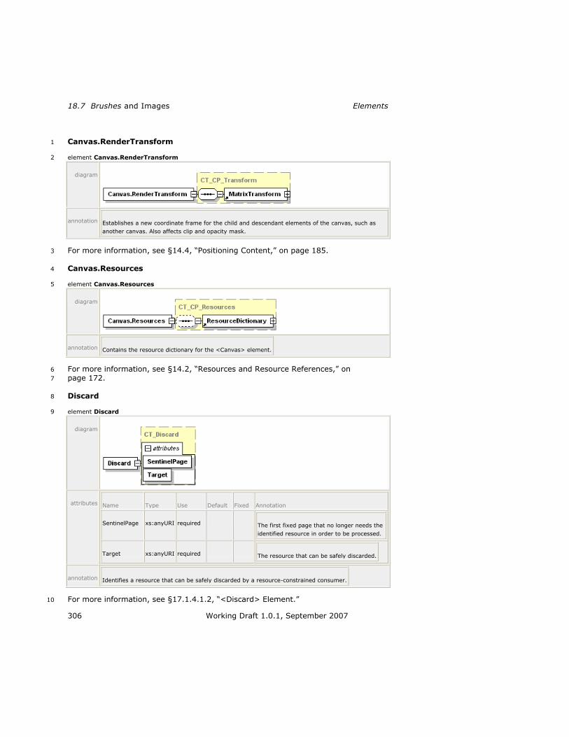
18.7 Brushes and Images Elements
306 Working Draft 1.0.1, September 2007
Canvas.RenderTransform 1
element Canvas.RenderTransform 2
diagram
annotation Establishes a new coordinate frame for the child and descendant elements of the canvas, such as
another canvas. Also affects clip and opacity mask.
For more information, see §14.4, ―Positioning Content,‖ on page 185. 3
Canvas.Resources 4
element Canvas.Resources 5
diagram
annotation Contains the resource dictionary for the <Canvas> element.
For more information, see §14.2, ―Resources and Resource References,‖ on 6
page 172. 7
Discard 8
element Discard 9
diagram
attributes Name Type Use Default Fixed Annotation
SentinelPage xs:anyURI required The first fixed page that no longer needs the
identified resource in order to be processed.
Target xs:anyURI required The resource that can be safely discarded.
annotation Identifies a resource that can be safely discarded by a resource-constrained consumer.
For more information, see §17.1.4.1.2, ―<Discard> Element.‖ 10
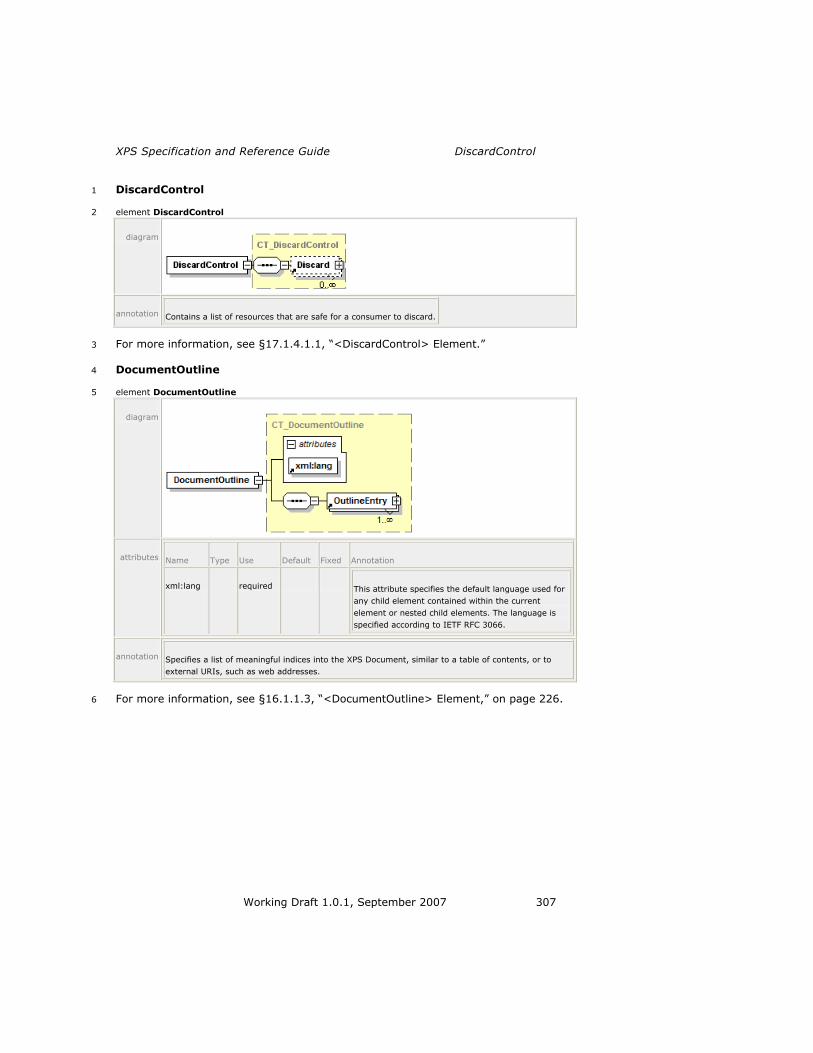
XPS Specification and Reference Guide DiscardControl
Working Draft 1.0.1, September 2007 307
DiscardControl 1
element DiscardControl 2
diagram
annotation Contains a list of resources that are safe for a consumer to discard.
For more information, see §17.1.4.1.1, ―<DiscardControl> Element.‖ 3
DocumentOutline 4
element DocumentOutline 5
diagram
attributes Name Type Use Default Fixed Annotation
xml:lang required This attribute specifies the default language used for
any child element contained within the current
element or nested child elements. The language is
specified according to IETF RFC 3066.
annotation Specifies a list of meaningful indices into the XPS Document, similar to a table of contents, or to
external URIs, such as web addresses.
For more information, see §16.1.1.3, ―<DocumentOutline> Element,‖ on page 226. 6
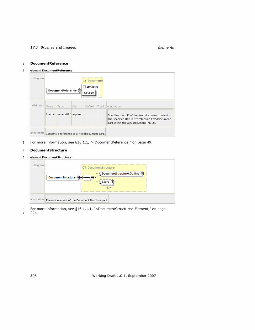
18.7 Brushes and Images Elements
308 Working Draft 1.0.1, September 2007
DocumentReference 1
element DocumentReference 2
diagram
attributes Name Type Use Default Fixed Annotation
Source xs:anyURI required Specifies the URI of the fixed document content.
The specified URI MUST refer to a FixedDocument
part within the XPS Document [M3.2].
annotation Contains a reference to a FixedDocument part.
For more information, see §10.1.1, ―<DocumentReference,‖ on page 49. 3
DocumentStructure 4
element DocumentStructure 5
diagram
annotation The root element of the DocumentStructure part.
For more information, see §16.1.1.1, ―<DocumentStructure> Element,‖ on page 6
224. 7

XPS Specification and Reference Guide DocumentStructure.Outline
Working Draft 1.0.1, September 2007 309
DocumentStructure.Outline 1
element DocumentStructure.Outline 2
diagram
annotation Contains a structured document outline that provides a list of links into the document contents or
external sites.
3
For more information see §16.1.1.2, ―<DocumentStructure.Outline> Element,‖ on 4
page 226. 5
FigureStructure 6
element FigureStructure 7
diagram
annotation Groups the named elements that constitute a single drawing or diagram.
For more information, see §16.1.2.12, ―<FigureStructure> Element,‖ on page 242. 8
FixedDocument 9
element FixedDocument 10
diagram
annotation Binds an ordered sequence of fixed pages together into a single multi-page document.
For more information, see §10.2, ―<FixedDocument> Element,‖ on page 50. 11

18.7 Brushes and Images Elements
310 Working Draft 1.0.1, September 2007
FixedDocumentSequence 1
element FixedDocumentSequence 2
diagram
annotation Specifies a sequence of fixed documents.
For more information, see §10.1, ―<FixedDocumentSequence> Element,‖ on 3
page 49. 4
FixedPage 5
element FixedPage 6
diagram
attributes Name Type Use Default Fixed Annotation
Width ST_GEOne required Width of the page, expressed as a real
number in units of the effective
coordinate space.
Height ST_GEOne required Height of the page, expressed as a real
number in units of the effective
coordinate space.
ContentBox ST_ContentBox Specifies the area of the page

XPS Specification and Reference Guide FixedPage.Resources
Working Draft 1.0.1, September 2007 311
containing imageable content that is to
be fit within the imageable area when
printing or viewing. Contains a list of
four coordinate values (ContentOriginX,
ContentOriginY, ContentWidth,
ContentHeight), expressed as comma-
separated real numbers. Specifying a
value is RECOMMENDED [S3.1]. If
omitted, the default value is
(0,0,Width,Height).
BleedBox ST_BleedBox Specifies the area including crop marks
that extends outside of the physical
page. Contains a list of four coordinate
values (BleedOriginX, BleedOriginY,
BleedWidth, BleedHeight), expressed as
comma-separated real numbers. If
omitted, the default value is
(0,0,Width,Height).
xml:lang required Specifies the default language used for
the current element and for any child or
descendant elements. The language is
specified according to RFC 3066.
Name ST_Name Contains a string value that identifies
the current element as a named,
addressable point in the document for
the purpose of hyperlinking.
annotation Contains markup that describes the rendering of a single page of content.
For more information, see §10.3, ―<FixedPage> Element,‖ on page 53. 1
FixedPage.Resources 2
element FixedPage.Resources 3
diagram
annotation Contains the resource dictionary for the <FixedPage> element.
For more information, see §14.2, ―Resources and Resource References,‖ on 4
page 172. 5

18.7 Brushes and Images Elements
312 Working Draft 1.0.1, September 2007
Glyphs 1 Glyphs 2
element Glyphs 3
diagram
attributes Name Type Use Default Fixed Annotation
BidiLevel 0 Specifies the Unicode
algorithm bidirectional
nesting level. Even
values imply left-to-
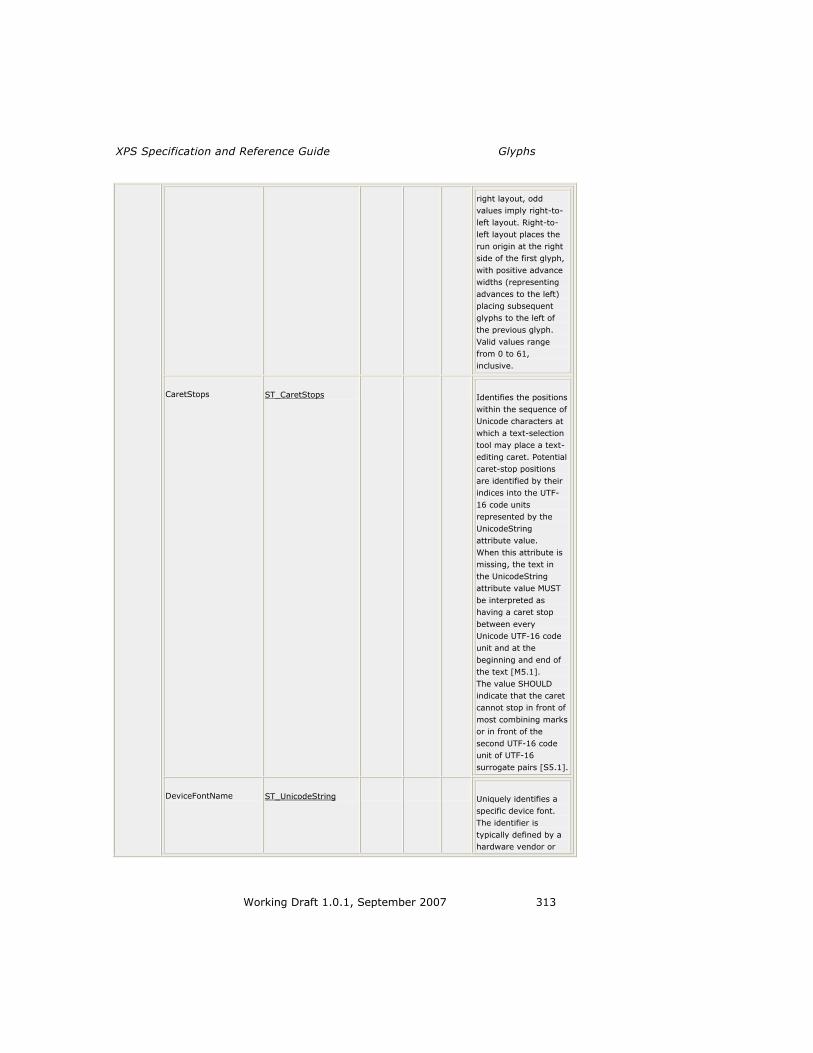
XPS Specification and Reference Guide Glyphs
Working Draft 1.0.1, September 2007 313
right layout, odd
values imply right-to-
left layout. Right-to-
left layout places the
run origin at the right
side of the first glyph,
with positive advance
widths (representing
advances to the left)
placing subsequent
glyphs to the left of
the previous glyph.
Valid values range
from 0 to 61,
inclusive.
CaretStops ST_CaretStops Identifies the positions
within the sequence of
Unicode characters at
which a text-selection
tool may place a text-
editing caret. Potential
caret-stop positions
are identified by their
indices into the UTF-
16 code units
represented by the
UnicodeString
attribute value.
When this attribute is
missing, the text in
the UnicodeString
attribute value MUST
be interpreted as
having a caret stop
between every
Unicode UTF-16 code
unit and at the
beginning and end of
the text [M5.1].
The value SHOULD
indicate that the caret
cannot stop in front of
most combining marks
or in front of the
second UTF-16 code
unit of UTF-16
surrogate pairs [S5.1].
DeviceFontName ST_UnicodeString Uniquely identifies a
specific device font.
The identifier is
typically defined by a
hardware vendor or

18.7 Brushes and Images Elements
314 Working Draft 1.0.1, September 2007
font vendor.
Fill ST_RscRefColor Describes the brush
used to fill the shape
of the rendered
glyphs.
FontRenderingEmSize ST_GEZero required Specifies the font size
in drawing surface
units, expressed as a
float in units of the
effective coordinate
space. A value of 0
results in no visible
text.
FontUri xs:anyURI required The URI of the
physical font from
which all glyphs in the
run are drawn. The
URI MUST reference a
font contained in the
package [M2.1]. If the
physical font
referenced is a
TrueType Collection
(containing multiple
font faces), the
fragment portion of
the URI is a 0-based
index indicating which
font face of the
TrueType Collection
should be used.
OriginX ST_Double required Specifies the x
coordinate of the first
glyph in the run, in
units of the effective
coordinate space. The
glyph is placed so that
the leading edge of its
advance vector and its
baseline intersect with
the point defined by
the OriginX and
OriginY attributes.
OriginY ST_Double required Specifies the y
coordinate of the first
glyph in the run, in
units of the effective

XPS Specification and Reference Guide Glyphs
Working Draft 1.0.1, September 2007 315
coordinate space. The
glyph is placed so that
the leading edge of its
advance vector and its
baseline intersect with
the point defined by
the OriginX and
OriginY attributes.
IsSideways ST_Boolean false Indicates that a glyph
is turned on its side,
with the origin being
defined as the top
center of the unturned
glyph.
Indices ST_Indices Specifies a series of
glyph indices and their
attributes used for
rendering the glyph
run. If the
UnicodeString
attribute specifies an
empty string (―‖ or
―{}‖) and the Indices
attribute is not
specified or is also
empty, a consumer
MUST generate an
error [M5.2].
UnicodeString ST_UnicodeString Contains the string of
text rendered by the
<Glyphs> element.
The text is specified as
Unicode code points.
StyleSimulations ST_StyleSimulations None Specifies a style
simulation. Valid
values are None,
ItalicSimulation,
BoldSimulation, and
BoldItalicSimulation.
RenderTransform ST_RscRefMatrix Establishes a new
coordinate frame for
the glyph run specified
by the <Glyphs>
element. The render
transform affects clip,
opacity mask, fill, x
origin, y origin, the

18.7 Brushes and Images Elements
316 Working Draft 1.0.1, September 2007
actual shape of
individual glyphs, and
the advance widths.
The render transform
also affects the font
size and values
specified in the Indices
attribute.
Clip ST_RscRefAbbrGeomF Limits the rendered
region of the element.
Only portions of the
<Glyphs> element
that fall within the clip
region (even partially
clipped characters)
produce marks on the
page.
Opacity ST_ZeroOne 1.0 Defines the uniform
transparency of the
glyph element. Values
range from 0 (fully
transparent) to 1 (fully
opaque), inclusive.
Values outside of this
range are invalid.
OpacityMask ST_RscRef Specifies a mask of
alpha values that is
applied to the glyphs
in the same fashion as
the Opacity attribute,
but allowing different
alpha values for
different areas of the
element.
Name ST_Name Contains a string
value that identifies
the current element as
a named, addressable
point in the document
for the purpose of
hyperlinking.
FixedPage.NavigateUri xs:anyURI Associates a hyperlink
URI with the element.
May be a relative
reference or a URI
that addresses a
resource that is

XPS Specification and Reference Guide Glyphs.Clip
Working Draft 1.0.1, September 2007 317
internal to or external
to the package.
xml:lang Specifies the default
language used for the
current element. The
language is specified
according to RFC
3066.
x:Key Specifies a name for a
resource in a resource
dictionary. x:Key
MUST be present
when the current
element is defined in a
resource dictionary.
x:Key MUST NOT be
specified outside of a
resource dictionary
[M5.3].
annotation Represents a run of text from a single font.
For more information, see: 1
Section 12.1, ―<Glyphs> Element,‖ on page 98 2
Section 9.1.7, ―Font Parts,‖ on page 31 3
Section 12.1.3, ―Indices Attribute,‖ on page 109 4
Glyphs.Clip 5
element Glyphs.Clip 6
diagram
annotation Limits the rendered region of the element. Only portions of the <Glyphs> element that fall within
the clip region (even partially clipped characters) produce marks on the page.
For more information, see §14.3, ―Clipping,‖ on page 182. 7
Glyphs.Fill 8
element Glyphs.Fill 9

18.7 Brushes and Images Elements
318 Working Draft 1.0.1, September 2007
diagram
annotation Describes the brush used to fill the shape of the rendered glyphs.
For more information, see §12.2, ‖<Glyphs.Fill> Element.‖ 1
Glyphs.OpacityMask 2
element Glyphs.OpacityMask 3
diagram
annotation Specifies a mask of alpha values that is applied to the glyphs in the same fashion as the Opacity
attribute, but allowing different alpha values for different areas of the element.
For more information, see §14.5.3, ―<Glyphs.OpacityMask> Element,‖ on page 202. 4

XPS Specification and Reference Guide Glyphs.RenderTransform
Working Draft 1.0.1, September 2007 319
Glyphs.RenderTransform 1
element Glyphs.RenderTransform 2
diagram
annotation Establishes a new coordinate frame for the glyph run specified by the <Glyphs> element. The
render transform affects clip, opacity mask, fill, x origin, y origin, the actual shape of individual
glyphs, and the advance widths. The render transform also affects the font size and values specified
in the Indices attribute.
For more information, see §14.4, ―Positioning Content,‖ on page 185. 3
GradientStop 4
element GradientStop 5
diagram
attributes Name Type Use Default Fixed Annotation
Color ST_Color required Specifies the gradient stop color. An sRGB color
value specified as a 6-digit hexadecimal number
(#RRGGBB) or an extended color.
Offset ST_Double required Specifies the gradient offset. The offset indicates a
point along the progression of the gradient at
which a color is specified. Colors between gradient
offsets in the progression are interpolated.
annotation Indicates a location and range of color progression for rendering a gradient.
For more information, see §13.7, ―<GradientStop> Element,‖ on page 166. 6
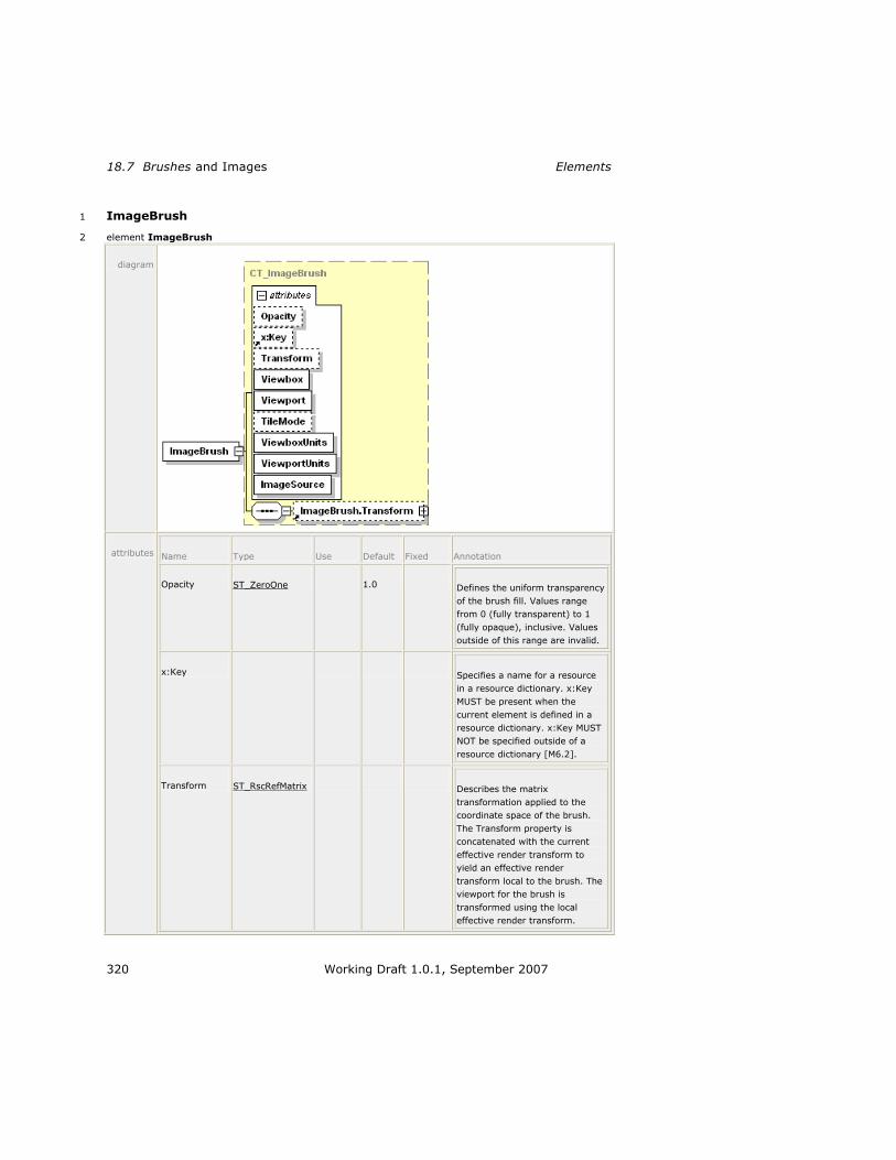
18.7 Brushes and Images Elements
320 Working Draft 1.0.1, September 2007
ImageBrush 1
element ImageBrush 2
diagram
attributes Name Type Use Default Fixed Annotation
Opacity ST_ZeroOne 1.0 Defines the uniform transparency
of the brush fill. Values range
from 0 (fully transparent) to 1
(fully opaque), inclusive. Values
outside of this range are invalid.
x:Key Specifies a name for a resource
in a resource dictionary. x:Key
MUST be present when the
current element is defined in a
resource dictionary. x:Key MUST
NOT be specified outside of a
resource dictionary [M6.2].
Transform ST_RscRefMatrix Describes the matrix
transformation applied to the
coordinate space of the brush.
The Transform property is
concatenated with the current
effective render transform to
yield an effective render
transform local to the brush. The
viewport for the brush is
transformed using the local
effective render transform.

XPS Specification and Reference Guide ImageBrush
Working Draft 1.0.1, September 2007 321
Viewbox ST_ViewBox required Specifies the position and
dimensions of the brush's source
content. Specifies four comma-
separated real numbers (x, y,
Width, Height), where width and
height are non-negative. The
dimensions specified are relative
to the image‘s physical
dimensions expressed in units of
1/96". The corners of the
viewbox are mapped to the
corners of the viewport, thereby
providing the default clipping and
transform for the brush‘s source
content.
Viewport ST_ViewBox required Specifies the region in the
containing coordinate space of
the prime brush tile that is
(possibly repeatedly) applied to
fill the region to which the brush
is applied. Specifies four comma-
separated real numbers (x, y,
Width, Height), where width and
height are non-negative. The
alignment of the brush pattern is
controlled by adjusting the x and
y values.
TileMode ST_TileMode None Specifies how contents will be
tiled in the filled region. Valid
values are None, Tile, FlipX,
FlipY, and FlipXY.
ViewboxUnits ST_ViewUnits required Absolute Specifies the relationship of the
viewbox coordinates to the
containing coordinate space.
ViewportUnits ST_ViewUnits required Absolute Specifies the relationship of the
viewport coordinates to the
containing coordinate space.
ImageSource ST_UriCtxBmp required Specifies the URI of an image
resource or a combination of the
URI of an image resource a color
profile resource. See the Color
clause for important details. The
URI MUST refer to parts in the
package [M2.1].
annotation Fills a region with an image.
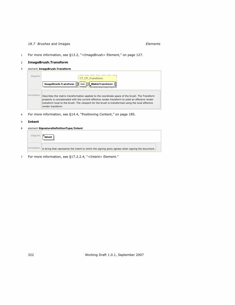
18.7 Brushes and Images Elements
322 Working Draft 1.0.1, September 2007
For more information, see §13.2, ―<ImageBrush> Element,‖ on page 127. 1
ImageBrush.Transform 2
element ImageBrush.Transform 3
diagram
annotation Describes the matrix transformation applied to the coordinate space of the brush. The Transform
property is concatenated with the current effective render transform to yield an effective render
transform local to the brush. The viewport for the brush is transformed using the local effective
render transform.
For more information, see §14.4, ―Positioning Content,‖ on page 185. 4
Intent 5
element SignatureDefinitionType/Intent 6
diagram
annotation A string that represents the intent to which the signing party agrees when signing the document.
For more information, see §17.2.2.4, ―<Intent> Element.‖ 7

XPS Specification and Reference Guide LinearGradientBrush
Working Draft 1.0.1, September 2007 323
LinearGradientBrush 1
element LinearGradientBrush 2
diagram
attributes Name Type Use Default Fixed Annotation
Opacity ST_ZeroOne 1.0 Defines the uniform
transparency of the
linear gradient. Values
range from 0 (fully
transparent) to 1 (fully
opaque), inclusive.
Values outside of this
range are invalid.
x:Key Specifies a name for a
resource in a resource
dictionary. x:Key MUST
be present when the
current element is
defined in a resource
dictionary. x:Key MUST
NOT be specified
outside of a resource
dictionary [M6.5].
ColorInterpolationMode
ST_ClrIntMode
SRgbLinear
Interpolation
Specifies the gamma
function for color
interpolation. The
gamma adjustment
should not be applied to
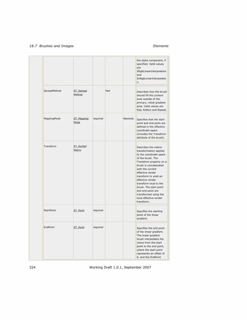
18.7 Brushes and Images Elements
324 Working Draft 1.0.1, September 2007
the alpha component, if
specified. Valid values
are
SRgbLinearInterpolation
and
ScRgbLinearInterpolatio
n.
SpreadMethod ST_Spread
Method Pad Describes how the brush
should fill the content
area outside of the
primary, initial gradient
area. Valid values are
Pad, Reflect and Repeat.
MappingMode ST_Mapping
Mode required
Absolute
Specifies that the start
point and end point are
defined in the effective
coordinate space
(includes the Transform
attribute of the brush).
Transform ST_RscRef
Matrix Describes the matrix
transformation applied
to the coordinate space
of the brush. The
Transform property on a
brush is concatenated
with the current
effective render
transform to yield an
effective render
transform local to the
brush. The start point
and end point are
transformed using the
local effective render
transform.
StartPoint ST_Point required
Specifies the starting
point of the linear
gradient.
EndPoint ST_Point required
Specifies the end point
of the linear gradient.
The linear gradient
brush interpolates the
colors from the start
point to the end point,
where the start point
represents an offset of
0, and the EndPoint

XPS Specification and Reference Guide LinearGradientBrush.GradientStops
Working Draft 1.0.1, September 2007 325
represents an offset of
1. The Offset attribute
value specified in a
GradientStop element
relates to the 0 and 1
offsets defined by the
start point and end
point.
annotatio
n Fills a region with a linear gradient.
For more information, see 1
Section 13.5, ―<LinearGradientBrush> Element,‖ on page 151 2
15, ―Color‖ 3
LinearGradientBrush.GradientStops 4
element LinearGradientBrush.GradientStops 5
diagram
annotation Holds a sequence of GradientStop elements.
For more information, see §13.5.2, ―<LinearGradientBrush.GradientStops> 6
Element,‖ on page 157. 7
LinearGradientBrush.Transform 8
element LinearGradientBrush.Transform 9
diagram
annotation Describes the matrix transformation applied to the coordinate space of the brush. The Transform
property is concatenated with the current effective render transform to yield an effective render
transform local to the brush. The start point and end point are transformed using the local effective
render transform.
For more information, see §14.4.8, ―<LinearGradientBrush.Transform> Element,‖ on 10
page 197. 11
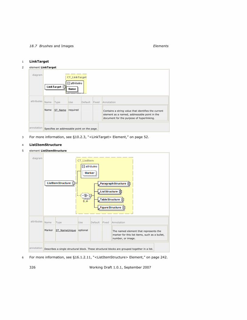
18.7 Brushes and Images Elements
326 Working Draft 1.0.1, September 2007
LinkTarget 1
element LinkTarget 2
diagram
attributes Name Type Use Default Fixed Annotation
Name ST_Name required Contains a string value that identifies the current
element as a named, addressable point in the
document for the purpose of hyperlinking.
annotation Specifies an addressable point on the page.
For more information, see §10.2.3, ―<LinkTarget> Element,‖ on page 52. 3
ListItemStructure 4
element ListItemStructure 5
diagram
attributes Name Type Use Default Fixed Annotation
Marker ST_NameUnique optional The named element that represents the
marker for this list items, such as a bullet,
number, or image.
annotation Describes a single structural block. These structural blocks are grouped together in a list.
For more information, see §16.1.2.11, ―<ListItemStructure> Element,‖ on page 242. 6

XPS Specification and Reference Guide ListStructure
Working Draft 1.0.1, September 2007 327
ListStructure 1
element ListStructure 2
diagram
annotation Contains a collection of items that are group together in a list.
For more information, see §16.1.2.10, ―<ListStructure> Element,‖ on page 241. 3
MatrixTransform 4
element MatrixTransform 5
diagram
attributes Name Type Use Default Fixed Annotation
Matrix ST_Matrix required Specifies the matrix structure that defines the
transformation.
x:Key Specifies a name for a resource in a resource
dictionary. x:Key MUST be present when the
current element is defined in a resource dictionary.
x:Key MUST NOT be specified outside of a
resource dictionary [M7.11].
annotation Creates an arbitrary affine matrix transformation that manipulates objects or coordinate systems in
a two-dimensional plane.
For more information, see §14.4.1, ―<MatrixTransform> Element,‖ on page 185. 6
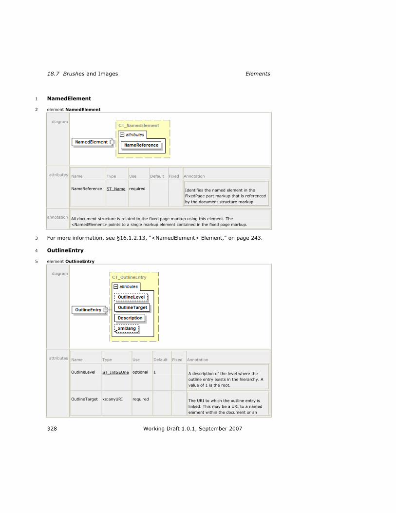
18.7 Brushes and Images Elements
328 Working Draft 1.0.1, September 2007
NamedElement 1
element NamedElement 2
diagram
attributes Name Type Use Default Fixed Annotation
NameReference ST_Name required Identifies the named element in the
FixedPage part markup that is referenced
by the document structure markup.
annotation All document structure is related to the fixed page markup using this element. The
<NamedElement> points to a single markup element contained in the fixed page markup.
For more information, see §16.1.2.13, ―<NamedElement> Element,‖ on page 243. 3
OutlineEntry 4
element OutlineEntry 5
diagram
attributes Name Type Use Default Fixed Annotation
OutlineLevel ST_IntGEOne optional 1 A description of the level where the
outline entry exists in the hierarchy. A
value of 1 is the root.
OutlineTarget xs:anyURI required The URI to which the outline entry is
linked. This may be a URI to a named
element within the document or an

XPS Specification and Reference Guide PageContent
Working Draft 1.0.1, September 2007 329
external URI, such as a website. It can
be used as a hyperlink destination.
Description xs:string required The friendly text associated with this
outline entry.
xml:lang optional This attribute specifies the default
language used for any child element
contained within the current element or
nested child elements. The language is
specified according to IETF RFC 3066.
annotation Represents an index to a specific location in the document.
For more information, see §16.1.1.4, ―<OutlineEntry> Element,‖ on page 227. 1
PageContent 2
element PageContent 3
diagram
attributes Name Type Use Default Fixed Annotation
Source xs:anyURI required Specifies a URI that refers to the page content,
held in a distinct part within the package. The
content identified MUST be a FixedPage part
within the XPS Document [M3.5].
Width ST_GEOne Typical width of pages contained in the page
content.
Height ST_GEOne Typical height of pages contained in the page
content.
annotation Defines a reference from a fixed document to a part that contains a <FixedPage> element.
For more information, see §10.2.1, ―<PageContent> Element,‖ on page 50. 4

18.7 Brushes and Images Elements
330 Working Draft 1.0.1, September 2007
PageContent.LinkTargets 1
element PageContent.LinkTargets 2
diagram
annotation Contains a collection of <LinkTarget> elements, each of which is addressable via hyperlink.
For more information, see §10.2.2, ―<PageContent.LinkTargets> Element,‖ on 3
page 51. 4
ParagraphStructure 5
element ParagraphStructure 6
diagram
annotation Contains the named elements that constitute a single paragraph.
For more information, see §16.1.2.5, ―<ParagraphStructure> Element,‖ on page 7
239. 8

XPS Specification and Reference Guide Path
Working Draft 1.0.1, September 2007 331
Path 1
element Path 2
diagram
attributes Name Type Use Default Fixed Annotation

18.7 Brushes and Images Elements
332 Working Draft 1.0.1, September 2007
Data ST_RscRefAbbrGeomF Describes the
geometry of the
path.
Fill ST_RscRefColor Describes the
brush used to
paint the
geometry specified
by the Data
property of the
path.
RenderTransform ST_RscRefMatrix Establishes a new
coordinate frame
for all attributes of
the path and for
all child elements
of the path, such
as the geometry
defined by the
<Path.Data>
property element.
Clip ST_RscRefAbbrGeomF Limits the
rendered region of
the element.
Opacity ST_ZeroOne 1.0 Defines the
uniform
transparency of
the path element.
Values range from
0 (fully
transparent) to 1
(fully opaque),
inclusive. Values
outside of this
range are invalid.
OpacityMask ST_RscRef Specifies a mask
of alpha values
that is applied to
the path in the
same fashion as
the Opacity
attribute, but
allowing different
alpha values for
different areas of
the element.

XPS Specification and Reference Guide Path
Working Draft 1.0.1, September 2007 333
Stroke ST_RscRefColor Specifes the brush
used to draw the
stroke.
StrokeDashArray ST_EvenArrayPos Specifies the
length of dashes
and gaps of the
outline stroke.
These values are
specified as
multiples of the
stroke thickness
as a space-
separated list with
an even number of
non-negative
values. When a
stroke is drawn,
the dashes and
gaps specified by
these values are
repeated to cover
the length of the
stroke. If this
attribute is
omitted, the
stroke is drawn
solid, without any
gaps.
StrokeDashCap ST_DashCap Flat Specifies how the
ends of each dash
are drawn. Valid
values are Flat,
Round, Square,
and Triangle.
StrokeDashOffset ST_Double 0.0 Adjusts the start
point for repeating
the dash array
pattern. If this
value is omitted,
the dash array
aligns with the
origin of the
stroke. Values are
specified as
multiples of the
stroke thickness.
StrokeEndLineCap ST_LineCap Flat Defines the shape
of the end of the

18.7 Brushes and Images Elements
334 Working Draft 1.0.1, September 2007
last dash in a
stroke. Valid
values are Flat,
Square, Round,
and Triangle.
StrokeStartLineCap ST_LineCap Flat Defines the shape
of the beginning of
the first dash in a
stroke. Valid
values are Flat,
Square, Round,
and Triangle.
StrokeLineJoin ST_LineJoin Miter Specifies how a
stroke is drawn at
a corner of a path.
Valid values are
Miter, Bevel, and
Round. If Miter is
selected, the value
of
StrokeMiterLimit is
used in drawing
the stroke.
StrokeMiterLimit ST_GEOne 10.0 The ratio between
the maximum
miter length and
half of the stroke
thickness. This
value is significant
only if the
StrokeLineJoin
attribute specifies
Miter.
StrokeThickness ST_GEZero 1.0 Specifies the
thickness of a
stroke, in units of
the effective
coordinate space
(includes the
path's render
transform). The
stroke is drawn on
top of the
boundary of the
geometry specified
by the <Path>
element‘s Data
property. Half of
the

XPS Specification and Reference Guide Path
Working Draft 1.0.1, September 2007 335
StrokeThickness
extends outside of
the geometry
specified by the
Data property and
the other half
extends inside of
the geometry.
Name ST_Name Contains a string
value that
identifies the
current element as
a named,
addressable point
in the document
for the purpose of
hyperlinking.
FixedPage.NavigateUri xs:anyURI Associates a
hyperlink URI with
the element. Can
be a relative
reference or a URI
that addresses a
resource that is
internal to or
external to the
package.
xml:lang Specifies the
default language
used for the
current element
and for any child
or descendant
elements. The
language is
specified according
to RFC 3066.
x:Key Specifies a name
for a resource in a
resource
dictionary. x:Key
MUST be present
when the current
element is defined
in a resource
dictionary. x:Key
MUST NOT be
specified outside
of a resource

18.7 Brushes and Images Elements
336 Working Draft 1.0.1, September 2007
dictionary [M4.1].
AutomationProperties.Name xs:string A brief description
of the <Path> for
accessibility
purposes,
particularly if filled
with an
<ImageBrush>.
AutomationProperties.HelpText xs:string A detailed
description of the
<Path> for
accessibility
purposes,
particularly if filled
with an
<ImageBrush>.
SnapsToDevicePixels ST_Boolean On Anti-aliasing
consumers
controls if control
points snap to the
nearest device
pixels. Valid
values are ‗false‘
and ‗true‘.
Consumers MAY
ignore this
attribute [O4.1].
annotation Defines a single graphical effect to be rendered to the page. It paints a geometry with a brush and
draws a stroke around it.
For more information, see 1
Section 11.1, ―<Path> Element,‖ on page 68 2
Section 11.2.3, ―Abbreviated Geometry Syntax,‖ on page 90 3
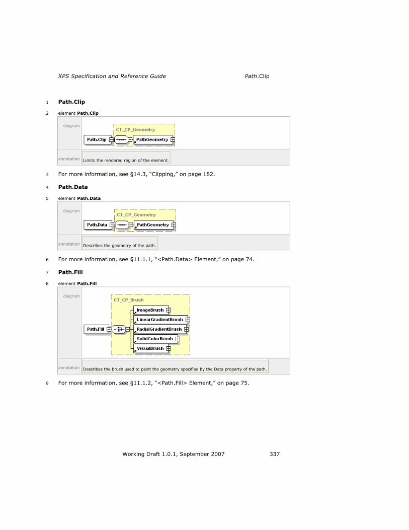
XPS Specification and Reference Guide Path.Clip
Working Draft 1.0.1, September 2007 337
Path.Clip 1
element Path.Clip 2
diagram
annotation Limits the rendered region of the element.
For more information, see §14.3, ―Clipping,‖ on page 182. 3
Path.Data 4
element Path.Data 5
diagram
annotation Describes the geometry of the path.
For more information, see §11.1.1, ―<Path.Data> Element,‖ on page 74. 6
Path.Fill 7
element Path.Fill 8
diagram
annotation Describes the brush used to paint the geometry specified by the Data property of the path.
For more information, see §11.1.2, ―<Path.Fill> Element,‖ on page 75. 9

18.7 Brushes and Images Elements
338 Working Draft 1.0.1, September 2007
Path.OpacityMask 1
element Path.OpacityMask 2
diagram
annotation Specifies the mask of alpha values that is applied to the path in the same fashion as the Opacity
attribute, but allowing different alpha values for different areas of the element.
For more information, see §14.5.2, ―<Path.OpacityMask,‖ on page 201. 3
Path.RenderTransform 4
element Path.RenderTransform 5
diagram
annotation Establishes a new coordinate frame for all attributes of the path and for all child elements of the
path, such as the geometry defined by the <Path.Data> property element.
For more information, see §14.4, ―Positioning Content,‖ on page 185. 6
Path.Stroke 7
element Path.Stroke 8
diagram
annotation Specifies the brush used to draw the stroke.
9

XPS Specification and Reference Guide PathFigure
Working Draft 1.0.1, September 2007 339
For more information, see §11.1.3, ―<Path.Stroke> Element,‖ on page 76. 1
PathFigure 2
element PathFigure 3
diagram
attributes Name Type Use Default Fixed Annotation
IsClosed ST_Boolean false Specifies whether the path is closed. If set to
true, the stroke is drawn "closed," that is, the
last point in the last segment of the path
figure is connected with the point specified in
the StartPoint attribute, otherwise the stroke
is drawn "open," and the last point is not
connected to the start point. Only applicable
if the path figure is used in a <Path>
element that specifies a stroke.
StartPoint ST_Point required Specifies the starting point for the first
segment of the path figure.
IsFilled ST_Boolean true Specifies whether the path figure is used in
computing the area of the containing path
geometry. Can be true or false. When set to
false, the path figure is considered only for
stroking.
annotation Specifies a set of one or more segment elements defining a closed region.
For more information, see §11.2.2.1, ―<PathFigure> Element.‖ 4
PathGeometry 5
element PathGeometry 6
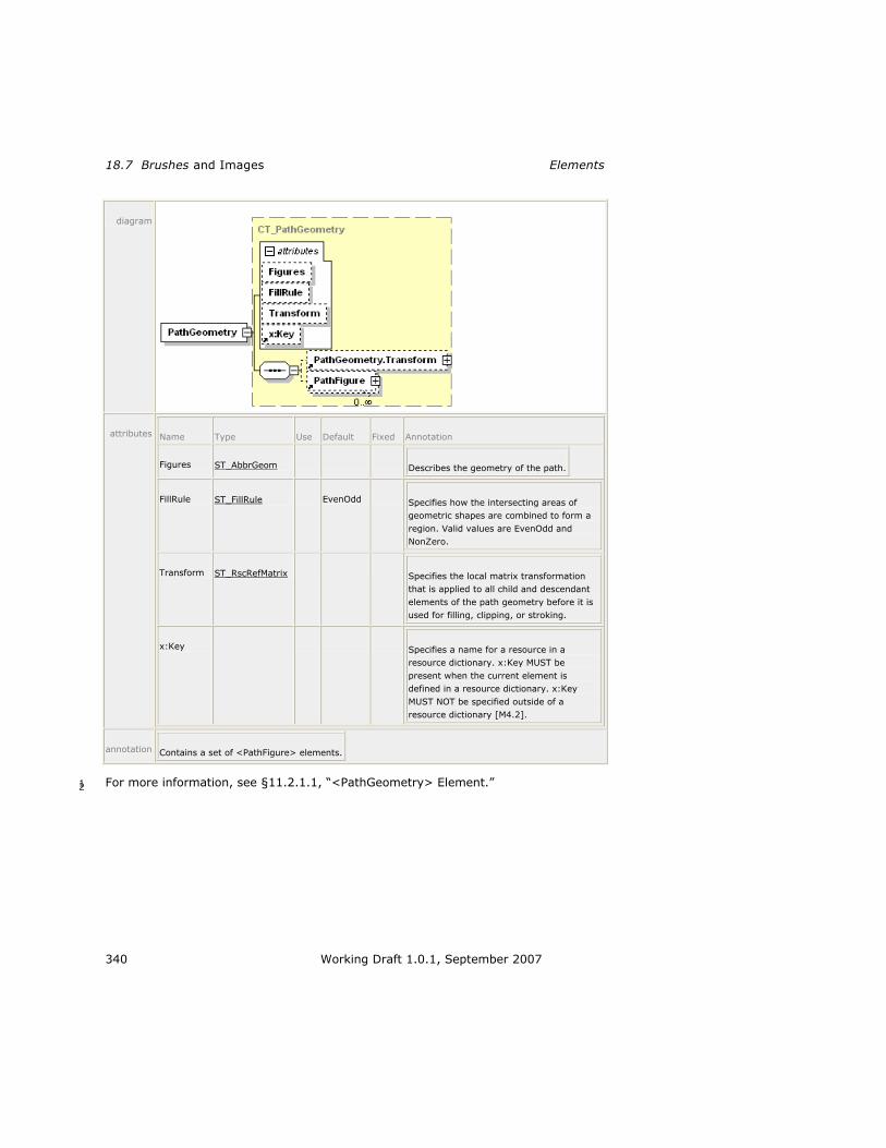
18.7 Brushes and Images Elements
340 Working Draft 1.0.1, September 2007
diagram
attributes Name Type Use Default Fixed Annotation
Figures ST_AbbrGeom Describes the geometry of the path.
FillRule ST_FillRule EvenOdd Specifies how the intersecting areas of
geometric shapes are combined to form a
region. Valid values are EvenOdd and
NonZero.
Transform ST_RscRefMatrix Specifies the local matrix transformation
that is applied to all child and descendant
elements of the path geometry before it is
used for filling, clipping, or stroking.
x:Key Specifies a name for a resource in a
resource dictionary. x:Key MUST be
present when the current element is
defined in a resource dictionary. x:Key
MUST NOT be specified outside of a
resource dictionary [M4.2].
annotation Contains a set of <PathFigure> elements.
For more information, see §11.2.1.1, ―<PathGeometry> Element.‖ 1 2

XPS Specification and Reference Guide PathGeometry.Transform
Working Draft 1.0.1, September 2007 341
PathGeometry.Transform 1
element PathGeometry.Transform 2
diagram
annotation Specifies the local matrix transformation that is applied to all child and descendant elements of the
path geometry before it is used for filling, clipping, or stroking.
For more information, see §14.4.5, ―<PathGeometry.Transform> Element,‖ on 3
page 192. 4
PolyBezierSegment 5
element PolyBezierSegment 6
diagram
attributes Name Type Use Default Fixed Annotation
Points ST_Points required Specifies control points for multiple Bézier
segments. Coordinate values within each pair
are comma-separated and additional
whitespace may appear. Coordinate pairs are
separated from other coordinate pairs by
whitespace.
IsStroked ST_Boolean true Specifies whether the stroke for this segment
of the path is drawn. Can be true or false.
annotation A series of Bézier segments.
7

18.7 Brushes and Images Elements
342 Working Draft 1.0.1, September 2007
PolyLineSegment 1
element PolyLineSegment 2
diagram
attributes Name Type Use Default Fixed Annotation
Points ST_Points required Specifies a set of coordinates for the multiple
segments that define the poly line segment.
Coordinate values within each pair are
comma-separated and additional whitespace
may appear. Coordinate pairs are separated
from other coordinate pairs by whitespace.
IsStroked ST_Boolean true Specifies whether the stroke for this segment
of the path is drawn. Can be true or false.
annotation Specifies a set of points between which lines are drawn.
3
PolyQuadraticBezierSegment 4
element PolyQuadraticBezierSegment 5
diagram
attributes Name Type Use Default Fixed Annotation
Points ST_Points required Specifies control points for multiple quadratic
Bézier segments. Coordinate values within
each pair are comma-separated and
additional whitespace may appear.
Coordinate pairs are separated from other
coordinate pairs by whitespace.
IsStroked ST_Boolean true Specifies whether the stroke for this segment
of the path is drawn. Can be true or false.

XPS Specification and Reference Guide RadialGradientBrush
Working Draft 1.0.1, September 2007 343
annotation A series of quadratic Bézier segments.
1
RadialGradientBrush 2
element RadialGradientBrush 3
diagram
attributes Name Type Use Default Fixed Annotation
Opacity ST_ZeroOne 1.0 Defines the uniform
transparency of the
radial gradient. Values
range from 0 (fully
transparent) to 1 (fully
opaque), inclusive.
Values outside of this
range are invalid.
x:Key Specifies a name for a
resource in a resource
dictionary. x:Key MUST
be present when the
current element is
defined in a resource
dictionary. x:Key MUST
NOT be specified
outside of a resource
dictionary [M6.6].
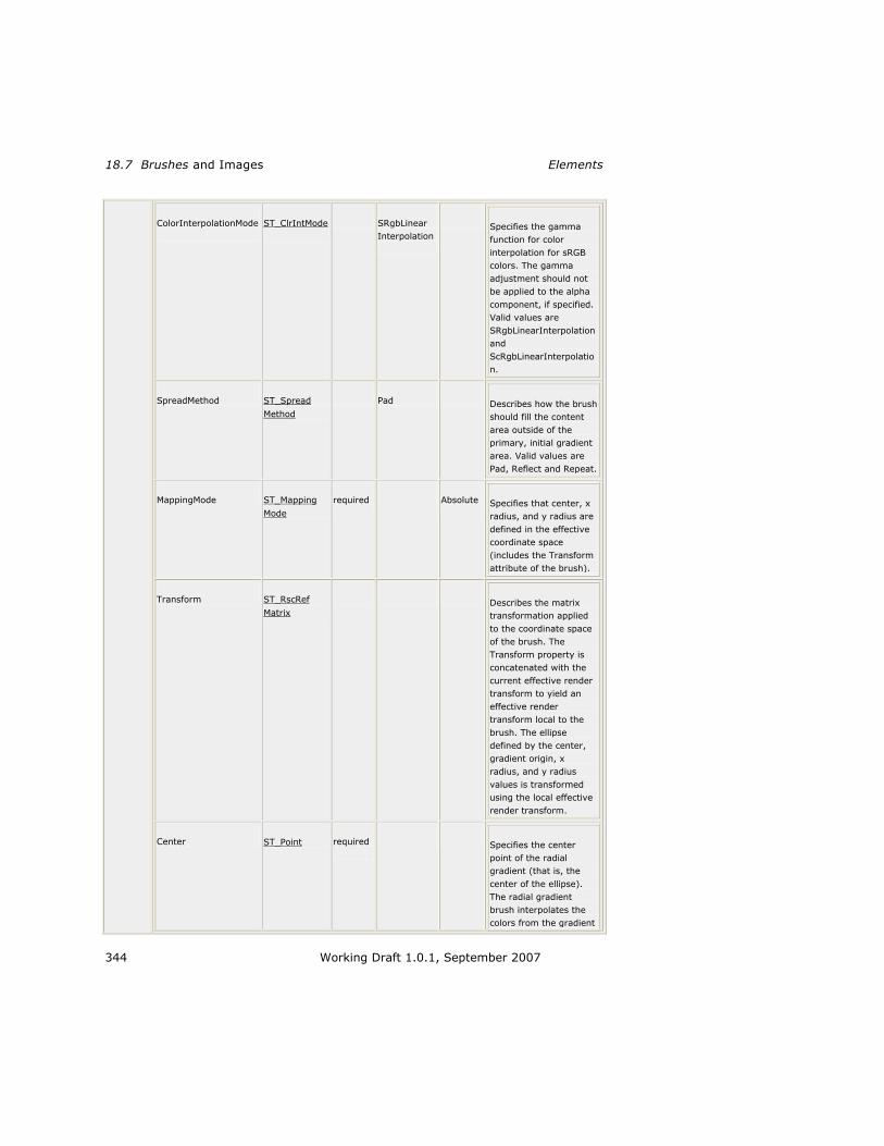
18.7 Brushes and Images Elements
344 Working Draft 1.0.1, September 2007
ColorInterpolationMode
ST_ClrIntMode
SRgbLinear
Interpolation
Specifies the gamma
function for color
interpolation for sRGB
colors. The gamma
adjustment should not
be applied to the alpha
component, if specified.
Valid values are
SRgbLinearInterpolation
and
ScRgbLinearInterpolatio
n.
SpreadMethod ST_Spread
Method Pad Describes how the brush
should fill the content
area outside of the
primary, initial gradient
area. Valid values are
Pad, Reflect and Repeat.
MappingMode ST_Mapping
Mode required
Absolute
Specifies that center, x
radius, and y radius are
defined in the effective
coordinate space
(includes the Transform
attribute of the brush).
Transform ST_RscRef
Matrix Describes the matrix
transformation applied
to the coordinate space
of the brush. The
Transform property is
concatenated with the
current effective render
transform to yield an
effective render
transform local to the
brush. The ellipse
defined by the center,
gradient origin, x
radius, and y radius
values is transformed
using the local effective
render transform.
Center ST_Point required
Specifies the center
point of the radial
gradient (that is, the
center of the ellipse).
The radial gradient
brush interpolates the
colors from the gradient

XPS Specification and Reference Guide RadialGradientBrush.GradientStops
Working Draft 1.0.1, September 2007 345
origin to the
circumference of the
ellipse. The
circumference is
determined by the
center and the radii.
GradientOrigin ST_Point required
Specifies the origin
point of the radial
gradient.
RadiusX ST_GEZero required
Specifies the radius in
the x dimension of the
ellipse which defines the
radial gradient.
RadiusY ST_GEZero required
Specifies the radius in
the y dimension of the
ellipse which defines the
radial gradient.
annotatio
n Fills a region with a radial gradient.
For more information, see: 1
Section 13.6, ―<RadialGradientBrush> Element,‖ on page 158 2
15, ―Color‖ 3
RadialGradientBrush.GradientStops 4
element RadialGradientBrush.GradientStops 5
diagram
annotation Holds a sequence of <GradientStop> elements.
For more information, see §13.6.2, ―<RadialGradientBrush.GradientStops> 6
Element,‖ on page 165. 7
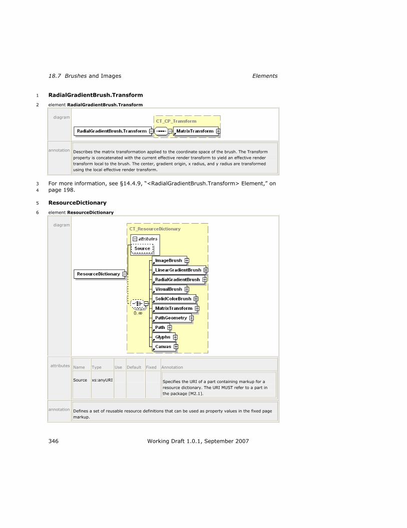
18.7 Brushes and Images Elements
346 Working Draft 1.0.1, September 2007
RadialGradientBrush.Transform 1
element RadialGradientBrush.Transform 2
diagram
annotation Describes the matrix transformation applied to the coordinate space of the brush. The Transform
property is concatenated with the current effective render transform to yield an effective render
transform local to the brush. The center, gradient origin, x radius, and y radius are transformed
using the local effective render transform.
For more information, see §14.4.9, ―<RadialGradientBrush.Transform> Element,‖ on 3
page 198. 4
ResourceDictionary 5
element ResourceDictionary 6
diagram
attributes Name Type Use Default Fixed Annotation
Source xs:anyURI Specifies the URI of a part containing markup for a
resource dictionary. The URI MUST refer to a part in
the package [M2.1].
annotation Defines a set of reusable resource definitions that can be used as property values in the fixed page
markup.

XPS Specification and Reference Guide ResourceDictionary
Working Draft 1.0.1, September 2007 347
For more information, see §14.2, ―Resources and Resource References,‖ on 1
page 172. 2

18.7 Brushes and Images Elements
348 Working Draft 1.0.1, September 2007
SectionStructure 1
element SectionStructure 2
diagram
annotation Provides an arbitrary grouping of content structural markup elements.
For more information, see §16.1.2.4, ―<SectionStructure> Element,‖ on page 239. 3
SignBy 4
element SignatureDefinitionType/SignBy 5
diagram
annotation The date and time by which the requested party is to sign the XPS Document.
For more information, see §17.2.2.5, ―<SignBy> Element.‖ 6
SignatureDefinition 7
element SignatureDefinitionsType/SignatureDefinition 8
diagram
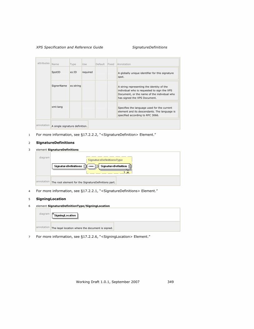
XPS Specification and Reference Guide SignatureDefinitions
Working Draft 1.0.1, September 2007 349
attributes Name Type Use Default Fixed Annotation
SpotID xs:ID required A globally unique identifier for this signature
spot.
SignerName xs:string A string representing the identity of the
individual who is requested to sign the XPS
Document, or the name of the individual who
has signed the XPS Document.
xml:lang Specifies the language used for the current
element and its descendants. The language is
specified according to RFC 3066.
annotation A single signature definition.
For more information, see §17.2.2.2, ―<SignatureDefinition> Element.‖ 1
SignatureDefinitions 2
element SignatureDefinitions 3
diagram
annotation The root element for the SignatureDefinitions part.
For more information, see §17.2.2.1, ―<SignatureDefinitions> Element.‖ 4
SigningLocation 5
element SignatureDefinitionType/SigningLocation 6
diagram
annotation The legal location where the document is signed.
For more information, see §17.2.2.6, ―<SigningLocation> Element.‖ 7

18.7 Brushes and Images Elements
350 Working Draft 1.0.1, September 2007
SolidColorBrush 1
element SolidColorBrush 2
diagram
attributes Name Type Use Default Fixed Annotation
Opacity ST_ZeroOne 1.0 Defines the uniform transparency of the brush
fill. Values range from 0 (fully transparent) to
1 (fully opaque), inclusive. Values outside of
this range are invalid.
x:Key Specifies a name for a resource in a resource
dictionary. x:Key MUST be present when the
current element is defined in a resource
dictionary. x:Key MUST NOT be specified
outside of a resource dictionary [M6.1].
Color ST_Color required Specifies the color for filled elements. An sRGB
color value specified as a 6-digit hexadecimal
number (#RRGGBB) or an extended color.
annotation Fills defined geometric regions with a solid color.
For more information, see §13.1, ―<SolidColorBrush,‖ on page 126. 3
SpotLocation 4
element SignatureDefinitionType/SpotLocation 5
diagram

XPS Specification and Reference Guide Story
Working Draft 1.0.1, September 2007 351
attributes Name Type Use Default Fixed Annotation
PageURI xs:anyURI required Specifies the page on which the signature spot
should be displayed.
StartX xs:double required Specifies the x coordinate of the origin point
(upper-left corner) on the page where the
signature spot should be displayed.
StartY xs:double required Specifies the y coordinate of the origin point
(upper-left corner) on the page where the
signature spot should be displayed.
annotation Specifies where a consumer should place a signature spot.
For more information, see §17.2.2.3, ―<SpotLocation> Element.‖ 1
Story 2
element Story 3
diagram
attributes Name Type Use Default Fixed Annotation
StoryName xs:string required The name used by story fragments to identify
they belong to this story.
annotation Defines a single story and where each of its story fragments appear in the XPS Document.
For more information, see §16.1.1.5, ―<Story> Element,‖ on page 228. 4

18.7 Brushes and Images Elements
352 Working Draft 1.0.1, September 2007
StoryBreak 1
element StoryBreak 2
diagram
annotation If located at the beginning of a <StoryFragment> definition, indicates that the following markup
elements should not be merged with the markup from the previous <StoryFragment>. If located at
the end of a <StoryFragment> definition, indicates that the preceding markup elements should not
be merged with the subsequent <StoryFragment>.
For more information, see §16.1.2.3, ―<StoryBreak> Element,‖ on page 239. 3
StoryFragment 4
element StoryFragment 5
diagram
attributes Name Type Use Default Fixed Annotation
StoryName xs:string optional Identifies the story that this story
fragment belongs to. If omitted,
the story fragment is not
associated with any story.

XPS Specification and Reference Guide StoryFragments
Working Draft 1.0.1, September 2007 353
FragmentName xs:string optional Used to uniquely identify the
story fragment.
FragmentType ST_FragmentType required Specifies the type of content
included in the story fragment.
Valid values are Content, Header,
and Footer.
annotation Specifies the document structural markup that appears on the current page for a single story block.
For more information, see §16.1.2.2, ―<StoryFragment> Element,‖ on page 235. 1
StoryFragments 2
element StoryFragments 3
diagram
annotation The root of a StoryFragments part. Contains all story fragments that appear on a specific page.
For more information, see §16.1.2.1, ―<StoryFragments> Element,‖ on page 234. 4
StoryFragmentReference 5
element StoryFragmentReference 6
diagram
attributes Name Type Use Default Fixed Annotation
FragmentName xs:string optional Used to distingush between multiple
story fragments from the same story
on a single page.
Page ST_IntGEOne required Identifies the page number of the
document that the story fragment is
related to. Page numbers start at 1
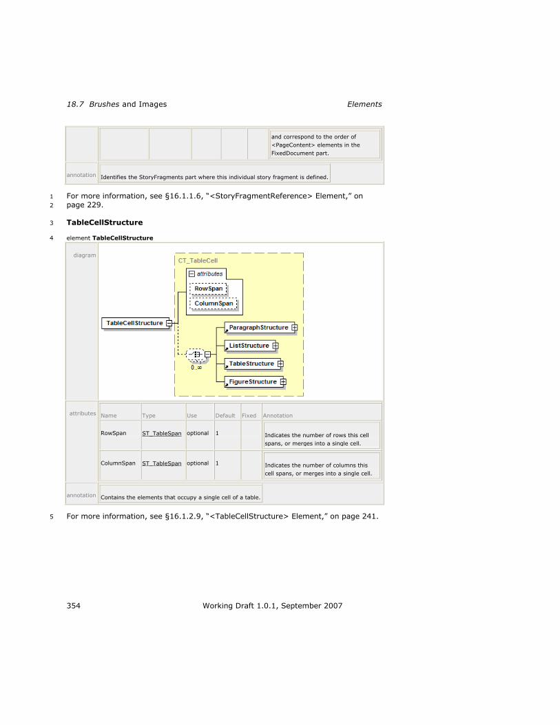
18.7 Brushes and Images Elements
354 Working Draft 1.0.1, September 2007
and correspond to the order of
<PageContent> elements in the
FixedDocument part.
annotation Identifies the StoryFragments part where this individual story fragment is defined.
For more information, see §16.1.1.6, ―<StoryFragmentReference> Element,‖ on 1
page 229. 2
TableCellStructure 3
element TableCellStructure 4
diagram
attributes Name Type Use Default Fixed Annotation
RowSpan ST_TableSpan optional 1 Indicates the number of rows this cell
spans, or merges into a single cell.
ColumnSpan ST_TableSpan optional 1 Indicates the number of columns this
cell spans, or merges into a single cell.
annotation Contains the elements that occupy a single cell of a table.
For more information, see §16.1.2.9, ―<TableCellStructure> Element,‖ on page 241. 5
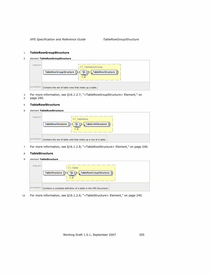
XPS Specification and Reference Guide TableRowGroupStructure
Working Draft 1.0.1, September 2007 355
TableRowGroupStructure 1
element TableRowGroupStructure 2
diagram
annotation Contains the set of table rows that make up a table.
For more information, see §16.1.2.7, ―<TableRowGroupStructure> Element,‖ on 3
page 240. 4
TableRowStructure 5
element TableRowStructure 6
diagram
annotation Contains the set of table cells that make up a row of a table.
For more information, see §16.1.2.8, ―<TableRowStructure> Element,‖ on page 240. 7
TableStructure 8
element TableStructure 9
diagram
annotation Contains a complete definition of a table in the XPS Document.
For more information, see §16.1.2.6, ―<TableStructure> Element,‖ on page 240. 10

18.7 Brushes and Images Elements
356 Working Draft 1.0.1, September 2007
VisualBrush 1
element VisualBrush 2
diagram
attributes Name Type Use Default Fixed Annotation
Opacity ST_ZeroOne 1.0 Defines the uniform transparency
of the brush fill. Values range
from 0 (fully transparent) to 1
(fully opaque), inclusive. Values
outside of this range are invalid.
x:Key Specifies a name for a resource
in a resource dictionary. x:Key
MUST be present when the
current element is defined in a
resource dictionary. x:Key MUST
NOT be specified outside of a
resource dictionary [M6.4].
Transform ST_RscRefMatrix Describes the matrix
transformation applied to the
coordinate space of the brush.
The Transform property is
concatenated with the current
effective render transform to
yield an effective render
transform local to the brush. The
viewport for the brush is
transformed using that local

XPS Specification and Reference Guide VisualBrush
Working Draft 1.0.1, September 2007 357
effective render transform.
Viewbox ST_ViewBox required Specifies the position and
dimensions of the brush's source
content. Specifies four comma-
separated real numbers (x, y,
Width, Height), where width and
height are non-negative. The
viewbox defines the default
coordinate system for the
element specified in the
<VisualBrush.Visual> property
element. The corners of the
viewbox are mapped to the
corners of the viewport, thereby
providing the default clipping and
transform for the brush‘s source
content.
Viewport ST_ViewBox required Specifies the region in the
containing coordinate space of
the prime brush tile that is
(possibly repeatedly) applied to
fill the region to which the brush
is applied. Specifies four comma-
separated real numbers (x, y,
Width, Height), where width and
height are non-negative. The
alignment of the brush pattern is
controlled by adjusting the x and
y values.
TileMode ST_TileMode None Specifies how contents will be
tiled in the filled region. Valid
values are None, Tile, FlipX,
FlipY, and FlipXY.
ViewboxUnits ST_ViewUnits required Absolute Specifies the relationship of the
viewbox coordinates to the
containing coordinate space.
ViewportUnits ST_ViewUnits required Absolute Specifies the relationship of the
viewport coordinates to the
containing coordinate space.
Visual ST_RscRef Specifies resource reference to a
<Path>, <Glyphs>, or
<Canvas> element defined in a
resource dictionary and used to
draw the brush‘s source content.

18.7 Brushes and Images Elements
358 Working Draft 1.0.1, September 2007
annotation Fills a region with a drawing. The drawing may be specified as either a child of the <VisualBrush>
element, or as a resource reference. Drawing content is expressed using <Canvas>, <Path>, and
<Glyphs> elements.
For more information, see §13.3, ―<VisualBrush> Element,‖ on page 131. 1
VisualBrush.Transform 2
element VisualBrush.Transform 3
diagram
annotation Describes the matrix transformation applied to the coordinate space of the brush. The Transform
property is concatenated with the current effective render transform to yield an effective render
transform local to the brush. The viewport for the brush is transformed using the local effective
render transform.
For more information, see §14.4, ―Positioning Content,‖ on page 185. 4
VisualBrush.Visual 5
element VisualBrush.Visual 6
diagram
annotation Specifies a <Path> element, <Glyphs> element, or <Canvas> element used to draw the brush‘s
source contents.
7
8
9

XPS Specification and Reference Guide A
Working Draft 1.0.1, September 2007 359
A. Signature Definitions Schema 1
<?xml version="1.0" encoding="utf-8"?> 2
<xs:schema targetNamespace="http://schemas.microsoft.com/xps/2005/06/signature-3
definitions" xmlns="http://schemas.microsoft.com/xps/2005/06/signature-4
definitions" xmlns:xs="http://www.w3.org/2001/XMLSchema" 5
elementFormDefault="qualified" blockDefault="#all"> 6
7
<xs:import namespace="http://www.w3.org/XML/1998/namespace" /> 8
9
<xs:complexType name="SignatureDefinitionsType"> 10
<xs:sequence> 11
<xs:element name="SignatureDefinition" 12
type="SignatureDefinitionType" minOccurs="1" maxOccurs="unbounded"> 13
</xs:element> 14
</xs:sequence> 15
</xs:complexType> 16
17
<xs:complexType name="SpotLocationType"> 18
<xs:attribute name="PageURI" type="xs:anyURI" use="required"> 19
</xs:attribute> 20
<xs:attribute name="StartX" type="xs:double" use="required"> 21
</xs:attribute> 22
<xs:attribute name="StartY" type="xs:double" use="required"> 23
</xs:attribute> 24
</xs:complexType> 25
26
<xs:complexType name="SignatureDefinitionType"> 27
<xs:sequence> 28
<xs:element name="SpotLocation" type="SpotLocationType" 29
minOccurs="0"> 30
</xs:element> 31
<xs:element name="Intent" type="xs:string" minOccurs="0"> 32
</xs:element> 33
<xs:element name="SignBy" type="xs:dateTime" minOccurs="0"> 34
</xs:element> 35
<xs:element name="SigningLocation" type="xs:string" minOccurs="0"> 36
</xs:element> 37
</xs:sequence> 38
<xs:attribute name="SpotID" type="xs:ID" use="required"> 39
</xs:attribute> 40
<xs:attribute name="SignerName" type="xs:string"> 41
</xs:attribute> 42
<xs:attribute ref="xml:lang"> 43
</xs:attribute> 44
</xs:complexType> 45
46
<xs:element name="SignatureDefinitions" type="SignatureDefinitionsType"> 47
</xs:element> 48
</xs:schema> 49
50


XPS Specification and Reference Guide B
Working Draft 1.0.1, September 2007 361
B. XPS Document Schema 1
<?xml version="1.0" encoding="utf-8"?> 2
<xs:schema targetNamespace="http://schemas.microsoft.com/xps/2005/06" 3
xmlns="http://schemas.microsoft.com/xps/2005/06" 4
xmlns:mstns="http://tempuri.org/XMLSchema.xsd" 5
xmlns:xs="http://www.w3.org/2001/XMLSchema" 6
xmlns:x="http://schemas.microsoft.com/xps/2005/06/resourcedictionary-key" 7
elementFormDefault="qualified" blockDefault="#all"> 8
9
<xs:import 10
namespace="http://schemas.microsoft.com/xps/2005/06/resourcedictionary-key" /> 11
<xs:import namespace="http://www.w3.org/XML/1998/namespace" /> 12
13
<!-- Names used for types and groups: 14
15
ST_* simpleType 16
CT_* complexType 17
G_* group 18
AG_* attributeGroup 19
20
--> 21
22
<!-- Individual real number patterns 23
All patterns using numbers now use <whitespace value="collapse">. 24
As a result, any whitespace in the pattern can be expressed as: 25
mandatory whitespace, one or more: " " 26
optional whitespace, zero or more: " ?" 27
28
For better readability, each pattern using numbers is also described in a 29
comment using 30
one of the following pattern designators. 31
32
The actual patterns are generated by replacement by the schema publication 33
process. 34
--> 35
<!--DEFINE [pint] "([1-9][0-9]*)" --> 36
<!--DEFINE [uint] "([0-9]+)" --> 37
<!--DEFINE [dec] "(\-?(([0-9]+(\.[0-9]+)?)|(\.[0-9]+)))" --> 38
<!--DEFINE [rn] "((\-|\+)?(([0-9]+(\.[0-9]+)?)|(\.[0-9]+))((e|E)(\-39
|\+)?[0-9]+)?)" --> 40
<!--DEFINE [prn] "(\+?(([0-9]+(\.[0-9]+)?)|(\.[0-9]+))((e|E)(\-41
|\+)?[0-9]+)?)" --> 42
<!--DEFINE [scs] "( ?, ?)" --> 43
44
45
46
<!-- Complex Types --> 47
<xs:complexType name="CT_MatrixTransform"> 48
<xs:attributeGroup ref="AG_MatrixTransform" /> 49
</xs:complexType> 50
51
<xs:complexType name="CT_SolidColorBrush"> 52
<xs:attributeGroup ref="AG_Brush" /> 53
<xs:attributeGroup ref="AG_SolidColorBrush" /> 54
</xs:complexType> 55
56
<xs:complexType name="CT_ImageBrush"> 57
<xs:sequence> 58

B XPS Document Schema
362 Working Draft 1.0.1, September 2007
<xs:element ref="ImageBrush.Transform" minOccurs="0" /> 1
</xs:sequence> 2
<xs:attributeGroup ref="AG_Brush" /> 3
<xs:attributeGroup ref="AG_TileBrush" /> 4
<xs:attributeGroup ref="AG_ImageBrush" /> 5
</xs:complexType> 6
7
<xs:complexType name="CT_VisualBrush"> 8
<xs:sequence> 9
<xs:element ref="VisualBrush.Transform" minOccurs="0" /> 10
<xs:element ref="VisualBrush.Visual" minOccurs="0" /> 11
</xs:sequence> 12
<xs:attributeGroup ref="AG_Brush" /> 13
<xs:attributeGroup ref="AG_TileBrush" /> 14
<xs:attributeGroup ref="AG_VisualBrush" /> 15
</xs:complexType> 16
17
<xs:complexType name="CT_LinearGradientBrush"> 18
<xs:sequence> 19
<xs:element ref="LinearGradientBrush.Transform" minOccurs="0" /> 20
<xs:element ref="LinearGradientBrush.GradientStops" /> 21
</xs:sequence> 22
<xs:attributeGroup ref="AG_Brush" /> 23
<xs:attributeGroup ref="AG_GradientBrush" /> 24
<xs:attributeGroup ref="AG_LinearGradientBrush" /> 25
</xs:complexType> 26
27
<xs:complexType name="CT_RadialGradientBrush"> 28
<xs:sequence> 29
<xs:element ref="RadialGradientBrush.Transform" minOccurs="0" /> 30
<xs:element ref="RadialGradientBrush.GradientStops" /> 31
</xs:sequence> 32
<xs:attributeGroup ref="AG_Brush" /> 33
<xs:attributeGroup ref="AG_GradientBrush" /> 34
<xs:attributeGroup ref="AG_RadialGradientBrush" /> 35
</xs:complexType> 36
37
<xs:complexType name="CT_GradientStop"> 38
<xs:attributeGroup ref="AG_GradientStop" /> 39
</xs:complexType> 40
41
<xs:complexType name="CT_PathGeometry"> 42
<xs:sequence> 43
<xs:element ref="PathGeometry.Transform" minOccurs="0" /> 44
<xs:element ref="PathFigure" minOccurs="0" maxOccurs="unbounded" /> 45
</xs:sequence> 46
<xs:attributeGroup ref="AG_PathGeometry" /> 47
</xs:complexType> 48
49
<xs:complexType name="CT_Glyphs"> 50
<xs:sequence> 51
<xs:element ref="Glyphs.RenderTransform" minOccurs="0" /> 52
<xs:element ref="Glyphs.Clip" minOccurs="0" /> 53
<xs:element ref="Glyphs.OpacityMask" minOccurs="0" /> 54
<xs:element ref="Glyphs.Fill" minOccurs="0" /> 55
</xs:sequence> 56
<xs:attributeGroup ref="AG_Glyphs" /> 57
</xs:complexType> 58
59
<xs:complexType name="CT_Path"> 60
<xs:sequence> 61
<xs:element ref="Path.RenderTransform" minOccurs="0" /> 62
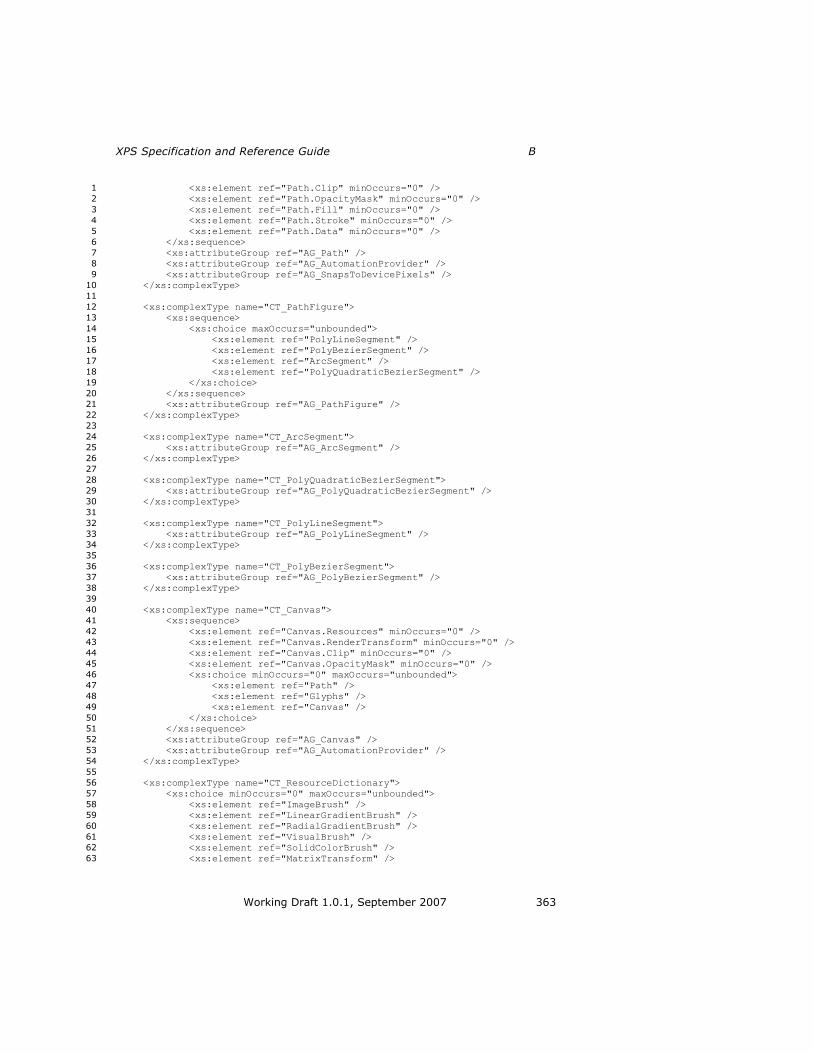
XPS Specification and Reference Guide B
Working Draft 1.0.1, September 2007 363
<xs:element ref="Path.Clip" minOccurs="0" /> 1
<xs:element ref="Path.OpacityMask" minOccurs="0" /> 2
<xs:element ref="Path.Fill" minOccurs="0" /> 3
<xs:element ref="Path.Stroke" minOccurs="0" /> 4
<xs:element ref="Path.Data" minOccurs="0" /> 5
</xs:sequence> 6
<xs:attributeGroup ref="AG_Path" /> 7
<xs:attributeGroup ref="AG_AutomationProvider" /> 8
<xs:attributeGroup ref="AG_SnapsToDevicePixels" /> 9
</xs:complexType> 10
11
<xs:complexType name="CT_PathFigure"> 12
<xs:sequence> 13
<xs:choice maxOccurs="unbounded"> 14
<xs:element ref="PolyLineSegment" /> 15
<xs:element ref="PolyBezierSegment" /> 16
<xs:element ref="ArcSegment" /> 17
<xs:element ref="PolyQuadraticBezierSegment" /> 18
</xs:choice> 19
</xs:sequence> 20
<xs:attributeGroup ref="AG_PathFigure" /> 21
</xs:complexType> 22
23
<xs:complexType name="CT_ArcSegment"> 24
<xs:attributeGroup ref="AG_ArcSegment" /> 25
</xs:complexType> 26
27
<xs:complexType name="CT_PolyQuadraticBezierSegment"> 28
<xs:attributeGroup ref="AG_PolyQuadraticBezierSegment" /> 29
</xs:complexType> 30
31
<xs:complexType name="CT_PolyLineSegment"> 32
<xs:attributeGroup ref="AG_PolyLineSegment" /> 33
</xs:complexType> 34
35
<xs:complexType name="CT_PolyBezierSegment"> 36
<xs:attributeGroup ref="AG_PolyBezierSegment" /> 37
</xs:complexType> 38
39
<xs:complexType name="CT_Canvas"> 40
<xs:sequence> 41
<xs:element ref="Canvas.Resources" minOccurs="0" /> 42
<xs:element ref="Canvas.RenderTransform" minOccurs="0" /> 43
<xs:element ref="Canvas.Clip" minOccurs="0" /> 44
<xs:element ref="Canvas.OpacityMask" minOccurs="0" /> 45
<xs:choice minOccurs="0" maxOccurs="unbounded"> 46
<xs:element ref="Path" /> 47
<xs:element ref="Glyphs" /> 48
<xs:element ref="Canvas" /> 49
</xs:choice> 50
</xs:sequence> 51
<xs:attributeGroup ref="AG_Canvas" /> 52
<xs:attributeGroup ref="AG_AutomationProvider" /> 53
</xs:complexType> 54
55
<xs:complexType name="CT_ResourceDictionary"> 56
<xs:choice minOccurs="0" maxOccurs="unbounded"> 57
<xs:element ref="ImageBrush" /> 58
<xs:element ref="LinearGradientBrush" /> 59
<xs:element ref="RadialGradientBrush" /> 60
<xs:element ref="VisualBrush" /> 61
<xs:element ref="SolidColorBrush" /> 62
<xs:element ref="MatrixTransform" /> 63

B XPS Document Schema
364 Working Draft 1.0.1, September 2007
<xs:element ref="PathGeometry" /> 1
<xs:element ref="Path" /> 2
<xs:element ref="Glyphs" /> 3
<xs:element ref="Canvas" /> 4
</xs:choice> 5
<xs:attributeGroup ref="AG_ResourceDictionary" /> 6
</xs:complexType> 7
8
<xs:complexType name="CT_FixedPage"> 9
<xs:sequence> 10
<xs:element ref="FixedPage.Resources" minOccurs="0" /> 11
<xs:choice minOccurs="0" maxOccurs="unbounded"> 12
<xs:element ref="Path" /> 13
<xs:element ref="Glyphs" /> 14
<xs:element ref="Canvas" /> 15
</xs:choice> 16
</xs:sequence> 17
<xs:attributeGroup ref="AG_FixedPage" /> 18
</xs:complexType> 19
20
<xs:complexType name="CT_FixedDocument"> 21
<xs:sequence> 22
<xs:element ref="PageContent" maxOccurs="unbounded" /> 23
</xs:sequence> 24
</xs:complexType> 25
26
<xs:complexType name="CT_PageContent"> 27
<xs:sequence> 28
<xs:element ref="PageContent.LinkTargets" minOccurs="0" /> 29
</xs:sequence> 30
<xs:attributeGroup ref="AG_PageContent" /> 31
</xs:complexType> 32
33
<xs:complexType name="CT_FixedDocumentSequence"> 34
<xs:sequence> 35
<xs:element ref="DocumentReference" maxOccurs="unbounded" /> 36
</xs:sequence> 37
</xs:complexType> 38
39
<xs:complexType name="CT_DocumentReference"> 40
<xs:attributeGroup ref="AG_DocumentReference" /> 41
</xs:complexType> 42
43
<xs:complexType name="CT_LinkTarget"> 44
<xs:attributeGroup ref="AG_LinkTarget" /> 45
</xs:complexType> 46
47
<xs:complexType name="CT_CP_LinkTargets"> 48
<xs:sequence> 49
<xs:element ref="LinkTarget" maxOccurs="unbounded" /> 50
</xs:sequence> 51
</xs:complexType> 52
53
<xs:complexType name="CT_CP_Transform"> 54
<xs:sequence> 55
<xs:element ref="MatrixTransform" /> 56
</xs:sequence> 57
</xs:complexType> 58
59
<xs:complexType name="CT_CP_Visual"> 60
<xs:choice> 61
<xs:element ref="Path" /> 62

XPS Specification and Reference Guide B
Working Draft 1.0.1, September 2007 365
<xs:element ref="Glyphs" /> 1
<xs:element ref="Canvas" /> 2
</xs:choice> 3
</xs:complexType> 4
5
<xs:complexType name="CT_CP_GradientStops"> 6
<xs:sequence> 7
<xs:element ref="GradientStop" minOccurs="2" maxOccurs="unbounded" 8
/> 9
</xs:sequence> 10
</xs:complexType> 11
12
<xs:complexType name="CT_CP_Geometry"> 13
<xs:sequence> 14
<xs:element ref="PathGeometry" /> 15
</xs:sequence> 16
</xs:complexType> 17
18
<xs:complexType name="CT_CP_Brush"> 19
<xs:choice> 20
<xs:element ref="ImageBrush" /> 21
<xs:element ref="LinearGradientBrush" /> 22
<xs:element ref="RadialGradientBrush" /> 23
<xs:element ref="SolidColorBrush" /> 24
<xs:element ref="VisualBrush" /> 25
</xs:choice> 26
</xs:complexType> 27
28
<xs:complexType name="CT_CP_Resources"> 29
<xs:sequence minOccurs="0"> 30
<xs:element ref="ResourceDictionary" /> 31
</xs:sequence> 32
</xs:complexType> 33
34
<!-- Root elements --> 35
<xs:element name="MatrixTransform" type="CT_MatrixTransform"> 36
</xs:element> 37
38
<xs:element name="SolidColorBrush" type="CT_SolidColorBrush"> 39
</xs:element> 40
41
<xs:element name="ImageBrush" type="CT_ImageBrush"> 42
</xs:element> 43
44
<xs:element name="VisualBrush" type="CT_VisualBrush"> 45
</xs:element> 46
47
<xs:element name="LinearGradientBrush" type="CT_LinearGradientBrush"> 48
</xs:element> 49
50
<xs:element name="RadialGradientBrush" type="CT_RadialGradientBrush"> 51
</xs:element> 52
53
<xs:element name="Glyphs" type="CT_Glyphs"> 54
</xs:element> 55
56
<xs:element name="Path" type="CT_Path"> 57
</xs:element> 58
59
<xs:element name="Canvas" type="CT_Canvas"> 60
</xs:element> 61
62
<xs:element name="GradientStop" type="CT_GradientStop"> 63

B XPS Document Schema
366 Working Draft 1.0.1, September 2007
</xs:element> 1
2
<xs:element name="ResourceDictionary" type="CT_ResourceDictionary"> 3
</xs:element> 4
5
<xs:element name="PathGeometry" type="CT_PathGeometry"> 6
</xs:element> 7
8
<xs:element name="PathFigure" type="CT_PathFigure"> 9
</xs:element> 10
11
<xs:element name="PolyLineSegment" type="CT_PolyLineSegment"> 12
</xs:element> 13
14
<xs:element name="ArcSegment" type="CT_ArcSegment"> 15
</xs:element> 16
17
<xs:element name="PolyBezierSegment" type="CT_PolyBezierSegment"> 18
</xs:element> 19
20
<xs:element name="PolyQuadraticBezierSegment" 21
type="CT_PolyQuadraticBezierSegment"> 22
</xs:element> 23
24
<xs:element name="FixedPage" type="CT_FixedPage"> 25
</xs:element> 26
27
<xs:element name="FixedDocument" type="CT_FixedDocument"> 28
</xs:element> 29
30
<xs:element name="PageContent" type="CT_PageContent"> 31
</xs:element> 32
33
<xs:element name="FixedDocumentSequence" type="CT_FixedDocumentSequence"> 34
</xs:element> 35
36
<xs:element name="DocumentReference" type="CT_DocumentReference"> 37
</xs:element> 38
39
<xs:element name="LinkTarget" type="CT_LinkTarget"> 40
</xs:element> 41
42
<xs:element name="PageContent.LinkTargets" type="CT_CP_LinkTargets"> 43
</xs:element> 44
45
<xs:element name="ImageBrush.Transform" type="CT_CP_Transform"> 46
</xs:element> 47
48
<xs:element name="VisualBrush.Transform" type="CT_CP_Transform"> 49
</xs:element> 50
51
<xs:element name="LinearGradientBrush.Transform" type="CT_CP_Transform"> 52
</xs:element> 53
54
<xs:element name="RadialGradientBrush.Transform" type="CT_CP_Transform"> 55
</xs:element> 56
57
<xs:element name="PathGeometry.Transform" type="CT_CP_Transform"> 58
</xs:element> 59
60
<xs:element name="Glyphs.RenderTransform" type="CT_CP_Transform"> 61
</xs:element> 62

XPS Specification and Reference Guide B
Working Draft 1.0.1, September 2007 367
1
<xs:element name="Path.RenderTransform" type="CT_CP_Transform"> 2
</xs:element> 3
4
<xs:element name="Canvas.RenderTransform" type="CT_CP_Transform"> 5
</xs:element> 6
7
<xs:element name="VisualBrush.Visual" type="CT_CP_Visual"> 8
</xs:element> 9
10
<xs:element name="LinearGradientBrush.GradientStops" 11
type="CT_CP_GradientStops"> 12
</xs:element> 13
14
<xs:element name="RadialGradientBrush.GradientStops" 15
type="CT_CP_GradientStops"> 16
</xs:element> 17
18
<xs:element name="Glyphs.Clip" type="CT_CP_Geometry"> 19
</xs:element> 20
21
<xs:element name="Path.Clip" type="CT_CP_Geometry"> 22
</xs:element> 23
24
<xs:element name="Canvas.Clip" type="CT_CP_Geometry"> 25
</xs:element> 26
27
<xs:element name="Glyphs.OpacityMask" type="CT_CP_Brush"> 28
</xs:element> 29
30
<xs:element name="Path.OpacityMask" type="CT_CP_Brush"> 31
</xs:element> 32
33
<xs:element name="Canvas.OpacityMask" type="CT_CP_Brush"> 34
</xs:element> 35
36
<xs:element name="Glyphs.Fill" type="CT_CP_Brush"> 37
</xs:element> 38
39
<xs:element name="Path.Fill" type="CT_CP_Brush"> 40
</xs:element> 41
42
<xs:element name="Path.Data" type="CT_CP_Geometry"> 43
</xs:element> 44
45
<xs:element name="Path.Stroke" type="CT_CP_Brush"> 46
</xs:element> 47
48
<xs:element name="Canvas.Resources" type="CT_CP_Resources"> 49
</xs:element> 50
51
<xs:element name="FixedPage.Resources" type="CT_CP_Resources"> 52
</xs:element> 53
54
<xs:attributeGroup name="AG_GradientStop"> 55
<xs:attribute name="Color" type="ST_Color" use="required"> 56
</xs:attribute> 57
<xs:attribute name="Offset" type="ST_Double" use="required"> 58
</xs:attribute> 59
</xs:attributeGroup> 60
61
<xs:attributeGroup name="AG_Brush"> 62
<xs:attribute name="Opacity" type="ST_ZeroOne" default="1.0"> 63
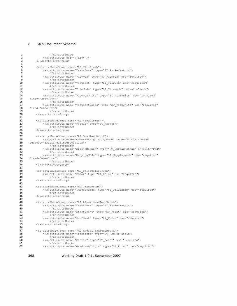
B XPS Document Schema
368 Working Draft 1.0.1, September 2007
</xs:attribute> 1
<xs:attribute ref="x:Key" /> 2
</xs:attributeGroup> 3
4
<xs:attributeGroup name="AG_TileBrush"> 5
<xs:attribute name="Transform" type="ST_RscRefMatrix"> 6
</xs:attribute> 7
<xs:attribute name="Viewbox" type="ST_ViewBox" use="required"> 8
</xs:attribute> 9
<xs:attribute name="Viewport" type="ST_ViewBox" use="required"> 10
</xs:attribute> 11
<xs:attribute name="TileMode" type="ST_TileMode" default="None"> 12
</xs:attribute> 13
<xs:attribute name="ViewboxUnits" type="ST_ViewUnits" use="required" 14
fixed="Absolute"> 15
</xs:attribute> 16
<xs:attribute name="ViewportUnits" type="ST_ViewUnits" use="required" 17
fixed="Absolute"> 18
</xs:attribute> 19
</xs:attributeGroup> 20
21
<xs:attributeGroup name="AG_VisualBrush"> 22
<xs:attribute name="Visual" type="ST_RscRef"> 23
</xs:attribute> 24
</xs:attributeGroup> 25
26
<xs:attributeGroup name="AG_GradientBrush"> 27
<xs:attribute name="ColorInterpolationMode" type="ST_ClrIntMode" 28
default="SRgbLinearInterpolation"> 29
</xs:attribute> 30
<xs:attribute name="SpreadMethod" type="ST_SpreadMethod" default="Pad"> 31
</xs:attribute> 32
<xs:attribute name="MappingMode" type="ST_MappingMode" use="required" 33
fixed="Absolute"> 34
</xs:attribute> 35
</xs:attributeGroup> 36
37
<xs:attributeGroup name="AG_SolidColorBrush"> 38
<xs:attribute name="Color" type="ST_Color" use="required"> 39
</xs:attribute> 40
</xs:attributeGroup> 41
42
<xs:attributeGroup name="AG_ImageBrush"> 43
<xs:attribute name="ImageSource" type="ST_UriCtxBmp" use="required"> 44
</xs:attribute> 45
</xs:attributeGroup> 46
47
<xs:attributeGroup name="AG_LinearGradientBrush"> 48
<xs:attribute name="Transform" type="ST_RscRefMatrix"> 49
</xs:attribute> 50
<xs:attribute name="StartPoint" type="ST_Point" use="required"> 51
</xs:attribute> 52
<xs:attribute name="EndPoint" type="ST_Point" use="required"> 53
</xs:attribute> 54
</xs:attributeGroup> 55
56
<xs:attributeGroup name="AG_RadialGradientBrush"> 57
<xs:attribute name="Transform" type="ST_RscRefMatrix"> 58
</xs:attribute> 59
<xs:attribute name="Center" type="ST_Point" use="required"> 60
</xs:attribute> 61
<xs:attribute name="GradientOrigin" type="ST_Point" use="required"> 62

XPS Specification and Reference Guide B
Working Draft 1.0.1, September 2007 369
</xs:attribute> 1
<xs:attribute name="RadiusX" type="ST_GEZero" use="required"> 2
</xs:attribute> 3
<xs:attribute name="RadiusY" type="ST_GEZero" use="required"> 4
</xs:attribute> 5
</xs:attributeGroup> 6
7
<xs:attributeGroup name="AG_PathGeometry"> 8
<xs:attribute name="Figures" type="ST_AbbrGeom"> 9
</xs:attribute> 10
<xs:attribute name="FillRule" type="ST_FillRule" default="EvenOdd"> 11
</xs:attribute> 12
<xs:attribute name="Transform" type="ST_RscRefMatrix"> 13
</xs:attribute> 14
<xs:attribute ref="x:Key" /> 15
</xs:attributeGroup> 16
17
<xs:attributeGroup name="AG_ResourceDictionary"> 18
<xs:attribute name="Source" type="xs:anyURI"> 19
</xs:attribute> 20
</xs:attributeGroup> 21
22
<xs:attributeGroup name="AG_PolyLineSegment"> 23
<xs:attribute name="Points" type="ST_Points" use="required"> 24
</xs:attribute> 25
<xs:attribute name="IsStroked" type="ST_Boolean" default="true"> 26
</xs:attribute> 27
</xs:attributeGroup> 28
29
<xs:attributeGroup name="AG_ArcSegment"> 30
<xs:attribute name="Point" type="ST_Point" use="required"> 31
</xs:attribute> 32
<xs:attribute name="Size" type="ST_PointGE0" use="required"> 33
</xs:attribute> 34
<xs:attribute name="RotationAngle" type="ST_Double" use="required"> 35
</xs:attribute> 36
<xs:attribute name="IsLargeArc" type="ST_Boolean" use="required"> 37
</xs:attribute> 38
<xs:attribute name="SweepDirection" type="ST_SweepDirection" 39
use="required"> 40
</xs:attribute> 41
<xs:attribute name="IsStroked" type="ST_Boolean" default="true"> 42
</xs:attribute> 43
</xs:attributeGroup> 44
45
<xs:attributeGroup name="AG_PolyBezierSegment"> 46
<xs:attribute name="Points" type="ST_Points" use="required"> 47
</xs:attribute> 48
<xs:attribute name="IsStroked" type="ST_Boolean" default="true"> 49
</xs:attribute> 50
</xs:attributeGroup> 51
52
<xs:attributeGroup name="AG_PolyQuadraticBezierSegment"> 53
<xs:attribute name="Points" type="ST_Points" use="required"> 54
</xs:attribute> 55
<xs:attribute name="IsStroked" type="ST_Boolean" default="true"> 56
</xs:attribute> 57
</xs:attributeGroup> 58
59
<xs:attributeGroup name="AG_Glyphs"> 60
<xs:attribute name="BidiLevel" default="0"> 61
<xs:simpleType> 62
<xs:restriction base="xs:integer"> 63

B XPS Document Schema
370 Working Draft 1.0.1, September 2007
<xs:minInclusive value="0" /> 1
<xs:maxInclusive value="61" /> 2
</xs:restriction> 3
</xs:simpleType> 4
</xs:attribute> 5
<xs:attribute name="CaretStops" type="ST_CaretStops"> 6
</xs:attribute> 7
<xs:attribute name="DeviceFontName" type="ST_UnicodeString"> 8
</xs:attribute> 9
<xs:attribute name="Fill" type="ST_RscRefColor"> 10
</xs:attribute> 11
<xs:attribute name="FontRenderingEmSize" type="ST_GEZero" 12
use="required"> 13
</xs:attribute> 14
<xs:attribute name="FontUri" type="xs:anyURI" use="required"> 15
</xs:attribute> 16
<xs:attribute name="OriginX" type="ST_Double" use="required"> 17
</xs:attribute> 18
<xs:attribute name="OriginY" type="ST_Double" use="required"> 19
</xs:attribute> 20
<xs:attribute name="IsSideways" type="ST_Boolean" default="false"> 21
</xs:attribute> 22
<xs:attribute name="Indices" type="ST_Indices"> 23
</xs:attribute> 24
<xs:attribute name="UnicodeString" type="ST_UnicodeString"> 25
</xs:attribute> 26
<xs:attribute name="StyleSimulations" type="ST_StyleSimulations" 27
default="None"> 28
</xs:attribute> 29
<xs:attribute name="RenderTransform" type="ST_RscRefMatrix"> 30
</xs:attribute> 31
<xs:attribute name="Clip" type="ST_RscRefAbbrGeomF"> 32
</xs:attribute> 33
<xs:attribute name="Opacity" type="ST_ZeroOne" default="1.0"> 34
</xs:attribute> 35
<xs:attribute name="OpacityMask" type="ST_RscRef"> 36
</xs:attribute> 37
<xs:attribute name="Name" type="ST_Name"> 38
</xs:attribute> 39
<xs:attribute name="FixedPage.NavigateUri" type="xs:anyURI"> 40
</xs:attribute> 41
<xs:attribute ref="xml:lang"> 42
</xs:attribute> 43
<xs:attribute ref="x:Key" /> 44
</xs:attributeGroup> 45
46
<xs:attributeGroup name="AG_Path"> 47
<xs:attribute name="Data" type="ST_RscRefAbbrGeomF"> 48
</xs:attribute> 49
<xs:attribute name="Fill" type="ST_RscRefColor"> 50
</xs:attribute> 51
<xs:attribute name="RenderTransform" type="ST_RscRefMatrix"> 52
</xs:attribute> 53
<xs:attribute name="Clip" type="ST_RscRefAbbrGeomF"> 54
</xs:attribute> 55
<xs:attribute name="Opacity" type="ST_ZeroOne" default="1.0"> 56
</xs:attribute> 57
<xs:attribute name="OpacityMask" type="ST_RscRef"> 58
</xs:attribute> 59
<xs:attribute name="Stroke" type="ST_RscRefColor"> 60
</xs:attribute> 61
<xs:attribute name="StrokeDashArray" type="ST_EvenArrayPos"> 62

XPS Specification and Reference Guide B
Working Draft 1.0.1, September 2007 371
</xs:attribute> 1
<xs:attribute name="StrokeDashCap" type="ST_DashCap" default="Flat"> 2
</xs:attribute> 3
<xs:attribute name="StrokeDashOffset" type="ST_Double" default="0.0"> 4
</xs:attribute> 5
<xs:attribute name="StrokeEndLineCap" type="ST_LineCap" default="Flat"> 6
</xs:attribute> 7
<xs:attribute name="StrokeStartLineCap" type="ST_LineCap" 8
default="Flat"> 9
</xs:attribute> 10
<xs:attribute name="StrokeLineJoin" type="ST_LineJoin" default="Miter"> 11
</xs:attribute> 12
<xs:attribute name="StrokeMiterLimit" type="ST_GEOne" default="10.0"> 13
</xs:attribute> 14
<xs:attribute name="StrokeThickness" type="ST_GEZero" default="1.0"> 15
</xs:attribute> 16
<xs:attribute name="Name" type="ST_Name"> 17
</xs:attribute> 18
<xs:attribute name="FixedPage.NavigateUri" type="xs:anyURI"> 19
</xs:attribute> 20
<xs:attribute ref="xml:lang"> 21
</xs:attribute> 22
<xs:attribute ref="x:Key" /> 23
</xs:attributeGroup> 24
25
<xs:attributeGroup name="AG_PathFigure"> 26
<xs:attribute name="IsClosed" type="ST_Boolean" default="false"> 27
</xs:attribute> 28
<xs:attribute name="StartPoint" type="ST_Point" use="required"> 29
</xs:attribute> 30
<xs:attribute name="IsFilled" type="ST_Boolean" default="true"> 31
</xs:attribute> 32
</xs:attributeGroup> 33
34
<xs:attributeGroup name="AG_Canvas"> 35
<xs:attribute name="RenderTransform" type="ST_RscRefMatrix"> 36
</xs:attribute> 37
<xs:attribute name="Clip" type="ST_RscRefAbbrGeomF"> 38
</xs:attribute> 39
<xs:attribute name="Opacity" type="ST_ZeroOne" default="1.0"> 40
</xs:attribute> 41
<xs:attribute name="OpacityMask" type="ST_RscRef"> 42
</xs:attribute> 43
<xs:attribute name="Name" type="ST_Name"> 44
</xs:attribute> 45
<xs:attribute name="RenderOptions.EdgeMode" type="ST_EdgeMode"> 46
</xs:attribute> 47
<xs:attribute name="FixedPage.NavigateUri" type="xs:anyURI"> 48
</xs:attribute> 49
<xs:attribute ref="xml:lang"> 50
</xs:attribute> 51
<xs:attribute ref="x:Key" /> 52
</xs:attributeGroup> 53
54
<xs:attributeGroup name="AG_PageContent"> 55
<xs:attribute name="Source" type="xs:anyURI" use="required"> 56
</xs:attribute> 57
<xs:attribute name="Width" type="ST_GEOne"> 58
</xs:attribute> 59
<xs:attribute name="Height" type="ST_GEOne"> 60
</xs:attribute> 61
</xs:attributeGroup> 62
63
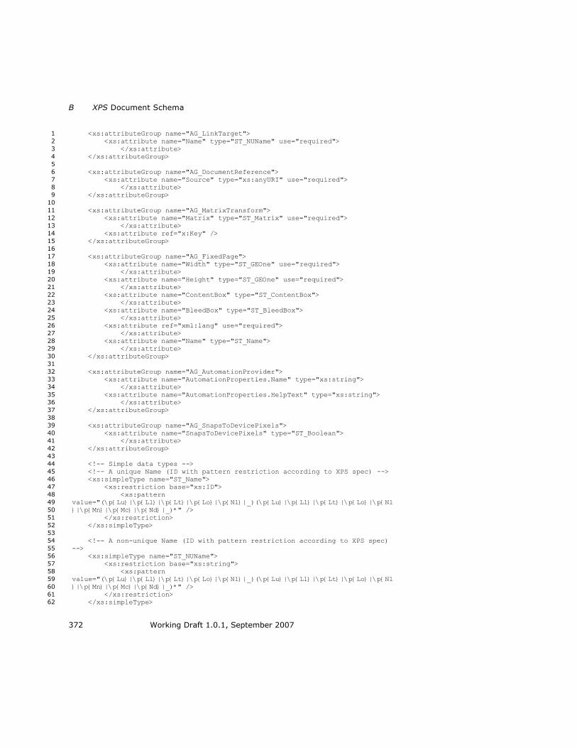
B XPS Document Schema
372 Working Draft 1.0.1, September 2007
<xs:attributeGroup name="AG_LinkTarget"> 1
<xs:attribute name="Name" type="ST_NUName" use="required"> 2
</xs:attribute> 3
</xs:attributeGroup> 4
5
<xs:attributeGroup name="AG_DocumentReference"> 6
<xs:attribute name="Source" type="xs:anyURI" use="required"> 7
</xs:attribute> 8
</xs:attributeGroup> 9
10
<xs:attributeGroup name="AG_MatrixTransform"> 11
<xs:attribute name="Matrix" type="ST_Matrix" use="required"> 12
</xs:attribute> 13
<xs:attribute ref="x:Key" /> 14
</xs:attributeGroup> 15
16
<xs:attributeGroup name="AG_FixedPage"> 17
<xs:attribute name="Width" type="ST_GEOne" use="required"> 18
</xs:attribute> 19
<xs:attribute name="Height" type="ST_GEOne" use="required"> 20
</xs:attribute> 21
<xs:attribute name="ContentBox" type="ST_ContentBox"> 22
</xs:attribute> 23
<xs:attribute name="BleedBox" type="ST_BleedBox"> 24
</xs:attribute> 25
<xs:attribute ref="xml:lang" use="required"> 26
</xs:attribute> 27
<xs:attribute name="Name" type="ST_Name"> 28
</xs:attribute> 29
</xs:attributeGroup> 30
31
<xs:attributeGroup name="AG_AutomationProvider"> 32
<xs:attribute name="AutomationProperties.Name" type="xs:string"> 33
</xs:attribute> 34
<xs:attribute name="AutomationProperties.HelpText" type="xs:string"> 35
</xs:attribute> 36
</xs:attributeGroup> 37
38
<xs:attributeGroup name="AG_SnapsToDevicePixels"> 39
<xs:attribute name="SnapsToDevicePixels" type="ST_Boolean"> 40
</xs:attribute> 41
</xs:attributeGroup> 42
43
<!-- Simple data types --> 44
<!-- A unique Name (ID with pattern restriction according to XPS spec) --> 45
<xs:simpleType name="ST_Name"> 46
<xs:restriction base="xs:ID"> 47
<xs:pattern 48
value="(\p{Lu}|\p{Ll}|\p{Lt}|\p{Lo}|\p{Nl}|_)(\p{Lu}|\p{Ll}|\p{Lt}|\p{Lo}|\p{Nl49
}|\p{Mn}|\p{Mc}|\p{Nd}|_)*" /> 50
</xs:restriction> 51
</xs:simpleType> 52
53
<!-- A non-unique Name (ID with pattern restriction according to XPS spec) 54
--> 55
<xs:simpleType name="ST_NUName"> 56
<xs:restriction base="xs:string"> 57
<xs:pattern 58
value="(\p{Lu}|\p{Ll}|\p{Lt}|\p{Lo}|\p{Nl}|_)(\p{Lu}|\p{Ll}|\p{Lt}|\p{Lo}|\p{Nl59
}|\p{Mn}|\p{Mc}|\p{Nd}|_)*" /> 60
</xs:restriction> 61
</xs:simpleType> 62

XPS Specification and Reference Guide B
Working Draft 1.0.1, September 2007 373
1
<!-- Boolean with true and false only (no 0 or 1) --> 2
<xs:simpleType name="ST_Boolean"> 3
<xs:restriction base="xs:boolean"> 4
<xs:pattern value="true|false" /> 5
</xs:restriction> 6
</xs:simpleType> 7
8
<!-- real number from 0.0 to 1.0 inclusive --> 9
<xs:simpleType name="ST_ZeroOne"> 10
<xs:restriction base="ST_Double"> 11
<xs:minInclusive value="0.0" /> 12
<xs:maxInclusive value="1.0" /> 13
</xs:restriction> 14
</xs:simpleType> 15
16
<!-- positive real number --> 17
<xs:simpleType name="ST_GEZero"> 18
<xs:restriction base="ST_Double"> 19
<xs:minInclusive value="0.0" /> 20
</xs:restriction> 21
</xs:simpleType> 22
23
<!-- positive real number, equal or greater than one --> 24
<xs:simpleType name="ST_GEOne"> 25
<xs:restriction base="ST_Double"> 26
<xs:minInclusive value="1.0" /> 27
</xs:restriction> 28
</xs:simpleType> 29
30
<!-- Double --> 31
<xs:simpleType name="ST_Double"> 32
<xs:restriction base="xs:double"> 33
<xs:whiteSpace value="collapse" /> 34
<!-- 35
<xs:pattern value="[rn]"/> 36
--> 37
<xs:pattern value="((\-|\+)?(([0-9]+(\.[0-9]+)?)|(\.[0-38
9]+))((e|E)(\-|\+)?[0-9]+)?)" /> 39
</xs:restriction> 40
</xs:simpleType> 41
42
<!-- Point: 2 numbers, separated by , and arbitrary whitespace --> 43
<xs:simpleType name="ST_Point"> 44
<xs:restriction base="xs:string"> 45
<xs:whiteSpace value="collapse" /> 46
<!-- 47
<xs:pattern value="[rn][scs][rn]"/> 48
--> 49
<xs:pattern value="((\-|\+)?(([0-9]+(\.[0-9]+)?)|(\.[0-50
9]+))((e|E)(\-|\+)?[0-9]+)?)( ?, ?)((\-|\+)?(([0-9]+(\.[0-9]+)?)|(\.[0-51
9]+))((e|E)(\-|\+)?[0-9]+)?)" /> 52
</xs:restriction> 53
</xs:simpleType> 54
55
<!-- PointGE0: 2 non-negative numbers, separated by , and arbitrary 56
whitespace --> 57
<xs:simpleType name="ST_PointGE0"> 58
<xs:restriction base="xs:string"> 59
<xs:whiteSpace value="collapse" /> 60
<!-- 61
<xs:pattern value="[prn][scs][prn]"/> 62
--> 63

B XPS Document Schema
374 Working Draft 1.0.1, September 2007
<xs:pattern value="(\+?(([0-9]+(\.[0-9]+)?)|(\.[0-9]+))((e|E)(\-1
|\+)?[0-9]+)?)( ?, ?)(\+?(([0-9]+(\.[0-9]+)?)|(\.[0-9]+))((e|E)(\-|\+)?[0-2
9]+)?)" /> 3
</xs:restriction> 4
</xs:simpleType> 5
6
<!-- Points: List of ST_Point, separated by arbitrary whitespace --> 7
<xs:simpleType name="ST_Points"> 8
<xs:restriction base="xs:string"> 9
<xs:whiteSpace value="collapse" /> 10
<!-- 11
<xs:pattern value="[rn][scs][rn]( [rn][scs][rn])*"/> 12
--> 13
<xs:pattern value="((\-|\+)?(([0-9]+(\.[0-9]+)?)|(\.[0-14
9]+))((e|E)(\-|\+)?[0-9]+)?)( ?, ?)((\-|\+)?(([0-9]+(\.[0-9]+)?)|(\.[0-15
9]+))((e|E)(\-|\+)?[0-9]+)?)( ((\-|\+)?(([0-9]+(\.[0-9]+)?)|(\.[0-16
9]+))((e|E)(\-|\+)?[0-9]+)?)( ?, ?)((\-|\+)?(([0-9]+(\.[0-9]+)?)|(\.[0-17
9]+))((e|E)(\-|\+)?[0-9]+)?))*" /> 18
</xs:restriction> 19
</xs:simpleType> 20
21
<!-- EvenArray: List with even number of entries of non-negative numbers. 22
--> 23
<xs:simpleType name="ST_EvenArrayPos"> 24
<xs:restriction base="xs:string"> 25
<xs:whiteSpace value="collapse" /> 26
<!-- 27
<xs:pattern value="[prn] [prn]( [prn] [prn])*"/> 28
--> 29
<xs:pattern value="(\+?(([0-9]+(\.[0-9]+)?)|(\.[0-9]+))((e|E)(\-30
|\+)?[0-9]+)?) (\+?(([0-9]+(\.[0-9]+)?)|(\.[0-9]+))((e|E)(\-|\+)?[0-9]+)?)( 31
(\+?(([0-9]+(\.[0-9]+)?)|(\.[0-9]+))((e|E)(\-|\+)?[0-9]+)?) (\+?(([0-9]+(\.[0-32
9]+)?)|(\.[0-9]+))((e|E)(\-|\+)?[0-9]+)?))*" /> 33
</xs:restriction> 34
</xs:simpleType> 35
36
<!-- Array: List of numbers. --> 37
<xs:simpleType name="ST_Array"> 38
<xs:restriction base="xs:string"> 39
<xs:whiteSpace value="collapse" /> 40
<!-- 41
<xs:pattern value="([rn] ?)*"/> 42
--> 43
<xs:pattern value="(((\-|\+)?(([0-9]+(\.[0-9]+)?)|(\.[0-44
9]+))((e|E)(\-|\+)?[0-9]+)?) ?)*" /> 45
</xs:restriction> 46
</xs:simpleType> 47
48
<!-- ViewBox: 4 numbers, separated by , and arbitrary whitespace. Second 49
number pair must be non-negative --> 50
<xs:simpleType name="ST_ViewBox"> 51
<xs:restriction base="xs:string"> 52
<xs:whiteSpace value="collapse" /> 53
<!-- 54
<xs:pattern value="[rn][scs][rn][scs][prn][scs][prn]"/> 55
--> 56
<xs:pattern value="((\-|\+)?(([0-9]+(\.[0-9]+)?)|(\.[0-57
9]+))((e|E)(\-|\+)?[0-9]+)?)( ?, ?)((\-|\+)?(([0-9]+(\.[0-9]+)?)|(\.[0-58
9]+))((e|E)(\-|\+)?[0-9]+)?)( ?, ?)(\+?(([0-9]+(\.[0-9]+)?)|(\.[0-59
9]+))((e|E)(\-|\+)?[0-9]+)?)( ?, ?)(\+?(([0-9]+(\.[0-9]+)?)|(\.[0-60
9]+))((e|E)(\-|\+)?[0-9]+)?)" /> 61
</xs:restriction> 62

XPS Specification and Reference Guide B
Working Draft 1.0.1, September 2007 375
</xs:simpleType> 1
2
<!-- ContentBox: 4 non-negative numbers, separated by commas and arbitrary 3
whitespace --> 4
<xs:simpleType name="ST_ContentBox"> 5
<xs:restriction base="xs:string"> 6
<xs:whiteSpace value="collapse" /> 7
<!-- 8
<xs:pattern value="[prn][scs][prn][scs][prn][scs][prn]"/> 9
--> 10
<xs:pattern value="(\+?(([0-9]+(\.[0-9]+)?)|(\.[0-9]+))((e|E)(\-11
|\+)?[0-9]+)?)( ?, ?)(\+?(([0-9]+(\.[0-9]+)?)|(\.[0-9]+))((e|E)(\-|\+)?[0-12
9]+)?)( ?, ?)(\+?(([0-9]+(\.[0-9]+)?)|(\.[0-9]+))((e|E)(\-|\+)?[0-9]+)?)( ?, 13
?)(\+?(([0-9]+(\.[0-9]+)?)|(\.[0-9]+))((e|E)(\-|\+)?[0-9]+)?)" /> 14
</xs:restriction> 15
</xs:simpleType> 16
17
<!-- BleedBox: 4 numbers, separated by , and arbitrary whitespace. Second 18
number pair must be non-negative --> 19
<xs:simpleType name="ST_BleedBox"> 20
<xs:restriction base="xs:string"> 21
<xs:whiteSpace value="collapse" /> 22
<!-- 23
<xs:pattern value="[rn][scs][rn][scs][prn][scs][prn]"/> 24
--> 25
<xs:pattern value="((\-|\+)?(([0-9]+(\.[0-9]+)?)|(\.[0-26
9]+))((e|E)(\-|\+)?[0-9]+)?)( ?, ?)((\-|\+)?(([0-9]+(\.[0-9]+)?)|(\.[0-27
9]+))((e|E)(\-|\+)?[0-9]+)?)( ?, ?)(\+?(([0-9]+(\.[0-9]+)?)|(\.[0-28
9]+))((e|E)(\-|\+)?[0-9]+)?)( ?, ?)(\+?(([0-9]+(\.[0-9]+)?)|(\.[0-29
9]+))((e|E)(\-|\+)?[0-9]+)?)" /> 30
</xs:restriction> 31
</xs:simpleType> 32
33
<!-- Bare Matrix form: 6 numbers separated by , and arbitrary whitespace --34
> 35
<xs:simpleType name="ST_Matrix"> 36
<xs:restriction base="xs:string"> 37
<xs:whiteSpace value="collapse" /> 38
<!-- 39
<xs:pattern 40
value="[rn][scs][rn][scs][rn][scs][rn][scs][rn][scs][rn]"/> 41
--> 42
<xs:pattern value="((\-|\+)?(([0-9]+(\.[0-9]+)?)|(\.[0-43
9]+))((e|E)(\-|\+)?[0-9]+)?)( ?, ?)((\-|\+)?(([0-9]+(\.[0-9]+)?)|(\.[0-44
9]+))((e|E)(\-|\+)?[0-9]+)?)( ?, ?)((\-|\+)?(([0-9]+(\.[0-9]+)?)|(\.[0-45
9]+))((e|E)(\-|\+)?[0-9]+)?)( ?, ?)((\-|\+)?(([0-9]+(\.[0-9]+)?)|(\.[0-46
9]+))((e|E)(\-|\+)?[0-9]+)?)( ?, ?)((\-|\+)?(([0-9]+(\.[0-9]+)?)|(\.[0-47
9]+))((e|E)(\-|\+)?[0-9]+)?)( ?, ?)((\-|\+)?(([0-9]+(\.[0-9]+)?)|(\.[0-48
9]+))((e|E)(\-|\+)?[0-9]+)?)" /> 49
</xs:restriction> 50
</xs:simpleType> 51
52
<!-- Color: 6 or 8 hex digits --> 53
<xs:simpleType name="ST_Color"> 54
<xs:restriction base="xs:string"> 55
<!-- The pattern restriction does not check for scRGB gamut --> 56
<!-- The pattern restriction does not check for color profile URI 57
validity --> 58
<xs:whiteSpace value="collapse" /> 59
<!-- 60
<xs:pattern value="(#([0-9a-fA-F]{2})?[0-9a-fA-F]{6})|\ 61
(sc# ?[dec][scs][dec][scs][dec]([scs][dec])?)|\ 62

B XPS Document Schema
376 Working Draft 1.0.1, September 2007
(ContextColor +[\S]+ 1
?[dec]([scs][dec]){3,8})"/> 2
--> 3
<xs:pattern value="(#([0-9a-fA-F]{2})?[0-9a-fA-F]{6})|(sc# ?(\-4
?(([0-9]+(\.[0-9]+)?)|(\.[0-9]+)))( ?, ?)(\-?(([0-9]+(\.[0-9]+)?)|(\.[0-9]+)))( 5
?, ?)(\-?(([0-9]+(\.[0-9]+)?)|(\.[0-9]+)))(( ?, ?)(\-?(([0-9]+(\.[0-6
9]+)?)|(\.[0-9]+))))?)|(ContextColor +[\S]+ ?(\-?(([0-9]+(\.[0-9]+)?)|(\.[0-7
9]+)))(( ?, ?)(\-?(([0-9]+(\.[0-9]+)?)|(\.[0-9]+)))){3,8})" /> 8
</xs:restriction> 9
</xs:simpleType> 10
11
<!-- Indices grammar for Glyphs.CaretStops --> 12
<xs:simpleType name="ST_CaretStops"> 13
<xs:restriction base="xs:string"> 14
<xs:whiteSpace value="collapse" /> 15
<xs:pattern value="[0-9A-Fa-f]*" /> 16
</xs:restriction> 17
</xs:simpleType> 18
19
<!-- Indices grammar for Glyphs.Indices --> 20
<xs:simpleType name="ST_Indices"> 21
<xs:restriction base="xs:string"> 22
<xs:whiteSpace value="collapse" /> 23
<!-- 24
<xs:pattern value="(\ 25
((\([pint](:[pint])?\))?[uint])?\ 26
(,[prn]?(,[rn]?(,[rn])?)?)?\ 27
)\ 28
(;\ 29
((\([pint](:[pint])?\))?[uint])?\ 30
(,[prn]?(,[rn]?(,[rn])?)?)?\ 31
)*" /> 32
--> 33
<xs:pattern value="(((\(([1-9][0-9]*)(:([1-9][0-9]*))?\))?([0-34
9]+))?(,(\+?(([0-9]+(\.[0-9]+)?)|(\.[0-9]+))((e|E)(\-|\+)?[0-9]+)?)?(,((\-35
|\+)?(([0-9]+(\.[0-9]+)?)|(\.[0-9]+))((e|E)(\-|\+)?[0-9]+)?)?(,((\-|\+)?(([0-36
9]+(\.[0-9]+)?)|(\.[0-9]+))((e|E)(\-|\+)?[0-9]+)?))?)?)?)(;((\(([1-9][0-37
9]*)(:([1-9][0-9]*))?\))?([0-9]+))?(,(\+?(([0-9]+(\.[0-9]+)?)|(\.[0-38
9]+))((e|E)(\-|\+)?[0-9]+)?)?(,((\-|\+)?(([0-9]+(\.[0-9]+)?)|(\.[0-39
9]+))((e|E)(\-|\+)?[0-9]+)?)?(,((\-|\+)?(([0-9]+(\.[0-9]+)?)|(\.[0-40
9]+))((e|E)(\-|\+)?[0-9]+)?))?)?)?)*" /> 41
</xs:restriction> 42
</xs:simpleType> 43
44
<!-- UnicodeString grammar --> 45
<xs:simpleType name="ST_UnicodeString"> 46
<xs:restriction base="xs:string"> 47
<xs:pattern value="(([^\{]|(\{\})).*)?" /> 48
</xs:restriction> 49
</xs:simpleType> 50
51
<!-- Abbreviated Geometry grammar for Path.Data , clip and Geometries --> 52
<xs:simpleType name="ST_AbbrGeomF"> 53
<xs:restriction base="xs:string"> 54
<xs:whiteSpace value="collapse" /> 55
<!-- 56
<xs:pattern value="(F ?(0|1))?\ 57
( ?(M|m)( ?[rn][scs][rn]))\ 58
(\ 59
( ?(M|m)( ?[rn][scs][rn]))|\ 60
( ?(L|l)( ?[rn][scs][rn])( 61
[rn][scs][rn])*)|\ 62

XPS Specification and Reference Guide B
Working Draft 1.0.1, September 2007 377
( ?(H|h|V|v)( ?[rn])( [rn])*)|\ 1
( ?(Q|q|S|s)( ?[rn][scs][rn] 2
[rn][scs][rn])(( [rn][scs][rn]){2})*)|\ 3
( ?(C|c)( ?[rn][scs][rn]( 4
[rn][scs][rn]){2})(( [rn][scs][rn]){3})*)|\ 5
( ?(A|a)( ?[rn][scs][rn] [rn] [0-1] [0-1] 6
[rn][scs][rn])\ 7
( [rn][scs][rn] [rn] [0-1] 8
[0-1] [rn][scs][rn])*)|\ 9
( ?(Z|z))\ 10
)*"/> 11
--> 12
<xs:pattern value="(F ?(0|1))?( ?(M|m)( ?((\-|\+)?(([0-9]+(\.[0-13
9]+)?)|(\.[0-9]+))((e|E)(\-|\+)?[0-9]+)?)( ?, ?)((\-|\+)?(([0-9]+(\.[0-14
9]+)?)|(\.[0-9]+))((e|E)(\-|\+)?[0-9]+)?)))(( ?(M|m)( ?((\-|\+)?(([0-9]+(\.[0-15
9]+)?)|(\.[0-9]+))((e|E)(\-|\+)?[0-9]+)?)( ?, ?)((\-|\+)?(([0-9]+(\.[0-16
9]+)?)|(\.[0-9]+))((e|E)(\-|\+)?[0-9]+)?)))|( ?(L|l)( ?((\-|\+)?(([0-9]+(\.[0-17
9]+)?)|(\.[0-9]+))((e|E)(\-|\+)?[0-9]+)?)( ?, ?)((\-|\+)?(([0-9]+(\.[0-18
9]+)?)|(\.[0-9]+))((e|E)(\-|\+)?[0-9]+)?))( ((\-|\+)?(([0-9]+(\.[0-19
9]+)?)|(\.[0-9]+))((e|E)(\-|\+)?[0-9]+)?)( ?, ?)((\-|\+)?(([0-9]+(\.[0-20
9]+)?)|(\.[0-9]+))((e|E)(\-|\+)?[0-9]+)?))*)|( ?(H|h|V|v)( ?((\-|\+)?(([0-21
9]+(\.[0-9]+)?)|(\.[0-9]+))((e|E)(\-|\+)?[0-9]+)?))( ((\-|\+)?(([0-9]+(\.[0-22
9]+)?)|(\.[0-9]+))((e|E)(\-|\+)?[0-9]+)?))*)|( ?(Q|q|S|s)( ?((\-|\+)?(([0-23
9]+(\.[0-9]+)?)|(\.[0-9]+))((e|E)(\-|\+)?[0-9]+)?)( ?, ?)((\-|\+)?(([0-24
9]+(\.[0-9]+)?)|(\.[0-9]+))((e|E)(\-|\+)?[0-9]+)?) ((\-|\+)?(([0-9]+(\.[0-25
9]+)?)|(\.[0-9]+))((e|E)(\-|\+)?[0-9]+)?)( ?, ?)((\-|\+)?(([0-9]+(\.[0-26
9]+)?)|(\.[0-9]+))((e|E)(\-|\+)?[0-9]+)?))(( ((\-|\+)?(([0-9]+(\.[0-27
9]+)?)|(\.[0-9]+))((e|E)(\-|\+)?[0-9]+)?)( ?, ?)((\-|\+)?(([0-9]+(\.[0-28
9]+)?)|(\.[0-9]+))((e|E)(\-|\+)?[0-9]+)?)){2})*)|( ?(C|c)( ?((\-|\+)?(([0-29
9]+(\.[0-9]+)?)|(\.[0-9]+))((e|E)(\-|\+)?[0-9]+)?)( ?, ?)((\-|\+)?(([0-30
9]+(\.[0-9]+)?)|(\.[0-9]+))((e|E)(\-|\+)?[0-9]+)?)( ((\-|\+)?(([0-9]+(\.[0-31
9]+)?)|(\.[0-9]+))((e|E)(\-|\+)?[0-9]+)?)( ?, ?)((\-|\+)?(([0-9]+(\.[0-32
9]+)?)|(\.[0-9]+))((e|E)(\-|\+)?[0-9]+)?)){2})(( ((\-|\+)?(([0-9]+(\.[0-33
9]+)?)|(\.[0-9]+))((e|E)(\-|\+)?[0-9]+)?)( ?, ?)((\-|\+)?(([0-9]+(\.[0-34
9]+)?)|(\.[0-9]+))((e|E)(\-|\+)?[0-9]+)?)){3})*)|( ?(A|a)( ?((\-|\+)?(([0-35
9]+(\.[0-9]+)?)|(\.[0-9]+))((e|E)(\-|\+)?[0-9]+)?)( ?, ?)((\-|\+)?(([0-36
9]+(\.[0-9]+)?)|(\.[0-9]+))((e|E)(\-|\+)?[0-9]+)?) ((\-|\+)?(([0-9]+(\.[0-37
9]+)?)|(\.[0-9]+))((e|E)(\-|\+)?[0-9]+)?) [0-1] [0-1] ((\-|\+)?(([0-9]+(\.[0-38
9]+)?)|(\.[0-9]+))((e|E)(\-|\+)?[0-9]+)?)( ?, ?)((\-|\+)?(([0-9]+(\.[0-39
9]+)?)|(\.[0-9]+))((e|E)(\-|\+)?[0-9]+)?))( ((\-|\+)?(([0-9]+(\.[0-40
9]+)?)|(\.[0-9]+))((e|E)(\-|\+)?[0-9]+)?)( ?, ?)((\-|\+)?(([0-9]+(\.[0-41
9]+)?)|(\.[0-9]+))((e|E)(\-|\+)?[0-9]+)?) ((\-|\+)?(([0-9]+(\.[0-9]+)?)|(\.[0-42
9]+))((e|E)(\-|\+)?[0-9]+)?) [0-1] [0-1] ((\-|\+)?(([0-9]+(\.[0-9]+)?)|(\.[0-43
9]+))((e|E)(\-|\+)?[0-9]+)?)( ?, ?)((\-|\+)?(([0-9]+(\.[0-9]+)?)|(\.[0-44
9]+))((e|E)(\-|\+)?[0-9]+)?))*)|( ?(Z|z)))*" /> 45
</xs:restriction> 46
</xs:simpleType> 47
48
<!-- Abbreviated Geometry grammar for PatGeometry.Figures --> 49
<xs:simpleType name="ST_AbbrGeom"> 50
<xs:restriction base="xs:string"> 51
<xs:whiteSpace value="collapse" /> 52
<!-- 53
<xs:pattern value="( ?(M|m)( ?[rn][scs][rn]))\ 54
(\ 55
( ?(M|m)( ?[rn][scs][rn]))|\ 56
( ?(L|l)( ?[rn][scs][rn])( 57
[rn][scs][rn])*)|\ 58
( ?(H|h|V|v)( ?[rn])( [rn])*)|\ 59
( ?(Q|q|S|s)( ?[rn][scs][rn] 60
[rn][scs][rn])(( [rn][scs][rn]){2})*)|\ 61
( ?(C|c)( ?[rn][scs][rn]( 62
[rn][scs][rn]){2})(( [rn][scs][rn]){3})*)|\ 63
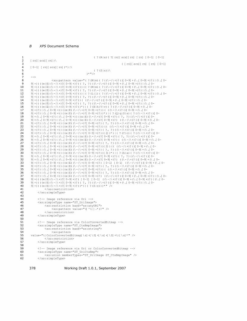
B XPS Document Schema
378 Working Draft 1.0.1, September 2007
( ?(A|a)( ?[rn][scs][rn] [rn] [0-1] [0-1] 1
[rn][scs][rn])\ 2
( [rn][scs][rn] [rn] [0-1] 3
[0-1] [rn][scs][rn])*)|\ 4
( ?(Z|z))\ 5
)*"/> 6
--> 7
<xs:pattern value="( ?(M|m)( ?((\-|\+)?(([0-9]+(\.[0-9]+)?)|(\.[0-8
9]+))((e|E)(\-|\+)?[0-9]+)?)( ?, ?)((\-|\+)?(([0-9]+(\.[0-9]+)?)|(\.[0-9
9]+))((e|E)(\-|\+)?[0-9]+)?)))(( ?(M|m)( ?((\-|\+)?(([0-9]+(\.[0-9]+)?)|(\.[0-10
9]+))((e|E)(\-|\+)?[0-9]+)?)( ?, ?)((\-|\+)?(([0-9]+(\.[0-9]+)?)|(\.[0-11
9]+))((e|E)(\-|\+)?[0-9]+)?)))|( ?(L|l)( ?((\-|\+)?(([0-9]+(\.[0-9]+)?)|(\.[0-12
9]+))((e|E)(\-|\+)?[0-9]+)?)( ?, ?)((\-|\+)?(([0-9]+(\.[0-9]+)?)|(\.[0-13
9]+))((e|E)(\-|\+)?[0-9]+)?))( ((\-|\+)?(([0-9]+(\.[0-9]+)?)|(\.[0-14
9]+))((e|E)(\-|\+)?[0-9]+)?)( ?, ?)((\-|\+)?(([0-9]+(\.[0-9]+)?)|(\.[0-15
9]+))((e|E)(\-|\+)?[0-9]+)?))*)|( ?(H|h|V|v)( ?((\-|\+)?(([0-9]+(\.[0-16
9]+)?)|(\.[0-9]+))((e|E)(\-|\+)?[0-9]+)?))( ((\-|\+)?(([0-9]+(\.[0-17
9]+)?)|(\.[0-9]+))((e|E)(\-|\+)?[0-9]+)?))*)|( ?(Q|q|S|s)( ?((\-|\+)?(([0-18
9]+(\.[0-9]+)?)|(\.[0-9]+))((e|E)(\-|\+)?[0-9]+)?)( ?, ?)((\-|\+)?(([0-19
9]+(\.[0-9]+)?)|(\.[0-9]+))((e|E)(\-|\+)?[0-9]+)?) ((\-|\+)?(([0-9]+(\.[0-20
9]+)?)|(\.[0-9]+))((e|E)(\-|\+)?[0-9]+)?)( ?, ?)((\-|\+)?(([0-9]+(\.[0-21
9]+)?)|(\.[0-9]+))((e|E)(\-|\+)?[0-9]+)?))(( ((\-|\+)?(([0-9]+(\.[0-22
9]+)?)|(\.[0-9]+))((e|E)(\-|\+)?[0-9]+)?)( ?, ?)((\-|\+)?(([0-9]+(\.[0-23
9]+)?)|(\.[0-9]+))((e|E)(\-|\+)?[0-9]+)?)){2})*)|( ?(C|c)( ?((\-|\+)?(([0-24
9]+(\.[0-9]+)?)|(\.[0-9]+))((e|E)(\-|\+)?[0-9]+)?)( ?, ?)((\-|\+)?(([0-25
9]+(\.[0-9]+)?)|(\.[0-9]+))((e|E)(\-|\+)?[0-9]+)?)( ((\-|\+)?(([0-9]+(\.[0-26
9]+)?)|(\.[0-9]+))((e|E)(\-|\+)?[0-9]+)?)( ?, ?)((\-|\+)?(([0-9]+(\.[0-27
9]+)?)|(\.[0-9]+))((e|E)(\-|\+)?[0-9]+)?)){2})(( ((\-|\+)?(([0-9]+(\.[0-28
9]+)?)|(\.[0-9]+))((e|E)(\-|\+)?[0-9]+)?)( ?, ?)((\-|\+)?(([0-9]+(\.[0-29
9]+)?)|(\.[0-9]+))((e|E)(\-|\+)?[0-9]+)?)){3})*)|( ?(A|a)( ?((\-|\+)?(([0-30
9]+(\.[0-9]+)?)|(\.[0-9]+))((e|E)(\-|\+)?[0-9]+)?)( ?, ?)((\-|\+)?(([0-31
9]+(\.[0-9]+)?)|(\.[0-9]+))((e|E)(\-|\+)?[0-9]+)?) ((\-|\+)?(([0-9]+(\.[0-32
9]+)?)|(\.[0-9]+))((e|E)(\-|\+)?[0-9]+)?) [0-1] [0-1] ((\-|\+)?(([0-9]+(\.[0-33
9]+)?)|(\.[0-9]+))((e|E)(\-|\+)?[0-9]+)?)( ?, ?)((\-|\+)?(([0-9]+(\.[0-34
9]+)?)|(\.[0-9]+))((e|E)(\-|\+)?[0-9]+)?))( ((\-|\+)?(([0-9]+(\.[0-35
9]+)?)|(\.[0-9]+))((e|E)(\-|\+)?[0-9]+)?)( ?, ?)((\-|\+)?(([0-9]+(\.[0-36
9]+)?)|(\.[0-9]+))((e|E)(\-|\+)?[0-9]+)?) ((\-|\+)?(([0-9]+(\.[0-9]+)?)|(\.[0-37
9]+))((e|E)(\-|\+)?[0-9]+)?) [0-1] [0-1] ((\-|\+)?(([0-9]+(\.[0-9]+)?)|(\.[0-38
9]+))((e|E)(\-|\+)?[0-9]+)?)( ?, ?)((\-|\+)?(([0-9]+(\.[0-9]+)?)|(\.[0-39
9]+))((e|E)(\-|\+)?[0-9]+)?))*)|( ?(Z|z)))*" /> 40
</xs:restriction> 41
</xs:simpleType> 42
43
<!-- Image reference via Uri --> 44
<xs:simpleType name="ST_UriImage"> 45
<xs:restriction base="xs:anyURI"> 46
<xs:pattern value="([^\{].*)?" /> 47
</xs:restriction> 48
</xs:simpleType> 49
50
<!-- Image reference via ColorConvertedBitmap --> 51
<xs:simpleType name="ST_CtxBmpImage"> 52
<xs:restriction base="xs:string"> 53
<xs:pattern 54
value="\{ColorConvertedBitmap[\s]+[\S]+[\s]+[\S]+\}[\s]*" /> 55
</xs:restriction> 56
</xs:simpleType> 57
58
<!-- Image reference via Uri or ColorConvertedBitmap --> 59
<xs:simpleType name="ST_UriCtxBmp"> 60
<xs:union memberTypes="ST_UriImage ST_CtxBmpImage" /> 61
</xs:simpleType> 62

XPS Specification and Reference Guide B
Working Draft 1.0.1, September 2007 379
1
<!-- Resource reference --> 2
<xs:simpleType name="ST_RscRef"> 3
<xs:restriction base="xs:string"> 4
<xs:pattern value="\{StaticResource[\s]+[\S]+\}[\s]*" /> 5
</xs:restriction> 6
</xs:simpleType> 7
8
<!-- Resource reference OR Color --> 9
<xs:simpleType name="ST_RscRefColor"> 10
<xs:union memberTypes="ST_Color ST_RscRef" /> 11
</xs:simpleType> 12
13
<!-- Resource reference OR Compact Matrix--> 14
<xs:simpleType name="ST_RscRefMatrix"> 15
<xs:union memberTypes="ST_Matrix ST_RscRef" /> 16
</xs:simpleType> 17
18
<!-- Resource reference OR AbbrGeomF--> 19
<xs:simpleType name="ST_RscRefAbbrGeomF"> 20
<xs:union memberTypes="ST_AbbrGeomF ST_RscRef" /> 21
</xs:simpleType> 22
23
<!-- Sweep Direction enumeration --> 24
<xs:simpleType name="ST_SweepDirection"> 25
<xs:restriction base="xs:string"> 26
<xs:enumeration value="Clockwise" /> 27
<xs:enumeration value="Counterclockwise" /> 28
</xs:restriction> 29
</xs:simpleType> 30
31
<!-- Dash Cap enumeration --> 32
<xs:simpleType name="ST_DashCap"> 33
<xs:restriction base="xs:string"> 34
<xs:enumeration value="Flat" /> 35
<xs:enumeration value="Round" /> 36
<xs:enumeration value="Square" /> 37
<xs:enumeration value="Triangle" /> 38
</xs:restriction> 39
</xs:simpleType> 40
41
<!-- Line Cap enumeration --> 42
<xs:simpleType name="ST_LineCap"> 43
<xs:restriction base="xs:string"> 44
<xs:enumeration value="Flat" /> 45
<xs:enumeration value="Round" /> 46
<xs:enumeration value="Square" /> 47
<xs:enumeration value="Triangle" /> 48
</xs:restriction> 49
</xs:simpleType> 50
51
<!-- Line Join enumeration --> 52
<xs:simpleType name="ST_LineJoin"> 53
<xs:restriction base="xs:string"> 54
<xs:enumeration value="Miter" /> 55
<xs:enumeration value="Bevel" /> 56
<xs:enumeration value="Round" /> 57
</xs:restriction> 58
</xs:simpleType> 59
60
<!-- Tile Mode enumeration --> 61
<xs:simpleType name="ST_TileMode"> 62
<xs:restriction base="xs:string"> 63

B XPS Document Schema
380 Working Draft 1.0.1, September 2007
<xs:enumeration value="None" /> 1
<xs:enumeration value="Tile" /> 2
<xs:enumeration value="FlipX" /> 3
<xs:enumeration value="FlipY" /> 4
<xs:enumeration value="FlipXY" /> 5
</xs:restriction> 6
</xs:simpleType> 7
8
<!-- Color Interpolation Mode enumeration --> 9
<xs:simpleType name="ST_ClrIntMode"> 10
<xs:restriction base="xs:string"> 11
<xs:enumeration value="ScRgbLinearInterpolation" /> 12
<xs:enumeration value="SRgbLinearInterpolation" /> 13
</xs:restriction> 14
</xs:simpleType> 15
16
<!-- SpreadMethod Mode enumeration --> 17
<xs:simpleType name="ST_SpreadMethod"> 18
<xs:restriction base="xs:string"> 19
<xs:enumeration value="Pad" /> 20
<xs:enumeration value="Reflect" /> 21
<xs:enumeration value="Repeat" /> 22
</xs:restriction> 23
</xs:simpleType> 24
25
<!-- FillRule Mode enumeration --> 26
<xs:simpleType name="ST_FillRule"> 27
<xs:restriction base="xs:string"> 28
<xs:enumeration value="EvenOdd" /> 29
<xs:enumeration value="NonZero" /> 30
</xs:restriction> 31
</xs:simpleType> 32
33
<!-- Edge Mode enumeration --> 34
<xs:simpleType name="ST_EdgeMode"> 35
<xs:restriction base="xs:string"> 36
<xs:enumeration value="Aliased" /> 37
</xs:restriction> 38
</xs:simpleType> 39
40
<!-- Style Simulation Enumeration --> 41
<xs:simpleType name="ST_StyleSimulations"> 42
<xs:restriction base="xs:string"> 43
<xs:enumeration value="None" /> 44
<xs:enumeration value="ItalicSimulation" /> 45
<xs:enumeration value="BoldSimulation" /> 46
<xs:enumeration value="BoldItalicSimulation" /> 47
</xs:restriction> 48
</xs:simpleType> 49
50
<!-- ViewUnits Enumeration --> 51
<xs:simpleType name="ST_ViewUnits"> 52
<xs:restriction base="xs:string"> 53
<xs:enumeration value="Absolute" /> 54
</xs:restriction> 55
</xs:simpleType> 56
57
<!-- MappingMode Enumeration --> 58
<xs:simpleType name="ST_MappingMode"> 59
<xs:restriction base="xs:string"> 60
<xs:enumeration value="Absolute" /> 61
</xs:restriction> 62

XPS Specification and Reference Guide B
Working Draft 1.0.1, September 2007 381
</xs:simpleType> 1
</xs:schema> 2


XPS Specification and Reference Guide C
Working Draft 1.0.1, September 2007 383
C. Resource Dictionary Key Schema 1
<?xml version="1.0" encoding="utf-8"?> 2
<xs:schema 3
targetNamespace="http://schemas.microsoft.com/xps/2005/06/resourcedictionary-4
key" xmlns="http://schemas.microsoft.com/xps/2005/06/resourcedictionary-key" 5
xmlns:xs="http://www.w3.org/2001/XMLSchema" elementFormDefault="qualified" 6
blockDefault="#all"> 7
8
<xs:attribute name="Key"> 9
<xs:simpleType> 10
<xs:restriction base="xs:string"> 11
<!-- A Key (pattern restriction according to XPS spec) --> 12
<xs:pattern 13
value="(\p{Lu}|\p{Ll}|\p{Lt}|\p{Lo}|\p{Nl}|_)(\p{Lu}|\p{Ll}|\p{Lt}|\p{Lo}|\p{Nl14
}|\p{Mn}|\p{Mc}|\p{Nd}|_)*" /> 15
</xs:restriction> 16
</xs:simpleType> 17
</xs:attribute> 18
19
</xs:schema> 20
21


XPS Specification and Reference Guide D
Working Draft 1.0.1, September 2007 385
D. Document Structure Schema 1
<?xml version="1.0" encoding="UTF-8"?> 2
<xs:schema 3
targetNamespace="http://schemas.microsoft.com/xps/2005/06/documentstructure" 4
xmlns="http://schemas.microsoft.com/xps/2005/06/documentstructure" 5
xmlns:xs="http://www.w3.org/2001/XMLSchema" elementFormDefault="qualified" 6
blockDefault="#all"> 7
8
<xs:import namespace="http://www.w3.org/XML/1998/namespace" /> 9
10
<!-- ============DocumentStructure Part================ --> 11
<!-- Complex Types --> 12
<xs:complexType name="CT_DocumentStructure"> 13
<xs:sequence> 14
<xs:element ref="DocumentStructure.Outline" minOccurs="0" 15
/> 16
<xs:element ref="Story" minOccurs="0" maxOccurs="unbounded" 17
/> 18
</xs:sequence> 19
</xs:complexType> 20
<xs:complexType name="CT_CP_Outline"> 21
<xs:sequence> 22
<xs:element ref="DocumentOutline" /> 23
</xs:sequence> 24
</xs:complexType> 25
<xs:complexType name="CT_DocumentOutline"> 26
<xs:sequence> 27
<xs:element ref="OutlineEntry" maxOccurs="unbounded" /> 28
</xs:sequence> 29
<xs:attributeGroup ref="AG_DocumentOutline" /> 30
</xs:complexType> 31
<xs:complexType name="CT_OutlineEntry"> 32
<xs:attributeGroup ref="AG_OutlineEntry" /> 33
</xs:complexType> 34
<xs:complexType name="CT_Story"> 35
<xs:sequence> 36
<xs:element ref="StoryFragmentReference" 37
maxOccurs="unbounded" /> 38
</xs:sequence> 39
<xs:attributeGroup ref="AG_Story" /> 40
</xs:complexType> 41
<xs:complexType name="CT_StoryFragmentReference"> 42
<xs:attributeGroup ref="AG_StoryFragmentReference" /> 43
</xs:complexType> 44
<!-- Simple Types --> 45
<!-- A Name (ID with pattern restriction according to XPS spec) --> 46
<xs:simpleType name="ST_Name"> 47
<xs:restriction base="xs:string"> 48
<xs:pattern 49
value="(\p{Lu}|\p{Ll}|\p{Lo}|\p{Lt}|\p{Nl})(\p{Lu}|\p{Ll}|\p{Lo}|\p{Lt}|\p{Nl}|50
\p{Mn}|\p{Mc}|\p{Nd}|\p{Lm}|_)*" /> 51
</xs:restriction> 52
</xs:simpleType> 53
<!-- A Unique Name (ID with pattern restriction according to XPS spec) --54
> 55
<xs:simpleType name="ST_NameUnique"> 56
<xs:restriction base="xs:ID"> 57

D Document Structure Schema
386 Working Draft 1.0.1, September 2007
<xs:pattern 1
value="(\p{Lu}|\p{Ll}|\p{Lo}|\p{Lt}|\p{Nl})(\p{Lu}|\p{Ll}|\p{Lo}|\p{Lt}|\p{Nl}|2
\p{Mn}|\p{Mc}|\p{Nd}|\p{Lm}|_)*" /> 3
</xs:restriction> 4
</xs:simpleType> 5
<!-- integer greater than or equal to 1 inclusive --> 6
<xs:simpleType name="ST_IntGEOne"> 7
<xs:restriction base="xs:int"> 8
<xs:minInclusive value="1" /> 9
</xs:restriction> 10
</xs:simpleType> 11
<!-- Elements --> 12
<xs:element name="DocumentStructure" type="CT_DocumentStructure"> 13
</xs:element> 14
<xs:element name="DocumentStructure.Outline" type="CT_CP_Outline"> 15
</xs:element> 16
<xs:element name="DocumentOutline" type="CT_DocumentOutline"> 17
</xs:element> 18
<xs:element name="OutlineEntry" type="CT_OutlineEntry"> 19
</xs:element> 20
<xs:element name="Story" type="CT_Story"> 21
</xs:element> 22
<xs:element name="StoryFragmentReference" 23
type="CT_StoryFragmentReference"> 24
</xs:element> 25
<!-- Attribute Groups --> 26
<xs:attributeGroup name="AG_DocumentOutline"> 27
<xs:attribute ref="xml:lang" use="required"> 28
</xs:attribute> 29
</xs:attributeGroup> 30
<xs:attributeGroup name="AG_OutlineEntry"> 31
<xs:attribute name="OutlineLevel" type="ST_IntGEOne" 32
use="optional" default="1"> 33
</xs:attribute> 34
<xs:attribute name="OutlineTarget" type="xs:anyURI" 35
use="required"> 36
</xs:attribute> 37
<xs:attribute name="Description" type="xs:string" use="required"> 38
</xs:attribute> 39
<xs:attribute ref="xml:lang" use="optional"> 40
</xs:attribute> 41
</xs:attributeGroup> 42
<xs:attributeGroup name="AG_Story"> 43
<xs:attribute name="StoryName" type="xs:string" use="required"> 44
</xs:attribute> 45
</xs:attributeGroup> 46
<xs:attributeGroup name="AG_StoryFragmentReference"> 47
<xs:attribute name="FragmentName" type="xs:string" use="optional"> 48
</xs:attribute> 49
<xs:attribute name="Page" type="ST_IntGEOne" use="required"> 50
</xs:attribute> 51
</xs:attributeGroup> 52
<!-- ================StoryFragments Part============== --> 53
<!-- Complex Types --> 54
<xs:complexType name="CT_StoryFragments"> 55
<xs:sequence> 56
<xs:element ref="StoryFragment" maxOccurs="unbounded" /> 57
</xs:sequence> 58
</xs:complexType> 59
<xs:complexType name="CT_StoryFragment"> 60
<xs:sequence> 61
<xs:element ref="StoryBreak" minOccurs="0" /> 62

XPS Specification and Reference Guide D
Working Draft 1.0.1, September 2007 387
<xs:choice maxOccurs="unbounded"> 1
<xs:element ref="SectionStructure" /> 2
<xs:element ref="ParagraphStructure" /> 3
<xs:element ref="ListStructure" /> 4
<xs:element ref="TableStructure" /> 5
<xs:element ref="FigureStructure" /> 6
</xs:choice> 7
<xs:element ref="StoryBreak" minOccurs="0" /> 8
</xs:sequence> 9
<xs:attributeGroup ref="AG_StoryFragment" /> 10
</xs:complexType> 11
<xs:complexType name="CT_Break"> 12
</xs:complexType> 13
<xs:complexType name="CT_Section"> 14
<xs:choice maxOccurs="unbounded"> 15
<xs:element ref="ParagraphStructure" /> 16
<xs:element ref="ListStructure" /> 17
<xs:element ref="TableStructure" /> 18
<xs:element ref="FigureStructure" /> 19
</xs:choice> 20
</xs:complexType> 21
<xs:complexType name="CT_Paragraph"> 22
<xs:choice minOccurs="0" maxOccurs="unbounded"> 23
<xs:element ref="NamedElement" /> 24
</xs:choice> 25
</xs:complexType> 26
<xs:complexType name="CT_Table"> 27
<xs:choice maxOccurs="unbounded"> 28
<xs:element ref="TableRowGroupStructure" /> 29
</xs:choice> 30
</xs:complexType> 31
<xs:complexType name="CT_TableRowGroup"> 32
<xs:choice maxOccurs="unbounded"> 33
<xs:element ref="TableRowStructure" /> 34
</xs:choice> 35
</xs:complexType> 36
<xs:complexType name="CT_TableRow"> 37
<xs:choice maxOccurs="unbounded"> 38
<xs:element ref="TableCellStructure" /> 39
</xs:choice> 40
</xs:complexType> 41
<xs:complexType name="CT_TableCell"> 42
<xs:choice minOccurs="0" maxOccurs="unbounded"> 43
<xs:element ref="ParagraphStructure" /> 44
<xs:element ref="ListStructure" /> 45
<xs:element ref="TableStructure" /> 46
<xs:element ref="FigureStructure" /> 47
</xs:choice> 48
<xs:attributeGroup ref="AG_TableCell" /> 49
</xs:complexType> 50
<xs:complexType name="CT_List"> 51
<xs:choice maxOccurs="unbounded"> 52
<xs:element ref="ListItemStructure" /> 53
</xs:choice> 54
</xs:complexType> 55
<xs:complexType name="CT_ListItem"> 56
<xs:choice minOccurs="0" maxOccurs="unbounded"> 57
<xs:element ref="ParagraphStructure" /> 58
<xs:element ref="ListStructure" /> 59
<xs:element ref="TableStructure" /> 60
<xs:element ref="FigureStructure" /> 61
</xs:choice> 62
<xs:attributeGroup ref="AG_ListItem" /> 63

D Document Structure Schema
388 Working Draft 1.0.1, September 2007
</xs:complexType> 1
<xs:complexType name="CT_Figure"> 2
<xs:choice minOccurs="0" maxOccurs="unbounded"> 3
<xs:element ref="NamedElement" /> 4
</xs:choice> 5
</xs:complexType> 6
<xs:complexType name="CT_NamedElement"> 7
<xs:attributeGroup ref="AG_NamedElement" /> 8
</xs:complexType> 9
<!-- Simple Types --> 10
<!-- FragmentType enumeration --> 11
<xs:simpleType name="ST_FragmentType"> 12
<xs:restriction base="xs:string"> 13
<xs:enumeration value="Content" /> 14
<xs:enumeration value="Header" /> 15
<xs:enumeration value="Footer" /> 16
</xs:restriction> 17
</xs:simpleType> 18
<xs:simpleType name="ST_Location"> 19
<xs:restriction base="xs:string"> 20
<xs:pattern value="([0-9][0-9]*)(\,[0-9][0-9]*)*" /> 21
</xs:restriction> 22
</xs:simpleType> 23
<xs:simpleType name="ST_TableSpan"> 24
<xs:restriction base="xs:int"> 25
<xs:minInclusive value="1" /> 26
</xs:restriction> 27
</xs:simpleType> 28
<xs:simpleType name="ST_ElementIndex"> 29
<xs:restriction base="xs:int"> 30
<xs:minInclusive value="0" /> 31
</xs:restriction> 32
</xs:simpleType> 33
<!-- Elements --> 34
<xs:element name="StoryFragments" type="CT_StoryFragments"> 35
</xs:element> 36
<xs:element name="StoryFragment" type="CT_StoryFragment"> 37
</xs:element> 38
<xs:element name="StoryBreak" type="CT_Break"> 39
</xs:element> 40
<xs:element name="SectionStructure" type="CT_Section"> 41
</xs:element> 42
<xs:element name="ParagraphStructure" type="CT_Paragraph"> 43
</xs:element> 44
<xs:element name="TableStructure" type="CT_Table"> 45
</xs:element> 46
<xs:element name="TableRowGroupStructure" type="CT_TableRowGroup"> 47
</xs:element> 48
<xs:element name="TableRowStructure" type="CT_TableRow"> 49
</xs:element> 50
<xs:element name="TableCellStructure" type="CT_TableCell"> 51
</xs:element> 52
<xs:element name="ListStructure" type="CT_List"> 53
</xs:element> 54
<xs:element name="ListItemStructure" type="CT_ListItem"> 55
</xs:element> 56
<xs:element name="FigureStructure" type="CT_Figure"> 57
</xs:element> 58
<xs:element name="NamedElement" type="CT_NamedElement"> 59
</xs:element> 60
<!-- Attribute Groups --> 61
<xs:attributeGroup name="AG_StoryFragment"> 62

XPS Specification and Reference Guide D
Working Draft 1.0.1, September 2007 389
<xs:attribute name="StoryName" type="xs:string" use="optional"> 1
</xs:attribute> 2
<xs:attribute name="FragmentName" type="xs:string" use="optional"> 3
</xs:attribute> 4
<xs:attribute name="FragmentType" type="ST_FragmentType" 5
use="required"> 6
</xs:attribute> 7
</xs:attributeGroup> 8
<xs:attributeGroup name="AG_TableCell"> 9
<xs:attribute name="RowSpan" type="ST_TableSpan" use="optional" 10
default="1"> 11
</xs:attribute> 12
<xs:attribute name="ColumnSpan" type="ST_TableSpan" use="optional" 13
default="1"> 14
</xs:attribute> 15
</xs:attributeGroup> 16
<xs:attributeGroup name="AG_ListItem"> 17
<xs:attribute name="Marker" type="ST_NameUnique" use="optional"> 18
</xs:attribute> 19
</xs:attributeGroup> 20
<xs:attributeGroup name="AG_NamedElement"> 21
<xs:attribute name="NameReference" type="ST_Name" use="required"> 22
</xs:attribute> 23
</xs:attributeGroup> 24
</xs:schema> 25
26
27


XPS Specification and Reference Guide E
Working Draft 1.0.1, September 2007 391
E. Discard Control Schema 1
<?xml version="1.0" encoding="UTF-8"?> 2
<xs:schema targetNamespace="http://schemas.microsoft.com/xps/2005/06/discard-3
control" xmlns="http://schemas.microsoft.com/xps/2005/06/discard-control" 4
xmlns:xs="http://www.w3.org/2001/XMLSchema" elementFormDefault="qualified" 5
blockDefault="#all"> 6
7
<xs:complexType name="CT_DiscardControl"> 8
<xs:sequence> 9
<xs:element ref="Discard" minOccurs="0" 10
maxOccurs="unbounded" /> 11
</xs:sequence> 12
</xs:complexType> 13
14
<xs:complexType name="CT_Discard"> 15
<xs:attribute name="SentinelPage" type="xs:anyURI" use="required"> 16
</xs:attribute> 17
<xs:attribute name="Target" type="xs:anyURI" use="required"> 18
</xs:attribute> 19
</xs:complexType> 20
21
<xs:element name="DiscardControl" type="CT_DiscardControl"> 22
</xs:element> 23
24
<xs:element name="Discard" type="CT_Discard"> 25
</xs:element> 26
27
</xs:schema> 28
29
30


XPS Specification and Reference Guide F
Working Draft 1.0.1, September 2007 393
F. Abbreviated Geometry Syntax Algorithm 1
A path geometry specified using the abbreviated geometry syntax (see §11.2.3, 2
―Abbreviated Geometry Syntax,‖ on page 90) is equivalent to a path specified using 3
a path geometry. The following algorithm describes how the abbreviated path syntax 4
can be transformed into a path geometry containing path figures that, in turn, 5
contain various segments. 6
This algorithm assumes that the presented string is well-formed according to the 7
markup schema. Whitespace skipping is assumed without being explicitly spelled out 8
in the algorithm. 9
10
Let CURRENTPOINT = 0,0 11 Create a new PathGeometry PG 12 PG.FillRule = EvenOdd 13 Let CURRENTPATHFIGURE = undefined 14 15 Read input character CH 16 17 if ( CH == 'F' ) 18 { 19 Read input character CH 20 if ( CH == '0' ) 21 { 22 PG.FillRule = EvenOdd 23 } 24 else 25 { 26 PG.FillRule = NonZero 27 } 28 } 29 else 30 { 31 GOTO label_first 32 } 33 34 label_repeat: 35 Read input character CH 36 37 label_first: 38 39 if ( CH == 'm' ) 40 { 41 Read relative coordinate pair DX,DY 42 Let CURRENTPOINT.X = CURRENTPOINT.X + DX 43 Let CURRENTPOINT.Y = CURRENTPOINT.Y + DY 44 Create a new PathFigure CURRENTPATHFIGURE and add to PG 45 Let attribute CURRENTPATHFIGURE.StartPoint = CURRENTPOINT 46 } 47 else if ( CH == 'M' ) 48 { 49 Read coordinate pair X,Y 50 Let CURRENTPOINT.X = X 51 Let CURRENTPOINT.Y = Y 52 Create a new PathFigure CURRENTPATHFIGURE and add to PG 53 Let attribute CURRENTPATHFIGURE.StartPoint = CURRENTPOINT 54 } 55 else if ( CH == 'l' ) 56 { 57 Create new PolyLineSegment S 58 Add S to CURRENTPATHFIGURE 59 label_1: 60

F Abbreviated Geometry Syntax Algorithm
394 Working Draft 1.0.1, September 2007
Read relative coordinate pair DX,DY 1 Let CURRENTPOINT.X = CURRENTPOINT.X + DX 2 Let CURRENTPOINT.Y = CURRENTPOINT.Y + DY 3 Add CURRENTPOINT.X,CURRENTPOINT.Y to end of S.Points attribute list 4 if ( next character is not a letter ) 5 { 6 GOTO label_1 7 } 8 } 9 else if ( CH == 'L' ) 10 { 11 Create new PolyLineSegment S 12 Add S to CURRENTPATHFIGURE 13 label_2: 14 Read coordinate pair X,Y 15 Let CURRENTPOINT.X = X 16 Let CURRENTPOINT.Y = Y 17 Add CURRENTPOINT.X,CURRENTPOINT.Y to end of S.Points attribute list 18 if ( next character is not a letter ) 19 { 20 GOTO label_2 21 } 22 } 23 else if ( CH == 'h' ) 24 { 25 Create new PolyLineSegment S 26 Add S to CURRENTPATHFIGURE 27 label_3: 28 Read relative coordinate value DX 29 Let CURRENTPOINT.X = CURRENTPOINT.X + DX 30 Add CURRENTPOINT.X,CURRENTPOINT.Y to end of S.Points attribute list 31 if ( next character is not a letter ) 32 { 33 GOTO label_3 34 } 35 } 36 else if ( CH == 'H' ) 37 { 38 Create new PolyLineSegment S 39 Add S to CURRENTPATHFIGURE 40 label_4: 41 Read coordinate value X 42 Let CURRENTPOINT.X = X 43 Add CURRENTPOINT.X,CURRENTPOINT.Y to end of S.Points attribute list 44 if ( next character is not a letter ) 45 { 46 GOTO label_4 47 } 48 } 49 else if ( CH == 'v' ) 50 { 51 Create new PolyLineSegment S 52 Add S to CURRENTPATHFIGURE 53 label_5: 54 Read relative coordinate value DY 55 Let CURRENTPOINT.Y = CURRENTPOINT.Y + DY 56 Add CURRENTPOINT.X,CURRENTPOINT.Y to end of S.Points attribute list 57 if ( next character is not a letter ) 58 { 59 GOTO label_5 60 } 61 } 62 else if ( CH == 'V' ) 63 { 64 Create new PolyLineSegment S 65 Add S to CURRENTPATHFIGURE 66 label_6: 67 Read coordinate value Y 68 Let CURRENTPOINT.Y = Y 69 Add CURRENTPOINT.X,CURRENTPOINT.Y to end of S.Points attribute list 70

XPS Specification and Reference Guide F
Working Draft 1.0.1, September 2007 395
if ( next character is not a letter ) 1 { 2 GOTO label_6 3 } 4 } 5 else if ( CH == 'c' ) 6 { 7 Create new PolyBezierSegment S 8 Add S to CURRENTPATHFIGURE 9 label_7: 10 Read relative coordinate pair DX,DY 11 Let POINT.X = CURRENTPOINT.X + DX 12 Let POINT.Y = CURRENTPOINT.Y + DY 13 Add POINT.X, POINT.Y to end of S.Points attribute list 14 Read coordinate pair DX,DY 15 Let POINT.X = CURRENTPOINT.X + DX 16 Let POINT.Y = CURRENTPOINT.Y + DY 17 Add POINT.X, POINT.Y to end of S.Points attribute list 18 Read coordinate pair DX,DY 19 Let CURRENTPOINT.X = CURRENTPOINT.X + DX 20 Let CURRENTPOINT.Y = CURRENTPOINT.Y + DY 21 Add CURRENTPOINT.X,CURRENTPOINT.Y to end of S.Points attribute list 22 if ( next character is not a letter ) 23 { 24 GOTO label_7 25 } 26 } 27 else if ( CH == 'C' ) 28 { 29 Create new PolyBezierSegment S 30 Add S to CURRENTPATHFIGURE 31 label_8: 32 Read coordinate pair X,Y 33 Let POINT.X = X 34 Let POINT.Y = Y 35 Add POINT.X, POINT.Y to end of S.Points attribute list 36 Read coordinate pair X,Y 37 Let POINT.X = X 38 Let POINT.Y = Y 39
Add POINT.X, POINT.Y to end of S.Points attribute list 40 Read coordinate pair X,Y 41 Let CURRENTPOINT.X = X 42 Let CURRENTPOINT.Y = Y 43 Add CURRENTPOINT.X,CURRENTPOINT.Y to end of S.Points attribute list 44 if ( next character is not a letter ) 45 { 46 GOTO label_8 47 } 48 } 49 else if ( CH == 'q' ) 50 { 51 Create new PolyQuadraticBezierSegment S 52 Add S to CURRENTPATHFIGURE 53 label_9: 54 Read relative coordinate pair DX,DY 55 Let POINT.X = CURRENTPOINT.X + DX 56 Let POINT.Y = CURRENTPOINT.Y + DY 57 Add POINT.X, POINT.Y to end of S.Points attribute list 58 Read relative coordinate pair DX,DY 59 Let CURRENTPOINT.X = CURRENTPOINT.X + DX 60 Let CURRENTPOINT.Y = CURRENTPOINT.Y + DY 61 Add CURRENTPOINT.X,CURRENTPOINT.Y to end of S.Points attribute list 62 if ( next character is not a letter ) 63 { 64 GOTO label_9 65 } 66 } 67 else ( if CH == 'Q' ) 68 { 69 Create new PolyQuadraticBezierSegment S 70 Add S to CURRENTPATHFIGURE 71
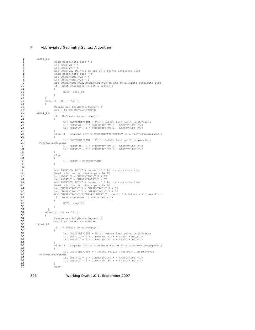
F Abbreviated Geometry Syntax Algorithm
396 Working Draft 1.0.1, September 2007
label_10: 1 Read coordinate pair X,Y 2 Let POINT.X = X 3 Let POINT.Y = Y 4 Add POINT.X, POINT.Y to end of S.Points attribute list 5 Read coordinate pair X,Y 6 Let CURRENTPOINT.X = X 7 Let CURRENTPOINT.Y = Y 8 Add CURRENTPOINT.X,CURRENTPOINT.Y to end of S.Points attribute list 9 if ( next character is not a letter ) 10 { 11 GOTO label_10 12 } 13 } 14 else if ( CH == 's' ) 15 { 16 Create new PolyBezierSegment S 17 Add S to CURRENTPATHFIGURE 18 label_11: 19 if ( S.Points is non-empty ) 20 { 21 Let LASTCTRLPOINT = Point before last point in S.Points 22 Let POINT.X = 2 * CURRENTPOINT.X - LASTCTRLPOINT.X 23 Let POINT.Y = 2 * CURRENTPOINT.Y - LASTCTRLPOINT.Y 24 } 25 else if ( segment before CURRENTPATHSEGMENT is a PolyBezierSegment ) 26 { 27 Let LASTCTRLPOINT = Point before last point in previous 28 PolyBezierSegment 29
Let POINT.X = 2 * CURRENTPOINT.X - LASTCTRLPOINT.X 30 Let POINT.Y = 2 * CURRENTPOINT.Y - LASTCTRLPOINT.Y 31 } 32 else 33 { 34 Let POINT = CURRENTPOINT 35 } 36 37 Add POINT.X, POINT.Y to end of S.Points attribute list 38 Read relative coordinate pair DX,DY 39 Let POINT.X = CURRENTPOINT.X + DX 40 Let POINT.Y = CURRENTPOINT.Y + DY 41 Add POINT.X, POINT.Y to end of S.Points attribute list 42 Read relative coordinate pair DX,DY 43 Let CURRENTPOINT.X = CURRENTPOINT.X + DX 44 Let CURRENTPOINT.Y = CURRENTPOINT.Y + DY 45 Add CURRENTPOINT.X,CURRENTPOINT.Y to end of S.Points attribute list 46 if ( next character is not a letter ) 47 { 48 GOTO label_11 49 } 50 } 51 else if ( CH == 'S' ) 52 { 53 Create new PolyBezierSegment S 54 Add S to CURRENTPATHFIGURE 55 label_12: 56 if ( S.Points is non-empty ) 57 { 58 Let LASTCTRLPOINT = Point before last point in S.Points 59 Let POINT.X = 2 * CURRENTPOINT.X - LASTCTRLPOINT.X 60 Let POINT.Y = 2 * CURRENTPOINT.Y - LASTCTRLPOINT.Y 61 } 62 else if ( segment before CURRENTPATHSEGMENT is a PolyBezierSegment ) 63 { 64 Let LASTCTRLPOINT = S.Point before last point in previous 65 PolyBezierSegment 66
Let POINT.X = 2 * CURRENTPOINT.X - LASTCTRLPOINT.X 67 Let POINT.Y = 2 * CURRENTPOINT.Y - LASTCTRLPOINT.Y 68 } 69 else 70

XPS Specification and Reference Guide F
Working Draft 1.0.1, September 2007 397
{ 1 Let POINT = CURRENTPOINT 2 } 3 4 Add POINT.X, POINT.Y to end of S.Points attribute list 5 Read coordinate pair X,Y 6 Let POINT.X = X 7 Let POINT.Y = Y 8 Add POINT.X, POINT.Y to end of S.Points attribute list 9 Read coordinate pair X,Y 10 Let CURRENTPOINT.X = X 11 Let CURRENTPOINT.Y = Y 12 Add CURRENTPOINT.X,CURRENTPOINT.Y to end of S.Points attribute list 13 if ( next character is not a letter ) 14 { 15 GOTO label_12 16 } 17 } 18 else if ( CH == 'a' ) 19 { 20 label_13: 21 Create new ArcSegment S 22 Add S to CURRENTPATHFIGURE 23 Read Radius Pair RX,RY 24 Read Rotation ROT 25 Read integer FLAG1 26 Read integer FLAG2 27 Read relative coordinate pair DX,DY 28 Let CURRENTPOINT.X = CURRENTPOINT.X + DX 29 Let CURRENTPOINT.Y = CURRENTPOINT.Y + DY 30 Let S.Point = CURRENTPOINT.X,CURRENTPOINT.Y 31 Let S.IsLargeArc = (FLAG1 == 1 ? true : false) 32 Let S.SweepDirection = (FLAG2 == 1 ? Clockwise : Counterclockwise) 33 Let S.RotationAngle = ROT 34 Let S.Size = RX, RY 35 if ( next character is not a letter ) 36 { 37 GOTO label_13 38 } 39 } 40 else if ( CH == 'A' ) 41 { 42 label_14: 43 Create new ArcSegment S 44 Add S to CURRENTPATHFIGURE 45 Read Radius Pair RX,RY 46 Read Rotation ROT 47 Read integer FLAG1 48 Read integer FLAG2 49 Read coordinate pair X,Y 50 Let CURRENTPOINT.X = X 51 Let CURRENTPOINT.Y = Y 52 Let S.Point = CURRENTPOINT.X,CURRENTPOINT.Y 53 Let S.IsLargeArc = (FLAG1 == 1 ? true : false) 54 Let S.SweepDirection = (FLAG2 == 1 ? Clockwise : Counterclockwise) 55 Let S.RotationAngle = ROT 56 Let S.Size = RX, RY 57 if ( next character is not a letter ) 58 { 59 GOTO label_14 60 } 61 } 62 else if ( CH == 'z' or CH == 'Z' ) 63 { 64 Let attribute CURRENTPATHFIGURE.IsClosed = true 65 Left CURRENTPOINT = First point of first segment of CURRENTPATHFIGURE 66 Let CURRENTPATHFIGURE = undefined 67 } 68 /* This case can not occur, because the input is assumed to be well-formed 69 according to the markup schema 70
else 71

F Abbreviated Geometry Syntax Algorithm
398 Working Draft 1.0.1, September 2007
{ 1 ERROR: Invalid input character 2 } 3 */ 4 5 if ( End of input reached ) 6 { 7 Terminate algorithm, return PG 8 } 9 else 10 { 11 GOTO label_repeat 12 } 13
14

XPS Specification and Reference Guide G
Working Draft 1.0.1, September 2007 399
G. scRGB Gamut Boundary Definition 1
<?xml version="1.0" encoding="utf-8" ?> 2
<cdm:ColorDeviceModel 3
ID="http://schemas.microsoft.com/windows/2005/02/color/wcsRGB.cdmp" 4
xmlns:cdm="http://schemas.microsoft.com/windows/2005/02/color/ 5
ColorDeviceModel" 6
xmlns:wcs="http://schemas.microsoft.com/windows/2005/02/color/ 7
WcsCommonProfileTypes" 8
xmlns:xs='http://www.w3.org/2001/XMLSchema-instance'> 9
10
<cdm:ProfileName> 11
<wcs:Text xml:lang="en-US">wcsRGB virtual device model profile</wcs:Text> 12
</cdm:ProfileName> 13
<cdm:Description> 14
<wcs:Text xml:lang="en-US">wcsRGB virtual s2.13 device model system 15
profile</wcs:Text> 16
</cdm:Description> 17
<cdm:Author> 18
<wcs:Text xml:lang="en-US">Microsoft Corporation</wcs:Text> 19
</cdm:Author> 20
21
<cdm:MeasurementConditions> 22
<cdm:ColorSpace>CIEXYZ</cdm:ColorSpace> 23
<cdm:WhitePointName>D65</cdm:WhitePointName> 24
</cdm:MeasurementConditions> 25
<cdm:SelfLuminous>true</cdm:SelfLuminous> 26
<cdm:MaxColorant>4.0</cdm:MaxColorant> 27
<cdm:MinColorant>-4.0</cdm:MinColorant> 28
29
<cdm:RGBVirtualDevice> 30
<cdm:MeasurementData TimeStamp="2005-02-09T22:00:00"> 31
<cdm:WhitePrimary X="95.05" Y="100.00" Z="108.90" /> 32
<cdm:RedPrimary X="41.24" Y="21.26" Z="1.93" /> 33
<cdm:GreenPrimary X="35.76" Y="71.52" Z="11.92" /> 34
<cdm:BluePrimary X="18.05" Y="7.22" Z="95.05" /> 35
<cdm:BlackPrimary X="0" Y="0" Z="0" /> 36
<cdm:Gamma value="1.0" /> 37
<cdm:GamutBoundarySamples> 38
<cdm:RGB R="0.166433" G="-0.016114" B="0.027918" /> 39
<cdm:RGB R="0.257134" G="-0.026542" B="0.041950" /> 40
<cdm:RGB R="0.373396" G="-0.039395" B="0.060310" /> 41
<cdm:RGB R="0.516590" G="-0.054207" B="0.083665" /> 42
<cdm:RGB R="0.161885" G="-0.013701" B="0.015224" /> 43
<cdm:RGB R="0.254873" G="-0.024242" B="0.022314" /> 44
<cdm:RGB R="0.370591" G="-0.036207" B="0.031873" /> 45
<cdm:RGB R="0.645317" G="-0.053422" B="0.061566" /> 46
<cdm:RGB R="0.246052" G="-0.020570" B="0.009804" /> 47
<cdm:RGB R="0.366951" G="-0.033595" B="0.013350" /> 48
<cdm:RGB R="0.513086" G="-0.047777" B="0.018342" /> 49
<cdm:RGB R="0.348159" G="-0.027092" B="0.002697" /> 50
<cdm:RGB R="0.501415" G="-0.043030" B="0.003038" /> 51
<cdm:RGB R="0.204158" G="-0.007054" B="-0.001921" /> 52
<cdm:RGB R="0.102843" G="0.005460" B="-0.002574" /> 53
<cdm:RGB R="0.161680" G="0.005828" B="-0.003751" /> 54
<cdm:RGB R="0.241218" G="0.005609" B="-0.005263" /> 55
<cdm:RGB R="0.345298" G="0.004589" B="-0.007162" /> 56
<cdm:RGB R="1.381166" G="0.758736" B="0.088389" /> 57
<cdm:RGB R="0.747224" G="0.490147" B="-0.065045" /> 58

G scRGB Gamut Boundary Definition
400 Working Draft 1.0.1, September 2007
<cdm:RGB R="0.892023" G="0.585517" B="-0.076908" /> 1
<cdm:RGB R="1.054700" G="0.693668" B="-0.087994" /> 2
<cdm:RGB R="1.237403" G="0.815408" B="-0.099715" /> 3
<cdm:RGB R="0.429786" G="0.463528" B="-0.056073" /> 4
<cdm:RGB R="0.109329" G="0.215829" B="-0.023359" /> 5
<cdm:RGB R="0.170974" G="0.342970" B="-0.037798" /> 6
<cdm:RGB R="0.032781" G="0.182702" B="-0.017604" /> 7
<cdm:RGB R="0.040703" G="0.236387" B="-0.023182" /> 8
<cdm:RGB R="0.052010" G="0.299807" B="-0.029289" /> 9
<cdm:RGB R="-0.015232" G="0.150695" B="-0.012907" /> 10
<cdm:RGB R="-0.020689" G="0.198705" B="-0.017162" /> 11
<cdm:RGB R="-0.086126" G="0.133080" B="0.007658" /> 12
<cdm:RGB R="-0.178409" G="0.235796" B="0.126003" /> 13
<cdm:RGB R="0.000000" G="0.000000" B="0.000000" /> 14
<cdm:RGB R="-0.150496" G="0.178902" B="0.156523" /> 15
<cdm:RGB R="-0.193313" G="0.234293" B="0.204426" /> 16
<cdm:RGB R="-0.202798" G="0.230449" B="0.290886" /> 17
<cdm:RGB R="-0.211558" G="0.225780" B="0.384316" /> 18
<cdm:RGB R="-0.249008" G="0.286162" B="0.470316" /> 19
<cdm:RGB R="1.024267" G="0.995126" B="0.956518" /> 20
<cdm:RGB R="-0.211156" G="0.218574" B="0.473918" /> 21
<cdm:RGB R="-0.209022" G="0.210461" B="0.567755" /> 22
<cdm:RGB R="0.368209" G="0.814614" B="1.020972" /> 23
<cdm:RGB R="-0.194449" G="0.199547" B="0.648518" /> 24
<cdm:RGB R="0.099507" G="0.602350" B="1.001310" /> 25
<cdm:RGB R="0.447496" G="0.790515" B="1.022822" /> 26
<cdm:RGB R="-0.123046" G="0.108061" B="0.470343" /> 27
<cdm:RGB R="-0.150585" G="0.144010" B="0.596962" /> 28
<cdm:RGB R="0.185831" G="0.575754" B="1.007060" /> 29
<cdm:RGB R="0.331216" G="0.668936" B="1.023494" /> 30
<cdm:RGB R="0.410196" G="0.645807" B="1.014063" /> 31
<cdm:RGB R="0.574938" G="0.752116" B="1.021593" /> 32
<cdm:RGB R="0.483140" G="0.624458" B="1.005310" /> 33
<cdm:RGB R="0.635447" G="0.734762" B="1.010061" /> 34
<cdm:RGB R="-0.052205" G="0.035138" B="0.436365" /> 35
<cdm:RGB R="1.024267" G="0.995126" B="0.956518" /> 36
<cdm:RGB R="0.028844" G="-0.005277" B="0.123163" /> 37
<cdm:RGB R="0.049636" G="-0.010904" B="0.228673" /> 38
<cdm:RGB R="0.080157" G="-0.012435" B="0.135751" /> 39
<cdm:RGB R="0.127487" G="-0.020154" B="0.216960" /> 40
<cdm:RGB R="0.190206" G="-0.029844" B="0.323182" /> 41
<cdm:RGB R="0.097580" G="-0.013313" B="0.083401" /> 42
<cdm:RGB R="0.155931" G="-0.021750" B="0.133422" /> 43
<cdm:RGB R="0.230038" G="-0.031267" B="0.196426" /> 44
<cdm:RGB R="0.326426" G="-0.043430" B="0.278289" /> 45
<cdm:RGB R="0.426090" G="-0.050043" B="0.360668" /> 46
<cdm:RGB R="0.098869" G="-0.010753" B="0.048113" /> 47
<cdm:RGB R="0.164545" G="-0.019812" B="0.079230" /> 48
<cdm:RGB R="0.249557" G="-0.030741" B="0.119834" /> 49
<cdm:RGB R="0.357564" G="-0.043900" B="0.171719" /> 50
<cdm:RGB R="0.495437" G="-0.060672" B="0.237960" /> 51
<cdm:RGB R="0.619457" G="-0.065550" B="0.301872" /> 52
<cdm:RGB R="0.000000" G="0.000000" B="0.000000" /> 53
<cdm:RGB R="0.169101" G="-0.018572" B="0.047904" /> 54
<cdm:RGB R="0.255247" G="-0.028467" B="0.071995" /> 55
<cdm:RGB R="0.368932" G="-0.041653" B="0.103698" /> 56
<cdm:RGB R="0.508606" G="-0.056762" B="0.143412" /> 57
<cdm:RGB R="0.637110" G="-0.061275" B="0.186481" /> 58
<cdm:RGB R="1.249149" G="-0.024436" B="-0.002194" /> 59
<cdm:RGB R="0.000475" G="-0.001355" B="0.043728" /> 60
<cdm:RGB R="1.257972" G="-0.026125" B="0.049916" /> 61
<cdm:RGB R="1.264195" G="-0.027432" B="0.104713" /> 62

XPS Specification and Reference Guide G
Working Draft 1.0.1, September 2007 401
<cdm:RGB R="0.003291" G="-0.009926" B="0.365422" /> 1
<cdm:RGB R="1.287764" G="-0.033804" B="0.414704" /> 2
<cdm:RGB R="0.004536" G="-0.013745" B="0.512430" /> 3
<cdm:RGB R="1.297183" G="-0.037024" B="0.573653" /> 4
<cdm:RGB R="1.307374" G="-0.040929" B="0.763754" /> 5
<cdm:RGB R="0.007818" G="-0.023805" B="0.902837" /> 6
<cdm:RGB R="-0.001325" G="0.002612" B="-0.000199" /> 7
<cdm:RGB R="-0.007337" G="0.015263" B="-0.001058" /> 8
<cdm:RGB R="-0.005430" G="-0.000728" B="0.906022" /> 9
<cdm:RGB R="-0.020327" G="0.043021" B="-0.002887" /> 10
<cdm:RGB R="-0.042091" G="0.089818" B="-0.005932" /> 11
<cdm:RGB R="-0.117963" G="0.253649" B="-0.016500" /> 12
<cdm:RGB R="-0.141327" G="0.262090" B="0.943868" /> 13
<cdm:RGB R="-0.174730" G="0.376455" B="-0.024386" /> 14
<cdm:RGB R="-0.204641" G="0.390245" B="0.954021" /> 15
<cdm:RGB R="-0.245665" G="0.530007" B="-0.034229" /> 16
<cdm:RGB R="-0.282073" G="0.548898" B="0.962351" /> 17
<cdm:RGB R="1.150086" G="0.568927" B="1.001779" /> 18
<cdm:RGB R="-0.374737" G="0.740509" B="0.968358" /> 19
<cdm:RGB R="1.083883" G="0.766726" B="1.001175" /> 20
<cdm:RGB R="1.002593" G="0.985026" B="-0.073045" /> 21
<cdm:RGB R="-0.434478" G="0.938894" B="-0.060390" /> 22
<cdm:RGB R="0.000055" G="-0.000136" B="0.003135" /> 23
<cdm:RGB R="0.000203" G="-0.000555" B="0.016188" /> 24
<cdm:RGB R="0.000896" G="-0.002619" B="0.089419" /> 25
<cdm:RGB R="0.001492" G="-0.004425" B="0.156418" /> 26
<cdm:RGB R="0.002283" G="-0.006839" B="0.247555" /> 27
<cdm:RGB R="0.006038" G="-0.018353" B="0.690852" /> 28
<cdm:RGB R="0.007818" G="-0.023805" B="0.902837" /> 29
<cdm:RGB R="-0.483692" G="0.967403" B="0.971726" /> 30
<cdm:RGB R="0.003728" G="-0.000194" B="0.002807" /> 31
<cdm:RGB R="0.004140" G="-0.000555" B="0.015782" /> 32
<cdm:RGB R="0.004738" G="-0.001328" B="0.043372" /> 33
<cdm:RGB R="0.005489" G="-0.002582" B="0.089155" /> 34
<cdm:RGB R="0.006397" G="-0.004383" B="0.156254" /> 35
<cdm:RGB R="0.007479" G="-0.006795" B="0.247483" /> 36
<cdm:RGB R="0.008758" G="-0.009881" B="0.365433" /> 37
<cdm:RGB R="0.010255" G="-0.013700" B="0.512516" /> 38
<cdm:RGB R="0.011993" G="-0.018308" B="0.691003" /> 39
<cdm:RGB R="0.013995" G="-0.023760" B="0.903048" /> 40
<cdm:RGB R="0.034050" G="-0.018254" B="0.692249" /> 41
<cdm:RGB R="0.036746" G="-0.023689" B="0.904397" /> 42
<cdm:RGB R="0.080545" G="-0.023830" B="0.908226" /> 43
<cdm:RGB R="0.149752" G="-0.024452" B="0.915123" /> 44
<cdm:RGB R="1.002593" G="0.985026" B="-0.073045" /> 45
<cdm:RGB R="1.249149" G="-0.024436" B="-0.002194" /> 46
<cdm:RGB R="1.252780" G="-0.025117" B="0.015342" /> 47
<cdm:RGB R="1.257972" G="-0.026125" B="0.049916" /> 48
<cdm:RGB R="1.271263" G="-0.029093" B="0.182298" /> 49
<cdm:RGB R="1.279122" G="-0.031189" B="0.284927" /> 50
<cdm:RGB R="1.002258" G="0.999362" B="0.998757" /> 51
<cdm:RGB R="0.007818" G="-0.023805" B="0.902837" /> 52
<cdm:RGB R="-0.001325" G="0.002612" B="-0.000199" /> 53
<cdm:RGB R="0.004903" G="-0.018821" B="0.903364" /> 54
<cdm:RGB R="-0.005430" G="-0.000728" B="0.906022" /> 55
<cdm:RGB R="-0.024203" G="0.033431" B="0.912191" /> 56
<cdm:RGB R="-0.042091" G="0.089818" B="-0.005932" /> 57
<cdm:RGB R="-0.052335" G="0.086586" B="0.921578" /> 58
<cdm:RGB R="-0.074175" G="0.159024" B="-0.010406" /> 59
<cdm:RGB R="-0.090966" G="0.161809" B="0.932665" /> 60
<cdm:RGB R="-0.117963" G="0.253649" B="-0.016500" /> 61
<cdm:RGB R="-0.174730" G="0.376455" B="-0.024386" /> 62
<cdm:RGB R="-0.204641" G="0.390245" B="0.954021" /> 63

G scRGB Gamut Boundary Definition
402 Working Draft 1.0.1, September 2007
<cdm:RGB R="-0.331890" G="0.716723" B="-0.046182" /> 1
<cdm:RGB R="-0.374737" G="0.740509" B="0.968358" /> 2
<cdm:RGB R="-0.434478" G="0.938894" B="-0.060390" /> 3
<cdm:RGB R="0.003567" G="-0.000129" B="-0.000031" /> 4
<cdm:RGB R="0.013995" G="-0.023760" B="0.903048" /> 5
<cdm:RGB R="0.011145" G="-0.018782" B="0.903675" /> 6
<cdm:RGB R="0.001010" G="-0.000696" B="0.906548" /> 7
<cdm:RGB R="-0.017488" G="0.033476" B="0.912853" /> 8
<cdm:RGB R="-0.045318" G="0.086662" B="0.922243" /> 9
<cdm:RGB R="-0.083641" G="0.161924" B="0.933260" /> 10
<cdm:RGB R="-0.133701" G="0.262246" B="0.944373" /> 11
<cdm:RGB R="-0.196722" G="0.390440" B="0.954439" /> 12
<cdm:RGB R="0.020512" G="-0.000542" B="-0.000142" /> 13
<cdm:RGB R="0.034096" G="-0.018719" B="0.905266" /> 14
<cdm:RGB R="0.024587" G="-0.000632" B="0.908671" /> 15
<cdm:RGB R="0.006983" G="0.033602" B="0.915280" /> 16
<cdm:RGB R="-0.019836" G="0.086907" B="0.924618" /> 17
<cdm:RGB R="-0.057114" G="0.162314" B="0.935374" /> 18
<cdm:RGB R="-0.106133" G="0.262787" B="0.946166" /> 19
<cdm:RGB R="-0.168134" G="0.391122" B="0.955918" /> 20
<cdm:RGB R="0.080545" G="-0.023830" B="0.908226" /> 21
<cdm:RGB R="0.078174" G="-0.018848" B="0.909282" /> 22
<cdm:RGB R="0.069557" G="-0.000692" B="0.913080" /> 23
<cdm:RGB R="0.053304" G="0.033705" B="0.919825" /> 24
<cdm:RGB R="0.028089" G="0.087255" B="0.928902" /> 25
<cdm:RGB R="-0.007469" G="0.162946" B="0.939149" /> 26
<cdm:RGB R="-0.054727" G="0.263702" B="0.949360" /> 27
<cdm:RGB R="0.149752" G="-0.024452" B="0.915123" /> 28
<cdm:RGB R="0.147668" G="-0.019423" B="0.916222" /> 29
<cdm:RGB R="0.140009" G="-0.001093" B="0.920043" /> 30
<cdm:RGB R="0.125292" G="0.033611" B="0.926547" /> 31
<cdm:RGB R="0.102016" G="0.087566" B="0.935050" /> 32
<cdm:RGB R="0.068642" G="0.163702" B="0.944526" /> 33
<cdm:RGB R="0.023701" G="0.264902" B="0.953919" /> 34
<cdm:RGB R="0.248626" G="-0.025756" B="0.924685" /> 35
<cdm:RGB R="0.246801" G="-0.020644" B="0.925712" /> 36
<cdm:RGB R="0.240032" G="-0.002034" B="0.929243" /> 37
<cdm:RGB R="0.226828" G="0.033128" B="0.935165" /> 38
<cdm:RGB R="0.205577" G="0.087658" B="0.942824" /> 39
<cdm:RGB R="0.174609" G="0.164417" B="0.951306" /> 40
<cdm:RGB R="0.132331" G="0.266234" B="0.959693" /> 41
<cdm:RGB R="0.381162" G="-0.027864" B="0.936087" /> 42
<cdm:RGB R="0.379554" G="-0.022644" B="0.936982" /> 43
<cdm:RGB R="0.313886" G="0.164903" B="0.959216" /> 44
<cdm:RGB R="0.274412" G="0.267520" B="0.966469" /> 45
<cdm:RGB R="0.551062" G="-0.030854" B="0.948537" /> 46
<cdm:RGB R="0.404402" G="0.399877" B="0.979322" /> 47
<cdm:RGB R="0.761768" G="-0.034778" B="0.961424" /> 48
<cdm:RGB R="1.016507" G="-0.039680" B="0.974324" /> 49
<cdm:RGB R="1.247925" G="-0.024207" B="-0.006804" /> 50
<cdm:RGB R="1.318331" G="-0.045598" B="0.986957" /> 51
<cdm:RGB R="1.002593" G="0.985026" B="-0.073045" /> 52
<cdm:RGB R="-0.017084" G="0.004071" B="0.105192" /> 53
<cdm:RGB R="0.000276" G="-0.000778" B="0.024704" /> 54
<cdm:RGB R="0.001189" G="-0.003497" B="0.124447" /> 55
<cdm:RGB R="0.003835" G="-0.011408" B="0.425034" /> 56
<cdm:RGB R="0.006525" G="-0.019382" B="0.730759" /> 57
<cdm:RGB R="0.991838" G="0.854433" B="0.996305" /> 58
<cdm:RGB R="-0.085296" G="0.980282" B="0.983420" /> 59
<cdm:RGB R="0.997109" G="1.001108" B="1.001729" /> 60
<cdm:RGB R="0.000038" G="-0.000093" B="0.002143" /> 61
<cdm:RGB R="0.000087" G="-0.000230" B="0.006229" /> 62

XPS Specification and Reference Guide G
Working Draft 1.0.1, September 2007 403
<cdm:RGB R="0.000627" G="-0.001818" B="0.062146" /> 1
<cdm:RGB R="0.005522" G="-0.016416" B="0.616931" /> 2
<cdm:RGB R="0.006525" G="-0.019382" B="0.730759" /> 3
<cdm:RGB R="0.001838" G="-0.000115" B="0.001922" /> 4
<cdm:RGB R="0.001968" G="-0.000231" B="0.005969" /> 5
<cdm:RGB R="0.002147" G="-0.000441" B="0.013224" /> 6
<cdm:RGB R="0.002370" G="-0.000761" B="0.024478" /> 7
<cdm:RGB R="0.002634" G="-0.001207" B="0.040491" /> 8
<cdm:RGB R="0.002944" G="-0.001796" B="0.062002" /> 9
<cdm:RGB R="0.003302" G="-0.002545" B="0.089732" /> 10
<cdm:RGB R="0.003715" G="-0.003473" B="0.124383" /> 11
<cdm:RGB R="0.004188" G="-0.004596" B="0.166643" /> 12
<cdm:RGB R="0.004728" G="-0.005932" B="0.217190" /> 13
<cdm:RGB R="0.005341" G="-0.007497" B="0.276684" /> 14
<cdm:RGB R="0.006813" G="-0.011384" B="0.425118" /> 15
<cdm:RGB R="0.008657" G="-0.016392" B="0.617056" /> 16
<cdm:RGB R="0.009736" G="-0.019358" B="0.730905" /> 17
<cdm:RGB R="-0.080359" G="0.980412" B="0.983525" /> 18
<cdm:RGB R="0.005604" G="-0.000209" B="0.001935" /> 19
<cdm:RGB R="0.005786" G="-0.000307" B="0.006004" /> 20
<cdm:RGB R="0.006041" G="-0.000495" B="0.013270" /> 21
<cdm:RGB R="0.006363" G="-0.000795" B="0.024529" /> 22
<cdm:RGB R="0.006745" G="-0.001225" B="0.040547" /> 23
<cdm:RGB R="0.007184" G="-0.001801" B="0.062069" /> 24
<cdm:RGB R="0.007679" G="-0.002542" B="0.089815" /> 25
<cdm:RGB R="0.008231" G="-0.003463" B="0.124487" /> 26
<cdm:RGB R="0.009523" G="-0.005912" B="0.217344" /> 27
<cdm:RGB R="0.010273" G="-0.007474" B="0.276866" /> 28
<cdm:RGB R="0.012011" G="-0.011356" B="0.425354" /> 29
<cdm:RGB R="0.013011" G="-0.013710" B="0.515596" /> 30
<cdm:RGB R="0.014108" G="-0.016361" B="0.617344" /> 31
<cdm:RGB R="0.015308" G="-0.019327" B="0.731220" /> 32
<cdm:RGB R="0.021793" G="-0.013690" B="0.516185" /> 33
<cdm:RGB R="0.023073" G="-0.016337" B="0.617959" /> 34
<cdm:RGB R="0.024454" G="-0.019298" B="0.731861" /> 35
<cdm:RGB R="0.025943" G="-0.022591" B="0.858499" /> 36
<cdm:RGB R="0.037804" G="-0.019298" B="0.732989" /> 37
<cdm:RGB R="0.039522" G="-0.022583" B="0.859653" /> 38
<cdm:RGB R="0.057988" G="-0.022628" B="0.861439" /> 39
<cdm:RGB R="-0.012314" G="0.982157" B="0.984935" /> 40
<cdm:RGB R="0.020932" G="0.982985" B="0.985609" /> 41
<cdm:RGB R="0.110705" G="0.985131" B="0.987376" /> 42
<cdm:RGB R="0.234831" G="0.987909" B="0.989706" /> 43
<cdm:RGB R="0.311005" G="0.989512" B="0.991076" /> 44
<cdm:RGB R="0.494043" G="0.993078" B="0.994197" /> 45
<cdm:RGB R="0.721366" G="0.997001" B="0.997773" /> 46
<cdm:RGB R="0.852925" G="0.999044" B="0.999710" /> 47
<cdm:RGB R="0.997109" G="1.001108" B="1.001729" /> 48
<cdm:RGB R="0.007645" G="-0.022679" B="0.857328" /> 49
<cdm:RGB R="0.001742" G="-0.000069" B="-0.000016" /> 50
<cdm:RGB R="0.010928" G="-0.022656" B="0.857495" /> 51
<cdm:RGB R="0.005453" G="-0.000169" B="-0.000042" /> 52
<cdm:RGB R="0.016619" G="-0.022623" B="0.857831" /> 53
<cdm:RGB R="-0.071870" G="0.980634" B="0.983705" /> 54
<cdm:RGB R="0.012251" G="-0.000330" B="-0.000086" /> 55
<cdm:RGB R="-0.058141" G="0.980991" B="0.983991" /> 56
<cdm:RGB R="-0.038488" G="0.981494" B="0.984397" /> 57
<cdm:RGB R="0.038332" G="-0.000891" B="-0.000240" /> 58
<cdm:RGB R="0.081991" G="-0.022759" B="0.863942" /> 59
<cdm:RGB R="0.112193" G="-0.023008" B="0.867198" /> 60
<cdm:RGB R="0.061770" G="0.983975" B="0.986421" /> 61
<cdm:RGB R="0.168229" G="0.986444" B="0.988470" /> 62
<cdm:RGB R="0.397243" G="0.991242" B="0.992576" /> 63

G scRGB Gamut Boundary Definition
404 Working Draft 1.0.1, September 2007
<cdm:RGB R="0.601915" G="0.995006" B="0.995934" /> 1
<cdm:RGB R="0.721366" G="0.997001" B="0.997773" /> 2
<cdm:RGB R="0.849328" G="0.852650" B="0.994033" /> 3
<cdm:RGB R="0.000000" G="0.000000" B="1.000000" /> 4
</cdm:GamutBoundarySamples> 5
</cdm:MeasurementData> 6
7
</cdm:RGBVirtualDevice> 8
9
</cdm:ColorDeviceModel> 10
11

XPS Specification and Reference Guide H
Working Draft 1.0.1, September 2007 405
1
H. Standard Namespaces and Content Types 2
The following tables list the namespaces and content types used in XPS packages 3
and XPS Documents. 4
H.1 XML Namespace URIs 5
Table H–1. Package-wide namespaces 6
Description Namespace URI
Content Types http://schemas.openxmlformats.org/package/2006/content-types
Core
Properties
http://schemas.openxmlformats.org/package/2006/metadata/core-
properties
Digital Signatures
http://schemas.openxmlformats.org/package/2006/digital-signature
Relationships http://schemas.openxmlformats.org/package/2006/relationships
Markup
Compatibility
http://schemas.openxmlformats.org/markup-compatibility/2006
Table H–2. XPS Document namespaces 7
Description Namespace URI
DiscardControl http://schemas.microsoft.com/xps/2005/06/discard-
control
Document Structure http://schemas.microsoft.com/xps/2005/06/documentstructure
FixedDocument http://schemas.microsoft.com/xps/2005/06
FixedDocumentSequence
http://schemas.microsoft.com/xps/2005/06
FixedPage http://schemas.microsoft.com/xps/2005/06
Print Schema Framework
http://schemas.microsoft.com/windows/2003/08/printing/printschemaframework
Print Schema Keywords
http://schemas.microsoft.com/windows/2003/08/printing/printschemakeywords
Resource Dictionary (Key attribute)
http://schemas.microsoft.com/xps/2005/06/resourcedictionary-key
Signature Definitions http://schemas.microsoft.com/xps/2005/06/signature-definitions
Story Fragments http://schemas.microsoft.com/xps/2005/06/documentstructure

H Standard Namespaces and Content Types
406 Working Draft 1.0.1, September 2007
H.2 Content Types 1
The content types in the tables below MUST NOT include parameters. A consumer 2
MUST treat the presence of parameters on these content types as an error when the 3
affected part is accessed [M12.7]. 4
Table H–3. Package-wide content types 5
Description Content type
Core Properties part application/vnd.openxmlformats-package.core-properties+xml
Digital Signature Certificate part application/vnd.openxmlformats-package.digital-signature-certificate
Digital Signature Origin part application/vnd.openxmlformats-
package.digital-signature-origin
Digital Signature XML Signature part application/vnd.openxmlformats-package.digital-signature-xmlsignature+xml
Relationships part application/vnd.openxmlformats-package.relationships+xml
Table H–4. XPS Document content types 6
Description Content type
FixedDocument application/vnd.ms-package.xps-fixeddocument+xml
FixedDocumentSequence application/vnd.ms-package.xps-
fixeddocumentsequence+xml
FixedPage application/vnd.ms-package.xps-fixedpage+xml
DiscardControl application/vnd.ms-package.xps-discard-control+xml
DocumentStructure application/vnd.ms-package.xps-
documentstructure+xml
Font application/vnd.ms-opentype
ICC profile application/vnd.ms-color.iccprofile
JPEG image image/jpeg
Obfuscated font application/vnd.ms-package.obfuscated-opentype
PNG image image/png
PrintTicket application/vnd.ms-printing.printticket+xml
Remote resource dictionary application/vnd.ms-package.xps-
resourcedictionary+xml
StoryFragments application/vnd.ms-package.xps-storyfragments+xml
TIFF image image/tiff
Thumbnail part image/jpeg or image/png
Windows Media Photo image image/vnd.ms-photo

XPS Specification and Reference Guide H
Working Draft 1.0.1, September 2007 407
H.3 Relationship Types 1
Table H–5. Package-wide relationship types 2
Description Relationship type
Core Properties http://schemas.openxmlformats.org/package/2006/relationships/metadata/core-properties
Digital Signature http://schemas.openxmlformats.org/package/2006/relationships/digital-signature/signature
Digital Signature
Certificate
http://schemas.openxmlformats.org/package/2006/rela
tionships/digital-signature/certificate
Digital Signature Origin
http://schemas.openxmlformats.org/package/2006/relationships/digital-signature/origin
Thumbnail http://schemas.openxmlformats.org/package/2006/relationships/metadata/thumbnail
Table H–6. XPS Document relationship types 3
Description Relationship type
Digital Signature Definitions
http://schemas.microsoft.com/xps/2005/06/signature-definitions
DiscardControl http://schemas.microsoft.com/xps/2005/06/discard-control
DocumentStructure http://schemas.microsoft.com/xps/2005/06/documentstructure
PrintTicket http://schemas.microsoft.com/xps/2005/06/printticket
Required Resource http://schemas.microsoft.com/xps/2005/06/required-resource
Restricted Font http://schemas.microsoft.com/xps/2005/06/restricted-font
StartPart http://schemas.microsoft.com/xps/2005/06/fixedrepresentation
StoryFragments http://schemas.microsoft.com/xps/2005/06/storyfragments


XPS Specification and Reference Guide I
Working Draft 1.0.1, September 2007 409
1
I. Conformance Requirements 2
This annex is informative 3
This annex summarizes all conformance requirements for producers and consumers 4
implementing the XML Paper Specification. It is intended as a convenience; the text 5
in the referenced clause or subclause is considered normative in all cases. 6
Conformance requirements are divided into three tables per clause below, containing 7
the requirements that producers and consumers must follow, those that they should 8
follow, and those that are optional. Each conformance requirement is given a unique 9
ID comprised of a letter (M – MUST; S – SHOULD; O – OPTIONAL), the clause in 10
which the requirement first appears, and a unique ID within that clause. Producers 11
and consumers may use these IDs to report error conditions. 12
Additionally, the table identifies who is burdened with enforcing or supporting the 13
requirement—the producer of content for that format or the consumer of content in 14
that format—marked with an ―×‖ in the appropriate column. The consumer could be 15
required simply to validate that the producer correctly enforced a requirement in the 16
generation of an XPS Document; these cases are marked with a ―v‖ instead of an 17
―×‖. In certain cases, a requirement only applies to certain producers or consumers; 18
these are marked with a superscripted letter referenced at the end of the table. 19
Consumers MUST support the usage of conformance rules marked as ―OPTIONAL‖ 20
and ―SHOULD‖ only for producers if the consumer accesses the referenced feature. If 21
they do not access the referenced feature they must ignore the manifestation of the 22
rule without error. 23
In addition to the conformance requirements identified below, producers and 24
consumers must meet the conformance requirements described in the OPC. 25
I.1 XPS Document Format 26
Table I–1. XPS Document format MUST conformance requirements 27
ID Rule
Refe
ren
ce
Pro
du
cer
Co
nsu
mer
M1.1 XPS Documents MUST observe all conformance requirements of the OPC specification, except where specifically noted otherwise in this specification.
Clause 1
× ×
M1.2 The XPS Document format MUST use a ZIP archive for its physical model.
1.2 × ×

I Conformance Requirements
410 Working Draft 1.0.1, September 2007
I.2 Parts and Relationships 1
Table I–2. Parts and Relationships MUST conformance requirements 2
ID Rule
Refe
ren
ce
Pro
du
cer
Co
nsu
mer
M2.1 All content to be rendered MUST be contained in the XPS
Document.
2.1 × v
M2.2 Each part contained in an XPS Document MUST use only the appropriate content type.
2.1 × vU
M2.3 An XPS Document MUST contain exactly one FixedDocumentSequence part per fixed payload.
2.1 × v
M2.4 An XPS Document MUST contain at least one FixedDocument part per fixed payload.
2.1 × v
M2.5 An XPS Document MUST contain at least one FixedPage part per fixed payload.
2.1 × v
M2.6 A <Glyphs> element in FixedPage markup MUST reference a Font part that exists in the XPS Document.
2.1 × v
M2.7 An <ImageBrush> element in FixedPage markup MUST
reference an Image part that exists in the XPS Document.
2.1 × v
M2.8 If FixedPage markup references a Remote Resource Dictionary part, it MUST be included in the XPS Document
2.1 × v
M2.10 Resources, which include fonts, images, color profiles, and
remote resource dictionaries, that are referenced by URIs in FixedPage markup MUST use the Required Resource
relationship from the FixedPage to the resource. If any
resource references other resources, the indirectly required resource is also targeted by a Required Resource
relationship from the FixedPage to the indirectly required resource.
2.1.1 × v
M2.12 A Restricted Font relationship is REQUIRED for each print
and preview font used, from the FixedDocument part to the preview and print Font part. When invoking editing functionality, an editing consumer MUST treat as an error any font with the print and preview licensing intent bit set for which no Restricted Font relationship has been added to the FixedDocument part. Printing and display-only consumers MUST consider an XPS Document valid, even if the producer failed to properly set the Restricted Font relationship.
2.1.1,
2.1.7.2, 2.1.7.4
× vE
M2.13 Exactly one StartPart relationship is REQUIRED. 2.1.1 × v
M2.14 The StartPart relationship MUST point from the package to the FixedDocumentSequence part that is the primary fixed payload root.
2.1.2 × v
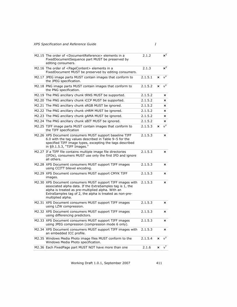
XPS Specification and Reference Guide I
Working Draft 1.0.1, September 2007 411
M2.15 The order of <DocumentReference> elements in a FixedDocumentSequence part MUST be preserved by editing consumers.
2.1.2 ×E
M2.16 The order of <PageContent> elements in a
FixedDocument MUST be preserved by editing consumers.
2.1.3 ×E
M2.17 JPEG image parts MUST contain images that conform to the JPEG specification.
2.1.5.1 × vU
M2.18 PNG image parts MUST contain images that conform to
the PNG specification.
2.1.5.2 × vU
M2.19 The PNG ancillary chunk tRNS MUST be supported. 2.1.5.2 ×
M2.20 The PNG ancillary chunk iCCP MUST be supported. 2.1.5.2 ×
M2.21 The PNG ancillary chunk sRGB MUST be ignored. 2.1.5.2 ×
M2.22 The PNG ancillary chunk cHRM MUST be ignored. 2.1.5.2 ×
M2.23 The PNG ancillary chunk gAMA MUST be ignored. 2.1.5.2 ×
M2.24 The PNG ancillary chunk sBIT MUST be ignored. 2.1.5.2 ×
M2.25 TIFF image parts MUST contain images that conform to the TIFF specification
2.1.5.3 × vU
M2.26 XPS Document consumers MUST support baseline TIFF 6.0 with the tag values described in Table 9–5 for the specified TIFF image types, excepting the tags described in §9.1.5.3, ―TIFF Images.‖
2.1.5.3 ×
M2.27 If a TIFF file contains multiple image file directories (IFDs), consumers MUST use only the first IFD and ignore
all others.
2.1.5.3 ×
M2.28 XPS Document consumers MUST support TIFF images using CCITT bilevel encoding.
2.1.5.3 ×
M2.29 XPS Document consumers MUST support CMYK TIFF
images.
2.1.5.3 ×
M2.30 XPS Document consumers MUST support TIFF images with associated alpha data. If the ExtraSamples tag is 1, the
alpha is treated as pre-multiplied alpha. With an
ExtraSamples tag of 2, the alpha is treated as non-pre-multiplied alpha.
2.1.5.3 ×
M2.31 XPS Document consumers MUST support TIFF images using LZW compression.
2.1.5.3 ×
M2.32 XPS Document consumers MUST support TIFF images using differencing predictors.
2.1.5.3 ×
M2.33 XPS Document consumers MUST support TIFF images
using JPEG compression (compression mode 6 only).
2.1.5.3 ×
M2.34 XPS Document consumers MUST support TIFF images with an embedded ICC profile.
2.1.5.3 ×
M2.35 Windows Media Photo image files MUST conform to the Windows Media Photo specification.
2.1.5.4 × vU
M2.36 Each FixedPage part MUST NOT have more than one 2.1.6 × vT

I Conformance Requirements
412 Working Draft 1.0.1, September 2007
thumbnail part attached. TT
M2.37 Thumbnails MUST be either JPEG or PNG images 2.1.6 × vT
M2.38 If using a fragment in the FontURI attribute of the <Glyphs> element to indicate the font face to use from a TrueType Collection, the attribute value MUST be an integer between 0 and n–1 inclusive, where n is the number of font faces in the TrueType Collection.
2.1.7 × v
M2.39 All fonts used in XPS Documents MUST adhere to the
OpenType font format, which includes TrueTyep and CFF fonts. A subsetted font MUST still be a valid OpenType
font file.
2.1.7.1 × v
M2.40 Producers MUST honor the licensing rights specified in OpenType fonts by following the embedding and obfuscation mechanisms described in this specification.
2.1.7.2 ×
M2.41 Consumers MUST be able to process XPS Documents
using any combination of the embedding and obfuscation mechanisms described in this specification (even if
produced in violation of the production requirements).
2.1.7.2 ×
M2.42 For fonts with ―Restricted license embedding‖ licensing intent, producers MUST NOT embed the font.
2.1.7.2 ×
M2.43 For fonts with ―Print and preview embedding‖ licensing intent, consumers MUST NOT edit or modify any part of the XPS Document markup or hierarchical structure from the FixedDocument containing such a font downwards.
2.1.7.2 ×E
M2.44 For fonts with ―Print and preview embedding‖ licensing intent, producers MUST perform embedded font obfuscation.
2.1.7.2 ×
M2.45 For fonts with ―Print and preview embedding‖ licensing intent, consumers MUST NOT extract or permanently install the font.
2.1.7.2 ×
M2.46 For fonts with ―Editable embedding‖ licensing intent, producers MUST perform embedded font obfuscation.
2.1.7.2 ×
M2.47 For fonts with ―Editable embedding‖ licensing intent,
consumers MUST NOT extract or permanently install the font.
2.1.7.2 ×
M2.48 For fonts with ―No subsetting‖ licensing intent, producers
MUST perform embedded font obfuscation.
2.1.7.2 ×
M2.49 For fonts with ―No subsetting‖ licensing intent, producers MUST NOT subset the font.
2.1.7.2 ×
M2.50 For fonts with ―No subsetting‖ licensing intent, consumers MUST NOT extract or permanently install the font.
2.1.7.2 ×
M2.51 For fonts with ―Bitmap embedding only‖ licensing intent, producers MUST perform embedded font obfuscation for bitmap characters only. If no bitmap characters are present in the font, the producer MUST NOT embed the font.
2.1.7.2 ×
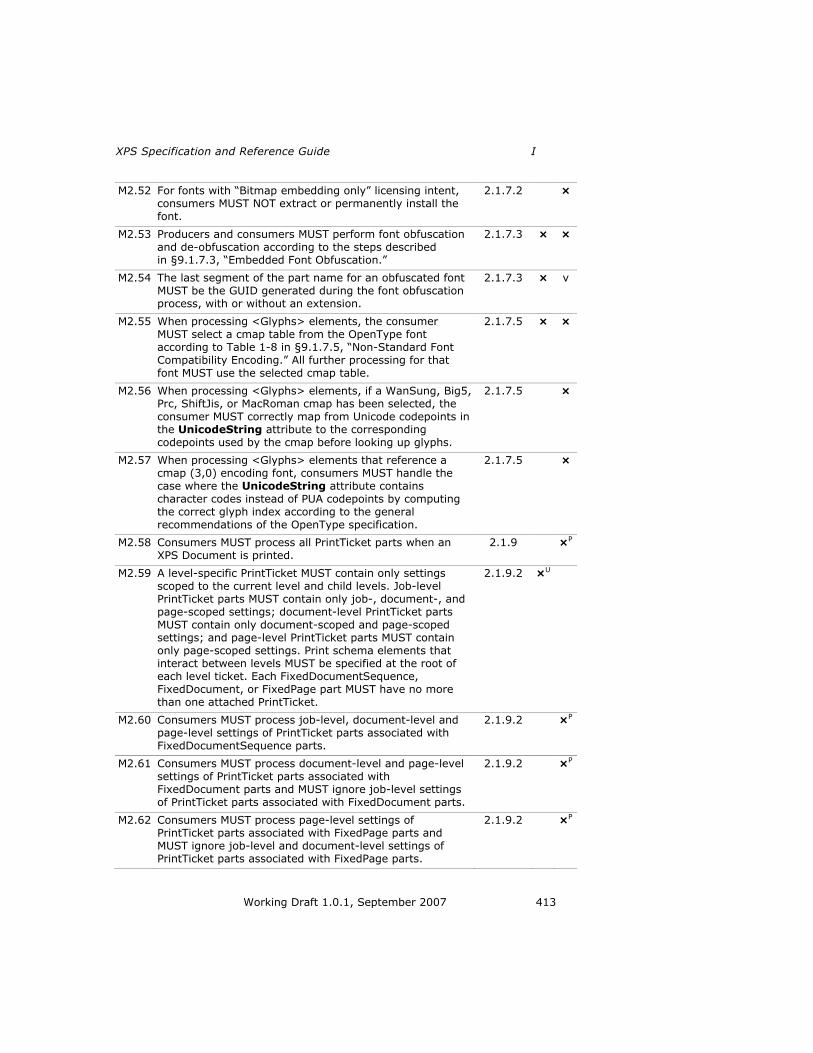
XPS Specification and Reference Guide I
Working Draft 1.0.1, September 2007 413
M2.52 For fonts with ―Bitmap embedding only‖ licensing intent, consumers MUST NOT extract or permanently install the font.
2.1.7.2 ×
M2.53 Producers and consumers MUST perform font obfuscation
and de-obfuscation according to the steps described in §9.1.7.3, ―Embedded Font Obfuscation.‖
2.1.7.3 × ×
M2.54 The last segment of the part name for an obfuscated font MUST be the GUID generated during the font obfuscation process, with or without an extension.
2.1.7.3 × v
M2.55 When processing <Glyphs> elements, the consumer
MUST select a cmap table from the OpenType font according to Table 1-8 in §9.1.7.5, ―Non-Standard Font
Compatibility Encoding.‖ All further processing for that font MUST use the selected cmap table.
2.1.7.5 × ×
M2.56 When processing <Glyphs> elements, if a WanSung, Big5, Prc, ShiftJis, or MacRoman cmap has been selected, the
consumer MUST correctly map from Unicode codepoints in the UnicodeString attribute to the corresponding
codepoints used by the cmap before looking up glyphs.
2.1.7.5 ×
M2.57 When processing <Glyphs> elements that reference a cmap (3,0) encoding font, consumers MUST handle the
case where the UnicodeString attribute contains character codes instead of PUA codepoints by computing the correct glyph index according to the general
recommendations of the OpenType specification.
2.1.7.5 ×
M2.58 Consumers MUST process all PrintTicket parts when an XPS Document is printed.
2.1.9 ×P
M2.59 A level-specific PrintTicket MUST contain only settings scoped to the current level and child levels. Job-level PrintTicket parts MUST contain only job-, document-, and page-scoped settings; document-level PrintTicket parts
MUST contain only document-scoped and page-scoped settings; and page-level PrintTicket parts MUST contain only page-scoped settings. Print schema elements that interact between levels MUST be specified at the root of each level ticket. Each FixedDocumentSequence, FixedDocument, or FixedPage part MUST have no more than one attached PrintTicket.
2.1.9.2 ×U
M2.60 Consumers MUST process job-level, document-level and page-level settings of PrintTicket parts associated with FixedDocumentSequence parts.
2.1.9.2 ×P
M2.61 Consumers MUST process document-level and page-level settings of PrintTicket parts associated with FixedDocument parts and MUST ignore job-level settings of PrintTicket parts associated with FixedDocument parts.
2.1.9.2 ×P
M2.62 Consumers MUST process page-level settings of PrintTicket parts associated with FixedPage parts and MUST ignore job-level and document-level settings of PrintTicket parts associated with FixedPage parts.
2.1.9.2 ×P

I Conformance Requirements
414 Working Draft 1.0.1, September 2007
M2.63 When processing a PrintTicket, consumers MUST first remove all levels of PrintTicket content not applicable to the current element.
2.1.9.3 ×P
M2.64 When processing a PrintTicket, consumers MUST second
validate the PrintTicket according to the methods defined in the PrintTicket Validation Checklist of the Print Schema documentation.
2.1.9.3 ×P
M2.65 Following validation of a PrintTicket, the printing consumer MUST properly interpret the print settings according to the rules for merging two PrintTicket parts.
2.1.9.3 ×P
M2.66 If there is no print setting merge conflict between different PrintTicket levels, a prefix-scoped element MUST
be pushed down, or inherited, from a more general ticket to a more specific ticket. This case is isomorphic to the case where both tickets contain an identical element.
2.1.9.3 ×P
M2.67 If there is a print setting merge conflict between different
PrintTicket levels, the setting from the most specific ticket MUST take precedence.
2.1.9.3 ×P
M2.68 Consumers MUST use semantic document structure
provided in included DocumentStructure and StoryFragments parts in preference to any other analysis
method of generating such structure.
2.1.11 ×
M2.69 Consumers MUST support Markup Compatibility elements and attributes in DocumentStructure, FixedDocument, FixedDocumentSequence, FixedPage, Relationships, Remote Resource Dictionary, SignatureDefinitions, and StoryFragments parts.
Before attempting to validate one of these parts against a schema, consumers MUST remove all Markup
Compatibility elements and attributes, ignorable namespace declarations, and all ignored elements and
attributes not defined in the expected version of XPS
Document markup.
2.3.1 ×
M2.70 XML content MUST be encoded using either UTF-8 or UTF-16. If any such part includes an encoding declaration (as defined in §4.3.3 of the XML specification), that declaration MUST NOT name any encoding other than UTF-8 or UTF-16.
2.3.2 × v
M2.71 DTD content MUST NOT be used in the XML markup defined in this specification, and consumers MUST treat the presence of DTD content as an error.
2.3.2 × ×
M2.72 XML content MUST be valid against the corresponding XSD schema defined in this specification. In particular, the XML content MUST NOT contain elements or attributes drawn from namespaces that are not explicitly defined in the corresponding XSD unless the XSD allows elements or attributes drawn from any namespace to be present in particular locations in the XML markup.
2.3.2 × v

XPS Specification and Reference Guide I
Working Draft 1.0.1, September 2007 415
M2.73 XML content MUST NOT contain elements or attributes drawn from ―xml‖ or ―xsi‖ namespaces unless they are explicitly defined in the XSD schema or by other means in the specification.
2.3.2 × v
M2.74 Properties MUST NOT be set more than once, regardless of the syntax used to specify the value. In certain cases, they can be specified using either property attributes or property elements. Consumers MUST treat properties that are specified in both ways as an error.
2.3.3.2 × v
M2.75 XPS Document markup MUST NOT use the xml:space attribute.
2.3.4 × v
M2.76 The language of the contents of an XPS Document MUST
be identified using the xml:lang attribute, the value of which is inherited by child and descendant elements. When the language of the contents is unknown and is
required, the value ―und‖ (undetermined) MUST be used.
2.3.5.1 ×
M2.77 Producers that generate a relationship MUST include the target part in the XPS Document for any of the following
relationship types: DiscardControl, DocumentStructure, PrintTicket, Required Resource, Restricted Font, StartPart,
StoryFragments, and Thumbnail. Consumers that access the target part of any relationship with one of these
relationship types MUST generate an error if the part is
not included in the XPS Document.
2.1.1 ×U vU
M2.78 Consumers MUST support JPEG images that contain the APP1 marker and interpret the EXIF color space correctly.
2.1.5.1 ×
M2.79 XPS Document consumers MUST support TIFF images that include the EXIF IFD (tag 34665) as described in the EXIF specification. The EXIF color space MUST be interpreted
correctly.
2.1.5.3 ×
Notes: 1
E — Only applies to editing consumers. 2
P — Only applies to printing consumers. 3
T — Only applies if thumbnails are used by the consumer. 4
U — Only required for a producer if the part is generated or for a consumer when 5
accessing the part. 6
Table I–3. Parts and Relationships SHOULD conformance requirements 7
ID Rule
Refe
ren
ce
Pro
du
cer
Co
nsu
mer
S2.1 It is RECOMMENDED that there be exactly one Required
Resource relationship from the FixedPage part for each resource referenced from the markup.
2.1.1 ×

I Conformance Requirements
416 Working Draft 1.0.1, September 2007
S2.2 Each <DocumentReference> element in a FixedDocumentSequence part SHOULD reference a FixedDocument part by relative URI.
2.1.2 ×
S2.3 Each <PageContent> element in a FixedDocument part
SHOULD reference a FixedPage part by relative URI.
2.1.3 ×
S2.4 <ImageBrush> and <Glyphs> elements SHOULD reference Image and Font parts by relative URI.
2.1.4 ×
S2.5 Color profiles embedded in image files SHOULD be used if
present and compatible with this specification.
2.1.5 ×
S2.6 It is RECOMMENDED that JPEG image part names end with the extension ―.jpg‖.
2.1.5.1 ×
S2.7 The use of CMYK JPEG images is NOT RECOMMENDED. TIFF
or Windows Media Photo images SHOULD be used instead to
represent CMYK images.
2.1.5.1 ×
S2.8 It is RECOMMENDED that PNG image part names end with the extension ―.png‖.
2.1.5.2 ×
S2.9 It is RECOMMENDED that TIFF image part names end with
the extension ―.tif‖.
2.1.5.3 ×
S2.10 Consumers SHOULD ignore unsupported TIFF tags (those not described in Table 9–5 and §9.1.5.3, ―TIFF Images‖).
Producers SHOULD NOT include unsupported tags.
2.1.5.3 × ×
S2.11 Given the wide variety of incompliant TIFF images in
circulation, consumers SHOULD test as many different TIFF images as possible, correct common mistakes in TIFF images, and implement a reasonable recovery strategy when a problematic TIFF image is encountered.
2.1.5.3 ×
S2.12 It is RECOMMENDED that Windows Media Photo images end with the extension ―.wdp‖.
2.1.5.4 ×
S2.13 It is RECOMMENDED that if thumbnails are used for pages, a thumbnail SHOULD be included for every page in the
document.
2.1.6 ×
S2.14 Consumers SHOULD only process thumbnails associated via
a package relationship from the package as a whole or via a relationship from a FixedPage part. Thumbnails attached to
any other part SHOULD be ignored.
2.1.6 ×
S2.15 Producers SHOULD use Unicode-encoded fonts. 2.1.7, 2.1.7.5
×
S2.16 For fonts with ―Installable embedding‖ licensing intent, producers SHOULD perform embedded font obfuscation.
2.1.7.2 ×
S2.17 For fonts with ―Installable embedding‖ licensing intent, consumers SHOULD NOT extract or permanently install the font.
2.1.7.2 ×
S2.18 For fonts with ―Restricted license embedding‖ licensing intent, producers SHOULD generate a path filled with an image brush referencing an image of rendered characters and SHOULD include the actual text in the
2.1.7.2 ×

XPS Specification and Reference Guide I
Working Draft 1.0.1, September 2007 417
AutomationProperties.Name attribute of the <Path> element.
S2.19 Although the licensing intent allows embedding of non-obfuscated fonts and installation of the font on a remote
client system under certain conditions, this is NOT RECOMMENDED in XPS Documents. Instead, producers SHOULD always perform font obfuscation, and consumers SHOULD never extract or permanently install fonts.
2.1.7.3 × ×
S2.20 It is RECOMMENDED that the extension of an obfuscated Font part name be ―.odttf‖ for TrueType fonts and ―.odttc‖ for TrueType collections.
2.1.7.3 ×
S2.21 Producers SHOULD include only PrintTicket settings that
support portability of the XPS Document.
2.1.9.1 ×
S2.22 Producers SHOULD only attach PrintTicket parts containing
only document-level and page-level settings with FixedDocument parts.
2.1.9.2 ×
S2.23 Producers SHOULD only attach PrintTicket parts containing
only page-level settings with FixedPage parts.
2.1.9.3 ×
S2.24 The FixedDocumentSequence part SHOULD follow the part name recommendation ―/<FixedDocSeq>.fdseq‖ where
<FixedDocSeq> is the name of the FixedDocumentSequence. The FixedDocumentSequence
SHOULD use the extension ―.fdseq‖.
2.2 ×
S2.25 A FixedDocument part SHOULD follow the part name recommendation ―/Documents/<n>/<FixedDocument>.fdoc‖ where <n> is a numeral that indicates the ordinal position of the fixed document in the fixed document sequence and <FixedDocument> is the name of the fixed document. FixedDocument parts SHOULD use the extension ―.fdoc‖.
2.2 ×
S2.26 A FixedPage part SHOULD follow the part name recommendation ―/Documents/<n>/Pages/<m>.fpage‖ where <n> represents the document that includes this page
and <m> is the page number. FixedPage parts SHOULD use the extension ―.fpage‖.
2.2 ×
S2.27 A resource that is specific to a particular document SHOULD follow the part name recommendation ―/Documents/<n>/Resources/<Resource>‖ where <n> is the document that uses the resource and <Resource> is the segments identifying the particular resource.
A resource that is shared across multiple documents SHOULD follow the part name recommendation ―/Resources/<Resource>‖.
A Font resource SHOULD use ―Fonts/<FontName>.<FontExt>‖ for its <Resource> value, where <FontExt> SHOULD be either ―.ttf‖ or ―.odttf‖ for non-obfuscated and obfuscated fonts respectively.
An Image resource SHOULD use ―Images/<ImageName>.<ImageExt>‖ for its <Resource>
2.2 ×

I Conformance Requirements
418 Working Draft 1.0.1, September 2007
value, where <ImageExt> is the correct extension for the image type.
A Remote Resource Dictionary resource SHOULD use ―Dictionaries/<DictName>.dict‖ for its <Resource> value. A Remote Resource Dictionary SHOULD use ―.dict‖ as its extension.
<FontName>, <ImageName>, and <DictName> SHOULD be a string representation of a GUID value if the resource is a shared resource.
S2.28 A DocumentStructure part SHOULD follow the part name recommendation ―/Documents/<n>/Structure/<DocStruct>.struct‖ where <n> is the fixed document that the document structure applies to. DocumentStructure parts SHOULD use the extension ―.struct‖.
2.2 ×
S2.29 A StoryFragments part SHOULD follow the part name
recommendation ―/Documents/<n>/Structure/Fragments/<m>.frag‖ where
<n> is the fixed document that contains the story fragments and <m> is the page number the StoryFragments part applies to. StoryFragments parts SHOULD use the extension ―.frag‖.
2.2 ×
S2.30 ICC profile parts SHOULD follow the part name recommendation
―/Documents/<n>/Metadata/<ProfileName>.<ProfileExt>‖ where <n> is the fixed document that contains the profile.
ICC profile parts shared across multiple documents SHOULD follow the part name recommendation
―/Metadata/<ProfileName>.<ProfileExt>‖. In this case, <ProfileName> SHOULD be a string representation of a
GUID value.
The <ProfileExt> SHOULD be appropriate to the color profile type, such as ―.icm‖.
2.2 ×
S2.31 Thumbnail parts SHOULD follow the part name
recommendation ―/Documents/<n>/Metadata/<ThumbName>.<ThumbExt>‖
where <n> is the fixed document that contains the profile.
If the Thumbnail part represents the package as a whole, it SHOULD follow the part name recommendation ―/Metadata/<ThumbName>.<ThumbExt>‖. In this case, <ThumbName> SHOULD be a string representation of a GUID value.
The <ThumbExt> SHOULD be appropriate to the image type, either ―.png‖ or ―.jpg‖.
2.2 ×
S2.32 PrintTicket part names associated with the entire job SHOULD be associated via relationship with the FixedDocumentSequence part and follow the part name recommendation ―/Metadata/<PrintTicketName>.xml‖.
PrintTicket parts associated with a particular fixed document
2.2 ×

XPS Specification and Reference Guide I
Working Draft 1.0.1, September 2007 419
or fixed page SHOULD follow the part name recommendation ―/Documents/<n>/Metadata/<PrintTicketName>.xml‖, where <n> is the fixed document that uses these parts.
PrintTicket parts SHOULD use the extension ―.xml‖.
S2.33 The names of any non-standard parts that are associated with a particular fixed document SHOULD follow the part name recommendation ―/Documents/<n>/Other/<PartName>‖, where <n> is the fixed document to which the part belongs.
2.2 ×
S2.34 Consumers SHOULD support JPEG images that contain APP0, APP2, APP13, and APP14 markers.
2.1.5.1 ×
Table I–4. Parts and Relationships OPTIONAL conformance requirements 1
ID Rule
Refe
ren
ce
Pro
du
cer
Co
nsu
mer
O2.1 Thumbnail parts MAY be included in an XPS Document 2.1 ×
O2.2 PrintTicket parts MAY be included in an XPS Document. 2.1 ×
O2.3 ICC Profile parts MAY be included in an XPS Document. 2.1 ×
O2.4 DocumentStructure parts MAY be included in an XPS Document.
2.1 ×
O2.5 StoryFragments parts MAY be included in an XPS Document. 2.1 ×
O2.6 SignatureDefinitions parts MAY be included in an XPS Document.
2.1 ×
O2.7 DiscardControl parts MAY be included in an XPS Document. 2.1 ×
O2.8 A Core Properties relationship MAY be included in an XPS
Document, from the package to the Core Properties part.
2.1.1 ×
O2.9 A Digital Signatures Origin relationship MAY be included in an XPS Document, from the package to the Digital Signature
Origin part.
2.1.1 ×
O2.10 Digital Signature relationships MAY be included in an XPS
Document, from the Digital Signature Origin part to a Digital Signature XML Signature part.
2.1.1 ×
O2.11 Digital Signature Certificate relationships MAY be included in
an XPS Document, from a Digital Signature XML Signature part to the Digital Signature Certificate part.
2.1.1 ×
O2.12 Digital Signature Definitions parts MAY be included in an XPS Document, from a FixedDocument part to the Digital Signature Definitions part.
2.1.1 ×
O2.13 DiscardControl relationships MAY be included in an XPS Document, from the package to a DiscardControl part.
2.1.1 ×
O2.14 DocumentStructure relationships MAY be included in an XPS Document, from a FixedDocument part to the DocumentStructure part.
2.1.1 ×

I Conformance Requirements
420 Working Draft 1.0.1, September 2007
O2.15 PrintTicket relationships MAY be included in an XPS Document, from a FixedDocumentSequence, FixedDocument, or FixedPage part to a PrintTicket part.
2.1.1 ×
O2.16 StoryFragments relationships MAY be included in an XPS
Document, from a FixedPage part to a StoryFragments part.
2.1.1 ×
O2.17 Thumbnail relationships MAY be included in an XPS Document, from the package to an Image part or from a FixedPage part to an Image part.
2.1.1 ×
O2.18 Color Profiles MAY be embedded in image files. 2.1.5 ×
O2.19 Thumbnail images MAY be attached to a FixedPage part using a Thumbnail relationship.
2.1.6 ×
O2.20 Fonts MAY be subsetted based on glyph usage. 2.1.7.1 ×
O2.21 Producers MAY use a 128-bit random number instead of a
true GUID for an obfuscated font name.
2.1.7.3 ×
O2.22 An obfuscated Font part MAY have an arbitrary extension. 2.1.7.3 ×
O2.23 Producers MAY add digital signature requests and instructions to an XPS Document in the form of signature definitions.
2.1.10 ×
O2.24 A producer MAY sign against an existing signature definition to provide additional signature information.
2.1.10 ×
O2.25 A recipient of an XPS Document MAY also sign it against a signature definition.
2.1.10 ×
O2.27 Consumers MAY provide an algorithmic construction of the structure of an XPS Document based on a page-layout
analysis, provided such structure is not explicitly provided in DocumentStructure and StoryFragments parts.
2.1.11 ×
O2.28 A resource that is intended to be used across multiple fixed
documents MAY be named according to the guidelines for shared resources.
2.2 ×
O2.29 Producers MAY include Markup Compatibility elements and
attributes in DocumentStructure, FixedDocument,
FixedDocumentSequence, FixedPage, Relationships, Remote Resource Dictionary, SignatureDefinitions, and
StoryFragments parts.
2.3.1 ×
O2.30 Wherever a single whitespace character is allowed in XPS Document markup, multiple whitespace characters MAY be used (unless explicitly restricted by a pattern restriction in the corresponding schema).
2.3.4 ×
O2.31 Attributes in XPS Document markup that specify comma-delimited attribute values MAY, unless specified otherwise, OPTIONALLY include whitespace characters preceding or following the comma.
2.3.4 ×
O2.32 Where the XPS Document schema specifies attributes of types that allow whitespace collapsing, leading and trailing whitespace in the attribute value MAY be used along with other whitespace that relies on the whitespace collapsing
2.3.4 ×

XPS Specification and Reference Guide I
Working Draft 1.0.1, September 2007 421
behavior specified in the XML Schema Specification.
I.3 Documents 1
Table I–5. Document MUST conformance requirements 2
ID Rule
Refe
ren
ce
Pro
du
cer
Co
nsu
mer
M3.1 The order of <DocumentReference> elements MUST match the order of the documents in the fixed document sequence.
3.1 ×
M3.2 The Source attribute of the <DocumentReference> element
MUST specify a FixedDocument part within the XPS Document.
3.1.1 × v
M3.3 Producers MUST NOT produce a document with multiple
<DocumentReference> elements that reference the same
fixed document.
3.1.1 × v
M3.4 The order of <PageContent> elements MUST match the order of the pages in the document.
3.2 ×
M3.5 The Source attribute of the <PageContent> element MUST
specify a FixedPage part within the XPS Document.
3.2.1 × v
M3.6 Producers MUST NOT produce markup where a <PageContent> element references the same fixed page referenced by any other <PageContent> element in the entire XPS Document, even in other fixed documents within
the fixed payload.
3.2.1 × v
M3.7 If the attribute is specified, the BleedBox BleedOriginX value MUST be less than or equal to 0000.
3.3.1 × vF
M3.8 If the attribute is specified, the BleedBox BleedOriginY value MUST be less than or equal to 0.
3.3.1 × vF
M3.9 If the attribute is specified, the BleedBox BleedWidth value
MUST be greater than or equal to the Width attribute value plus the absolute value of the BleedBox BleedOriginX value.
3.3.1 × vF
M3.10 If the attribute is specified, the BleedBox BleedHeight value
MUST be greater than or equal to the fixed page Height value plus the absolute value of the BleedBox BleedOriginY value.
3.3.1 × vF
M3.11 If the attribute is specified, the ContentBox ContentOriginX
value MUST be greater than or equal to 0 and less than the fixed page Width attribute value
3.3.2 × vF
M3.12 If the attribute is specified, the ContentBox ContentOriginY value MUST be greater than or equal to 0 and less than the fixed page Height attribute value.
3.3.2 × vF
M3.13 If the attribute is specified, the ContentBox ContentWidth value MUST be less than or equal to the difference between
3.3.2 × vF

I Conformance Requirements
422 Working Draft 1.0.1, September 2007
the fixed page Width attribute value and the ContentBox ContentOriginX value.
M3.14 If the attribute is specified, the ContentBox ContentHeight value MUST be less than or equal to the difference between
the fixed page Height attribute value and the ContentBox ContentOriginY value.
3.3.2 × vF
M3.15 When rendering a fixed page for printing, consumers MUST be aware of the interaction between the fixed page markup and the PrintTicket settings.
3.3.4 × vP
M3.16 When the PrintTicket specifies the page scaling option
FitApplicationBleedSizeToPageImageableSize, printing consumers MUST scale the bleed box (producer bleed size)
to the PageImageableSize, preserving the aspect ratio.
3.3.4.1 ×P
M3.17 When the PrintTicket specifies the page scaling option
FitApplicationContentSizeToPageImageableSize, printing consumers MUST scale the content box (producer content
size) to the PageImageableSize, preserving the aspect ratio.
3.3.4.2 ×P
M3.18 When the PrintTicket specifies the page scaling option FitApplicationMediaSizeToPageImageableSize, printing
consumers MUST scale the height and width (producer media size) to the PageImageableSize, preserving the
aspect ratio.
3.3.4.3 ×P
M3.19 When the PrintTicket specifies the page scaling option FitApplicationMediaSizeToPageMediaSize, printing consumers MUST scale the height and width (producer media size) to the PageMediaSize, preserving the aspect ratio.
3.3.4.4 ×P
M3.20 The x:Key attribute of the <Canvas> element MUST be present when the element is defined in a resource dictionary. It MUST NOT be specified outside a resource dictionary.
3.4 × v
Notes: 1
F — Only necessary if the referenced feature is used. 2
P Only applies to printing consumers. 3
Table I–6. Document SHOULD conformance requirements 4
ID Rule
Refe
ren
ce
Pro
du
cer
Co
nsu
mer
S3.1 Specifying a ContentBox attribute for the <FixedPage> element is RECOMMENDED.
3.3 ×
S3.2 Invalid bleed box specifications SHOULD be ignored in favor of the default bleed box.
3.3.1 ×
S3.3 Invalid content box specifications SHOULD NOT be rendered and SHOULD generate an error.
3.3.1 ×

XPS Specification and Reference Guide I
Working Draft 1.0.1, September 2007 423
S3.4 In the absence of media scaling, the fixed page content is imaged directly to the physical media with the origin of the fixed page aligned with the origin of the physical media size. Any fixed page content that extends beyond the dimension of the physical media size SHOULD be clipped.
3.3.4 ×P
Notes: 1
P — Only applies to printing consumers. 2
I.4 Graphics 3
Table I–7. Graphics MUST conformance requirements 4
ID Rule
Refe
ren
ce
Pro
du
cer
Co
nsu
mer
M4.1 The x:Key attribute of the <Path> element MUST be present when the element is defined in a resource dictionary. It MUST NOT be specified outside a resource dictionary.
4.1 × v
M4.2 The x:Key attribute of the <PathGeometry> element MUST be present when the element is defined in a resource dictionary. It MUST NOT be specified outside a resource dictionary.
4.2.1.1 × v
M4.3 A <PathGeometry> element contains a set of path figures specified either with the Figures attribute or with a child <PathFigure> element. Producers MUST NOT specify the path
figures of a geometry with both the Figures attribute and a child <PathFigure> element.
4.2.1.1 × v
Table I–8. Graphics SHOULD conformance requirements 5
ID Rule
Refe
ren
ce
Pro
du
cer
Co
nsu
mer
S4.1 Line segments and curve segments SHOULD NOT be specified as zero-length.
4.2.2.1 ×
Table I–9. Graphics OPTIONAL conformance requirements 6
ID Rule
Refe
ren
ce
Pro
du
cer
Co
nsu
mer
O4.1 Consumers or viewers that perform anti-aliasing MAY ―snap‖ those control points of the path that are situated on the path
bounding box to whole device pixels if the ignorable
4.1 ×

I Conformance Requirements
424 Working Draft 1.0.1, September 2007
SnapsToDevicePixels attribute is specified as true.
I.5 Text 1
Table I–10. Text MUST conformance requirements 2
ID Rule
Refe
ren
ce
Pro
du
cer
Co
nsu
mer
M5.1 If the CaretStops attribute is missing from the <Glyphs>
element, a consumer MUST interpret the text as having a caret stop between each Unicode UTF-16 code unit and at
the beginning and end of the text.
5.1 ×S
M5.2 If the UnicodeString attribute of the <Glyphs> element specifies an empty string (―‖ or ―{}‖) and the Indices
attribute is not specified or is empty, the consumer MUST generate an error.
5.1 × v
M5.3 The x:Key attribute of the <Glyphs> element MUST be present when the element is defined in a resource dictionary. It MUST NOT be specified outside a resource dictionary.
5.1 × v
M5.4 The sum of the code unit counts for all the GlyphMapping entries in the Indices attribute MUST NOT exceed the number of UTF-16 code units in the UnicodeString attribute if the UnicodeString attribute is specified and
does not contain an empty value (―‖ or ―{}‖). If a ClusterMapping is not specified within a GlyphMapping entry,
the code unit count is 1. If the Indices attribute specifies a GlyphIndex that does not exist in the font, the consumer
MUST generate an error.
5.1.3 × v
M5.5 If there is not a one-to-one mapping between code units in the UnicodeString attribute and the glyph indices, the
GlyphIndex value in the Indices attribute MUST be specified.
5.1.3 ×
M5.6 The AdvanceWidth of the Indices attribute MUST be calculated as the exact unrounded origin of the subsequent
glyph minus the sum of the calculated (that is, rounded) advance widths of the preceding glyphs.
5.1.3 ×
M5.7 A UnicodeString attribute value that begins with an open brace (―{‖) MUST be escaped with a prefix of ―{}‖. If a UnicodeString attribute value starts with ―{}‖, consumers MUST ignore those first two characters in processing the UnicodeString and in calculating index positions for the characters of the UnicodeString.
5.1.4 × ×
M5.9 If the UnicodeString attribute contains a Unicode code unit that cannot be mapped to a glyph index via a cmap table in the font and there is no corresponding GlyphIndex entry in
5.1.4 × ×

XPS Specification and Reference Guide I
Working Draft 1.0.1, September 2007 425
the Indices attribute, the consumer MUST display the .notdef glyph
M5.10 In the absence of entries in the Indices attribute to override the Unicode code units in the UnicodeString attribute
value, consumers MUST treat Unicode control marks in the UnicodeString attribute like ordinary characters and render the glyphs to which the Unicode control marks are mapped in the CMAP table.
5.1.4 ×
M5.11 Because advance-widths, glyph indices, and caret-stops are associated with the generated Unicode string, consumers MUST NOT normalize the UnicodeString attribute value to
produce an internal representation.
5.1.4 ×
M5.12 Producers MUST lay out algorithmically emboldened glyphs using advance widths that are 2% of the em size larger than when not algorithmically emboldened.
5.1.5 ×
M5.13 Consumers MUST implement the effect of algorithmic
emboldening such that the black box of the glyph grows by 2% of the em size. When advance widths are omitted from
the markup and the glyphs are algorithmically emboldened, the advance widths obtained from the horizontal metrics
font table (if IsSideways is false) or the vertical metrics font table (if IsSideways is true) of the font MUST be
increased by 2% of the em size.
5.1.5 ×
M5.14 Producers MUST lay out algorithmically italicized glyphs
using exactly the same advance widths as when not algorithmically italicized.
5.1.5 ×
M5.15 Producers MUST NOT specify text that is both right-to-left (BidiLevel attribute value of 1) and vertical (IsSideways attribute set to true).
5.1.6.2 × v
M5.16 If a consumer does not understand the specified device font name, it MUST render the embedded version of the font.
5.1.7 ×P
M5.17 When rendering a printer device font, consumers MUST use
the UnicodeString attribute and ignore the glyph index components of the Indices attribute.
5.1.7 ×P
M5.18 When rendering a printer device font, consumers MUST still honor the advance width and x,y offset values present in the Indices attribute.
5.1.7 ×P
M5.19 For producers, a <Glyphs> element with a specified device
font name MUST have exactly one Indices glyph per character in the UnicodeString attribute. Its Indices
attribute MUST NOT include any cluster specifications. If the Indices attribute includes a cluster mapping, the consumer MUST NOT use the device font name and MUST render the embedded version of the font.
5.1.7 × vFP
M5.20 For producers of a <Glyphs> element with a specified device font name, each of the Indices glyphs MUST include a
specified advance width and MUST include specified x and y offset values if they are non-zero.
5.1.7 ×

I Conformance Requirements
426 Working Draft 1.0.1, September 2007
M5.22 If there are insufficient flags in the CaretStops attribute value to correspond to all the UTF-16 code units in the UnicodeString attribute value, all remaining UTF-16 code units in the Unicode string MUST be considered valid caret stops.
5.1.9 ×S
M5.23 If the Indices attribute is specified, the values provided MUST be used in preference to values determined from the UnicodeString attribute alone.
12.1.3 ×
Notes: 1
F — Only necessary if the referenced feature is used. 2
P — Only applies to printing consumers. 3
S — Only applies to consumers that implement selection. 4
Table I–11. Text SHOULD conformance requirements 5
ID Rule
Refe
ren
ce
Pro
du
cer
Co
nsu
mer
S5.1 The value of the CaretStops attribute SHOULD indicate that the
caret cannot stop in front of most combining marks and the second UTF-16 code unit of UTF-16 surrogate pairs.
5.1 ×
S5.2 If producers include control marks in the Unicode string, they SHOULD include an Indices attribute to specify glyph indices and/or character-to-glyph mapping information for the control marks.
5.1.4 ×
S5.3 If alternate vertical character representations are available in the font, the producer SHOULD use those in preference to the IsSideways attribute and provide their glyph indices in the Indices attribute.
5.1.6 ×
S5.4 Producers SHOULD NOT produce markup that will result in
different rendering between consumers using the embedded font to render and consumers using the device font to render.
5.1.7 ×
S5.5 Specifying a UnicodeString for <Glyphs> elements is RECOMMENDED, as it supports searching, selection, and accessibility.
5.1.4 ×
Table I–12. Text OPTIONAL conformance requirements 6
ID Rule
Refe
ren
ce
Pro
du
cer
Co
nsu
mer
O5.1 Producers MAY include Unicode control marks in the Unicode
string. Such marks include control codes, layout controls, invisible operators, deprecated format characters, variation
selectors, non-characters, and specials, according to their
5.1.4 ×

XPS Specification and Reference Guide I
Working Draft 1.0.1, September 2007 427
definition within the Unicode specification.
O5.2 Producers MAY choose to generate UnicodeString attribute values that are not normalized by any Unicode-defined algorithm.
5.1.4 ×
O5.3 Consumers that understand the device font name MAY ignore the embedded font and use the device-resident version.
5.1.7 ×P
O5.4 Glyph indices MAY be omitted from markup where there is a
one-to-one mapping between the positions of Unicode scalar values in the UnicodeString attribute and the positions of
glyphs in the glyph string and the glyph index is the value in selected character mapping table of the font.
5.1.10.1 ×
O5.5 Glyph advance widths MAY be omitted from markup where the advance width desired is specified in the font tables,
once adjusted for algorithmic emboldening.
5.1.10.2 ×
O5.6 Glyph horizontal and vertical offsets MAY be omitted from markup where the offset is 0.0.
5.1.10.2 ×
Notes: 1
P — Only applies to printing consumers. 2
I.6 Brushes 3
Table I–13. Brushes MUST conformance requirements 4
ID Rule
Refe
ren
ce
Pro
du
cer
Co
nsu
mer
M6.1 The x:Key attribute of the <SolidColorBrush> element MUST be present when the element is defined in a resource dictionary. It
MUST NOT be specified outside a resource dictionary.
6.1 × v
M6.2 The x:Key attribute of the <ImageBrush> element MUST be present when the element is defined in a resource dictionary. It
MUST NOT be specified outside a resource dictionary.
6.2 × v
M6.3 An <ImageBrush> element MUST reference a JPEG, PNG, TIFF 6.0, or Windows Media Photo Image part within the XPS Document package.
6.2 × v
M6.4 The x:Key attribute of the <VisualBrush> element MUST be present when the element is defined in a resource dictionary. It MUST NOT be specified outside a resource dictionary.
6.3 × v
M6.5 The x:Key attribute of the <LinearGradientBrush> element MUST be present when the element is defined in a resource dictionary. It MUST NOT be specified outside a resource dictionary.
6.5 × v
M6.6 The x:Key attribute of the <RadialGradientBrush> element MUST be present when the element is defined in a resource dictionary. It MUST NOT be specified outside a resource dictionary.
6.6 × v

I Conformance Requirements
428 Working Draft 1.0.1, September 2007
I.7 Common Properties 1
Table I–14. Common properties MUST conformance requirements 2
ID Rule
Refe
ren
ce
Pro
du
cer
Co
nsu
mer
M7.1 Individual resource values MUST be specified within a resource dictionary.
7.2 ×
M7.2 Namespace prefixes in resource definitions MUST apply in the context of the definition, rather than in the context of the resource reference.
7.2.3 × ×
M7.3 An xml:lang attribute within a resource definition MUST be interpreted in the context of the resource reference, not the resource definition.
7.2.3 × ×
M7.4 A remote resource dictionary MUST follow the requirements that apply to inline resource dictionaries.
7.2.3.1 × v
M7.5 A remote resource dictionary MUST NOT contain any resource definition children that reference another remote
resource dictionary.
7.2.3.1 × v
M7.6 A <ResourceDictionary> element that specifies a remote resource dictionary in its Source attribute MUST NOT
contain any resource definition children.
7.2.3.1 × v
M7.7 Inline references to fonts or images in remote resource dictionary entries MUST be interpreted with the same base
URI as the Remote Resource Dictionary part, not from the base URI of the part referring to the particular remote
resource dictionary entry.
7.2.3.1 × ×
M7.8 When a resource definition references a previously defined
resource with the same name in an ancestor resource dictionary, the reference MUST be resolved before the
redefined resource is added to the dictionary
7.2.5 × ×
M7.9 If a resource definition references another resource, the reference MUST be resolved in the context of the resource
definition, not in the context of the resource use.
7.2.5 × ×
M7.10 If a resource dictionary contains Markup Compatibility elements and attributes, the processing of the Markup Compatibility markup MUST occur in the context of the definition of the resource dictionary, not in the context of resource references.
7.2.6 × ×
M7.11 The x:Key attribute of the <MatrixTransform> element MUST be present when the element is defined in a resource dictionary. It MUST NOT be specified outside a resource dictionary.
7.4.1 × v
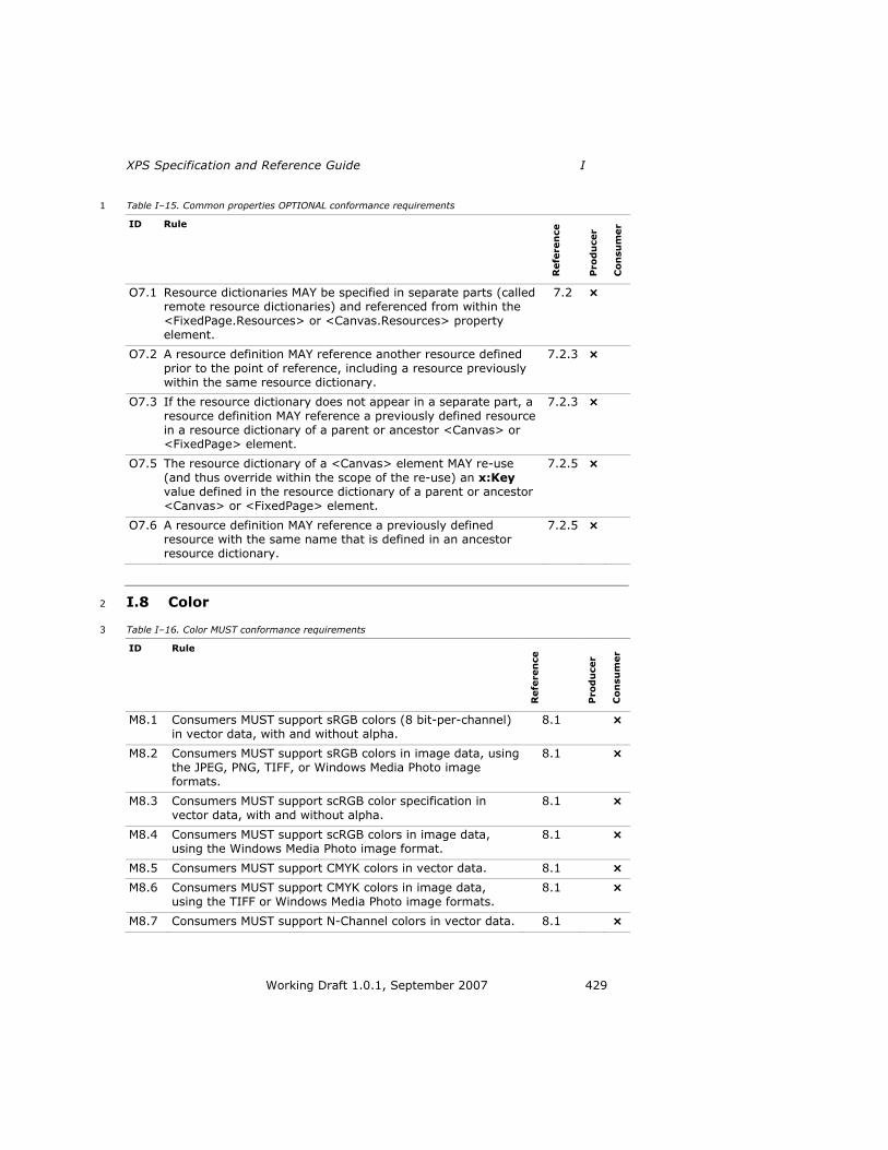
XPS Specification and Reference Guide I
Working Draft 1.0.1, September 2007 429
Table I–15. Common properties OPTIONAL conformance requirements 1
ID Rule
Refe
ren
ce
Pro
du
cer
Co
nsu
mer
O7.1 Resource dictionaries MAY be specified in separate parts (called remote resource dictionaries) and referenced from within the
<FixedPage.Resources> or <Canvas.Resources> property element.
7.2 ×
O7.2 A resource definition MAY reference another resource defined prior to the point of reference, including a resource previously within the same resource dictionary.
7.2.3 ×
O7.3 If the resource dictionary does not appear in a separate part, a
resource definition MAY reference a previously defined resource
in a resource dictionary of a parent or ancestor <Canvas> or <FixedPage> element.
7.2.3 ×
O7.5 The resource dictionary of a <Canvas> element MAY re-use
(and thus override within the scope of the re-use) an x:Key value defined in the resource dictionary of a parent or ancestor
<Canvas> or <FixedPage> element.
7.2.5 ×
O7.6 A resource definition MAY reference a previously defined resource with the same name that is defined in an ancestor
resource dictionary.
7.2.5 ×
I.8 Color 2
Table I–16. Color MUST conformance requirements 3
ID Rule
Refe
ren
ce
Pro
du
cer
Co
nsu
mer
M8.1 Consumers MUST support sRGB colors (8 bit-per-channel)
in vector data, with and without alpha.
8.1 ×
M8.2 Consumers MUST support sRGB colors in image data, using the JPEG, PNG, TIFF, or Windows Media Photo image formats.
8.1 ×
M8.3 Consumers MUST support scRGB color specification in
vector data, with and without alpha.
8.1 ×
M8.4 Consumers MUST support scRGB colors in image data, using the Windows Media Photo image format.
8.1 ×
M8.5 Consumers MUST support CMYK colors in vector data. 8.1 ×
M8.6 Consumers MUST support CMYK colors in image data,
using the TIFF or Windows Media Photo image formats.
8.1 ×
M8.7 Consumers MUST support N-Channel colors in vector data. 8.1 ×
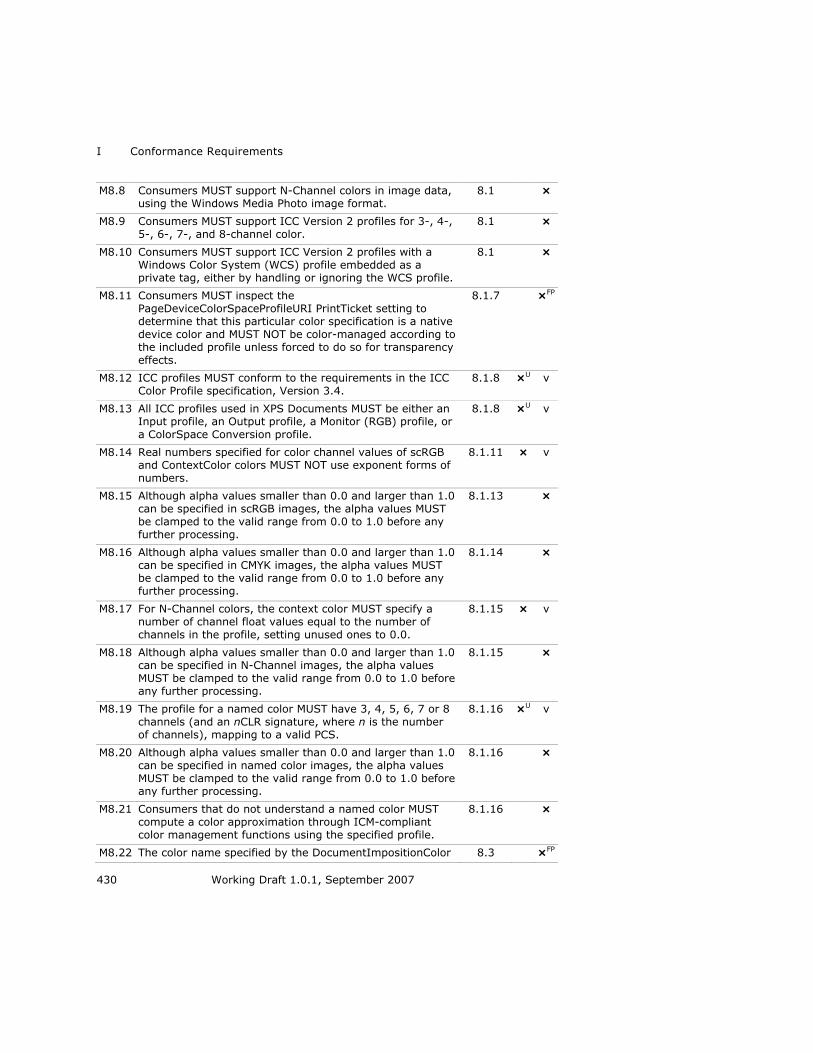
I Conformance Requirements
430 Working Draft 1.0.1, September 2007
M8.8 Consumers MUST support N-Channel colors in image data, using the Windows Media Photo image format.
8.1 ×
M8.9 Consumers MUST support ICC Version 2 profiles for 3-, 4-, 5-, 6-, 7-, and 8-channel color.
8.1 ×
M8.10 Consumers MUST support ICC Version 2 profiles with a Windows Color System (WCS) profile embedded as a private tag, either by handling or ignoring the WCS profile.
8.1 ×
M8.11 Consumers MUST inspect the
PageDeviceColorSpaceProfileURI PrintTicket setting to determine that this particular color specification is a native
device color and MUST NOT be color-managed according to the included profile unless forced to do so for transparency
effects.
8.1.7 ×FP
M8.12 ICC profiles MUST conform to the requirements in the ICC
Color Profile specification, Version 3.4.
8.1.8 ×U v
M8.13 All ICC profiles used in XPS Documents MUST be either an Input profile, an Output profile, a Monitor (RGB) profile, or
a ColorSpace Conversion profile.
8.1.8 ×U v
M8.14 Real numbers specified for color channel values of scRGB and ContextColor colors MUST NOT use exponent forms of
numbers.
8.1.11 × v
M8.15 Although alpha values smaller than 0.0 and larger than 1.0 can be specified in scRGB images, the alpha values MUST be clamped to the valid range from 0.0 to 1.0 before any further processing.
8.1.13 ×
M8.16 Although alpha values smaller than 0.0 and larger than 1.0 can be specified in CMYK images, the alpha values MUST be clamped to the valid range from 0.0 to 1.0 before any further processing.
8.1.14 ×
M8.17 For N-Channel colors, the context color MUST specify a number of channel float values equal to the number of
channels in the profile, setting unused ones to 0.0.
8.1.15 × v
M8.18 Although alpha values smaller than 0.0 and larger than 1.0 can be specified in N-Channel images, the alpha values
MUST be clamped to the valid range from 0.0 to 1.0 before any further processing.
8.1.15 ×
M8.19 The profile for a named color MUST have 3, 4, 5, 6, 7 or 8
channels (and an nCLR signature, where n is the number of channels), mapping to a valid PCS.
8.1.16 ×U v
M8.20 Although alpha values smaller than 0.0 and larger than 1.0
can be specified in named color images, the alpha values
MUST be clamped to the valid range from 0.0 to 1.0 before any further processing.
8.1.16 ×
M8.21 Consumers that do not understand a named color MUST
compute a color approximation through ICM-compliant color management functions using the specified profile.
8.1.16 ×
M8.22 The color name specified by the DocumentImpositionColor 8.3 ×FP
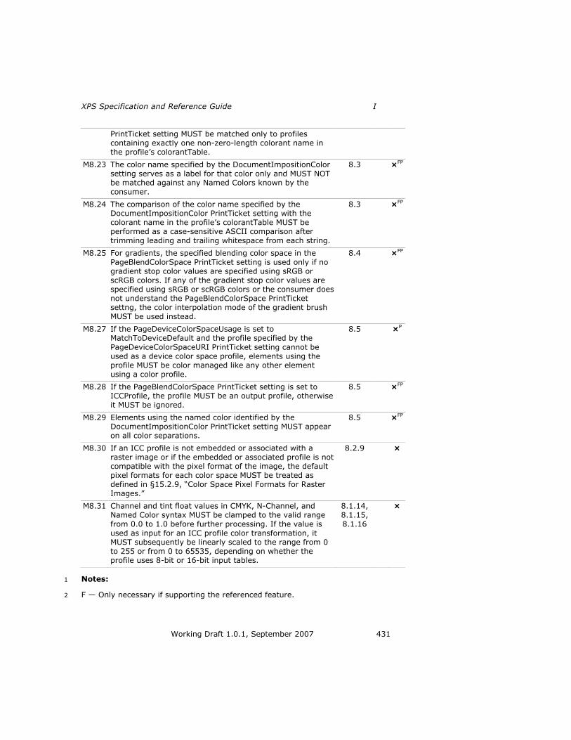
XPS Specification and Reference Guide I
Working Draft 1.0.1, September 2007 431
PrintTicket setting MUST be matched only to profiles containing exactly one non-zero-length colorant name in the profile‘s colorantTable.
M8.23 The color name specified by the DocumentImpositionColor
setting serves as a label for that color only and MUST NOT be matched against any Named Colors known by the consumer.
8.3 ×FP
M8.24 The comparison of the color name specified by the DocumentImpositionColor PrintTicket setting with the colorant name in the profile‘s colorantTable MUST be performed as a case-sensitive ASCII comparison after
trimming leading and trailing whitespace from each string.
8.3 ×FP
M8.25 For gradients, the specified blending color space in the PageBlendColorSpace PrintTicket setting is used only if no gradient stop color values are specified using sRGB or
scRGB colors. If any of the gradient stop color values are specified using sRGB or scRGB colors or the consumer does
not understand the PageBlendColorSpace PrintTicket settng, the color interpolation mode of the gradient brush
MUST be used instead.
8.4 ×FP
M8.27 If the PageDeviceColorSpaceUsage is set to MatchToDeviceDefault and the profile specified by the
PageDeviceColorSpaceURI PrintTicket setting cannot be
used as a device color space profile, elements using the profile MUST be color managed like any other element
using a color profile.
8.5 ×P
M8.28 If the PageBlendColorSpace PrintTicket setting is set to ICCProfile, the profile MUST be an output profile, otherwise
it MUST be ignored.
8.5 ×FP
M8.29 Elements using the named color identified by the DocumentImpositionColor PrintTicket setting MUST appear
on all color separations.
8.5 ×FP
M8.30 If an ICC profile is not embedded or associated with a raster image or if the embedded or associated profile is not compatible with the pixel format of the image, the default pixel formats for each color space MUST be treated as defined in §15.2.9, ―Color Space Pixel Formats for Raster Images.‖
8.2.9 ×
M8.31 Channel and tint float values in CMYK, N-Channel, and Named Color syntax MUST be clamped to the valid range from 0.0 to 1.0 before further processing. If the value is
used as input for an ICC profile color transformation, it MUST subsequently be linearly scaled to the range from 0
to 255 or from 0 to 65535, depending on whether the profile uses 8-bit or 16-bit input tables.
8.1.14, 8.1.15, 8.1.16
×
Notes: 1
F — Only necessary if supporting the referenced feature. 2

I Conformance Requirements
432 Working Draft 1.0.1, September 2007
P — Only applies to printing consumers. 1
U — Only required for a producer if the part is generated or for a consumer when 2
accessing the part. 3
Table I–17. Color SHOULD conformance requirements 4
ID Rule
Refe
ren
ce
Pro
du
cer
Co
nsu
mer
S8.1 ICC profiles SHOULD be used when embedded in any image format with any color space. Images with integer pixel formats are assumed to have sRGB as the default color space and images with floating point pixel formats are
assumed to have scRGB as the default color space; in these cases, an ICC profile is unnecessary.
8.1.8 ×
S8.2 If consistency of appearance is important, instead of attaching or embedding a gray ICC profile, the producer
SHOULD adjust the gray tone response curve of a grayscale image before adding it to the XPS Document.
8.1.8 ×
S8.3 A producer of XPS documents containing named colors
SHOULD create the color profile in such a way that a linear ramp of the channel values corresponding to a named
colorant maps to PCS values resulting in the same color appearance for consumers unaware of named colors (or the
specific colorant).
8.1.16 ×
S8.4 The ContextColor syntax requires a minimum of 1 Alpha value and 3 Channel values for named colors. It is RECOMMENDED that a 1 or 2 tone profile uses the first 1 or
2 channels, respectively, and specifies 0 for the remaining channels.
8.1.16 ×
S8.5 If the consumer does not know ALL of the colorants named in the clrt tag, it SHOULD treat the profile as if it were a regular N-channel source profile and SHOULD NOT attempt
to use any of the known colorants, as that would result in undefined results.
8.1.16 ×
S8.6 Support for JPEG CMYK images varies by implementation and SHOULD NOT be used in XPS Documents.
8.2.4.3 ×
S8.7 For consumers that do perform separation, the imposition
named color is an indicator that the tint level supplied SHOULD be used for all device colorants.
8.3 ×P
S8.8 Producers SHOULD create the profile used by the imposition color in such a way that it does not lay down excessive ink
when printed on a device that does not perform separation.
8.3 ×P
S8.9 If a consumer understands the PageBlendColorSpace PrintTicket setting, it SHOULD convert all color to the specified blending color space before performing a blend operation.
8.4 ×P

XPS Specification and Reference Guide I
Working Draft 1.0.1, September 2007 433
S8.10 If the PageDeviceColorSpaceUsage PrintTicket setting is set to MatchToDeviceDefault, the device‘s internal color profile SHOULD be used for color management of all elements not using the profile specified by the PageDeviceColorSpaceProfileURI PrintTicket setting.
8.5 ×P
S8.11 If the PageDeviceColorSpaceUsage PrintTicket setting is set to OverrideDeviceDefault and the profile specified by the PageDeviceColorSpaceProfileURI PrintTicet setting has a number of channels matching the number of primaries of the device, it SHOULD be used instead of the device‘s internal color management for all elements.
8.5 ×P
S8.12 If the PageBlendColorSpace PrintTicket setting is set to ICCProfile, the Uri property of the option specifies an ICC
profile defining the color space that SHOULD be used for
blending.
8.5 ×P
S8.13 The PageICMRenderingIntent PrintTicket setting SHOULD be ignored for elements using a profile that specifies the
rendering intent in the profile.
8.5 ×P
S8.14 A consumer incapable of supporting named colors SHOULD treat the colorant table for named colors tag in an ICC profile
as a user-defined custom tag, and therefore ignore it. The consumer SHOULD instead use the color tables as provided
in the profile to convert the specified colors to the Profile
Connection Space (PCS).
8.1.8 ×
Notes: 1
P — Only applies to printing consumers. 2
Table I–18. Color OPTIONAL conformance requirements 3
ID Rule
Refe
ren
ce
Pro
du
cer
Co
nsu
mer
O8.1 Consumers are not required to handle all color spaces natively, but rather MAY convert data specified in a rich color space to sRGB at an early stage (possibly resulting in reduced fidelity).
8.1 ×
O8.2 An ICC profile MAY contain the private tag, ―MS00‖, which specifies an embedded Windows Color System (WCS) profile.
8.1.8 × ×
O8.3 When a named color is used in a gradient brush or with transparency, the result produced by consumers that are not
named-color aware MAY differ significantly from the result produced by consumers that are named-color aware.
8.1.16 ×
O8.4 A named color profile MAY be used with images for spot coloring.
8.1.16 × ×
O8.5 Consumers MAY perform color separation, if desired. 8.3 ×
O8.6 Consumers MAY support rich color spaces such as scRGB or CMYK. Consumers that encounter any document using non-sRGB colors MAY process those colors using the simpler sRGB
8.4 ×

I Conformance Requirements
434 Working Draft 1.0.1, September 2007
color space, resulting in deviations, especially for alpha blending
O8.7 If the PageColorManagement PrintTicket setting specifies a value of Driver, the driver MAY color manage elements or
convert them to different color spaces.
8.5 ×P
O8.8 Elements using the profile specified by PageBlendColorSpace PrintTicket setting with a value of ICCProfile MAY be blended naively (channel-by-channel) without converting through PCS.
8.5 ×P
Notes: 1
P — Only applies to printing consumers. 2
I.9 Document Structure and Interactivity 3
Table I–19. Document structure MUST conformance requirements 4
ID Rule
Refe
ren
ce
Pro
du
cer
Co
nsu
mer
M9.1 In order to merge the table cells and rows correctly, producers
MUST specify empty <TableCellStructure> elements for cells that do not break across story fragments.
9.1.2 ×D
M9.2 If hyperlinked <Path> or <Glyphs> elements are rendered as
overlapping on the page, consumers MUST treat the topmost element as the only hyperlink that may be activated in the
overlapping region.
9.2.1 ×H
M9.3 If a producer specifies a FixedPage.NavigateUri attribute on a <Canvas> element, consumers MUST treat all child elements of that canvas that do not override this value with their own FixedPage.NavigateUri attribute setting as having an associated hyperlink.
9.2.1 ×H
M9.4 Relative internal hyperlinks between FixedPage parts MUST specify, at a minimum, the named address relative to the FixedDocument part.
9.2.1 ×H v H
M9.5 In order to be addressable by either a hyperlink or the document outline, the named address MUST appear in the
<PageContent.LinkTargets> element in the fixed document.
9.2.1 ×H
M9.6 If a named address appears in the <PageContent.LinkTargets> element in the fixed document but is not found in the Name attribute of an element within the associated fixed page, consumers MUST treat the top of
the associated fixed page as the named address.
9.2.1 ×H
M9.7 If a named address in a URI fragment is not found, consumers MUST ignore the fragment portion of the URI.
9.2.1 ×H
M9.8 Internal references MUST specify a page address relative to the fixed document sequence.
9.2.2 ×H v H
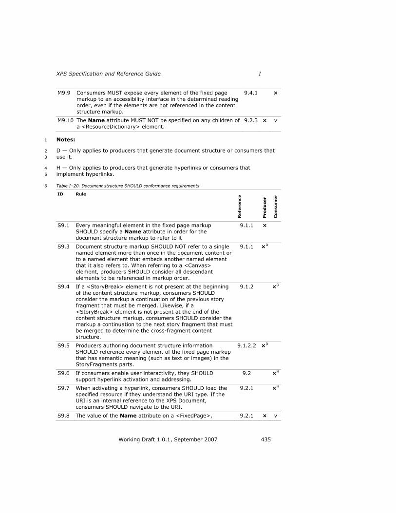
XPS Specification and Reference Guide I
Working Draft 1.0.1, September 2007 435
M9.9 Consumers MUST expose every element of the fixed page markup to an accessibility interface in the determined reading order, even if the elements are not referenced in the content structure markup.
9.4.1 ×
M9.10 The Name attribute MUST NOT be specified on any children of a <ResourceDictionary> element.
9.2.3 × v
Notes: 1
D — Only applies to producers that generate document structure or consumers that 2
use it. 3
H — Only applies to producers that generate hyperlinks or consumers that 4
implement hyperlinks. 5
Table I–20. Document structure SHOULD conformance requirements 6
ID Rule
Refe
ren
ce
Pro
du
cer
Co
nsu
mer
S9.1 Every meaningful element in the fixed page markup
SHOULD specify a Name attribute in order for the document structure markup to refer to it
9.1.1 ×
S9.3 Document structure markup SHOULD NOT refer to a single
named element more than once in the document content or
to a named element that embeds another named element that it also refers to. When referring to a <Canvas>
element, producers SHOULD consider all descendant elements to be referenced in markup order.
9.1.1 ×D
S9.4 If a <StoryBreak> element is not present at the beginning
of the content structure markup, consumers SHOULD consider the markup a continuation of the previous story
fragment that must be merged. Likewise, if a <StoryBreak> element is not present at the end of the content structure markup, consumers SHOULD consider the markup a continuation to the next story fragment that must be merged to determine the cross-fragment content structure.
9.1.2 ×D
S9.5 Producers authoring document structure information SHOULD reference every element of the fixed page markup that has semantic meaning (such as text or images) in the StoryFragments parts.
9.1.2.2 ×D
S9.6 If consumers enable user interactivity, they SHOULD support hyperlink activation and addressing.
9.2 ×H
S9.7 When activating a hyperlink, consumers SHOULD load the specified resource if they understand the URI type. If the URI is an internal reference to the XPS Document, consumers SHOULD navigate to the URI.
9.2.1 ×H
S9.8 The value of the Name attribute on a <FixedPage>, 9.2.1 × v

I Conformance Requirements
436 Working Draft 1.0.1, September 2007
<Canvas>, <Path>, or <Glyphs> element SHOULD be unique within the scope of the fixed document.
S9.9 It is RECOMMENDED that Name attribute values on <FixedPage>, <Canvas>, <Path>, and <Glyphs> elements
be unique within an entire fixed document sequence.
9.2.1 × v
S9.10 If the Name attribute is specified, producers SHOULD also create a corresponding <LinkTarget> element in the FixedDocument part within the <PageContent> element that links to the parent fixed page
9.2.3 ×
S9.11 A hyperlink destination in the same fixed document
SHOULD be expressed as a relative URI.
9.2.4 ×H
S9.12 If selection is supported, consumers SHOULD provide a visual cue over or around selected elements.
9.3 ×S
S9.13 Selection order within an XPS Document SHOULD follow reading order.
9.3 ×S
S9.14 In the absence of document structure provided in the XPS
Document, consumers SHOULD, at minimum, rely on the markup order to determine reading order.
9.4.1 ×
S9.15 Producers SHOULD order the markup in FixedPage parts to
reflect the order in which it is intended to be read.
9.4.1 ×
S9.16 When document structure information is present, consumers SHOULD rely on the order of appearance of
named elements in the content structure markup to determine reading order.
9.4.1 ×
S9.17 The RECOMMENDED reading order of a page-centric application is 1) order the content by page, 2) order by story fragment within the page based on the order the <StoryFragment> elements are specified in the StoryFragments part for that page, 3) order by <NamedElement> reference within the <StoryFragment> element, 4) append all un-referenced elements that appear
in the fixed page markup, ordered by markup order.
9.4.1 ×
S9.18 Producers SHOULD order <StoryFragment> elements in each StoryFragments part in their intended reading order.
9.4.1 ×D
S9.19 The RECOMMENDED reading order of a story-centric
application is as follows: 1) Order content by story in the sequence the <Story> elements appear in the
DocumentStructure part. 2) Within a story, order <StoryFragmentReference> elements in the sequence they
appear in the DocumentStructure part. 3) Within a story fragment, order by <NamedElement> references in the StoryFragments part markup. 4) Append all un-referenced
elements that appear in the fixed page markup, ordered by page number, then markup order
9.4.1 ×D
S9.20 Producers SHOULD order <Story> elements in the DocumentStructure part in their intended reading order.
9.4.1 ×D
S9.21 Producers SHOULD order <StoryFragmentReference> 9.4.1 ×D

XPS Specification and Reference Guide I
Working Draft 1.0.1, September 2007 437
elements within a <Story> element in their intended reading order.
S9.22 A screen reader consumer SHOULD read the document according to its reading order.
9.4.2 ×
S9.23 A screen reader SHOULD use the UnicodeString attribute of each <Glyphs> element to determine the text to read.
9.4.2 ×
S9.24 If a screen reader provides features to navigate the document by structural elements, such as paragraphs or
table rows, it SHOULD use any document structure information included in the XPS Document.
9.4.2 ×D
S9.25 If the screen reader provides features to describe images, it SHOULD read the text provided in the AutomationProperties.Name and AutomationProperties.HelpText attributes.
9.4.2 ×
S9.26 If the screen reader provides features to describe hyperlink
addresses, it SHOULD read the text provided in the FixedPage.NavigateUri attribute.
9.4.2 ×
S9.27 Images and graphics SHOULD specify text alternatives for
images and graphics to make this content accessible to vision-impaired individuals. The
AutomationProperties.Name attribute SHOULD contain a short description of the basic contents of the image or
vector graphic. Individual <Path> elements that do not provide any semantic meaning (such as a line between sections or outlining a table) SHOULD NOT specify these text alternative attributes.
9.4.3 ×
S9.28 An image SHOULD specify the AutomationProperties.Name and AutomationProperties.HelpText attributes on the <Path> element that is filled with an <ImageBrush> that describes the content specified by the ImageSource
attribute of the <ImageBrush> element.
9.4.3 ×
S9.29 A vector graphic (a collection of one or more <Path> elements representing a single drawing) SHOULD specify
the AutomationProperties.Name and AutomationProperties.HelpText attributes only once, directly on a <Canvas> element wrapping the <Path> elements comprising the graphic.
9.4.3 ×
S9.30 Children of <VisualBrush> elements SHOULD NOT be referenced by document structure markup.
9.1.2.13 ×D
Notes: 1
D — Only applies to producers that generate document structure or consumers that 2
use it. 3
H — Only applies to producers that generate hyperlinks or consumers that 4
implement hyperlinks. 5
S — Only applies to consumers that implement selection. 6

I Conformance Requirements
438 Working Draft 1.0.1, September 2007
Table I–21. Document structure OPTIONAL conformance requirements 1
ID Rule
Refe
ren
ce
Pro
du
cer
Co
nsu
mer
O9.1 Producers MAY choose to add document structure information to XPS Documents. Consumers MAY ignore any
authored document structure or hyperlinks.
Clause 9
×D ×D
O9.2 Producers MAY provide either the document outline or the document content, or both; consumers MAY ignore either or both.
9.1 ×D
O9.3 Consumers MAY choose to interpret document structure markup that refers to a single named element more than
once, or refers to a named element that embeds another
named element that is also referenced, as duplicate content.
9.1.1 ×D
O9.4 Consumers MAY first attempt to locate named elements for
document structure directly from the FixedDocument part markup, where they might appear as <LinkTarget>
elements if that named element is also intended as an addressable location.
9.1.1 ×D
O9.5 A <TableStructure> element is the complete definition of a
table. An implementation MAY use it to build special functionality, such as row or column selection.
9.1.2.6 ×D
O9.6 Internal hyperlinks can specify a named element fragment relative to a particular fixed document, but consumers MAY interpret such a URI relative to the entire fixed document sequence instead
9.2.1 ×H
O9.7 Consumers MAY ignore the Name attribute. 9.2.3 ×
O9.8 Consumers MAY ignore the FixedPage.NavigateUri attribute.
9.2.4 ×
O9.9 Viewing consumers that support interactivity MAY support
selection and copying.
9.3 ×S
O9.10 Consumers MAY use the FragmentType attribute of the <StoryFragment> element to determine selection behavior, such as disallowing selection of both the page header and the page contents while allowing independent selection within those stories.
9.3 ×DS
O9.11 In the absence of document structure information provided in the XPS Document, consumers MAY infer the reading
order from the position of elements on the page.
9.4.1 ×
O9.12 Consumers MAY use the FragmentType attribute of the <StoryFragment> element to determine reading order by interpreting elements that have FragmentType values of
Header and Footer as belonging first or last in the reading order, respectively.
9.4.1 ×D

XPS Specification and Reference Guide I
Working Draft 1.0.1, September 2007 439
O9.13 Screen readers MAY inspect the Indices attribute to resolve potential ambiguities in the UnicodeString attribute.
9.4.2 ×
Notes: 1
D — Only applies to producers that generate document structure or consumers that 2
use it. 3
H — Only applies to producers that generate hyperlinks or consumers that 4
implement hyperlinks. 5
S — Only applies to consumers that implement selection. 6
I.10 XPS Document Package Features 7
Table I–22. XPS Document package feature MUST conformance requirements 8
ID Rule
Refe
ren
ce
Pro
du
cer
Co
nsu
mer
M10.1 Consumers MUST be prepared to correctly process
interleaved packages in which the PrintTicket or the portion of the relationship data attaching the PrintTicket
appears in the package after the affected part.
10.1 ×P
M10.2 Consumers MUST be able to consume packages regardless of their interleaving structure.
10.1.3 ×
M10.3 Consumers that lack the resources to process a part
MUST indicate an error condition.
10.1.3 ×
M10.4 When consuming interleaved packages, consumers
MUST NOT discard any parts without instruction from a DiscardControl part unless they have the ability to
access the parts again.
10.1.3 ×
M10.5 If a consumer encounters a reference to an unknown part, it MUST continue to receive further bytes of the
package until the unknown part has been transmitted or until the end of the package is reached (indicating an
error condition).
10.1.3 ×
M10.6 The DiscardControl part MUST NOT reference itself. 10.1.4.1 × v
M10.7 If either the Target attribute or the SentinelPage attribute of the <Discard> element contain an invalid reference (refer outside the package), the <Discard> element MUST be ignored.
10.1.4.1.2 ×
M10.8 All producers and consumers signing and verifying signatures for end users or applications MUST adhere to the XPS Document signature policy, and producers and consumers MUST interpret digital signatures consistently.
10.2.1 ×A ×A
M10.9 Consumers MUST NOT disable functionality based on 10.2.1 ×A

I Conformance Requirements
440 Working Draft 1.0.1, September 2007
whether or not an action will invalidate a signature.
M10.10 An XPS Document MUST be considered signed according to the XPS Document signing policy, regardless of the validity of that signature, if the signing rules described
in §10.2.1.1, ―Signing Rules‖ are observed.
10.2.1.1 ×A
M10.11 An XPS Document MUST NOT be considered signed according to the XPS Document signing policy if any part not covered by the signing rules is included in the signature or if any relationship not covered by the signing rules is included in the signature.
10.2.1.1 ×A
M10.12 An XPS Document digital signer MUST NOT sign an XPS Document that contains content (parts or relationships
parts) to be signed that defines the Markup Compatibility namespace but the signer does not fully understand all elements, attributes, and alternate
content representations introduced through the markup compatibility mechanisms.
10.2.1.1 ×A
M10.13 An XPS Document digital signature MUST be shown as
an incompliant digital signature if it violates any of the signing rules regarding parts or relationships that MUST
or MUST NOT be signed.
10.2.1.2 ×A
M10.14 An XPS Document digital signature MUST be shown as a broken digital signature if it is not an incompliant digital signature, but the signature fails the signature
validation routines described in the Open Packaging Conventions.
10.2.1.2 ×A
M10.15 An XPS Document digital signature MUST be shown as a questionable digital signature if it is not an incompliant or broken digital signature, but the certificate cannot be
authenticated against the certificate authority or the signed content (parts and relationships) contain
elements or attributes from an unknown namespace introduced through Markup Compatibility mechanisms.
10.2.1.2 ×A
M10.16 An XPS Document digital signature MUST be shown as a valid digital signature if it is not an incompliant, broken, or questionable digital signature.
10.2.1.2 ×A
M10.17 To prohibit additional signatures in an XPS Document, the signing application MUST sign all the Digital Signature Origin part‘s relationships of relationship type Digital Signature with the same signature as the rest of the content.
10.2.1.3 ×A
M10.18 XPS Document signatures MUST NOT refer to a remote certificate store. All certificates MUST be stored in the XPS Document either as a Certificate part or in the Digital Signature XML Signature part.
10.2.1.4 ×A vA
M10.19 To link a <SignatureDefinition> to a signature, the value of the SpotID MUST be specified in the Id attribute of the corresponding <Signature> element in
10.2.2.2.1 ×A

XPS Specification and Reference Guide I
Working Draft 1.0.1, September 2007 441
the Digital Signature XML Signature part.
M10.20 Due to space and rendering limitations, producers MUST NOT assume that consumers will use the values specified in the <SpotLocation> element.
10.2.2.3 ×A
M10.21 Consumers MUST display the full value of the <Intent> element to the signing party, either in the signature spot or through some other mechanism.
10.2.2.4 ×A
M10.22 If specified, the <SignBy> date and time MUST be
specified as a complete date plus hours, minutes, and seconds in UTC time, as described in the W3C Note
―Date and Time Formats.‖
10.2.2.5 ×A
M10.23 There MUST NOT be more than one DiscardControl package relationship.
10.1.4.1 ×R vR
M10.24 In some cases, producers might rewrite the contents of a package so that parts are provided more than once,
allowing consumers to discard a part in order to free resources for additional processing. Each instance of a
part MUST be stored as a new, uniquely named part in the package.
10.1.4.1 ×R vR
Notes: 1
A — Only applies to producers or consumers implementing digital signature features. 2
P — Only applies to printing consumers. 3
R — Only applies to producers or consumers that use DiscardControl parts. 4
Table I–23. XPS Document package feature SHOULD conformance requirements 5
ID Rule
Refe
ren
ce
Pro
du
cer
Co
nsu
mer
S10.1 When interleaving, the Content Types stream SHOULD be interleaved according to the recommendations in the
OPC specification.
10.1 ×
S10.2 When interleaving, PrintTicket parts SHOULD be written to the package before the part to which they are
attached.
10.1 ×
S10.3 When interleaving, the portion of the relationship data attaching the PrintTicket to a part SHOULD be written to
the package before the part to which it is attached or in close proximity to the part to which it is attached.
10.1 ×
S10.4 When interleaving, if no PrintTicket settings are specified for a FixedDocumentSequence,
FixedDocument, or FixedPage part, an empty PrintTicket part SHOULD be attached to the part, and the portion of
the relationship data attaching the empty PrintTicket SHOULD be written to the package before the part to
which it is attached or in close proximity to the part to
10.1 ×
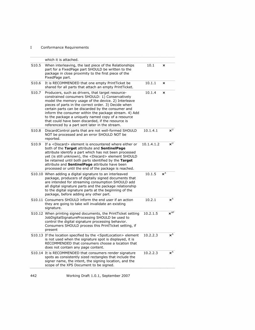
I Conformance Requirements
442 Working Draft 1.0.1, September 2007
which it is attached.
S10.5 When interleaving, the last piece of the Relationships part for a FixedPage part SHOULD be written to the package in close proximity to the first piece of the
FixedPage part.
10.1 ×
S10.6 It is RECOMMENDED that one empty PrintTicket be shared for all parts that attach an empty PrintTicket.
10.1.1 ×
S10.7 Producers, such as drivers, that target resource-
constrained consumers SHOULD: 1) Conservatively model the memory usage of the device. 2) Interleave
pieces of parts in the correct order. 3) Decide when certain parts can be discarded by the consumer and
inform the consumer within the package stream. 4) Add to the package a uniquely named copy of a resource that could have been discarded, if the resource is
referenced by a part sent later in the stream.
10.1.4 ×
S10.8 DiscardControl parts that are not well-formed SHOULD NOT be processed and an error SHOULD NOT be
reported.
10.1.4.1 ×U
S10.9 If a <Discard> element is encountered where either or both of the Target attribute and SentinelPage
attribute identify a part which has not been processed yet (is still unknown), the <Discard> element SHOULD be retained until both parts identified by the Target
attribute and SentinelPage attribute have been processed or until the end of the package is reached.
10.1.4.1.2 ×U
S10.10 When adding a digital signature to an interleaved package, producers of digitally signed documents that are intended for streaming consumption SHOULD add
all digital signature parts and the package relationship to the digital signature parts at the beginning of the
package, before adding any other part.
10.1.5 ×A
S10.11 Consumers SHOULD inform the end user if an action they are going to take will invalidate an existing signature.
10.2.1 ×A
S10.12 When printing signed documents, the PrintTicket setting JobDigitalSignatureProcessing SHOULD be used to control the digital signature processing behavior. Consumers SHOULD process this PrintTicket setting, if present
10.2.1.5 ×AP
S10.13 If the location specified by the <SpotLocation> element is not used when the signature spot is displayed, it is RECOMMENDED that consumers choose a location that does not contain any page content.
10.2.2.3 ×A
S10.14 It is RECOMMENDED that consumers render signature spots as consistently sized rectangles that include the signer name, the intent, the signing location, and the scope of the XPS Document to be signed.
10.2.2.3 ×A

XPS Specification and Reference Guide I
Working Draft 1.0.1, September 2007 443
S10.15 It is RECOMMENDED that a signature spot be a clickable area used to launch the digital signing process.
10.2.2.3 ×A
S10.16 If the <SignBy> element is specified, the consumer SHOULD NOT allow the signing party to sign the
document using this particular signature spot after the date and time specified.
10.2.2.5 ×A
S10.17 The values specified in the Core Properties part SHOULD refer to the entire fixed payload, including the root FixedDocumentSequence part and the compilation of all FixedDocument parts it references.
10.3 ×C
S10.18 Head-first XPS Document consumers SHOULD attempt to detect inconsistent packages as soon as possible and
SHOULD generate an error message, even if they have already processed the pages that resulted in the error.
10.1 ×K
S10.19 The viewing consumer SHOULD use the values specified in the <SpotLocation> element to place a signature
spot.
10.2.2.3 ×F
Notes: 1
A — Only applies to producers or consumers implementing digital signature features. 2
C — Only applies if Core Properties are used. 3
F — Only necessary if supporting the referenced feature. 4
K — Only applies to consumers that consume the XPS Document package head-first. 5
P — Only applies to printing consumers. 6
U — Only required for a producer if the part is generated or for a consumer when 7
accessing the part. 8
Table I–24. XPS Document package feature OPTIONAL conformance requirements 9
ID Rule
Refe
ren
ce
Pro
du
cer
Co
nsu
mer
O10.1 Interleaving is OPTIONAL. 10.1 ×
O10.2 Producers MAY optimize the interleaving order of parts
to help consumers avoid stalls during read-time streaming, and to allow consumers to manage their
memory resources more efficiently.
10.1.2 ×
O10.3 Consumers MAY discard FixedPage parts once they have been processed.
10.1.3 ×
O10.4 Consumers MAY discard FixedDocument and
FixedDocumentSequence parts after all their child elements and their closing tags have been processed.
10.1.3 ×
O10.5 In the absence of explicit directives to the contrary, consumers MAY discard parts as directed by the
10.1.3 ×

I Conformance Requirements
444 Working Draft 1.0.1, September 2007
DiscardControl part.
O10.6 Some producers (typically drivers) MAY choose a suitable interleaving order by modeling the resource management behavior of the consumer.
10.1.4 ×
O10.7 A consumer MAY decide to ignore a malformed DiscardControl part in its entirety or from the first malformed node onward.
10.1.4.1 ×
O10.8 An XPS Document digital signer MAY choose not to sign
any content (parts or relationships parts) that defines the Markup Compatibility namespace, even if the
content is fully understood.
10.2.1.1 ×A
O10.9 An XPS Document digital signature MAY be shown as a questionable digital signature if it is not an incompliant or broken digital signature, but contains some other
detectable problem at the discretion of the consumer.
10.2.1.2 ×A
O10.10 XPS Documents MAY be signed more than once. 10.2.1.3 ×A
O10.11 Producers MAY include the JobDigitalSignatureProcessing setting in the job-level
PrintTicket within the XPS Document content.
10.2.1.5 ×A
O10.12 The SpotID attribute of the <SignatureDefinition> element MAY be used to link to an existing signature.
10.2.2.2.1 ×A
O10.13 Consumers MAY choose a size and shape to display a
signature spot based on the desired display information and page content.
10.2.2.3 ×A
O10.14 The <SigningLocation> element MAY be set by the original producer of the XPS Document or by the signing party at the time of signing.
10.2.2.6 ×A
Notes: 1
A — Only applies to producers or consumers implementing digital signature features. 2
I.11 Rendering Rules 3
Table I–25. Rendering rules MUST conformance requirements 4
ID Rule
Refe
ren
ce
Pro
du
cer
Co
nsu
mer
M11.1 Producers MUST generate XPS Documents that can be
accurately rendered by following the rules described in the ―Rendering Rules‖ clause. Consumers MUST adhere to the
rules described in the ―Rendering Rules‖ clause when rendering XPS Documents
Clause
11
× ×
M11.2 If a non-invertible transform is encountered during rendering, consumers MUST omit rendering the affected
11.1.3 ×
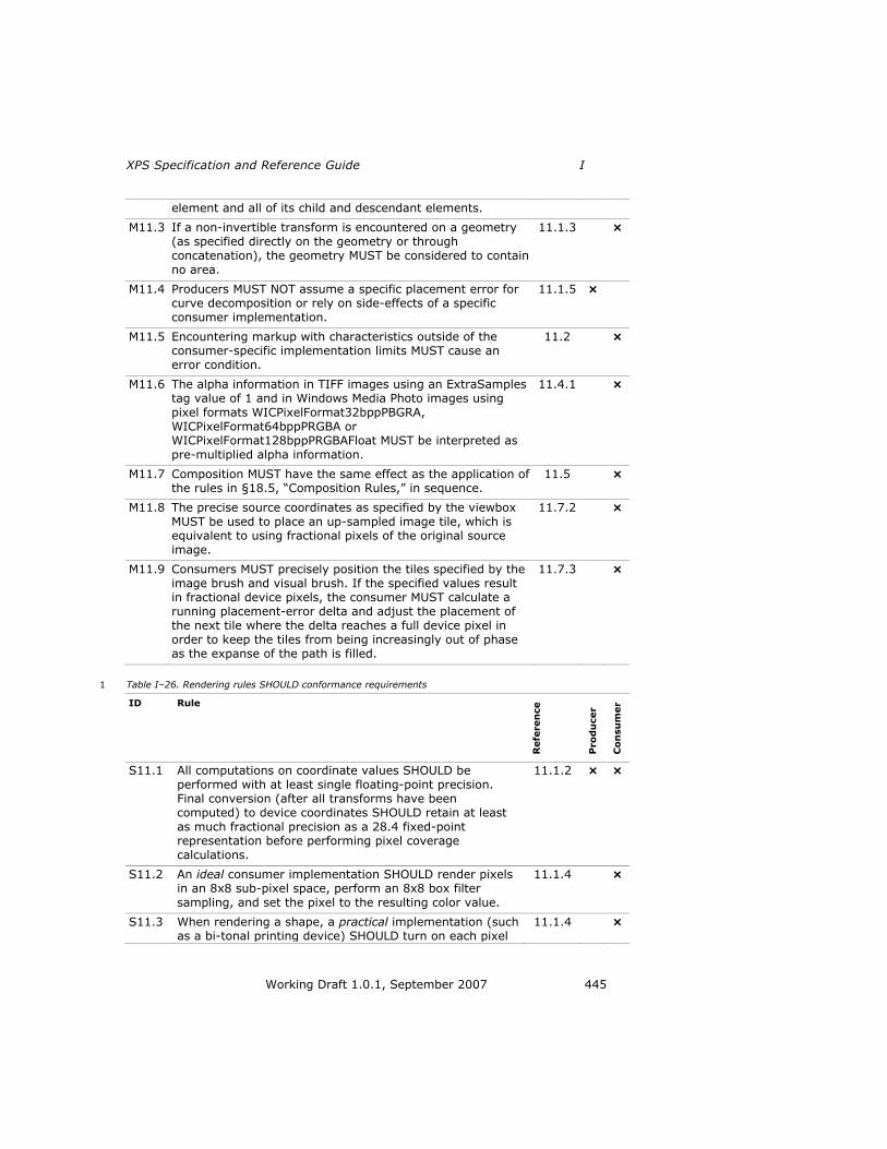
XPS Specification and Reference Guide I
Working Draft 1.0.1, September 2007 445
element and all of its child and descendant elements.
M11.3 If a non-invertible transform is encountered on a geometry (as specified directly on the geometry or through concatenation), the geometry MUST be considered to contain
no area.
11.1.3 ×
M11.4 Producers MUST NOT assume a specific placement error for curve decomposition or rely on side-effects of a specific consumer implementation.
11.1.5 ×
M11.5 Encountering markup with characteristics outside of the consumer-specific implementation limits MUST cause an
error condition.
11.2 ×
M11.6 The alpha information in TIFF images using an ExtraSamples tag value of 1 and in Windows Media Photo images using pixel formats WICPixelFormat32bppPBGRA,
WICPixelFormat64bppPRGBA or WICPixelFormat128bppPRGBAFloat MUST be interpreted as
pre-multiplied alpha information.
11.4.1 ×
M11.7 Composition MUST have the same effect as the application of the rules in §18.5, ―Composition Rules,‖ in sequence.
11.5 ×
M11.8 The precise source coordinates as specified by the viewbox
MUST be used to place an up-sampled image tile, which is equivalent to using fractional pixels of the original source
image.
11.7.2 ×
M11.9 Consumers MUST precisely position the tiles specified by the image brush and visual brush. If the specified values result in fractional device pixels, the consumer MUST calculate a running placement-error delta and adjust the placement of the next tile where the delta reaches a full device pixel in order to keep the tiles from being increasingly out of phase as the expanse of the path is filled.
11.7.3 ×
Table I–26. Rendering rules SHOULD conformance requirements 1
ID Rule
Refe
ren
ce
Pro
du
cer
Co
nsu
mer
S11.1 All computations on coordinate values SHOULD be performed with at least single floating-point precision. Final conversion (after all transforms have been computed) to device coordinates SHOULD retain at least as much fractional precision as a 28.4 fixed-point representation before performing pixel coverage calculations.
11.1.2 × ×
S11.2 An ideal consumer implementation SHOULD render pixels in an 8x8 sub-pixel space, perform an 8x8 box filter sampling, and set the pixel to the resulting color value.
11.1.4 ×
S11.3 When rendering a shape, a practical implementation (such as a bi-tonal printing device) SHOULD turn on each pixel
11.1.4 ×

I Conformance Requirements
446 Working Draft 1.0.1, September 2007
whose center (at x+0.5) is covered by the shape, or is touched by the shape with the shape extending beyond the pixel center in the positive x or y direction of the device.
S11.4 When rendering geometries, consumers SHOULD render curves so they appear smooth from a normal viewing distance.
11.1.5 ×
S11.5 When no anti-aliasing is used, abutting shapes that share the same device coordinates for the end-points and control-points of an edge SHOULD be rendered without overlap and without gaps. Ideally, an implementation
SHOULD also follow this rule for shapes that are mathematically abutting without sharing device
coordinates for end-points and control-points of edges.
11.1.7 ×
S11.6 Clipping occurs as if a mask were created from the clip
geometry according to the pixel inclusion rules. An ideal consumer SHOULD create such a mask in an 8x8 sub-pixel
space and subsequently draw only those sub-pixels of a shape that correspond to ―ON‖ sub-pixels in the mask.
11.1.8 ×
S11.7 A practical implementation (such as a bi-tonal printing
device) SHOULD create a pixel mask according to the pixel inclusion rules and subsequently draw only those pixels of
a shape that correspond to ―ON‖ pixels in the mask. In
creating the mask and drawing the shape, the abutment of shapes rule SHOULD be observed so that no pixel of the
shape is drawn that would not have been drawn if the clip geometry were another abutting shape.
11.1.8 ×
S11.8 A typical consumer SHOULD be able to process markup
with the implementation limit characteristics indicated in Table 18–1. Producers SHOULD produce only XPS
Documents that stay within these implementation limits.
11.2 ×
S11.9 Coordinates are real numbers and SHOULD be computed with at least single floating point precision.
11.2 ×
S11.10 If the nesting level of <VisualBrush> elements is higher than 16, a consumer SHOULD attempt to flatten the nested content to a bitmap representation rather than failing to draw.
11.2 ×
S11.11 Gradients SHOULD be rendered according to the guidelines described in §18.3, ―Gradient Computations.‖
11.3 ×
S11.12 Consumers SHOULD pre-process gradient stops for all
gradients using the steps described in §11.3.1.1, ―Gradient Stop Pre-Processng.‖
11.3.1.1 ×
S11.13 If any gradient stops use an sRGB or scRGB color specification or the consumer does not understand the PageBlendColorSpace PrintTicket setting, consumers SHOULD blend colors between gradient stops in the color space indicated by the ColorInterpolationMode attribute of the gradient brush. If none of the gradient stop
11.3.1.2 ×

XPS Specification and Reference Guide I
Working Draft 1.0.1, September 2007 447
elements uses an sRGB or scRGB color specification and the consumer understands the PageBlendColorSpace PrintTicket setting, the PageBlendColorSpace PrintTicket setting SHOULD be used. This SHOULD be a linear, channel-by-channel blend operation.
S11.14 If a ColorInterpolationMode value of SRgbLinearInterpolation is used, the BLEND() function SHOULD convert the color values to sRGB first, and then perform a linear interpolation between them.
11.3.1.2 ×
S11.15 If a ColorInterpolationMode value of ScRgbLinearInterpolation is used, the BLEND() function
SHOULD convert the color values to scRGB first, and then perform a linear interpolation between them.
11.3.1.2 ×
S11.16 In the presence of transformations or when individual gradient stops are very close, the local color gradient at
the offset used in the BLEND() function may be large, resulting in a large change over the extent of a single
device pixel. In this case, it is RECOMMENDED that the BLEND() function interpolate the gradient over the extent
of each device pixel. Producers SHOULD NOT, however, rely on a specific effect for such dense gradient
specifications.
11.3.1.2 × ×
S11.17 Producers SHOULD either avoid very close gradient stops
to the gradient end point when specifying radial gradients where the outside area is visible or avoid specifying radial
gradients with a gradient origin on or outside the ellipse (in which case there is no outside area) to ensure
consistent rendering results.
11.3.1.2 ×
S11.18 All opacity calculations SHOULD be performed with at least 8-bit precision to provide sufficient quality for nested
content.
11.4 ×
S11.19 When composing superluminous colors, management of out-of-gamut colors SHOULD be deferred until the result is rendered to the final target, at which point out-of-gamut colors are clipped or color managed.
11.4.1 ×
S11.20 The color and appearance of the surface created to hold drawing content as it is composed SHOULD match the destination color and appearance, typically a solid white background for a fixed page or transparent for a canvas.
11.5 ×
S11.21 Contours and dashes SHOULD be rendered so that they have the same appearance as if rendered by sweeping the
complete length of the contour or dash with a line segment that is perpendicular to the contour and extends
with half its length to each side of the contour. All points covered by the sweep of this perpendicular line are part of
the dash or contour.
11.6 ×
S11.22 Consumers SHOULD ensure that parallel edges of strokes appear parallel.
11.6.1 ×
S11.23 Consumers SHOULD produce a visually consistent 11.6.2 ×

I Conformance Requirements
448 Working Draft 1.0.1, September 2007
appearance of stroke thickness for thin lines, regardless of their orientation or how they fit on the device pixel grid.
S11.24 Consumers SHOULD select line and curve drawing algorithms that behave symmetrically and result in the
same set of device pixels being drawn regardless of the direction of the line or curve (start point and end point exchanged).
11.6.3 ×
S11.25 If the current render transform is an invertible matrix, consumers SHOULD perform computations on poly line segments and poly Bézier segments with sufficient accuracy to avoid producing zero-length segments.
11.6.8 ×
S11.26 If both width and height of a tile are nearly zero,
implementations SHOULD average the color values of the brush contents, resulting in a constant-color brush.
11.7.1 ×
S11.27 Producers SHOULD avoid producing extreme cases where either the height, width, or both height and width are
nearly zero and SHOULD NOT rely on any specific behavior when they do
11.7.1 ×
S11.28 Source sampling SHOULD be done from the center of the
pixel and should be mapped to the center of the pixel in the device-space. With one extent of the viewbox zero,
sampling SHOULD be done along a line parallel to the non-zero side. With both extents of the viewbox zero, a point sample SHOULD be taken.
11.7.2 ×
S11.29 When up-sampling an image presented at a lower resolution than the device resolution, bilinear filtering SHOULD be used.
11.7.2 ×
S11.30 When down-sampling an image presented at a higher resolution than the device resolution, at least a bilinear filter SHOULD be used.
11.7.2 ×
S11.31 A stroke using the consistent nominal stroke width convention SHOULD be rendered with a width consistent
with other strokes using the convention that have the same StrokeThickness attribute value, and consumers
aware of this convention SHOULD render such a stroke no thinner than the thinnest visible line that consumer supports without dropouts.
×F
F — Only necessary if supporting the referenced feature. 1
Table I–27. Rendering rules OPTIONAL conformance requirements 2
ID Rule
Refe
ren
ce
Pro
du
cer
Co
nsu
mer
O11.1 Very high resolution devices MAY use lower fractional
precision than a 28.4 fixed-point representation to represent device coordinates.
11.1.2 ×

XPS Specification and Reference Guide I
Working Draft 1.0.1, September 2007 449
O11.2 Consumers MAY use different rendering logic as long as it closely approximates the logic of rendering pixels in an 8x8 sub-pixel space, performing an 8x8 box filter sampling, and setting the pixel to the resulting color value.
11.1.4 ×
O11.3 Devices MAY use sub-pixel masking. 11.1.4 ×
O11.4 An implementation capable of anti-aliasing MAY draw a thin line in a way that blends with the background to varying degrees.
11.1.4 ×
O11.5 A bi-tonal implementation on a printer MAY draw thin lines
with or without drop-outs, or by applying half-toning, depending on the desired output quality.
11.1.4 ×
O11.6 Consumers MAY apply pixel placement rules optimized for character rendering to individual glyphs in a <Glyphs>
element.
11.1.6 ×
O11.7 Behavior of blending with very close gradient stops MAY vary in an implementation-specific manner (see S11.16).
11.3.1.2 ×
O11.8 When a radial gradient origin is on or outside the ellipse,
the ―outside‖ area (outside the cone defined by the origin and the ellipse) MAY be filled with an interpolated color
value, depending on the resolution.
11.3.1.2 ×
O11.9 In certain scenarios (such as when rendering 3D scenes to a bitmap), producers MAY choose to create pre-multiplied bitmap data specifying ―superluminous‖ colors.
11.4.1 ×
O11.10 Consumers MAY handle superluminous colors natively or MAY instead choose to convert pre-multiplied source data containing superluminous colors to non-pre-multiplied data before composition by ignoring the superluminous portion of each color channel value.
11.4.1 ×
O11.11 A consumer MAY choose always to initialize the alpha channel of the surface created to hold the drawing content
as it is composed to 0.0 (transparent) and the color value to black.
11.5 ×
O11.12 When doing page composition, if all elements on a canvas
and the canvas itself are opaque (an opacity of 1.0) and parent or ancestor <Canvas> elements are also opaque, the elements MAY be drawn directly to the containing fixed page (or canvas), provided all render transform and
clip values are observed
11.5.1 ×
O11.13 When doing page composition, if an element is fully transparent (an opacity of 0.0), it MAY be skipped.
11.5.1 ×
O11.14 When doing page composition, if a canvas has an opacity of 0.0, it and all of its child and descendant elements MAY
be skipped.
11.5.1 ×
O11.15 When doing page composition, if a canvas has a Clip property with no contained area, the canvas and all of its
child and descendant elements MAY be skipped.
11.5.1 ×

I Conformance Requirements
450 Working Draft 1.0.1, September 2007
O11.16 When doing page composition, a consumer MAY further restrict the size of the temporary surface it creates by the effective extent of the geometry specified by the Clip property of the canvas.
11.5.1 ×
O11.17 When doing page composition, a consumer MAY use methods to achieve transparency other than creating a temporary surface. Such methods MAY include planar mapping.
11.5.1 ×
O11.21 If only one of the width and height values of a tile is nearly zero, the brush should be constant-colored along lines parallel to the narrow side of the viewport, but
implementations MAY differ.
11.7.1 ×
O11.22 Consumers MAY choose to implement a more sophisticated algorithm for down-sampling an image presented at a higher resolution than the device
resolution, such as a Fant scaler, to prevent aliasing artifacts.
11.7.2 ×
O11.23 Consumers MAY choose any technique desired to achieve
the requirement to precisely place a tile possibly resulting in fractional device pixel placement, such as linear filtering
for seams, stretching of the tile (up-sampling or down-sampling), or pre-computing multiple tiles and adjusting
behavior according to how the tiles fit on a grid.
11.7.3 ×
O11.24 Temporary work canvases MAY be re-used when tiling
transparent brushes.
11.7.4 ×
O11.25 Producers MAY generate a <Path> element intended to be treated as having a consistent nominal stroke width by specifying the StrokeDashArray attribute and by specifying the StrokeDashOffset attribute value less
than -1.0 times the sum of all the numbers in the StrokeDashArray attribute value.
11.6.12 ×
I.12 Additional Conformance Requirements 1
Table I–28. Additional MUST conformance requirements 2
ID Rule
Refe
ren
ce
Pro
du
cer
Co
nsu
mer
M12.1 FixedDocument parts MUST be referenced by <DocumentReference> elements within the
FixedDocumentSequence part in ascending order. If additional FixedDocument parts are inserted into a fixed document
sequence, producers MUST NOT unintentionally change the order of the existing FixedDocument part references.
– ×
M12.2 A FixedDocument part MUST NOT be referenced more than once – × v

XPS Specification and Reference Guide I
Working Draft 1.0.1, September 2007 451
by a FixedDocumentSequence part.
M12.3 A FixedPage part MUST NOT be referenced more than once in total, throughout all FixedDocument parts.
– × v
M12.4 FixedPage parts MUST be referenced by <PageContent> elements within a fixed document in ascending order. If additional FixedPage parts are inserted into a FixedDocument part, producers MUST NOT unintentionally change the order of the existing FixedPage part references. Documents in languages for which the reading order of pages is back-to-front can be accommodated by adding <PageContent> elements to the FixedDocument in reverse order or by binding the right side of
the page.
– ×
M12.5 Any FixedDocumentSequence, FixedDocument, or FixedPage part that is reachable from the primary fixed payload root or its related parts by relationship or by the Source attribute on a
<DocumentReference> or <PageContent> element MUST have no more than one attached PrintTicket part.
– × v
M12.6 Every Font part reachable from the primary fixed payload root or
its related parts by relationship or by the Source attribute on a <DocumentReference> or <PageContent> element MUST be a
valid OpenType font.
– × v
M12.7 The content types defined in this specification MUST NOT include parameters. A consumer MUST treat the presence of parameters on these content types as an error when the affected part is
accessed.
I.2 × v
End of informative text. 1


XPS Specification and Reference Guide J
Working Draft 1.0.1, September 2007 453
J. Bibliography 1
BNF of Generic URI Syntax 2
―BNF of Generic URI Syntax.‖ World Wide Web Consortium. 3
http://www.w3.org/Addressing/URL/5_URI_BNF.html 4
EXIF Specification 5
Technical Standardization Committee on AV & IT Storage Systems and Equipment. 6
―Exchangeable Image File Format for Digital Still Cameras: Exif Version 2.2.‖ Japan 7
Electronic Industry Development Association. 2002. http://www.jeita.or.jp 8
Fant Scaler 9
Fant, Karl M. ―A nonaliasing, real-time spatial transform technique.‖ IEEE Computer 10
Graphics and Applications 6 (Jan. 1986): 71-80. 11
HTML 12
Jacobs, Ian, Arnaud Le Hors, and Dave Raggett (editors). ―HTML 4.01 Specification.‖ 13
World Wide Web Consortium. 1999. http://www.w3.org/TR/1999/REC-html401-14
19991224/ 15
ICC Color Profile 16
International Color Consortium. ―ICC Profile Format Specification, Version 3.4.‖ 17
1997. http://www.color.org/icc34.pdf 18
JPEG 19
Hamilton, Eric. ―JPEG File Interchange Format, Version 1.02.‖ World Wide Web 20
Consortium. 1992. http://www.w3.org/Graphics/JPEG/jfif3.pdf 21
Independent JPEG Group. http://www.ijg.org/files/ 22
International Telecommunication Union (ITU). ―Digital Compression and Coding of 23
Continuous-tone Still Images.‖ 1993. http://www.w3.org/Graphics/JPEG/itu-t81.pdf 24
Markup Compatibility 25
Ecma International. ―Office Open XML Part 5: Open XML Markup Compatibility.‖ 26
2006. http://www.ecma-international.org 27
Open Packaging Conventions 28
Ecma International. ―Office Open XML Part 2: Open Packaging Conventions.‖ 2006. 29
http://www.ecma-international.org 30
OpenType 31
Microsoft Corporation. ―OS/2 and Windows Metrics.‖ 2001. 32
http://www.microsoft.com/typography/otspec/os2.htm 33
Microsoft Corporation. ―OpenType Font File.‖ 2001. 34
http://www.microsoft.com/typography/otspec/otff.htm 35

J Bibliography
454 Working Draft 1.0.1, September 2007
Microsoft Corporation. ―OpenType Specification, Version 1.4.‖ 2004. 1
http://www.microsoft.com/typography/otspec/default.htm 2
PNG 3
Duce, David (editor). ―Portable Network Graphics (PNG) Specification,‖ Second 4
Edition. World Wide Web Consortium. 2003. http://www.w3.org/TR/2003/REC-PNG-5
20031110 6
Print Schema 7
Microsoft Corporation. ―Print Schema.‖ 2006. 8
http://windowssdk.msdn.microsoft.com/en-us/library/default.aspx 9
RFC 2119 10
Bradner, S. ―Key words for use in RFCs to Indicate Requirement Levels.‖ The 11
Internet Society. 1997. http://www.rfc-editor.org 12
RFC 3066 13
Alvestrand, H. ―Tags for the Identification of Languages.‖ The Internet Society. 2001. 14
http://www.rfc-editor.org 15
RFC 4234 16
Crocker, D. (editor). ―Augmented BNF for Syntax Specifications: ABNF.‖ The Internet 17
Society. 2005. http://www.rfc-editor.org 18
scRGB 19
International Electrotechnical Commission (IEC). ―Extended RGB colour space—20
scRGB.‖ 2003. http://domino.iec.ch/webstore/webstore.nsf/artnum/029678 21
sRGB 22
Anderson, Matthew, Srinivasan Chandrasekar, Ricardo Motta, and Michael Stokes. ―A 23
Standard Default Color Space for the Internet—sRGB, Version 1.10.‖ World Wide 24
Web Consortium. 1996. http://www.w3.org/Graphics/Color/sRGB 25
TIFF 26
Adobe Systems Incorporated. ―TIFF, Revision 6.0.‖ 1992. 27
http://partners.adobe.com/public/developer/en/tiff/TIFF6.pdf 28
Unicode 29
The Unicode Consortium. The Unicode Standard, Version 4.0.0, defined by: The 30
Unicode Standard, Version 4.0. Boston, MA: Addison-Wesley, 2003. 31
Unicode Character Database 32
Davis, Mark and Ken Whistler. ―Unicode Character Database, Revision 4.0.0.‖ The 33
Unicode Consortium. 2003. http://www.unicode.org/Public/4.0-Update/UCD-34
4.0.0.html 35

XPS Specification and Reference Guide J
Working Draft 1.0.1, September 2007 455
WCS Color Profile 1
Microsoft Corporation. ―Windows Color System in Windows Longhorn, WinHEC 2005 2
Version.‖ 2005. http://download.microsoft.com/download/5/D/6/5D6EAF2B-7DDF-3
476B-93DC-7CF0072878E6/WCS.doc 4
Windows Media Photo 5
Microsoft Corporation. http://www.microsoft.com/xps 6
XML 7
Bray, Tim, Eve Maler, Jean Paoli, C. M. Sperberg-McQueen, and François Yergeau 8
(editors). ―Extensible Markup Language (XML) 1.0 (Fourth Edition).‖ World Wide Web 9
Consortium. 2006. http://www.w3.org/TR/2006/REC-xml-20060816/ 10
XML Base 11
Marsh, Jonathan. ―XML Base.‖ World Wide Web Consortium. 2001. 12
http://www.w3.org/TR/2001/REC-xmlbase-20010627/ 13
XML Namespaces 14
Bray, Tim, Dave Hollander, Andrew Layman, and Richard Tobin (editors). 15
―Namespaces in XML 1.0 (Second Edition).‖ World Wide Web Consortium. 2006. 16
http://www.w3.org/TR/2006/REC-xml-names-20060816/ 17
XML Schema 18
Beech, David, Murray Maloney, Noah Mendelsohn, and Henry S. Thompson (editors). 19
―XML Schema Part 1: Structures,‖ Second Edition. World Wide Web Consortium. 20
2004. http://www.w3.org/TR/2004/REC-xmlschema-1-20041028/ 21
Biron, Paul V. and Ashok Malhotra (editors). ―XML Schema Part 2: Datatypes,‖ 22
Second Edition. World Wide Web Consortium. 2004. 23
http://www.w3.org/TR/2004/REC-xmlschema-2-20041028/ 24
25


XPS Specification and Reference Guide 457
Version 1.0.1 Draft 9/8/2007 6:56:00 PM
K. Index 1
In the index that follows, italic page numbers are used to indicate illustrations and 2
examples with illustrations. Bold page numbers are used to indicate a primary 3
references when several pages are listed. Page ranges are elided. ―See‖ references 4
indicate the primary index location for that topic, while ―See also‖ references indicate 5
related index topics. 6
7
A 8
abbreviated geometry syntax ................ See geometry, 9
abbreviated syntax 10
accessibility ...............................................................47 11
document structure, enabled by .........................223 12
image text alternative, long 13
described .........................................................247 14
on canvas ...........................................................61 15
on path ...............................................................69 16
image text alternative, short 17
described .........................................................247 18
on canvas ...........................................................61 19
on path ...............................................................69 20
importance of ......................................................246 21
mentioned ...........................................................223 22
of text ..................................................................111 23
page elements, requirement to expose all ..........246 24
reading order 25
document structure, dependent on .................246 26
fragment type, dependent on ..........................247 27
markup order, dependent on ..........................246 28
of page-centric application ..............................246 29
of story-centric application ..............................247 30
screen reader 31
considerations ..................................................247 32
mentioned................................................ 223, 246 33
alpha .......................................................... See opacity 34
anti-aliasing 35
disabling of ............................................................61 36
rendering of .........................................................269 37
application media size ...............................................56 38
arc .................................... See geometry, segment, arc 39
B 40
bleed area ................................... See page, bleed area 41
bookmark .................. See document structure, outline 42
brush .......................................................................125 43
alpha ....................................................... See opacity 44
described .............................................................125 45
gradient computations .................................. 272–79 46
gradient stop 47
color, specifying ...............................................166 48
described .........................................................166 49
offset ............................................................... 166 50
specifying......................................................... 166 51
image brush 52
described ................................................. 127, 129 53
example ........................................................... 130 54
image ..................................................... See image 55
mentioned ................................................... 24, 67 56
source, specifying ............................................ 128 57
tile size and placement ......... See brush, view port 58
tile source .............................. See brush, view box 59
linear gradient brush 60
color interpolation mode ................................ 151 61
described ......................................................... 153 62
end point ......................................................... 151 63
example ........................................................... 153 64
gradient stops, specifying ................................ 157 65
mappng mode ................................................. 151 66
rendering ......................................................... 274 67
specifying......................................................... 151 68
spread method 69
described ..................................................... 154 70
Pad ............................................................... 154 71
Reflect .......................................................... 155 72
Repeat .......................................................... 156 73
specifying ..................................................... 151 74
start point ........................................................ 151 75
opacity .................................................... See opacity 76
radial gradient brush 77
color interpolation mode ................................ 158 78
described ......................................................... 160 79
example ........................................................... 161 80
gradient center ................................................ 158 81
gradient origin ................................................. 158 82
gradient stops, specifying ................................ 165 83
gradient x-radius ............................................. 158 84
gradient y-radius ............................................. 158 85
mappng mode ................................................. 158 86
rendering ......................................................... 276 87
specifying......................................................... 158 88
spread method 89
described ..................................................... 162 90
Pad ............................................................... 162 91
Reflect .......................................................... 163 92
Repeat .......................................................... 164 93
specifying ..................................................... 158 94
solid color brush ......................................... 126, 127 95
tile 96

K Index
458 Working Draft 1.0.1, September 2007
behavior ............................... See brush, tile, mode 1
image scaling.................................................... 299 2
mode 3
described ................................................ 141–50 4
FlipX ........................................................ 145–46 5
FlipXY ...................................................... 149–50 6
FlipY ........................................................ 147–48 7
mentioned .................................................... 136 8
None ....................................................... 141–42 9
specifying ...................................... 128, 131, 136 10
Tile .......................................................... 143–44 11
placement ............................. See brush, view port 12
size ........................................ See brush, view port 13
small tile rendering .......................................... 299 14
source .................................... See brush, view box 15
transparent brush tiling ................................... 300 16
transformation ........................... See transformation 17
view box 18
calculating source coordinates for images ....... 136 19
described ......................................................... 136 20
example ..................................................... 137–40 21
larger than image ..................................... 136, 140 22
mapping to view port ............................... 128, 131 23
specifying for image brush ............................... 128 24
specifying for visual brush ............................... 131 25
syntax ....................................................... 128, 131 26
unit type ........................................... 128, 131, 136 27
units, for images ...................................... 128, 136 28
view port 29
described ......................................................... 136 30
example ..................................................... 137–40 31
placement precision......................................... 299 32
specfying for image brush ................................ 128 33
specifying for visual brush ............................... 131 34
syntax ....................................................... 128, 131 35
unit type ........................................... 128, 131, 136 36
visual brush 37
described ................................................. 131, 133 38
example ........................................................... 134 39
visual ........................................................ 131, 133 40
C 41
canvas 42
anti-aliasing control ............................................... 61 43
clipping ................................................... See clipping 44
composing properties............................................ 64 45
described ............................................................... 61 46
opacity .................................................... See opacity 47
opacity mask .................................. See opacity mask 48
transformation ........................... See transformation 49
caret stop ............................... See selection, caret stop 50
CFF font ..................................................... See font:CFF 51
circle ................................. See geometry, segment, arc 52
clipping 53
described ............................................................. 182 54
elements applied to .................................... 171, 172 55
geometry, reference to ......................................... 77 56
of canvas ....................................................... 61, 182 57
of glyphs ....................................................... 98, 184 58
of path .......................................................... 69, 183 59
rules .................................................................... 270 60
CMYK .............................. See color, color space, CMYK 61
color 62
alpha ....................................................... See opacity 63
black generation ................................................. 221 64
blending ................................................................ vii 65
behavior described .......................................... 217 66
blend color space for linear gradient brush .... 151 67
blend color space for radial gradient brush .... 158 68
color space ...................................................... 220 69
for gradients .................................................... 273 70
implementation dependent ............................ 217 71
brush, specifying for .................................. See brush 72
color management on device ............................. 219 73
color profile 74
embedded in image............ 24, 25, 26, 27, 29, 207 75
ICC profile 76
color channels supported .................... 205, 206 77
colorant table usage for named colors ........ 207 78
described ..................................................... 206 79
grayscale image, usage with ........................ 207 80
parts ..................................................... See parts 81
profile types allowed ................................... 206 82
version supported ........................................ 205 83
Windows Color System (WCS) profile 84
embedded in ICC profile .............................. 207 85
mentioned ........................................... 205, 208 86
WcsProfilesTag ............................................ 207 87
color separation .................................................. 217 88
color space 89
CMYK ............................................................... 206 90
in images ...................................................... 205 91
in vector graphics......................................... 205 92
device color ............................................. 206, 219 93
gray colors ....................................................... 206 94
ICC profile 95
version supported ........................................ 206 96
named color .............................................. viii, 206 97
named colors ................................................... 207 98
n-channel ........................................................ 206 99
in images ...................................................... 205 100
in vector graphics......................................... 205 101
scRGB .............................................................. 206 102
gamut boundary definition .......................... 399 103
in images ...................................................... 205 104
in vector graphics......................................... 205 105
spot colors ... See color, color space, named colors 106
sRGB ................................................................ 205 107
in images ...................................................... 205 108
in vector graphics......................................... 205 109
support required ............................................. 205 110
support summarized ....................................... 205 111

XPS Specification and Reference Guide K
Working Draft 1.0.1, September 2007 459
document imposition color .................................221 1
fidelity, improved ................................................205 2
gamma ........................................ See color, blending 3
pixel formats ........... See color, raster image support 4
printing ............................. See PrintTicket keywords 5
raster image support 6
associating a color profile part .........................216 7
CMYK ................................................................215 8
device color ......................................................216 9
gray colors ........................................................214 10
named colors ...................................................216 11
n-channel .........................................................215 12
pixel format defaults ........................................216 13
scRGB ...............................................................214 14
sRGB .................................................................213 15
rendering intent, specifying .................................221 16
syntax 17
CMYK ................................................................210 18
named color .....................................................212 19
n-channel .........................................................210 20
scRGB ...............................................................209 21
sRGB .................................................................209 22
summarized .....................................................209 23
where used ......................................................208 24
values, exponent prohibited ................................209 25
color profile ............................... See color, color profile 26
composability of properties ........... See XPS Document 27
format, properties, composability 28
compression 29
image ........................................................ See image 30
package................ See Open Packaging Conventions, 31
specification 32
conformance 33
inherited from Open Packaging Conventions ........15 34
language notes ....................................................... iii 35
of software ............................................................. iii 36
requirements tables ...................................... 409–51 37
consumer .................................................................. vii 38
described ...............................................................15 39
implementation burden ................................ 409–51 40
content area ............................. See page, content area 41
content type .............................................................. vii 42
namespace ....................................... See namespace 43
summarized .........................................................406 44
usage of .................................................................19 45
contour intersection point ........................................ vii 46
copy and paste ................................. See also selection 47
document structure, improved by .......................223 48
core properties ........ See Open Packaging Conventions 49
curve ....................................... See geometry, segment 50
D 51
device ........................................................................ vii 52
device color ........... See color, color space, device color 53
digital signature 54
certificate 55
relationship to ................................................... 22 56
store ................................................................ 261 57
validity ............................................................. 260 58
co-signature ............. See digital signature, signature 59
definitions 60
multiple signatures ............................................. 260 61
namespace ....................................... See namespace 62
Open Packaging Conventions, extended from .... 258 63
origin 64
part ......................................................... See parts 65
relationship to ................................................... 22 66
parts ........................................................... See parts 67
printing ............................................................... 261 68
relationship to ....................................................... 22 69
relationships .................................. See relationships 70
request ... See digital signature, signature definitions 71
signature definitions .............................................. ix 72
described ................................................... 38, 261 73
markup example .............................................. 262 74
mentioned ......................................................... 20 75
namespace ................................... See namespace 76
relationship to ................................................... 22 77
sign by date and time ...................................... 265 78
signer name ..................................................... 263 79
signing intent ................................................... 264 80
signing location ............................................... 265 81
specifying......................................................... 262 82
spot ID ............................................................. 263 83
spot location ............................................ 263, 264 84
signature policy 85
conditions where policy does not apply .......... 259 86
described ......................................................... 258 87
markup compatibility impact .......................... 260 88
parts to sign 89
optional ........................................................ 259 90
required ....................................................... 258 91
relationships to sign 92
as a group, required ..................................... 259 93
conditionally required .................................. 259 94
required ....................................................... 259 95
signing rules........................................... x, 258–60 96
signing validity ................................................. 260 97
single signature ............................................... 259 98
signature spot .......... See digital signature, signature 99
definitions 100
signature status 101
broken digital signature ............................ vii, 260 102
compliant digital signature ................................ vii 103
incompliant digital signature .................... viii, 260 104
questionable digital signature .................... ix, 260 105
valid digital signature .................................. x, 260 106
discard control 107
consumer considerations .................................... 255 108
elements ............................................................. 256 109
markup example ................................................. 256 110
namespace ....................................... See namespace 111

K Index
460 Working Draft 1.0.1, September 2007
part ............................................................. See parts 1
reference, invalid ................................................. 257 2
reference, not yet encountered .......................... 257 3
resource constraints, addressing ......................... 255 4
sentinel page ....................................................... 257 5
target resource .................................................... 257 6
usage of ....................................................... 256, 270 7
document 8
markup .............. See XPS elements, document-level 9
namespace ....................................... See namespace 10
order of ................................................................. 49 11
reference to ........................................................... 49 12
document conventions .............................................. xi 13
diagram notes......................................................... xi 14
document outline ..... See document structure, outline 15
document roll-up .................... See document, order of 16
document sequence, namespace ........ See namespace 17
document structure 18
constructed algorithmically ................................... 39 19
constructed explicitly ............................................ 38 20
content ................................................................ 223 21
content structure .................................................. vii 22
document content ................................................. vii 23
figure ................................................................... 242 24
list 25
item 26
marker .......................................................... 242 27
specifying ...................................................... 242 28
specifying ......................................................... 241 29
markup example .................................................. 224 30
named element .................................................... viii 31
canvas descendant elements ........................... 224 32
described ......................................................... 224 33
link target, optimizing location with ................ 224 34
markup compatibility, updating for ................. 243 35
referencing each once ..................................... 224 36
specifying ......................................................... 243 37
visual brush descendants prohibited ............... 224 38
namespace ....................................... See namespace 39
naming page elements ................................ 171, 224 40
outline ........................................................... vii, 223 41
language . See language, of outline , See language, 42
of outline 43
levels ................................................................ 227 44
markup described ............................................ 226 45
markup example .............................................. 227 46
mentioned ......................................................... 38 47
outline entry .................................................... 227 48
target URI ......................................................... 227 49
paragraph 50
specifying ......................................................... 239 51
parts ........................................................... See parts 52
relationships ...................................See relationships 53
section 54
specifying ......................................................... 239 55
stories ...................................................................... x 56
story ........................................................................ x 57
described ................................................... 38, 223 58
markup ............................................................ 228 59
markup example ............................................. 230 60
story fragment, correlating to page ................ 229 61
story fragment, reference to ........................... 229 62
story fragment ........................................................ x 63
break indicator ........................................ 231, 239 64
content structure, contains ....................... 39, 223 65
described ................................................... 39, 223 66
fragment name ................................................ 235 67
fragment name, uniqueness ........................... 229 68
fragment type.......................................... 235, 236 69
markup described ................................... 234, 235 70
markup elements summarized ........................ 230 71
markup example ..................................... 236, 237 72
merging fragments .................................... 231–34 73
referencing every page element ..................... 236 74
relation to fixed page ...................................... 223 75
story belonged to .................................... 235, 236 76
story, not belonging to any ............................. 236 77
story fragments................................. See namespace 78
table 79
cell 80
column span ................................................ 241 81
merging ........................................................ 231 82
row span ...................................................... 241 83
specifying ..................................................... 241 84
row group, specifying ...................................... 240 85
row, specifying ................................................ 240 86
specifying ........................................................ 240 87
thread ....................... See document structure, story 88
usage of ................................................................ 38 89
usage optional .................................................... 223 90
driver ........................................................................ vii 91
described ............................................................ 255 92
E 93
effective coordinate space ....... See layout, coordinate 94
space 95
elements........................................... See XPS elements 96
EXIF 97
specification ........................................................ 453 98
usage in JPEG .......................... See image, JPEG, EXIF 99
usage in TIFF ............................ See image, TIFF, EXIF 100
extensibility of XPS Documents ................. See markup 101
compatibility 102
F 103
figure 104
illustration ................ See document structure, figure 105
shape ....................................... See geometry, figure 106
fill 107
algorithm ...................... See geometry, fill algorithm 108

XPS Specification and Reference Guide K
Working Draft 1.0.1, September 2007 461
of path ......................................... See path, fill brush 1
of stroke ................................ See path, stroke brush 2
find ............................................................ 47, 111, 119 3
fixed document sequence ....... See document, order of 4
fixed page ....................................................... See page 5
fixed payload ....................... See XPS Document format 6
FixedDocument part ................................................. vii 7
FixedDocumentSequence part .................................. vii 8
FixedPage part ......................................................... viii 9
font 10
CFF ................................................................. 31, 113 11
compatibility encoding ..........................................35 12
device font ..................................................... 98, 118 13
embedding................................................. 31–34, 33 14
extraction ........................................................ 32, 33 15
language impact on copy and paste ......................47 16
licensing rights ........................................... 32, 33, 35 17
obfuscation ...................................................... 32, 33 18
algorithm ............................................................34 19
OpenType ..............................................................31 20
parts ........................................................... See parts 21
rasterization ..........................................................32 22
relationships .... See relationships, required resource 23
restricted editing .. See relationships, restricted font 24
restricted font ........................................................23 25
sharing ...................................................................31 26
subsetting ........................................................ 31, 33 27
TrueType ................................................................31 28
TrueType collection (TTC) ......................................31 29
Unicode encoding ..................................................31 30
usage of .................................................................31 31
G 32
geometry 33
abbreviated syntax .................................... 80, 90–95 34
algorithm ..........................................................393 35
circle ............................. See geometry, segment, arc 36
curve .................................... See geometry, segment 37
described ...............................................................77 38
figure 39
closed ..................................................... 81, 89, 93 40
described ...........................................................77 41
fill control ...........................................................81 42
markup ...............................................................81 43
reference to ................................................. 78, 80 44
segments, composed of .....................................77 45
start point .................................................... 81, 91 46
stroking of segments ..........................................76 47
figures, composed of .............................................77 48
fill algorithm 49
described ...........................................................79 50
EvenOdd .............................................................79 51
mentioned..........................................................77 52
NonZero .............................................................80 53
specifying ..................................................... 78, 91 54
filled area .............................................................. 79 55
segment 56
arc .......................................................... 82–85, 92 57
Bézier curve ................................................. 86, 92 58
Bézier curve, quadratic ................................ 88, 92 59
Bézier curve, smooth ................................... 92, 94 60
line ............................................................... 87, 91 61
segment, degenerate .......................................... 297 62
transformation ........................... See transformation 63
usage described .................................................... 77 64
glyphs .............................................................. See text 65
gradient ....................................... See brush, See brush 66
graphics .......................................................... See path 67
grouping markup ......................................... See canvas 68
H 69
hairline ........................................... See stroke, hairline 70
hyperlink 71
activation ............................................................ 243 72
addressability 73
appearance in link targets ............................... 244 74
mentioned ................................................. 51, 245 75
missing name, handling of ............................... 244 76
name ............................................................... 244 77
name uniqueness ............................................ 244 78
of canvas ................................................... 61, 244 79
of glyphs .................................................... 98, 244 80
of page....................................................... 53, 244 81
of path ....................................................... 69, 244 82
of visual brush contents .................................. 244 83
page number ................................................... 244 84
document-level listing ............. See hyperlink, target 85
example .............................................................. 244 86
mentioned .......................................................... 223 87
overlapping behavior .......................................... 243 88
source 89
base URI .......................................................... 245 90
described ......................................................... 245 91
from canvas ............................................... 61, 243 92
from glyphs ................................................ 98, 243 93
from path .................................................. 69, 243 94
inheritance of .................................................. 243 95
specifying......................................................... 172 96
support recommended ............................... 245, 246 97
target 98
addressability ........... See hyperlink, addressability 99
document-level definition of ............................. 52 100
external ........................................................... 243 101
internal ............................................................ 243 102
link target, specifying as .................................... 51 103
missing behavior ............................................. 244 104
name ...................................................... See name 105
relative target handling ................................... 244 106
relative target recommended ......................... 245 107
relative to document, at minimum ................. 244 108

K Index
462 Working Draft 1.0.1, September 2007
I 1
ICC ............................................. See color, color profile 2
image 3
brush ................................... See brush, image brush 4
JPEG ........................................................... 20, 24, 25 5
APP markers ....................................................... 25 6
CMYK .................................................................. 25 7
compression ........... See image, JPEG, specification 8
EXIF .................................................................... 25 9
naming ............................................................... 25 10
specification ............................................... 25, 453 11
parts ........................................................... See parts 12
PNG ........................................................... 20, 24, 25 13
chunks ................................................................ 25 14
naming ............................................................... 25 15
specification ....................................................... 25 16
relationships .... See relationships, required resource 17
resolution ............................................................ 136 18
resource ............................................... See resource 19
sharing ................................................................... 24 20
thumbnail .............................................................. 20 21
TIFF ............................................................ 20, 24, 25 22
alpha, associated ............................................... 29 23
CCITT bilevel encoding ....................................... 28 24
CMYK .................................................................. 28 25
compression ...... 29, See image, TIFF, specification 26
EXIF .................................................................... 29 27
features, supported ........................................... 28 28
image file directory (IFD) ................................... 27 29
naming ............................................................... 25 30
specification ......................................... 25, 29, 454 31
tags, supported .................................................. 26 32
tags, unsupported .............................................. 28 33
tags, unsupported .............................................. 29 34
variations, handling............................................ 29 35
types supported ............................................ 24, 129 36
usage described ............................................... 24, 67 37
Windows Media Photo .............................. 20, 24, 29 38
CMYK .................................................................. 30 39
compression ... See image, Windows Media Photo, 40
specification 41
features supported ............................................ 30 42
grayscale ............................................................ 30 43
named color ....................................................... 30 44
naming ............................................................... 29 45
N-channel ........................................................... 30 46
profiled RGB ....................................................... 30 47
scRGB ................................................................. 30 48
specification ............................................... 29, 455 49
sRGB ................................................................... 30 50
imageable size ..................... See PrintTicket keywords, 51
PageImageableSize 52
implementation limits ....................................... 270–72 53
ink area .................................... See page, content area 54
interleaving ............ See Open Packaging Conventions, 55
interleaving 56
J 57
JPEG .................................................... See image, JPEG 58
L 59
landscape orientation ............ See page, orientation of 60
language 61
markup .......................................................... 48, 172 62
of canvas ............................................................... 61 63
of glyphs ....................................................... 98, 119 64
of outline ...................................................... 48, 226 65
of outline entry ............................................. 48, 227 66
of page .................................................................. 53 67
of path .................................................................. 69 68
of resource .......................................................... 177 69
of signature definition ........................................ 263 70
usage ..................................................................... 47 71
layout ......................... See also transformation, matrix 72
composition 73
behavior .......................................................... 283 74
examples ................................................... 284–86 75
optimization .................................................... 283 76
rules................................................................. 282 77
coordinate rounding ........................................... 267 78
coordinate space ................................................ 185 79
composability .................................................... 54 80
effective coordinate space ................................ vii 81
described ....................................................... 45 82
mentioned . 53, 69, 98, 110, 125, 136, 151, 158, 83
172, 180 84
mentioned ......................................................... 49 85
origin ............................................................... 267 86
transformation ........................See transofrmation 87
units ................................................................ 267 88
x-axis ............................................................... 267 89
y-axis ............................................................... 267 90
degenerate segments ......................................... 297 91
implementation limits .... See implementation limits 92
page dimensions ......................................... See page 93
pixel 94
center location ............................ See layout, pixel 95
inclusion .......................................................... 269 96
placement ....................................................... 269 97
placement behavior for glyphs ........................ 269 98
placement error maximum ............................. 269 99
rendering ......................................................... 269 100
sub-pixel masking ............................................ 269 101
PrintTicket interactions ......................................... 56 102
shape abutment .................................................. 269 103
line 104
characteristics of ....................................... See stroke 105

XPS Specification and Reference Guide K
Working Draft 1.0.1, September 2007 463
curved .................................. See geometry, segment 1
drawing of ................................................... See path 2
geometry of ................. See geometry, segment, line 3
linear gradient ............ See brush, linear gradient brush 4
link .......................................................... See hyperlink 5
link target .................................... See hyperlink, target 6
list ................................... See document structure, list 7
M 8
markup compatibility 9
digital signature, impacted by .............................260 10
document structure, usage in ..............................243 11
mentioned ...............................................................1 12
namespace ....................................... See namespace 13
mentioned..........................................................44 14
preprocessing requirements .................................44 15
processing required ...............................................43 16
property elements, usage with ..............................45 17
resource dictionary, usage in ...............................181 18
specification ........................................................453 19
usage of .................................................................43 20
media size .. See PrintTicket keywords, PageMedaSize 21
media size, application ..............................................56 22
memory management, device ........... See interleaving; 23
discard control 24
miter ............................................ See stroke, line, join 25
N 26
name 27
elements applied to .............................................171 28
link target correspondence .................................245 29
link target, specifying as ........................................51 30
purpose of ...........................................................245 31
resource entries, prohibited for ..........................245 32
syntax ..................................................................245 33
uniqueness ..........................................................245 34
named color ......... See color, color space, named color 35
namespace ..............................................................405 36
content type ........................................................405 37
core properties ....................................................405 38
digital signatures .................................................405 39
discard control .....................................................405 40
document ............................................................405 41
document sequence ............................................405 42
document structure .............................................405 43
markup compatibility ..........................................405 44
page .....................................................................405 45
Print Schema framework .....................................405 46
Print Schema keywords .......................................405 47
relationships ........................................................405 48
resource dictionary key .......................................405 49
signature definitions ............................................405 50
story fragments ...................................................405 51
naming of parts .. See parts, naming recommendations 52
natural language ...................................... See language 53
n-channel color ......... See color, color space, n-channel 54
O 55
opacity 56
blending ...................................... See color, blending 57
brush initial opacity ............................................ 136 58
composition effects ............................................ 283 59
computations ................................................ 279–81 60
described ............................................................ 172 61
elements applied to ............................................ 171 62
mask ............................................... See opacity mask 63
of canvas ............................................................... 61 64
of color ... 30, 126, 151, 158, 205, 209, 210, 212, 217 65
of glyphs ................................................................ 98 66
of image brush .................................................... 128 67
of linear gradient brush ...................................... 151 68
of path .................................................................. 69 69
of pixel formats ................................... 213, 214, 215 70
of radial gradient brush ...................................... 158 71
of solid color brush ............................................. 126 72
of stroke .............................................................. 283 73
of visual brush ..................................................... 131 74
pre-multiplied alpha ........................................... 281 75
superluminous colors .......................................... 281 76
transparent brush tiling ...................................... 300 77
value range ......................................................... 279 78
opacity mask 79
brush, filling with ....................................... See brush 80
described ............................................................ 167 81
elements applied to .................................... 171, 172 82
example ...................................................... 167, 169 83
of canvas ....................................................... 61, 200 84
of glyphs ........................................................ 98, 202 85
of path .......................................................... 69, 201 86
Open Packaging Conventions 87
core properties ................................................... 265 88
namespace ................................... See namespace 89
digital signature ........................ See digital signature 90
interleaving .......................................................... viii 91
consumer considerations ................................ 255 92
optimization .................................................... 249 93
parsing head-first vs. tail first .......................... 249 94
piece ................................................................. viii 95
package ................................................................ viii 96
packaging model ........................................ viii, 18 97
relationship ...................................................... viii 98
physical model ............................................... viii, 18 99
specification ........................................................ 453 100
OpenType font .............................. See font:OpenType 101
optimization 102
for streaming consumption ...... See Open Packaging 103
Conventions, interleaving 104
of composition rules ........................................... 283 105
of digital signatures............................................. 257 106

K Index
464 Working Draft 1.0.1, September 2007
of glyphs .............................................................. 120 1
of interleaving ............................................... 251–55 2
of named element location ................................. 224 3
of pixel placement rules ...................................... 269 4
outline ....................... See document structure, outline 5
P 6
packaging model ...... See Open Packaging Conventions 7
page 8
bleed area ........................................................ 53, 54 9
content area ............................................ 53, 55, 267 10
height of ........................................................ 53, 267 11
height, advisory ..................................................... 51 12
imageable area ................. See PrintTicket keywords, 13
PageImageableSize 14
layout ................................................ See also layout 15
markup grouping ..................................... See canvas 16
namespace ....................................... See namespace 17
order of pages ....................................................... 50 18
orientation of .................................................. 56, 58 19
reference to ........................................................... 50 20
root of ................................................................... 53 21
scaling for print ..................................................... 56 22
size terminology .................................................... 55 23
uniqueness of ........................................................ 51 24
width of ......................................................... 53, 267 25
width, advisory ...................................................... 51 26
paragraph ............. See document structure, paragraph 27
part .......................................................................... viii 28
part name ............................................................. viii 29
parts ............................ See also XPS Document format 30
core properties .... See Open Packaging Conventions, 31
specification 32
digital signature 33
certificate 34
part ............... See Open Packaging Conventions, 35
specification 36
digital signature origin ............... See Open Packaging 37
Conventions, specification 38
DiscardControl ............................................... 20, 256 39
DocumentStructure ................................. 20, 38, 224 40
FixedDocument ............................................... 19, 24 41
FixedDocumentSequence ................................ 19, 23 42
FixedPage ........................................................ 20, 24 43
font ............................................................ 20, 31–36 44
ICC profile .............................................................. 20 45
image ......................................................... 20, 24–31 46
naming recommendations .............................. 40–42 47
PrintTicket ....................................................... 20, 36 48
remote resource dictionary ............................. 20, 36 49
SignatureDefinitions ........................................ 20, 38 50
StoryFragments ....................................... 20, 39, 230 51
thumbnail ........................................................ 20, 30 52
thumbnail, package ................... See Open Packaging 53
Conventions, specification 54
XML digital signature ................ See Open Packaging 55
Conventions, specification 56
path 57
clipping .................................................. See clipping 58
described ........................................................ 67, 68 59
fill brush ................................................................ 69 60
geometry, reference to ................................... 69, 74 61
opacity .................................................... See opacity 62
opacity mask .................................. See opacity mask 63
shape .................................................. See geometry 64
stroke brush .......................................................... 69 65
stroke control ........................................... See stroke 66
transformation ............................See transformation 67
usage described .................................................... 73 68
payload ......................... viii, See XPS Document format 69
physical imageable size .viii, See PrintTicket keywords, 70
PageImageableSize 71
physical media size ........viii, See PrintTicket keywords, 72
PageMedaSize 73
physical model ........ See Open Packaging Conventions 74
physical organization .................... See Open Packaging 75
Conventions, interleaving; ZIP 76
pixel .................................................... See layout, pixel 77
pixel snapping ...................................... See stroke, line 78
PNG ..................................................... See image, PNG 79
portrait orientation ................ See page, orientation of 80
positioning content See layout; transformation, matrix 81
primary fixed payload root ...................................... viii 82
Print Schema .........................................See PrintTicket 83
printing 84
bleed area ................................ See page, bleed area 85
content area ......................... See page, content area 86
device fonts ............................. See font, device font 87
digital signature ........................ See digital signature 88
discard control ............................ See discard control 89
font, print and preview restricted See font, licensing 90
rights 91
interleaving ......... See Open Packaging Conventions, 92
interleaving 93
layout ........................................................ See layout 94
orientation ........................ See PrintTicket keywords 95
PrintTicket ...... See PrintTicket; PrintTicket keywords 96
resource constraints ................... See discard control 97
scaling ............................... See PrintTicket keywords 98
PrintTicket ............................................................... viii 99
described .............................................................. 36 100
empty PrintTicket, markup of ............................. 251 101
mapping content levels to parts ........................... 36 102
namespace ........................................ See namespace 103
parts ............................................................ See parts 104
processing requirements ...................................... 37 105
relationships .................................. See relationships 106
PrintTicket keywords 107
DocumentImpositionColor ................................. 221 108
ICMRenderingIntent ........................................... 221 109
JobDigitalSignatureProcessing ............................ 261 110
PrintInvalidSignatures ..................................... 261 111
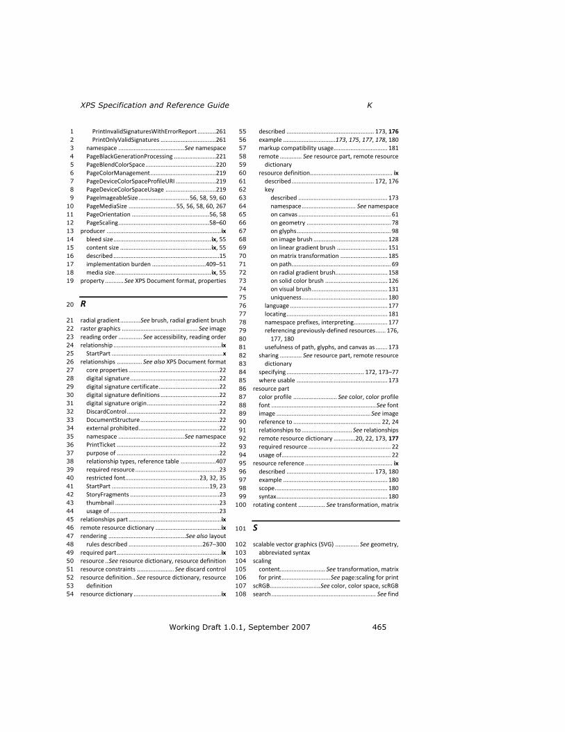
XPS Specification and Reference Guide K
Working Draft 1.0.1, September 2007 465
PrintInvalidSignaturesWithErrorReport ...........261 1
PrintOnlyValidSignatures .................................261 2
namespace ....................................... See namespace 3
PageBlackGenerationProcessing .........................221 4
PageBlendColorSpace ..........................................220 5
PageColorManagement .......................................219 6
PageDeviceColorSpaceProfileURI ........................219 7
PageDeviceColorSpaceUsage ..............................219 8
PageImageableSize .............................. 56, 58, 59, 60 9
PageMediaSize ............................ 55, 56, 58, 60, 267 10
PageOrientation .............................................. 56, 58 11
PageScaling ...................................................... 58–60 12
producer .................................................................... ix 13
bleed size .......................................................... ix, 55 14
content size ...................................................... ix, 55 15
described ...............................................................15 16
implementation burden ................................ 409–51 17
media size ......................................................... ix, 55 18
property ........... See XPS Document format, properties 19
R 20
radial gradient ............ See brush, radial gradient brush 21
raster graphics ............................................. See image 22
reading order .............. See accessibility, reading order 23
relationship ................................................................ ix 24
StartPart .................................................................. x 25
relationships ............... See also XPS Document format 26
core properties ......................................................22 27
digital signature .....................................................22 28
digital signature certificate ....................................22 29
digital signature definitions ...................................22 30
digital signature origin ...........................................22 31
DiscardControl .......................................................22 32
DocumentStructure ...............................................22 33
external prohibited ................................................22 34
namespace ....................................... See namespace 35
PrintTicket .............................................................22 36
purpose of .............................................................22 37
relationship types, reference table .....................407 38
required resource ..................................................23 39
restricted font ............................................ 23, 32, 35 40
StartPart .......................................................... 19, 23 41
StoryFragments .....................................................23 42
thumbnail ..............................................................23 43
usage of .................................................................23 44
relationships part ....................................................... ix 45
remote resource dictionary ....................................... ix 46
rendering .............................................. See also layout 47
rules described ............................................ 267–300 48
required part .............................................................. ix 49
resource .. See resource dictionary, resource definition 50
resource constraints ...................... See discard control 51
resource definition .. See resource dictionary, resource 52
definition 53
resource dictionary .................................................... ix 54
described .................................................... 173, 176 55
example ............................... 173, 175, 177, 178, 180 56
markup compatibility usage ................................ 181 57
remote ............. See resource part, remote resource 58
dictionary 59
resource definition ................................................. ix 60
described ................................................. 172, 176 61
key 62
described ..................................................... 173 63
namespace ................................ See namespace 64
on canvas ....................................................... 61 65
on geometry .................................................. 78 66
on glyphs ........................................................ 98 67
on image brush ............................................ 128 68
on linear gradient brush .............................. 151 69
on matrix transformation ............................ 185 70
on path ........................................................... 69 71
on radial gradient brush............................... 158 72
on solid color brush ..................................... 126 73
on visual brush ............................................. 131 74
uniqueness ................................................... 180 75
language .......................................................... 177 76
locating ............................................................ 181 77
namespace prefixes, interpreting .................... 177 78
referencing previously-defined resources ...... 176, 79
177, 180 80
usefulness of path, glyphs, and canvas as ....... 173 81
sharing ............. See resource part, remote resource 82
dictionary 83
specifying .............................................. 172, 173–77 84
where usable ...................................................... 173 85
resource part 86
color profile .......................... See color, color profile 87
font .............................................................. See font 88
image ........................................................ See image 89
reference to .................................................... 22, 24 90
relationships to .............................. See relationships 91
remote resource dictionary .............20, 22, 173, 177 92
required resource ................................................. 22 93
usage of................................................................. 22 94
resource reference .................................................... ix 95
described .................................................... 173, 180 96
example .............................................................. 180 97
scope ................................................................... 180 98
syntax .................................................................. 180 99
rotating content ................ See transformation, matrix 100
S 101
scalable vector graphics (SVG) .............. See geometry, 102
abbreviated syntax 103
scaling 104
content........................... See transformation, matrix 105
for print ............................. See page:scaling for print 106
scRGB.............................. See color, color space, scRGB 107
search .............................................................. See find 108

K Index
466 Working Draft 1.0.1, September 2007
section ...................... See document structure, section 1
segment .................................. See geometry, segment 2
selection 3
behavior .............................................................. 246 4
caret stop ...................................................... 98, 119 5
document structure, enabled by ................. 223, 246 6
fragment type, behavior depending on ............... 246 7
mentioned ........................................... 111, 119, 223 8
order .................................................................... 246 9
recommended ..................................................... 246 10
shear .................................. See transformation, matrix 11
signature definitions .................... See digital signature 12
signature spot .......... x, See digital signature, signature 13
definitions 14
simple ordering ........................................................... x 15
size terminology ................. See page, size terminology 16
skewing content ................. See transformation, matrix 17
sRGB ................................. See color, color space, sRGB 18
starting part ...................... See relationships, StartPart 19
story ............................. See document structure, story 20
story fragment ............. See document structure, story 21
fragment 22
stream ......................................................................... x 23
stretching content .............. See transformation, matrix 24
stroke 25
brush ..................................... See path, stroke brush 26
consistent nominal width ........... See stroke, hairline 27
contour rendering ............................................... 288 28
dash 29
cap ................................................................... 289 30
flat ................................................................ 289 31
round ............................................................ 290 32
square ........................................................... 289 33
style ................................................................ 69 34
triangle ......................................................... 290 35
offset .................................................................. 69 36
overlapping ...................................................... 291 37
style ................................................................... 69 38
drawing algorithm, symmetry of ......................... 288 39
edge parallelization ............................................. 288 40
fill rule, independence from ................................ 298 41
hairline ................................................................ 298 42
line 43
cap ................................................................... 291 44
end ................................................................. 69 45
flat ................................................................ 292 46
for dashed stroke ......................................... 292 47
round ............................................................ 292 48
square ........................................................... 292 49
start ................................................................ 69 50
triangle ......................................................... 292 51
join 52
bevel ............................................................. 294 53
miter ....................................................... 295–97 54
round ............................................................ 293 55
style ................................................................ 69 56
miter limit .......................................................... 69 57
pixel snapping ................................................... 69 58
thin stroke anti-aliasing behavior .................... 269 59
zero-length, avoided ......................................... 82 60
multi-figure path, behavior with ......................... 298 61
phase control ...................................................... 288 62
segments, mixed stroked and non-stroked ........ 298 63
thickness ............................................................... 69 64
T 65
table .... See document structure, table, See document 66
structure, table 67
table of contents ....... See document structure, outline 68
text 69
baseline ............................... See text, glyph, baseline 70
bidirectional .................................................. 98, 115 71
bold ................................... See text, style simulation 72
clipping .................................................. See clipping 73
fill brush ........................................................ 98, 124 74
font ....................................................... See also font 75
device font, reference to ........................... 98, 118 76
reference to ....................................................... 98 77
glyph 78
advance width .......................... 104, 105, 109, 110 79
baseline ........................................................... 104 80
black box ......................................................... 104 81
cluster map........................... 105–8, 109, 110, 111 82
indices 83
described ..................................................... 109 84
reference to non-existant glyph .................. 109 85
restriction of length ..................................... 109 86
specifying ....................................................... 98 87
syntax ........................................................... 109 88
metrics ............................................................ 104 89
offset ........................................ 105, 109, 110, 115 90
origin ....................................................... 104, 105 91
origin, sideways ............................................... 104 92
side-bearing, bottom ....................................... 105 93
side-bearing, left ............................................. 104 94
side-bearing, right ........................................... 104 95
side-bearing, top ............................................. 105 96
glyphs usage for .................................................... 97 97
italic .................................. See text, style simulation 98
markup .................................................................. 98 99
markup examples ............................................... 121 100
markup optimization .......................................... 120 101
opacity .................................................... See opacity 102
opacity mask .................................. See opacity mask 103
position ........................... See also text, glyph, offset 104
horizontal text ................................................... 98 105
vertical text ..................................................... 112 106
sideways (vertical) ................................................ 98 107
advance width ......................................... 109, 113 108
bidirectional text, intersection with ................ 114 109
described ......................................................... 112 110
example, sideways .......................................... 116 111

XPS Specification and Reference Guide K
Working Draft 1.0.1, September 2007 467
example, vertical ...................................... 116, 117 1
horizontal text, including .................................113 2
origin calculation ..............................................113 3
vertical glyphs, preference for .........................113 4
size .........................................................................98 5
style simulation ............................................. 98, 112 6
transformation ........................... See transformation 7
underline ..................................................... See path 8
Unicode string ............................ See also text, glyph 9
escaping open brace character ........................111 10
mapping code units to glyphs ..........................105 11
normalization prohibited .................................111 12
specifying ...........................................................98 13
Unicode control marks, inclusion of ................111 14
Unicode scalar value, split into code units .......105 15
unmappable code unit behavior ......................111 16
usage of ............................................................111 17
UTF-16 code units, consisting of ......................105 18
vertical .......................... See text, sideways (vertical) 19
thread .......................... See document structure, story 20
thumbnail .................................................................... x 21
described ......................................................... 20, 30 22
formats ..................................................... See image 23
parts ........................................................... See parts 24
relationship ............................................................23 25
usage .....................................................................30 26
TIFF ....................................................... See image, TIFF 27
transformation 28
composability ......................................................268 29
described ..................................................... 185, 268 30
effective transform .................... See transformation, 31
composability 32
elements applied to ..................................... 171, 172 33
matrix 34
abbreviated syntax ...........................................186 35
abbreviated syntax example ............................189 36
described .........................................................185 37
example ...........................................................187 38
inverting x-axis .................................................186 39
inverting y-axis .................................................186 40
multiplying .......................................................185 41
positioning .......................................................187 42
rotating ............................................................187 43
scaling ..............................................................186 44
skewing ............................................................186 45
specifying .........................................................185 46
mentioned ...........................................................267 47
non-invertible transform, rendering of elements 48
with ..................................................................268 49
of brush ...............................................................125 50
of canvas ........................................................ 61, 189 51
of geometry ................................................... 78, 192 52
of glyphs ........................................................ 98, 191 53
of image brush ............................................. 128, 193 54
of linear gradient brush ............................... 151, 197 55
of path ........................................................... 69, 190 56
of radial gradient brush ............................... 158, 198 57
of tiles ................................................................. 194 58
of tiles, example .................................................. 196 59
of visual brush ............................................. 131, 194 60
transparency .............................................. See opacity 61
TrueType collection (TTC) font ........ See font:TrueType 62
collection (TTC) 63
TrueType font .................................. See font:TrueType 64
V 65
vector graphics ............................................... See path 66
versioning ............................ See markup compatibility 67
W 68
whitespace ............... See XPS Document format, XML, 69
whitespace 70
Windows Color System (WCS) . See color, color profile, 71
Windows Color System (WCS) profile 72
Windows Media Photo ..... See image, Windows Media 73
Photo 74
X 75
XML ........................... See XPS Document format, XML 76
XML namespaces ........ See namespace; XPS Document 77
format, XML, namespaces 78
XML Paper Specification 79
document format ............ See XPS Document format 80
organization of ...................................................... 16 81
XPS Document format ..................................... x, 16, 19 82
content types ...................................................... 406 83
described .......................................................... 1, 49 84
example ................................................................ 21 85
extensibility ...................... See markup compatibility 86
fixed payload ................................................... vii, 19 87
fixed payload root ........................................... vii, 19 88
illustrated .............................................................. 18 89
language .............................................. See language 90
markup elements .......................... See XPS elements 91
parts ................................................................ 18, 19 92
payload ................................................................. 19 93
properties 94
attribute syntax ................................................. 45 95
composability ............................................ 45, 171 96
described ........................................................... 45 97
element syntax .................................................. 45 98
model ................................................................ 44 99
ordering ............................................................. 46 100
property attribute .............................................. ix 101
property element ............................................... ix 102
property value .............................................. ix, 45 103
property ................................................................. ix 104
relationship types ............................................... 407 105
relationships ................................................... 18, 22 106

K Index
468 Working Draft 1.0.1, September 2007
root ........................................................................ 49 1
versioning ......................... See markup compatibility 2
XML 3
DTDs prohibited ................................................. 44 4
markup design ................................................... 42 5
markup model .............................................. 44–47 6
namespaces ............................................... 44, 405 7
Unicode encodings permitted............................ 43 8
usage .................................................................. 43 9
whitespace ......................................................... 47 10
XML and XSI namespace usage .......................... 44 11
XML schema (XSD) 12
characteristics .................................................... 44 13
discard control schema .................................... 391 14
document structure schema ............................ 385 15
resource dictionary key schema ...................... 383 16
signature definitions schema ........................... 359 17
validity requirement .......................................... 44 18
XPS Document schema .................................... 361 19
XPS elements 20
digital signature 21
<Intent> ................................................... 264, 322 22
<SignatureDefinition> .............................. 262, 348 23
<SignatureDefinitions> ............................ 262, 349 24
<SignBy> .................................................. 265, 348 25
<SigningLocation> .................................... 265, 349 26
<SpotLocation> ........................................ 263, 350 27
discard control 28
<Discard> ................................................. 256, 306 29
<DiscardControl> ..................................... 256, 307 30
document structure 31
<DocumentOutline> ................................ 226, 307 32
<DocumentStructure.Outline> ................ 226, 309 33
<DocumentStructure> ............................. 224, 308 34
<FigureStructure> .................................... 242, 309 35
<ListItemStructure> ................................. 242, 326 36
<ListStructure> ......................................... 241, 327 37
<NamedElement> .................................... 243, 328 38
<OutlineEntry> ......................................... 227, 328 39
<ParagraphStructure> .............................. 239, 330 40
<SectionStructure> .................................. 239, 348 41
<Story> ..................................................... 228, 351 42
<StoryBreak> ............................................ 239, 352 43
<StoryFragment> ..................................... 235, 352 44
<StoryFragmentReference> ..................... 229, 353 45
<StoryFragments> .................................... 234, 353 46
<TableCellStructure> ............................... 241, 354 47
<TableRowGroupStructure> .................... 240, 355 48
<TableRowStructure> .............................. 240, 355 49
<TableStructure> ..................................... 240, 355 50
document-level 51
<DocumentReference> .............................. 49, 308 52
<FixedDocument> ...................................... 50, 309 53
<FixedDocumentSequence> ...................... 49, 310 54
<LinkTarget> .............................................. 52, 326 55
<PageContent.LinkTargets> ...................... 51, 330 56
<PageContent> .......................................... 50, 329 57
page-level 58
<ArcSegment> ........................................... 82, 301 59
<Canvas.Clip> .......................................... 182, 305 60
<Canvas.OpacityMask> ........................... 200, 305 61
<Canvas.RenderTransform> .................... 189, 306 62
<Canvas.Resources> ................................ 175, 306 63
<Canvas> ................................................... 61, 302 64
<FixedPage.Resources> ........................... 173, 311 65
<FixedPage> .............................................. 53, 310 66
<Glyphs.Clip> ........................................... 184, 317 67
<Glyphs.Fill> ............................................ 124, 317 68
<Glyphs.OpacityMask> ............................ 202, 318 69
<Glyphs.RenderTransform> .................... 191, 319 70
<Glyphs> .................................................... 98, 312 71
<GradientStop> ....................................... 166, 319 72
<ImageBrush.Transform> ........................ 193, 322 73
<ImageBrush> ......................................... 127, 320 74
<LinearGradientBrush.GradientStops> ... 157, 325 75
<LinearGradientBrush.Transform> .......... 197, 325 76
<LinearGradientBrush> ........................... 151, 323 77
<MatrixTransform> ................................. 185, 327 78
<Path.Clip> .............................................. 183, 337 79
<Path.Data> ............................................... 74, 337 80
<Path.Fill> .................................................. 75, 337 81
<Path.OpacityMask> ............................... 201, 338 82
<Path.RenderTransform> ........................ 190, 338 83
<Path.Stroke> ............................................ 76, 338 84
<Path> ....................................................... 68, 331 85
<PathFigure> ............................................. 81, 339 86
<PathGeometry.Transform> ................... 192, 341 87
<PathGeometry> ....................................... 78, 339 88
<PolyBezierSegment> ................................ 86, 341 89
<PolyLineSegment> ................................... 87, 342 90
<PolyQuadraticBezierSegment> ................ 88, 342 91
<RadialGradientBrush.GradientStops> ... 165, 345 92
<RadialGradientBrush.Transform> .......... 198, 346 93
<RadialGradientBrush> ........................... 158, 343 94
<ResourceDictionary> ............................. 176, 346 95
<SolidColorBrush> ................................... 126, 350 96
<VisualBrush.Transform> ........................ 194, 358 97
<VisualBrush.Visual> ............................... 133, 358 98
<VisualBrush> .......................................... 131, 356 99
Z 100
ZIP 101
archive ............................................................... x, 18 102
item .......................................................................... x 103
utilities .................................................................. 33 104
105


![[MS-ES6]: Microsoft Edge / Internet Explorer ECMA-262 ... · 3 / 96 [MS-ES6] - v20161102 Microsoft Edge / Internet Explorer ECMA-262 ECMAScript Language Specification (Sixth Edition)](https://img.pdfslide.us/doc/110x75/600da0da344a493cab07efa7/ms-es6-microsoft-edge-internet-explorer-ecma-262-3-96-ms-es6-v20161102.jpg)


![[MS-ES6]: Microsoft Edge / Internet Explorer ECMA-262 ... · 3 / 92 [MS-ES6] - v20160719 Microsoft Edge / Internet Explorer ECMA-262 ECMAScript Language Specification (Sixth Edition)](https://img.pdfslide.us/doc/110x75/5f62d67d3a9e63592a3f7225/ms-es6-microsoft-edge-internet-explorer-ecma-262-3-92-ms-es6-v20160719.jpg)
![[MS-ES5]: Internet Explorer ECMA-262 ECMAScript Language ... · 3 / 37 [MS-ES5] - v20161102 Internet Explorer ECMA-262 ECMAScript Language Specification (Fifth Edition) Standards](https://img.pdfslide.us/doc/110x75/5ed792d867b53e06555d28d7/ms-es5-internet-explorer-ecma-262-ecmascript-language-3-37-ms-es5-v20161102.jpg)
![Unifier Licensing Information User Manual - Oracle · 2021. 4. 9. · a part of the Office Open XML ECMA Specification (ECMA-376, [1]). As defined in section 9.4 of the ECMA bylaws](https://img.pdfslide.us/doc/110x75/614296a0d9e4dc11f47f251e/unifier-licensing-information-user-manual-oracle-2021-4-9-a-part-of-the-office.jpg)