Embed Size (px)
Citation preview

00-02-0789 2012-04-26 Section 78
XM500
Configuration Tool Version 2.0
Installation and Operations Manual

In order to consistently bring you the highest quality, full featured products, we reserve the right to change our specifications and designs at any time. The latest version of this manual can be found at www.fwmurphy.com.
Please read the following information before installing.
BEFORE BEGINNING INSTALLATION OF THIS MURPHY PRODUCT:
Read and follow all installation instructions.
Please contact FW MURPHY if you have any questions.
Contents
Introduction .........................................................................................................1
XM500 Specifications ........................................................................................................... 1
Getting Started ...................................................................................................2
Installing the USB Driver ...................................................................................................... 2
Connecting the XM500 to Your Computer............................................................................ 4
Installing XM500 Software.................................................................................................... 6
System Requirements ...................................................................................................... 6
Processor ......................................................................................................................... 6
Monitor Requirement ....................................................................................................... 6
Recommended Operating Systems ................................................................................. 6
Software Installation Instructions ..................................................................................... 7
Launching the Application ................................................................................................ 9
Using the XM500 Application ........................................................................ 10
Switchable Bootloader and Power Modes .......................................................................... 10
Normal Operation Mode ................................................................................................. 10
Application Download Mode .......................................................................................... 10
Configuration Load Mode ............................................................................................... 10
XM500 Tabs, Screens, and Text Box Explanations.................................... 11
Settings Tab ....................................................................................................................... 11
Verifying Jumper Positions on the XM500 ..................................................................... 14
Opening XM500 Enclosure ............................................................................................ 14
Verifying Jumper Positions on the RS485 Converter ..................................................... 17
Mag Pickup Tab ................................................................................................................. 18
Digital Inputs Tab ............................................................................................................... 22
Analog Inputs Tab .............................................................................................................. 24
Analog Thermocouple .................................................................................................... 25
Proprietary Analog SPN Options.................................................................................... 26
Sender Raw A/D Counts ................................................................................................ 27
Fields and Descriptions Table ........................................................................................ 28
Digital Outputs Tab ............................................................................................................ 31
Shutdown Output ........................................................................................................... 31
Warning Output .............................................................................................................. 32
Eng Running Output ...................................................................................................... 33
Hour Meter Tab .................................................................................................................. 34
Custom Sender Tab ........................................................................................................... 35
Eng Run State Tab ............................................................................................................. 36
Pre-Programmed Resistive Senders ............................................................ 37
VDO 250 Temperature ................................................................................................... 37
VDO 300 Temperature ................................................................................................... 37
VDO 320 Temperature ................................................................................................... 37
VDO 400 Temperature ................................................................................................... 37
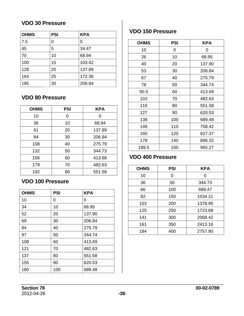
VDO 30 Pressure ........................................................................................................... 38
VDO 80 Pressure ........................................................................................................... 38
VDO 100 Pressure ......................................................................................................... 38
VDO 150 Pressure ......................................................................................................... 38
VDO 400 Pressure ......................................................................................................... 38
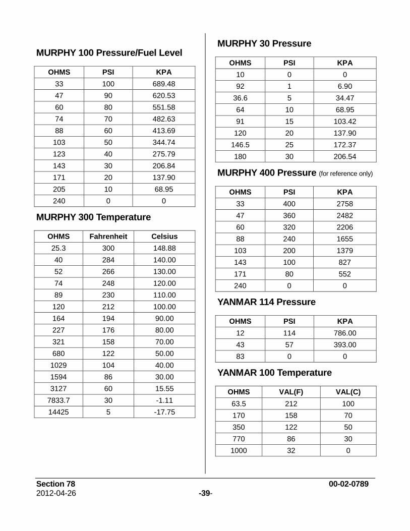
MURPHY 100 Pressure/Fuel Level ................................................................................ 39
MURPHY 300 Temperature ........................................................................................... 39
MURPHY 30 Pressure ................................................................................................... 39
MURPHY 400 Pressure ................................................................................................. 39
YANMAR 114 Pressure ................................................................................................. 39
YANMAR 100 Temperature ........................................................................................... 39
Menu Bar .......................................................................................................... 40
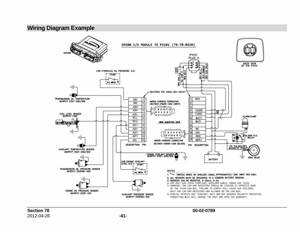
Wiring Diagram Example ............................................................................... 41
Section 78 00-02-0789 2012-04-26 -1-
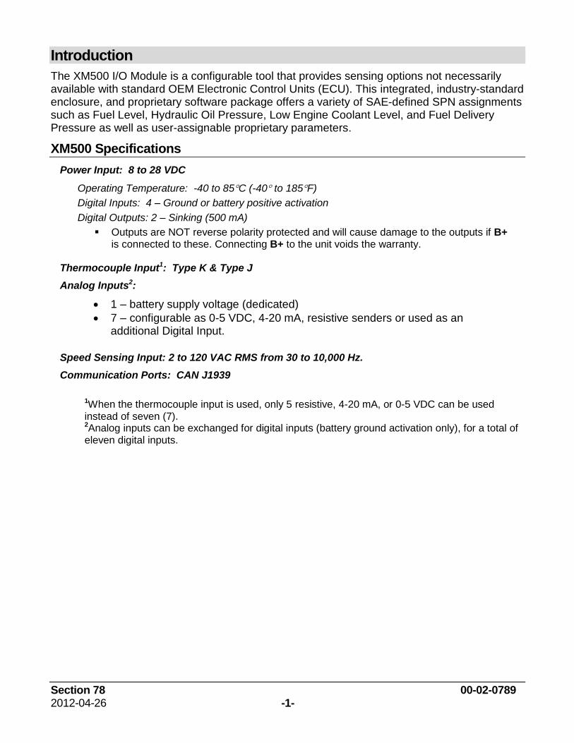
Introduction
The XM500 I/O Module is a configurable tool that provides sensing options not necessarily available with standard OEM Electronic Control Units (ECU). This integrated, industry-standard enclosure, and proprietary software package offers a variety of SAE-defined SPN assignments such as Fuel Level, Hydraulic Oil Pressure, Low Engine Coolant Level, and Fuel Delivery Pressure as well as user-assignable proprietary parameters.
XM500 Specifications
Power Input: 8 to 28 VDC
Operating Temperature: -40 to 85C (-40 to 185F)
Digital Inputs: 4 – Ground or battery positive activation
Digital Outputs: 2 – Sinking (500 mA)
Outputs are NOT reverse polarity protected and will cause damage to the outputs if B+ is connected to these. Connecting B+ to the unit voids the warranty.
Thermocouple Input1: Type K & Type J
Analog Inputs2:
1 – battery supply voltage (dedicated)
7 – configurable as 0-5 VDC, 4-20 mA, resistive senders or used as an additional Digital Input.
Speed Sensing Input: 2 to 120 VAC RMS from 30 to 10,000 Hz.
Communication Ports: CAN J1939
1When the thermocouple input is used, only 5 resistive, 4-20 mA, or 0-5 VDC can be used instead of seven (7). 2Analog inputs can be exchanged for digital inputs (battery ground activation only), for a total of eleven digital inputs.
Section 78 00-02-0789 2012-04-26 -2-
Getting Started
NOTE: Do not connect the USB Serial Adapter to the USB port of your computer before you finish installing the UBS COM driver.
A USB connection is required for transferring the configuration from the PC to the XM500.
While the configuration software will function on any PC or laptop running Windows, it will not perform transfers using the USB driver unless the operating system supports USB function. Operating systems supporting USB function include 2000, XP, 2003, Vista, and Windows7. Any or all of the screens in the following steps, or other screens not shown, may give you information about installing the USB COM driver or ask you to take an action. You may need Administrator Privileges to install software on the computer.
Installing the USB Driver
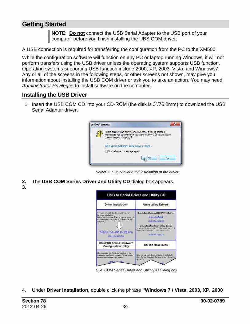
1. Insert the USB COM CD into your CD-ROM (the disk is 3”/76.2mm) to download the USB Serial Adapter driver.
Select YES to continue the installation of the driver.
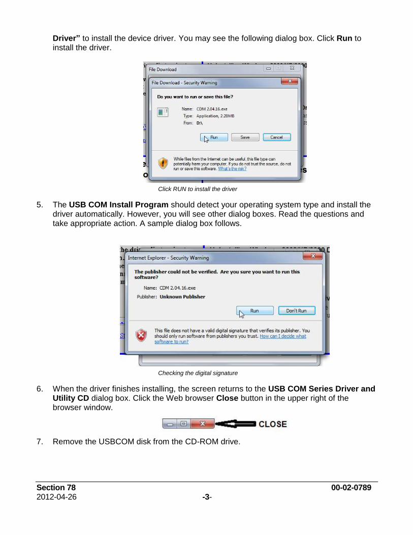
2. The USB COM Series Driver and Utility CD dialog box appears. 3.
USB COM Series Driver and Utility CD Dialog box
4. Under Driver Installation, double click the phrase “Windows 7 / Vista, 2003, XP, 2000
Section 78 00-02-0789 2012-04-26 -3-
Driver” to install the device driver. You may see the following dialog box. Click Run to install the driver.
Click RUN to install the driver
5. The USB COM Install Program should detect your operating system type and install the driver automatically. However, you will see other dialog boxes. Read the questions and take appropriate action. A sample dialog box follows.
Checking the digital signature
6. When the driver finishes installing, the screen returns to the USB COM Series Driver and Utility CD dialog box. Click the Web browser Close button in the upper right of the browser window.
7. Remove the USBCOM disk from the CD-ROM drive.

Section 78 00-02-0789 2012-04-26 -4-
Connecting the XM500 to Your Computer
The following table shows what you will need to connect the XM500 to a computer: It also walks you through connecting the cables and devices.
USB to RS485 Converter
Note: Make sure the USB Driver has been installed before connecting the hardware to the computer.
USB Cable
1. Connect the USB cable square connector end to the RS485 converter.
Programming Cable
2. Connect the 9-pin connector to the RS485 converter.
AC Adapter Cable
3. Connect the AC Adapter Cable to the Programming Cable.
Cables to XM500
4. Connect the Power Supply/Programming cable to the XM500.
Section 78 00-02-0789 2012-04-26 -5-
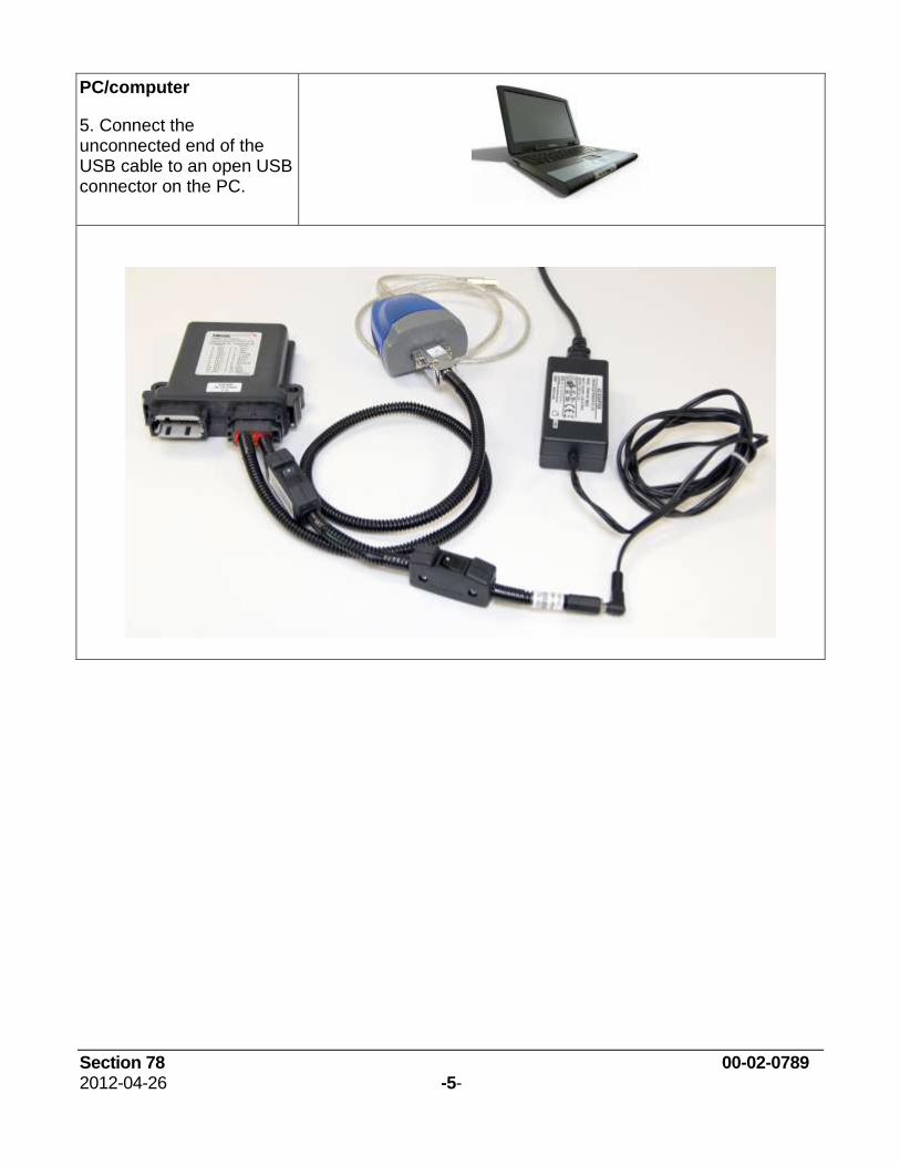
PC/computer
5. Connect the unconnected end of the USB cable to an open USB connector on the PC.
Section 78 00-02-0789 2012-04-26 -6-
Installing XM500 Software
System Requirements
A USB 1.1 connection is required for transferring the configuration from PC to the XM500.
While the configuration software will function on any PC or laptop running Windows, it will not perform transfers using the USB driver unless the operating system supports USB function. USB supported operating systems include Win98SE, NT, XP, and Windows 7.
Serial transfers using standard communication ports (COM1, COM2) should be possible on all Windows platforms.
The following details the recommended system requirements for the XM500 Configuration software,
Processor
Dual Core
Intel Pentium D, 3 GHz & above
Intel Core Duo, 2 GHz & above
Intel Core 2 Duo, 2 GHz & above
Single Core
Intel Pentium 4, 3 GHZ & above
Intel Core Solo, 1.8 GHz and above
2 GB System RAM and above
USB connection on the PC
Monitor Requirement
Color monitor with resolution of 1024 x 768 pixels or higher
Recommended Operating Systems
Windows XP Professional with Service Pack installed and Microsoft.Net Framework 4.0
Section 78 00-02-0789 2012-04-26 -7-
Software Installation Instructions
Use the following steps to install the configuration software on a PC or laptop. Make sure you have installed the USB Driver before installing the XM500 software.
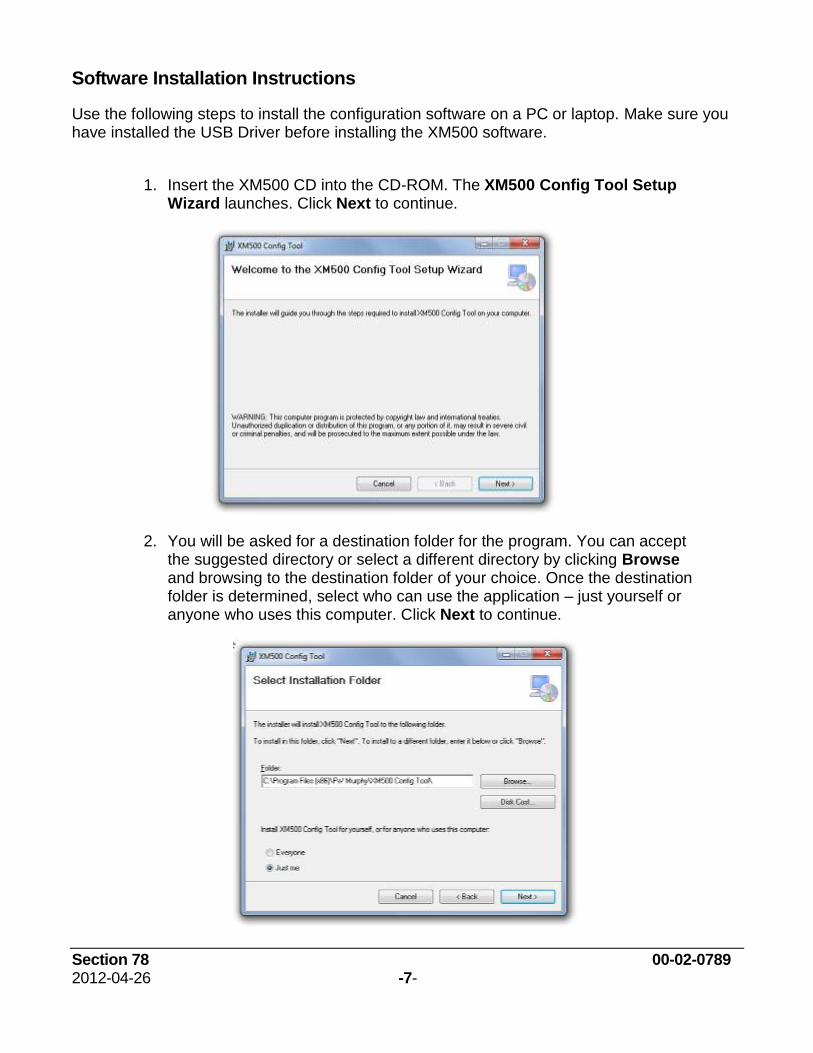
1. Insert the XM500 CD into the CD-ROM. The XM500 Config Tool Setup Wizard launches. Click Next to continue.
2. You will be asked for a destination folder for the program. You can accept the suggested directory or select a different directory by clicking Browse and browsing to the destination folder of your choice. Once the destination folder is determined, select who can use the application ‒ just yourself or anyone who uses this computer. Click Next to continue.
Section 78 00-02-0789 2012-04-26 -8-
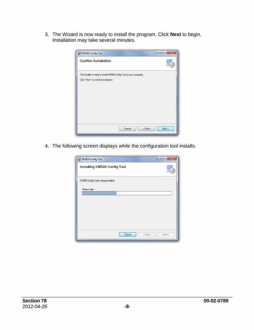
3. The Wizard is now ready to install the program. Click Next to begin. Installation may take several minutes.
4. The following screen displays while the configuration tool installs.
Section 78 00-02-0789 2012-04-26 -9-
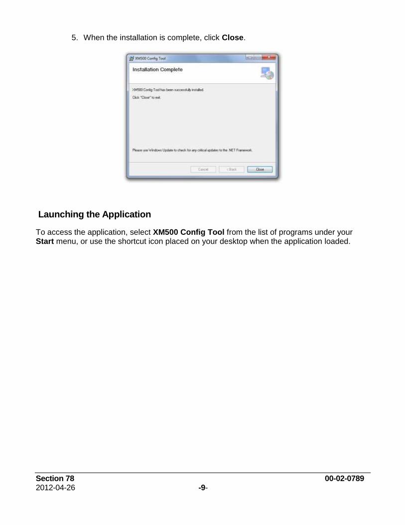
5. When the installation is complete, click Close.
Launching the Application
To access the application, select XM500 Config Tool from the list of programs under your Start menu, or use the shortcut icon placed on your desktop when the application loaded.

Section 78 00-02-0789 2012-04-26 -10-
Using the XM500 Application
The XM500 is a configurable Input/Output (I/O) module designed to bring analog input, and digital input and output information onto the SAE J1939 Controller Area Network (CAN). The XM500 Config Tool provides a user-friendly interface allowing the user to create or change the configuration used on the XM500 unit.
Switchable Bootloader and Power Modes
The XM500 uses a switchable-bootloader pin to toggle between the three modes of operation:
Normal Operation Mode
For normal operating mode, the Bootloader switch is in the OFF position and remains OFF when main power is applied (click the power switch to the ON position).
Application Download Mode
When preparing to load the application, have the Bootloader switch in the ON position when main power is applied (click the power switch to the ON position).
Configuration Load Mode
For the Configuration Load Mode, have the Bootloader switch in the OFF position.
Verify Bootloader switch is OFF, and then turn the main power ON (click the power switch to the ON position). Once the main power is ON, click the Bootloader switch ON.
If the Bootloader switch is in the wrong position for the action you are trying to perform, a warning message displays.
Section 78 00-02-0789 2012-04-26 -11-
XM500 Tabs, Screens, and Text Box Explanations
Start the configuration on the Setting Tab where you select basic display and feature options. Then configure your Digital Inputs, Analog Inputs, and Digital Outputs. Depending on your configuration, you may also set parameters, triggers, sources, or values on the Hour Meter, Custom Sender, and Eng Run State Tabs. Starting with the Settings Tab below, this document explains the selections available on each Tab screen. This application contains Help at the documentation level from the Menu Bar Help button or explanations and information for specific items at the F1 Help level.
Settings Tab
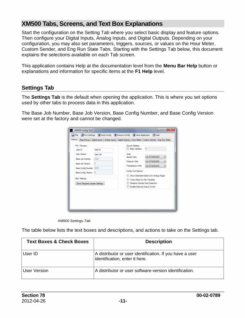
The Settings Tab is the default when opening the application. This is where you set options used by other tabs to process data in this application.
The Base Job Number, Base Job Version, Base Config Number, and Base Config Version were set at the factory and cannot be changed.
XM500 Settings Tab
The table below lists the text boxes and descriptions, and actions to take on the Settings tab.
Text Boxes & Check Boxes Description
User ID A distributor or user identification. If you have a user identification, enter it here.
User Version A distributor or user software-version identification.
Section 78 00-02-0789 2012-04-26 -12-
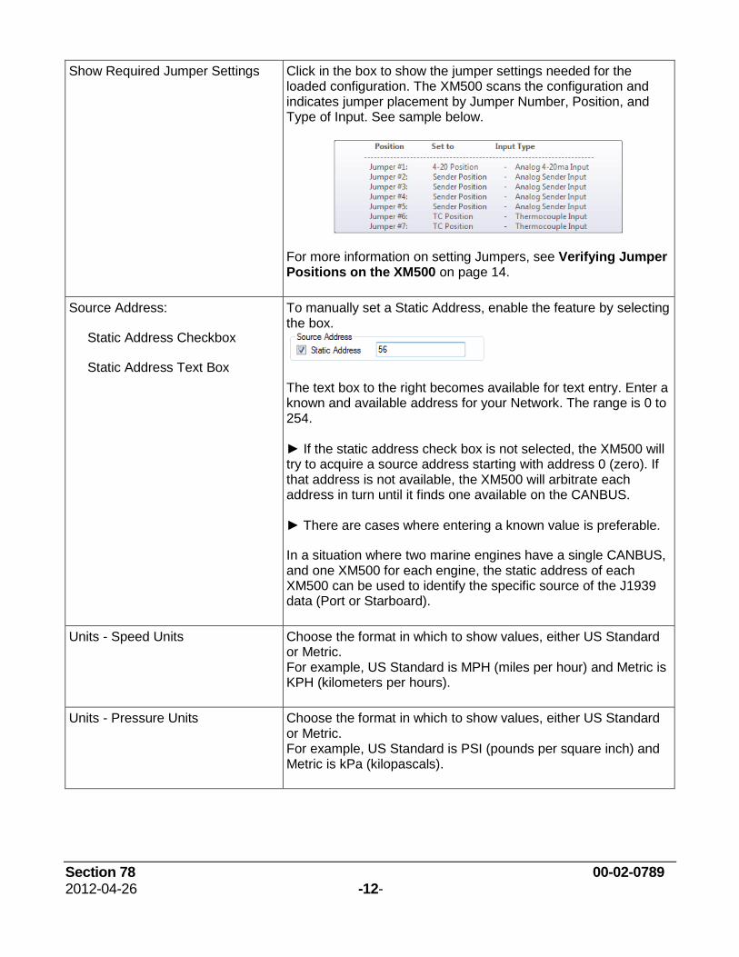
Show Required Jumper Settings Click in the box to show the jumper settings needed for the loaded configuration. The XM500 scans the configuration and indicates jumper placement by Jumper Number, Position, and Type of Input. See sample below.
For more information on setting Jumpers, see Verifying Jumper Positions on the XM500 on page 14.
Source Address:
Static Address Checkbox
Static Address Text Box
To manually set a Static Address, enable the feature by selecting the box.
The text box to the right becomes available for text entry. Enter a known and available address for your Network. The range is 0 to 254. ► If the static address check box is not selected, the XM500 will try to acquire a source address starting with address 0 (zero). If that address is not available, the XM500 will arbitrate each address in turn until it finds one available on the CANBUS. ► There are cases where entering a known value is preferable.
In a situation where two marine engines have a single CANBUS, and one XM500 for each engine, the static address of each XM500 can be used to identify the specific source of the J1939 data (Port or Starboard).
Units - Speed Units Choose the format in which to show values, either US Standard or Metric. For example, US Standard is MPH (miles per hour) and Metric is KPH (kilometers per hours).
Units - Pressure Units Choose the format in which to show values, either US Standard or Metric. For example, US Standard is PSI (pounds per square inch) and Metric is kPa (kilopascals).
Section 78 00-02-0789 2012-04-26 -13-
Units - Temperature Units Choose the format in which to show values, either US Standard or Metric. For example, US Standard shows degrees Fahrenheit (°F) and Metric shows degrees Celsius (°C).
Config Tool Options – Show Extended Options on Analog Pages
Select this option to show the true counts for the analog to digital converter associated with each channel. The Min A/D and Max A/D text boxes show on each Analog Input screen if the option is enabled. ► On the Analog Input screen, if you change the Hardware drop-down list from Sender to 4-20ma or 0-5V, the digital counts automatically fill. The 0-5V is the full range and shows the actual A-to-D counts. 4-20ma is scaled, but contains the necessary counts between 4 milliamps and 20 milliamps. Both are 10-bit analog to digital.
Each of the Config Tool Options has more information available. Press F1 while pausing on the phrase or check box.
Config Tool Options – Turbo Mode for File Transfers
Select this option to automatically increase the baud rate (transfer speed) at which the application and configurations are sent to the XM500. ► When configurations are uploaded from the XM500 the transfer is slower as Turbo cannot be applied to that end.
Config Tool Options – Resistive Sender Fault Detection
If this option is selected, a resistive sender with an open or shorted condition broadcasts a DM1 warning message with FMI 7.
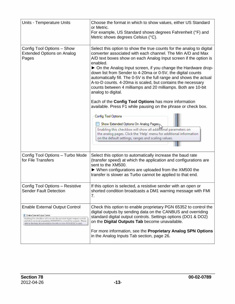
Enable External Output Control
Check this option to enable proprietary PGN 65352 to control the digital outputs by sending data on the CANBUS and overriding standard digital output controls. Settings options (DO1 & DO2) on the Digital Outputs Tab become unavailable.
For more information, see the Proprietary Analog SPN Options in the Analog Inputs Tab section, page 26.

Section 78 00-02-0789 2012-04-26 -14-
Verifying Jumper Positions on the XM500
The selections made on the Analog Input screen in Parameter 2-Hardware (Sender, 4-20ma, or 0-5V) affect jumper placement of the headers on the XM500 printed circuit board. Review the following graphics for opening the enclosure and proper jumper placement. Also, become familiar with the Settings Tab, Show Required Jumper Settings box on page 12.
Opening XM500 Enclosure
The XM500 enclosure has a snap-in header. Carefully slide a flathead screwdriver between the enclosure body and connector header. On both the left and right of the header, push the flat of the screwdriver sideways toward the enclosure body to pop the tab loose, and then slide connector header away from the enclosure body.
Section 78 00-02-0789 2012-04-26 -15-
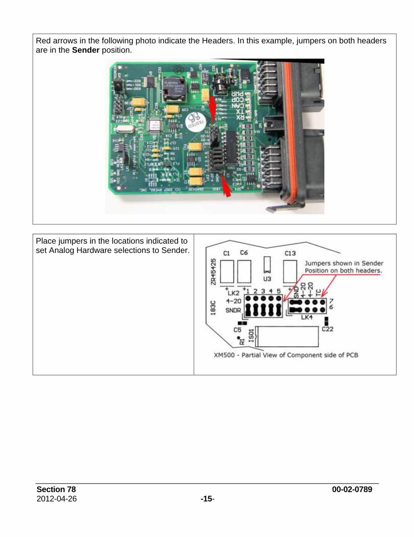
Red arrows in the following photo indicate the Headers. In this example, jumpers on both headers are in the Sender position.
Place jumpers in the locations indicated to set Analog Hardware selections to Sender.
Section 78 00-02-0789 2012-04-26 -16-
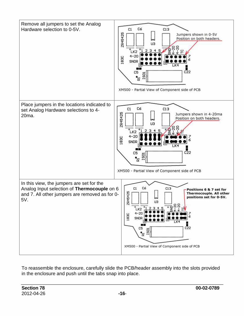
Remove all jumpers to set the Analog Hardware selection to 0-5V.
Place jumpers in the locations indicated to set Analog Hardware selections to 4-20ma.
In this view, the jumpers are set for the Analog Input selection of Thermocouple on 6 and 7. All other jumpers are removed as for 0-5V.
To reassemble the enclosure, carefully slide the PCB/header assembly into the slots provided in the enclosure and push until the tabs snap into place.

Section 78 00-02-0789 2012-04-26 -17-
Verifying Jumper Positions on the RS485 Converter
Jumper positions on the RS485 Converter printed circuit boards are set at the factory and should never need adjustment. However, if you are troubleshooting a problem, checking the jumper and switch settings may be necessary.
The RS485 can be equipped with one of two circuit boards. The following photos show both options and the arrows indicate the jumper positions and/or switch settings to check. These photos show the correct positions for jumpers and switches.
This RS485 Converter printed circuit board contains only jumpers.
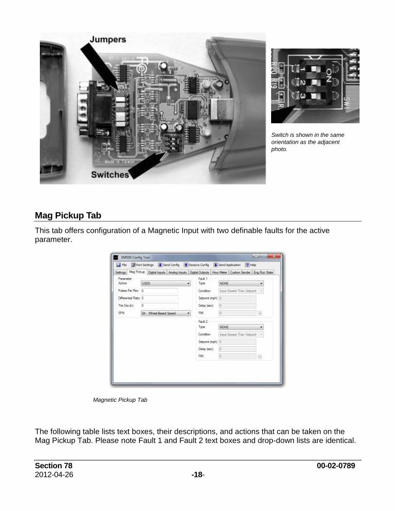
Section 78 00-02-0789 2012-04-26 -18-
Switch is shown in the same
orientation as the adjacent
photo.
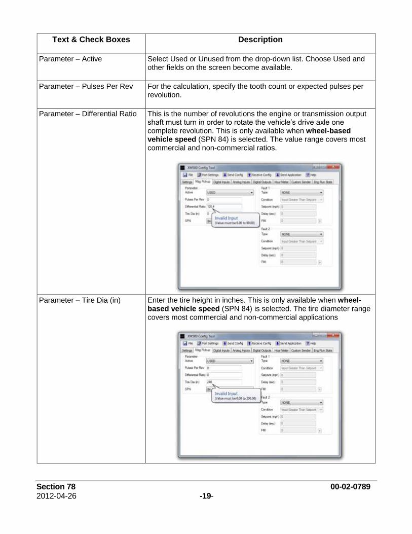
Mag Pickup Tab
This tab offers configuration of a Magnetic Input with two definable faults for the active parameter.
Magnetic Pickup Tab
The following table lists text boxes, their descriptions, and actions that can be taken on the Mag Pickup Tab. Please note Fault 1 and Fault 2 text boxes and drop-down lists are identical.
Section 78 00-02-0789 2012-04-26 -19-
Text & Check Boxes Description
Parameter – Active Select Used or Unused from the drop-down list. Choose Used and other fields on the screen become available.
Parameter – Pulses Per Rev For the calculation, specify the tooth count or expected pulses per revolution.
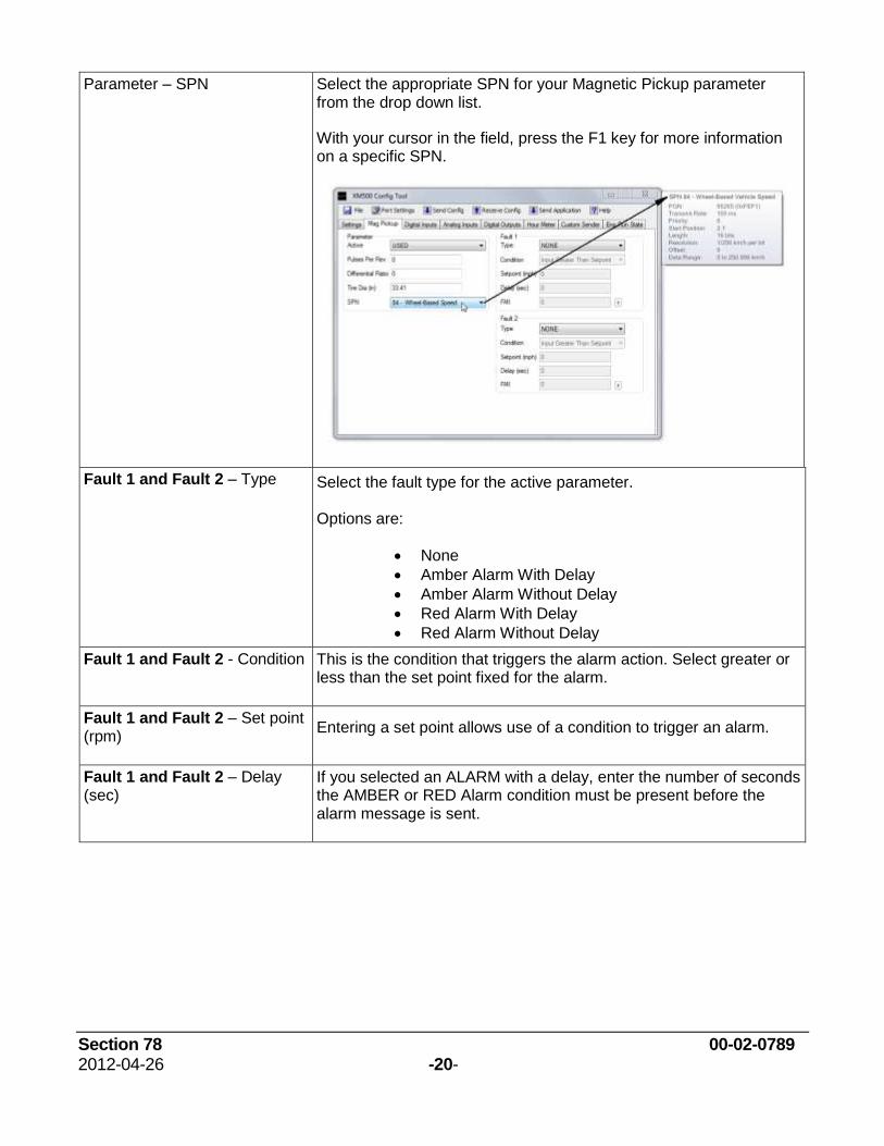
Parameter – Differential Ratio This is the number of revolutions the engine or transmission output shaft must turn in order to rotate the vehicle’s drive axle one complete revolution. This is only available when wheel-based vehicle speed (SPN 84) is selected. The value range covers most commercial and non-commercial ratios.
Parameter – Tire Dia (in) Enter the tire height in inches. This is only available when wheel-based vehicle speed (SPN 84) is selected. The tire diameter range covers most commercial and non-commercial applications
Section 78 00-02-0789 2012-04-26 -20-
Parameter – SPN Select the appropriate SPN for your Magnetic Pickup parameter from the drop down list.
With your cursor in the field, press the F1 key for more information on a specific SPN.
Fault 1 and Fault 2 – Type Select the fault type for the active parameter. Options are:
None
Amber Alarm With Delay
Amber Alarm Without Delay
Red Alarm With Delay
Red Alarm Without Delay
Fault 1 and Fault 2 - Condition This is the condition that triggers the alarm action. Select greater or less than the set point fixed for the alarm.
Fault 1 and Fault 2 – Set point (rpm)
Entering a set point allows use of a condition to trigger an alarm.
Fault 1 and Fault 2 – Delay (sec)
If you selected an ALARM with a delay, enter the number of seconds the AMBER or RED Alarm condition must be present before the alarm message is sent.
Section 78 00-02-0789 2012-04-26 -21-
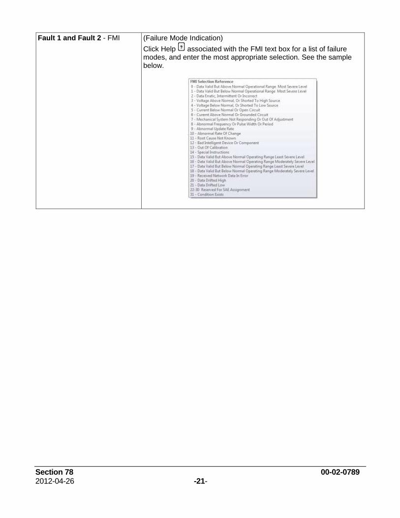
Fault 1 and Fault 2 - FMI (Failure Mode Indication)
Click Help associated with the FMI text box for a list of failure modes, and enter the most appropriate selection. See the sample below.
Section 78 00-02-0789 2012-04-26 -22-
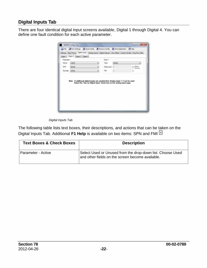
Digital Inputs Tab
There are four identical digital input screens available, Digital 1 through Digital 4. You can define one fault condition for each active parameter.
Digital Inputs Tab
The following table lists text boxes, their descriptions, and actions that can be taken on the
Digital Inputs Tab. Additional F1 Help is available on two items: SPN and FMI
Text Boxes & Check Boxes Description
Parameter - Active Select Used or Unused from the drop-down list. Choose Used and other fields on the screen become available.
Section 78 00-02-0789 2012-04-26 -23-
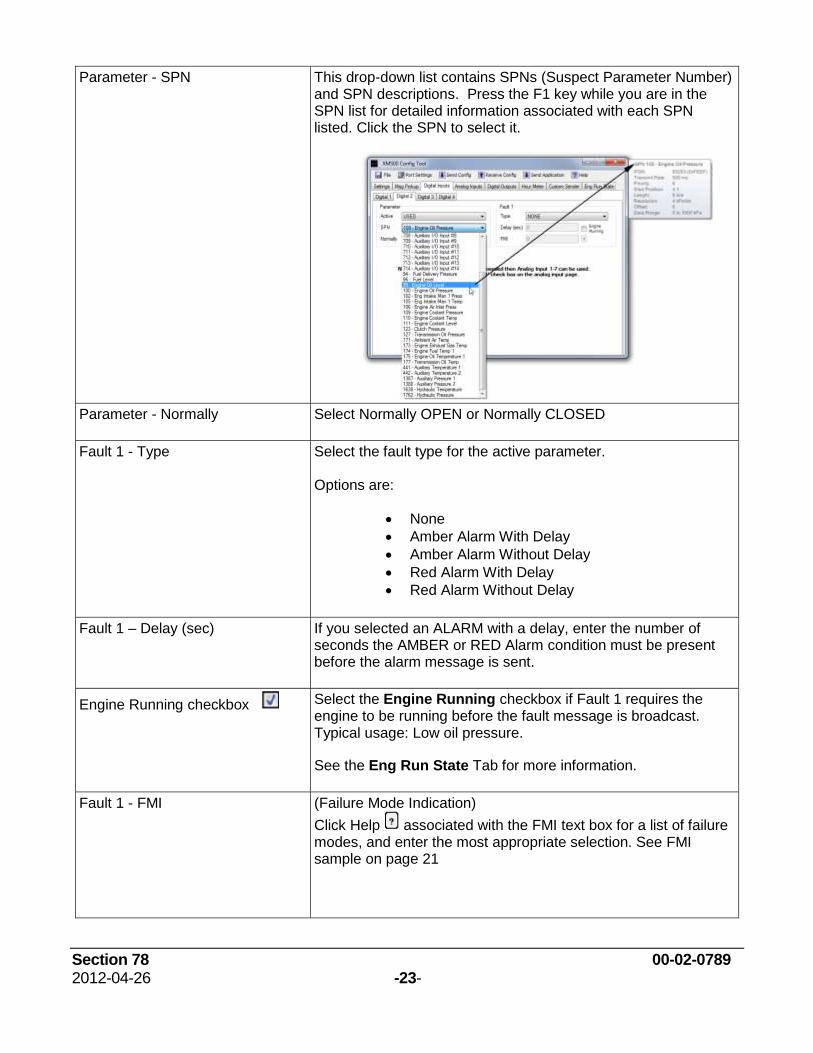
Parameter - SPN This drop-down list contains SPNs (Suspect Parameter Number) and SPN descriptions. Press the F1 key while you are in the SPN list for detailed information associated with each SPN listed. Click the SPN to select it.
Parameter - Normally Select Normally OPEN or Normally CLOSED
Fault 1 - Type Select the fault type for the active parameter. Options are:
None
Amber Alarm With Delay
Amber Alarm Without Delay
Red Alarm With Delay
Red Alarm Without Delay
Fault 1 – Delay (sec) If you selected an ALARM with a delay, enter the number of seconds the AMBER or RED Alarm condition must be present before the alarm message is sent.
Engine Running checkbox Select the Engine Running checkbox if Fault 1 requires the engine to be running before the fault message is broadcast. Typical usage: Low oil pressure.
See the Eng Run State Tab for more information.
Fault 1 - FMI (Failure Mode Indication)
Click Help associated with the FMI text box for a list of failure modes, and enter the most appropriate selection. See FMI sample on page 21
Section 78 00-02-0789 2012-04-26 -24-
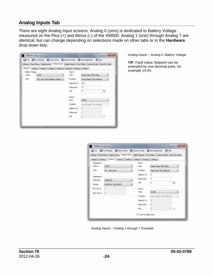
Analog Inputs Tab
There are eight Analog Input screens. Analog 0 (zero) is dedicated to Battery Voltage measured on the Plus (+) and Minus (–) of the XM500. Analog 1 (one) through Analog 7 are identical, but can change depending on selections made on other tabs or in the Hardware drop-down lists.
Analog Inputs – Analog 0, Battery Voltage
TIP: Fault Value Setpoint can be extended by one decimal point, for example 14.4V.
Analog Inputs – Analog 1 through 7 Example
Section 78 00-02-0789 2012-04-26 -25-
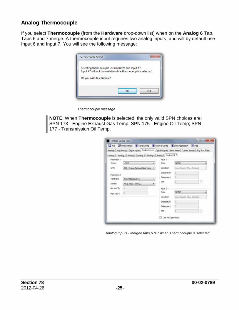
Analog Thermocouple
If you select Thermocouple (from the Hardware drop-down list) when on the Analog 6 Tab, Tabs 6 and 7 merge. A thermocouple input requires two analog inputs, and will by default use Input 6 and Input 7. You will see the following message:
Thermocouple message
NOTE: When Thermocouple is selected, the only valid SPN choices are: SPN 173 - Engine Exhaust Gas Temp; SPN 175 - Engine Oil Temp; SPN 177 - Transmission Oil Temp.
Analog Inputs - Merged tabs 6 & 7 when Thermocouple is selected
Section 78 00-02-0789 2012-04-26 -26-
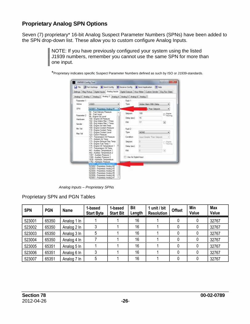
Proprietary Analog SPN Options
Seven (7) proprietary* 16-bit Analog Suspect Parameter Numbers (SPNs) have been added to the SPN drop-down list. These allow you to custom configure Analog Inputs.
NOTE: If you have previously configured your system using the listed J1939 numbers, remember you cannot use the same SPN for more than one input.
*Proprietary indicates specific Suspect Parameter Numbers defined as such by ISO or J1939-standards.
Analog Inputs – Proprietary SPNs
Proprietary SPN and PGN Tables
SPN PGN Name 1-based Start Byte
1-based Start Bit
Bit Length
1 unit / bit Resolution
Offset Min Value
Max Value
523001 65350 Analog 1 In 1 1 16 1 0 0 32767
523002 65350 Analog 2 In 3 1 16 1 0 0 32767
523003 65350 Analog 3 In 5 1 16 1 0 0 32767
523004 65350 Analog 4 In 7 1 16 1 0 0 32767
523005 65351 Analog 5 In 1 1 16 1 0 0 32767
523006 65351 Analog 6 In 3 1 16 1 0 0 32767
523007 65351 Analog 7 In 5 1 16 1 0 0 32767
Section 78 00-02-0789 2012-04-26 -27-
SPN PGN Name 1-based Start Byte
1-based Start Bit
Bit Length
1 unit / bit Resolution
Offset Min Value
Max Value
65352 Digital Out 1 1 1 2 1 0 0 3
65352 Digital Out 2 1 3 2 1 0 0 3
Digital Out PGN is received by the XM500.
DIGITAL OUT STATES:
0 = OFF (Off means outputs are floating) 2 = Error (This state turns output OFF)
1 = ON (On means outputs are sinking current) 3 = NOT USED (This state turns output OFF)
If configured to use external out control, and PGN65352 is not received for 3 seconds, then outputs turn off.
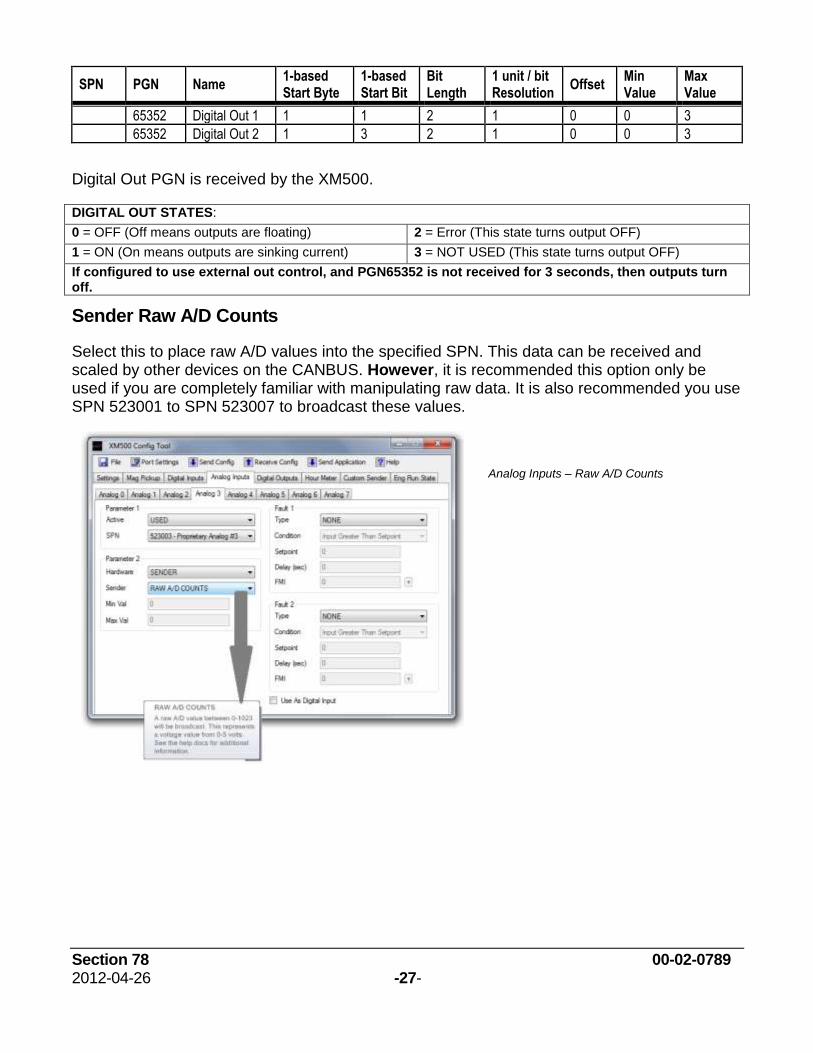
Sender Raw A/D Counts
Select this to place raw A/D values into the specified SPN. This data can be received and scaled by other devices on the CANBUS. However, it is recommended this option only be used if you are completely familiar with manipulating raw data. It is also recommended you use SPN 523001 to SPN 523007 to broadcast these values.
Analog Inputs – Raw A/D Counts
Section 78 00-02-0789 2012-04-26 -28-
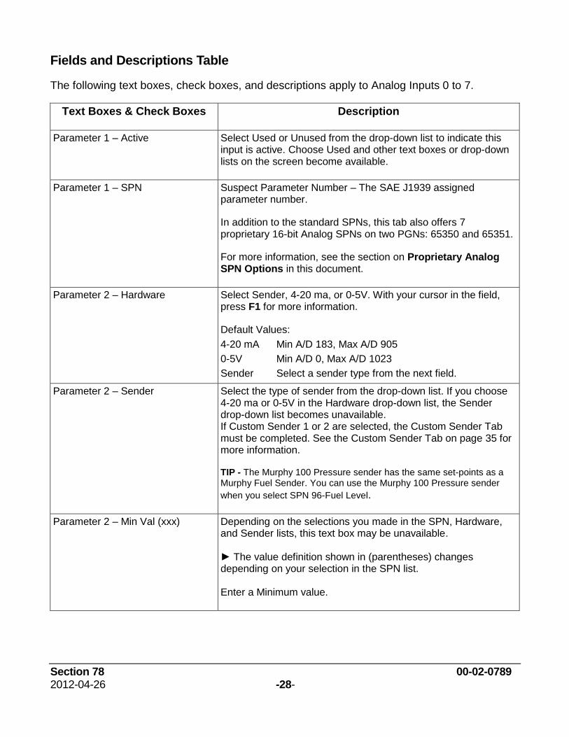
Fields and Descriptions Table
The following text boxes, check boxes, and descriptions apply to Analog Inputs 0 to 7.
Text Boxes & Check Boxes Description
Parameter 1 – Active Select Used or Unused from the drop-down list to indicate this input is active. Choose Used and other text boxes or drop-down lists on the screen become available.
Parameter 1 – SPN Suspect Parameter Number – The SAE J1939 assigned parameter number.
In addition to the standard SPNs, this tab also offers 7 proprietary 16-bit Analog SPNs on two PGNs: 65350 and 65351.
For more information, see the section on Proprietary Analog SPN Options in this document.
Parameter 2 – Hardware Select Sender, 4-20 ma, or 0-5V. With your cursor in the field, press F1 for more information.
Default Values:
4-20 mA Min A/D 183, Max A/D 905
0-5V Min A/D 0, Max A/D 1023
Sender Select a sender type from the next field.
Parameter 2 – Sender Select the type of sender from the drop-down list. If you choose 4-20 ma or 0-5V in the Hardware drop-down list, the Sender drop-down list becomes unavailable. If Custom Sender 1 or 2 are selected, the Custom Sender Tab must be completed. See the Custom Sender Tab on page 35 for more information.
TIP - The Murphy 100 Pressure sender has the same set-points as a Murphy Fuel Sender. You can use the Murphy 100 Pressure sender
when you select SPN 96-Fuel Level.
Parameter 2 – Min Val (xxx) Depending on the selections you made in the SPN, Hardware, and Sender lists, this text box may be unavailable. ► The value definition shown in (parentheses) changes depending on your selection in the SPN list. Enter a Minimum value.
Section 78 00-02-0789 2012-04-26 -29-
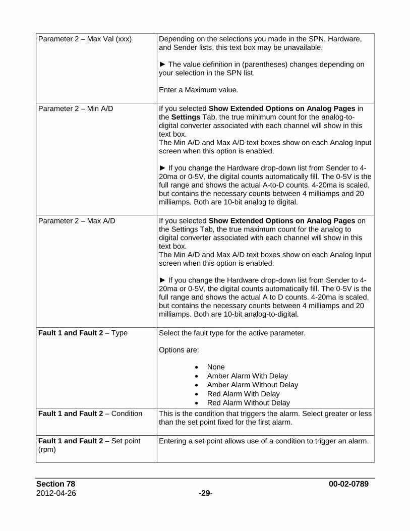
Parameter 2 – Max Val (xxx) Depending on the selections you made in the SPN, Hardware, and Sender lists, this text box may be unavailable. ► The value definition in (parentheses) changes depending on your selection in the SPN list. Enter a Maximum value.
Parameter 2 – Min A/D If you selected Show Extended Options on Analog Pages in the Settings Tab, the true minimum count for the analog-to-digital converter associated with each channel will show in this text box. The Min A/D and Max A/D text boxes show on each Analog Input screen when this option is enabled. ► If you change the Hardware drop-down list from Sender to 4-20ma or 0-5V, the digital counts automatically fill. The 0-5V is the full range and shows the actual A-to-D counts. 4-20ma is scaled, but contains the necessary counts between 4 milliamps and 20 milliamps. Both are 10-bit analog to digital.
Parameter 2 – Max A/D If you selected Show Extended Options on Analog Pages on the Settings Tab, the true maximum count for the analog to digital converter associated with each channel will show in this text box. The Min A/D and Max A/D text boxes show on each Analog Input screen when this option is enabled. ► If you change the Hardware drop-down list from Sender to 4-20ma or 0-5V, the digital counts automatically fill. The 0-5V is the full range and shows the actual A to D counts. 4-20ma is scaled, but contains the necessary counts between 4 milliamps and 20 milliamps. Both are 10-bit analog-to-digital.
Fault 1 and Fault 2 – Type Select the fault type for the active parameter. Options are:
None
Amber Alarm With Delay
Amber Alarm Without Delay
Red Alarm With Delay
Red Alarm Without Delay
Fault 1 and Fault 2 ‒ Condition This is the condition that triggers the alarm. Select greater or less than the set point fixed for the first alarm.
Fault 1 and Fault 2 – Set point (rpm)
Entering a set point allows use of a condition to trigger an alarm.
Section 78 00-02-0789 2012-04-26 -30-
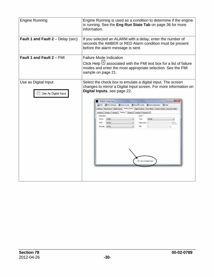
Engine Running Engine Running is used as a condition to determine if the engine is running. See the Eng Run State Tab on page 36 for more information.
Fault 1 and Fault 2 – Delay (sec) If you selected an ALARM with a delay, enter the number of seconds the AMBER or RED Alarm condition must be present before the alarm message is sent.
Fault 1 and Fault 2 ‒ FMI Failure Mode Indication
Click Help associated with the FMI text box for a list of failure modes and enter the most appropriate selection. See the FMI sample on page 21.
Use as Digital Input
Select the check box to emulate a digital input. The screen changes to mirror a Digital Input screen. For more information on Digital Inputs, see page 22.
Section 78 00-02-0789 2012-04-26 -31-
Digital Outputs Tab
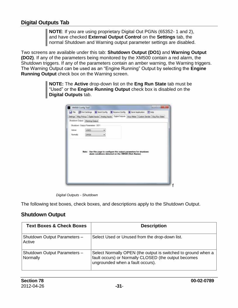
NOTE: If you are using proprietary Digital Out PGNs (65352- 1 and 2), and have checked External Output Control on the Settings tab, the normal Shutdown and Warning output parameter settings are disabled.
Two screens are available under this tab: Shutdown Output (DO1) and Warning Output (DO2). If any of the parameters being monitored by the XM500 contain a red alarm, the Shutdown triggers. If any of the parameters contain an amber warning, the Warning triggers. The Warning Output can be used as an “Engine Running” Output by selecting the Engine Running Output check box on the Warning screen.
NOTE: The Active drop-down list on the Eng Run State tab must be “Used” or the Engine Running Output check box is disabled on the Digital Outputs tab.
f
Digital Outputs - Shutdown
The following text boxes, check boxes, and descriptions apply to the Shutdown Output.
Shutdown Output
Text Boxes & Check Boxes Description
Shutdown Output Parameters – Active
Select Used or Unused from the drop-down list.
Shutdown Output Parameters – Normally
Select Normally OPEN (the output is switched to ground when a fault occurs) or Normally CLOSED (the output becomes ungrounded when a fault occurs).
Section 78 00-02-0789 2012-04-26 -32-
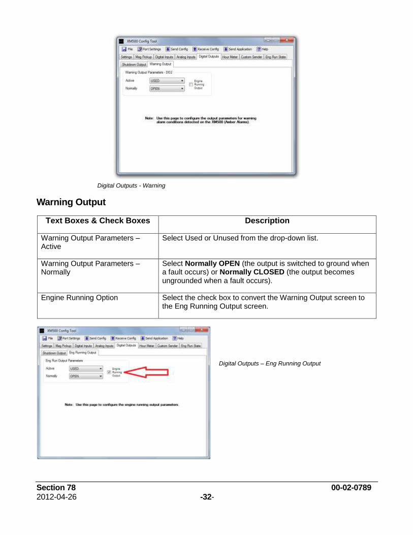
Digital Outputs - Warning
Warning Output
Text Boxes & Check Boxes Description
Warning Output Parameters – Active
Select Used or Unused from the drop-down list.
Warning Output Parameters – Normally
Select Normally OPEN (the output is switched to ground when a fault occurs) or Normally CLOSED (the output becomes ungrounded when a fault occurs).
Engine Running Option Select the check box to convert the Warning Output screen to the Eng Running Output screen.
Digital Outputs – Eng Running Output
Section 78 00-02-0789 2012-04-26 -33-
Eng Running Output
Text & Check Boxes Description
Warning Output Parameters – Active
Select Used or Unused from the drop-down list.
Warning Output Parameters – Normally
Select Normally OPEN (the output is switched to ground when a fault occurs) or Normally CLOSED (the output becomes ungrounded when a fault occurs).
Engine Running Option Clear the check box to convert the Eng Running Output screen to the Warning Output screen.
Section 78 00-02-0789 2012-04-26 -34-
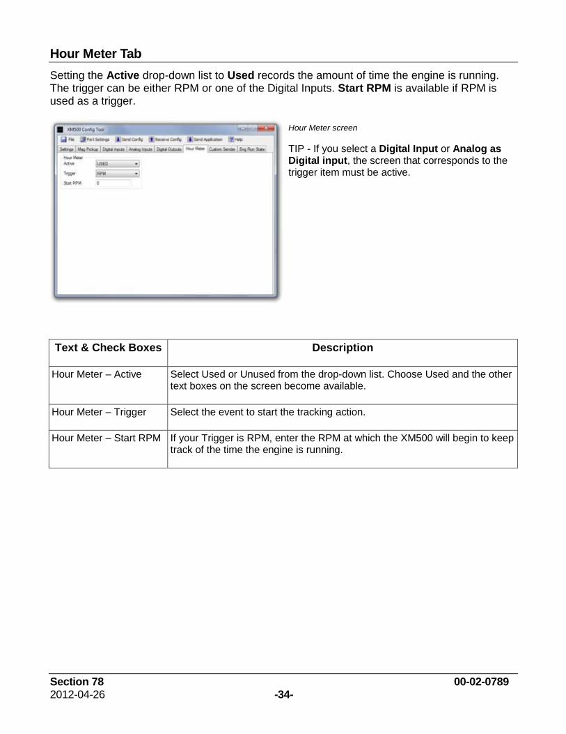
Hour Meter Tab
Setting the Active drop-down list to Used records the amount of time the engine is running. The trigger can be either RPM or one of the Digital Inputs. Start RPM is available if RPM is used as a trigger.
Hour Meter screen
TIP - If you select a Digital Input or Analog as Digital input, the screen that corresponds to the trigger item must be active.
Text & Check Boxes Description
Hour Meter – Active Select Used or Unused from the drop-down list. Choose Used and the other text boxes on the screen become available.
Hour Meter – Trigger Select the event to start the tracking action.
Hour Meter – Start RPM If your Trigger is RPM, enter the RPM at which the XM500 will begin to keep track of the time the engine is running.
Section 78 00-02-0789 2012-04-26 -35-
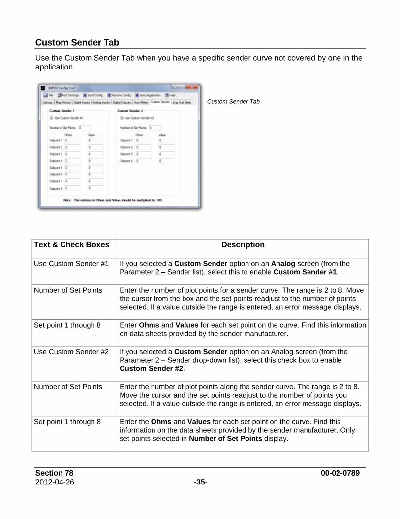
Custom Sender Tab
Use the Custom Sender Tab when you have a specific sender curve not covered by one in the application.
Custom Sender Tab
Text & Check Boxes Description
Use Custom Sender #1 If you selected a Custom Sender option on an Analog screen (from the Parameter 2 – Sender list), select this to enable Custom Sender #1.
Number of Set Points Enter the number of plot points for a sender curve. The range is 2 to 8. Move the cursor from the box and the set points readjust to the number of points selected. If a value outside the range is entered, an error message displays.
Set point 1 through 8 Enter Ohms and Values for each set point on the curve. Find this information on data sheets provided by the sender manufacturer.
Use Custom Sender #2 If you selected a Custom Sender option on an Analog screen (from the Parameter 2 – Sender drop-down list), select this check box to enable Custom Sender #2.
Number of Set Points Enter the number of plot points along the sender curve. The range is 2 to 8. Move the cursor and the set points readjust to the number of points you selected. If a value outside the range is entered, an error message displays.
Set point 1 through 8 Enter the Ohms and Values for each set point on the curve. Find this information on the data sheets provided by the sender manufacturer. Only set points selected in Number of Set Points display.
Section 78 00-02-0789 2012-04-26 -36-
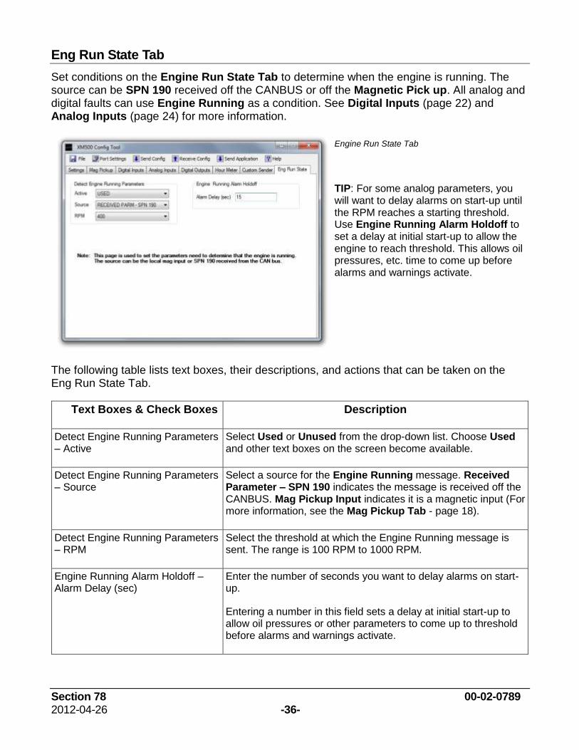
Eng Run State Tab
Set conditions on the Engine Run State Tab to determine when the engine is running. The source can be SPN 190 received off the CANBUS or off the Magnetic Pick up. All analog and digital faults can use Engine Running as a condition. See Digital Inputs (page 22) and Analog Inputs (page 24) for more information.
Engine Run State Tab
TIP: For some analog parameters, you will want to delay alarms on start-up until the RPM reaches a starting threshold. Use Engine Running Alarm Holdoff to set a delay at initial start-up to allow the engine to reach threshold. This allows oil pressures, etc. time to come up before alarms and warnings activate.
The following table lists text boxes, their descriptions, and actions that can be taken on the Eng Run State Tab.
Text Boxes & Check Boxes Description
Detect Engine Running Parameters – Active
Select Used or Unused from the drop-down list. Choose Used and other text boxes on the screen become available.
Detect Engine Running Parameters – Source
Select a source for the Engine Running message. Received Parameter – SPN 190 indicates the message is received off the CANBUS. Mag Pickup Input indicates it is a magnetic input (For more information, see the Mag Pickup Tab - page 18).
Detect Engine Running Parameters – RPM
Select the threshold at which the Engine Running message is sent. The range is 100 RPM to 1000 RPM.
Engine Running Alarm Holdoff – Alarm Delay (sec)
Enter the number of seconds you want to delay alarms on start-up.
Entering a number in this field sets a delay at initial start-up to allow oil pressures or other parameters to come up to threshold before alarms and warnings activate.
Section 78 00-02-0789 2012-04-26 -37-
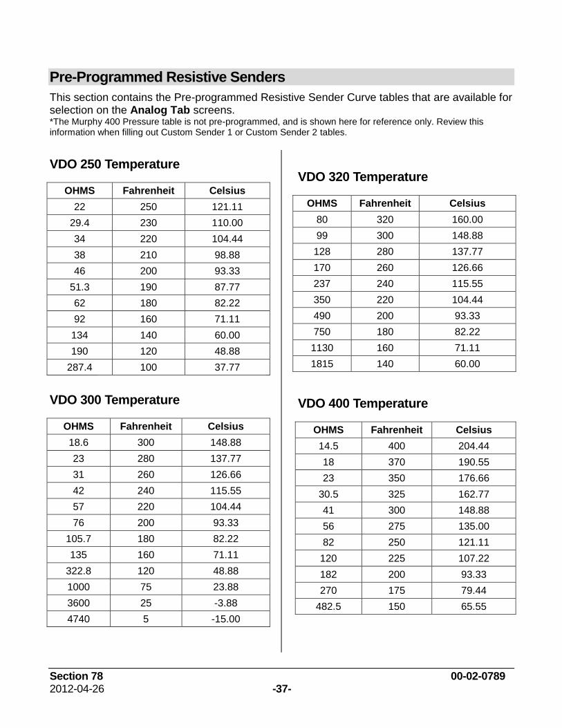
Pre-Programmed Resistive Senders
This section contains the Pre-programmed Resistive Sender Curve tables that are available for selection on the Analog Tab screens. *The Murphy 400 Pressure table is not pre-programmed, and is shown here for reference only. Review this information when filling out Custom Sender 1 or Custom Sender 2 tables.
VDO 250 Temperature
OHMS Fahrenheit Celsius
22 250 121.11
29.4 230 110.00
34 220 104.44
38 210 98.88
46 200 93.33
51.3 190 87.77
62 180 82.22
92 160 71.11
134 140 60.00
190 120 48.88
287.4 100 37.77
VDO 300 Temperature
OHMS Fahrenheit Celsius
18.6 300 148.88
23 280 137.77
31 260 126.66
42 240 115.55
57 220 104.44
76 200 93.33
105.7 180 82.22
135 160 71.11
322.8 120 48.88
1000 75 23.88
3600 25 -3.88
4740 5 -15.00
VDO 320 Temperature
OHMS Fahrenheit Celsius
80 320 160.00
99 300 148.88
128 280 137.77
170 260 126.66
237 240 115.55
350 220 104.44
490 200 93.33
750 180 82.22
1130 160 71.11
1815 140 60.00
VDO 400 Temperature
OHMS Fahrenheit Celsius
14.5 400 204.44
18 370 190.55
23 350 176.66
30.5 325 162.77
41 300 148.88
56 275 135.00
82 250 121.11
120 225 107.22
182 200 93.33
270 175 79.44
482.5 150 65.55
Section 78 00-02-0789 2012-04-26 -38-
VDO 30 Pressure
OHMS PSI KPA
7.5 0 0
45 5 34.47
70 10 68.94
100 15 103.42
128 20 137.89
164 25 172.36
195 30 206.84
VDO 80 Pressure
OHMS PSI KPA
10 0 0
36 10 68.94
61 20 137.89
84 30 206.84
108 40 275.79
132 50 344.73
156 60 413.68
179 70 482.63
192 80 551.58
VDO 100 Pressure
OHMS PSI KPA
10 0 0
34 10 68.95
52 20 137.90
69 30 206.84
84 40 275.79
97 50 344.74
108 60 413.69
121 70 482.63
137 80 551.58
155 90 620.53
180 100 689.48
VDO 150 Pressure
OHMS PSI KPA
10 0 0
26 10 68.95
40 20 137.90
53 30 206.84
67 40 275.79
78 50 344.74
90.5 60 413.69
103 70 482.63
115 80 551.58
127 90 620.53
138 100 689.48
149 110 758.42
160 120 827.37
178 140 896.32
189.5 150 965.27
VDO 400 Pressure
OHMS PSI KPA
10 0 0
36 50 344.73
66 100 689.47
82 150 1034.21
103 200 1378.95
125 250 1723.68
141 300 2068.42
161 350 2413.16
184 400 2757.90
Section 78 00-02-0789 2012-04-26 -39-
MURPHY 100 Pressure/Fuel Level
OHMS PSI KPA
33 100 689.48
47 90 620.53
60 80 551.58
74 70 482.63
88 60 413.69
103 50 344.74
123 40 275.79
143 30 206.84
171 20 137.90
205 10 68.95
240 0 0
MURPHY 300 Temperature
OHMS Fahrenheit Celsius
25.3 300 148.88
40 284 140.00
52 266 130.00
74 248 120.00
89 230 110.00
120 212 100.00
164 194 90.00
227 176 80.00
321 158 70.00
680 122 50.00
1029 104 40.00
1594 86 30.00
3127 60 15.55
7833.7 30 -1.11
14425 5 -17.75
MURPHY 30 Pressure
OHMS PSI KPA
10 0 0
92 1 6.90
36.6 5 34.47
64 10 68.95
91 15 103.42
120 20 137.90
146.5 25 172.37
180 30 206.54
MURPHY 400 Pressure (for reference only)
OHMS PSI KPA
33 400 2758
47 360 2482
60 320 2206
88 240 1655
103 200 1379
143 100 827
171 80 552
240 0 0
YANMAR 114 Pressure
OHMS PSI KPA
12 114 786.00
43 57 393.00
83 0 0
YANMAR 100 Temperature
OHMS VAL(F) VAL(C)
63.5 212 100
170 158 70
350 122 50
770 86 30
1000 32 0
Section 78 00-02-0789 2012-04-26 -40-
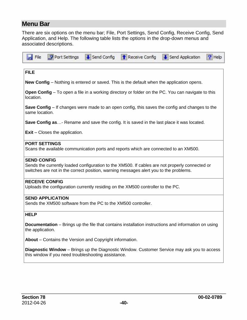
Menu Bar
There are six options on the menu bar; File, Port Settings, Send Config, Receive Config, Send Application, and Help. The following table lists the options in the drop-down menus and associated descriptions.
FILE
New Config – Nothing is entered or saved. This is the default when the application opens.
Open Config – To open a file in a working directory or folder on the PC. You can navigate to this location.
Save Config – If changes were made to an open config, this saves the config and changes to the same location.
Save Config as…- Rename and save the config. It is saved in the last place it was located.
Exit – Closes the application.
PORT SETTINGS Scans the available communication ports and reports which are connected to an XM500.
SEND CONFIG Sends the currently loaded configuration to the XM500. If cables are not properly connected or switches are not in the correct position, warning messages alert you to the problems.
RECEIVE CONFIG Uploads the configuration currently residing on the XM500 controller to the PC.
SEND APPLICATION Sends the XM500 software from the PC to the XM500 controller.
HELP
Documentation – Brings up the file that contains installation instructions and information on using the application.
About – Contains the Version and Copyright information.
Diagnostic Window – Brings up the Diagnostic Window. Customer Service may ask you to access this window if you need troubleshooting assistance.
Section 78 00-02-0789 2012-04-26 -41-
Wiring Diagram Example