Embed Size (px)
Citation preview
1
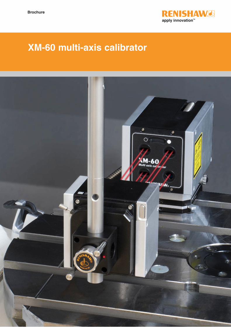
XM-60 multi axis calibratorXM-60 multi-axis calibrator
Brochure
2
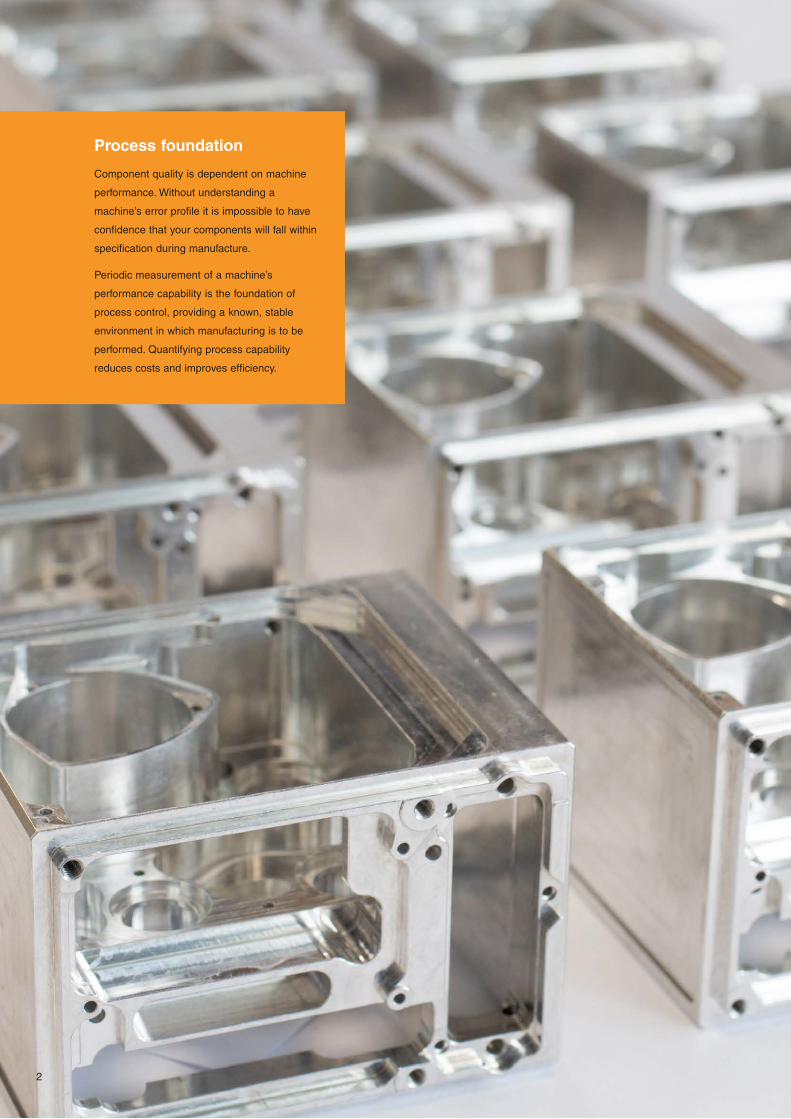
Process foundation
Component quality is dependent on machine
performance. Without understanding a
machine’s error profile it is impossible to have
confidence that your components will fall within
specification during manufacture.
Periodic measurement of a machine’s
performance capability is the foundation of
process control, providing a known, stable
environment in which manufacturing is to be
performed. Quantifying process capability
reduces costs and improves efficiency.
3
Why do you need an XM-60 multi-axis calibrator?
The machine tool industry is developing quickly. Initiatives to improve efficiency, and reduce scrap and production costs have
created the need to understand manufacturing processes better than ever before. Knowing the capability of machine tools
before metal cutting is the foundation of any machining process.
Laser interferometry, the globally recognised approach for machine calibration, offers the ultimate in accuracy. However,
measuring one error per set-up is time consuming for users who wish to measure more than linear errors. With complex
machine structures and more intricate components being manufactured, measuring linear performance alone is not enough.
Frictional effects and other faults in the axis construction can cause the axis to rotate as it moves, creating a difference
between the indicated and actual positions of machine elements. These ‘angular’ and ‘straightness’ effects can cause significant
feature position errors, or profile and surface deviation, resulting in out-of-tolerance components.
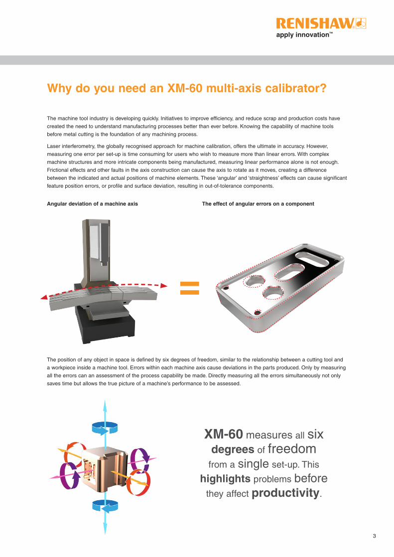
The position of any object in space is defined by six degrees of freedom, similar to the relationship between a cutting tool and
a workpiece inside a machine tool. Errors within each machine axis cause deviations in the parts produced. Only by measuring
all the errors can an assessment of the process capability be made. Directly measuring all the errors simultaneously not only
saves time but allows the true picture of a machine’s performance to be assessed.
XM-60 measures all six
degrees of freedom
from a single set-up. This
highlights problems before
they affect productivity.
Angular deviation of a machine axis The effect of angular errors on a component
4
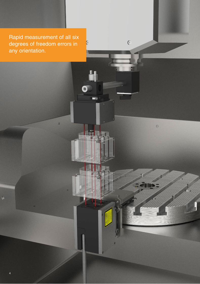
Rapid measurement of all six degrees of freedom errors in any orientation.

5
Direct measurement of errors
XM-60 provides users with powerful machine diagnostic capability through the measurement of all degrees of freedom from a
‘single shot’. By capturing six degrees of freedom, users can discover the source of their errors, rather than the effect which is
often seen when performing linear measurement alone.
Reducing measurement uncertainties is important for any user. The XM-60 has been designed to measure machine errors
directly, by aligning the laser beams with a machine axis. This reduces the inaccuracies which can result from complex
mathematics used in alternative measurement techniques. Direct measurement makes comparison before and after machine
adjustments a quick and simple task.
Operation in any orientation
The pure optical system in the XM-60 allows operation in any orientation. The launch unit can be mounted on its side, upside
down and on its back, useful for vertical axis testing, slant-bed lathes and more complex machine structures.
Reducing measurement uncertainties is important for any user
6
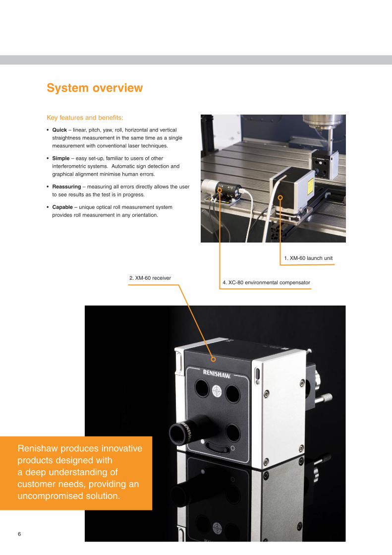
1. XM-60 launch unit
System overview
Key features and benefits:
• Quick – linear, pitch, yaw, roll, horizontal and vertical
straightness measurement in the same time as a single
measurement with conventional laser techniques.
• Simple – easy set-up, familiar to users of other
interferometric systems. Automatic sign detection and
graphical alignment minimise human errors.
• Reassuring – measuring all errors directly allows the user
to see results as the test is in progress.
• Capable – unique optical roll measurement system
provides roll measurement in any orientation.
4. XC-80 environmental compensator
Renishaw produces innovative products designed with a deep understanding of customer needs, providing an uncompromised solution.
2. XM-60 receiver

7
1. Laser / launch unit
• Flexible – a separate laser unit enables the use of a
remote compact fibre optic launch unit. This gives more
flexible mounting options and minimises the impact on
measurement volume.
• Thermal stability – the laser heat source is located
outside the machine environment. The use of an external
laser source reduces thermal effects on the measurement
optics and on the machine under test.
2. Receiver
• Wireless communication – the roll and straightness data
is communicated wirelessly back to the laser unit via an
integrated wireless connection.
• No cables – powered by rechargeable batteries avoiding
trailing cables during machine moves.
• Lightweight – designed to minimise the load on the
machine spindle.
3. CARTO software suite
• Intuitive – guides the user through the workflow of
the measurement process. The Capture and Explore
applications provide data capture and analysis for
XM-60.
4. XC-80 environmental compensator
• Reliable – XC-80 environmental compensator minimises
the effect of the operating environment.
• Accurate – maintains full measurement accuracy
from 0 °C – 40 °C.
5. System case
• Portable – robust Peli™ storm system case designed
to provide safe storage and transportation of the
laser system, with space for accessories and XC-80
compensator kit.
1. Laser unit
3. CARTO software suite

Precise measurement capability requires meticulous assembly techniques
8

9
Precision engineered
Engineered by Renishaw
Renishaw laser measurement systems are manufactured to
provide high performance and long operational lives.
The aluminium substructure provides lightweight yet strong
construction, designed to give the smallest package to fit
onto machine tools. The combined weight of the launch and
receiver is only 2.5 kg.
Thermal design
The XM-60 employs thermal breaks between the magnetic
mount and the product housing. This ensures changes in
machine thermals do not affect the device and temperature
variation in the XM-60 does not affect machine performance.
Roll detection
The XM-60 provides a highly accurate laser system that
incorporates unique technology with a patented optical roll
measurement and fibre optic launch system. The compact
launch unit is remote from the laser unit, reducing heat
effects at the point of measurement. It can be mounted
directly to the machine on its side, upside down and even on
its back, which is particularly beneficial in areas with difficult
machine access.
10
Precision engineered
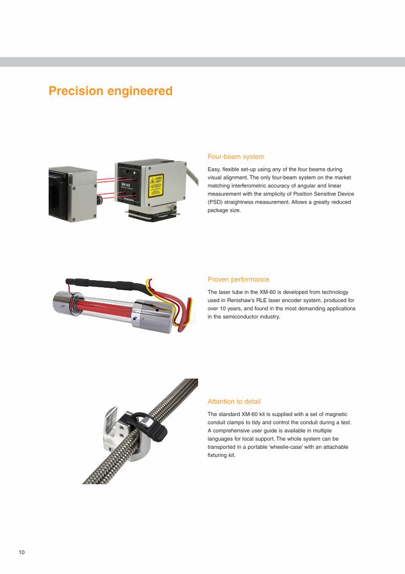
Four-beam system
Easy, flexible set-up using any of the four beams during
visual alignment. The only four-beam system on the market
matching interferometric accuracy of angular and linear
measurement with the simplicity of Position Sensitive Device
(PSD) straightness measurement. Allows a greatly reduced
package size.
Proven performance
The laser tube in the XM-60 is developed from technology
used in Renishaw’s RLE laser encoder system, produced for
over 10 years, and found in the most demanding applications
in the semiconductor industry.
Attention to detail
The standard XM-60 kit is supplied with a set of magnetic
conduit clamps to tidy and control the conduit during a test.
A comprehensive user guide is available in multiple
languages for local support. The whole system can be
transported in a portable ‘wheelie-case’ with an attachable
fixturing kit.
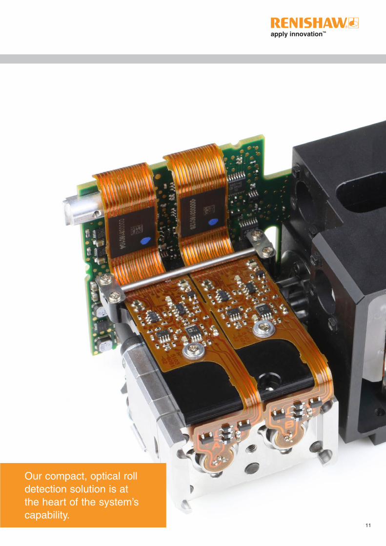
Our compact, optical roll detection solution is at the heart of the system’s capability.
11
12
13
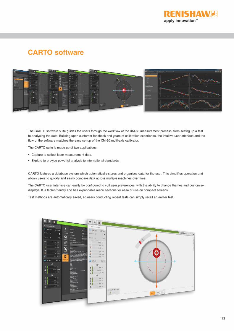
CARTO software
The CARTO software suite guides the users through the workflow of the XM-60 measurement process, from setting up a test
to analysing the data. Building upon customer feedback and years of calibration experience, the intuitive user interface and the
flow of the software matches the easy set-up of the XM-60 multi-axis calibrator.
The CARTO suite is made up of two applications;
• Capture to collect laser measurement data.
• Explore to provide powerful analysis to international standards.
CARTO features a database system which automatically stores and organises data for the user. This simplifies operation and
allows users to quickly and easily compare data across multiple machines over time.
The CARTO user interface can easily be configured to suit user preferences, with the ability to change themes and customise
displays. It is tablet-friendly and has expandable menu sections for ease of use on compact screens.
Test methods are automatically saved, so users conducting repeat tests can simply recall an earlier test.

14
Capture Guides the user step-by-step through the data capture process
Software that thinks for the user
When a new test method is created, CARTO can provide defaults from previous set-ups. Fields such as dwell time are
automatically populated based on the averaging that the user has chosen, saving the user test and set-up time.
Automatic triggering for all channels
Always having a linear position channel with XM-60 enables automatic triggering for all tests, even if the user is only interested
in the angular measurement. There is never the need to manually trigger the laser.
Elegant, simple alignment
The straightness measurement from XM-60 is also used to align the system. CARTO graphically displays the alignment of the
system making set-up simple and easy to understand.
Part program generation
Capture features a part program generator, supporting Fanuc 30, Heidenhain 530, Mazak Matrix and Siemens 840D
controllers, with more to follow.
‘Free-run mode’
Allows users to capture data immediately, without having to define the positions, or even the number of targets. The software
displays straightness (horizontal and vertical), pitch, yaw and roll errors against linear position. Triggering can be manual
(with a keypress), automatic (based on stability of position) or continuous (captured during motion at a user-defined interval).

15
Analysis standards
Different companies need to comply with different standards, therefore each measurement (linear, pitch, yaw, roll and
straightness) can be displayed with all supported analysis standards. To make it easier for the user, these can also be sorted,
enabled or hidden from view.
Tagging
As the analysis browser fills up with a large quantity of tests, finding the data you need can take time. Explore has made this
simple by allowing the user to assign a tag to any test saved in the database. All the data can then be filtered by a tag or
multiple tags.
Compare
Even after a report has been printed, we don’t stop there. Explore features a handy comparison tool, allowing users to look
through the history of their test records and see the effect that numerous factors have on six channels of error.
Error compensation
Create linear error compensation files to improve machine performance. Error plots from before and after compensation can be
added to a comparison graph to verify the improved machine performance.
Import files
Easily import legacy files to the database using the file importer function.
Explore Rapid analysis and reporting of results
16
17
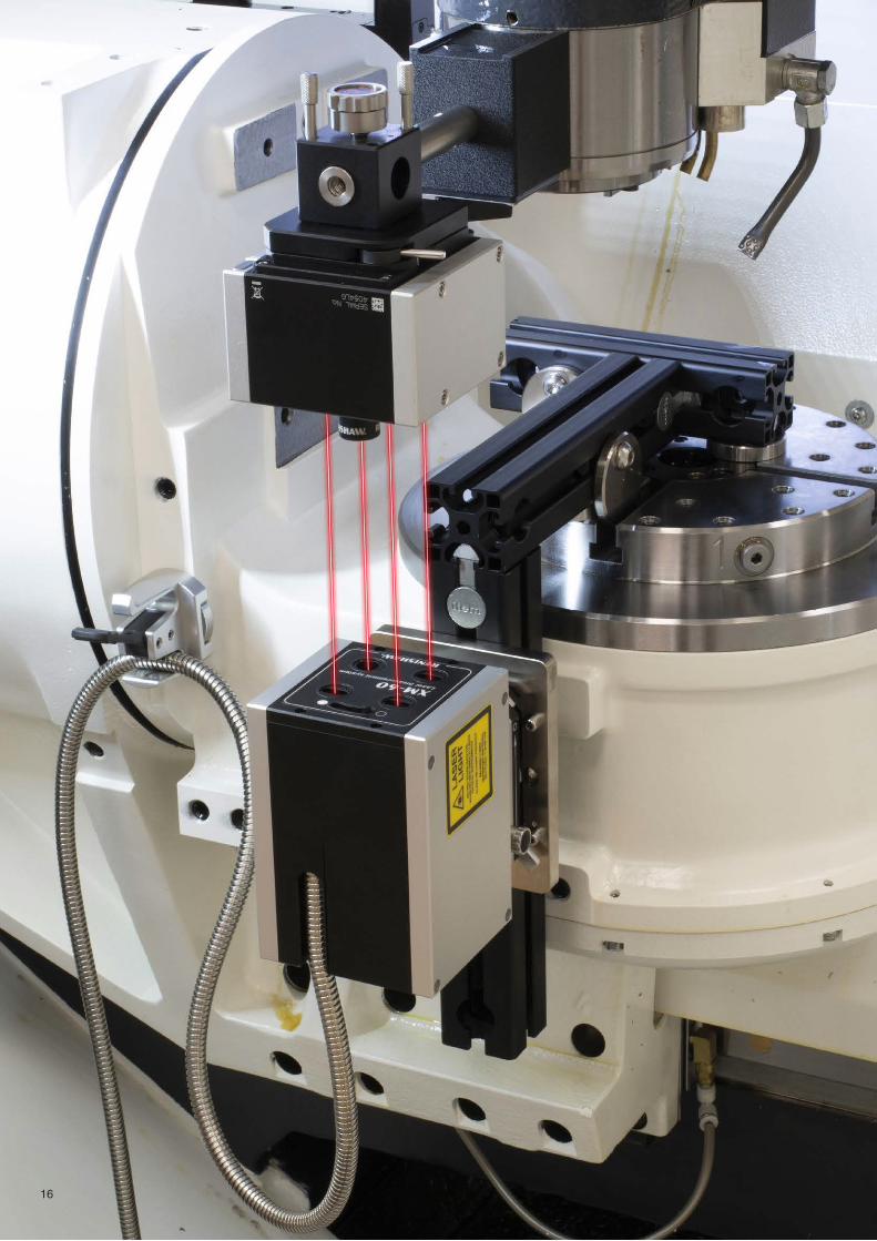
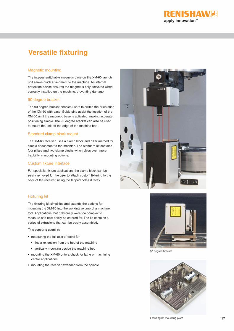
Magnetic mounting
The integral switchable magnetic base on the XM-60 launch
unit allows quick attachment to the machine. An internal
protection device ensures the magnet is only activated when
correctly installed on the machine, preventing damage.
90 degree bracket
The 90 degree bracket enables users to switch the orientation
of the XM-60 with ease. Guide pins assist the location of the
XM-60 until the magnetic base is activated, making accurate
positioning simple. The 90 degree bracket can also be used
to mount the unit off the edge of the machine bed.
Standard clamp block mount
The XM-60 receiver uses a clamp block and pillar method for
simple attachment to the machine. The standard kit contains
four pillars and two clamp blocks which gives even more
flexibility in mounting options.
Custom fixture interface
For specialist fixture applications the clamp block can be
easily removed for the user to attach custom fixturing to the
back of the receiver, using the tapped holes directly.
Fixturing kit
The fixturing kit simplifies and extends the options for
mounting the XM-60 into the working volume of a machine
tool. Applications that previously were too complex to
measure can now easily be catered for. The kit contains a
series of extrusions that can be easily assembled.
This supports users in:
• measuring the full axis of travel for:
• linear extension from the bed of the machine
• vertically mounting beside the machine bed
• mounting the XM-60 onto a chuck for lathe or machining
centre applications
• mounting the receiver extended from the spindle
Versatile fixturing
90 degree bracket
Fixturing kit mounting plate

18
Service and quality
Training
Renishaw offers an established range of comprehensive operator
training courses either on-site or at a Renishaw training centre.
Our experience in metrology allows us to teach not just about our
products, but also underlying scientific principles and methods of
best practice.
This enables our customers to get the most out of their
manufacturing processes.
Certification
Renishaw plc is certified and audited regularly to the latest ISO 9001 quality
assurance standard. This ensures all aspects of design, manufacture, sales, after
sales support, and recalibration remain at the highest standards.
The certificate is issued by BSI Management Systems, an internationally recognised
certification body, accredited by UKAS.
Our ongoing commitment to service and quality provides our customers with the complete solution

19
Support
Our products enhance quality and productivity, and we strive for total customer satisfaction through superior customer service
and expert knowledge of potential product applications. When you purchase a laser or ballbar system from Renishaw, you are
buying into a worldwide support network that understands machine metrology and the service of production equipment.
Renishaw calibrations in the UK are traceable to the National Physical Laboratory, a signatory of the CIPM MRA. Calibration
facilities worldwide can provide local laser calibration traceability.
Design and build
Not only does Renishaw have comprehensive in-house design capability, its extensive manufacturing capacity allows it to
produce nearly all components and assemblies in-house. This gives us the ability to fully understand and control our design
and build process.
The performance of Renishaw lasers has been independently verified by the National Physical Laboratory (UK) and the
Physikalisch-Technische Bundesanstalt (Germany).
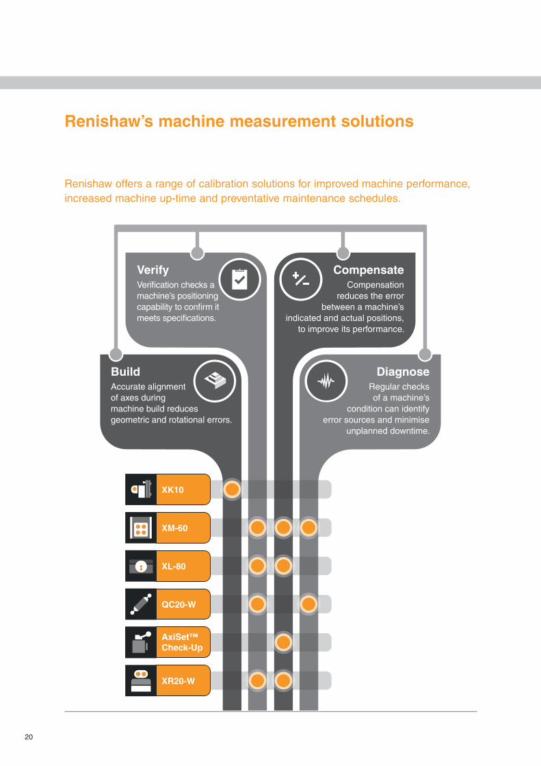
20
Renishaw offers a range of calibration solutions for improved machine performance, increased machine up-time and preventative maintenance schedules.
Renishaw’s machine measurement solutions
BuildAccurate alignment of axes during machine build reduces geometric and rotational errors.
VerifyVerification checks a machine’s positioning capability to confirm it meets specifications.
CompensateCompensation
reduces the error between a machine’s
indicated and actual positions, to improve its performance.
DiagnoseRegular checks of a machine’s
condition can identify error sources and minimise
unplanned downtime.
Introducing Renishaw’s machine measurement solutions Renishaw offers a range of calibration solutions for
improved machine performance, increased machine up-time and preventative maintenance schedules.
XK10
XM-60
XL-80
QC20-W
AxiSet™Check-Up
XR20-W
20
21
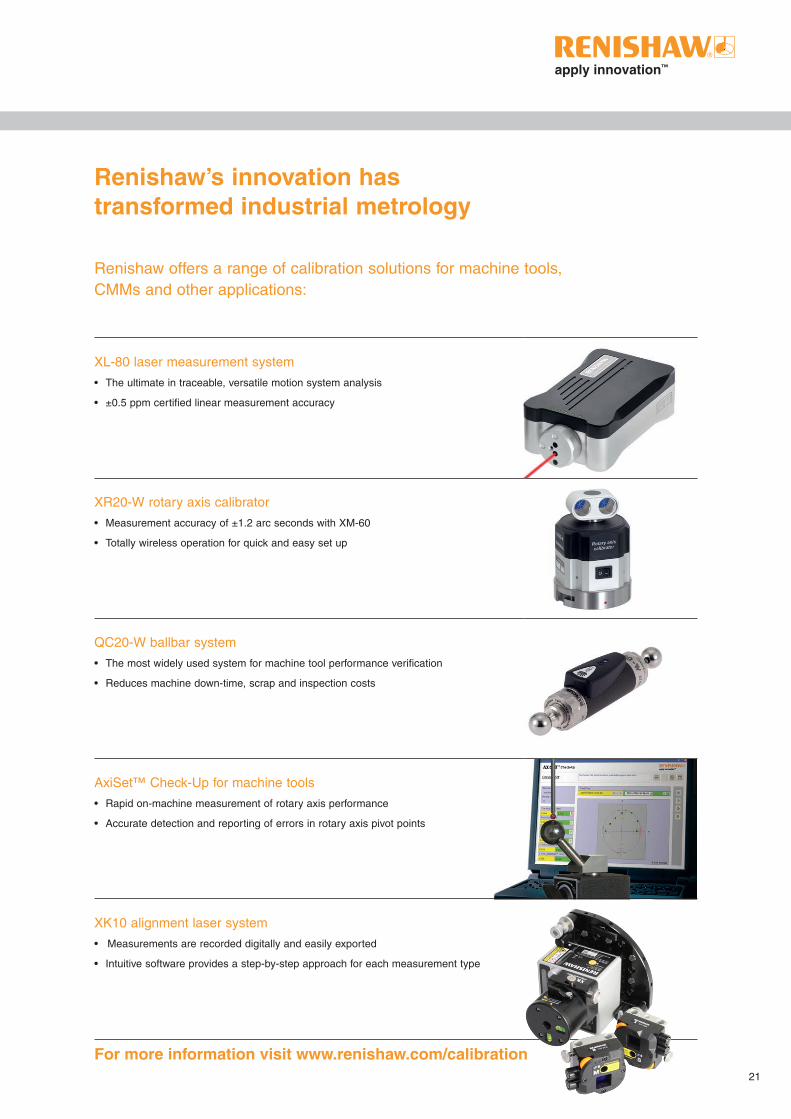
Renishaw’s innovation has transformed industrial metrology
Renishaw offers a range of calibration solutions for machine tools, CMMs and other applications:
XL-80 laser measurement system
• The ultimate in traceable, versatile motion system analysis
• ±0.5 ppm certified linear measurement accuracy
XR20-W rotary axis calibrator
• Measurement accuracy of ±1.2 arc seconds with XM-60
• Totally wireless operation for quick and easy set up
QC20-W ballbar system
• The most widely used system for machine tool performance verification
• Reduces machine down-time, scrap and inspection costs
AxiSet™ Check-Up for machine tools
• Rapid on-machine measurement of rotary axis performance
• Accurate detection and reporting of errors in rotary axis pivot points
XK10 alignment laser system
• Measurements are recorded digitally and easily exported
• Intuitive software provides a step-by-step approach for each measurement type
For more information visit www.renishaw.com/calibration

22 XM-60 with XR20-W rotary axis calibrator
23
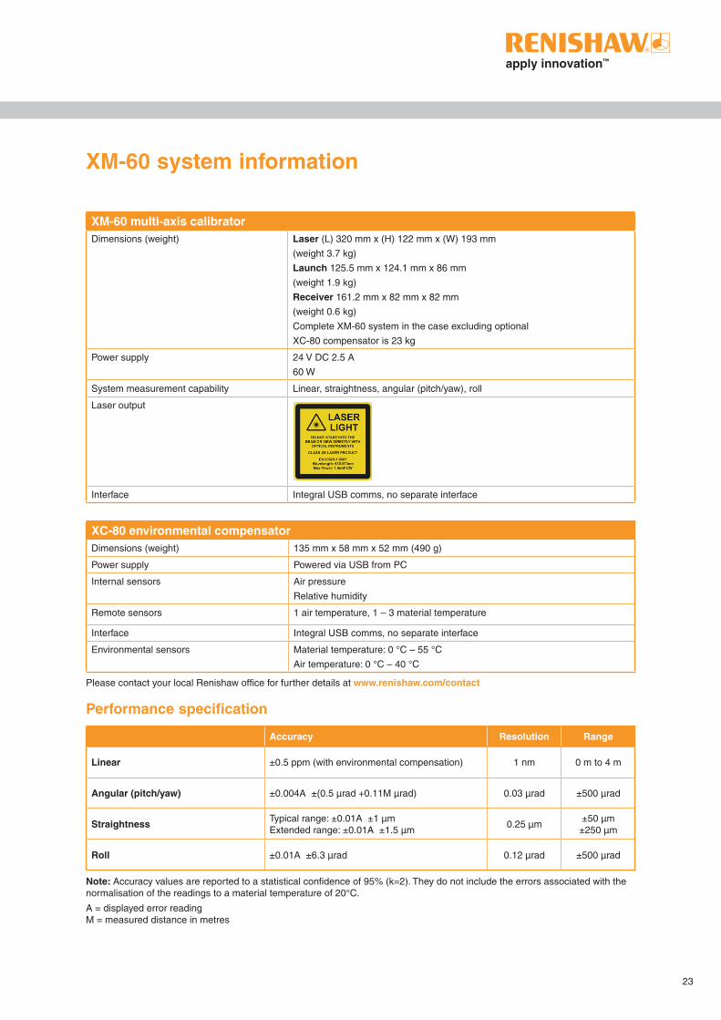
XC-80 environmental compensatorDimensions (weight) 135 mm x 58 mm x 52 mm (490 g)
Power supply Powered via USB from PC
Internal sensors Air pressure
Relative humidity
Remote sensors 1 air temperature, 1 – 3 material temperature
Interface Integral USB comms, no separate interface
Environmental sensors Material temperature: 0 °C – 55 °C
Air temperature: 0 °C – 40 °C
Please contact your local Renishaw office for further details at www.renishaw.com/contact
XM-60 multi-axis calibratorDimensions (weight) Laser (L) 320 mm x (H) 122 mm x (W) 193 mm
(weight 3.7 kg)
Launch 125.5 mm x 124.1 mm x 86 mm
(weight 1.9 kg)
Receiver 161.2 mm x 82 mm x 82 mm
(weight 0.6 kg)
Complete XM-60 system in the case excluding optional
XC-80 compensator is 23 kg
Power supply 24 V DC 2.5 A
60 W
System measurement capability Linear, straightness, angular (pitch/yaw), roll
Laser output
Interface Integral USB comms, no separate interface
XM-60 system information
Performance specification
Accuracy Resolution Range
Linear ±0.5 ppm (with environmental compensation) 1 nm 0 m to 4 m
Angular (pitch/yaw) ±0.004A ±(0.5 μrad +0.11M μrad) 0.03 μrad ±500 µrad
Straightness Typical range: ±0.01A ±1 μm Extended range: ±0.01A ±1.5 μm
0.25 μm±50 µm ±250 µm
Roll ±0.01A ±6.3 μrad 0.12 μrad ±500 µrad
Note: Accuracy values are reported to a statistical confidence of 95% (k=2). They do not include the errors associated with the normalisation of the readings to a material temperature of 20°C.
A = displayed error reading M = measured distance in metres

RENISHAW HAS MADE CONSIDERABLE EFFORTS TO ENSURE THE CONTENT OF THIS DOCUMENT IS CORRECT AT THE DATE OF PUBLICATION BUT MAKES NO WARRANTIES OR REPRESENTATIONS REGARDING THE CONTENT. RENISHAW EXCLUDES LIABILITY, HOWSOEVER ARISING, FOR ANY INACCURACIES IN THIS DOCUMENT.
© 2019 Renishaw plc. All rights reserved. Renishaw reserves the right to change specifications without notice.RENISHAW and the probe symbol used in the RENISHAW logo are registered trade marks of Renishaw plc in the United Kingdom and other countries. apply innovation and names and designations of other Renishaw products and technologies are trade marks of Renishaw plc or its subsidiaries.All other brand names and product names used in this document are trade names, trade marks or registered trade marks of their respective owners.
About Renishaw
Renishaw is an established world leader in engineering technologies, with a strong history of innovation in product development and manufacturing. Since its formation in 1973, the company has supplied leading-edge products that increase process productivity, improve product quality and deliver cost-effective automation solutions.
A worldwide network of subsidiary companies and distributors provides exceptional service and support for its customers.
Products include:
• Additive manufacturing and vacuum casting technologies for design, prototyping, and production applications
• Dental CAD/CAM scanning systems and supply of dental structures
• Encoder systems for high-accuracy linear, angle and rotary position feedback
• Fixturing for CMMs (co-ordinate measuring machines) and gauging systems
• Gauging systems for comparative measurement of machined parts
• High-speed laser measurement and surveying systems for use in extreme environments
• Laser and ballbar systems for performance measurement and calibration of machines
• Medical devices for neurosurgical applications
• Probe systems and software for job set-up, tool setting and inspection on CNC machine tools
• Raman spectroscopy systems for non-destructive material analysis
• Sensor systems and software for measurement on CMMs
• Styli for CMM and machine tool probe applications
For worldwide contact details, visit www.renishaw.com/contact
Part no: L-5103-4038-02-CIssued: 10.2019
*L-5103-4038-02-C
T +44 (0) 1453 524524F +44 (0) 1453 524901E [email protected]
www.renishaw.com
Renishaw plc
New Mills, Wotton-under-EdgeGloucestershire, GL12 8JRUnited Kingdom