Embed Size (px)
Citation preview

User GuideFirmware Revision 5
1440-VST02-01RA
XM-120 Eccentricity Module
Important User InformationSolid state equipment has operational characteristics differing from those of electromechanical equipment. Safety Guidelines for the Application, Installation and Maintenance of Solid State Controls (publication SGI-1.1 available from your local Rockwell Automation sales office or online at http://literature.rockwellautomation.com) describes some important differences between solid state equipment and hard-wired electromechanical devices. Because of this difference, and also because of the wide variety of uses for solid state equipment, all persons responsible for applying this equipment must satisfy themselves that each intended application of this equipment is acceptable.
In no event will Rockwell Automation, Inc. be responsible or liable for indirect or consequential damages resulting from the use or application of this equipment.
The examples and diagrams in this manual are included solely for illustrative purposes. Because of the many variables and requirements associated with any particular installation, Rockwell Automation, Inc. cannot assume responsibility or liability for actual use based on the examples and diagrams.
No patent liability is assumed by Rockwell Automation, Inc. with respect to use of information, circuits, equipment, or software described in this manual.
Reproduction of the contents of this manual, in whole or in part, without written permission of Rockwell Automation, Inc., is prohibited.
Throughout this manual, when necessary, we use notes to make you aware of safety considerations.
Allen-Bradley, Rockwell Automation, and XM are trademarks of Rockwell Automation, Inc.
Trademarks not belonging to Rockwell Automation are property of their respective companies.
WARNINGIdentifies information about practices or circumstances that can cause an explosion in a hazardous environment, which may lead to personal injury or death, property damage, or economic loss.
IMPORTANT Identifies information that is critical for successful application and understanding of the product.
ATTENTION Identifies information about practices or circumstances that can lead to personal injury or death, property damage, or economic loss. Attentions help you identify a hazard, avoid a hazard, and recognize the consequence
SHOCK HAZARD Labels may be on or inside the equipment, for example, a drive or motor, to alert people that dangerous voltage may be present.
BURN HAZARD Labels may be on or inside the equipment, for example, a drive or motor, to alert people that surfaces may reach dangerous temperatures.
Safety Approvals
The following information applies when operating this equipment in hazardous locations.
Informations sur l’utilisation de cet équipement en environnements dangereux.
Products marked "CL I, DIV 2, GP A, B, C, D" are suitable for use in Class I Division 2 Groups A, B, C, D, Hazardous Locations and nonhazardous locations only. Each product is supplied with markings on the rating nameplate indicating the hazardous location temperature code. When combining products within a system, the most adverse temperature code (lowest "T" number) may be used to help determine the overall temperature code of the system. Combinations of equipment in your system arfe subject to investigation by the local Authority Having Jurisdiction at the time of installation.
Les produits marqués "CL I, DIV 2, GP A, B, C, D" ne conviennent qu'à une utilisation en environnements de Classe I Division 2 Groupes A, B, C, D dangereux et non dangereux. Chaque produit est livré avec des marquages sur sa plaque d'identification qui indiquent le code de température pour les environnements dangereux. Lorsque plusieurs produits sont combinés dans un système, le code de température le plus défavorable (code de température le plus faible) peut être utilisé pour déterminer le code de température global du système. Les combinaisons d'équipements dans le système sont sujettes à inspection par les autorités locales qualifiées au moment de l'installation.
WARNINGEXPLOSION HAZARD -
•Do not disconnect equipment unless power has been removed or the area is known to be nonhazardous.
•Do not disconnect connections to this equipment unless power has been removed or the area is known to be nonhazardous. Secure any external connections that mate to this equipment by using screws, sliding latches, threaded connectors, or other means provided with this product.
•Substitution of components may impair suitability for Class I, Division 2.
•If this product contains batteries, they must only be changed in an area known to be nonhazardous.
AVERTISSEMENT RISQUE D’EXPLOSION –
•Couper le courant ou s'assurer que l'environnement est classé non dangereux avant de débrancher l'équipement.
•Couper le courant ou s'assurer que l'environnement est classé non dangereux avant de débrancher les connecteurs. Fixer tous les connecteurs externes reliés à cet équipement à l'aide de vis, loquets coulissants, connecteurs filetés ou autres moyens fournis avec ce produit.
•La substitution de composants peut rendre cet équipement inadapté à une utilisation en environnement de Classe I, Division 2.
•S'assurer que l'environnement est classé non dangereux avant de changer les piles.
IMPORTANT Wiring to or from this device, which enters or leaves the system enclosure, must utilize wiring methods suitable for Class I, Division 2 Hazardous Locations, as appropriate for the installation in accordance with the product drawings as indicated in the following table.
Model Catalog Number Haz Location Drawings* Model Catalog Number Haz Location Drawings*
w/o Barriers
w/ Barriers
w/o Barriers
w/ Barriers
XM-120 1440-VST0201RA
48178-HAZ 48179-HAZ
XM-320 1440-TPS0201RB 48238-HAZ 48239-HAZ
XM-121 1440-VLF0201RA XM-360 1440-TPR0600RE
48295-HAZ 48299-HAZXM-122 1440-VSE0201RA XM-361 1440-TUN0600RE
XM-123 1440-VAD0201RA XM-361 1440-TTC0600RE
XM-160 1440-VDRS0600RH
51263-HAZ 51264-HAZ
XM-440 1440-RMA0004RC 48240-HAZ N/A
XM-161 1440-VDRS0606RH XM-441 1440-REX0004RD 48241-HAZ N/A
XM-162 1440-VDRP0600RH XM-442 1440-REX0304RG 48642-HAZ N/A
XM-220 1440-SPD0201RB 48640-HAZ 48641-HAZ
* Drawings are available on the included CD

Table of Contents
Chapter 1Introduction Introducing the Eccentricity Module . . . . . . . . . . . . . . . . . . . . . . . . . . . 1
Eccentricity Module Components. . . . . . . . . . . . . . . . . . . . . . . . . . . . . . 2Using this Manual. . . . . . . . . . . . . . . . . . . . . . . . . . . . . . . . . . . . . . . . . . . 3
Organization. . . . . . . . . . . . . . . . . . . . . . . . . . . . . . . . . . . . . . . . . . . . 3Document Conventions . . . . . . . . . . . . . . . . . . . . . . . . . . . . . . . . . . 3
Chapter 2Installing the XM-120 Eccentricity Module
XM Installation Requirements. . . . . . . . . . . . . . . . . . . . . . . . . . . . . . . . . 6Wiring Requirements . . . . . . . . . . . . . . . . . . . . . . . . . . . . . . . . . . . . . 6Power Requirements . . . . . . . . . . . . . . . . . . . . . . . . . . . . . . . . . . . . . 6Grounding Requirements . . . . . . . . . . . . . . . . . . . . . . . . . . . . . . . . . 8
Mounting the Terminal Base Unit . . . . . . . . . . . . . . . . . . . . . . . . . . . . . 13DIN Rail Mounting . . . . . . . . . . . . . . . . . . . . . . . . . . . . . . . . . . . . . 14Interconnecting Terminal Base Units . . . . . . . . . . . . . . . . . . . . . . . 15Panel/Wall Mounting . . . . . . . . . . . . . . . . . . . . . . . . . . . . . . . . . . . 16
Connecting Wiring for Your Module . . . . . . . . . . . . . . . . . . . . . . . . . . 17Terminal Block Assignments. . . . . . . . . . . . . . . . . . . . . . . . . . . . . . 18Connecting the Power Supply . . . . . . . . . . . . . . . . . . . . . . . . . . . . . 21Connecting the Relays . . . . . . . . . . . . . . . . . . . . . . . . . . . . . . . . . . . 22Connecting the Tachometer Signal . . . . . . . . . . . . . . . . . . . . . . . . . 25Connecting the Buffered Outputs . . . . . . . . . . . . . . . . . . . . . . . . . 27Connecting a Non-Contact Sensor . . . . . . . . . . . . . . . . . . . . . . . . . 29Connecting the Remote Relay Reset Signal . . . . . . . . . . . . . . . . . . 30Connecting the 4-20 mA Outputs . . . . . . . . . . . . . . . . . . . . . . . . . 32Serial Port Connection. . . . . . . . . . . . . . . . . . . . . . . . . . . . . . . . . . . 32DeviceNet Connection . . . . . . . . . . . . . . . . . . . . . . . . . . . . . . . . . . 34
Mounting the Module . . . . . . . . . . . . . . . . . . . . . . . . . . . . . . . . . . . . . . 35Module Indicators . . . . . . . . . . . . . . . . . . . . . . . . . . . . . . . . . . . . . . . . . 37Basic Operations . . . . . . . . . . . . . . . . . . . . . . . . . . . . . . . . . . . . . . . . . . 39
Powering Up the Module . . . . . . . . . . . . . . . . . . . . . . . . . . . . . . . . 39Manually Resetting Relays . . . . . . . . . . . . . . . . . . . . . . . . . . . . . . . . 39
Installing the XM-120 Eccentricity Firmware. . . . . . . . . . . . . . . . . . . . 40
Chapter 3Configuration Parameters Channel Transducer Parameters . . . . . . . . . . . . . . . . . . . . . . . . . . . . . . 44
Measurement Parameters . . . . . . . . . . . . . . . . . . . . . . . . . . . . . . . . . . . . 45Eccentricity Measurement Parameters . . . . . . . . . . . . . . . . . . . . . . 45Waveform Parameters . . . . . . . . . . . . . . . . . . . . . . . . . . . . . . . . . . . 45Speed Measurement Parameter . . . . . . . . . . . . . . . . . . . . . . . . . . . . 47
Tachometer Parameters . . . . . . . . . . . . . . . . . . . . . . . . . . . . . . . . . . . . . 47Tachometer Transducer Parameters . . . . . . . . . . . . . . . . . . . . . . . . 47Tachometer Signal Processing Parameters . . . . . . . . . . . . . . . . . . . 48
Alarm Parameters . . . . . . . . . . . . . . . . . . . . . . . . . . . . . . . . . . . . . . . . . . 49Relay Parameters . . . . . . . . . . . . . . . . . . . . . . . . . . . . . . . . . . . . . . . . . . 524-20 mA Output Parameters . . . . . . . . . . . . . . . . . . . . . . . . . . . . . . . . . 55
v Publication GMSI10-UM010C-EN-P - May 2010
Table of Contents vi
I/O Data Parameters . . . . . . . . . . . . . . . . . . . . . . . . . . . . . . . . . . . . . . . 56Data Parameters . . . . . . . . . . . . . . . . . . . . . . . . . . . . . . . . . . . . . . . . . . . 57
Monitor Data Parameters . . . . . . . . . . . . . . . . . . . . . . . . . . . . . . . . 58Alarm and Relay Status Parameters . . . . . . . . . . . . . . . . . . . . . . . . 59
Device Mode Parameters . . . . . . . . . . . . . . . . . . . . . . . . . . . . . . . . . . . . 60
Appendix ASpecifications . . . . . . . . . . . . . . . . . . . . . . . . . . . . . . . . . . . . . . . . . . . . . . . . . . . . . . . . . 61
Appendix BDeviceNet Information Electronic Data Sheets. . . . . . . . . . . . . . . . . . . . . . . . . . . . . . . . . . . . . . 67
Changing Operation Modes. . . . . . . . . . . . . . . . . . . . . . . . . . . . . . . . . . 67Transition to Program Mode. . . . . . . . . . . . . . . . . . . . . . . . . . . . . . 68Transition to Run Mode . . . . . . . . . . . . . . . . . . . . . . . . . . . . . . . . . 68
XM Services . . . . . . . . . . . . . . . . . . . . . . . . . . . . . . . . . . . . . . . . . . . . . . 69Invalid Configuration Errors . . . . . . . . . . . . . . . . . . . . . . . . . . . . . . . . . 70Eccentricity I/O Message Formats . . . . . . . . . . . . . . . . . . . . . . . . . . . . 71
Poll Message Format . . . . . . . . . . . . . . . . . . . . . . . . . . . . . . . . . . . . 71COS Message Format . . . . . . . . . . . . . . . . . . . . . . . . . . . . . . . . . . . 73
ADR for XM Modules . . . . . . . . . . . . . . . . . . . . . . . . . . . . . . . . . . . . . . 74
Appendix CDeviceNet Objects Identity Object (Class ID 01H) . . . . . . . . . . . . . . . . . . . . . . . . . . . . . . . 78
Class Attributes . . . . . . . . . . . . . . . . . . . . . . . . . . . . . . . . . . . . . . . . 78Instance Attributes. . . . . . . . . . . . . . . . . . . . . . . . . . . . . . . . . . . . . . 78Status . . . . . . . . . . . . . . . . . . . . . . . . . . . . . . . . . . . . . . . . . . . . . . . . 78Services . . . . . . . . . . . . . . . . . . . . . . . . . . . . . . . . . . . . . . . . . . . . . . . 79
DeviceNet Object (Class ID 03H) . . . . . . . . . . . . . . . . . . . . . . . . . . . . 80Class Attributes . . . . . . . . . . . . . . . . . . . . . . . . . . . . . . . . . . . . . . . . 80Instance Attributes. . . . . . . . . . . . . . . . . . . . . . . . . . . . . . . . . . . . . . 80
Assembly Object (Class ID 04H) . . . . . . . . . . . . . . . . . . . . . . . . . . . . . 81Class Attribute . . . . . . . . . . . . . . . . . . . . . . . . . . . . . . . . . . . . . . . . . 81Instances. . . . . . . . . . . . . . . . . . . . . . . . . . . . . . . . . . . . . . . . . . . . . . 81Instance Attributes. . . . . . . . . . . . . . . . . . . . . . . . . . . . . . . . . . . . . . 82Assembly Instance Attribute Data Format. . . . . . . . . . . . . . . . . . . 82Services . . . . . . . . . . . . . . . . . . . . . . . . . . . . . . . . . . . . . . . . . . . . . . . 86
Connection Object (Class ID 05H). . . . . . . . . . . . . . . . . . . . . . . . . . . . 86Class Attributes . . . . . . . . . . . . . . . . . . . . . . . . . . . . . . . . . . . . . . . . 86Instances. . . . . . . . . . . . . . . . . . . . . . . . . . . . . . . . . . . . . . . . . . . . . . 86Instance Attributes. . . . . . . . . . . . . . . . . . . . . . . . . . . . . . . . . . . . . . 86Services . . . . . . . . . . . . . . . . . . . . . . . . . . . . . . . . . . . . . . . . . . . . . . . 88
Publication GMSI10-UM010C-EN-P - May 2010
Table of Contents vii
Analog Input Point Object (Class ID 0AH) . . . . . . . . . . . . . . . . . . . . . 88Class Attributes . . . . . . . . . . . . . . . . . . . . . . . . . . . . . . . . . . . . . . . . 88Instances. . . . . . . . . . . . . . . . . . . . . . . . . . . . . . . . . . . . . . . . . . . . . . 88Instance Attributes. . . . . . . . . . . . . . . . . . . . . . . . . . . . . . . . . . . . . . 89Services . . . . . . . . . . . . . . . . . . . . . . . . . . . . . . . . . . . . . . . . . . . . . . . 89
Parameter Object (Class ID 0FH). . . . . . . . . . . . . . . . . . . . . . . . . . . . . 90Instances. . . . . . . . . . . . . . . . . . . . . . . . . . . . . . . . . . . . . . . . . . . . . . 90Instance Attributes. . . . . . . . . . . . . . . . . . . . . . . . . . . . . . . . . . . . . . 92Services . . . . . . . . . . . . . . . . . . . . . . . . . . . . . . . . . . . . . . . . . . . . . . . 92
Acknowledge Handler Object (Class ID 2BH) . . . . . . . . . . . . . . . . . . 93Class Attributes . . . . . . . . . . . . . . . . . . . . . . . . . . . . . . . . . . . . . . . . 93Instances. . . . . . . . . . . . . . . . . . . . . . . . . . . . . . . . . . . . . . . . . . . . . . 93Instance Attributes. . . . . . . . . . . . . . . . . . . . . . . . . . . . . . . . . . . . . . 93
Alarm Object (Class ID 31DH) . . . . . . . . . . . . . . . . . . . . . . . . . . . . . . 94Class Attributes . . . . . . . . . . . . . . . . . . . . . . . . . . . . . . . . . . . . . . . . 94Instances. . . . . . . . . . . . . . . . . . . . . . . . . . . . . . . . . . . . . . . . . . . . . . 94Instance Attributes . . . . . . . . . . . . . . . . . . . . . . . . . . . . . . . . . . . . . 94Services . . . . . . . . . . . . . . . . . . . . . . . . . . . . . . . . . . . . . . . . . . . . . . . 95
Device Mode Object (Class ID 320H) . . . . . . . . . . . . . . . . . . . . . . . . . 96Class Attributes . . . . . . . . . . . . . . . . . . . . . . . . . . . . . . . . . . . . . . . . 96Instance Attributes. . . . . . . . . . . . . . . . . . . . . . . . . . . . . . . . . . . . . . 96Services . . . . . . . . . . . . . . . . . . . . . . . . . . . . . . . . . . . . . . . . . . . . . . . 96
Relay Object (Class ID 323H) . . . . . . . . . . . . . . . . . . . . . . . . . . . . . . . . 97Class Attributes . . . . . . . . . . . . . . . . . . . . . . . . . . . . . . . . . . . . . . . . 97Instances. . . . . . . . . . . . . . . . . . . . . . . . . . . . . . . . . . . . . . . . . . . . . . 98Instance Attributes. . . . . . . . . . . . . . . . . . . . . . . . . . . . . . . . . . . . . . 98
Spectrum Waveform Measurement Object (Class ID 324H) . . . . . . . 99Class Attributes . . . . . . . . . . . . . . . . . . . . . . . . . . . . . . . . . . . . . . . . 99Instances. . . . . . . . . . . . . . . . . . . . . . . . . . . . . . . . . . . . . . . . . . . . . 100Instance Attributes. . . . . . . . . . . . . . . . . . . . . . . . . . . . . . . . . . . . . 100Services . . . . . . . . . . . . . . . . . . . . . . . . . . . . . . . . . . . . . . . . . . . . . . 100Get_Waveform_Chunk . . . . . . . . . . . . . . . . . . . . . . . . . . . . . . . . . 101
Speed Measurement Object (Class ID 325H). . . . . . . . . . . . . . . . . . . 102Class Attributes . . . . . . . . . . . . . . . . . . . . . . . . . . . . . . . . . . . . . . . 102Instance Attributes. . . . . . . . . . . . . . . . . . . . . . . . . . . . . . . . . . . . . 103Services . . . . . . . . . . . . . . . . . . . . . . . . . . . . . . . . . . . . . . . . . . . . . . 103
Tachometer Channel Object (Class ID 326H) . . . . . . . . . . . . . . . . . . 103Class Attributes . . . . . . . . . . . . . . . . . . . . . . . . . . . . . . . . . . . . . . . 103Instance Attributes . . . . . . . . . . . . . . . . . . . . . . . . . . . . . . . . . . . . 104Services . . . . . . . . . . . . . . . . . . . . . . . . . . . . . . . . . . . . . . . . . . . . . . 104
Transducer Object (Class ID 328H) . . . . . . . . . . . . . . . . . . . . . . . . . . 105Class Attributes . . . . . . . . . . . . . . . . . . . . . . . . . . . . . . . . . . . . . . . 105Instances. . . . . . . . . . . . . . . . . . . . . . . . . . . . . . . . . . . . . . . . . . . . . 105Instance Attributes. . . . . . . . . . . . . . . . . . . . . . . . . . . . . . . . . . . . . 105Services . . . . . . . . . . . . . . . . . . . . . . . . . . . . . . . . . . . . . . . . . . . . . . 106
Publication GMSI10-UM010C-EN-P - May 2010
Table of Contents viii
4-20 mA Output Object (Class ID 32AH) . . . . . . . . . . . . . . . . . . . . . 106Class Attributes . . . . . . . . . . . . . . . . . . . . . . . . . . . . . . . . . . . . . . . 106Instances. . . . . . . . . . . . . . . . . . . . . . . . . . . . . . . . . . . . . . . . . . . . . 106Instance Attributes. . . . . . . . . . . . . . . . . . . . . . . . . . . . . . . . . . . . . 107Services . . . . . . . . . . . . . . . . . . . . . . . . . . . . . . . . . . . . . . . . . . . . . . 107
Appendix DWiring Connections for Previous Module Revisions
Terminal Block Assignments . . . . . . . . . . . . . . . . . . . . . . . . . . . . . . . . 109Connecting the Transducer . . . . . . . . . . . . . . . . . . . . . . . . . . . . . . . . . 112
Glossary . . . . . . . . . . . . . . . . . . . . . . . . . . . . . . . . . . . . . . . . . . . . . . . . . . . . . . . . 115
Index . . . . . . . . . . . . . . . . . . . . . . . . . . . . . . . . . . . . . . . . . . . . . . . . . . . . . . . . 119
Publication GMSI10-UM010C-EN-P - May 2010
Chapter 1
Introduction
This chapter provides an overview of the XM-120 Eccentricity module. It also discusses the components of the module.
Introducing the Eccentricity Module
The XM-120 Eccentricity module is a 2-channel eccentricity monitor. It is a member of the Allen-Bradley™ XM® Series, a family of DIN rail mounted condition monitoring and protection modules that operate both in stand-alone applications or integrate with Programmable Logic Controllers (PLCs) and control system networks.
Eccentricity is the measure of the amount of bow in a rotor. The lower the eccentricity value the more straight the shaft. Rotor bow can be a fixed mechanical bow, or it can be a temporary bow caused by uneven thermal heating or simply by the weight of the rotor (gravity bow).
The Eccentricity module is suitable for virtually all types of rotating and reciprocating machinery where rotor bow must be measured prior to or during startup. It accepts input from non-contact eddy current probe systems to provide peak-to-peak eccentricity, maximum instantaneous DC voltage (max gap), minimum instantaneous DC voltage (min gap), and instantaneous DC voltage (gap) measurements. In addition to the transducer inputs, the module can accept one tachometer input to provide speed measurement, which can, if desired, be used to disable eccentricity alarms after startup.
For information about See page
Introducing the Eccentricity Module 1
Eccentricity Module Components 2
Using this Manual 3
IMPORTANT This manual only describes how to install and use the XM-120 Eccentricity module. For information about the dynamic measurement and low frequency dynamic measurement modules, refer to the XM-120/121 Dynamic Measurement Module User Guide.
1 Publication GMSI10-UM010C-EN-P - May 2010
2 Introduction
The Eccentricity module includes a single on-board relay, expandable to five, making it a complete monitoring system. It can operate stand-alone, or it can be deployed on a standard or dedicated DeviceNet network where it can provide real-time data and status information to other XM modules, PLCs, distributed control systems (DCS), and Condition Monitoring Systems.
The Eccentricity module can be configured remotely via the DeviceNet network, or locally using a serial connection to a PC or laptop. Refer to Chapter 3 for a list of the configuration parameters.
Eccentricity Module Components
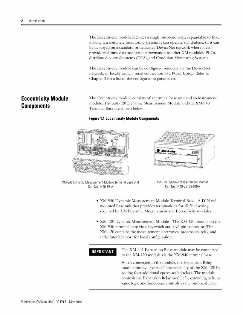
The Eccentricity module consists of a terminal base unit and an instrument module. The XM-120 Dynamic Measurement Module and the XM-940 Terminal Base are shown below.
Figure 1.1 Eccentricity Module Components
• XM-940 Dynamic Measurement Module Terminal Base - A DIN rail mounted base unit that provides terminations for all field wiring required by XM Dynamic Measurement and Eccentricity modules.
• XM-120 Dynamic Measurement Module - The XM-120 mounts on the XM-940 terminal base via a keyswitch and a 96-pin connector. The XM-120 contains the measurement electronics, processors, relay, and serial interface port for local configuration.
XM-940 Dynamic Measurement Module Terminal Base UnitCat. No. 1440-TB-A
XM-120 Dynamic Measurement ModuleCat. No. 1440-VST02-01RA
IMPORTANT The XM-441 Expansion Relay module may be connected to the XM-120 module via the XM-940 terminal base.
When connected to the module, the Expansion Relay module simply “expands” the capability of the XM-120 by adding four additional epoxy-sealed relays. The module controls the Expansion Relay module by extending to it the same logic and functional controls as the on-board relay.
Publication GMSI10-UM010C-EN-P - May 2010
Introduction 3
Using this Manual This manual introduces you to the XM-120 Eccentricity module. It is intended for anyone who installs, configures, or uses the XM-120 Eccentricity module.
Organization
To help you navigate through this manual, it is organized in chapters based on these tasks and topics.
Chapter 1 "Introduction" contains an overview of this manual and the XM-120 Eccentricity module.
Chapter 2 "Installing the XM-120 Eccentricity Module" describes how to install, wire, and use the Eccentricity module. It also provides instructions on how to install the Eccentricity firmware.
Chapter 3 "Configuration Parameters" provides a complete listing and description of the Eccentricity parameters. The parameters can be viewed and edited using the XM Serial Configuration Utility software and a personal computer.
Appendix A "Specifications" lists the technical specifications for the Eccentricity module.
Appendix B "DeviceNet Information" provides information to help you configure the module over a DeviceNet network.
Appendix C "DeviceNet Objects" provides information on the DeviceNet objects supported by the XM-120 Eccentricity module.
Appendix D "Wiring Connections for Previous Module Revisions" provides terminal block assignments and wiring diagrams of earlier revisions of the XM-120 module (before revision D01).
For definitions of terms used in this Guide, see the Glossary at the end of the Guide.
Document Conventions
There are several document conventions used in this manual, including the following:
Publication GMSI10-UM010C-EN-P - May 2010

4 Introduction
The XM-120 Eccentricity module is referred to as XM-120, Eccentricity module, device, or module throughout this manual.
TIP A tip indicates additional information which may be helpful.
EXAMPLE This convention presents an example.
Publication GMSI10-UM010C-EN-P - May 2010
Chapter 2
Installing the XM-120 Eccentricity Module
This chapter discusses how to install and wire the XM-120 Eccentricity module. It also describes the module indicators and the basic operations of the modules.
For information about See page
XM Installation Requirements 6
Mounting the Terminal Base Unit 13
Connecting Wiring for Your Module 17
Mounting the Module 35
Module Indicators 37
Basic Operations 39
Installing the XM-120 Eccentricity Firmware 40
ATTENTION Environment and EnclosureThis equipment is intended for use in a Pollution Degree 2 Industrial environment, in overvoltage Category II applications (as defined in IED publication 60664–1), at altitudes up to 2000 meters without derating.
This equipment is supplied as “open type” equipment. It must be mounted within an enclosure that is suitably designed for those specific environmental conditions that will be present, and appropriately designed to prevent personal injury resulting from accessibility to live parts. The interior of the enclosure must be accessible only by the use of a tool. Subsequent sections of this publication may contain additional information regarding specific enclosure type ratings that are required to comply with certain product safety certifications.
See NEMA Standards publication 250 and IEC publication 60529, as applicable, for explanations of the degrees of protection provided by different types of enclosures.
5 Publication GMSI10-UM010C-EN-P - May 2010
6 Installing the XM-120 Eccentricity Module
XM Installation Requirements
This section describes wire, power, and grounding requirements for an XM system.
Wiring Requirements
Use solid or stranded wire. All wiring should meet the following specifications:
• 14 to 22 AWG copper conductors without pretreatment; 8 AWG required for grounding the DIN rail for electromagnetic interference (emi) purposes
• Recommended strip length 8 millimeters (0.31 inches)
• Minimum insulation rating of 300 V
• Soldering the conductor is forbidden
• Wire ferrules can be used with stranded conductors; copper ferrules recommended
Power Requirements
Before installing your module, calculate the power requirements of all modules interconnected via their side connectors. The total current draw through the side connector cannot exceed 3A. Refer to the specifications for the specific modules for power requirements.
Figure 2.1 is an illustration of wiring modules using separate power connections.
ATTENTION See the XM Documentation and Configuration Utility CD for Hazardous Locations installation drawings. The XM Documentation and Configuration Utility CD is packaged with the XM modules.
ATTENTION A separate power connection is necessary if the total current draw of the interconnecting modules is greater than 3 A.
Publication GMSI10-UM010C-EN-P - May 2010
Installing the XM-120 Eccentricity Module 7
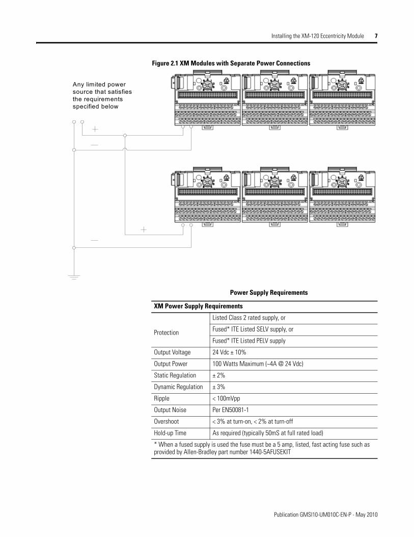
Figure 2.1 XM Modules with Separate Power Connections
Any limited power source that satisfies the requirements specified below
Power Supply Requirements
XM Power Supply Requirements
Protection
Listed Class 2 rated supply, or
Fused* ITE Listed SELV supply, or
Fused* ITE Listed PELV supply
Output Voltage 24 Vdc ± 10%
Output Power 100 Watts Maximum (~4A @ 24 Vdc)
Static Regulation ± 2%
Dynamic Regulation ± 3%
Ripple < 100mVpp
Output Noise Per EN50081-1
Overshoot < 3% at turn-on, < 2% at turn-off
Hold-up Time As required (typically 50mS at full rated load)
* When a fused supply is used the fuse must be a 5 amp, listed, fast acting fuse such as provided by Allen-Bradley part number 1440-5AFUSEKIT
Publication GMSI10-UM010C-EN-P - May 2010
8 Installing the XM-120 Eccentricity Module
Grounding Requirements
Use these grounding requirements to ensure safe electrical operating circumstances, and to help avoid potential emi and ground noise that can cause unfavorable operating conditions for your XM system.
DIN Rail Grounding
The XM modules make a chassis ground connection through the DIN rail. The DIN rail must be connected to a ground bus or grounding electrode conductor using 8 AWG or 1 inch copper braid. See Figure 2.2.
Use zinc-plated, yellow-chromated steel DIN rail (Allen-Bradley part no. 199-DR1 or 199-DR4) or equivalent to assure proper grounding. Using other DIN rail materials (e.g. aluminum, plastic, etc.), which can corrode, oxidize, or are poor conductors can result in improper or intermittent platform grounding.
IMPORTANT See Application Technique "XM Power Supply Solutions", publication ICM-AP005A-EN-E, for guidance in architecting power supplies for XM systems.
Publication GMSI10-UM010C-EN-P - May 2010
Installing the XM-120 Eccentricity Module 9
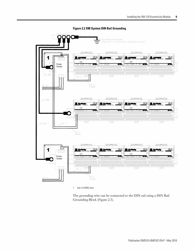
Figure 2.2 XM System DIN Rail Grounding
1 Use 14 AWG wire.
The grounding wire can be connected to the DIN rail using a DIN Rail Grounding Block (Figure 2.3).
PowerSupply
DYNAMIC MEASUREMENT1440-VST02-01RA
DYNAMIC MEASUREMENT1440-VST02-01RA
POSITION1440-TSP02-01RB
MASTER RELAY1440-RMA00-04RC
EXPANSION RELAY1440-REX00-04RD
EXPANSION RELAY1440-REX00-04RD
EXPANSION RELAY1440-REX00-04RD
EXPANSION RELAY1440-REX00-04RD
PowerSupply
DYNAMIC MEASUREMENT1440-VST02-01RA
DYNAMIC MEASUREMENT1440-VST02-01RA
EXPANSION RELAY1440-REX00-04RD
EXPANSION RELAY1440-REX00-04RD
1
1
Publication GMSI10-UM010C-EN-P - May 2010
10 Installing the XM-120 Eccentricity Module
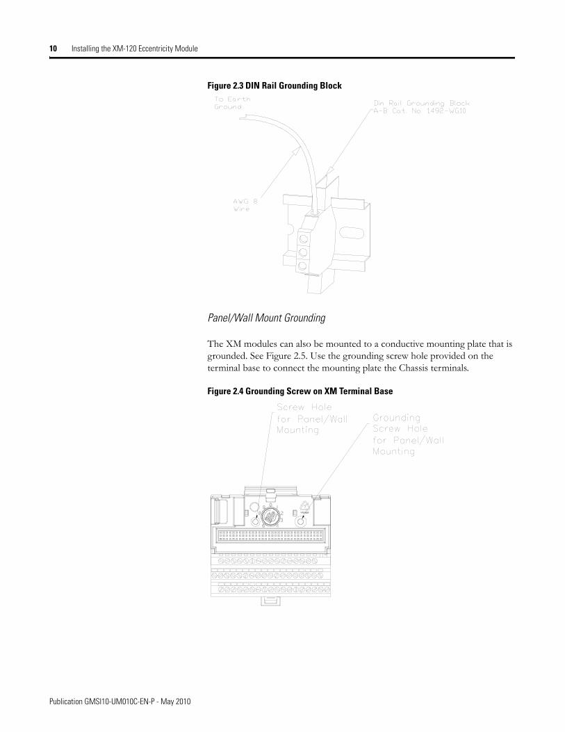
Figure 2.3 DIN Rail Grounding Block
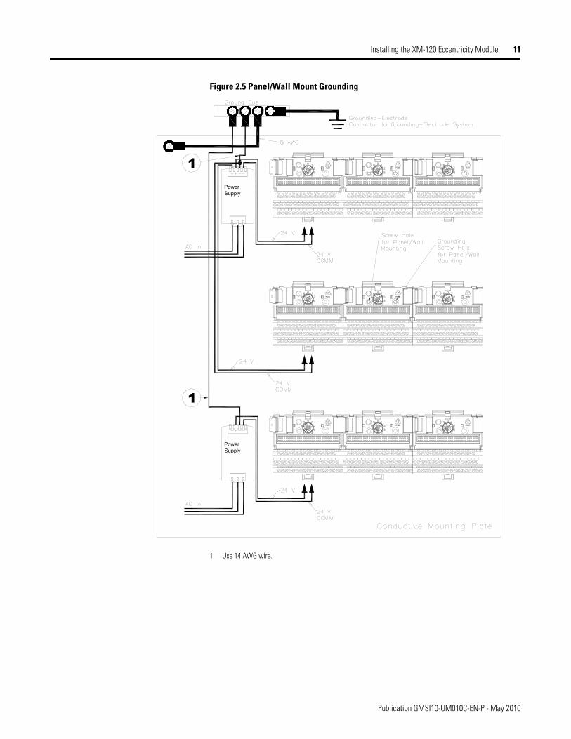
Panel/Wall Mount Grounding
The XM modules can also be mounted to a conductive mounting plate that is grounded. See Figure 2.5. Use the grounding screw hole provided on the terminal base to connect the mounting plate the Chassis terminals.
Figure 2.4 Grounding Screw on XM Terminal Base
Publication GMSI10-UM010C-EN-P - May 2010
Installing the XM-120 Eccentricity Module 11
Figure 2.5 Panel/Wall Mount Grounding
1 Use 14 AWG wire.
PowerSupply
PowerSupply
1
1
Publication GMSI10-UM010C-EN-P - May 2010
12 Installing the XM-120 Eccentricity Module
24V Common Grounding
24 V power to the XM modules must be grounded. When two or more power supplies power the XM system, ground the 24 V Commons at a single point, such as the ground bus bar.
Transducer Grounding
Make certain the transducers are electrically isolated from earth ground. Cable shields must be grounded at one end of the cable, and the other end left floating or not connected. It is recommended that where possible, the cable shield be grounded at the XM terminal base (Chassis terminal) and not at the transducer.
DeviceNet Grounding
The DeviceNet network is functionally isolated and must be referenced to earth ground at a single point. XM modules do not require an external DeviceNet power supply. Connect DeviceNet V- to earth ground at one of the XM modules, as shown in Figure 2.6.
IMPORTANT If it is not possible or practical to ground the -24Vdc supply, then it is possible for the system to be installed and operate ungrounded. However, if installed ungrounded then the system must not be connected to a ground through any other circuit unless that circuit is isolated externally. Connecting a floating system to a non-isolated ground could result in damage to the XM module(s) and/or any connected device. Also, operating the system without a ground may result in the system not performing to the published specifications regards measurement accuracy and communications speed, distance or reliability.
IMPORTANT The 24 V Common and Signal Common terminals are internally connected. They are isolated from the Chassis terminals unless they are connected to ground as described in this section. See Terminal Block Assignments on page 18 for more information.
Publication GMSI10-UM010C-EN-P - May 2010

Installing the XM-120 Eccentricity Module 13
Figure 2.6 Grounded DeviceNet V- at XM Module
For more information on the DeviceNet installation, refer to the ODVA Planning and Installation Manual - DeviceNet Cable System, which is available on the ODVA web site (http://www.odva.org).
Switch Input Grounding
The Switch Input circuits are functionally isolated from other circuits. It is recommended that the Switch RTN signal be grounded at a single point. Connect the Switch RTN signal to the XM terminal base (Chassis terminal) or directly to the DIN rail, or ground the signal at the switch or other equipment that is wired to the switch.
Mounting the Terminal Base Unit
The XM family includes several different terminal base units to serve all of the XM modules. The XM-940 terminal base, Cat. No. 1440-TB-A, is the only terminal base unit used with the Eccentricity module.
To GroundBus
ATTENTION Use of a separate DeviceNet power supply is not permitted. See Application Technique "XM Power Supply Solutions", publication ICM-AP005A-EN-E, for guidance in using XM with other DeviceNet products.
Publication GMSI10-UM010C-EN-P - May 2010
14 Installing the XM-120 Eccentricity Module
The terminal base can be DIN rail or wall/panel mounted. Refer to the specific method of mounting below.
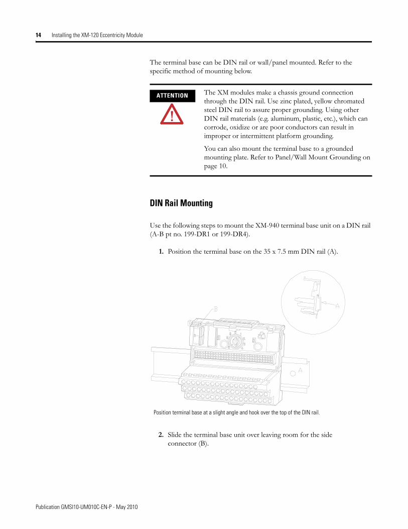
DIN Rail Mounting
Use the following steps to mount the XM-940 terminal base unit on a DIN rail (A-B pt no. 199-DR1 or 199-DR4).
1. Position the terminal base on the 35 x 7.5 mm DIN rail (A).
2. Slide the terminal base unit over leaving room for the side connector (B).
ATTENTION The XM modules make a chassis ground connection through the DIN rail. Use zinc plated, yellow chromated steel DIN rail to assure proper grounding. Using other DIN rail materials (e.g. aluminum, plastic, etc.), which can corrode, oxidize or are poor conductors can result in improper or intermittent platform grounding.
You can also mount the terminal base to a grounded mounting plate. Refer to Panel/Wall Mount Grounding on page 10.
Position terminal base at a slight angle and hook over the top of the DIN rail.
Publication GMSI10-UM010C-EN-P - May 2010
Installing the XM-120 Eccentricity Module 15
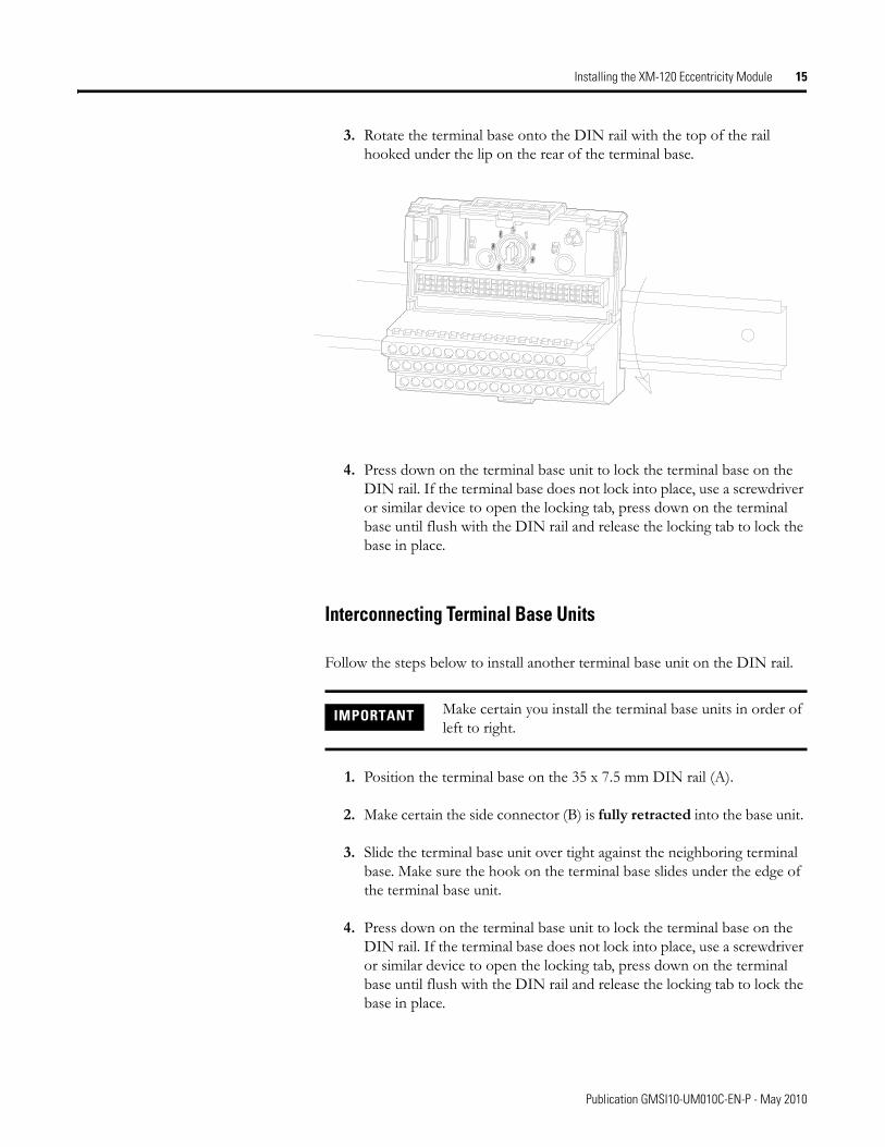
3. Rotate the terminal base onto the DIN rail with the top of the rail hooked under the lip on the rear of the terminal base.
4. Press down on the terminal base unit to lock the terminal base on the DIN rail. If the terminal base does not lock into place, use a screwdriver or similar device to open the locking tab, press down on the terminal base until flush with the DIN rail and release the locking tab to lock the base in place.
Interconnecting Terminal Base Units
Follow the steps below to install another terminal base unit on the DIN rail.
1. Position the terminal base on the 35 x 7.5 mm DIN rail (A).
2. Make certain the side connector (B) is fully retracted into the base unit.
3. Slide the terminal base unit over tight against the neighboring terminal base. Make sure the hook on the terminal base slides under the edge of the terminal base unit.
4. Press down on the terminal base unit to lock the terminal base on the DIN rail. If the terminal base does not lock into place, use a screwdriver or similar device to open the locking tab, press down on the terminal base until flush with the DIN rail and release the locking tab to lock the base in place.
IMPORTANT Make certain you install the terminal base units in order of left to right.
Publication GMSI10-UM010C-EN-P - May 2010
16 Installing the XM-120 Eccentricity Module
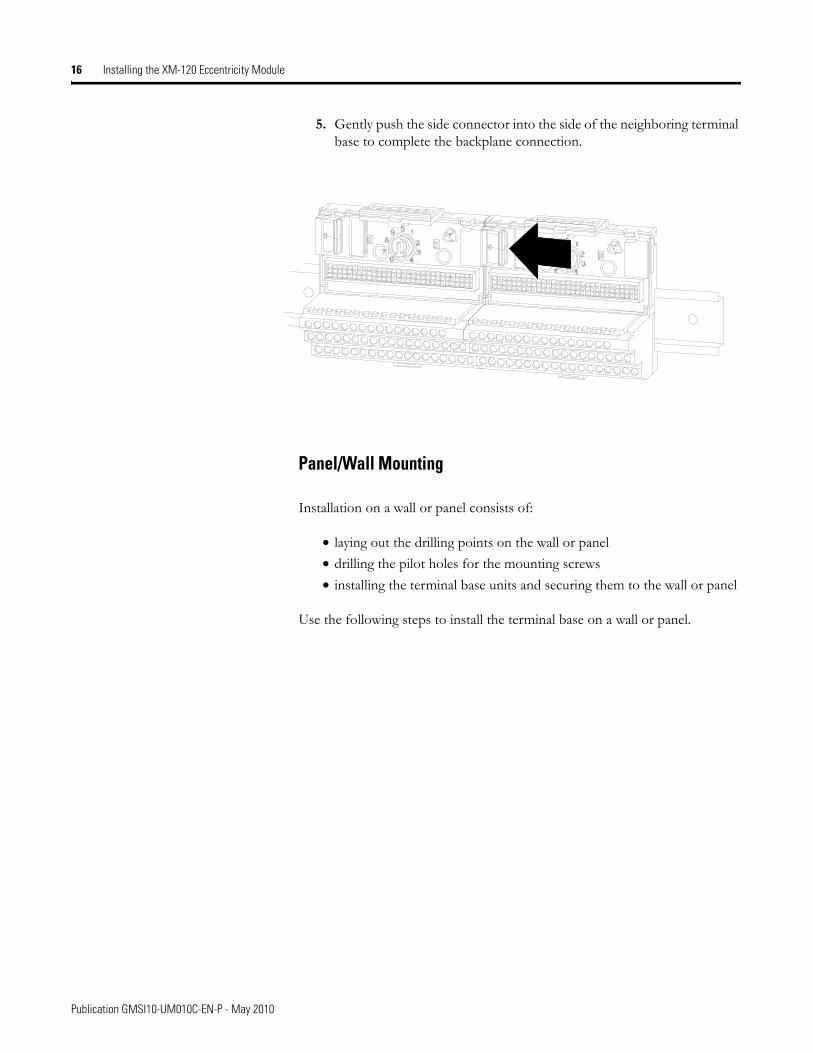
5. Gently push the side connector into the side of the neighboring terminal base to complete the backplane connection.
Panel/Wall Mounting
Installation on a wall or panel consists of:
• laying out the drilling points on the wall or panel• drilling the pilot holes for the mounting screws• installing the terminal base units and securing them to the wall or panel
Use the following steps to install the terminal base on a wall or panel.
Publication GMSI10-UM010C-EN-P - May 2010
Installing the XM-120 Eccentricity Module 17
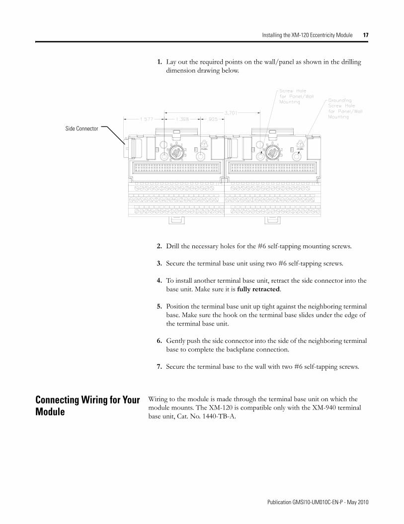
1. Lay out the required points on the wall/panel as shown in the drilling dimension drawing below.
2. Drill the necessary holes for the #6 self-tapping mounting screws.
3. Secure the terminal base unit using two #6 self-tapping screws.
4. To install another terminal base unit, retract the side connector into the base unit. Make sure it is fully retracted.
5. Position the terminal base unit up tight against the neighboring terminal base. Make sure the hook on the terminal base slides under the edge of the terminal base unit.
6. Gently push the side connector into the side of the neighboring terminal base to complete the backplane connection.
7. Secure the terminal base to the wall with two #6 self-tapping screws.
Connecting Wiring for Your Module
Wiring to the module is made through the terminal base unit on which the module mounts. The XM-120 is compatible only with the XM-940 terminal base unit, Cat. No. 1440-TB-A.
Side Connector
Publication GMSI10-UM010C-EN-P - May 2010
18 Installing the XM-120 Eccentricity Module
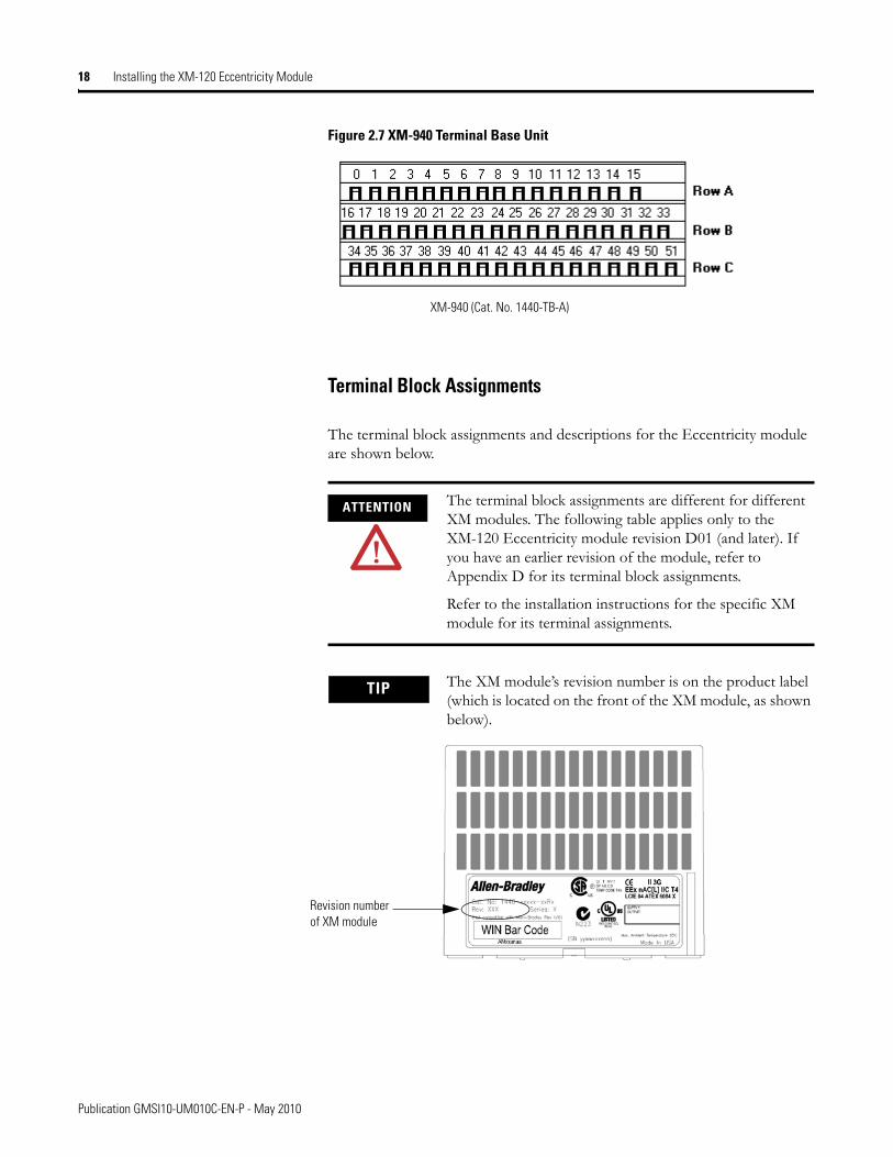
Figure 2.7 XM-940 Terminal Base Unit
Terminal Block Assignments
The terminal block assignments and descriptions for the Eccentricity module are shown below.
ATTENTION The terminal block assignments are different for different XM modules. The following table applies only to the XM-120 Eccentricity module revision D01 (and later). If you have an earlier revision of the module, refer to Appendix D for its terminal block assignments.
Refer to the installation instructions for the specific XM module for its terminal assignments.
TIP The XM module’s revision number is on the product label (which is located on the front of the XM module, as shown below).
XM-940 (Cat. No. 1440-TB-A)
Revision number of XM module
Publication GMSI10-UM010C-EN-P - May 2010
Installing the XM-120 Eccentricity Module 19
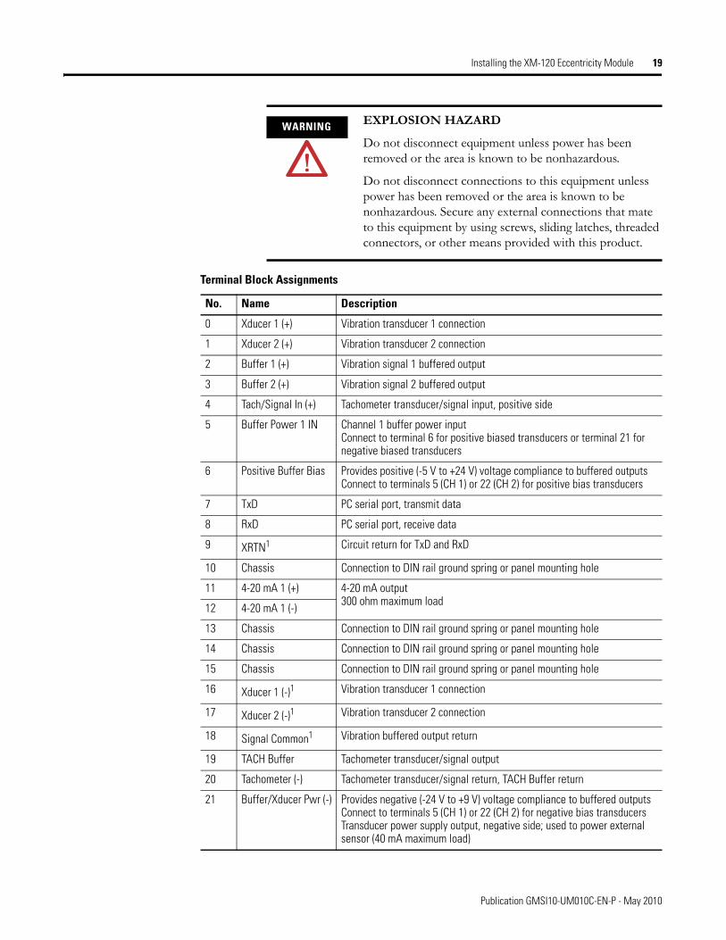
WARNING EXPLOSION HAZARD
Do not disconnect equipment unless power has been removed or the area is known to be nonhazardous.
Do not disconnect connections to this equipment unless power has been removed or the area is known to be nonhazardous. Secure any external connections that mate to this equipment by using screws, sliding latches, threaded connectors, or other means provided with this product.
Terminal Block Assignments
No. Name Description
0 Xducer 1 (+) Vibration transducer 1 connection
1 Xducer 2 (+) Vibration transducer 2 connection
2 Buffer 1 (+) Vibration signal 1 buffered output
3 Buffer 2 (+) Vibration signal 2 buffered output
4 Tach/Signal In (+) Tachometer transducer/signal input, positive side
5 Buffer Power 1 IN Channel 1 buffer power inputConnect to terminal 6 for positive biased transducers or terminal 21 for negative biased transducers
6 Positive Buffer Bias Provides positive (-5 V to +24 V) voltage compliance to buffered outputs Connect to terminals 5 (CH 1) or 22 (CH 2) for positive bias transducers
7 TxD PC serial port, transmit data
8 RxD PC serial port, receive data
9 XRTN1 Circuit return for TxD and RxD
10 Chassis Connection to DIN rail ground spring or panel mounting hole
11 4-20 mA 1 (+) 4-20 mA output 300 ohm maximum load
12 4-20 mA 1 (-)
13 Chassis Connection to DIN rail ground spring or panel mounting hole
14 Chassis Connection to DIN rail ground spring or panel mounting hole
15 Chassis Connection to DIN rail ground spring or panel mounting hole
16 Xducer 1 (-)1 Vibration transducer 1 connection
17 Xducer 2 (-)1 Vibration transducer 2 connection
18 Signal Common1 Vibration buffered output return
19 TACH Buffer Tachometer transducer/signal output
20 Tachometer (-) Tachometer transducer/signal return, TACH Buffer return
21 Buffer/Xducer Pwr (-) Provides negative (-24 V to +9 V) voltage compliance to buffered outputsConnect to terminals 5 (CH 1) or 22 (CH 2) for negative bias transducersTransducer power supply output, negative side; used to power external sensor (40 mA maximum load)
Publication GMSI10-UM010C-EN-P - May 2010
20 Installing the XM-120 Eccentricity Module
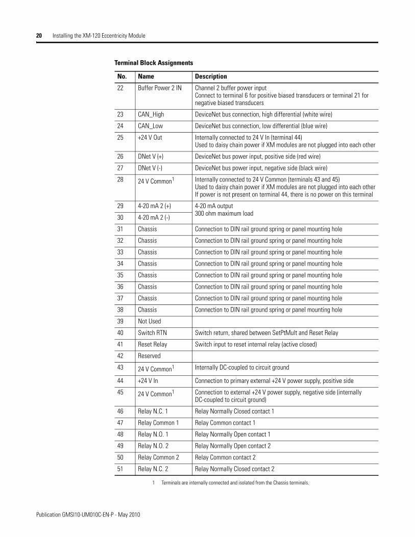
1 Terminals are internally connected and isolated from the Chassis terminals.
22 Buffer Power 2 IN Channel 2 buffer power inputConnect to terminal 6 for positive biased transducers or terminal 21 for negative biased transducers
23 CAN_High DeviceNet bus connection, high differential (white wire)
24 CAN_Low DeviceNet bus connection, low differential (blue wire)
25 +24 V Out Internally connected to 24 V In (terminal 44)Used to daisy chain power if XM modules are not plugged into each other
26 DNet V (+) DeviceNet bus power input, positive side (red wire)
27 DNet V (-) DeviceNet bus power input, negative side (black wire)
28 24 V Common1 Internally connected to 24 V Common (terminals 43 and 45)Used to daisy chain power if XM modules are not plugged into each otherIf power is not present on terminal 44, there is no power on this terminal
29 4-20 mA 2 (+) 4-20 mA output300 ohm maximum load
30 4-20 mA 2 (-)
31 Chassis Connection to DIN rail ground spring or panel mounting hole
32 Chassis Connection to DIN rail ground spring or panel mounting hole
33 Chassis Connection to DIN rail ground spring or panel mounting hole
34 Chassis Connection to DIN rail ground spring or panel mounting hole
35 Chassis Connection to DIN rail ground spring or panel mounting hole
36 Chassis Connection to DIN rail ground spring or panel mounting hole
37 Chassis Connection to DIN rail ground spring or panel mounting hole
38 Chassis Connection to DIN rail ground spring or panel mounting hole
39 Not Used
40 Switch RTN Switch return, shared between SetPtMult and Reset Relay
41 Reset Relay Switch input to reset internal relay (active closed)
42 Reserved
43 24 V Common1 Internally DC-coupled to circuit ground
44 +24 V In Connection to primary external +24 V power supply, positive side
45 24 V Common1 Connection to external +24 V power supply, negative side (internally DC-coupled to circuit ground)
46 Relay N.C. 1 Relay Normally Closed contact 1
47 Relay Common 1 Relay Common contact 1
48 Relay N.O. 1 Relay Normally Open contact 1
49 Relay N.O. 2 Relay Normally Open contact 2
50 Relay Common 2 Relay Common contact 2
51 Relay N.C. 2 Relay Normally Closed contact 2
Terminal Block Assignments
No. Name Description
Publication GMSI10-UM010C-EN-P - May 2010
Installing the XM-120 Eccentricity Module 21
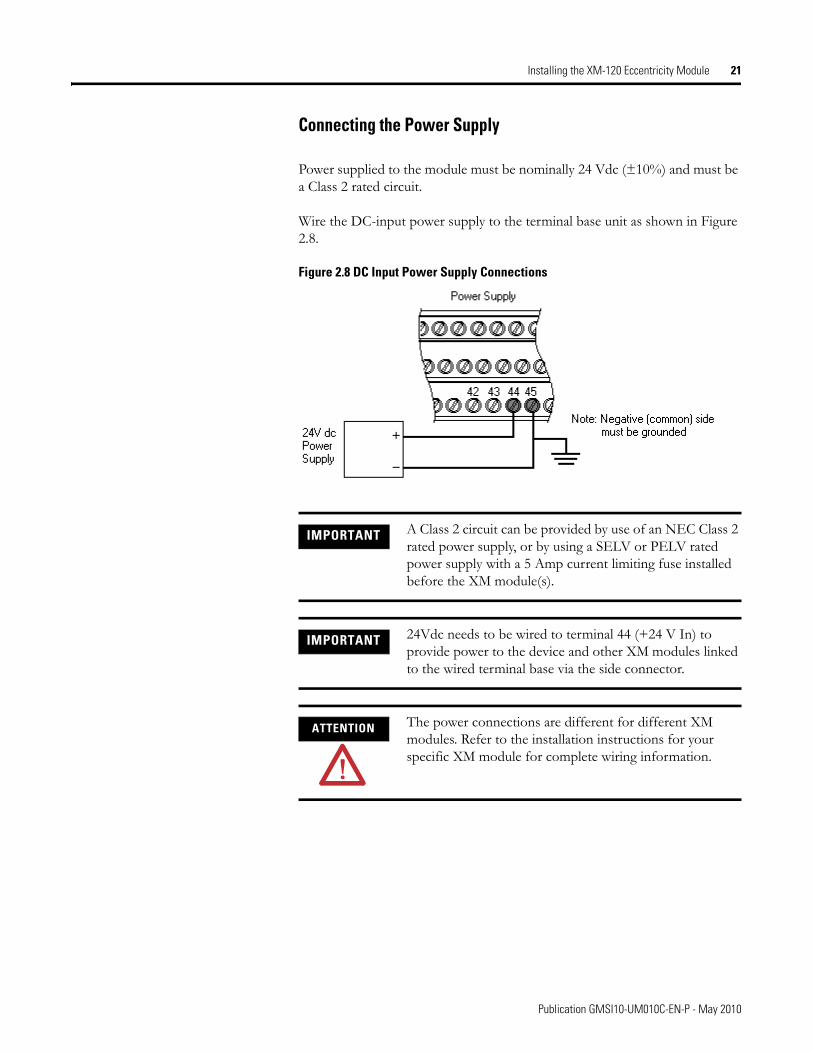
Connecting the Power Supply
Power supplied to the module must be nominally 24 Vdc (±10%) and must be a Class 2 rated circuit.
Wire the DC-input power supply to the terminal base unit as shown in Figure 2.8.
Figure 2.8 DC Input Power Supply Connections
IMPORTANT A Class 2 circuit can be provided by use of an NEC Class 2 rated power supply, or by using a SELV or PELV rated power supply with a 5 Amp current limiting fuse installed before the XM module(s).
IMPORTANT 24Vdc needs to be wired to terminal 44 (+24 V In) to provide power to the device and other XM modules linked to the wired terminal base via the side connector.
ATTENTION The power connections are different for different XM modules. Refer to the installation instructions for your specific XM module for complete wiring information.
Publication GMSI10-UM010C-EN-P - May 2010
22 Installing the XM-120 Eccentricity Module
Connecting the Relays
The XM-120 has both Normally Open (NO) and Normally Closed (NC) relay contacts. Normally Open relay contacts close when the control output is energized. Normally Closed relay contacts open when the control output is energized.
The alarms associated with the relay and whether the relay is normally de-energized (non-failsafe) or normally energized (failsafe) depends on the configuration of the module. Refer to Relay Parameters on page 52 for details.
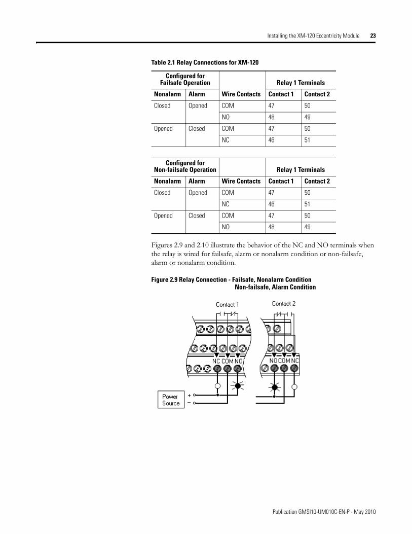
Table 2.1 shows the on-board relay connections for the module.
IMPORTANT All XM relays are double pole. This means that each relay has two contacts in which each contact operates independently but identically. The following information and illustrations show wiring solutions for both contacts; although, in many applications it may be necessary to wire only one contact.
TIP The Expansion Relay module may be connected to the module to provide additional relays. Refer the XM-441 Expansion Relay Module User Guide for wiring details.
IMPORTANT The NC/NO terminal descriptions (page 20) correspond to a de-energized (unpowered) relay.
When the relay is configured for non-failsafe operation, the relay is normally de-energized.
When the relay is configured for failsafe operation, the relay is normally energized, and the behavior of the NC and NO terminals is inverted.
Publication GMSI10-UM010C-EN-P - May 2010
Installing the XM-120 Eccentricity Module 23
Figures 2.9 and 2.10 illustrate the behavior of the NC and NO terminals when the relay is wired for failsafe, alarm or nonalarm condition or non-failsafe, alarm or nonalarm condition.
Figure 2.9 Relay Connection - Failsafe, Nonalarm ConditionNon-failsafe, Alarm Condition
Table 2.1 Relay Connections for XM-120
Configured for Failsafe Operation Relay 1 Terminals
Nonalarm Alarm Wire Contacts Contact 1 Contact 2
Closed Opened COM 47 50
NO 48 49
Opened Closed COM 47 50
NC 46 51
Configured for Non-failsafe Operation Relay 1 Terminals
Nonalarm Alarm Wire Contacts Contact 1 Contact 2
Closed Opened COM 47 50
NC 46 51
Opened Closed COM 47 50
NO 48 49
Publication GMSI10-UM010C-EN-P - May 2010
24 Installing the XM-120 Eccentricity Module
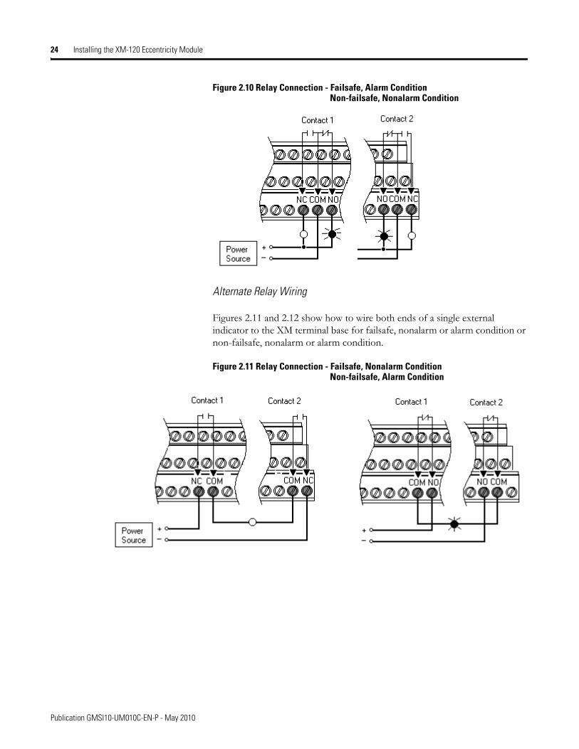
Figure 2.10 Relay Connection - Failsafe, Alarm ConditionNon-failsafe, Nonalarm Condition
Alternate Relay Wiring
Figures 2.11 and 2.12 show how to wire both ends of a single external indicator to the XM terminal base for failsafe, nonalarm or alarm condition or non-failsafe, nonalarm or alarm condition.
Figure 2.11 Relay Connection - Failsafe, Nonalarm ConditionNon-failsafe, Alarm Condition
Publication GMSI10-UM010C-EN-P - May 2010
Installing the XM-120 Eccentricity Module 25
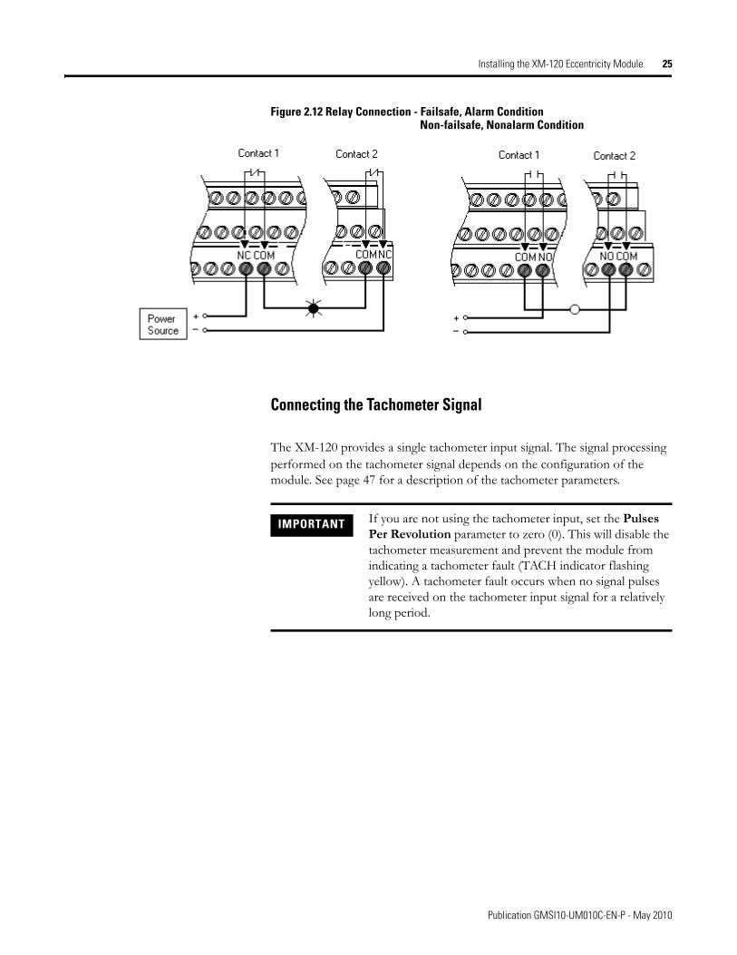
Figure 2.12 Relay Connection - Failsafe, Alarm ConditionNon-failsafe, Nonalarm Condition
Connecting the Tachometer Signal
The XM-120 provides a single tachometer input signal. The signal processing performed on the tachometer signal depends on the configuration of the module. See page 47 for a description of the tachometer parameters.
IMPORTANT If you are not using the tachometer input, set the Pulses Per Revolution parameter to zero (0). This will disable the tachometer measurement and prevent the module from indicating a tachometer fault (TACH indicator flashing yellow). A tachometer fault occurs when no signal pulses are received on the tachometer input signal for a relatively long period.
Publication GMSI10-UM010C-EN-P - May 2010
26 Installing the XM-120 Eccentricity Module
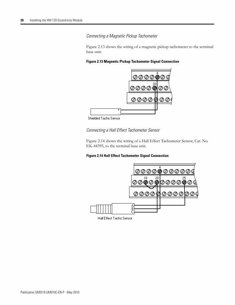
Connecting a Magnetic Pickup Tachometer
Figure 2.13 shows the wiring of a magnetic pickup tachometer to the terminal base unit.
Figure 2.13 Magnetic Pickup Tachometer Signal Connection
Connecting a Hall Effect Tachometer Sensor
Figure 2.14 shows the wiring of a Hall Effect Tachometer Sensor, Cat. No. EK-44395, to the terminal base unit.
Figure 2.14 Hall Effect Tachometer Signal Connection
Publication GMSI10-UM010C-EN-P - May 2010
Installing the XM-120 Eccentricity Module 27
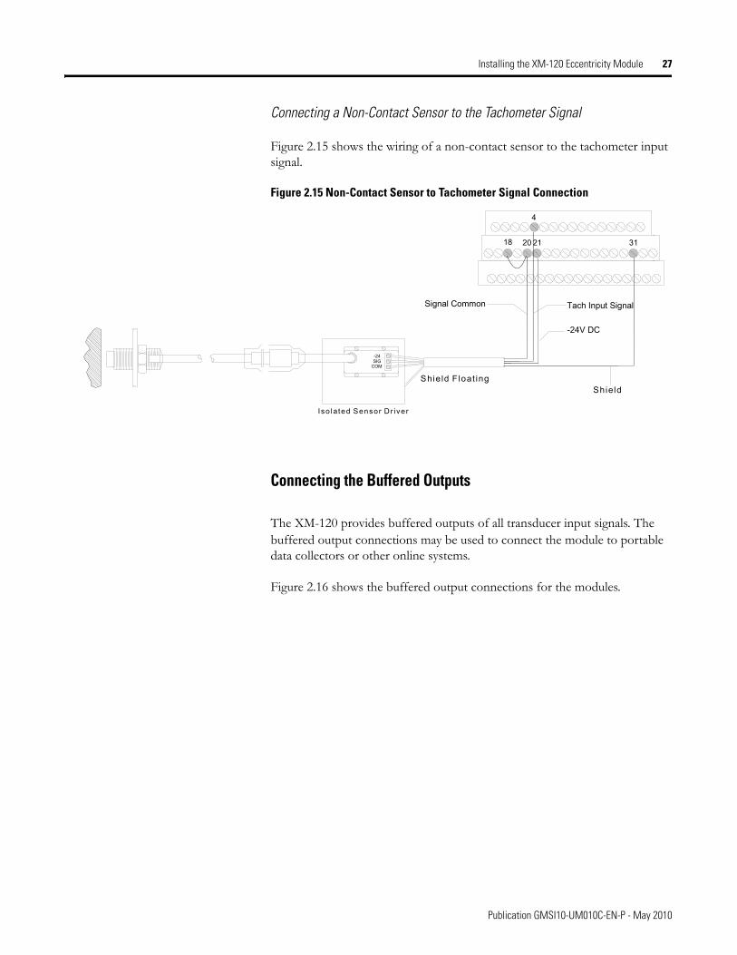
Connecting a Non-Contact Sensor to the Tachometer Signal
Figure 2.15 shows the wiring of a non-contact sensor to the tachometer input signal.
Figure 2.15 Non-Contact Sensor to Tachometer Signal Connection
Connecting the Buffered Outputs
The XM-120 provides buffered outputs of all transducer input signals. The buffered output connections may be used to connect the module to portable data collectors or other online systems.
Figure 2.16 shows the buffered output connections for the modules.
SIG-24
COM
Signal Common Tach Input Signal
-24V DC
Shield S hie ld F loat ing
Iso lated Sensor Dr iver
20 21 31
4
18
Publication GMSI10-UM010C-EN-P - May 2010
28 Installing the XM-120 Eccentricity Module
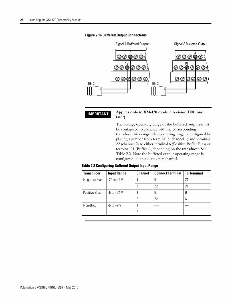
Figure 2.16 Buffered Output Connections
IMPORTANT Applies only to XM-120 module revision D01 (and later).
The voltage operating range of the buffered outputs must be configured to coincide with the corresponding transducer bias range. This operating range is configured by placing a jumper from terminal 5 (channel 1) and terminal 22 (channel 2) to either terminal 6 (Positive Buffer Bias) or terminal 21 (Buffer -), depending on the transducer. See Table 2.2. Note the buffered output operating range is configured independently per channel.
Table 2.2 Configuring Buffered Output Input Range
Transducer Input Range Channel Connect Terminal To Terminal
Negative Bias -24 to +9 V 1 5 21
2 22 21
Positive Bias -5 to +24 V 1 5 6
2 22 6
Non-Bias -5 to +9 V 1 ---- ----
2 ---- ----
Publication GMSI10-UM010C-EN-P - May 2010
Installing the XM-120 Eccentricity Module 29
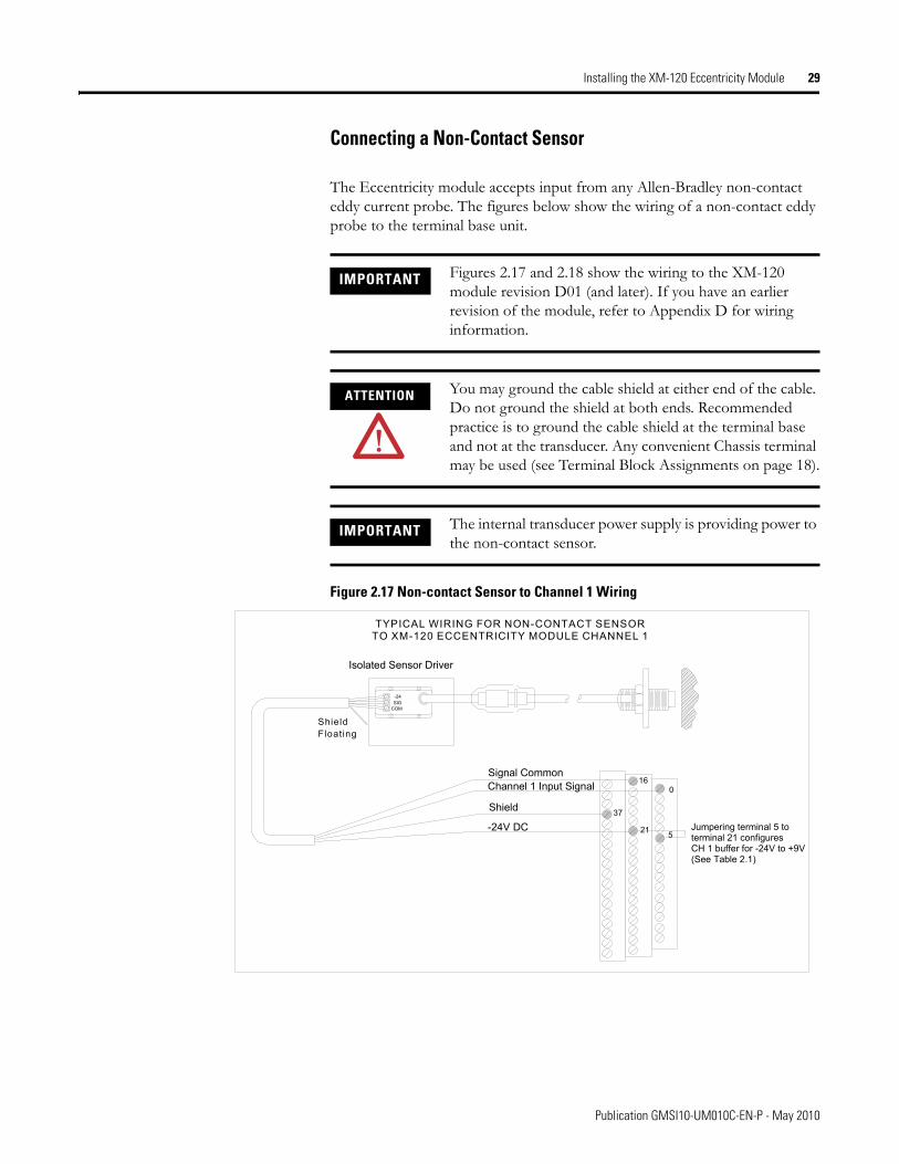
Connecting a Non-Contact Sensor
The Eccentricity module accepts input from any Allen-Bradley non-contact eddy current probe. The figures below show the wiring of a non-contact eddy probe to the terminal base unit.
Figure 2.17 Non-contact Sensor to Channel 1 Wiring
IMPORTANT Figures 2.17 and 2.18 show the wiring to the XM-120 module revision D01 (and later). If you have an earlier revision of the module, refer to Appendix D for wiring information.
ATTENTION You may ground the cable shield at either end of the cable. Do not ground the shield at both ends. Recommended practice is to ground the cable shield at the terminal base and not at the transducer. Any convenient Chassis terminal may be used (see Terminal Block Assignments on page 18).
IMPORTANT The internal transducer power supply is providing power to the non-contact sensor.
TYPICAL WIRING FOR NON-CONTACT SENSORTO XM-120 ECCENTRICITY MODULE CHANNEL 1
COMSIG-24
Channel 1 Input Signal
-24V DC
016
Signal Common
21 5Jumpering terminal 5 toterminal 21 configures CH 1 buffer for -24V to +9V(See Table 2.1)
Isolated Sensor Driver
Shield
ShieldFloating
37
Publication GMSI10-UM010C-EN-P - May 2010
30 Installing the XM-120 Eccentricity Module
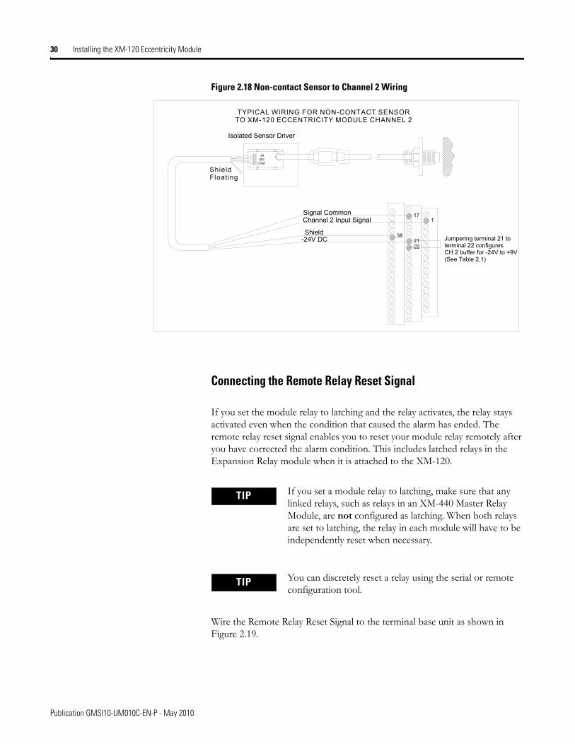
Figure 2.18 Non-contact Sensor to Channel 2 Wiring
Connecting the Remote Relay Reset Signal
If you set the module relay to latching and the relay activates, the relay stays activated even when the condition that caused the alarm has ended. The remote relay reset signal enables you to reset your module relay remotely after you have corrected the alarm condition. This includes latched relays in the Expansion Relay module when it is attached to the XM-120.
Wire the Remote Relay Reset Signal to the terminal base unit as shown in Figure 2.19.
TYPICAL WIRING FOR NON-CONTACT SENSORTO XM-120 ECCENTRICITY MODULE CHANNEL 2
COMSIG-24
Channel 2 Input Signal
-24V DC
117
22
Signal Common
21 Jumper ing terminal 21 toterminal 22 configures CH 2 buffer for -24V to +9V(See Table 2.1)
Isolated Sensor Driver
Shield
ShieldFloating
38
TIP If you set a module relay to latching, make sure that any linked relays, such as relays in an XM-440 Master Relay Module, are not configured as latching. When both relays are set to latching, the relay in each module will have to be independently reset when necessary.
TIP You can discretely reset a relay using the serial or remote configuration tool.
Publication GMSI10-UM010C-EN-P - May 2010
Installing the XM-120 Eccentricity Module 31
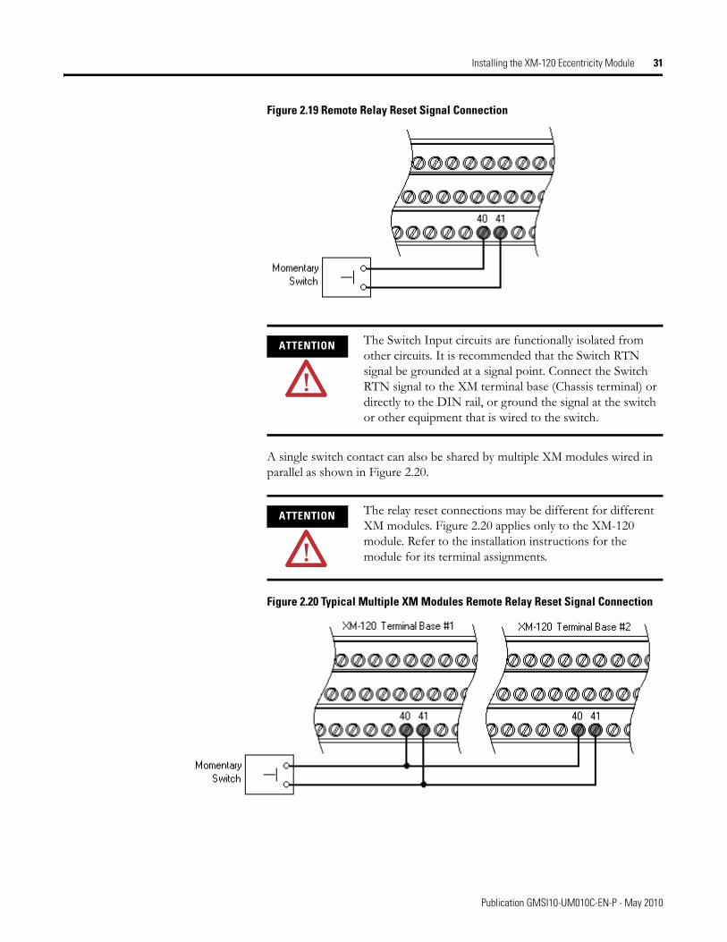
Figure 2.19 Remote Relay Reset Signal Connection
A single switch contact can also be shared by multiple XM modules wired in parallel as shown in Figure 2.20.
Figure 2.20 Typical Multiple XM Modules Remote Relay Reset Signal Connection
ATTENTION The Switch Input circuits are functionally isolated from other circuits. It is recommended that the Switch RTN signal be grounded at a signal point. Connect the Switch RTN signal to the XM terminal base (Chassis terminal) or directly to the DIN rail, or ground the signal at the switch or other equipment that is wired to the switch.
ATTENTION The relay reset connections may be different for different XM modules. Figure 2.20 applies only to the XM-120 module. Refer to the installation instructions for the module for its terminal assignments.
Publication GMSI10-UM010C-EN-P - May 2010
32 Installing the XM-120 Eccentricity Module
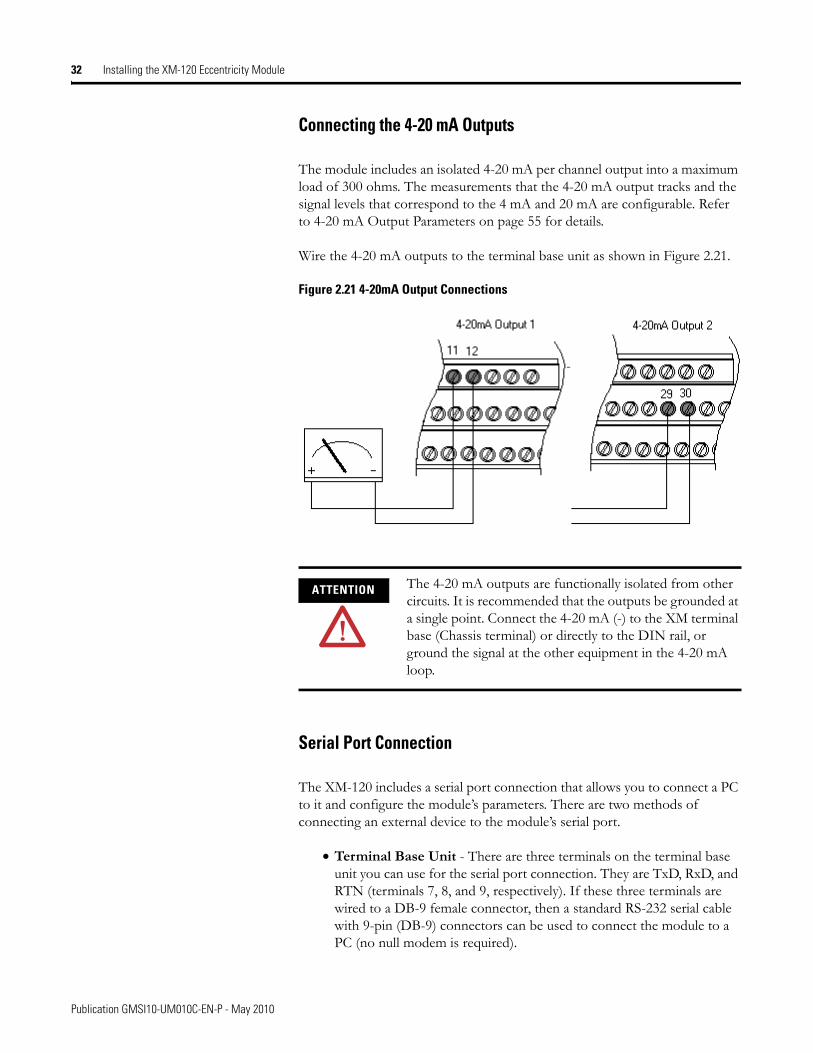
Connecting the 4-20 mA Outputs
The module includes an isolated 4-20 mA per channel output into a maximum load of 300 ohms. The measurements that the 4-20 mA output tracks and the signal levels that correspond to the 4 mA and 20 mA are configurable. Refer to 4-20 mA Output Parameters on page 55 for details.
Wire the 4-20 mA outputs to the terminal base unit as shown in Figure 2.21.
Figure 2.21 4-20mA Output Connections
Serial Port Connection
The XM-120 includes a serial port connection that allows you to connect a PC to it and configure the module’s parameters. There are two methods of connecting an external device to the module’s serial port.
• Terminal Base Unit - There are three terminals on the terminal base unit you can use for the serial port connection. They are TxD, RxD, and RTN (terminals 7, 8, and 9, respectively). If these three terminals are wired to a DB-9 female connector, then a standard RS-232 serial cable with 9-pin (DB-9) connectors can be used to connect the module to a PC (no null modem is required).
ATTENTION The 4-20 mA outputs are functionally isolated from other circuits. It is recommended that the outputs be grounded at a single point. Connect the 4-20 mA (-) to the XM terminal base (Chassis terminal) or directly to the DIN rail, or ground the signal at the other equipment in the 4-20 mA loop.
-
Publication GMSI10-UM010C-EN-P - May 2010
Installing the XM-120 Eccentricity Module 33
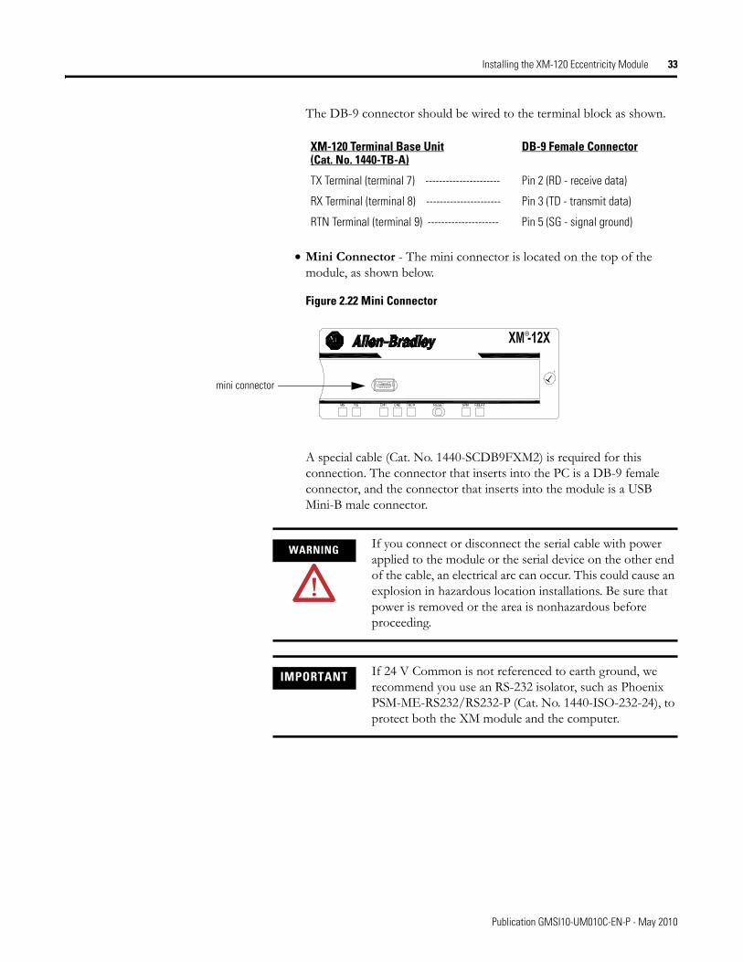
The DB-9 connector should be wired to the terminal block as shown.
• Mini Connector - The mini connector is located on the top of the module, as shown below.
Figure 2.22 Mini Connector
A special cable (Cat. No. 1440-SCDB9FXM2) is required for this connection. The connector that inserts into the PC is a DB-9 female connector, and the connector that inserts into the module is a USB Mini-B male connector.
XM-120 Terminal Base Unit(Cat. No. 1440-TB-A)
DB-9 Female Connector
TX Terminal (terminal 7) ---------------------- Pin 2 (RD - receive data)
RX Terminal (terminal 8) ---------------------- Pin 3 (TD - transmit data)
RTN Terminal (terminal 9) --------------------- Pin 5 (SG - signal ground)
mini connector
WARNING If you connect or disconnect the serial cable with power applied to the module or the serial device on the other end of the cable, an electrical arc can occur. This could cause an explosion in hazardous location installations. Be sure that power is removed or the area is nonhazardous before proceeding.
IMPORTANT If 24 V Common is not referenced to earth ground, we recommend you use an RS-232 isolator, such as Phoenix PSM-ME-RS232/RS232-P (Cat. No. 1440-ISO-232-24), to protect both the XM module and the computer.
Publication GMSI10-UM010C-EN-P - May 2010
34 Installing the XM-120 Eccentricity Module
DeviceNet Connection
The XM-120 includes a DeviceNet™ connection that allows the module to communicate with a programmable controller, DCS, or another XM module.
DeviceNet is an open, global, industry-standard communications network designed to provide an interface through a single cable from a programmable controller to a smart device such as the XM-120. As multiple XM modules are interconnected, DeviceNet also serves as the communication bus and protocol that efficiently transfers data between the XM modules.
Connect the DeviceNet cable to the terminal base unit as shown.
Connect To Terminal
Red Wire DNet V+ 26 (optional—see note)
White Wire CAN High 23
Bare Wire Shield (Chassis) 10
Blue Wire CAN Low 24
Black Wire DNet V- 27
IMPORTANT The DeviceNet power circuit through the XM module interconnect, which is rated at only 300 mA, is not intended or designed to power DeviceNet loads. Doing so could damage the module or terminal base.
To preclude this possibility, even unintentionally, it is recommended that DeviceNet V+ be left unconnected.
ATTENTION You must ground the DeviceNet shield at only one location. Connecting the DeviceNet shield to terminal 10 will ground the DeviceNet shield at the XM module. If you intend to terminate the shield elsewhere, do not connect the shield to terminal 10.
ATTENTION The DeviceNet network must also be referenced to earth at only one location. Connect DNet V- to earth or chassis at one of the XM modules.
Publication GMSI10-UM010C-EN-P - May 2010
Installing the XM-120 Eccentricity Module 35
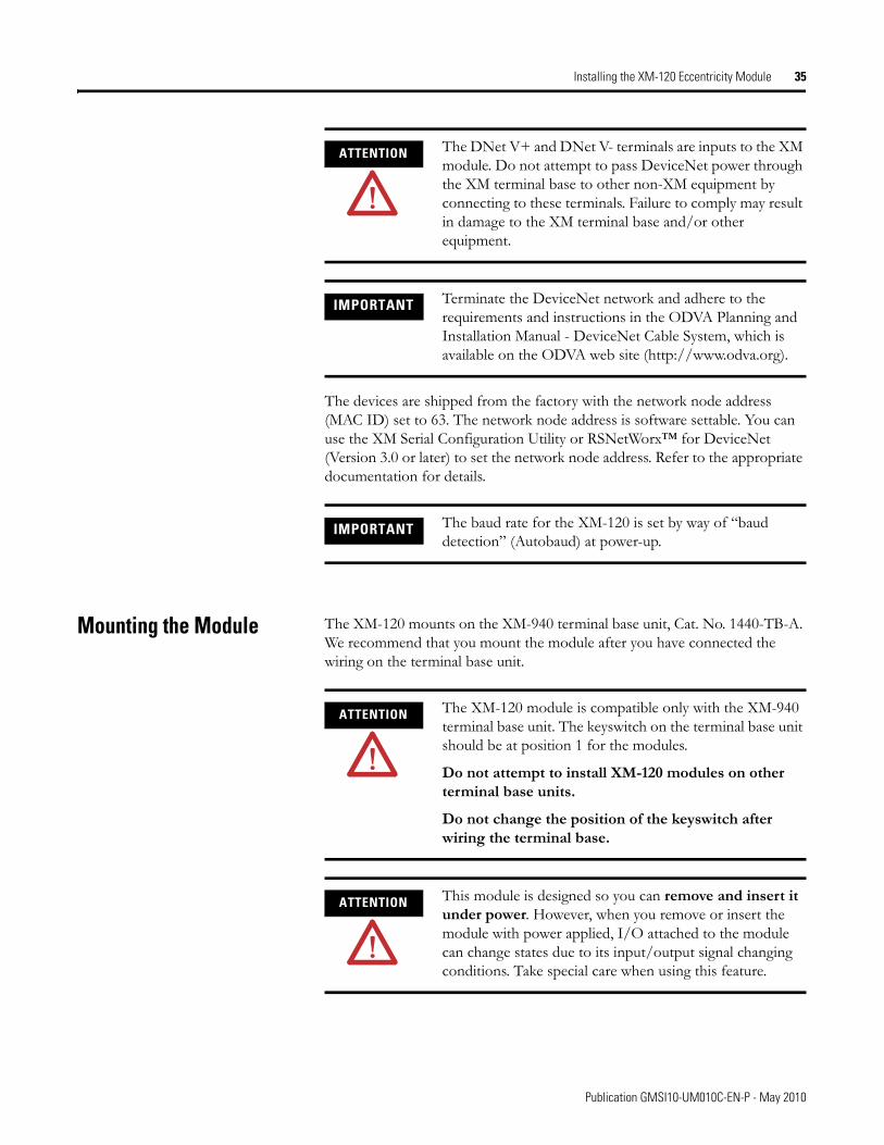
The devices are shipped from the factory with the network node address (MAC ID) set to 63. The network node address is software settable. You can use the XM Serial Configuration Utility or RSNetWorx™ for DeviceNet (Version 3.0 or later) to set the network node address. Refer to the appropriate documentation for details.
Mounting the Module The XM-120 mounts on the XM-940 terminal base unit, Cat. No. 1440-TB-A. We recommend that you mount the module after you have connected the wiring on the terminal base unit.
ATTENTION The DNet V+ and DNet V- terminals are inputs to the XM module. Do not attempt to pass DeviceNet power through the XM terminal base to other non-XM equipment by connecting to these terminals. Failure to comply may result in damage to the XM terminal base and/or other equipment.
IMPORTANT Terminate the DeviceNet network and adhere to the requirements and instructions in the ODVA Planning and Installation Manual - DeviceNet Cable System, which is available on the ODVA web site (http://www.odva.org).
IMPORTANT The baud rate for the XM-120 is set by way of “baud detection” (Autobaud) at power-up.
ATTENTION The XM-120 module is compatible only with the XM-940 terminal base unit. The keyswitch on the terminal base unit should be at position 1 for the modules.
Do not attempt to install XM-120 modules on other terminal base units.
Do not change the position of the keyswitch after wiring the terminal base.
ATTENTION This module is designed so you can remove and insert it under power. However, when you remove or insert the module with power applied, I/O attached to the module can change states due to its input/output signal changing conditions. Take special care when using this feature.
Publication GMSI10-UM010C-EN-P - May 2010
36 Installing the XM-120 Eccentricity Module
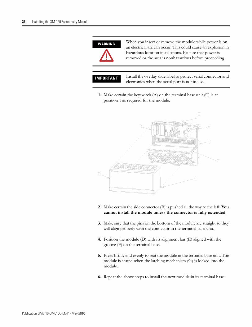
1. Make certain the keyswitch (A) on the terminal base unit (C) is at position 1 as required for the module.
2. Make certain the side connector (B) is pushed all the way to the left. You cannot install the module unless the connector is fully extended.
3. Make sure that the pins on the bottom of the module are straight so they will align properly with the connector in the terminal base unit.
4. Position the module (D) with its alignment bar (E) aligned with the groove (F) on the terminal base.
5. Press firmly and evenly to seat the module in the terminal base unit. The module is seated when the latching mechanism (G) is locked into the module.
6. Repeat the above steps to install the next module in its terminal base.
WARNING When you insert or remove the module while power is on, an electrical arc can occur. This could cause an explosion in hazardous location installations. Be sure that power is removed or the area is nonhazardous before proceeding.
IMPORTANT Install the overlay slide label to protect serial connector and electronics when the serial port is not in use.
Publication GMSI10-UM010C-EN-P - May 2010
Installing the XM-120 Eccentricity Module 37
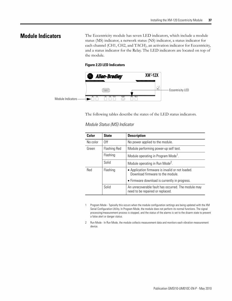
Module Indicators The Eccentricity module has seven LED indicators, which include a module status (MS) indicator, a network status (NS) indicator, a status indicator for each channel (CH1, CH2, and TACH), an activation indicator for Eccentricity, and a status indicator for the Relay. The LED indicators are located on top of the module.
Figure 2.23 LED Indicators
The following tables describe the states of the LED status indicators.
Module Status (MS) Indicator
1 Program Mode - Typically this occurs when the module configuration settings are being updated with the XM Serial Configuration Utility. In Program Mode, the module does not perform its normal functions. The signal processing/measurement process is stopped, and the status of the alarms is set to the disarm state to prevent a false alert or danger status.
2 Run Mode - In Run Mode, the module collects measurement data and monitors each vibration measurement device.
Module Indicators
Eccentricity LED
Color State Description
No color Off No power applied to the module.
Green Flashing Red Module performing power-up self test.
Flashing Module operating in Program Mode1.
Solid Module operating in Run Mode2.
Red Flashing • Application firmware is invalid or not loaded. Download firmware to the module.
• Firmware download is currently in progress.
Solid An unrecoverable fault has occurred. The module may need to be repaired or replaced.
Publication GMSI10-UM010C-EN-P - May 2010
38 Installing the XM-120 Eccentricity Module
Network Status (NS) Indicator
1 Normal condition when the module is not a slave to an XM-440, PLC, or other master device.
Channel 1, Channel 2, and Tachometer Status Indicators
Eccentricity Indicator
Color State Description
No color Off Module is not online.
• Module is autobauding.
• No power applied to the module, look at Module Status LED.
Green Flashing Module is online (DeviceNet) but no connections are currently established.1
Solid Module is online with connections currently established.
Red Flashing One or more I/O connections are in the timed-out state.
Solid Failed communications (duplicate MAC ID or Bus-off).
Color State Description
No color Off • Normal operation within alarm limits on the channel.
• No power applied to the module, look at Module Status LED.
Yellow Solid An alert level alarm condition exists on the channel (and no transducer fault, tachometer fault, or danger level alarm condition exists).
Flashing Tach LED
A tachometer fault (no transducer fault) condition exists on the tachometer channel
Flashing CH1/2 LED
A tachometer fault condition exists and the channel’s alarm speed range is enabled (and no transducer fault on the channel’s transducer).
Red Solid A danger level alarm condition exists on the channel (and no transducer fault or tachometer fault condition exists).
Flashing A transducer fault condition exists on the channel.
Color State Description
Yellow Off Either alarm is actively monitoring the eccentricity measurement.
Solid Neither alarm is actively monitoring the eccentricity measurement. This occurs when both alarms have the status of DISARM (alarms are disabled, the machine speed is outside of the alarm’s speed range, or the module is in Program mode).
Publication GMSI10-UM010C-EN-P - May 2010
Installing the XM-120 Eccentricity Module 39
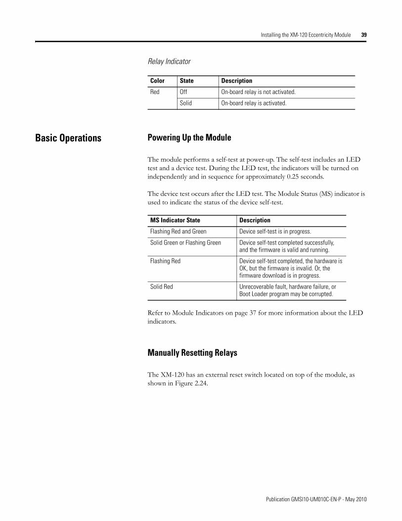
Relay Indicator
Basic Operations Powering Up the Module
The module performs a self-test at power-up. The self-test includes an LED test and a device test. During the LED test, the indicators will be turned on independently and in sequence for approximately 0.25 seconds.
The device test occurs after the LED test. The Module Status (MS) indicator is used to indicate the status of the device self-test.
Refer to Module Indicators on page 37 for more information about the LED indicators.
Manually Resetting Relays
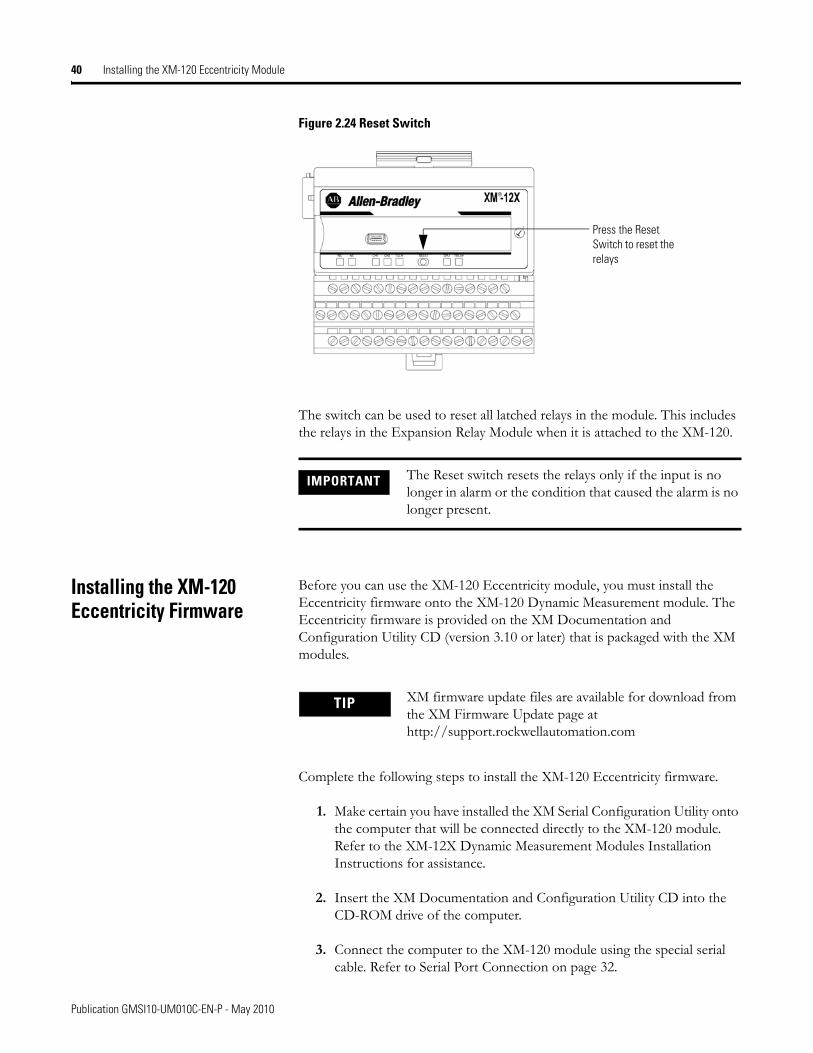
The XM-120 has an external reset switch located on top of the module, as shown in Figure 2.24.
Color State Description
Red Off On-board relay is not activated.
Solid On-board relay is activated.
MS Indicator State Description
Flashing Red and Green Device self-test is in progress.
Solid Green or Flashing Green Device self-test completed successfully, and the firmware is valid and running.
Flashing Red Device self-test completed, the hardware is OK, but the firmware is invalid. Or, the firmware download is in progress.
Solid Red Unrecoverable fault, hardware failure, or Boot Loader program may be corrupted.
Publication GMSI10-UM010C-EN-P - May 2010
40 Installing the XM-120 Eccentricity Module
Figure 2.24 Reset Switch
The switch can be used to reset all latched relays in the module. This includes the relays in the Expansion Relay Module when it is attached to the XM-120.
Installing the XM-120 Eccentricity Firmware
Before you can use the XM-120 Eccentricity module, you must install the Eccentricity firmware onto the XM-120 Dynamic Measurement module. The Eccentricity firmware is provided on the XM Documentation and Configuration Utility CD (version 3.10 or later) that is packaged with the XM modules.
Complete the following steps to install the XM-120 Eccentricity firmware.
1. Make certain you have installed the XM Serial Configuration Utility onto the computer that will be connected directly to the XM-120 module. Refer to the XM-12X Dynamic Measurement Modules Installation Instructions for assistance.
2. Insert the XM Documentation and Configuration Utility CD into the CD-ROM drive of the computer.
3. Connect the computer to the XM-120 module using the special serial cable. Refer to Serial Port Connection on page 32.
IMPORTANT The Reset switch resets the relays only if the input is no longer in alarm or the condition that caused the alarm is no longer present.
Press the Reset Switch to reset the relays
TIP XM firmware update files are available for download from the XM Firmware Update page at http://support.rockwellautomation.com
Publication GMSI10-UM010C-EN-P - May 2010
Installing the XM-120 Eccentricity Module 41
4. Power up the XM-120 module if you haven’t already done so, and start the XM Serial Configuration Utility program. Click the Start program, and then select Programs > Entek > XM > Serial Config Utility.
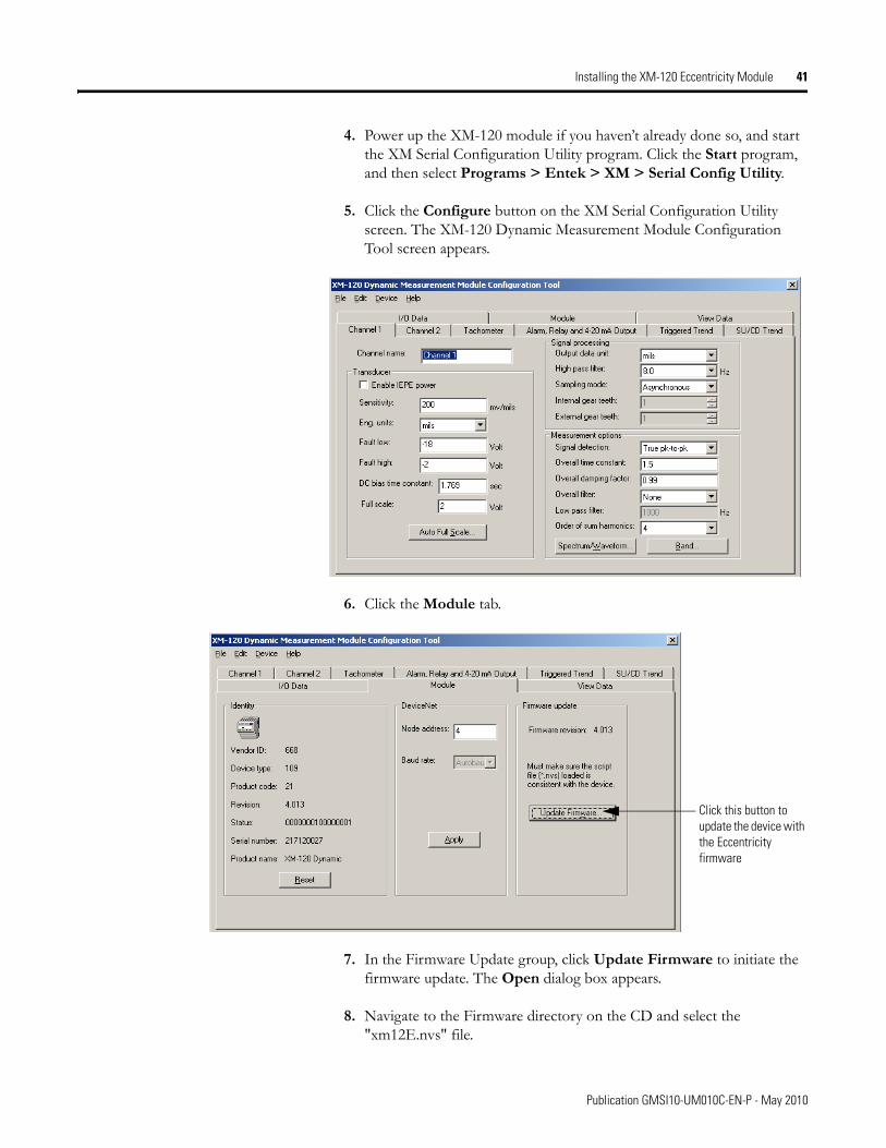
5. Click the Configure button on the XM Serial Configuration Utility screen. The XM-120 Dynamic Measurement Module Configuration Tool screen appears.
6. Click the Module tab.
7. In the Firmware Update group, click Update Firmware to initiate the firmware update. The Open dialog box appears.
8. Navigate to the Firmware directory on the CD and select the "xm12E.nvs" file.
Click this button to update the device with the Eccentricity firmware
Publication GMSI10-UM010C-EN-P - May 2010
42 Installing the XM-120 Eccentricity Module
9. Click Open to start the firmware update and click Yes to confirm. The Configuration Tool begins the update and shows its progress in the Progress dialog box.
10. When the update completes, the message "The module is configured with the factory defaults. You need to download a configuration." appears. Click OK.
11. Click OK again to return to the XM Serial Configuration Utility screen. Notice that the XM Module icon displays XM-12E instead of XM-120.
12. You are now ready to configure the Eccentricity module. Click the Configure button to display the Eccentricity parameters in the Configuration Tool. Refer to Chapter 3 for a complete list of the Eccentricity configuration parameters.
TIP Review and edit the Eccentricity parameters as necessary. When you are finished, download the parameters to the module. The module will remain in Program mode until you download a configuration.
TIP For assistance on how to use the XM Serial Configuration Utility, refer to the online help.
Publication GMSI10-UM010C-EN-P - May 2010
Chapter 3
Configuration Parameters
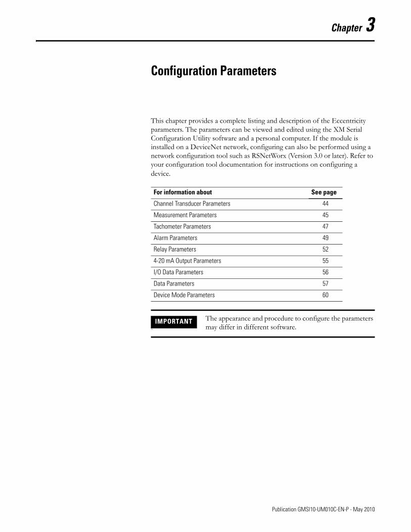
This chapter provides a complete listing and description of the Eccentricity parameters. The parameters can be viewed and edited using the XM Serial Configuration Utility software and a personal computer. If the module is installed on a DeviceNet network, configuring can also be performed using a network configuration tool such as RSNetWorx (Version 3.0 or later). Refer to your configuration tool documentation for instructions on configuring a device.
For information about See page
Channel Transducer Parameters 44
Measurement Parameters 45
Tachometer Parameters 47
Alarm Parameters 49
Relay Parameters 52
4-20 mA Output Parameters 55
I/O Data Parameters 56
Data Parameters 57
Device Mode Parameters 60
IMPORTANTThe
The appearance and procedure to configure the parameters may differ in different software.
43 Publication GMSI10-UM010C-EN-P - May 2010
44 Configuration Parameters
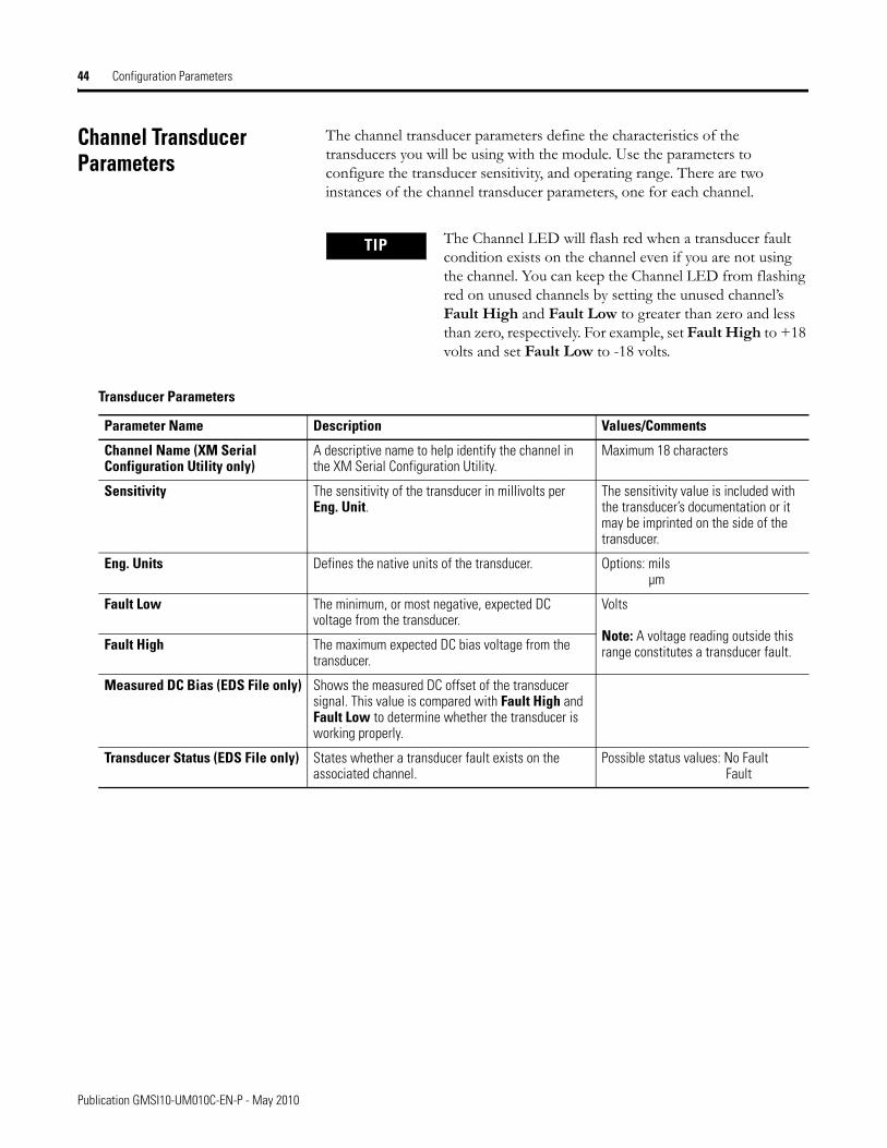
Channel Transducer Parameters
The channel transducer parameters define the characteristics of the transducers you will be using with the module. Use the parameters to configure the transducer sensitivity, and operating range. There are two instances of the channel transducer parameters, one for each channel.
TIP The Channel LED will flash red when a transducer fault condition exists on the channel even if you are not using the channel. You can keep the Channel LED from flashing red on unused channels by setting the unused channel’s Fault High and Fault Low to greater than zero and less than zero, respectively. For example, set Fault High to +18 volts and set Fault Low to -18 volts.
Transducer Parameters
Parameter Name Description Values/Comments
Channel Name (XM Serial Configuration Utility only)
A descriptive name to help identify the channel in the XM Serial Configuration Utility.
Maximum 18 characters
Sensitivity The sensitivity of the transducer in millivolts per Eng. Unit.
The sensitivity value is included with the transducer’s documentation or it may be imprinted on the side of the transducer.
Eng. Units Defines the native units of the transducer. Options: milsµm
Fault Low The minimum, or most negative, expected DC voltage from the transducer.
Volts
Note: A voltage reading outside this range constitutes a transducer fault.Fault High The maximum expected DC bias voltage from the
transducer.
Measured DC Bias (EDS File only) Shows the measured DC offset of the transducer signal. This value is compared with Fault High and Fault Low to determine whether the transducer is working properly.
Transducer Status (EDS File only) States whether a transducer fault exists on the associated channel.
Possible status values: No FaultFault
Publication GMSI10-UM010C-EN-P - May 2010
Configuration Parameters 45
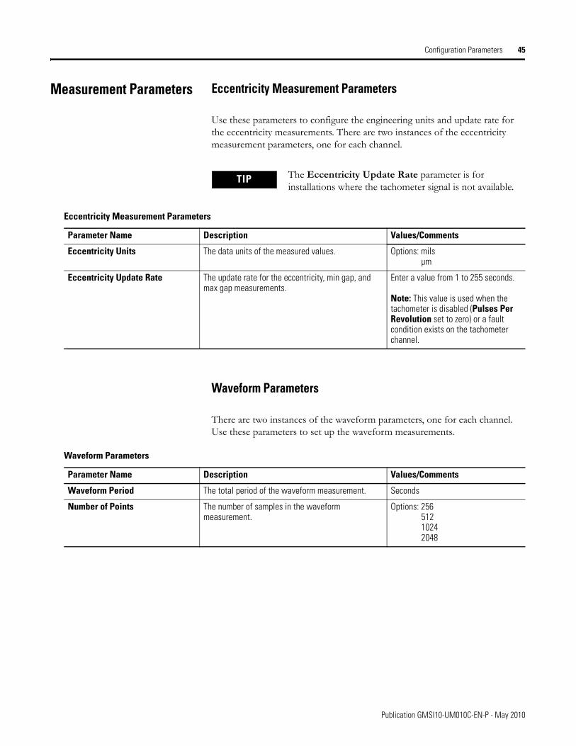
Measurement Parameters Eccentricity Measurement Parameters
Use these parameters to configure the engineering units and update rate for the eccentricity measurements. There are two instances of the eccentricity measurement parameters, one for each channel.
Waveform Parameters
There are two instances of the waveform parameters, one for each channel. Use these parameters to set up the waveform measurements.
TIP The Eccentricity Update Rate parameter is for installations where the tachometer signal is not available.
Eccentricity Measurement Parameters
Parameter Name Description Values/Comments
Eccentricity Units The data units of the measured values. Options: milsµm
Eccentricity Update Rate The update rate for the eccentricity, min gap, and max gap measurements.
Enter a value from 1 to 255 seconds.
Note: This value is used when the tachometer is disabled (Pulses Per Revolution set to zero) or a fault condition exists on the tachometer channel.
Waveform Parameters
Parameter Name Description Values/Comments
Waveform Period The total period of the waveform measurement. Seconds
Number of Points The number of samples in the waveform measurement.
Options: 25651210242048
Publication GMSI10-UM010C-EN-P - May 2010
46 Configuration Parameters
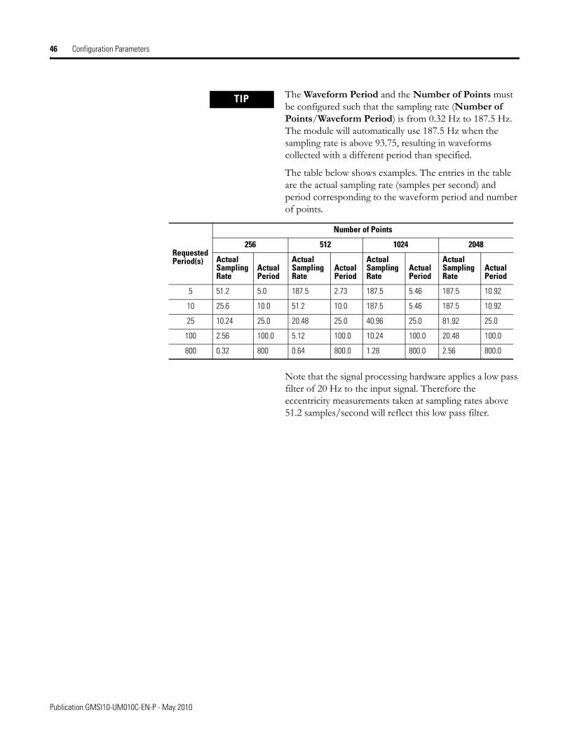
TIP The Waveform Period and the Number of Points must be configured such that the sampling rate (Number of Points/Waveform Period) is from 0.32 Hz to 187.5 Hz. The module will automatically use 187.5 Hz when the sampling rate is above 93.75, resulting in waveforms collected with a different period than specified.
The table below shows examples. The entries in the table are the actual sampling rate (samples per second) and period corresponding to the waveform period and number of points.
Note that the signal processing hardware applies a low pass filter of 20 Hz to the input signal. Therefore the eccentricity measurements taken at sampling rates above 51.2 samples/second will reflect this low pass filter.
Number of Points
Requested Period(s)
256 512 1024 2048
Actual Sampling Rate
Actual Period
Actual Sampling Rate
Actual Period
Actual Sampling Rate
Actual Period
Actual Sampling Rate
Actual Period
5 51.2 5.0 187.5 2.73 187.5 5.46 187.5 10.92
10 25.6 10.0 51.2 10.0 187.5 5.46 187.5 10.92
25 10.24 25.0 20.48 25.0 40.96 25.0 81.92 25.0
100 2.56 100.0 5.12 100.0 10.24 100.0 20.48 100.0
800 0.32 800 0.64 800.0 1.28 800.0 2.56 800.0
Publication GMSI10-UM010C-EN-P - May 2010
Configuration Parameters 47
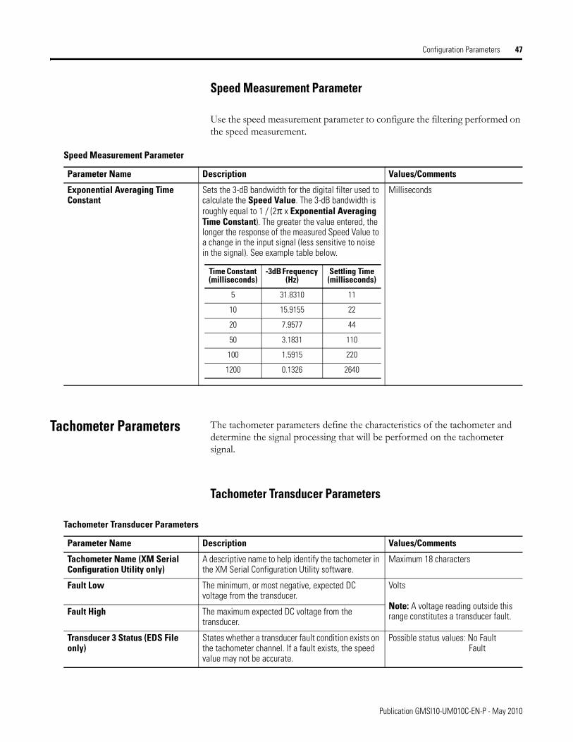
Speed Measurement Parameter
Use the speed measurement parameter to configure the filtering performed on the speed measurement.
Tachometer Parameters The tachometer parameters define the characteristics of the tachometer and determine the signal processing that will be performed on the tachometer signal.
Tachometer Transducer Parameters
Speed Measurement Parameter
Parameter Name Description Values/Comments
Exponential Averaging Time Constant
Sets the 3-dB bandwidth for the digital filter used to calculate the Speed Value. The 3-dB bandwidth is roughly equal to 1 / (2π x Exponential Averaging Time Constant). The greater the value entered, the longer the response of the measured Speed Value to a change in the input signal (less sensitive to noise in the signal). See example table below.
Milliseconds
Time Constant (milliseconds)
-3dB Frequency (Hz)
Settling Time (milliseconds)
5 31.8310 11
10 15.9155 22
20 7.9577 44
50 3.1831 110
100 1.5915 220
1200 0.1326 2640
Tachometer Transducer Parameters
Parameter Name Description Values/Comments
Tachometer Name (XM Serial Configuration Utility only)
A descriptive name to help identify the tachometer in the XM Serial Configuration Utility software.
Maximum 18 characters
Fault Low The minimum, or most negative, expected DC voltage from the transducer.
Volts
Note: A voltage reading outside this range constitutes a transducer fault.Fault High The maximum expected DC voltage from the
transducer.
Transducer 3 Status (EDS File only)
States whether a transducer fault condition exists on the tachometer channel. If a fault exists, the speed value may not be accurate.
Possible status values: No FaultFault
Publication GMSI10-UM010C-EN-P - May 2010
48 Configuration Parameters
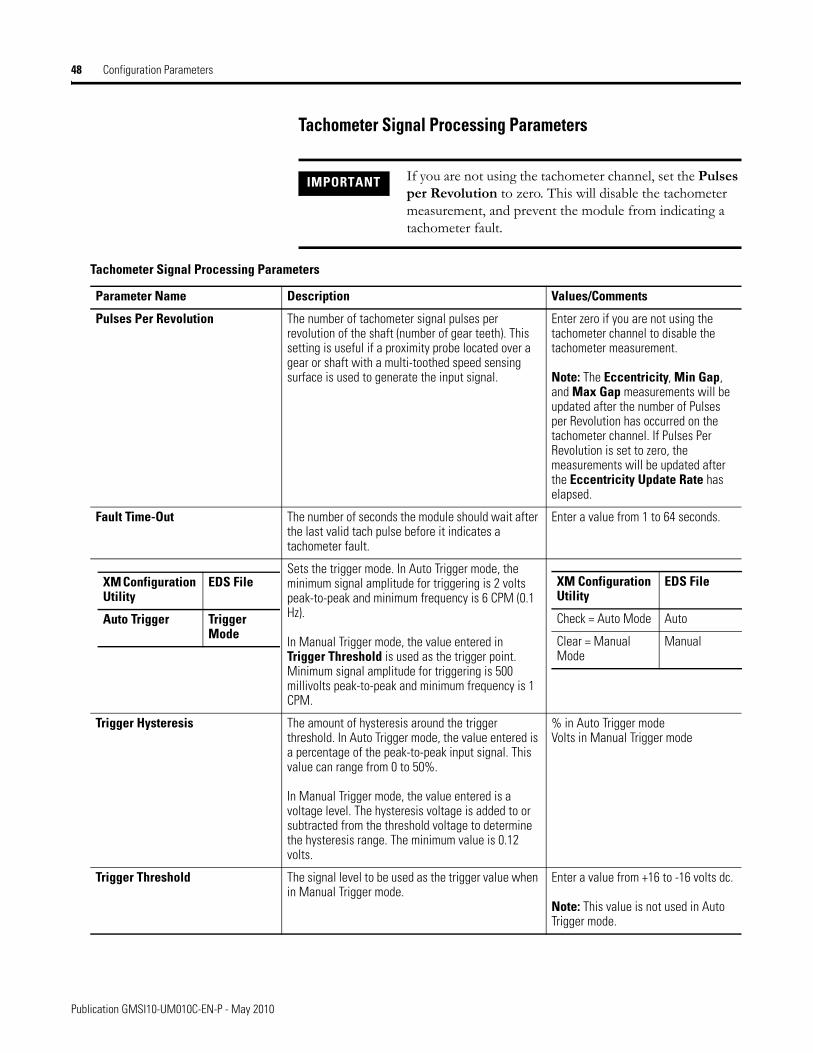
Tachometer Signal Processing Parameters
IMPORTANT If you are not using the tachometer channel, set the Pulses per Revolution to zero. This will disable the tachometer measurement, and prevent the module from indicating a tachometer fault.
Tachometer Signal Processing Parameters
Parameter Name Description Values/Comments
Pulses Per Revolution The number of tachometer signal pulses per revolution of the shaft (number of gear teeth). This setting is useful if a proximity probe located over a gear or shaft with a multi-toothed speed sensing surface is used to generate the input signal.
Enter zero if you are not using the tachometer channel to disable the tachometer measurement.
Note: The Eccentricity, Min Gap, and Max Gap measurements will be updated after the number of Pulses per Revolution has occurred on the tachometer channel. If Pulses Per Revolution is set to zero, the measurements will be updated after the Eccentricity Update Rate has elapsed.
Fault Time-Out The number of seconds the module should wait after the last valid tach pulse before it indicates a tachometer fault.
Enter a value from 1 to 64 seconds.
Sets the trigger mode. In Auto Trigger mode, the minimum signal amplitude for triggering is 2 volts peak-to-peak and minimum frequency is 6 CPM (0.1 Hz).
In Manual Trigger mode, the value entered in Trigger Threshold is used as the trigger point. Minimum signal amplitude for triggering is 500 millivolts peak-to-peak and minimum frequency is 1 CPM.
Trigger Hysteresis The amount of hysteresis around the trigger threshold. In Auto Trigger mode, the value entered is a percentage of the peak-to-peak input signal. This value can range from 0 to 50%.
In Manual Trigger mode, the value entered is a voltage level. The hysteresis voltage is added to or subtracted from the threshold voltage to determine the hysteresis range. The minimum value is 0.12 volts.
% in Auto Trigger modeVolts in Manual Trigger mode
Trigger Threshold
The signal level to be used as the trigger value when in Manual Trigger mode.
Enter a value from +16 to -16 volts dc.
Note: This value is not used in Auto Trigger mode.
XM Configuration Utility
EDS File
Auto Trigger Trigger Mode
XM Configuration Utility
EDS File
Check = Auto Mode Auto
Clear = Manual Mode
Manual
Publication GMSI10-UM010C-EN-P - May 2010
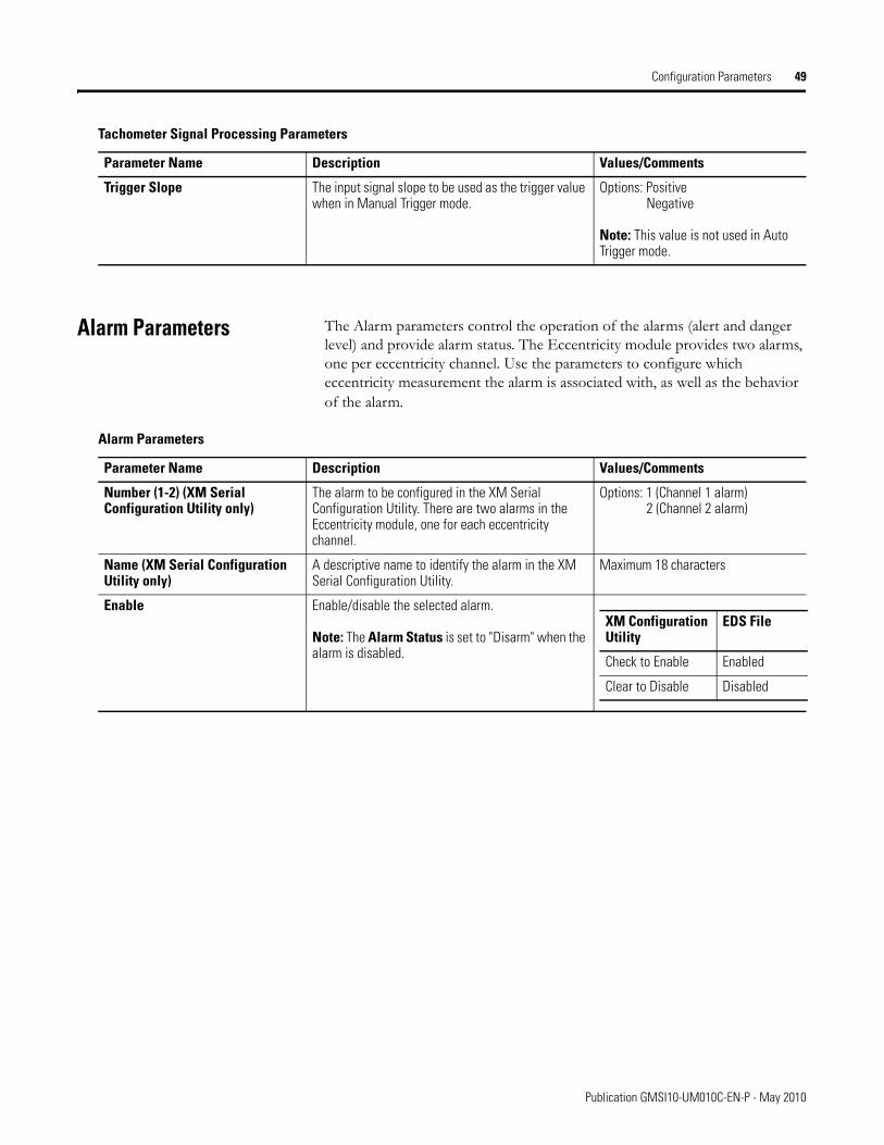
Configuration Parameters 49
Alarm Parameters The Alarm parameters control the operation of the alarms (alert and danger level) and provide alarm status. The Eccentricity module provides two alarms, one per eccentricity channel. Use the parameters to configure which eccentricity measurement the alarm is associated with, as well as the behavior of the alarm.
Trigger Slope The input signal slope to be used as the trigger value when in Manual Trigger mode.
Options: PositiveNegative
Note: This value is not used in Auto Trigger mode.
Tachometer Signal Processing Parameters
Parameter Name Description Values/Comments
Alarm Parameters
Parameter Name Description Values/Comments
Number (1-2) (XM Serial Configuration Utility only)
The alarm to be configured in the XM Serial Configuration Utility. There are two alarms in the Eccentricity module, one for each eccentricity channel.
Options: 1 (Channel 1 alarm)2 (Channel 2 alarm)
Name (XM Serial Configuration Utility only)
A descriptive name to identify the alarm in the XM Serial Configuration Utility.
Maximum 18 characters
Enable Enable/disable the selected alarm.
Note: The Alarm Status is set to "Disarm" when the alarm is disabled.
XM Configuration Utility
EDS File
Check to Enable Enabled
Clear to Disable Disabled
Publication GMSI10-UM010C-EN-P - May 2010
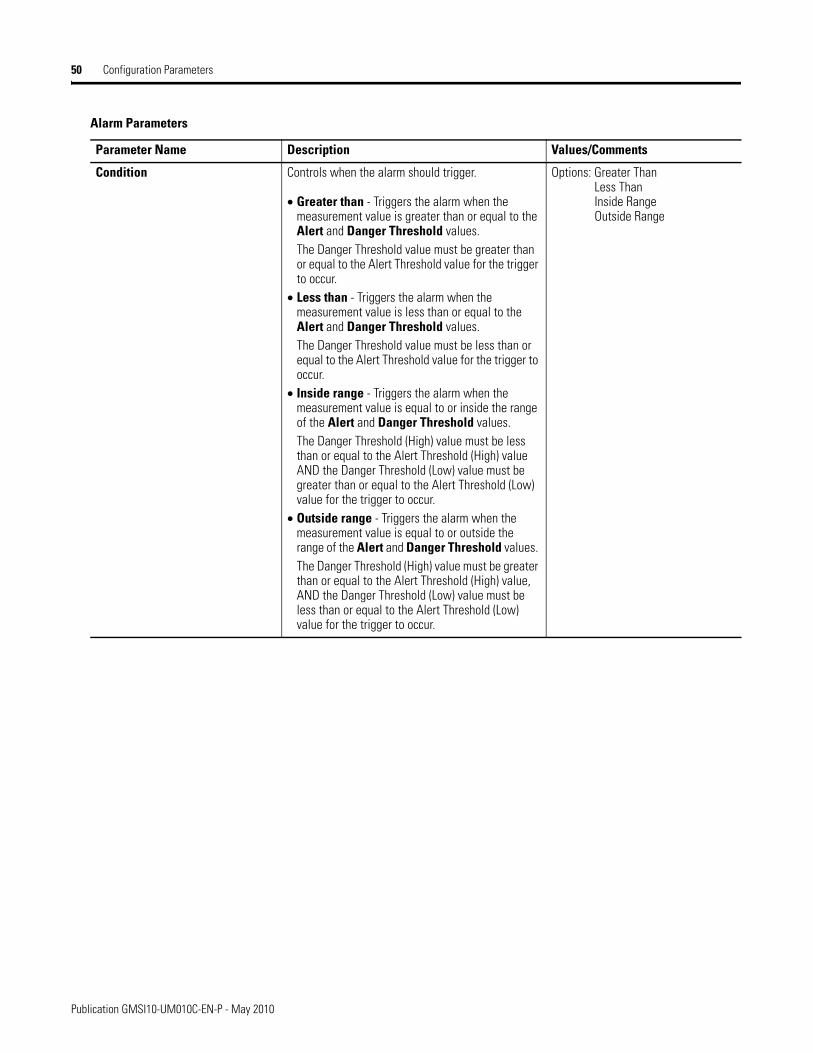
50 Configuration Parameters
Condition Controls when the alarm should trigger.
• Greater than - Triggers the alarm when the measurement value is greater than or equal to the Alert and Danger Threshold values. The Danger Threshold value must be greater than or equal to the Alert Threshold value for the trigger to occur.
• Less than - Triggers the alarm when the measurement value is less than or equal to the Alert and Danger Threshold values. The Danger Threshold value must be less than or equal to the Alert Threshold value for the trigger to occur.
• Inside range - Triggers the alarm when the measurement value is equal to or inside the range of the Alert and Danger Threshold values. The Danger Threshold (High) value must be less than or equal to the Alert Threshold (High) value AND the Danger Threshold (Low) value must be greater than or equal to the Alert Threshold (Low) value for the trigger to occur.
• Outside range - Triggers the alarm when the measurement value is equal to or outside the range of the Alert and Danger Threshold values. The Danger Threshold (High) value must be greater than or equal to the Alert Threshold (High) value, AND the Danger Threshold (Low) value must be less than or equal to the Alert Threshold (Low) value for the trigger to occur.
Options: Greater ThanLess ThanInside RangeOutside Range
Alarm Parameters
Parameter Name Description Values/Comments
Publication GMSI10-UM010C-EN-P - May 2010
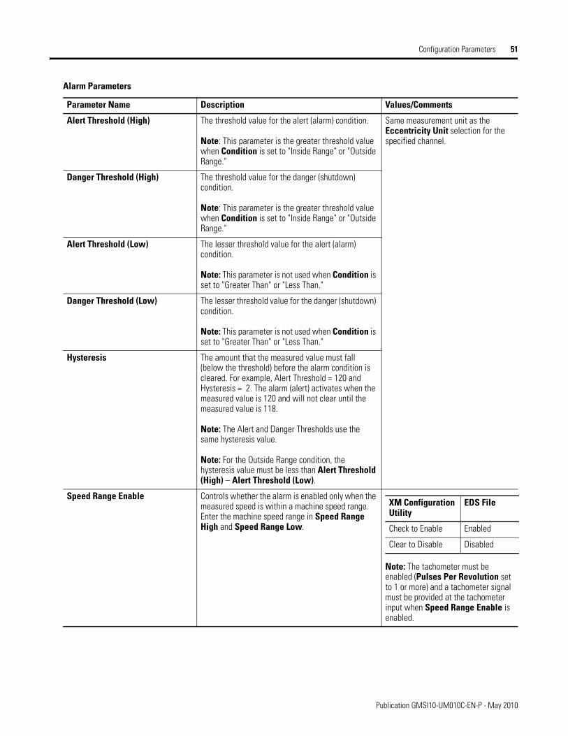
Configuration Parameters 51
Alert Threshold (High)
The threshold value for the alert (alarm) condition.
Note: This parameter is the greater threshold value when Condition is set to "Inside Range" or "Outside Range."
Same measurement unit as the Eccentricity Unit selection for the specified channel.
Danger Threshold (High) The threshold value for the danger (shutdown) condition.
Note: This parameter is the greater threshold value when Condition is set to "Inside Range" or "Outside Range."
Alert Threshold (Low) The lesser threshold value for the alert (alarm) condition.
Note: This parameter is not used when Condition is set to "Greater Than" or "Less Than."
Danger Threshold (Low) The lesser threshold value for the danger (shutdown) condition.
Note: This parameter is not used when Condition is set to "Greater Than" or "Less Than."
Hysteresis The amount that the measured value must fall (below the threshold) before the alarm condition is cleared. For example, Alert Threshold = 120 and Hysteresis = 2. The alarm (alert) activates when the measured value is 120 and will not clear until the measured value is 118.
Note: The Alert and Danger Thresholds use the same hysteresis value.
Note: For the Outside Range condition, the hysteresis value must be less than Alert Threshold (High) – Alert Threshold (Low).
Speed Range Enable Controls whether the alarm is enabled only when the measured speed is within a machine speed range. Enter the machine speed range in Speed Range High and Speed Range Low.
Note: The tachometer must be enabled (Pulses Per Revolution set to 1 or more) and a tachometer signal must be provided at the tachometer input when Speed Range Enable is enabled.
Alarm Parameters
Parameter Name Description Values/Comments
XM Configuration Utility
EDS File
Check to Enable Enabled
Clear to Disable Disabled
Publication GMSI10-UM010C-EN-P - May 2010
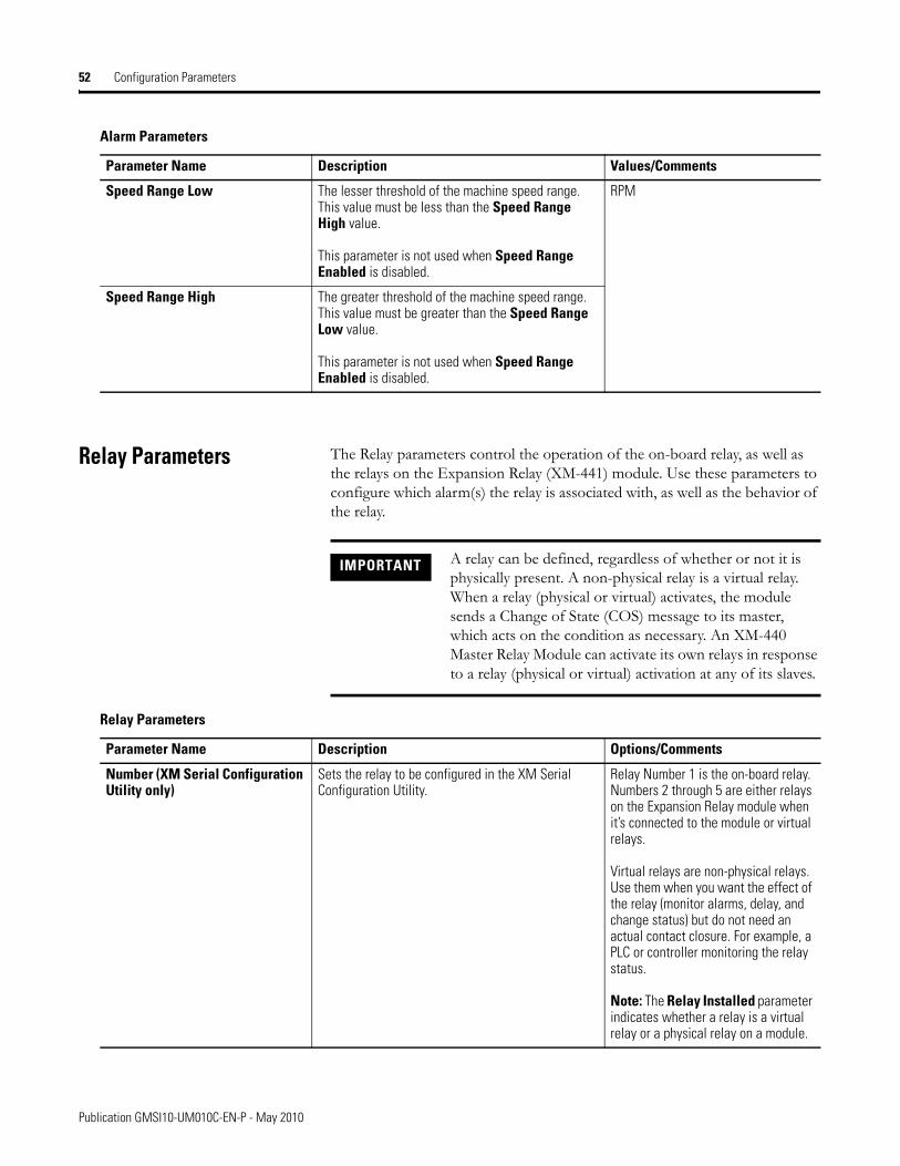
52 Configuration Parameters
Relay Parameters The Relay parameters control the operation of the on-board relay, as well as the relays on the Expansion Relay (XM-441) module. Use these parameters to configure which alarm(s) the relay is associated with, as well as the behavior of the relay.
Speed Range Low
The lesser threshold of the machine speed range. This value must be less than the Speed Range High value.
This parameter is not used when Speed Range Enabled is disabled.
RPM
Speed Range High The greater threshold of the machine speed range. This value must be greater than the Speed Range Low value.
This parameter is not used when Speed Range Enabled is disabled.
Alarm Parameters
Parameter Name Description Values/Comments
IMPORTANT A relay can be defined, regardless of whether or not it is physically present. A non-physical relay is a virtual relay. When a relay (physical or virtual) activates, the module sends a Change of State (COS) message to its master, which acts on the condition as necessary. An XM-440 Master Relay Module can activate its own relays in response to a relay (physical or virtual) activation at any of its slaves.
Relay Parameters
Parameter Name Description Options/Comments
Number (XM Serial Configuration Utility only)
Sets the relay to be configured in the XM Serial Configuration Utility.
Relay Number 1 is the on-board relay. Numbers 2 through 5 are either relays on the Expansion Relay module when it’s connected to the module or virtual relays.
Virtual relays are non-physical relays. Use them when you want the effect of the relay (monitor alarms, delay, and change status) but do not need an actual contact closure. For example, a PLC or controller monitoring the relay status.
Note: The Relay Installed parameter indicates whether a relay is a virtual relay or a physical relay on a module.
Publication GMSI10-UM010C-EN-P - May 2010
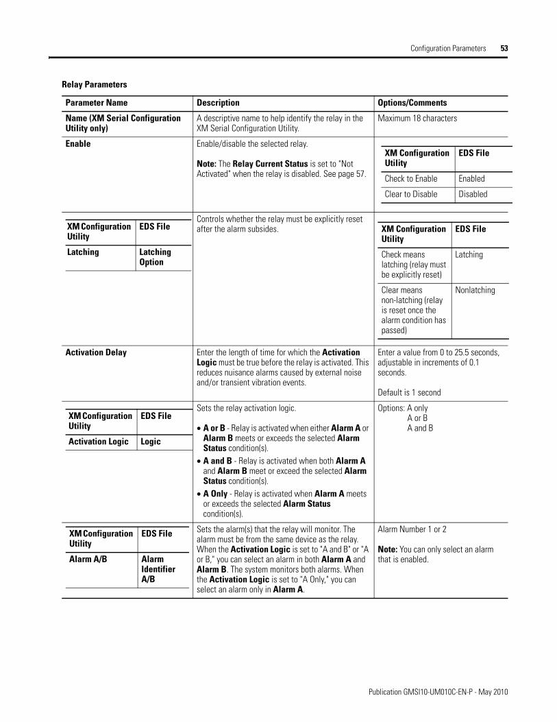
Configuration Parameters 53
Name (XM Serial Configuration Utility only)
A descriptive name to help identify the relay in the XM Serial Configuration Utility.
Maximum 18 characters
Enable Enable/disable the selected relay.
Note: The Relay Current Status is set to "Not Activated" when the relay is disabled. See page 57.
Controls whether the relay must be explicitly reset after the alarm subsides.
Activation Delay Enter the length of time for which the Activation Logic must be true before the relay is activated. This reduces nuisance alarms caused by external noise and/or transient vibration events.
Enter a value from 0 to 25.5 seconds, adjustable in increments of 0.1 seconds.
Default is 1 second
Sets the relay activation logic.
• A or B - Relay is activated when either Alarm A or Alarm B meets or exceeds the selected Alarm Status condition(s).
• A and B - Relay is activated when both Alarm A and Alarm B meet or exceed the selected Alarm Status condition(s).
• A Only - Relay is activated when Alarm A meets or exceeds the selected Alarm Status condition(s).
Options: A onlyA or BA and B
Sets the alarm(s) that the relay will monitor. The alarm must be from the same device as the relay. When the Activation Logic is set to "A and B" or "A or B," you can select an alarm in both Alarm A and Alarm B. The system monitors both alarms. When the Activation Logic is set to "A Only," you can select an alarm only in Alarm A.
Alarm Number 1 or 2
Note: You can only select an alarm that is enabled.
Relay Parameters
Parameter Name Description Options/Comments
XM Configuration Utility
EDS File
Check to Enable Enabled
Clear to Disable Disabled
XM Configuration Utility
EDS File
Latching Latching Option
XM Configuration Utility
EDS File
Check means latching (relay must be explicitly reset)
Latching
Clear means non-latching (relay is reset once the alarm condition has passed)
Nonlatching
XM Configuration Utility
EDS File
Activation Logic Logic
XM Configuration Utility
EDS File
Alarm A/B Alarm Identifier A/B
Publication GMSI10-UM010C-EN-P - May 2010
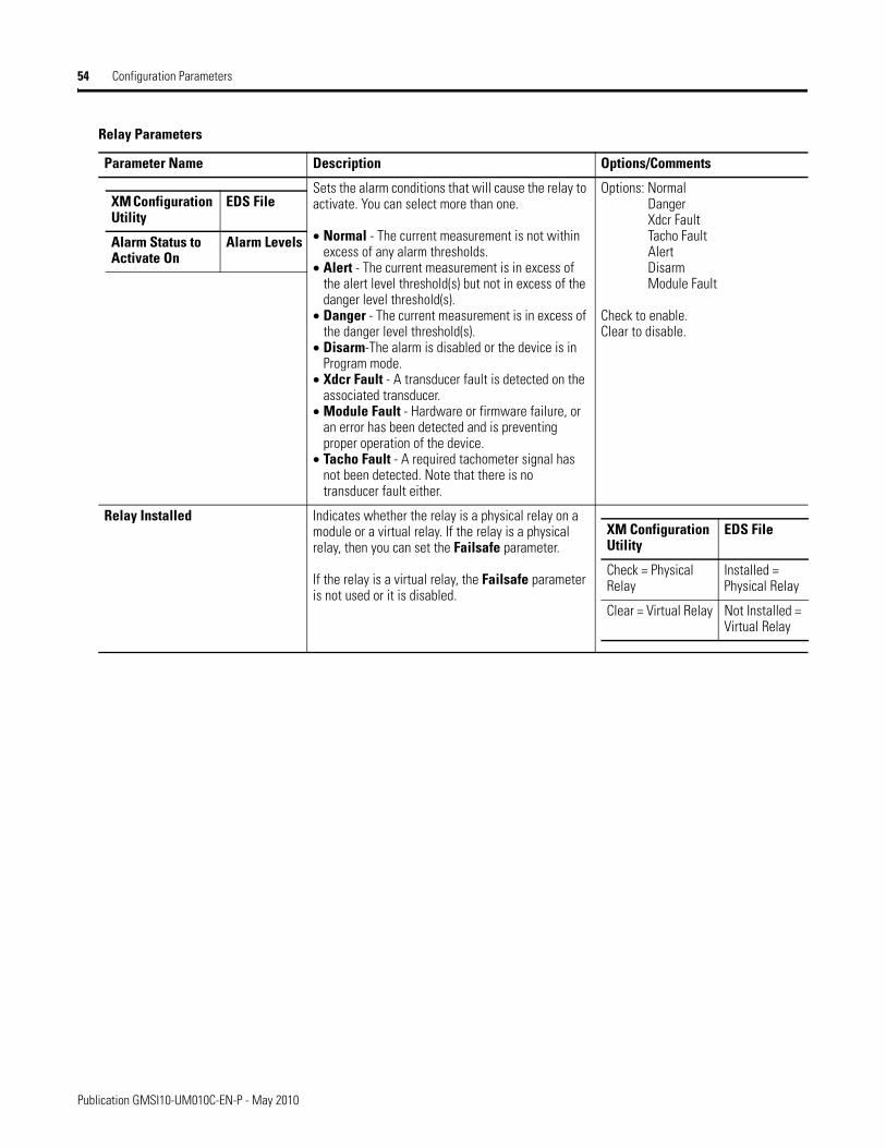
54 Configuration Parameters
Sets the alarm conditions that will cause the relay to activate. You can select more than one.
• Normal - The current measurement is not within excess of any alarm thresholds.
• Alert - The current measurement is in excess of the alert level threshold(s) but not in excess of the danger level threshold(s).
• Danger - The current measurement is in excess of the danger level threshold(s).
• Disarm-The alarm is disabled or the device is in Program mode.
• Xdcr Fault - A transducer fault is detected on the associated transducer.
• Module Fault - Hardware or firmware failure, or an error has been detected and is preventing proper operation of the device.
• Tacho Fault - A required tachometer signal has not been detected. Note that there is no transducer fault either.
Options: NormalDangerXdcr FaultTacho FaultAlertDisarmModule Fault
Check to enable.Clear to disable.
Relay Installed Indicates whether the relay is a physical relay on a module or a virtual relay. If the relay is a physical relay, then you can set the Failsafe parameter.
If the relay is a virtual relay, the Failsafe parameter is not used or it is disabled.
Relay Parameters
Parameter Name Description Options/Comments
XM Configuration Utility
EDS File
Alarm Status to Activate On
Alarm Levels
XM Configuration Utility
EDS File
Check = Physical Relay
Installed = Physical Relay
Clear = Virtual Relay Not Installed = Virtual Relay
Publication GMSI10-UM010C-EN-P - May 2010
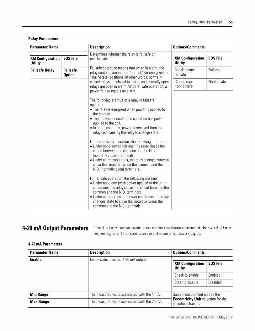
Configuration Parameters 55
4-20 mA Output Parameters The 4-20 mA output parameters define the characteristics of the two 4-20 mA output signals. The parameters are the same for each output.
Determines whether the relay is failsafe or non-failsafe.
Failsafe operation means that when in alarm, the relay contacts are in their "normal," de-energized, or "shelf-state" positions. In other words, normally closed relays are closed in alarm, and normally open relays are open in alarm. With failsafe operation, a power failure equals an alarm.
The following are true of a relay in failsafe operation:• The relay is energized when power is applied to
the module.• The relay in a nonalarmed condition has power
applied to the coil.• In alarm condition, power is removed from the
relay coil, causing the relay to change state.
For non-failsafe operation, the following are true:• Under nonalarm conditions, the relay closes the
circuit between the common and the N.C. (normally closed) terminals.
• Under alarm conditions, the relay changes state to close the circuit between the common and the N.O. (normally open) terminals.
For failsafe operation, the following are true:• Under nonalarm (with power applied to the unit)
conditions, the relay closes the circuit between the common and the N.O. terminals.
• Under alarm or loss-of-power conditions, the relay changes state to close the circuit between the common and the N.C. terminals.
Relay Parameters
Parameter Name Description Options/Comments
XM Configuration Utility
EDS File
Failsafe Relay Failsafe Option
XM Configuration Utility
EDS File
Check means failsafe
Failsafe
Clear means non-failsafe
Nonfailsafe
4-20 mA Parameters
Parameter Name Description Options/Comments
Enable Enables/disables the 4-20 mA output.
Min Range The measured value associated with the 4 mA. Same measurement unit as the Eccentricity Unit selection for the specified channel. Max Range The measured value associated with the 20 mA.
XM Configuration Utility
EDS File
Check to enable Enabled
Clear to disable Disabled
Publication GMSI10-UM010C-EN-P - May 2010
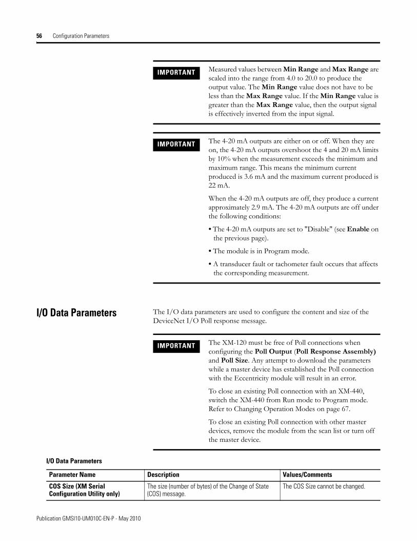
56 Configuration Parameters
I/O Data Parameters The I/O data parameters are used to configure the content and size of the DeviceNet I/O Poll response message.
IMPORTANT Measured values between Min Range and Max Range are scaled into the range from 4.0 to 20.0 to produce the output value. The Min Range value does not have to be less than the Max Range value. If the Min Range value is greater than the Max Range value, then the output signal is effectively inverted from the input signal.
IMPORTANT The 4-20 mA outputs are either on or off. When they are on, the 4-20 mA outputs overshoot the 4 and 20 mA limits by 10% when the measurement exceeds the minimum and maximum range. This means the minimum current produced is 3.6 mA and the maximum current produced is 22 mA.
When the 4-20 mA outputs are off, they produce a current approximately 2.9 mA. The 4-20 mA outputs are off under the following conditions:
• The 4-20 mA outputs are set to "Disable" (see Enable on the previous page).
• The module is in Program mode.
• A transducer fault or tachometer fault occurs that affects the corresponding measurement.
IMPORTANT The XM-120 must be free of Poll connections when configuring the Poll Output (Poll Response Assembly) and Poll Size. Any attempt to download the parameters while a master device has established the Poll connection with the Eccentricity module will result in an error.
To close an existing Poll connection with an XM-440, switch the XM-440 from Run mode to Program mode. Refer to Changing Operation Modes on page 67.
To close an existing Poll connection with other master devices, remove the module from the scan list or turn off the master device.
I/O Data Parameters
Parameter Name Description Values/Comments
COS Size (XM Serial Configuration Utility only)
The size (number of bytes) of the Change of State (COS) message.
The COS Size cannot be changed.
Publication GMSI10-UM010C-EN-P - May 2010
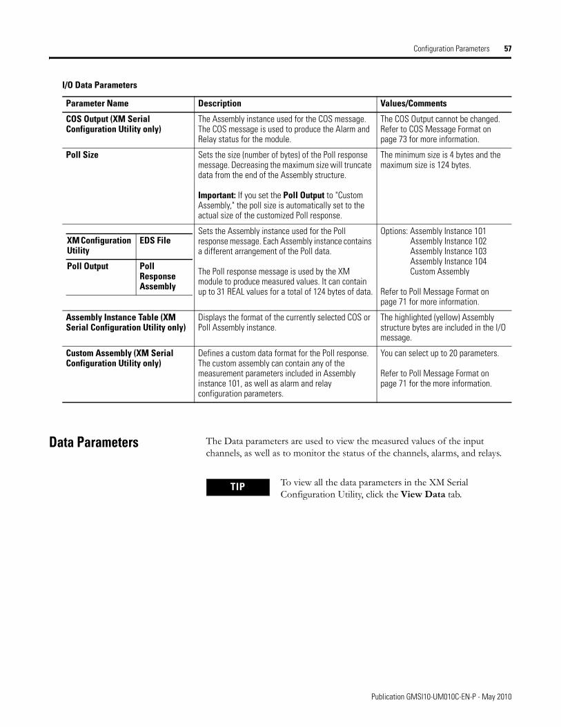
Configuration Parameters 57
Data Parameters The Data parameters are used to view the measured values of the input channels, as well as to monitor the status of the channels, alarms, and relays.
COS Output (XM Serial Configuration Utility only)
The Assembly instance used for the COS message. The COS message is used to produce the Alarm and Relay status for the module.
The COS Output cannot be changed. Refer to COS Message Format on page 73 for more information.
Poll Size Sets the size (number of bytes) of the Poll response message. Decreasing the maximum size will truncate data from the end of the Assembly structure.
Important: If you set the Poll Output to "Custom Assembly," the poll size is automatically set to the actual size of the customized Poll response.
The minimum size is 4 bytes and the maximum size is 124 bytes.
Sets the Assembly instance used for the Poll response message. Each Assembly instance contains a different arrangement of the Poll data.
The Poll response message is used by the XM module to produce measured values. It can contain up to 31 REAL values for a total of 124 bytes of data.
Options: Assembly Instance 101Assembly Instance 102Assembly Instance 103Assembly Instance 104Custom Assembly
Refer to Poll Message Format on page 71 for more information.
Assembly Instance Table (XM Serial Configuration Utility only)
Displays the format of the currently selected COS or Poll Assembly instance.
The highlighted (yellow) Assembly structure bytes are included in the I/O message.
Custom Assembly (XM Serial Configuration Utility only)
Defines a custom data format for the Poll response. The custom assembly can contain any of the measurement parameters included in Assembly instance 101, as well as alarm and relay configuration parameters.
You can select up to 20 parameters.
Refer to Poll Message Format on page 71 for the more information.
I/O Data Parameters
Parameter Name Description Values/Comments
XM Configuration Utility
EDS File
Poll Output Poll Response Assembly
TIP To view all the data parameters in the XM Serial Configuration Utility, click the View Data tab.
Publication GMSI10-UM010C-EN-P - May 2010
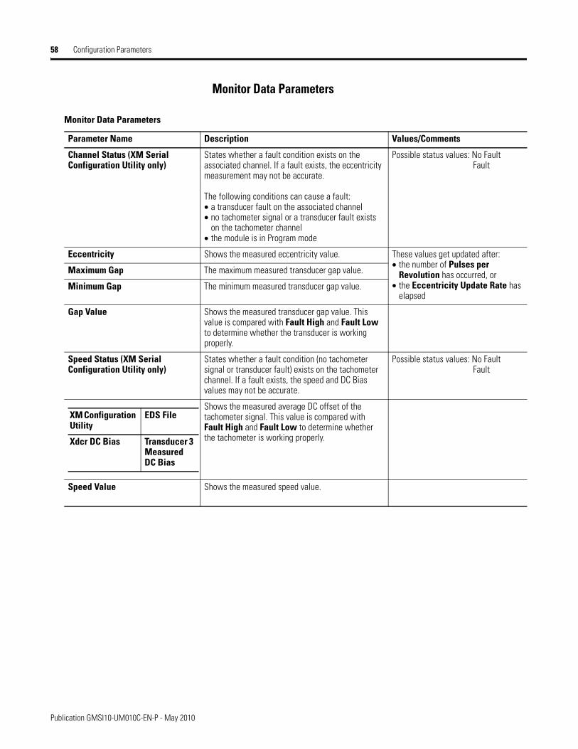
58 Configuration Parameters
Monitor Data Parameters
Monitor Data Parameters
Parameter Name Description Values/Comments
Channel Status (XM Serial Configuration Utility only)
States whether a fault condition exists on the associated channel. If a fault exists, the eccentricity measurement may not be accurate.
The following conditions can cause a fault:• a transducer fault on the associated channel• no tachometer signal or a transducer fault exists
on the tachometer channel• the module is in Program mode
Possible status values: No FaultFault
Eccentricity Shows the measured eccentricity value. These values get updated after:• the number of Pulses per
Revolution has occurred, or• the Eccentricity Update Rate has
elapsed
Maximum Gap The maximum measured transducer gap value.
Minimum Gap The minimum measured transducer gap value.
Gap Value Shows the measured transducer gap value. This value is compared with Fault High and Fault Low to determine whether the transducer is working properly.
Speed Status (XM Serial Configuration Utility only)
States whether a fault condition (no tachometer signal or transducer fault) exists on the tachometer channel. If a fault exists, the speed and DC Bias values may not be accurate.
Possible status values: No FaultFault
Shows the measured average DC offset of the tachometer signal. This value is compared with Fault High and Fault Low to determine whether the tachometer is working properly.
Speed Value Shows the measured speed value.
XM Configuration Utility
EDS File
Xdcr DC Bias Transducer 3 Measured DC Bias
Publication GMSI10-UM010C-EN-P - May 2010
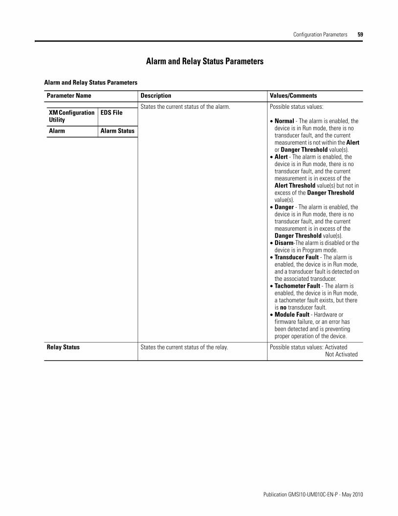
Configuration Parameters 59
Alarm and Relay Status Parameters
Alarm and Relay Status Parameters
Parameter Name Description Values/Comments
States the current status of the alarm. Possible status values:
• Normal - The alarm is enabled, the device is in Run mode, there is no transducer fault, and the current measurement is not within the Alert or Danger Threshold value(s).
• Alert - The alarm is enabled, the device is in Run mode, there is no transducer fault, and the current measurement is in excess of the Alert Threshold value(s) but not in excess of the Danger Threshold value(s).
• Danger - The alarm is enabled, the device is in Run mode, there is no transducer fault, and the current measurement is in excess of the Danger Threshold value(s).
• Disarm-The alarm is disabled or the device is in Program mode.
• Transducer Fault - The alarm is enabled, the device is in Run mode, and a transducer fault is detected on the associated transducer.
• Tachometer Fault - The alarm is enabled, the device is in Run mode, a tachometer fault exists, but there is no transducer fault.
• Module Fault - Hardware or firmware failure, or an error has been detected and is preventing proper operation of the device.
Relay Status States the current status of the relay. Possible status values: ActivatedNot Activated
XM Configuration Utility
EDS File
Alarm Alarm Status
Publication GMSI10-UM010C-EN-P - May 2010
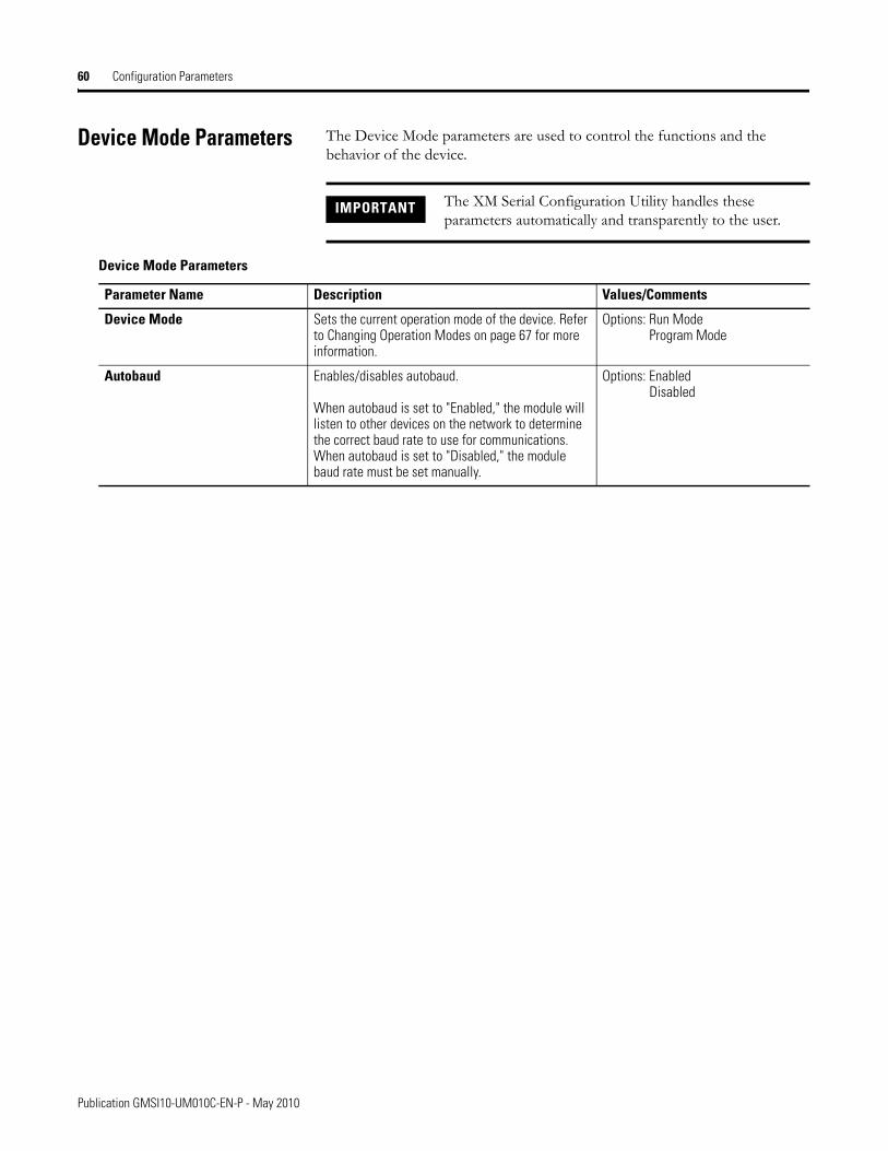
60 Configuration Parameters
Device Mode Parameters The Device Mode parameters are used to control the functions and the behavior of the device.
IMPORTANT The XM Serial Configuration Utility handles these parameters automatically and transparently to the user.
Device Mode Parameters
Parameter Name Description Values/Comments
Device Mode Sets the current operation mode of the device. Refer to Changing Operation Modes on page 67 for more information.
Options: Run ModeProgram Mode
Autobaud Enables/disables autobaud.
When autobaud is set to "Enabled," the module will listen to other devices on the network to determine the correct baud rate to use for communications. When autobaud is set to "Disabled," the module baud rate must be set manually.
Options: EnabledDisabled
Publication GMSI10-UM010C-EN-P - May 2010
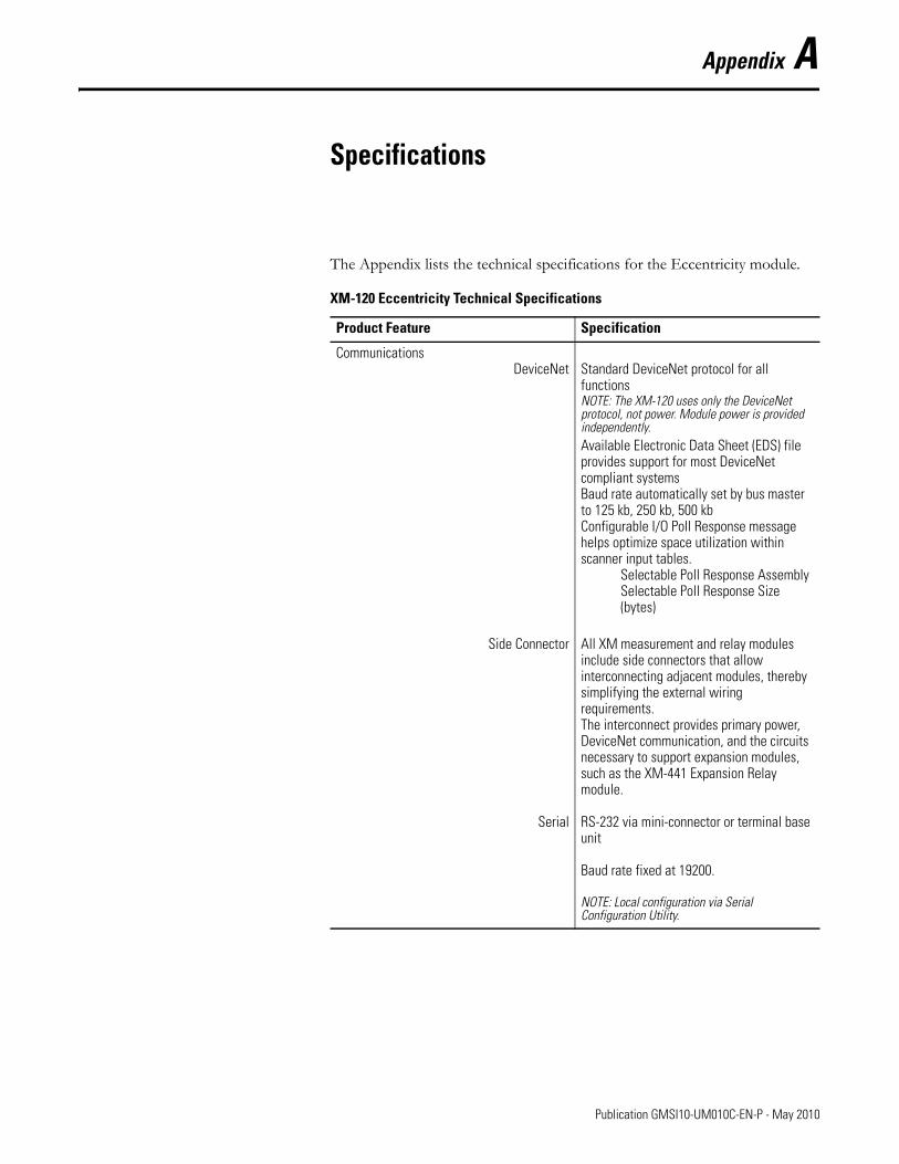
Appendix A
Specifications
The Appendix lists the technical specifications for the Eccentricity module.
XM-120 Eccentricity Technical Specifications
Product Feature Specification
CommunicationsDeviceNet
Side Connector
Serial
Standard DeviceNet protocol for all functionsNOTE: The XM-120 uses only the DeviceNet protocol, not power. Module power is provided independently.Available Electronic Data Sheet (EDS) file provides support for most DeviceNet compliant systemsBaud rate automatically set by bus master to 125 kb, 250 kb, 500 kbConfigurable I/O Poll Response message helps optimize space utilization within scanner input tables.
Selectable Poll Response AssemblySelectable Poll Response Size (bytes)
All XM measurement and relay modules include side connectors that allow interconnecting adjacent modules, thereby simplifying the external wiring requirements.The interconnect provides primary power, DeviceNet communication, and the circuits necessary to support expansion modules, such as the XM-441 Expansion Relay module.
RS-232 via mini-connector or terminal base unit
Baud rate fixed at 19200.
NOTE: Local configuration via Serial Configuration Utility.
61 Publication GMSI10-UM010C-EN-P - May 2010
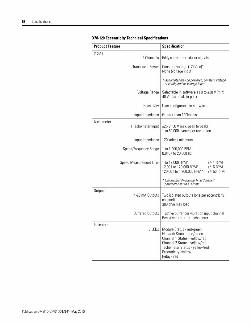
62 Specifications
Inputs2 Channels
Transducer Power
Voltage Range
Sensitivity
Input Impedance
Eddy current transducer signals
Constant voltage (+24V dc)*None (voltage input)
*Tachometer may be powered, constant voltage, or configured as voltage input.
Selectable in software as 0 to ±20 V (min) 40 V max. peak-to-peak
User configurable in software
Greater than 100kohms
Tachometer1 Tachometer Input
Input Impedance
Speed/Frequency Range
Speed Measurement Error
±25 V (50 V max. peak to peak)1 to 50,000 events per revolution
120 kohms minimum
1 to 1,200,000 RPM0.0167 to 20,000 Hz
1 to 12,000 RPM* +/- 1 RPM12,001 to 120,000 RPM* +/- 6 RPM120,001 to 1,200,000 RPM* +/- 50 RPM
* Exponential Averaging Time Constant parameter set to ≥ 120ms
Outputs4-20 mA Outputs
Buffered Outputs
Two isolated outputs (one per eccentricity channel) 300 ohm max load
1 active buffer per vibration input channelResistive buffer for tachometer
Indicators7 LEDs Module Status - red/green
Network Status - red/greenChannel 1 Status - yellow/redChannel 2 Status - yellow/redTachometer Status - yellow/redEccentricity -yellowRelay - red
XM-120 Eccentricity Technical Specifications
Product Feature Specification
Publication GMSI10-UM010C-EN-P - May 2010
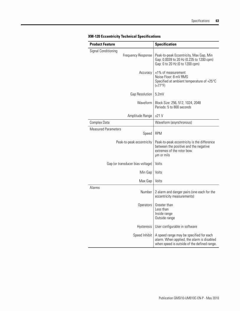
Specifications 63
Signal ConditioningFrequency Response
Accuracy
Gap Resolution
Waveform
Amplitude Range
Peak-to-peak Eccentricity, Max Gap, Min Gap: 0.0039 to 20 Hz (0.235 to 1200 cpm) Gap: 0 to 20 Hz (0 to 1200 cpm)
±1% of measurementNoise Floor: 8 mV RMSSpecified at ambient temperature of +25°C (+77°F)
5.2mV
Block Size: 256, 512, 1024, 2048Periods: 5 to 800 seconds
±21 V
Complex Data Waveform (asynchronous)
Measured ParametersSpeed
Peak-to-peak eccentricity
Gap (or transducer bias voltage)
Min Gap
Max Gap
RPM
Peak-to-peak eccentricity is the difference between the positive and the negative extremes of the rotor bow.µm or mils
Volts
Volts
Volts
AlarmsNumber
Operators
Hysteresis
Speed Inhibit
2 alarm and danger pairs (one each for the eccentricity measurements)
Greater thanLess thanInside rangeOutside range
User configurable in software
A speed range may be specified for each alarm. When applied, the alarm is disabled when speed is outside of the defined range.
XM-120 Eccentricity Technical Specifications
Product Feature Specification
Publication GMSI10-UM010C-EN-P - May 2010
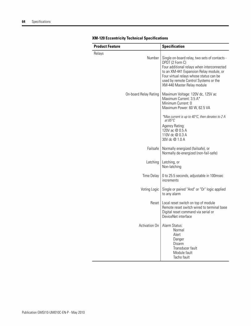
64 Specifications
RelaysNumber
On-board Relay Rating
Failsafe
Latching
Time Delay
Voting Logic
Reset
Activation On
Single on-board relay, two sets of contacts - DPDT (2 Form C)Four additional relays when interconnected to an XM-441 Expansion Relay module, or Four virtual relays whose status can be used by remote Control Systems or the XM-440 Master Relay module
Maximum Voltage: 120V dc, 125V acMaximum Current: 3.5 A*Minimum Current: 0Maximum Power: 60 W, 62.5 VA
*Max current is up to 40°C, then derates to 2 A at 65°C
Agency Rating:120V ac @ 0.5 A110V dc @ 0.3 A30V dc @ 1.0 A
Normally energized (failsafe), orNormally de-energized (non-fail-safe)
Latching, orNon-latching
0 to 25.5 seconds, adjustable in 100msec increments
Single or paired "And" or "Or" logic applied to any alarm
Local reset switch on top of moduleRemote reset switch wired to terminal baseDigital reset command via serial or DeviceNet interface
Alarm Status:NormalAlertDangerDisarmTransducer faultModule faultTacho fault
XM-120 Eccentricity Technical Specifications
Product Feature Specification
Publication GMSI10-UM010C-EN-P - May 2010
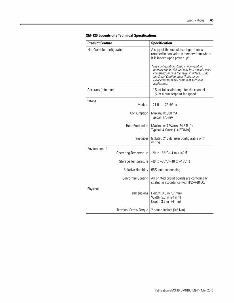
Specifications 65
Non-Volatile Configuration A copy of the module configuration is retained in non-volatile memory from where it is loaded upon power up*.
*The configuration stored in non-volatile memory can be deleted only by a module-reset command sent via the serial interface, using the Serial Configuration Utility, or via DeviceNet from any compliant software application.
Accuracy (minimum) ±1% of full scale range for the channel±1% of alarm setpoint for speed
Power Module
Consumption
Heat Production
Transducer
+21.6 to +26.4V dc
Maximum: 300 mATypical: 175 mA
Maximum: 7 Watts (24 BTU/hr)Typical: 4 Watts (14 BTU/hr)
Isolated 24V dc, user configurable with wiring
EnvironmentalOperating Temperature
Storage Temperature
Relative Humidity
Conformal Coating
-20 to +65°C (-4 to +149°F)
-40 to +85°C (-40 to +185°F)
95% non-condensing
All printed circuit boards are conformally coated in accordance with IPC-A-610C.
PhysicalDimensions
Terminal Screw Torque
Height: 3.8 in (97 mm)Width: 3.7 in (94 mm)Depth: 3.7 in (94 mm)
7 pound-inches (0.6 Nm)
XM-120 Eccentricity Technical Specifications
Product Feature Specification
Publication GMSI10-UM010C-EN-P - May 2010
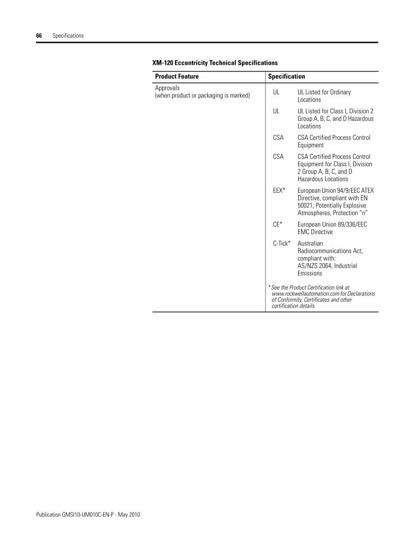
66 Specifications
Approvals(when product or packaging is marked)
*See the Product Certification link at www.rockwellautomation.com for Declarations of Conformity, Certificates and other certification details.
XM-120 Eccentricity Technical Specifications
Product Feature Specification
UL UL Listed for Ordinary Locations
UL UL Listed for Class I, Division 2 Group A, B, C, and D Hazardous Locations
CSA CSA Certified Process Control Equipment
CSA CSA Certified Process Control Equipment for Class I, Division 2 Group A, B, C, and D Hazardous Locations
EEX* European Union 94/9/EEC ATEX Directive, compliant with EN 50021; Potentially Explosive Atmospheres, Protection “n”
CE* European Union 89/336/EEC EMC Directive
C-Tick* Australian Radiocommunications Act, compliant with:AS/NZS 2064, Industrial Emissions
Publication GMSI10-UM010C-EN-P - May 2010
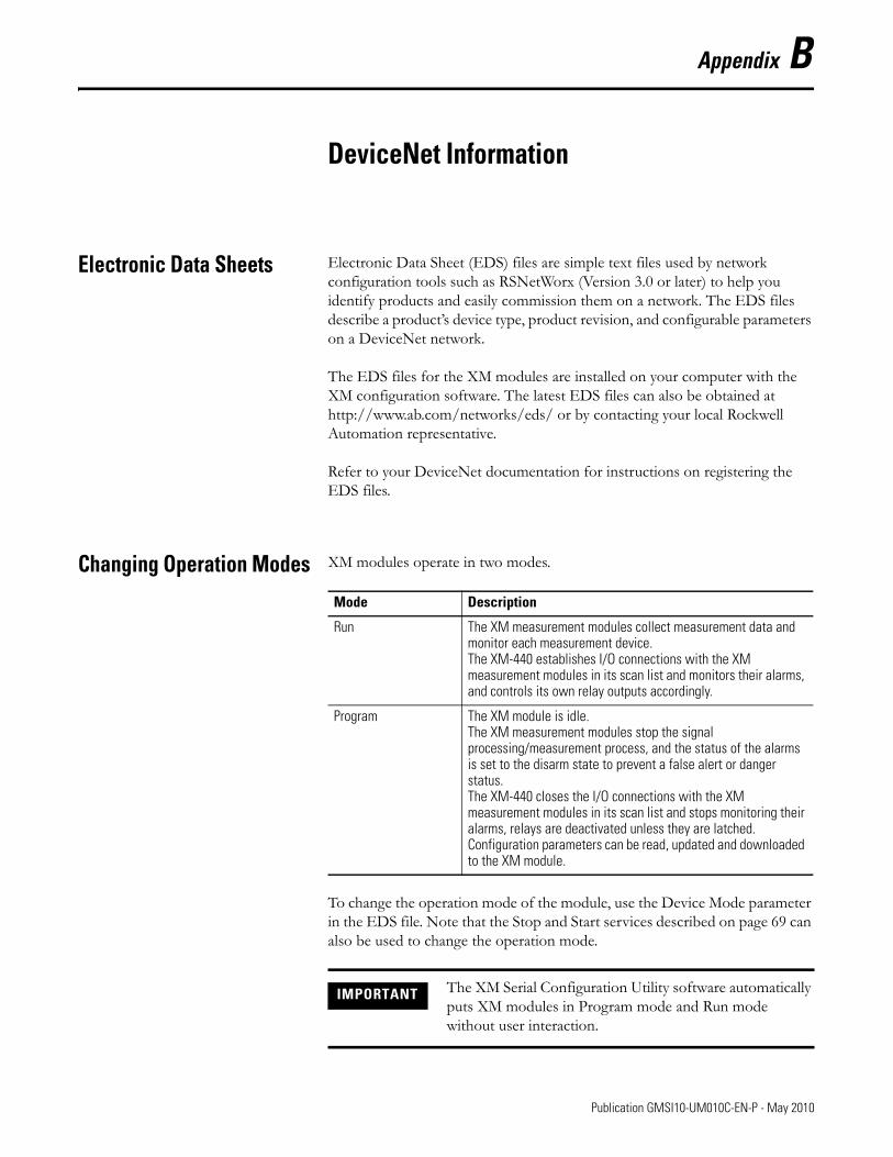
Appendix B
DeviceNet Information
Electronic Data Sheets Electronic Data Sheet (EDS) files are simple text files used by network configuration tools such as RSNetWorx (Version 3.0 or later) to help you identify products and easily commission them on a network. The EDS files describe a product’s device type, product revision, and configurable parameters on a DeviceNet network.
The EDS files for the XM modules are installed on your computer with the XM configuration software. The latest EDS files can also be obtained at http://www.ab.com/networks/eds/ or by contacting your local Rockwell Automation representative.
Refer to your DeviceNet documentation for instructions on registering the EDS files.
Changing Operation Modes XM modules operate in two modes.
To change the operation mode of the module, use the Device Mode parameter in the EDS file. Note that the Stop and Start services described on page 69 can also be used to change the operation mode.
Mode Description
Run The XM measurement modules collect measurement data and monitor each measurement device. The XM-440 establishes I/O connections with the XM measurement modules in its scan list and monitors their alarms, and controls its own relay outputs accordingly.
Program The XM module is idle.The XM measurement modules stop the signal processing/measurement process, and the status of the alarms is set to the disarm state to prevent a false alert or danger status. The XM-440 closes the I/O connections with the XM measurement modules in its scan list and stops monitoring their alarms, relays are deactivated unless they are latched.Configuration parameters can be read, updated and downloaded to the XM module.
IMPORTANT The XM Serial Configuration Utility software automatically puts XM modules in Program mode and Run mode without user interaction.
67 Publication GMSI10-UM010C-EN-P - May 2010

68 DeviceNet Information
Transition to Program Mode
Parameter values can only be downloaded to an XM module while the module is in Program mode. Any attempt to download a parameter value while the module is in Run mode will result in a Device State Conflict error.
To transition an XM module from Run mode to Program mode on a DeviceNet network, set the Device Mode parameter to "Program mode" and click Apply. Note that you cannot change any other parameter until you have downloaded the Program mode parameter.
Refer to your DeviceNet documentation for specific instructions on editing EDS device parameters.
Transition to Run Mode
In order to collect data and monitor measurement devices, XM modules must be in Run mode. To transition an XM module from Program mode to Run mode on a DeviceNet network, set the Device Mode parameter to "Run mode" and click Apply.
Refer to your DeviceNet documentation for specific instructions on editing EDS device parameters.
TIP The Module Status indicator flashes green when the module is in Program mode.
TIP You can also use the Stop service described on page 69 to transition XM modules to Program mode.
TIP The Module Status indicator is solid green when the module is in Run mode.
TIP You can also use the Start service described on page 69 to transition XM modules to Run mode.
Publication GMSI10-UM010C-EN-P - May 2010
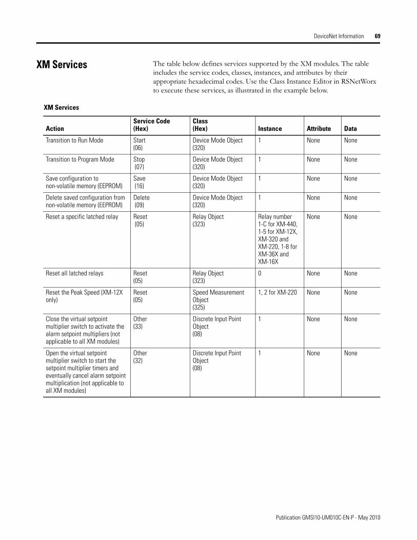
DeviceNet Information 69
XM Services The table below defines services supported by the XM modules. The table includes the service codes, classes, instances, and attributes by their appropriate hexadecimal codes. Use the Class Instance Editor in RSNetWorx to execute these services, as illustrated in the example below.
XM Services
ActionService Code(Hex)
Class(Hex) Instance Attribute Data
Transition to Run Mode Start(06)
Device Mode Object (320)
1 None None
Transition to Program Mode Stop (07)
Device Mode Object(320)
1 None None
Save configuration to non-volatile memory (EEPROM)
Save (16)
Device Mode Object(320)
1 None None
Delete saved configuration from non-volatile memory (EEPROM)
Delete (09)
Device Mode Object (320)
1 None None
Reset a specific latched relay Reset (05)
Relay Object (323)
Relay number 1-C for XM-440, 1-5 for XM-12X, XM-320 and XM-220, 1-8 for XM-36X and XM-16X
None None
Reset all latched relays Reset (05)
Relay Object(323)
0 None None
Reset the Peak Speed (XM-12X only)
Reset (05)
Speed Measurement Object(325)
1, 2 for XM-220 None None
Close the virtual setpoint multiplier switch to activate the alarm setpoint multipliers (not applicable to all XM modules)
Other(33)
Discrete Input Point Object(08)
1 None None
Open the virtual setpoint multiplier switch to start the setpoint multiplier timers and eventually cancel alarm setpoint multiplication (not applicable to all XM modules)
Other (32)
Discrete Input Point Object(08)
1 None None
Publication GMSI10-UM010C-EN-P - May 2010
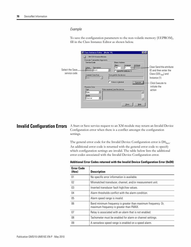
70 DeviceNet Information
Example
To save the configuration parameters to the non-volatile memory (EEPROM), fill in the Class Instance Editor as shown below.
Invalid Configuration Errors A Start or Save service request to an XM module may return an Invalid Device Configuration error when there is a conflict amongst the configuration settings.
The general error code for the Invalid Device Configuration error is D0hex. An additional error code is returned with the general error code to specify which configuration settings are invalid. The table below lists the additional error codes associated with the Invalid Device Configuration error.
Select the Saveservice code
Clear Send the attribute ID and then enter the Class (320 hex) and Instance (1)
Click Execute to initiate the action
Additional Error Codes returned with the Invalid Device Configuration Error (0xD0)
Error Code (Hex) Description
01 No specific error information is available.
02 Mismatched transducer, channel, and/or measurement unit.
03 Inverted transducer fault high/low values.
04 Alarm thresholds conflict with the alarm condition.
05 Alarm speed range is invalid.
06 Band minimum frequency is greater than maximum frequency. Or, maximum frequency is greater than FMAX.
07 Relay is associated with an alarm that is not enabled.
08 Tachometer must be enabled for alarm or channel settings.
09 A senseless speed range is enabled on a speed alarm.
Publication GMSI10-UM010C-EN-P - May 2010

DeviceNet Information 71
Eccentricity I/O Message Formats
The Eccentricity module supports Poll and Change of State (COS) I/O messages. The Poll response message is used by the XM module to produce measured values and the COS message is used to produce the Alarm and Relay Status.
Poll Message Format
The Eccentricity module Poll request message contains no data. The Poll response message can contain up to 31 REAL values for a total of 124 bytes.
The Eccentricity module provides four pre-defined (static) data formats of the Poll response, as defined in Assembly instance 101–104. It also provides a dynamic Assembly instance, instance 199, with which you can define a custom data format for the Poll response. The dynamic Assembly instance can contain any of the measurement parameters included in Assembly instance 101, as well as several of the alarm and relay configuration parameters.
The default Assembly instance is 101 and the default size is 36 bytes. You can change the Assembly instance and define the custom Assembly instance using the configuration software. Refer to I/O Data Parameters on page 56 for details.
0A Too many alarms associated with a single measurement.
0B Invalid node address in the alarm list.
0C Too many alarms in the alarm list. Or, no alarms in the alarm list.
0D Alarm levels cannot be zero for alarms that are enabled.
0E Too many slaves in the scanner’s input data table.
0F The FMAX and Number of Lines do not yield correct vector calculations.
10 Phase (vector) alarms prohibited with synchronous sampling and more than 1 tachometer pulse per revolution.
11 Can’t have order based band on asynchronous channel.
12 Unsupported Sensor Type and Channel ID combination.
13 Invalid Alarm Type for the associated measurement ID.
14 Synchronous sampling is required for alarm on synchronous measurements.
15 Integration is not supported with the Bypass High Pass Filter option.
Additional Error Codes returned with the Invalid Device Configuration Error (0xD0)
Error Code (Hex) Description
Publication GMSI10-UM010C-EN-P - May 2010
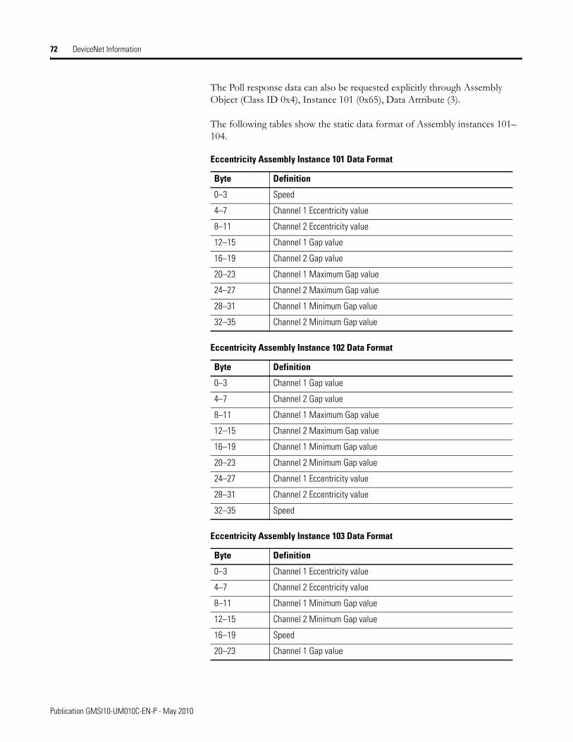
72 DeviceNet Information
The Poll response data can also be requested explicitly through Assembly Object (Class ID 0x4), Instance 101 (0x65), Data Attribute (3).
The following tables show the static data format of Assembly instances 101–104.
Eccentricity Assembly Instance 101 Data Format
Byte Definition
0–3 Speed
4–7 Channel 1 Eccentricity value
8–11 Channel 2 Eccentricity value
12–15 Channel 1 Gap value
16–19 Channel 2 Gap value
20–23 Channel 1 Maximum Gap value
24–27 Channel 2 Maximum Gap value
28–31 Channel 1 Minimum Gap value
32–35 Channel 2 Minimum Gap value
Eccentricity Assembly Instance 102 Data Format
Byte Definition
0–3 Channel 1 Gap value
4–7 Channel 2 Gap value
8–11 Channel 1 Maximum Gap value
12–15 Channel 2 Maximum Gap value
16–19 Channel 1 Minimum Gap value
20–23 Channel 2 Minimum Gap value
24–27 Channel 1 Eccentricity value
28–31 Channel 2 Eccentricity value
32–35 Speed
Eccentricity Assembly Instance 103 Data Format
Byte Definition
0–3 Channel 1 Eccentricity value
4–7 Channel 2 Eccentricity value
8–11 Channel 1 Minimum Gap value
12–15 Channel 2 Minimum Gap value
16–19 Speed
20–23 Channel 1 Gap value
Publication GMSI10-UM010C-EN-P - May 2010
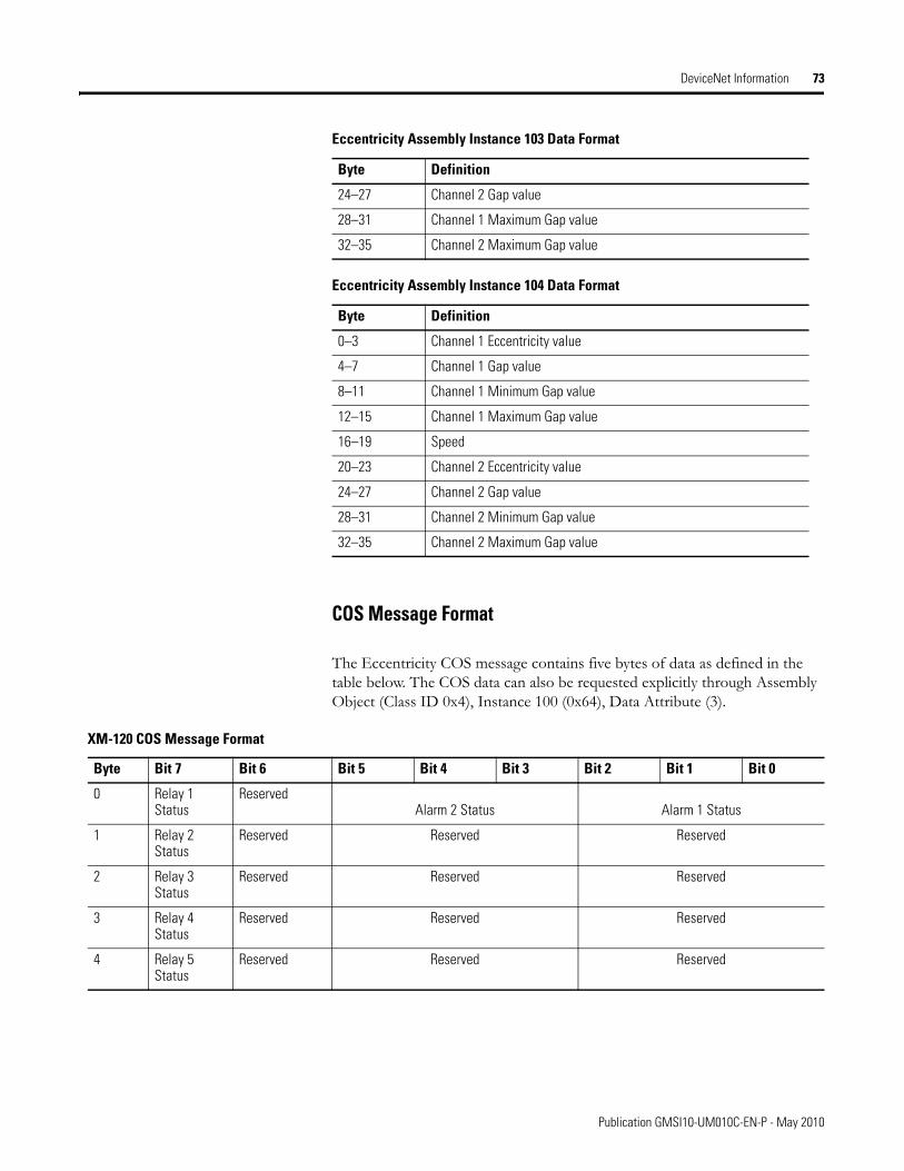
DeviceNet Information 73
COS Message Format
The Eccentricity COS message contains five bytes of data as defined in the table below. The COS data can also be requested explicitly through Assembly Object (Class ID 0x4), Instance 100 (0x64), Data Attribute (3).
24–27 Channel 2 Gap value
28–31 Channel 1 Maximum Gap value
32–35 Channel 2 Maximum Gap value
Eccentricity Assembly Instance 104 Data Format
Byte Definition
0–3 Channel 1 Eccentricity value
4–7 Channel 1 Gap value
8–11 Channel 1 Minimum Gap value
12–15 Channel 1 Maximum Gap value
16–19 Speed
20–23 Channel 2 Eccentricity value
24–27 Channel 2 Gap value
28–31 Channel 2 Minimum Gap value
32–35 Channel 2 Maximum Gap value
Eccentricity Assembly Instance 103 Data Format
Byte Definition
XM-120 COS Message Format
Byte Bit 7 Bit 6 Bit 5 Bit 4 Bit 3 Bit 2 Bit 1 Bit 0
0 Relay 1 Status
ReservedAlarm 2 Status Alarm 1 Status
1 Relay 2 Status
Reserved Reserved Reserved
2 Relay 3 Status
Reserved Reserved Reserved
3 Relay 4 Status
Reserved Reserved Reserved
4 Relay 5 Status
Reserved Reserved Reserved
Publication GMSI10-UM010C-EN-P - May 2010

74 DeviceNet Information
XM Status Values
The following tables describe the XM Status values that are included in the COS messages.
ADR for XM Modules Automatic Device Replacement (ADR) is a feature of an Allen-Bradley DeviceNet scanner. It provides a means for replacing a failed device with a new unit, and having the device configuration data set automatically. Upon replacing a failed device with a new unit, the ADR scanner automatically downloads the configuration data and sets the node address.
ADR can be used with XM modules but keep the following in mind when setting up the XM modules.
Alarm Status Descriptions
Alarm Status Value Description
0 Normal
1 Alert
2 Danger
3 Disarm
4 Transducer Fault (Sensor OOR)
5 Module Fault
6 Tachometer Fault
7 Reserved
Relay Status Descriptions
Relay Status Value Description
0 Not Activated
1 Activated
IMPORTANT It is recommended that ADR not be used in safety related applications. If the failure of the ADR server, and a subsequent power cycle, would result in the loss of protection for a machine, then ADR should not be implemented.
Publication GMSI10-UM010C-EN-P - May 2010
DeviceNet Information 75
• The ADR scanner can not download the configuration data to an XM module if the module has a saved configuration in its non-volatile memory. This happens because the saved configuration is restored and the module enters Run mode when the power is cycled. (Configuration parameters cannot be downloaded while an XM module is in Run mode.) XM modules must be in Program mode for the ADR configuration to be downloaded and this occurs only when there is no saved configuration.
• An XM module will enter Run mode automatically after the ADR scanner restores the module’s configuration only if the module is in Run mode at the time the configuration is saved to the scanner. If the module is in Program mode when the configuration is saved, then the module will remain in Program mode after the configuration is downloaded by the ADR scanner.
• The ADR scanner saves and restores only the configuration parameters contained in the module’s EDS file. Some XM parameters are not included in the EDS file because they are not supported by either the EDS specification or the tools that read the EDS files, for example RSNetWorx for DeviceNet. These configuration parameters will not be restored with ADR.
Below is a list of the configuration parameters that are not included in the EDS file and can not be saved or restored with ADR.
– Channel Name – Tachometer Name– Alarm Name– Relay Name– All Triggered Trend related parameters
TIP To delete a saved configuration from non-volatile memory, use the Delete service in RSNetWorx for DeviceNet or perform the following steps in the XM Serial Configuration Utility.
1. Save the current configuration to a file. From the File menu, click Save As and enter a file name for the configuration.
2. Reset the module to factory defaults. Click the Module tab and click the Reset button.
3. Reload the saved configuration. From the File menu, click Open and select the configuration file.
4. Make certain to disable auto save. From the Device menu, clear the Auto Save Configuration check mark.
Publication GMSI10-UM010C-EN-P - May 2010

76 DeviceNet Information
– All SU/CD Trend related parameters – Custom Assembly structure (see page 56)
• The ADR and trigger group functions cannot be used together. A module can have only one primary master so a module cannot be both configured for ADR and included in a trigger group. The ADR scanner must be the primary master for the modules configured for ADR. The XM-440 Master Relay module must be the primary master for modules included in a trigger group.
Publication GMSI10-UM010C-EN-P - May 2010

Appendix C
DeviceNet Objects
Appendix C provides information on the DeviceNet objects supported by the Eccentricity module.
For information about See page
Identity Object (Class ID 01H) 78
DeviceNet Object (Class ID 03H) 80
Assembly Object (Class ID 04H) 81
Connection Object (Class ID 05H) 86
Analog Input Point Object (Class ID 0AH) 88
Parameter Object (Class ID 0FH) 90
Acknowledge Handler Object (Class ID 2BH) 93
Alarm Object (Class ID 31DH) 94
Device Mode Object (Class ID 320H) 96
Relay Object (Class ID 323H) 97
Spectrum Waveform Measurement Object (Class ID 324H) 99
Speed Measurement Object (Class ID 325H) 102
Tachometer Channel Object (Class ID 326H) 103
Transducer Object (Class ID 328H) 105
4-20 mA Output Object (Class ID 32AH) 106
TIP Refer to the DeviceNet specification for more information about DeviceNet objects. Information about the DeviceNet specification is available on the ODVA web site (http://www.odva.org).
77 Publication GMSI10-UM010C-EN-P - May 2010
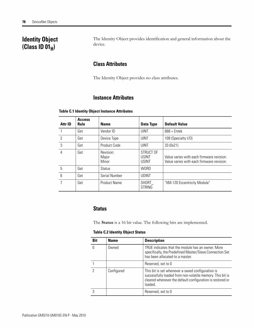
78 DeviceNet Objects
Identity Object(Class ID 01H)
The Identity Object provides identification and general information about the device.
Class Attributes
The Identity Object provides no class attributes.
Instance Attributes
Status
The Status is a 16 bit value. The following bits are implemented.
Table C.1 Identity Object Instance Attributes
Attr IDAccess Rule Name Data Type Default Value
1 Get Vendor ID UINT 668 = Entek
2 Get Device Type UINT 109 (Specialty I/O)
3 Get Product Code UINT 33 (0x21)
4 Get Revision:MajorMinor
STRUCT OF USINTUSINT
Value varies with each firmware revision.Value varies with each firmware revision.
5 Get Status WORD
6 Get Serial Number UDINT
7 Get Product Name SHORT_STRING
"XM-120 Eccentricity Module"
Table C.2 Identity Object Status
Bit Name Description
0 Owned TRUE indicates that the module has an owner. More specifically, the Predefined Master/Slave Connection Set has been allocated to a master.
1 Reserved, set to 0
2 Configured This bit is set whenever a saved configuration is successfully loaded from non-volatile memory. This bit is cleared whenever the default configuration is restored or loaded.
3 Reserved, set to 0
Publication GMSI10-UM010C-EN-P - May 2010
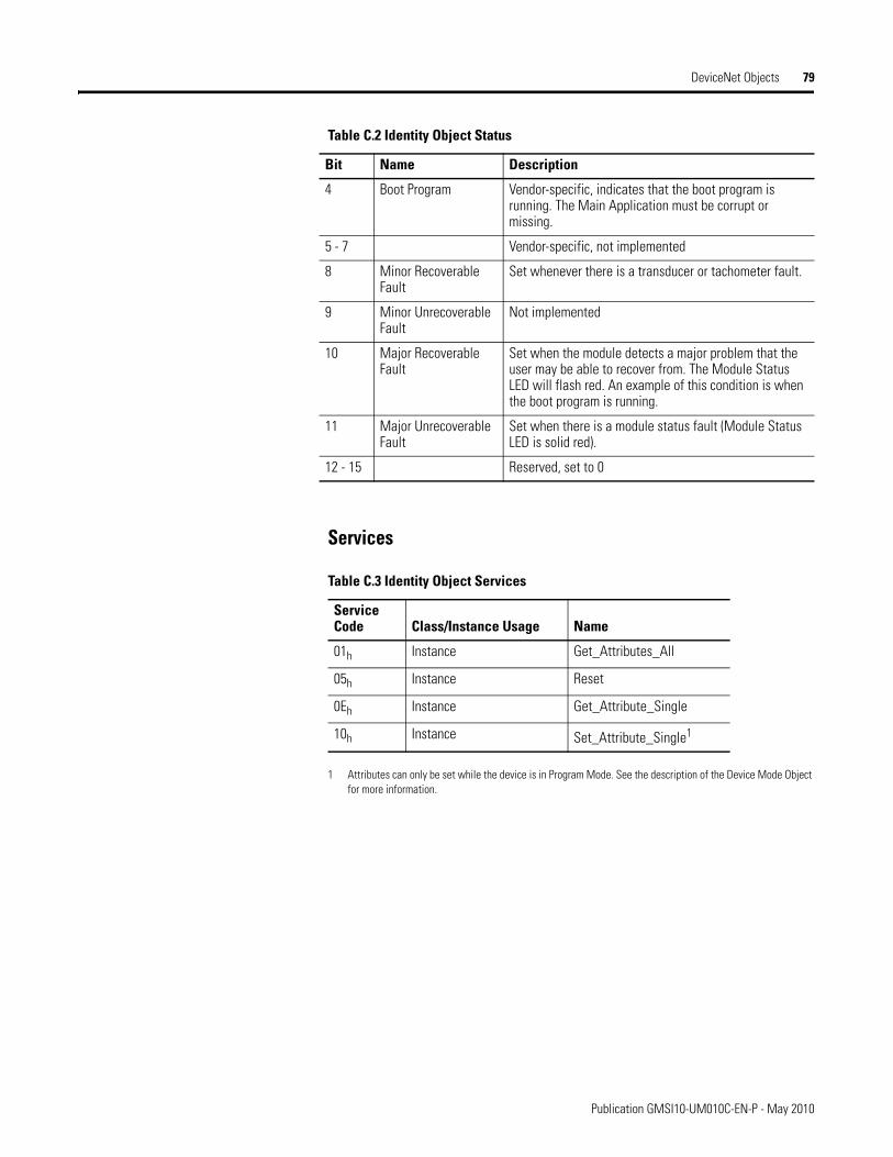
DeviceNet Objects 79
Services
1 Attributes can only be set while the device is in Program Mode. See the description of the Device Mode Object for more information.
4 Boot Program Vendor-specific, indicates that the boot program is running. The Main Application must be corrupt or missing.
5 - 7 Vendor-specific, not implemented
8 Minor Recoverable Fault
Set whenever there is a transducer or tachometer fault.
9 Minor Unrecoverable Fault
Not implemented
10 Major Recoverable Fault
Set when the module detects a major problem that the user may be able to recover from. The Module Status LED will flash red. An example of this condition is when the boot program is running.
11 Major Unrecoverable Fault
Set when there is a module status fault (Module Status LED is solid red).
12 - 15 Reserved, set to 0
Table C.3 Identity Object Services
Service Code Class/Instance Usage Name
01h Instance Get_Attributes_All
05h Instance Reset
0Eh Instance Get_Attribute_Single
10h Instance Set_Attribute_Single1
Table C.2 Identity Object Status
Bit Name Description
Publication GMSI10-UM010C-EN-P - May 2010
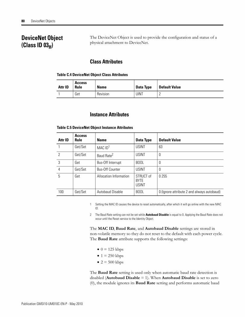
80 DeviceNet Objects
DeviceNet Object(Class ID 03H)
The DeviceNet Object is used to provide the configuration and status of a physical attachment to DeviceNet.
Class Attributes
Instance Attributes
1 Setting the MAC ID causes the device to reset automatically, after which it will go online with the new MAC ID.
2 The Baud Rate setting can not be set while Autobaud Disable is equal to 0. Applying the Baud Rate does not occur until the Reset service to the Identity Object.
The MAC ID, Baud Rate, and Autobaud Disable settings are stored in non-volatile memory so they do not reset to the default with each power cycle. The Baud Rate attribute supports the following settings:
• 0 = 125 kbps• 1 = 250 kbps• 2 = 500 kbps
The Baud Rate setting is used only when automatic baud rate detection is disabled (Autobaud Disable = 1). When Autobaud Disable is set to zero (0), the module ignores its Baud Rate setting and performs automatic baud
Table C.4 DeviceNet Object Class Attributes
Attr IDAccess Rule Name Data Type Default Value
1 Get Revision UINT 2
Table C.5 DeviceNet Object Instance Attributes
Attr IDAccess Rule Name Data Type Default Value
1 Get/Set MAC ID1 USINT 63
2 Get/Set Baud Rate2 USINT 0
3 Get Bus-Off Interrupt BOOL 0
4 Get/Set Bus-Off Counter USINT 0
5 Get Allocation Information STRUCT of BYTEUSINT
0 255
100 Get/Set Autobaud Disable BOOL 0 (Ignore attribute 2 and always autobaud)
Publication GMSI10-UM010C-EN-P - May 2010
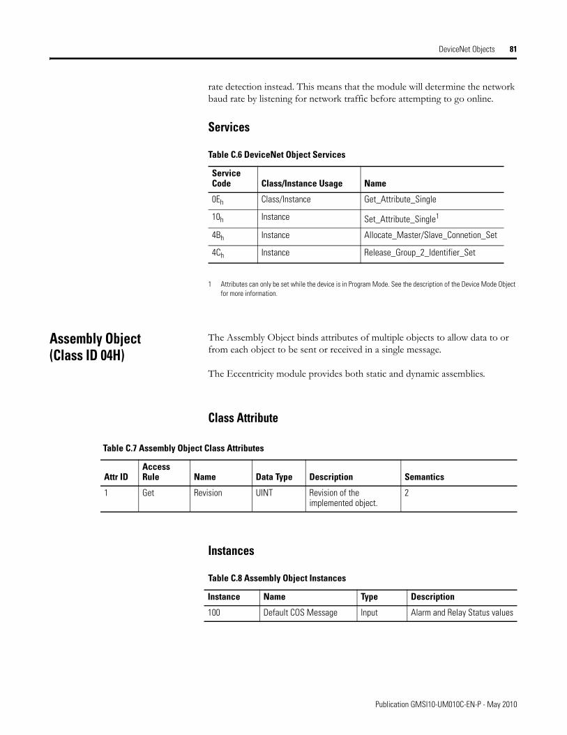
DeviceNet Objects 81
rate detection instead. This means that the module will determine the network baud rate by listening for network traffic before attempting to go online.
Services
1 Attributes can only be set while the device is in Program Mode. See the description of the Device Mode Object for more information.
Assembly Object(Class ID 04H)
The Assembly Object binds attributes of multiple objects to allow data to or from each object to be sent or received in a single message.
The Eccentricity module provides both static and dynamic assemblies.
Class Attribute
Instances
Table C.6 DeviceNet Object Services
Service Code Class/Instance Usage Name
0Eh Class/Instance Get_Attribute_Single
10h Instance Set_Attribute_Single1
4Bh Instance Allocate_Master/Slave_Connetion_Set
4Ch Instance Release_Group_2_Identifier_Set
Table C.7 Assembly Object Class Attributes
Attr IDAccess Rule Name Data Type Description Semantics
1 Get Revision UINT Revision of the implemented object.
2
Table C.8 Assembly Object Instances
Instance Name Type Description
100 Default COS Message Input Alarm and Relay Status values
Publication GMSI10-UM010C-EN-P - May 2010
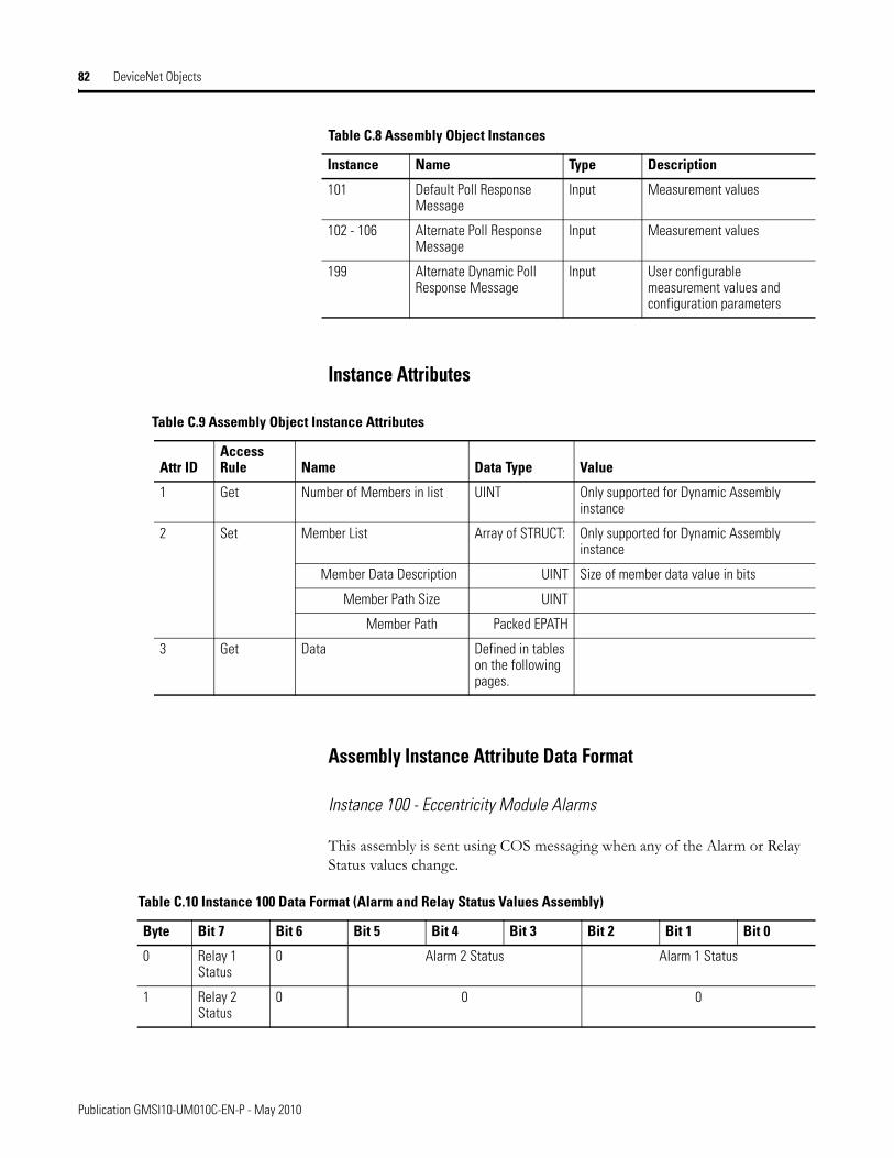
82 DeviceNet Objects
Instance Attributes
Assembly Instance Attribute Data Format
Instance 100 - Eccentricity Module Alarms
This assembly is sent using COS messaging when any of the Alarm or Relay Status values change.
101 Default Poll Response Message
Input Measurement values
102 - 106 Alternate Poll Response Message
Input Measurement values
199 Alternate Dynamic Poll Response Message
Input User configurable measurement values and configuration parameters
Table C.8 Assembly Object Instances
Instance Name Type Description
Table C.9 Assembly Object Instance Attributes
Attr IDAccess Rule Name Data Type Value
1 Get Number of Members in list UINT Only supported for Dynamic Assembly instance
2 Set Member List Array of STRUCT: Only supported for Dynamic Assembly instance
Member Data Description UINT Size of member data value in bits
Member Path Size UINT
Member Path Packed EPATH
3 Get Data Defined in tables on the following pages.
Table C.10 Instance 100 Data Format (Alarm and Relay Status Values Assembly)
Byte Bit 7 Bit 6 Bit 5 Bit 4 Bit 3 Bit 2 Bit 1 Bit 0
0 Relay 1 Status
0 Alarm 2 Status Alarm 1 Status
1 Relay 2 Status
0 0 0
Publication GMSI10-UM010C-EN-P - May 2010
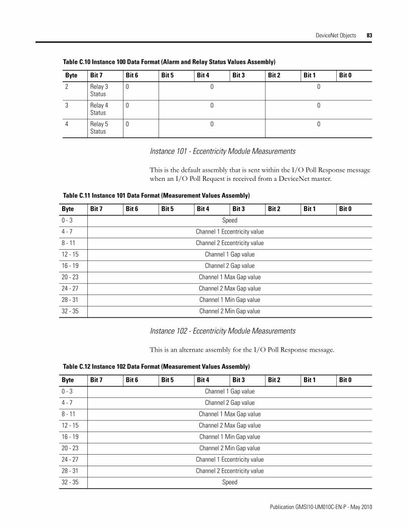
DeviceNet Objects 83
Instance 101 - Eccentricity Module Measurements
This is the default assembly that is sent within the I/O Poll Response message when an I/O Poll Request is received from a DeviceNet master.
Instance 102 - Eccentricity Module Measurements
This is an alternate assembly for the I/O Poll Response message.
2 Relay 3 Status
0 0 0
3 Relay 4 Status
0 0 0
4 Relay 5 Status
0 0 0
Table C.10 Instance 100 Data Format (Alarm and Relay Status Values Assembly)
Byte Bit 7 Bit 6 Bit 5 Bit 4 Bit 3 Bit 2 Bit 1 Bit 0
Table C.11 Instance 101 Data Format (Measurement Values Assembly)
Byte Bit 7 Bit 6 Bit 5 Bit 4 Bit 3 Bit 2 Bit 1 Bit 0
0 - 3 Speed
4 - 7 Channel 1 Eccentricity value
8 - 11 Channel 2 Eccentricity value
12 - 15 Channel 1 Gap value
16 - 19 Channel 2 Gap value
20 - 23 Channel 1 Max Gap value
24 - 27 Channel 2 Max Gap value
28 - 31 Channel 1 Min Gap value
32 - 35 Channel 2 Min Gap value
Table C.12 Instance 102 Data Format (Measurement Values Assembly)
Byte Bit 7 Bit 6 Bit 5 Bit 4 Bit 3 Bit 2 Bit 1 Bit 0
0 - 3 Channel 1 Gap value
4 - 7 Channel 2 Gap value
8 - 11 Channel 1 Max Gap value
12 - 15 Channel 2 Max Gap value
16 - 19 Channel 1 Min Gap value
20 - 23 Channel 2 Min Gap value
24 - 27 Channel 1 Eccentricity value
28 - 31 Channel 2 Eccentricity value
32 - 35 Speed
Publication GMSI10-UM010C-EN-P - May 2010
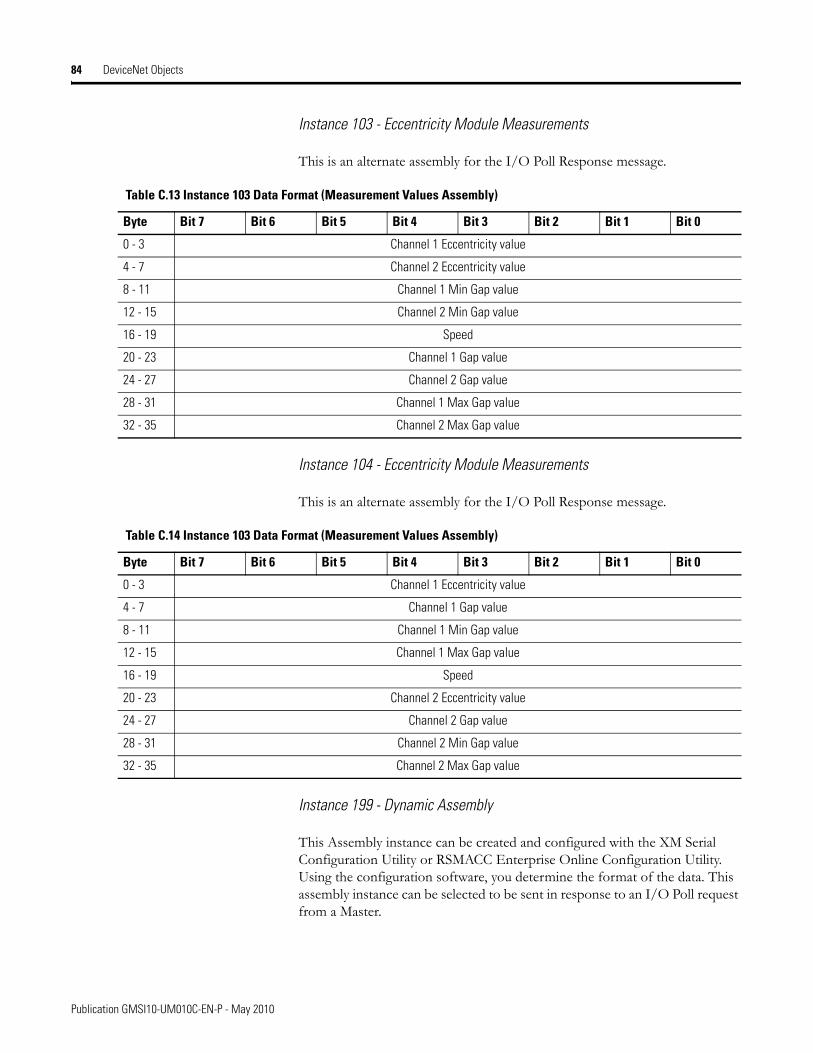
84 DeviceNet Objects
Instance 103 - Eccentricity Module Measurements
This is an alternate assembly for the I/O Poll Response message.
Instance 104 - Eccentricity Module Measurements
This is an alternate assembly for the I/O Poll Response message.
Instance 199 - Dynamic Assembly
This Assembly instance can be created and configured with the XM Serial Configuration Utility or RSMACC Enterprise Online Configuration Utility. Using the configuration software, you determine the format of the data. This assembly instance can be selected to be sent in response to an I/O Poll request from a Master.
Table C.13 Instance 103 Data Format (Measurement Values Assembly)
Byte Bit 7 Bit 6 Bit 5 Bit 4 Bit 3 Bit 2 Bit 1 Bit 0
0 - 3 Channel 1 Eccentricity value
4 - 7 Channel 2 Eccentricity value
8 - 11 Channel 1 Min Gap value
12 - 15 Channel 2 Min Gap value
16 - 19 Speed
20 - 23 Channel 1 Gap value
24 - 27 Channel 2 Gap value
28 - 31 Channel 1 Max Gap value
32 - 35 Channel 2 Max Gap value
Table C.14 Instance 103 Data Format (Measurement Values Assembly)
Byte Bit 7 Bit 6 Bit 5 Bit 4 Bit 3 Bit 2 Bit 1 Bit 0
0 - 3 Channel 1 Eccentricity value
4 - 7 Channel 1 Gap value
8 - 11 Channel 1 Min Gap value
12 - 15 Channel 1 Max Gap value
16 - 19 Speed
20 - 23 Channel 2 Eccentricity value
24 - 27 Channel 2 Gap value
28 - 31 Channel 2 Min Gap value
32 - 35 Channel 2 Max Gap value
Publication GMSI10-UM010C-EN-P - May 2010
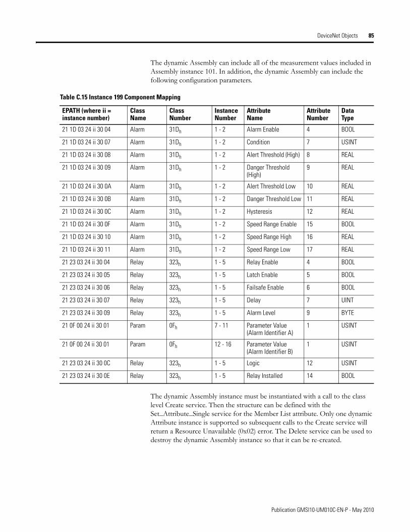
DeviceNet Objects 85
The dynamic Assembly can include all of the measurement values included in Assembly instance 101. In addition, the dynamic Assembly can include the following configuration parameters.
The dynamic Assembly instance must be instantiated with a call to the class level Create service. Then the structure can be defined with the Set_Attribute_Single service for the Member List attribute. Only one dynamic Attribute instance is supported so subsequent calls to the Create service will return a Resource Unavailable (0x02) error. The Delete service can be used to destroy the dynamic Assembly instance so that it can be re-created.
Table C.15 Instance 199 Component Mapping
EPATH (where ii = instance number)
Class Name
Class Number
Instance Number
Attribute Name
Attribute Number
DataType
21 1D 03 24 ii 30 04 Alarm 31Dh 1 - 2 Alarm Enable 4 BOOL
21 1D 03 24 ii 30 07 Alarm 31Dh 1 - 2 Condition 7 USINT
21 1D 03 24 ii 30 08 Alarm 31Dh 1 - 2 Alert Threshold (High) 8 REAL
21 1D 03 24 ii 30 09 Alarm 31Dh 1 - 2 Danger Threshold (High)
9 REAL
21 1D 03 24 ii 30 0A Alarm 31Dh 1 - 2 Alert Threshold Low 10 REAL
21 1D 03 24 ii 30 0B Alarm 31Dh 1 - 2 Danger Threshold Low 11 REAL
21 1D 03 24 ii 30 0C Alarm 31Dh 1 - 2 Hysteresis 12 REAL
21 1D 03 24 ii 30 0F Alarm 31Dh 1 - 2 Speed Range Enable 15 BOOL
21 1D 03 24 ii 30 10 Alarm 31Dh 1 - 2 Speed Range High 16 REAL
21 1D 03 24 ii 30 11 Alarm 31Dh 1 - 2 Speed Range Low 17 REAL
21 23 03 24 ii 30 04 Relay 323h 1 - 5 Relay Enable 4 BOOL
21 23 03 24 ii 30 05 Relay 323h 1 - 5 Latch Enable 5 BOOL
21 23 03 24 ii 30 06 Relay 323h 1 - 5 Failsafe Enable 6 BOOL
21 23 03 24 ii 30 07 Relay 323h 1 - 5 Delay 7 UINT
21 23 03 24 ii 30 09 Relay 323h 1 - 5 Alarm Level 9 BYTE
21 0F 00 24 ii 30 01 Param 0Fh 7 - 11 Parameter Value (Alarm Identifier A)
1 USINT
21 0F 00 24 ii 30 01 Param 0Fh 12 - 16 Parameter Value (Alarm Identifier B)
1 USINT
21 23 03 24 ii 30 0C Relay 323h 1 - 5 Logic 12 USINT
21 23 03 24 ii 30 0E Relay 323h 1 - 5 Relay Installed 14 BOOL
Publication GMSI10-UM010C-EN-P - May 2010
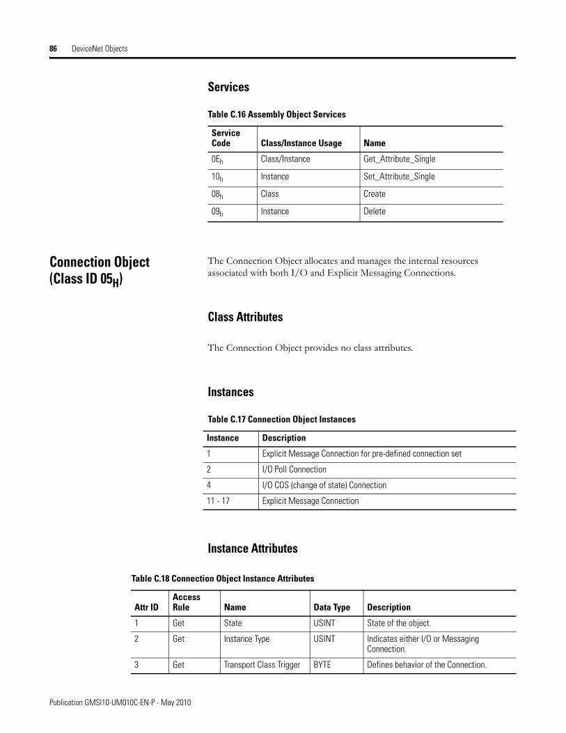
86 DeviceNet Objects
Services
Connection Object(Class ID 05H)
The Connection Object allocates and manages the internal resources associated with both I/O and Explicit Messaging Connections.
Class Attributes
The Connection Object provides no class attributes.
Instances
Instance Attributes
Table C.16 Assembly Object Services
Service Code Class/Instance Usage Name
0Eh Class/Instance Get_Attribute_Single
10h Instance Set_Attribute_Single
08h Class Create
09h Instance Delete
Table C.17 Connection Object Instances
Instance Description
1 Explicit Message Connection for pre-defined connection set
2 I/O Poll Connection
4 I/O COS (change of state) Connection
11 - 17 Explicit Message Connection
Table C.18 Connection Object Instance Attributes
Attr IDAccess Rule Name Data Type Description
1 Get State USINT State of the object.
2 Get Instance Type USINT Indicates either I/O or Messaging Connection.
3 Get Transport Class Trigger BYTE Defines behavior of the Connection.
Publication GMSI10-UM010C-EN-P - May 2010
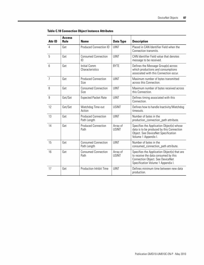
DeviceNet Objects 87
4 Get Produced Connection ID UINT Placed in CAN Identifier Field when the Connection transmits.
5 Get Consumed Connection ID
UINT CAN Identifier Field value that denotes message to be received.
6 Get Initial Comm Characteristics
BYTE Defines the Message Group(s) across which productions and consumptions associated with this Connection occur.
7 Get Produced Connection Size
UINT Maximum number of bytes transmitted across this Connection.
8 Get Consumed Connection Size
UINT Maximum number of bytes received across this Connection.
9 Get/Set Expected Packet Rate UINT Defines timing associated with this Connection.
12 Get/Set Watchdog Time-out Action
USINT Defines how to handle Inactivity/Watchdog timeouts.
13 Get Produced Connection Path Length
UINT Number of bytes in the production_connection_path attribute.
14 Get Produced Connection Path
Array of USINT
Specifies the Application Object(s) whose data is to be produced by this Connection Object. See DeviceNet Specification Volume 1 Appendix I.
15 Get Consumed Connection Path Length
UINT Number of bytes in the consumed_connection_path attribute.
16 Get Consumed Connection Path
Array of USINT
Specifies the Application Object(s) that are to receive the data consumed by this Connection Object. See DeviceNet Specification Volume 1 Appendix I.
17 Get Production Inhibit Time UINT Defines minimum time between new data production.
Table C.18 Connection Object Instance Attributes
Attr IDAccess Rule Name Data Type Description
Publication GMSI10-UM010C-EN-P - May 2010
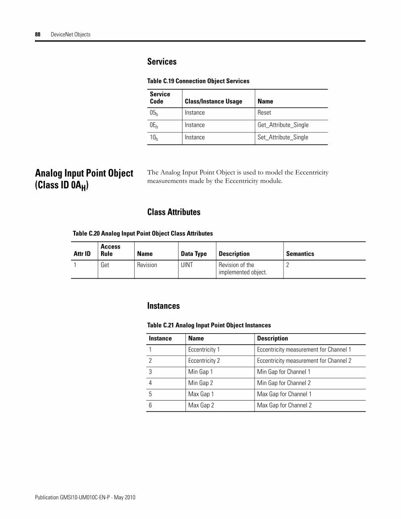
88 DeviceNet Objects
Services
Analog Input Point Object(Class ID 0AH)
The Analog Input Point Object is used to model the Eccentricity measurements made by the Eccentricity module.
Class Attributes
Instances
Table C.19 Connection Object Services
Service Code Class/Instance Usage Name
05h Instance Reset
0Eh Instance Get_Attribute_Single
10h Instance Set_Attribute_Single
Table C.20 Analog Input Point Object Class Attributes
Attr IDAccess Rule Name Data Type Description Semantics
1 Get Revision UINT Revision of the implemented object.
2
Table C.21 Analog Input Point Object Instances
Instance Name Description
1 Eccentricity 1 Eccentricity measurement for Channel 1
2 Eccentricity 2 Eccentricity measurement for Channel 2
3 Min Gap 1 Min Gap for Channel 1
4 Min Gap 2 Min Gap for Channel 2
5 Max Gap 1 Max Gap for Channel 1
6 Max Gap 2 Max Gap for Channel 2
Publication GMSI10-UM010C-EN-P - May 2010
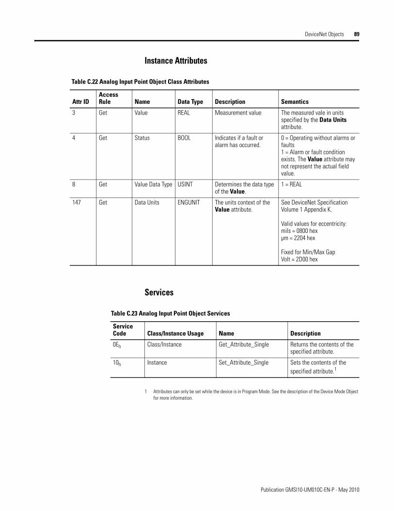
DeviceNet Objects 89
Instance Attributes
Services
1 Attributes can only be set while the device is in Program Mode. See the description of the Device Mode Object for more information.
Table C.22 Analog Input Point Object Class Attributes
Attr IDAccess Rule Name Data Type Description Semantics
3 Get Value REAL Measurement value The measured vale in units specified by the Data Units attribute.
4 Get Status BOOL Indicates if a fault or alarm has occurred.
0 = Operating without alarms or faults1 = Alarm or fault condition exists. The Value attribute may not represent the actual field value.
8 Get Value Data Type USINT Determines the data type of the Value.
1 = REAL
147 Get Data Units ENGUNIT The units context of the Value attribute.
See DeviceNet Specification Volume 1 Appendix K.
Valid values for eccentricity:mils = 0800 hexµm = 2204 hex
Fixed for Min/Max GapVolt = 2D00 hex
Table C.23 Analog Input Point Object Services
Service Code Class/Instance Usage Name Description
0Eh Class/Instance Get_Attribute_Single Returns the contents of the specified attribute.
10h Instance Set_Attribute_Single Sets the contents of the specified attribute.1
Publication GMSI10-UM010C-EN-P - May 2010
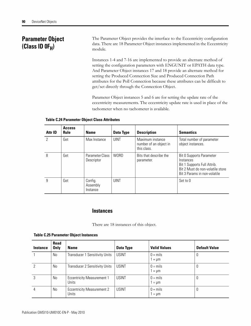
90 DeviceNet Objects
Parameter Object(Class ID 0FH)
The Parameter Object provides the interface to the Eccentricity configuration data. There are 18 Parameter Object instances implemented in the Eccentricity module.
Instances 1-4 and 7-16 are implemented to provide an alternate method of setting the configuration parameters with ENGUNIT or EPATH data type. And Parameter Object instances 17 and 18 provide an alternate method for setting the Produced Connection Size and Produced Connection Path attributes for the Poll Connection because these attributes can be difficult to get/set directly through the Connection Object.
Parameter Object instances 5 and 6 are for setting the update rate of the eccentricity measurements. The eccentricity update rate is used in place of the tachometer when no tachometer is available.
Instances
There are 18 instances of this object.
Table C.24 Parameter Object Class Attributes
Attr IDAccess Rule Name Data Type Description Semantics
2 Get Max Instance UINT Maximum instance number of an object in this class.
Total number of parameter object instances.
8 Get Parameter Class Descriptor
WORD Bits that describe the parameter.
Bit 0 Supports Parameter InstancesBit 1 Supports Full Attrib.Bit 2 Must do non-volatile storeBit 3 Params in non-volatile
9 Get Config. Assembly Instance
UINT Set to 0
Table C.25 Parameter Object Instances
Instance Read Only Name Data Type Valid Values Default Value
1 No Transducer 1 Sensitivity Units USINT 0 = mils1 = µm
0
2 No Transducer 2 Sensitivity Units USINT 0 = mils1 = µm
0
3 No Eccentricity Measurement 1 Units
USINT 0 = mils1 = µm
0
4 No Eccentricity Measurement 2 Units
USINT 0 = mils1 = µm
0
Publication GMSI10-UM010C-EN-P - May 2010
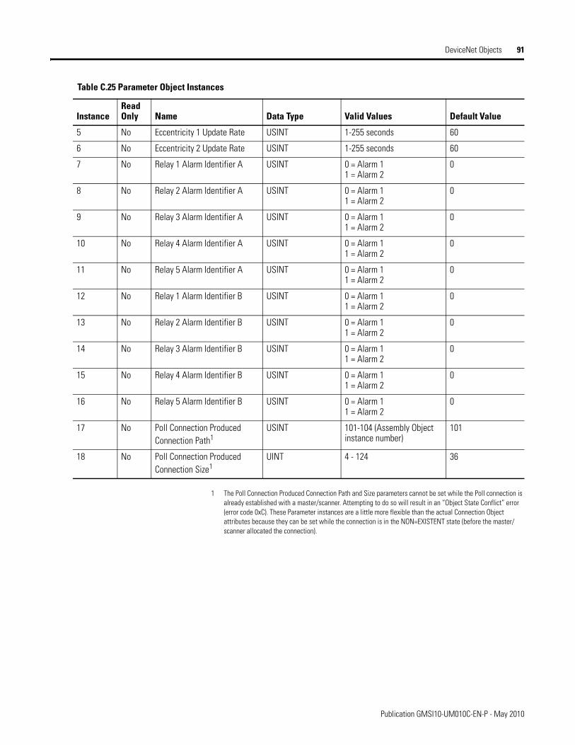
DeviceNet Objects 91
1 The Poll Connection Produced Connection Path and Size parameters cannot be set while the Poll connection is already established with a master/scanner. Attempting to do so will result in an “Object State Conflict” error (error code 0xC). These Parameter instances are a little more flexible than the actual Connection Object attributes because they can be set while the connection is in the NON=EXISTENT state (before the master/scanner allocated the connection).
5 No Eccentricity 1 Update Rate USINT 1-255 seconds 60
6 No Eccentricity 2 Update Rate USINT 1-255 seconds 60
7 No Relay 1 Alarm Identifier A USINT 0 = Alarm 11 = Alarm 2
0
8 No Relay 2 Alarm Identifier A USINT 0 = Alarm 11 = Alarm 2
0
9 No Relay 3 Alarm Identifier A USINT 0 = Alarm 11 = Alarm 2
0
10 No Relay 4 Alarm Identifier A USINT 0 = Alarm 11 = Alarm 2
0
11 No Relay 5 Alarm Identifier A USINT 0 = Alarm 11 = Alarm 2
0
12 No Relay 1 Alarm Identifier B USINT 0 = Alarm 11 = Alarm 2
0
13 No Relay 2 Alarm Identifier B USINT 0 = Alarm 11 = Alarm 2
0
14 No Relay 3 Alarm Identifier B USINT 0 = Alarm 11 = Alarm 2
0
15 No Relay 4 Alarm Identifier B USINT 0 = Alarm 11 = Alarm 2
0
16 No Relay 5 Alarm Identifier B USINT 0 = Alarm 11 = Alarm 2
0
17 No Poll Connection Produced Connection Path1
USINT 101-104 (Assembly Object instance number)
101
18 No Poll Connection Produced Connection Size1
UINT 4 - 124 36
Table C.25 Parameter Object Instances
Instance Read Only Name Data Type Valid Values Default Value
Publication GMSI10-UM010C-EN-P - May 2010
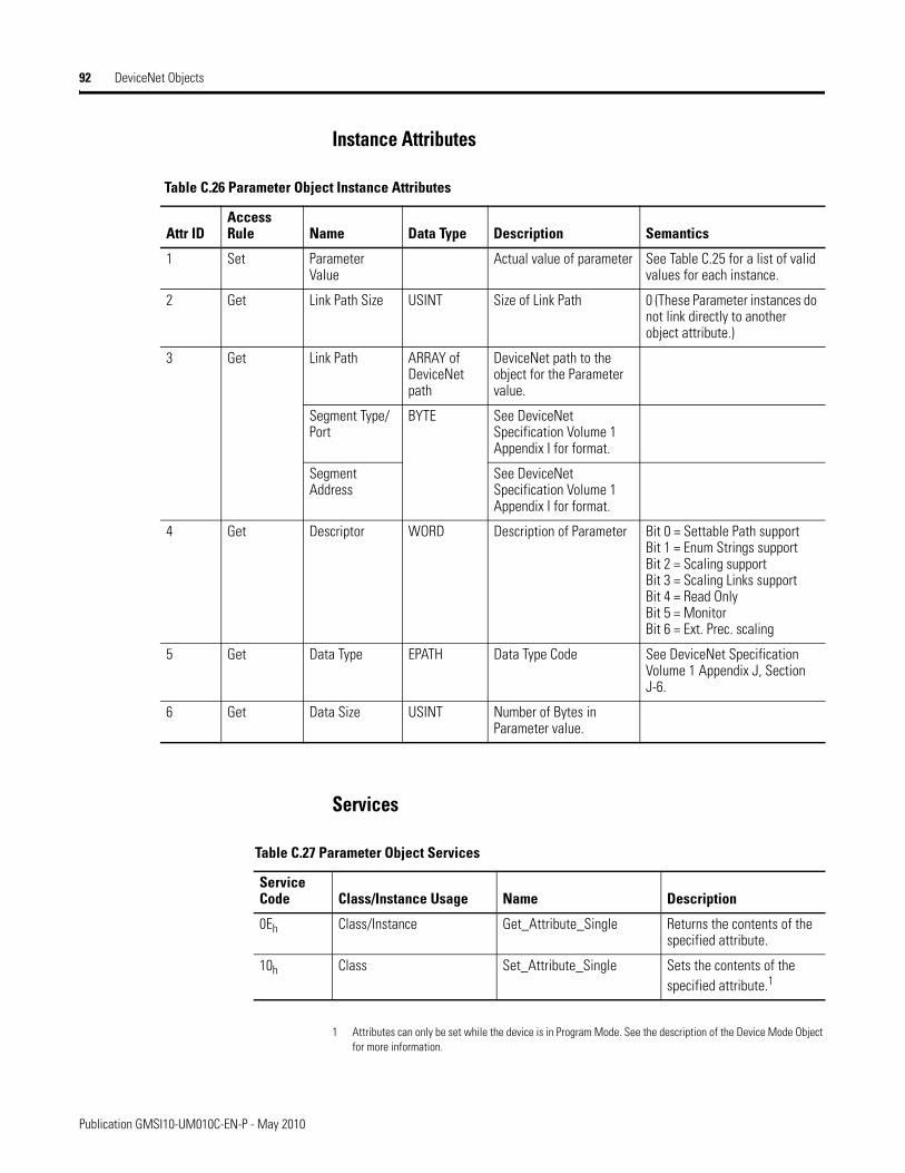
92 DeviceNet Objects
Instance Attributes
Services
1 Attributes can only be set while the device is in Program Mode. See the description of the Device Mode Object for more information.
Table C.26 Parameter Object Instance Attributes
Attr IDAccess Rule Name Data Type Description Semantics
1 Set Parameter Value
Actual value of parameter See Table C.25 for a list of valid values for each instance.
2 Get Link Path Size USINT Size of Link Path 0 (These Parameter instances do not link directly to another object attribute.)
3
Get
Link Path ARRAY of DeviceNet path
DeviceNet path to the object for the Parameter value.
Segment Type/Port
BYTE See DeviceNet Specification Volume 1 Appendix I for format.
Segment Address
See DeviceNet Specification Volume 1 Appendix I for format.
4 Get Descriptor WORD Description of Parameter Bit 0 = Settable Path supportBit 1 = Enum Strings supportBit 2 = Scaling supportBit 3 = Scaling Links supportBit 4 = Read OnlyBit 5 = MonitorBit 6 = Ext. Prec. scaling
5 Get Data Type EPATH Data Type Code See DeviceNet Specification Volume 1 Appendix J, Section J-6.
6 Get Data Size USINT Number of Bytes in Parameter value.
Table C.27 Parameter Object Services
Service Code Class/Instance Usage Name Description
0Eh Class/Instance Get_Attribute_Single Returns the contents of the specified attribute.
10h Class Set_Attribute_Single Sets the contents of the specified attribute.1
Publication GMSI10-UM010C-EN-P - May 2010
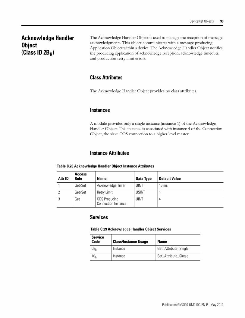
DeviceNet Objects 93
Acknowledge Handler Object(Class ID 2BH)
The Acknowledge Handler Object is used to manage the reception of message acknowledgments. This object communicates with a message producing Application Object within a device. The Acknowledge Handler Object notifies the producing application of acknowledge reception, acknowledge timeouts, and production retry limit errors.
Class Attributes
The Acknowledge Handler Object provides no class attributes.
Instances
A module provides only a single instance (instance 1) of the Acknowledge Handler Object. This instance is associated with instance 4 of the Connection Object, the slave COS connection to a higher level master.
Instance Attributes
Services
Table C.28 Acknowledge Handler Object Instance Attributes
Attr IDAccess Rule Name Data Type Default Value
1 Get/Set Acknowledge Timer UINT 16 ms
2 Get/Set Retry Limit USINT 1
3 Get COS Producing Connection Instance
UINT 4
Table C.29 Acknowledge Handler Object Services
Service Code Class/Instance Usage Name
0Eh Instance Get_Attribute_Single
10h Instance Set_Attribute_Single
Publication GMSI10-UM010C-EN-P - May 2010
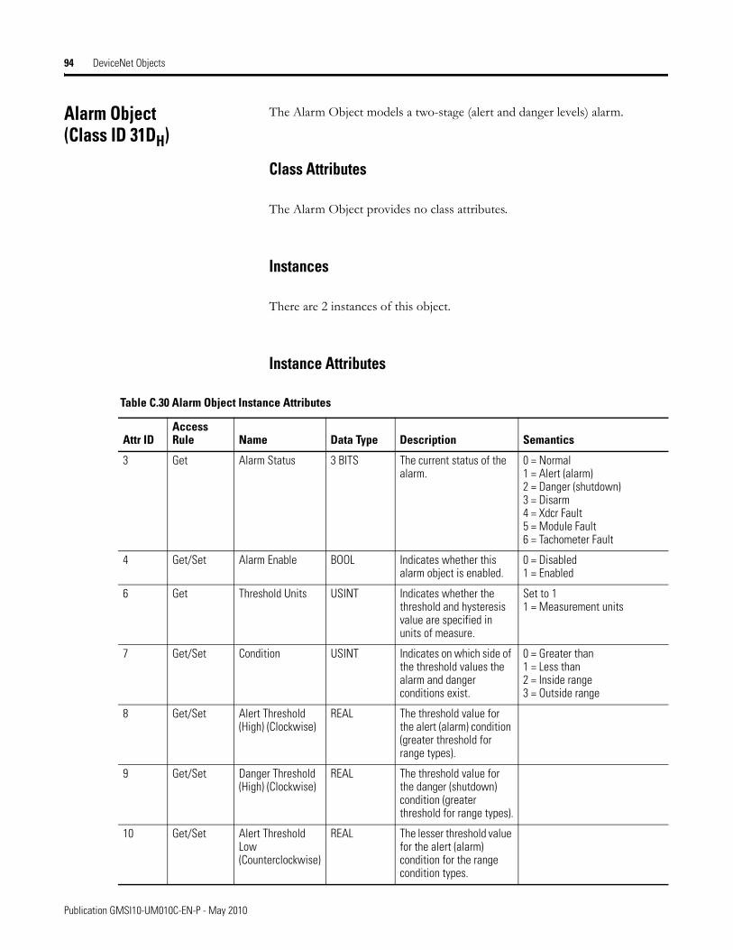
94 DeviceNet Objects
Alarm Object(Class ID 31DH)
The Alarm Object models a two-stage (alert and danger levels) alarm.
Class Attributes
The Alarm Object provides no class attributes.
Instances
There are 2 instances of this object.
Instance Attributes
Table C.30 Alarm Object Instance Attributes
Attr IDAccess Rule Name Data Type Description Semantics
3 Get Alarm Status 3 BITS The current status of the alarm.
0 = Normal1 = Alert (alarm)2 = Danger (shutdown)3 = Disarm4 = Xdcr Fault5 = Module Fault6 = Tachometer Fault
4 Get/Set Alarm Enable BOOL Indicates whether this alarm object is enabled.
0 = Disabled1 = Enabled
6 Get Threshold Units USINT Indicates whether the threshold and hysteresis value are specified in units of measure.
Set to 11 = Measurement units
7 Get/Set Condition USINT Indicates on which side of the threshold values the alarm and danger conditions exist.
0 = Greater than1 = Less than2 = Inside range3 = Outside range
8 Get/Set Alert Threshold (High) (Clockwise)
REAL The threshold value for the alert (alarm) condition (greater threshold for range types).
9 Get/Set Danger Threshold (High) (Clockwise)
REAL The threshold value for the danger (shutdown) condition (greater threshold for range types).
10 Get/Set Alert Threshold Low (Counterclockwise)
REAL The lesser threshold value for the alert (alarm) condition for the range condition types.
Publication GMSI10-UM010C-EN-P - May 2010
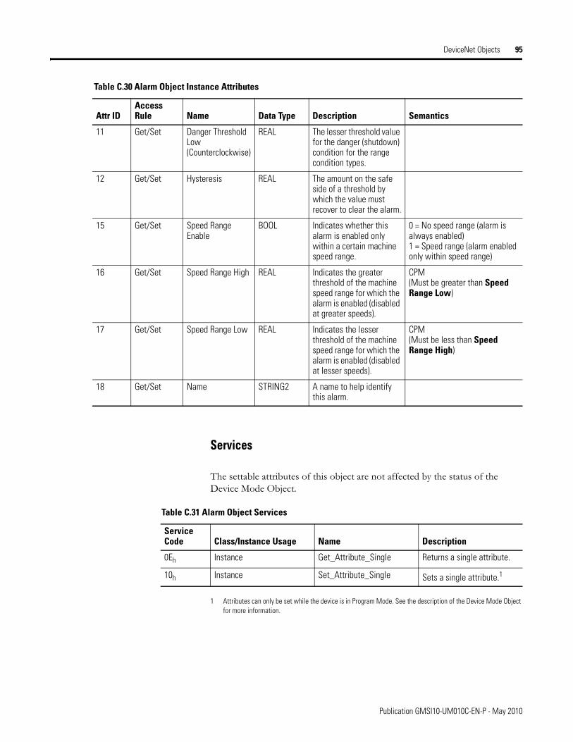
DeviceNet Objects 95
Services
The settable attributes of this object are not affected by the status of the Device Mode Object.
1 Attributes can only be set while the device is in Program Mode. See the description of the Device Mode Object for more information.
11 Get/Set Danger Threshold Low (Counterclockwise)
REAL The lesser threshold value for the danger (shutdown) condition for the range condition types.
12 Get/Set Hysteresis REAL The amount on the safe side of a threshold by which the value must recover to clear the alarm.
15 Get/Set Speed Range Enable
BOOL Indicates whether this alarm is enabled only within a certain machine speed range.
0 = No speed range (alarm is always enabled)1 = Speed range (alarm enabled only within speed range)
16 Get/Set Speed Range High REAL Indicates the greater threshold of the machine speed range for which the alarm is enabled (disabled at greater speeds).
CPM(Must be greater than Speed Range Low)
17 Get/Set Speed Range Low REAL Indicates the lesser threshold of the machine speed range for which the alarm is enabled (disabled at lesser speeds).
CPM(Must be less than Speed Range High)
18 Get/Set Name STRING2 A name to help identify this alarm.
Table C.30 Alarm Object Instance Attributes
Attr IDAccess Rule Name Data Type Description Semantics
Table C.31 Alarm Object Services
Service Code Class/Instance Usage Name Description
0Eh Instance Get_Attribute_Single Returns a single attribute.
10h Instance Set_Attribute_Single Sets a single attribute.1
Publication GMSI10-UM010C-EN-P - May 2010
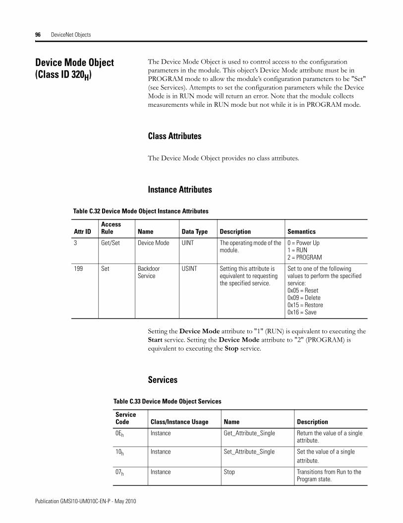
96 DeviceNet Objects
Device Mode Object(Class ID 320H)
The Device Mode Object is used to control access to the configuration parameters in the module. This object’s Device Mode attribute must be in PROGRAM mode to allow the module’s configuration parameters to be "Set" (see Services). Attempts to set the configuration parameters while the Device Mode is in RUN mode will return an error. Note that the module collects measurements while in RUN mode but not while it is in PROGRAM mode.
Class Attributes
The Device Mode Object provides no class attributes.
Instance Attributes
Setting the Device Mode attribute to "1" (RUN) is equivalent to executing the Start service. Setting the Device Mode attribute to "2" (PROGRAM) is equivalent to executing the Stop service.
Services
Table C.32 Device Mode Object Instance Attributes
Attr IDAccess Rule Name Data Type Description Semantics
3 Get/Set Device Mode UINT The operating mode of the module.
0 = Power Up1 = RUN2 = PROGRAM
199 Set Backdoor Service
USINT Setting this attribute is equivalent to requesting the specified service.
Set to one of the following values to perform the specified service:0x05 = Reset0x09 = Delete0x15 = Restore0x16 = Save
Table C.33 Device Mode Object Services
Service Code Class/Instance Usage Name Description
0Eh Instance Get_Attribute_Single Return the value of a single attribute.
10h Instance Set_Attribute_Single Set the value of a single attribute.
07h Instance Stop Transitions from Run to the Program state.
Publication GMSI10-UM010C-EN-P - May 2010
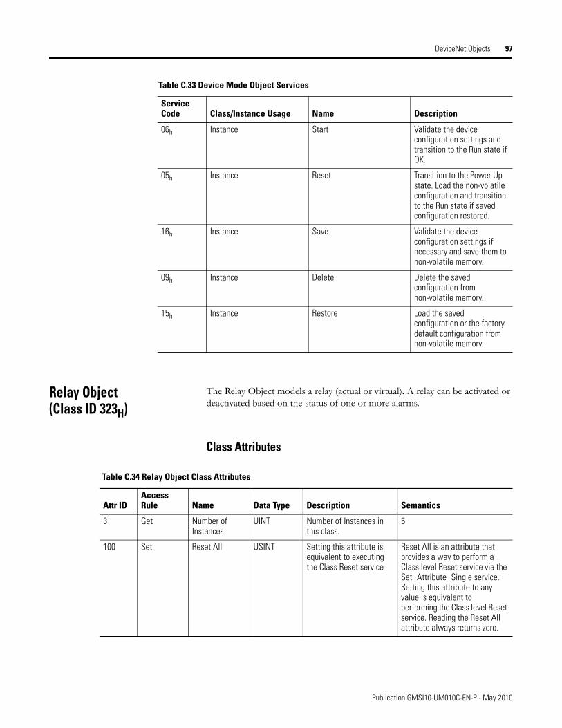
DeviceNet Objects 97
Relay Object(Class ID 323H)
The Relay Object models a relay (actual or virtual). A relay can be activated or deactivated based on the status of one or more alarms.
Class Attributes
06h Instance Start Validate the device configuration settings and transition to the Run state if OK.
05h Instance Reset Transition to the Power Up state. Load the non-volatile configuration and transition to the Run state if saved configuration restored.
16h Instance Save Validate the device configuration settings if necessary and save them to non-volatile memory.
09h Instance Delete Delete the saved configuration from non-volatile memory.
15h Instance Restore Load the saved configuration or the factory default configuration from non-volatile memory.
Table C.33 Device Mode Object Services
Service Code Class/Instance Usage Name Description
Table C.34 Relay Object Class Attributes
Attr IDAccess Rule Name Data Type Description Semantics
3 Get Number of Instances
UINT Number of Instances in this class.
5
100 Set Reset All USINT Setting this attribute is equivalent to executing the Class Reset service
Reset All is an attribute that provides a way to perform a Class level Reset service via the Set_Attribute_Single service. Setting this attribute to any value is equivalent to performing the Class level Reset service. Reading the Reset All attribute always returns zero.
Publication GMSI10-UM010C-EN-P - May 2010
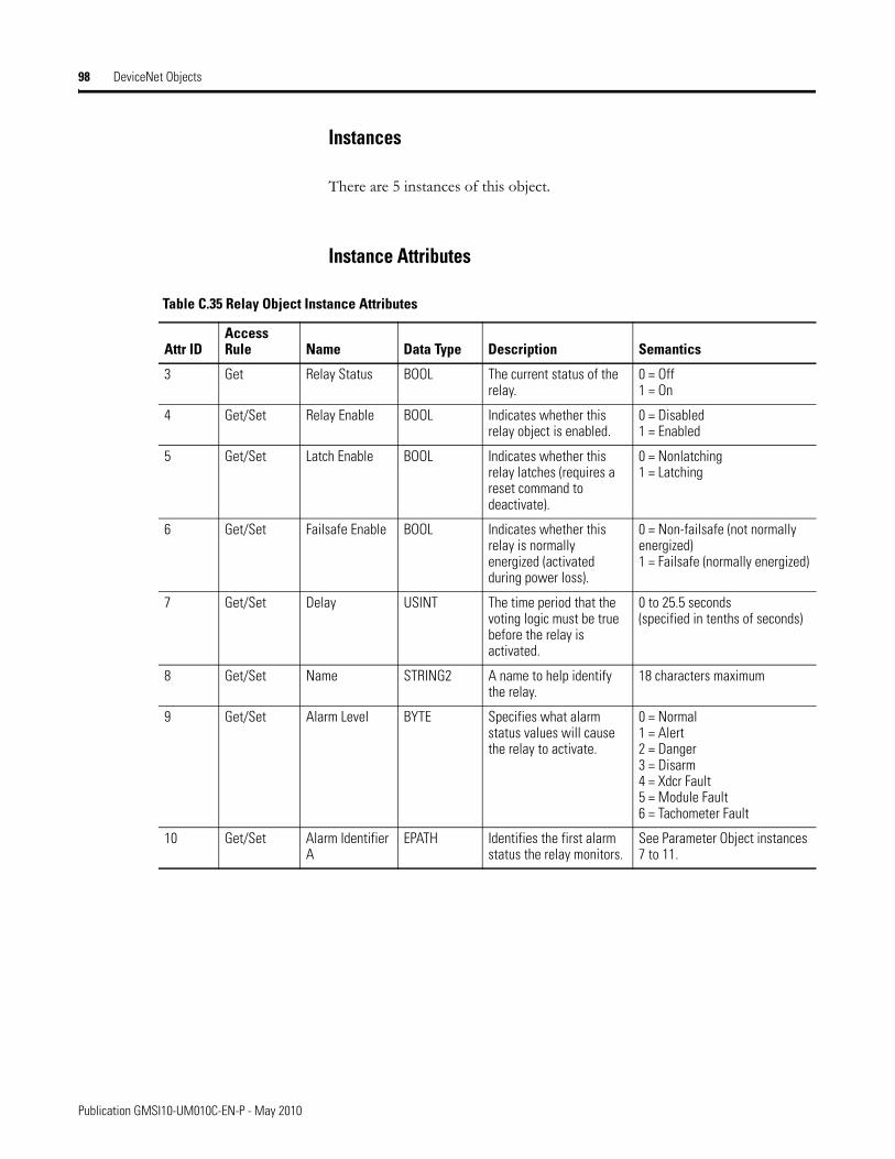
98 DeviceNet Objects
Instances
There are 5 instances of this object.
Instance Attributes
Table C.35 Relay Object Instance Attributes
Attr IDAccess Rule Name Data Type Description Semantics
3 Get Relay Status BOOL The current status of the relay.
0 = Off1 = On
4 Get/Set Relay Enable BOOL Indicates whether this relay object is enabled.
0 = Disabled1 = Enabled
5 Get/Set Latch Enable BOOL Indicates whether this relay latches (requires a reset command to deactivate).
0 = Nonlatching1 = Latching
6 Get/Set Failsafe Enable BOOL Indicates whether this relay is normally energized (activated during power loss).
0 = Non-failsafe (not normally energized)1 = Failsafe (normally energized)
7 Get/Set Delay USINT The time period that the voting logic must be true before the relay is activated.
0 to 25.5 seconds(specified in tenths of seconds)
8 Get/Set Name STRING2 A name to help identify the relay.
18 characters maximum
9 Get/Set Alarm Level BYTE Specifies what alarm status values will cause the relay to activate.
0 = Normal1 = Alert2 = Danger3 = Disarm4 = Xdcr Fault5 = Module Fault6 = Tachometer Fault
10 Get/Set Alarm Identifier A
EPATH Identifies the first alarm status the relay monitors.
See Parameter Object instances 7 to 11.
Publication GMSI10-UM010C-EN-P - May 2010
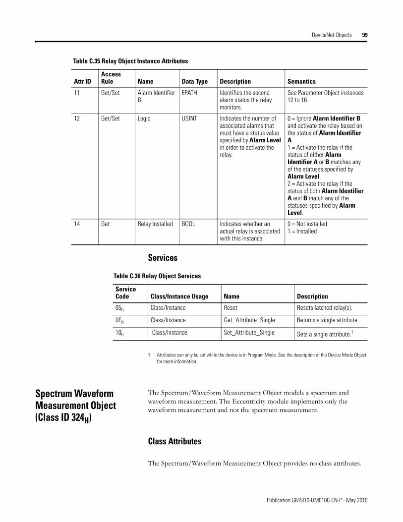
DeviceNet Objects 99
Services
1 Attributes can only be set while the device is in Program Mode. See the description of the Device Mode Object for more information.
Spectrum Waveform Measurement Object(Class ID 324H)
The Spectrum/Waveform Measurement Object models a spectrum and waveform measurement. The Eccentricity module implements only the waveform measurement and not the spectrum measurement.
Class Attributes
The Spectrum/Waveform Measurement Object provides no class attributes.
11 Get/Set Alarm Identifier B
EPATH Identifies the second alarm status the relay monitors.
See Parameter Object instances 12 to 16.
12 Get/Set Logic USINT Indicates the number of associated alarms that must have a status value specified by Alarm Level in order to activate the relay.
0 = Ignore Alarm Identifier B and activate the relay based on the status of Alarm Identifier A.1 = Activate the relay if the status of either Alarm Identifier A or B matches any of the statuses specified by Alarm Level.2 = Activate the relay if the status of both Alarm Identifier A and B match any of the statuses specified by Alarm Level.
14 Get Relay Installed BOOL Indicates whether an actual relay is associated with this instance.
0 = Not installed1 = Installed
Table C.35 Relay Object Instance Attributes
Attr IDAccess Rule Name Data Type Description Semantics
Table C.36 Relay Object Services
Service Code Class/Instance Usage Name Description
05h Class/Instance Reset Resets latched relay(s).
0Eh Class/Instance Get_Attribute_Single Returns a single attribute.
10h Class/Instance Set_Attribute_Single Sets a single attribute.1
Publication GMSI10-UM010C-EN-P - May 2010
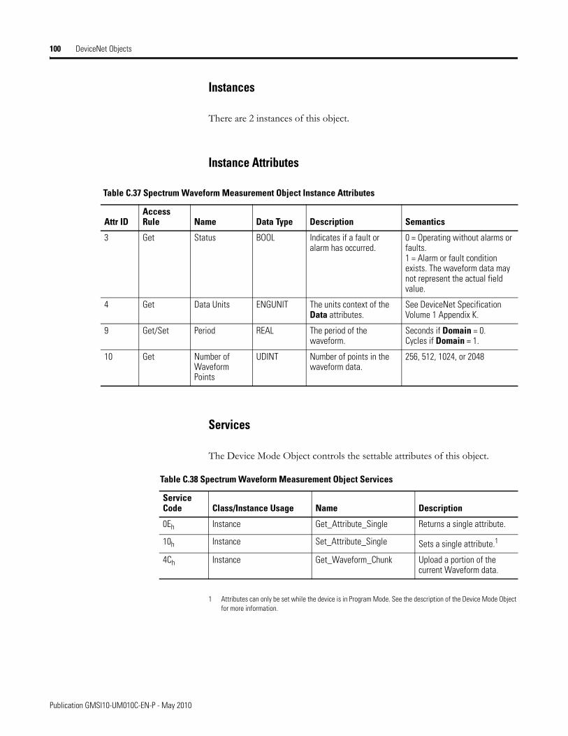
100 DeviceNet Objects
Instances
There are 2 instances of this object.
Instance Attributes
Services
The Device Mode Object controls the settable attributes of this object.
1 Attributes can only be set while the device is in Program Mode. See the description of the Device Mode Object for more information.
Table C.37 Spectrum Waveform Measurement Object Instance Attributes
Attr IDAccess Rule Name Data Type Description Semantics
3 Get Status BOOL Indicates if a fault or alarm has occurred.
0 = Operating without alarms or faults.1 = Alarm or fault condition exists. The waveform data may not represent the actual field value.
4 Get Data Units ENGUNIT The units context of the Data attributes.
See DeviceNet Specification Volume 1 Appendix K.
9 Get/Set Period REAL The period of the waveform.
Seconds if Domain = 0.Cycles if Domain = 1.
10 Get Number of Waveform Points
UDINT Number of points in the waveform data.
256, 512, 1024, or 2048
Table C.38 Spectrum Waveform Measurement Object Services
Service Code Class/Instance Usage Name Description
0Eh Instance Get_Attribute_Single Returns a single attribute.
10h Instance Set_Attribute_Single Sets a single attribute.1
4Ch Instance Get_Waveform_Chunk Upload a portion of the current Waveform data.
Publication GMSI10-UM010C-EN-P - May 2010

DeviceNet Objects 101
Get_Waveform_Chunk
This service returns a portion of the respective data structure. It is likely that the waveform data structure will be too large to transfer over the network in one message. This service allows the data structures to be transferred over the network in smaller portions so that the explicit message buffer does not need to be so large.
The Waveform Data structure contains an array of values that, taken together, are the output of the sampling performed by the Spectrum/Waveform Measurement Object on the input signal. The Waveform Data array values are normalized and must be converted to floating point to obtain the true values.
The total size of the Waveform Data structure in DWORD is: 3 + (Number of Waveform Points / 2)
The Waveform Data is an array of INT (16-bit signed integers ranging from -32768 to 32767). The number of INTs in the Waveform Data array is equal to the Number of Waveform Points. To convert the normalized Waveform Data into floating point values, use the following equations:
Where Float Datan is the value for the nth waveform point, and 0 ≤ n ≤ Number of Waveform Points.
Table C.39 Waveform Data Structure
Byte (DWORD) offset within structure Structure Member Data Type Description
0 (0) Number of Waveform Points
UDINT Number of points in the waveform data. This should be equal to the Number of Waveform Points attribute setting. It is provided within this structure to assist in determining the size of the structure.
4 (1) Period REAL The period of the waveform.This is the actual period of the waveform and may vary from the Period attribute setting.
8 (2) Amplitude Reference
REAL Normalization factorThis factor is used to convert the normalized array data into floating point values.
12 (3) Normalized Value Array
Array of INT The normalized waveform data pointsThese must be converted to floating point values using the Amplitude Reference value.
Float Datan Amplitude Reference Normalized Datan
32768-----------------------------------------------=
Publication GMSI10-UM010C-EN-P - May 2010
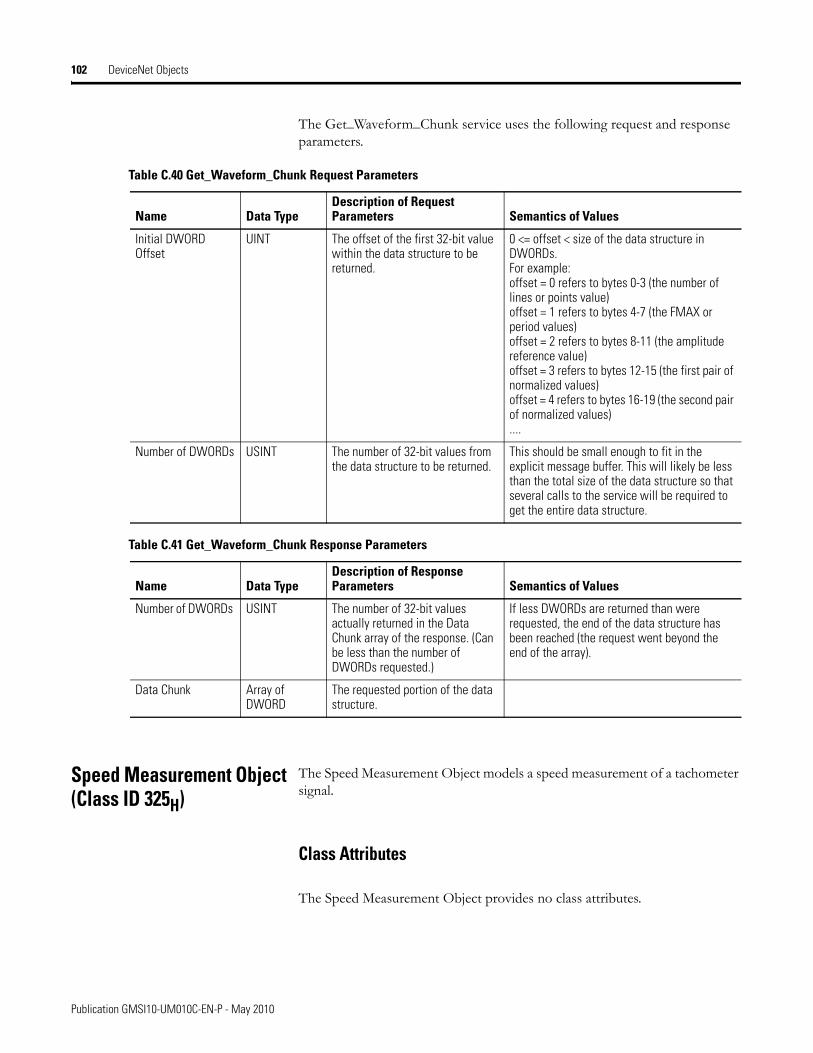
102 DeviceNet Objects
The Get_Waveform_Chunk service uses the following request and response parameters.
Speed Measurement Object(Class ID 325H)
The Speed Measurement Object models a speed measurement of a tachometer signal.
Class Attributes
The Speed Measurement Object provides no class attributes.
Table C.40 Get_Waveform_Chunk Request Parameters
Name Data TypeDescription of Request Parameters Semantics of Values
Initial DWORD Offset
UINT The offset of the first 32-bit value within the data structure to be returned.
0 <= offset < size of the data structure in DWORDs.For example:offset = 0 refers to bytes 0-3 (the number of lines or points value)offset = 1 refers to bytes 4-7 (the FMAX or period values)offset = 2 refers to bytes 8-11 (the amplitude reference value)offset = 3 refers to bytes 12-15 (the first pair of normalized values)offset = 4 refers to bytes 16-19 (the second pair of normalized values)....
Number of DWORDs USINT The number of 32-bit values from the data structure to be returned.
This should be small enough to fit in the explicit message buffer. This will likely be less than the total size of the data structure so that several calls to the service will be required to get the entire data structure.
Table C.41 Get_Waveform_Chunk Response Parameters
Name Data TypeDescription of Response Parameters Semantics of Values
Number of DWORDs USINT The number of 32-bit values actually returned in the Data Chunk array of the response. (Can be less than the number of DWORDs requested.)
If less DWORDs are returned than were requested, the end of the data structure has been reached (the request went beyond the end of the array).
Data Chunk Array of DWORD
The requested portion of the data structure.
Publication GMSI10-UM010C-EN-P - May 2010
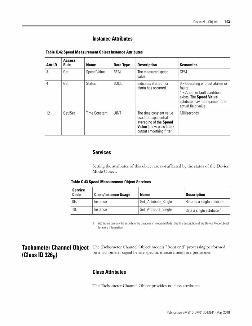
DeviceNet Objects 103
Instance Attributes
Services
Setting the attributes of this object are not affected by the status of the Device Mode Object.
1 Attributes can only be set while the device is in Program Mode. See the description of the Device Mode Object for more information.
Tachometer Channel Object(Class ID 326H)
The Tachometer Channel Object models "front end" processing performed on a tachometer signal before specific measurements are performed.
Class Attributes
The Tachometer Channel Object provides no class attributes.
Table C.42 Speed Measurement Object Instance Attributes
Attr IDAccess Rule Name Data Type Description Semantics
3 Get Speed Value REAL The measured speed value.
CPM
4 Get Status BOOL Indicates if a fault or alarm has occurred.
0 = Operating without alarms or faults1 = Alarm or fault condition exists. The Speed Value attribute may not represent the actual field value.
12 Get/Set Time Constant UINT The time constant value used for exponential averaging of the Speed Value (a low pass filter/output smoothing filter).
Milliseconds
Table C.43 Speed Measurement Object Services
Service Code Class/Instance Usage Name Description
0Eh Instance Get_Attribute_Single Returns a single attribute.
10h Instance Set_Attribute_Single Sets a single attribute.1
Publication GMSI10-UM010C-EN-P - May 2010
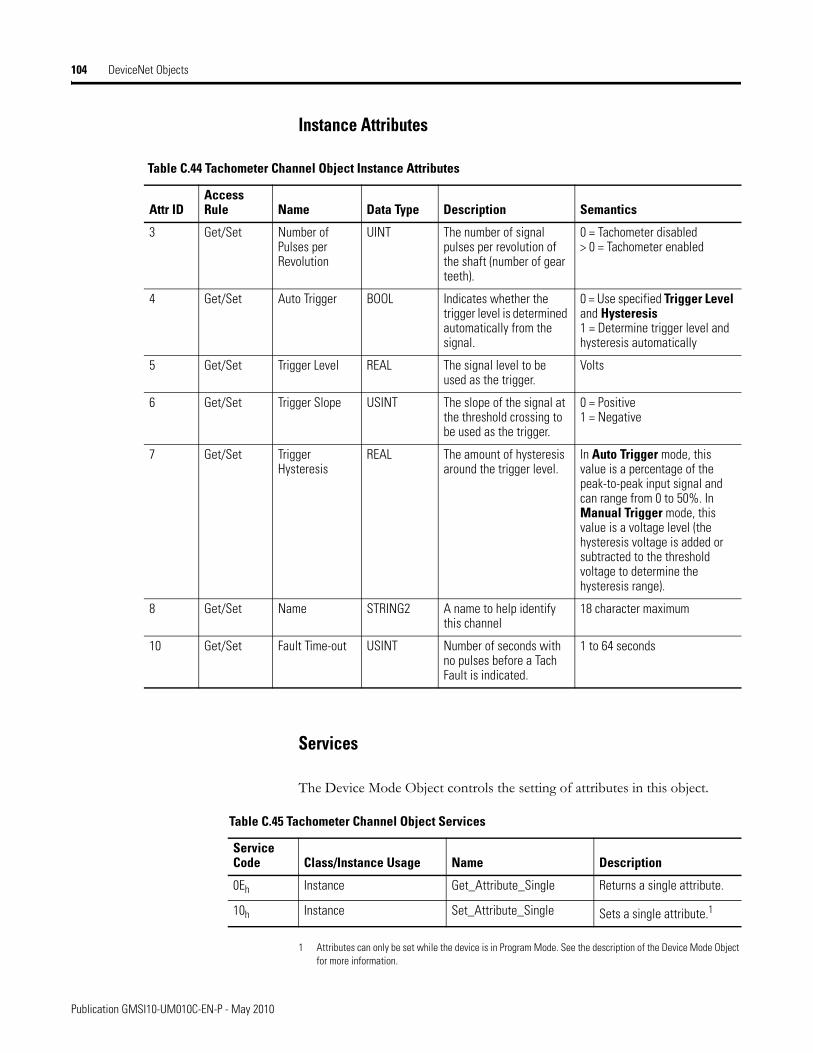
104 DeviceNet Objects
Instance Attributes
Services
The Device Mode Object controls the setting of attributes in this object.
1 Attributes can only be set while the device is in Program Mode. See the description of the Device Mode Object for more information.
Table C.44 Tachometer Channel Object Instance Attributes
Attr IDAccess Rule Name Data Type Description Semantics
3 Get/Set Number of Pulses per Revolution
UINT The number of signal pulses per revolution of the shaft (number of gear teeth).
0 = Tachometer disabled> 0 = Tachometer enabled
4 Get/Set Auto Trigger BOOL Indicates whether the trigger level is determined automatically from the signal.
0 = Use specified Trigger Level and Hysteresis1 = Determine trigger level and hysteresis automatically
5 Get/Set Trigger Level REAL The signal level to be used as the trigger.
Volts
6 Get/Set Trigger Slope USINT The slope of the signal at the threshold crossing to be used as the trigger.
0 = Positive1 = Negative
7 Get/Set Trigger Hysteresis
REAL The amount of hysteresis around the trigger level.
In Auto Trigger mode, this value is a percentage of the peak-to-peak input signal and can range from 0 to 50%. In Manual Trigger mode, this value is a voltage level (the hysteresis voltage is added or subtracted to the threshold voltage to determine the hysteresis range).
8 Get/Set Name STRING2 A name to help identify this channel
18 character maximum
10 Get/Set Fault Time-out USINT Number of seconds with no pulses before a Tach Fault is indicated.
1 to 64 seconds
Table C.45 Tachometer Channel Object Services
Service Code Class/Instance Usage Name Description
0Eh Instance Get_Attribute_Single Returns a single attribute.
10h Instance Set_Attribute_Single Sets a single attribute.1
Publication GMSI10-UM010C-EN-P - May 2010
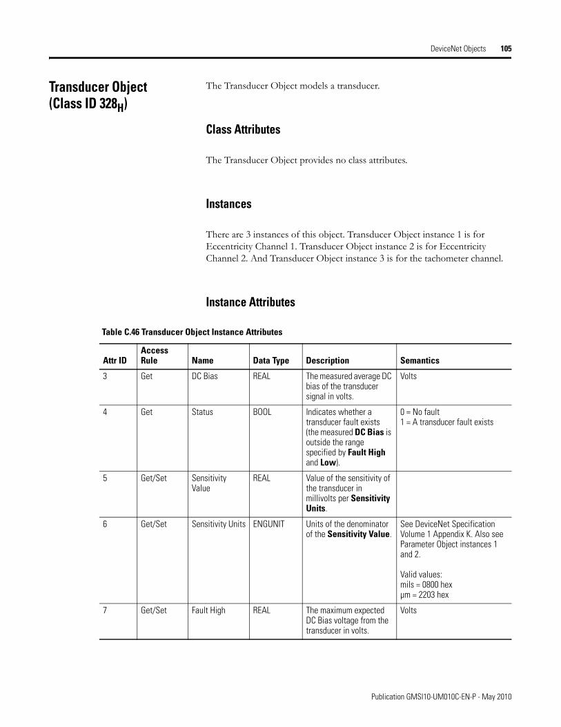
DeviceNet Objects 105
Transducer Object(Class ID 328H)
The Transducer Object models a transducer.
Class Attributes
The Transducer Object provides no class attributes.
Instances
There are 3 instances of this object. Transducer Object instance 1 is for Eccentricity Channel 1. Transducer Object instance 2 is for Eccentricity Channel 2. And Transducer Object instance 3 is for the tachometer channel.
Instance Attributes
Table C.46 Transducer Object Instance Attributes
Attr IDAccess Rule Name Data Type Description Semantics
3 Get DC Bias REAL The measured average DC bias of the transducer signal in volts.
Volts
4 Get Status BOOL Indicates whether a transducer fault exists (the measured DC Bias is outside the range specified by Fault High and Low).
0 = No fault1 = A transducer fault exists
5 Get/Set Sensitivity Value
REAL Value of the sensitivity of the transducer in millivolts per Sensitivity Units.
6 Get/Set Sensitivity Units ENGUNIT Units of the denominator of the Sensitivity Value.
See DeviceNet Specification Volume 1 Appendix K. Also see Parameter Object instances 1 and 2.
Valid values:mils = 0800 hexµm = 2203 hex
7 Get/Set Fault High REAL The maximum expected DC Bias voltage from the transducer in volts.
Volts
Publication GMSI10-UM010C-EN-P - May 2010
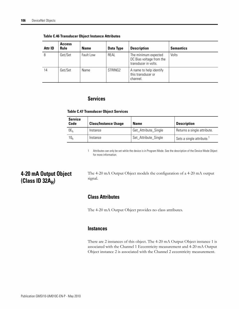
106 DeviceNet Objects
Services
1 Attributes can only be set while the device is in Program Mode. See the description of the Device Mode Object for more information.
4-20 mA Output Object(Class ID 32AH)
The 4-20 mA Output Object models the configuration of a 4-20 mA output signal.
Class Attributes
The 4-20 mA Output Object provides no class attributes.
Instances
There are 2 instances of this object. The 4-20 mA Output Object instance 1 is associated with the Channel 1 Eccentricity measurement and 4-20 mA Output Object instance 2 is associated with the Channel 2 eccentricity measurement.
8 Get/Set Fault Low REAL The minimum expected DC Bias voltage from the transducer in volts.
Volts
14 Get/Set Name STRING2 A name to help identify this transducer or channel.
Table C.46 Transducer Object Instance Attributes
Attr IDAccess Rule Name Data Type Description Semantics
Table C.47 Transducer Object Services
Service Code Class/Instance Usage Name Description
0Eh Instance Get_Attribute_Single Returns a single attribute.
10h Instance Set_Attribute_Single Sets a single attribute.1
Publication GMSI10-UM010C-EN-P - May 2010
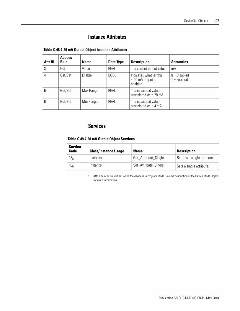
DeviceNet Objects 107
Instance Attributes
Services
1 Attributes can only be set while the device is in Program Mode. See the description of the Device Mode Object for more information.
Table C.48 4-20 mA Output Object Instance Attributes
Attr IDAccess Rule Name Data Type Description Semantics
3 Get Value REAL The current output value. mA
4 Get/Set Enable BOOL Indicates whether this 4-20 mA output is enabled.
0 = Disabled1 = Enabled
5 Get/Set Max Range REAL The measured value associated with 20 mA.
6 Get/Set Min Range REAL The measured value associated with 4 mA.
Table C.49 4-20 mA Output Object Services
Service Code Class/Instance Usage Name Description
0Eh Instance Get_Attribute_Single Returns a single attribute.
10h Instance Set_Attribute_Single Sets a single attribute.1
Publication GMSI10-UM010C-EN-P - May 2010

108 DeviceNet Objects
Publication GMSI10-UM010C-EN-P - May 2010
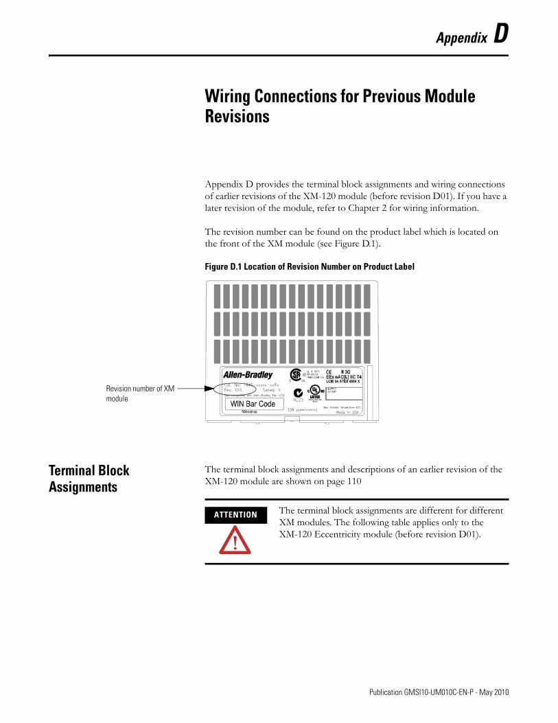
Appendix D
Wiring Connections for Previous Module Revisions
Appendix D provides the terminal block assignments and wiring connections of earlier revisions of the XM-120 module (before revision D01). If you have a later revision of the module, refer to Chapter 2 for wiring information.
The revision number can be found on the product label which is located on the front of the XM module (see Figure D.1).
Figure D.1 Location of Revision Number on Product Label
Terminal Block Assignments
The terminal block assignments and descriptions of an earlier revision of the XM-120 module are shown on page 110
Revision number of XM module
ATTENTION The terminal block assignments are different for different XM modules. The following table applies only to the XM-120 Eccentricity module (before revision D01).
109 Publication GMSI10-UM010C-EN-P - May 2010
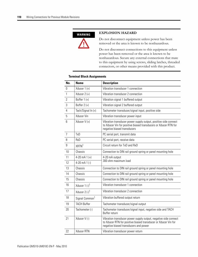
110 Wiring Connections for Previous Module Revisions
WARNING EXPLOSION HAZARD
Do not disconnect equipment unless power has been removed or the area is known to be nonhazardous.
Do not disconnect connections to this equipment unless power has been removed or the area is known to be nonhazardous. Secure any external connections that mate to this equipment by using screws, sliding latches, threaded connectors, or other means provided with this product.
Terminal Block Assignments
No. Name Description
0 Xducer 1 (+) Vibration transducer 1 connection
1 Xducer 2 (+) Vibration transducer 2 connection
2 Buffer 1 (+) Vibration signal 1 buffered output
3 Buffer 2 (+) Vibration signal 2 buffered output
4 Tach/Signal In (+) Tachometer transducer/signal input, positive side
5 Xducer Vin Vibration transducer power input
6 Xducer V (+) Vibration transducer power supply output, positive side connect to Xducer Vin for positive biased transducers or Xducer RTN for negative biased transducers
7 TxD PC serial port, transmit data
8 RxD PC serial port, receive data
9 XRTN1 Circuit return for TxD and RxD
10 Chassis Connection to DIN rail ground spring or panel mounting hole
11 4-20 mA 1 (+) 4-20 mA output 300 ohm maximum load
12 4-20 mA 1 (-)
13 Chassis Connection to DIN rail ground spring or panel mounting hole
14 Chassis Connection to DIN rail ground spring or panel mounting hole
15 Chassis Connection to DIN rail ground spring or panel mounting hole
16 Xducer 1 (-)1 Vibration transducer 1 connection
17 Xducer 2 (-)1 Vibration transducer 2 connection
18 Signal Common1 Vibration buffered output return
19 TACH Buffer Tachometer transducer/signal output
20 Tachometer (-) Tachometer transducer/signal input, negative side and TACH Buffer return
21 Xducer V (-) Vibration transducer power supply output, negative side connect to Xducer RTN for positive biased transducer or Xducer Vin for negative biased transducers and power
22 Xducer RTN Vibration transducer power return
Publication GMSI10-UM010C-EN-P - May 2010
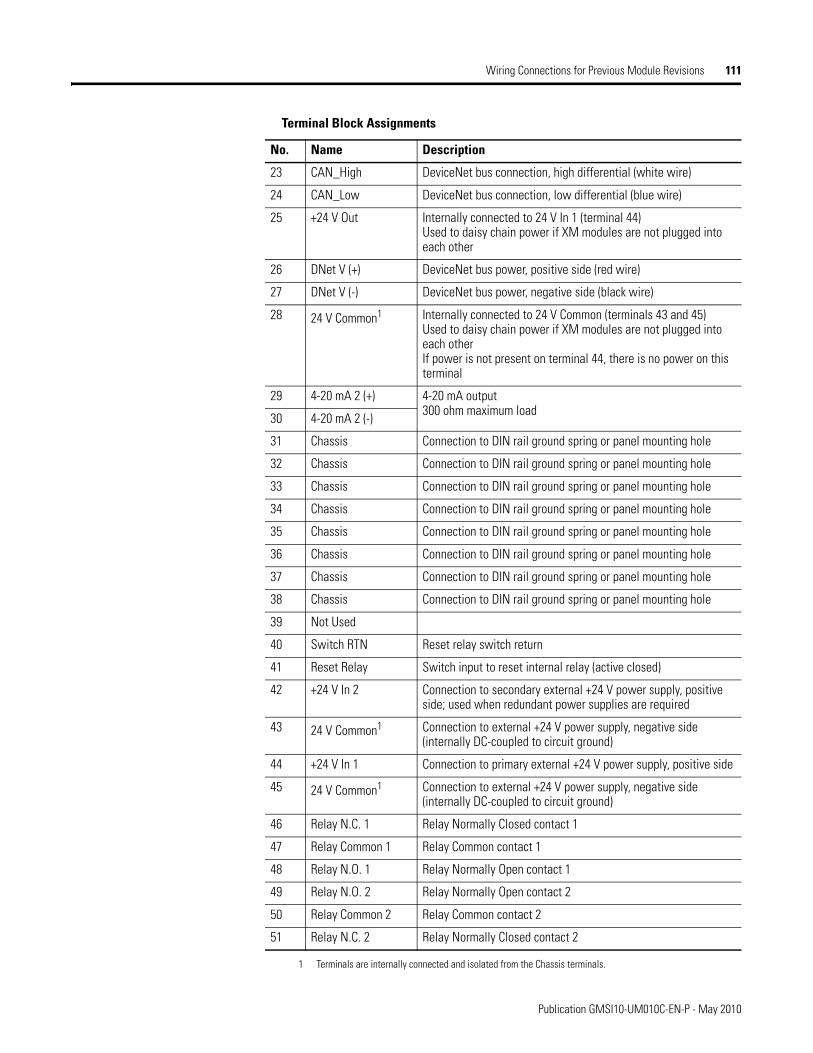
Wiring Connections for Previous Module Revisions 111
1 Terminals are internally connected and isolated from the Chassis terminals.
23 CAN_High DeviceNet bus connection, high differential (white wire)
24 CAN_Low DeviceNet bus connection, low differential (blue wire)
25 +24 V Out Internally connected to 24 V In 1 (terminal 44)Used to daisy chain power if XM modules are not plugged into each other
26 DNet V (+) DeviceNet bus power, positive side (red wire)
27 DNet V (-) DeviceNet bus power, negative side (black wire)
28 24 V Common1 Internally connected to 24 V Common (terminals 43 and 45)Used to daisy chain power if XM modules are not plugged into each other If power is not present on terminal 44, there is no power on this terminal
29 4-20 mA 2 (+) 4-20 mA output300 ohm maximum load
30 4-20 mA 2 (-)
31 Chassis Connection to DIN rail ground spring or panel mounting hole
32 Chassis Connection to DIN rail ground spring or panel mounting hole
33 Chassis Connection to DIN rail ground spring or panel mounting hole
34 Chassis Connection to DIN rail ground spring or panel mounting hole
35 Chassis Connection to DIN rail ground spring or panel mounting hole
36 Chassis Connection to DIN rail ground spring or panel mounting hole
37 Chassis Connection to DIN rail ground spring or panel mounting hole
38 Chassis Connection to DIN rail ground spring or panel mounting hole
39 Not Used
40 Switch RTN Reset relay switch return
41 Reset Relay Switch input to reset internal relay (active closed)
42 +24 V In 2 Connection to secondary external +24 V power supply, positive side; used when redundant power supplies are required
43 24 V Common1 Connection to external +24 V power supply, negative side (internally DC-coupled to circuit ground)
44 +24 V In 1 Connection to primary external +24 V power supply, positive side
45 24 V Common1 Connection to external +24 V power supply, negative side (internally DC-coupled to circuit ground)
46 Relay N.C. 1 Relay Normally Closed contact 1
47 Relay Common 1 Relay Common contact 1
48 Relay N.O. 1 Relay Normally Open contact 1
49 Relay N.O. 2 Relay Normally Open contact 2
50 Relay Common 2 Relay Common contact 2
51 Relay N.C. 2 Relay Normally Closed contact 2
Terminal Block Assignments
No. Name Description
Publication GMSI10-UM010C-EN-P - May 2010
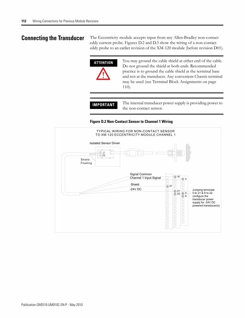
112 Wiring Connections for Previous Module Revisions
Connecting the Transducer The Eccentricity module accepts input from any Allen-Bradley non-contact eddy current probe. Figures D.2 and D.3 show the wiring of a non-contact eddy probe to an earlier revision of the XM-120 module (before revision D01).
Figure D.2 Non-Contact Sensor to Channel 1 Wiring
ATTENTION You may ground the cable shield at either end of the cable. Do not ground the shield at both ends. Recommended practice is to ground the cable shield at the terminal base and not at the transducer. Any convenient Chassis terminal may be used (see Terminal Block Assignments on page 110).
IMPORTANT The internal transducer power supply is providing power to the non-contact sensor.
TYPICAL WIRING FOR NON-CONTACT SENSORTO XM-120 ECCENTRICITY MODULE CHANNEL 1
COMSIG-24
Channel 1 Input Signal
-24V DC
016
226
Signal Common
215
Jumping terminals 5 to 21 & 6 to 22configure the transducer powersupply for -24V DCpowered transducer(s)
Isolated Sensor Driver
Shield
ShieldFloating
37
Publication GMSI10-UM010C-EN-P - May 2010
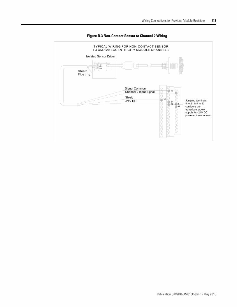
Wiring Connections for Previous Module Revisions 113
Figure D.3 Non-Contact Sensor to Channel 2 Wiring
TYPICAL WIRING FOR NON-CONTACT SENSORTO XM-120 ECCENTRICITY MODULE CHANNEL 2
COMSIG-24
Channel 2 Input Signal
-24V DC
117
226
Signal Common
215
Jumping terminals 5 to 21 & 6 to 22 configure the transducer powersupply for -24V DCpowered transducer(s)
Isolated Sensor Driver
Shield
ShieldFloating
38
Publication GMSI10-UM010C-EN-P - May 2010

114 Wiring Connections for Previous Module Revisions
Publication GMSI10-UM010C-EN-P - May 2010
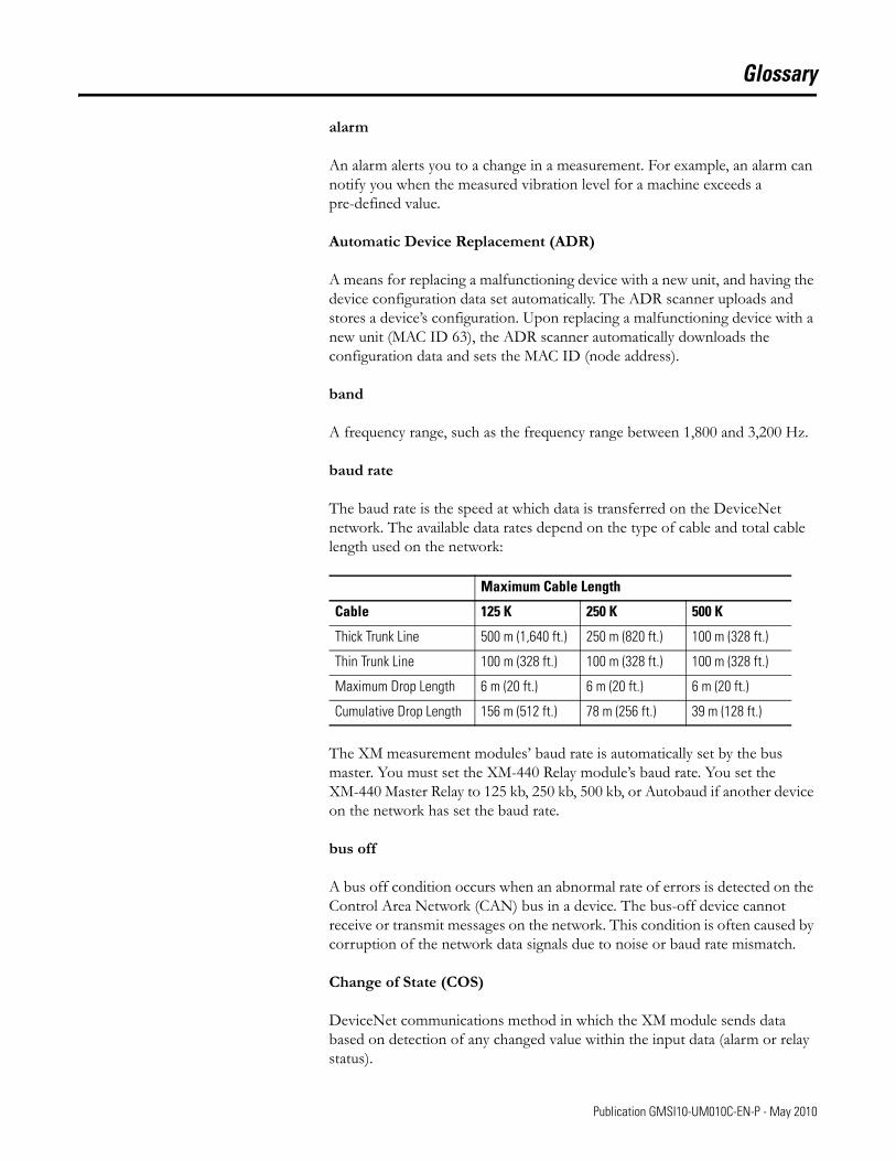
Glossary
alarm
An alarm alerts you to a change in a measurement. For example, an alarm can notify you when the measured vibration level for a machine exceeds a pre-defined value.
Automatic Device Replacement (ADR)
A means for replacing a malfunctioning device with a new unit, and having the device configuration data set automatically. The ADR scanner uploads and stores a device’s configuration. Upon replacing a malfunctioning device with a new unit (MAC ID 63), the ADR scanner automatically downloads the configuration data and sets the MAC ID (node address).
band
A frequency range, such as the frequency range between 1,800 and 3,200 Hz.
baud rate
The baud rate is the speed at which data is transferred on the DeviceNet network. The available data rates depend on the type of cable and total cable length used on the network:
The XM measurement modules’ baud rate is automatically set by the bus master. You must set the XM-440 Relay module’s baud rate. You set the XM-440 Master Relay to 125 kb, 250 kb, 500 kb, or Autobaud if another device on the network has set the baud rate.
bus off
A bus off condition occurs when an abnormal rate of errors is detected on the Control Area Network (CAN) bus in a device. The bus-off device cannot receive or transmit messages on the network. This condition is often caused by corruption of the network data signals due to noise or baud rate mismatch.
Change of State (COS)
DeviceNet communications method in which the XM module sends data based on detection of any changed value within the input data (alarm or relay status).
Maximum Cable Length
Cable 125 K 250 K 500 K
Thick Trunk Line 500 m (1,640 ft.) 250 m (820 ft.) 100 m (328 ft.)
Thin Trunk Line 100 m (328 ft.) 100 m (328 ft.) 100 m (328 ft.)
Maximum Drop Length 6 m (20 ft.) 6 m (20 ft.) 6 m (20 ft.)
Cumulative Drop Length 156 m (512 ft.) 78 m (256 ft.) 39 m (128 ft.)
115 Publication GMSI10-UM010C-EN-P - May 2010
Glossary 116
current configuration
The current configuration is the most recently loaded set of configuration parameters in the XM module’s memory. When power is cycled, the current configuration is loaded with either the saved configuration (in EEPROM) or the factory defaults (if there is no saved configuration). In addition, the current configuration contains any configuration changes that have been downloaded to the module since power was applied.
DeviceNet network
A DeviceNet network uses a producer/consumer Controller Area Network (CAN) to connect devices (for example, XM modules). A DeviceNet network can support a maximum of 64 devices. Each device is assigned a unique node address (MAC ID) and transmits data on the network at the same baud rate.
A cable is used to connect devices on the network. It contains both the signal and power wires. General information about DeviceNet and the DeviceNet specification are maintained by the Open DeviceNet Vendor’s Association (ODVA). ODVA is online at http://www.odva.org.
disarm state
See Program mode.
eccentricity
Eccentricity is the measurement of shaft bow at slow-roll speed, which can be caused by any or a combination of:
• Fixed mechanical bow• Temporary thermal bow• Gravity bow
EEPROM
See NVS (Non-Volatile Storage).
Electronic Data Sheet (EDS) Files
EDS files are simple text files that are used by network configuration tools such as RSNetWorx for DeviceNet to describe products so that you can easily commission them on a network. EDS files describe a product device type, revision, and configurable parameters.
Publication GMSI10-UM010C-EN-P - May 2010
Glossary 117
Help window
A window that contains help topics that describe the operation of a program. These topics may include:
• An explanation of a command.• A description of the controls in a dialog box or property page.• Instructions for a task.• Definition of a term.
MAC ID
See node address.
master device
A device which controls one or more slave devices. The XM-440 Master Relay module is a master device.
Node Address
A DeviceNet network can have as many as 64 devices connected to it. Each device on the network must have a unique node address between 0 and 63. Node address 63 is the default used by uncommissioned devices. Node address is sometimes called "MAC ID."
NVS (Non-Volatile Storage)
NVS is the permanent memory of an XM module. Modules store parameters and other information in NVS so that they are not lost when the module loses power (unless Auto Save is disabled). NVS is sometimes called "EEPROM."
online help
Online help allows you to get help for your program on the computer screen by pressing F1. The help that appears in the Help window is context sensitive, which means that the help is related to what you are currently doing in the program.
peak-to-peak eccentricity
Measurement that measures the difference between the positive and the negative extremes of the rotor bow.
Polled
DeviceNet communications method in which module sends data in response to a poll request from a master device.
Publication GMSI10-UM010C-EN-P - May 2010
Glossary 118
Program mode
The XM module is idle. Typically this occurs when the module configuration settings are being updated with the XM Configuration program. In Program mode, the signal processing/measurement process is stopped. The status of the alarms is set to the disarm state to prevent a false alert or danger status.
Run mode
In Run mode, the module collects measurement data and monitors each measurement device.
slave device
A device that receives and responds to messages from a Master device but does not initiate communication. Slave devices include the XM measurement modules, such as the XM-120 Eccentricity module and the XM-320 Position module.
transducer
A transducer is a device for making measurements. These include accelerometers, velocity pickups, displacement probes, and temperature sensors.
virtual relay
A virtual relay is a non-physical relay. It has the same capabilities (monitor alarms, activation delay, change status) as a physical relay only without any physical or electrical output. The virtual relay provides additional relay status inputs to a controller, PLC, or an XM-440 Master Relay module (firmware revision 5.0 and later).
XM configuration
XM configuration is a collection of user-defined parameters for XM modules.
XM Serial Configuration Utility software
XM Serial Configuration Utility software is a tool for monitoring and configuring XM modules. It can be run on computers running Windows 2000 service pack 2, Windows NT 4.0 service pack 6, or Windows XP operating systems.
Publication GMSI10-UM010C-EN-P - May 2010
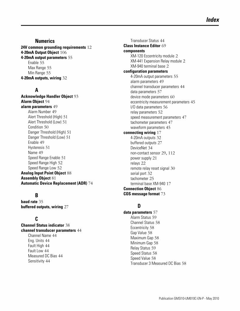
Index
Numerics24V common grounding requirements 124-20mA Output Object 1064-20mA output parameters 55
Enable 55Max Range 55Min Range 55
4-20mA outputs, wiring 32
AAcknowledge Handler Object 93Alarm Object 94alarm parameters 49
Alarm Number 49Alert Threshold (High) 51Alert Threshold (Low) 51Condition 50Danger Threshold (High) 51Danger Threshold (Low) 51Enable 49Hysteresis 51Name 49Speed Range Enable 51Speed Range High 52Speed Range Low 52
Analog Input Point Object 88Assembly Object 81Automatic Device Replacement (ADR) 74
Bbaud rate 35buffered outputs, wiring 27
CChannel Status indicator 38channel transducer parameters 44
Channel Name 44Eng. Units 44Fault High 44Fault Low 44Measured DC Bias 44Sensitivity 44
Transducer Status 44Class Instance Editor 69components
XM-120 Eccentricity module 2XM-441 Expansion Relay module 2XM-940 terminal base 2
configuration parameters4-20mA output parameters 55alarm parameters 49channel transducer parameters 44data parameters 57device mode parameters 60eccentricity measurement parameters 45I/O data parameters 56relay parameters 52speed measurement parameters 47tachometer parameters 47waveform parameters 45
connecting wiring 174-20mA outputs 32buffered outputs 27DeviceNet 34non-contact sensor 29, 112power supply 21relays 22remote relay reset signal 30serial port 32tachometer 25terminal base XM-940 17
Connection Object 86COS message format 73
Ddata parameters 57
Alarm Status 59Channel Status 58Eccentricity 58Gap Value 58Maximum Gap 58Minimum Gap 58Relay Status 59Speed Status 58Speed Value 58Transducer 3 Measured DC Bias 58
Publication GMSI10-UM010C-EN-P - May 2010
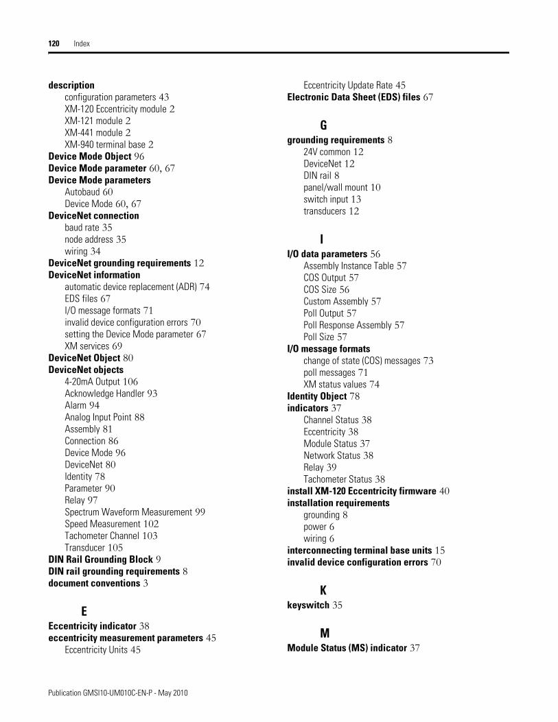
120 Index
descriptionconfiguration parameters 43XM-120 Eccentricity module 2XM-121 module 2XM-441 module 2XM-940 terminal base 2
Device Mode Object 96Device Mode parameter 60, 67Device Mode parameters
Autobaud 60Device Mode 60, 67
DeviceNet connectionbaud rate 35node address 35wiring 34
DeviceNet grounding requirements 12DeviceNet information
automatic device replacement (ADR) 74EDS files 67I/O message formats 71invalid device configuration errors 70setting the Device Mode parameter 67XM services 69
DeviceNet Object 80DeviceNet objects
4-20mA Output 106Acknowledge Handler 93Alarm 94Analog Input Point 88Assembly 81Connection 86Device Mode 96DeviceNet 80Identity 78Parameter 90Relay 97Spectrum Waveform Measurement 99Speed Measurement 102Tachometer Channel 103Transducer 105
DIN Rail Grounding Block 9DIN rail grounding requirements 8document conventions 3
EEccentricity indicator 38eccentricity measurement parameters 45
Eccentricity Units 45
Eccentricity Update Rate 45Electronic Data Sheet (EDS) files 67
Ggrounding requirements 8
24V common 12DeviceNet 12DIN rail 8panel/wall mount 10switch input 13transducers 12
II/O data parameters 56
Assembly Instance Table 57COS Output 57COS Size 56Custom Assembly 57Poll Output 57Poll Response Assembly 57Poll Size 57
I/O message formatschange of state (COS) messages 73poll messages 71XM status values 74
Identity Object 78indicators 37
Channel Status 38Eccentricity 38Module Status 37Network Status 38Relay 39Tachometer Status 38
install XM-120 Eccentricity firmware 40installation requirements
grounding 8power 6wiring 6
interconnecting terminal base units 15invalid device configuration errors 70
Kkeyswitch 35
MModule Status (MS) indicator 37
Publication GMSI10-UM010C-EN-P - May 2010
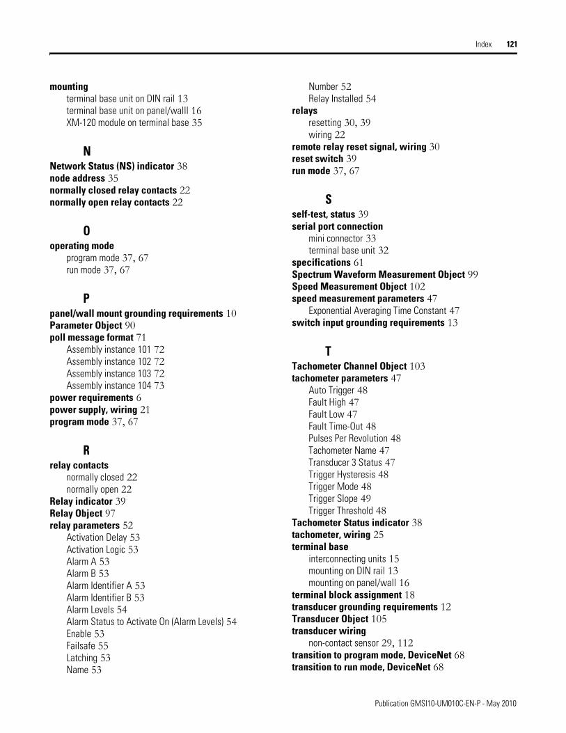
Index 121
mountingterminal base unit on DIN rail 13terminal base unit on panel/walll 16XM-120 module on terminal base 35
NNetwork Status (NS) indicator 38node address 35normally closed relay contacts 22normally open relay contacts 22
Ooperating mode
program mode 37, 67run mode 37, 67
Ppanel/wall mount grounding requirements 10Parameter Object 90poll message format 71
Assembly instance 101 72Assembly instance 102 72Assembly instance 103 72Assembly instance 104 73
power requirements 6power supply, wiring 21program mode 37, 67
Rrelay contacts
normally closed 22normally open 22
Relay indicator 39Relay Object 97relay parameters 52
Activation Delay 53Activation Logic 53Alarm A 53Alarm B 53Alarm Identifier A 53Alarm Identifier B 53Alarm Levels 54Alarm Status to Activate On (Alarm Levels) 54Enable 53Failsafe 55Latching 53Name 53
Number 52Relay Installed 54
relaysresetting 30, 39wiring 22
remote relay reset signal, wiring 30reset switch 39run mode 37, 67
Sself-test, status 39serial port connection
mini connector 33terminal base unit 32
specifications 61Spectrum Waveform Measurement Object 99Speed Measurement Object 102speed measurement parameters 47
Exponential Averaging Time Constant 47switch input grounding requirements 13
TTachometer Channel Object 103tachometer parameters 47
Auto Trigger 48Fault High 47Fault Low 47Fault Time-Out 48Pulses Per Revolution 48Tachometer Name 47Transducer 3 Status 47Trigger Hysteresis 48Trigger Mode 48Trigger Slope 49Trigger Threshold 48
Tachometer Status indicator 38tachometer, wiring 25terminal base
interconnecting units 15mounting on DIN rail 13mounting on panel/wall 16
terminal block assignment 18transducer grounding requirements 12Transducer Object 105transducer wiring
non-contact sensor 29, 112transition to program mode, DeviceNet 68transition to run mode, DeviceNet 68
Publication GMSI10-UM010C-EN-P - May 2010
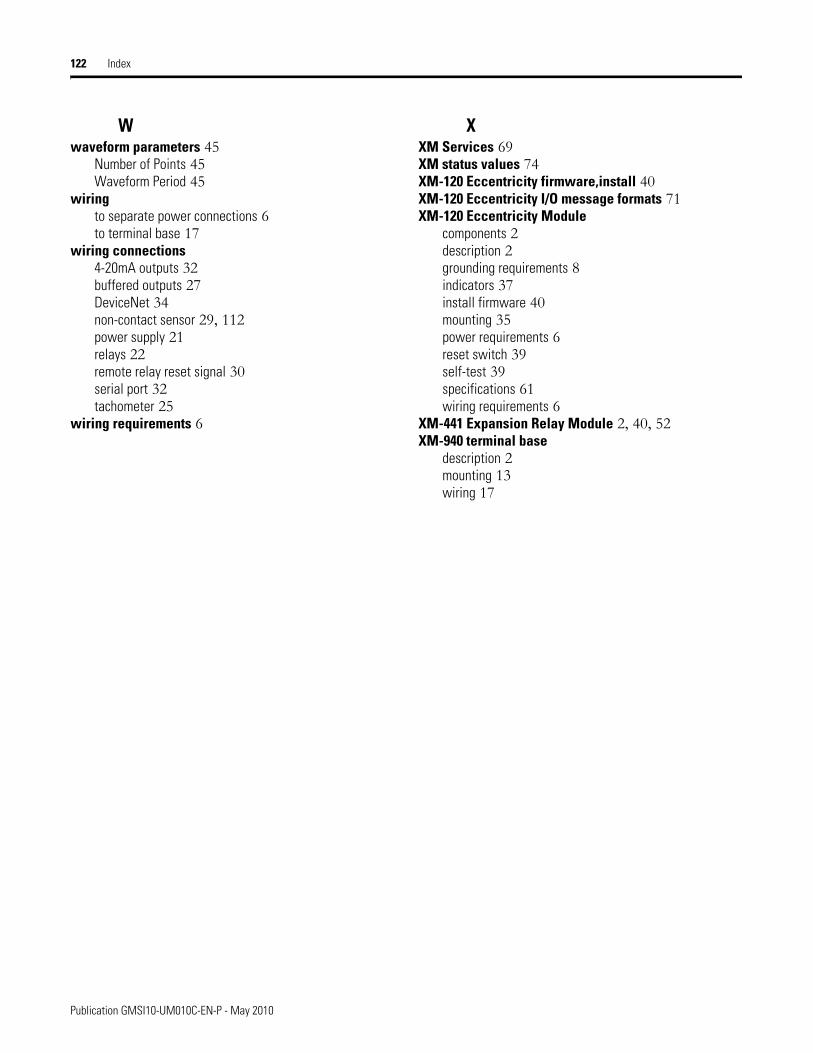
122 Index
Wwaveform parameters 45
Number of Points 45Waveform Period 45
wiringto separate power connections 6to terminal base 17
wiring connections4-20mA outputs 32buffered outputs 27DeviceNet 34non-contact sensor 29, 112power supply 21relays 22remote relay reset signal 30serial port 32tachometer 25
wiring requirements 6
XXM Services 69XM status values 74XM-120 Eccentricity firmware,install 40XM-120 Eccentricity I/O message formats 71XM-120 Eccentricity Module
components 2description 2grounding requirements 8indicators 37install firmware 40mounting 35power requirements 6reset switch 39self-test 39specifications 61wiring requirements 6
XM-441 Expansion Relay Module 2, 40, 52XM-940 terminal base
description 2mounting 13wiring 17
Publication GMSI10-UM010C-EN-P - May 2010
Publication GMSI10-UM010C-EN-P - May 2010 123Supersedes Publication GMSI10-UM010B-EN-E - January 2007 Copyright © 2010 Rockwell Automation, Inc. All rights reserved. Printed in the U.S.A.
Rockwell Automation Support
Rockwell Automation provides technical information on the Web to assist you in using its products. At http://support.rockwellautomation.com, you can find technical manuals, a knowledge base of FAQs, technical and application notes, sample code and links to software service packs, and a MySupport feature that you can customize to make the best use of these tools.
For an additional level of technical phone support for installation, configuration, and troubleshooting, we offer TechConnect support programs. For more information, contact your local distributor or Rockwell Automation representative, or visit http://support.rockwellautomation.com.
Installation Assistance
If you experience a problem within the first 24 hours of installation, please review the information that's contained in this manual. You can also contact a special Customer Support number for initial help in getting your product up and running.
New Product Satisfaction Return
Rockwell Automation tests all of its products to ensure that they are fully operational when shipped from the manufacturing facility. However, if your product is not functioning and needs to be returned, follow these procedures.
United States 1.440.646.3434Monday – Friday, 8am – 5pm EST
Outside United States
Please contact your local Rockwell Automation representative for any technical support issues.
United States Contact your distributor. You must provide a Customer Support case number (call the phone number above to obtain one) to your distributor in order to complete the return process.
Outside United States
Please contact your local Rockwell Automation representative for the return procedure.