Embed Size (px)
Citation preview

GESensing & Inspection Technologies Remote Visual Inspection
XL Vu™ VideoProbe®
Operating Manual

XL Go™ VideoProbe® 1
Table of Contents
ContentsAbout this Manual ........................................................................3Corded XL Vu ...............................................................................4Indicators, and Connectors...........................................................5Battery XL Vu ................................................................................6Indicators, and Connectors...........................................................7Controls ........................................................................................8Symbols and Terms ....................................................................10General Warnings .......................................................................10General Cautions........................................................................11Battery Warnings (Battery XL Vu Only) ......................................12Symboles et termes employés ...................................................13Avertissements généraux ...........................................................13Mentions générales « Attention » ...............................................13Avertissements liés à la batterie .................................................14System Removal ........................................................................16System Power On ......................................................................17System Power Off ......................................................................18System Storage ..........................................................................18Mounting Accessories.................................................................19Battery .......................................................................................20Battery Charge Level .................................................................21Charging Battery.........................................................................21Saving Images and Video ...........................................................22GO TO Menu ..............................................................................25
GO TO > File Manager ........................................................25GO TO > Eject Hardware .....................................................26GO TO > Zoom Level ...........................................................27GO TO > Light Output ..........................................................28GO TO > Invert ...................................................................29
Live Main Menu ..........................................................................30Live Main Menu > Light Output ............................................30Live Main Menu > Image Control .........................................31Live Main Menu > Annotation ..............................................35Live Main Menu > File Manager ..........................................40Live Main Menu > Eject Hardware ......................................41Live Main Menu > Setup .....................................................42Live Main Menu > Setup > Screen/Display Setup ...............43
Date / Time ....................................................................45Logo ...............................................................................46Text Color ......................................................................47

Table of Contents
2 XL Go™ VideoProbe®
Video Record Setup ......................................................49Still Image Setup ..........................................................52
Live Main Menu > Setup > Audio Annotation Setup .............56Live Main Menu > Setup > Language Setup ........................58Live Main Menu > Setup > System Tools .............................59
Steering the VideoProbe ............................................................61Articulation Lock .........................................................................61Articulation Home .......................................................................62Freeze Frame .............................................................................63Freeze Frame Menu ...................................................................64File Manager...............................................................................65
File Manager > Recall ..........................................................65Recalled Image Menu ..........................................................66File Manager > Copy ............................................................67File Manager > Delete ..........................................................68File Manager > Create Folder ..............................................69File Manager > Rename ......................................................70File Manager > Still Image Setup .........................................71File Manager > Video Record Setup ....................................71
Video Playback Menu .................................................................72Inspecting and Cleaning the System ..........................................73Cleaning Optical Tips..................................................................73Sales and Technical Support ......................................................74Web Site .....................................................................................74Service........................................................................................75Technical Specifications: ............................................................76A.Optical Tip Table ......................................................................80B.Chemical Compatibility............................................................82C.Warranty .................................................................................82D.Environmental Compliance ....................................................83E.Agency Certifications ..............................................................84F.Creating a Personalized Logo File...........................................86

XL Vu™ VideoProbe® 3
Introduction
About this Manual
This manual and the related equipment is intended for visual inspection technicians with a basic understanding of inspection principles and practices, and who are familiar with basic computer operations, but who may not have experience with a video borescope system.
The manual contains complete setup, operating, and maintenance instructions for the XL Vu video borescope system. The manual also provides a product overview, step-by-step procedures, and reference information.
To ensure operator safety, please read and understand this manual prior to using the system.
For additional assistance, go to www.geinspectiontechnologies.com for a complete listing of contact information.
Standard Corded Version Standard Battery Version XL Vu XL Vu XL Vu Storage Case XL Vu Storage Case Optical Tip Storage Case Optical Tip Storage Case 4 GB USB Thumbdrive 4 GB USB Thumbdrive Owner’s Manual Owner’s Manual Quickstart Card Quickstart Card Documentation CD-ROM Documentation CD-ROM Power Supply Brick 2-hour Li-Ion Battery AC Adapter/Battery Charger
Optional Accessories Headset Neck Strap VGA Video Cable 16 GB USB Thumbdrive IT Gripper Belt Clip IT Rigidizer Sun Visor Mini-Magic Arm Mounting Kit Car Cord Handset Holder Soft Case Spare 4 hour battery (Battery Version Only)

Introduction
4 XL Vu™ VideoProbe®
2
3
4
6
7
1
8
XL Vu
5
Corded XL Vu
XL Vu™ VideoProbe® 5
Introduction
Indicators, and Connectors
1 LCD Screen
2 Integrated 2.5 mm headset/microphone jack
3 VGA output
4 Controls
5 AC to DC Power Supply 6 USB Bay 7 Insertion Tube Strap
8 Insertion Tube
Introduction
6 XL Vu™ VideoProbe®
2
3
4
5
6
8
7
9
10
1
11
XL Vu
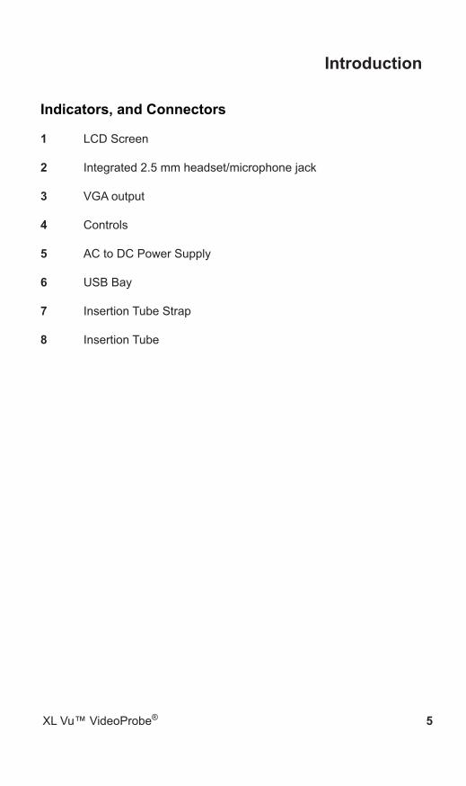
Battery XL Vu

XL Vu™ VideoProbe® 7
Introduction
Indicators, and Connectors
1 LCD Screen
2 Integrated 2.5 mm headset/microphone jack
3 VGA output
4 Controls
5 2-hour Lithium Ion Battery
6 Battery Locking Screw
7 Battery Charge Indicator
8 AC to DC Adaptor Input
9 USB Bay 10 Insertion Tube Strap 11 Insertion Tube

Introduction
8 XL Vu™ VideoProbe®
Controls
The following buttons control basic and advanced operation of the XL Vu VideoProbe.
1
2
3
4
5
6
XL Vu

XL Vu™ VideoProbe® 9
Introduction
1 Left Soft Key Activates screen command listed on system LCD. This key will most frequently return the user BACK one screen.
2 Power/Exit Turns system power on/off. Also used to exit menus, return to live/frozen video and disable image control features.
3 JoystickControls articulation. Press to activate the Live Main Menu, Recalled Image Menu, and Freeze Frame Menu. Push the joystick left/right/up/down to navigate menus and sub-menus.
4 Steering Control Press and release to keep bending neck locked in place after the joystick is released. A lock will appear on the LCD when enabled. Press and release again to unlock the steering control. The lock will disappear from LCD when disabled. Also, press and hold to engage HOME function to straighten bending neck. A blinking Home icon will appear on the LCD when enabled. This icon will disappear when finished.
5 Freeze/Enter Freezes the image on-screen. Also acts as enter key for selecting options.
6 Right Soft Key Activates screen command listed on system LCD. This key will most frequently serve to SELECT active menu choices.
10 XL Vu™ VideoProbe®
Safety Information
Note: Before using or servicing the system, read and understand the following safety information.
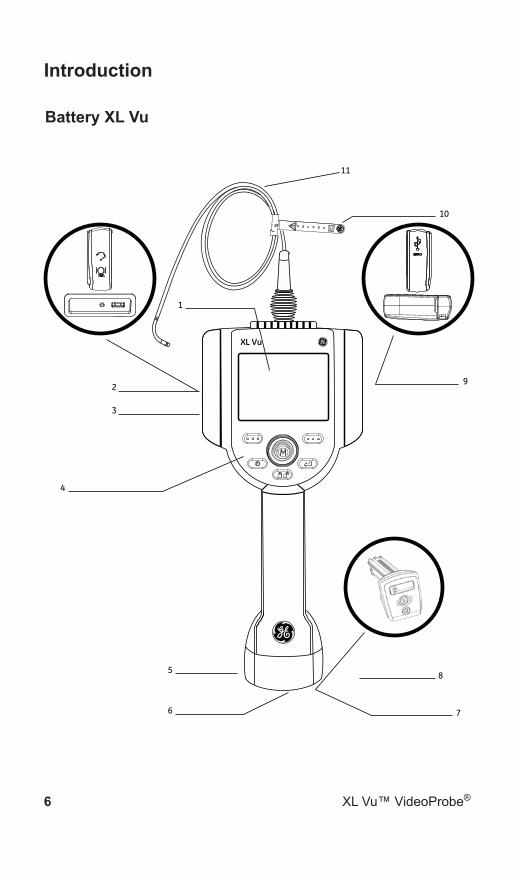
Symbols and Terms
The following symbols appear on the product:
See accompanying documentation.
General WarningsThe following warning statements apply to use of the system in general. Warning statements that apply specifically to particular procedures appear in the corresponding sections of the manual.
Do not allow the conductive insertion tube, system or its working tools to come in direct contact with any voltage or current source. Prevent all contact with live electrical conductors or terminals. Damage to the equipment and/or electrical shock to the operator may result.
Do not use this system in explosive environments
USE PROPERLY. Using any piece of this equipment in a manner not specified by the manufacturer may impair the product’s ability to protect the user from harm.
XL Vu power supply is rated for indoor use only.

XL Vu™ VideoProbe® 11
Safety Information
General Cautions
The following caution statements apply to use of the XL Vu device in general. Caution statements that apply specifically to particular procedures appear in the corresponding sections of the manual.
HANDLE PROBE CAREFULLY. Keep the insertion tube away from sharp objects that might penetrate its outer sheath. Keep the whole insertion tube as straight as possible during operation; loops or bends anywhere in the tube decrease its ability to steer the probe tip. Avoid bending the insertion tube sharply.
Note: Always use the Home button to straighten the bending neck before withdrawing insertion tube from inspection area or putting probe away. Never pull, twist, or straighten the bending neck by hand; internal damage may result. At the first sign of damage, return the probe for repair.
Certain substances may damage the probe. For a list of substances that are safe for the probe, see “Chemical Compatibility” in the Appendix.

12 XL Vu™ VideoProbe®
Safety Information
Battery Warnings (Battery XL Vu Only)
Only use the battery (XLGOABATTA or XLGOABATTB) and power supply (XLGOACHGR) specified for use with the XL Vu system.
Before use, thoroughly review the instructions in this manual for the bat-tery and battery charger to fully understand the information contained in them, and observe the instructions during use.
WARNING
Do not place the battery in fire or exceed the battery operating • temperature.Do not pierce the battery with nails, strike the battery with a hammer, • step on the battery, or otherwise subject it to strong impacts or shocks. Do not expose the battery to water or salt water, or allow the battery • to get wet.Do not disassemble or modify the battery. •
Battery Communication Error. Contact Customer Service at +1 315 554 2000.
Using the battery outside its recommended operating range will result in degradation of the performance and service life. When storing the battery, be sure to remove it from the base unit.
Recommended temperature range for Li-ion battery operation.Discharge (when using the instrument): : -20˚ C to 46˚ CRecharging : 0˚ C to 40˚ CStorage : -25˚ C to +60˚ C

XL Vu™ VideoProbe® 13
Safety Information
Remarque : avant l’utilisation ou l’entretien du système, vous devez lire et comprendre les informations de sécurité qui suivent.
Symboles et termes employés
Les symboles suivants sont apposés sur le produit :
Voir la documentation jointe.
Avertissements générauxLes avertissements suivants s’appliquent à l’utilisation du système en général. Les avertissements qui s’appliquent spécifiquement à des procédures particulières sont indiqués dans les sections correspondantes de ce manuel.
Le système XL Vu et les outils de travail qui l’accompagnent ne doivent jamais entrer en contact direct avec une source de tension ou de courant. Évitez tout contact avec des conducteurs ou des bornes électriques sous tension. L’équipement risquerait d’être endommagé, ou l’opérateur de subir un choc électrique.
N’utilisez pas ce système dans un environnement à risque d’explosion.
UTILISER CORRECTEMENT. Si un élément de cet équipement est utilisé d’une manière non indiquée par le fabricant, l’utilisateur peut ne plus être protégé des risques de blessure.
Mentions générales « Attention »
Les mentions « Attention » qui suivent s’appliquent à l’utilisation de l’appareil XL Vu en général. Les mentions « Attention » qui s’appliquent spécifiquement à des procédures particulières sont indiquées dans les sections correspondantes du manuel.
MANIPULER LA SONDE AVEC PRÉCAUTION. Maintenez la gaine de la sonde à l’écart d’objets pointus ou tranchants qui risqueraient

14 XL Vu™ VideoProbe®
Safety Information
de traverser son fourreau. Maintenez toute la gaine aussi droite que possible pendant l’utilisation : en cas de boucle ou de courbure, il est plus difficile de piloter le bout de la sonde. Évitez de trop courber la gaine.
Remarque : utilisez toujours le bouton de rangement pour redresser le béquillage avant de rétracter la gaine de la zone d’inspection ou de ranger la sonde. Ne manipulez jamais le béquillage à la main pour le tirer, le courber ou le redresser : vous risqueriez de l’endommager à l’intérieur. Envoyez la sonde en réparation au premier signe d’endommagement.
Certaines substances risquent d’endommager la sonde. Pour consulter la liste des substances sans danger pour la sonde, voir Compatibilité Chimique en annexe.
Avertissements liés à la batterie
Utilisez uniquement la batterie (XLGOABATTA or XLGOABATTB) et l’alimentation (XLGOACHGR) spécifiées pour être utilisées avec le système XL Vu.
Avant utilisation, lisez attentivement les instructions contenues dans ce manuel relatives à la batterie et au chargeur de batterie pour bien les comprendre, et respectez ces instructions pendant l’utilisation de l’appareil.
AVERTISSEMENT
Ne jetez pas la batterie au feu et ne dépassez pas sa température • de fonctionnement.Ne percez pas la batterie avec des clous, ne la frappez pas avec • un marteau, ne marchez pas dessus et ne la soumettez pas à des impacts ou des chocs violents. N’exposez pas la batterie à l’eau douce ou salée, et évitez de la • mouiller.Ne désassemblez pas la batterie et ne la modifiez pas. •
Erreur de communication de la batterie. Veuillez contacter le Service clientèle au numéro +1 315 554 2000. L’utilisation de la batterie en dehors de la plage de fonctionnement recommandée entraînerait une dégradation de ses performances et de

XL Vu™ VideoProbe® 15
Safety Information
sa longévité. Lorsque vous stockez la batterie, veillez à la retirer de sa base.
Plage de température recommandée pour le fonctionnement de la batterie Lithium-Ion.
Décharge (à l’utilisation de l’appareil) : -20˚C à +46˚CRecharge , 0˚C à +40˚CStockage, -25˚C à +60˚C

16 XL Vu™ VideoProbe®
Getting Started
System Removal
Gently remove the insertion tube and handset from the storage case.

XL Vu™ VideoProbe® 17
Getting Started
System Power On
Press and hold the Power/Exit key briefly to power on. The buttons and Liquid Crystal Display (LCD) will light and begin the power-up sequence. After approximately 30 seconds, the system screen will display live video and screen prompts. The system is now ready for use.
Note: All batteries are shipped with a partial charge. Batteries should be fully charged prior to use.
RECORD GOTO
XL Vu

18 XL Vu™ VideoProbe®
Getting Started
System Power Off
Press and hold the Power/Exit key until the “SYSTEM SHUTTING DOWN” message appears. Key illumination and LED probe lights will go out when system is completely powered down.
System Storage
Carefully coil the insertion tube into the storage area. Place the XL Vu handset into the designated foam cutout. LCD screen should face up.

XL Vu™ VideoProbe® 19
Getting Started
Mounting Accessories
Assemble the optional mounting accessories by screwing together the mini magic clamp, swivel ball, and handset holder.
Secure the XL Vu mini magic clamp and place the XL Vu system in the handset holder.

20 XL Vu™ VideoProbe®
Getting Started
XL Vu
Battery
Installing Battery Insert the battery into the handset. The battery is installed properly when the latching mechanism is engaged.
Note: Do not force the battery into the handset, as damage may occur. The battery is keyed and may only be installed in the proper orientation.
Removing Battery Using a slotted screw driver or coin, turn the locking screw counterclockwise and release the battery.
Note: Do not remove battery while system is operating.
Battery Locking Screw

XL Vu™ VideoProbe® 21
Getting Started
Battery Charge Level
Check the battery charge by pressing the battery symbol on the front of the battery. Each light represents approximately 20% of the battery charge capacity.
Charging Battery
Plug the included XLGOACHGR power adaptor into a suitable AC power source and connect the DC output of the battery charger into the XL Vu battery. The LED battery lights will illuminate according to the amount of charge attained. The system may operate while charging.
The battery may also be charged while disconnected from the system.When the battery is fully charged, the LED battery lights will turn off.
Note: Battery run time typically equals battery charge time; therefore, a four hour battery will take approximately four hours to charge.
DC Battery Charging Jack
Charge Indicator LED’s

22 XL Vu™ VideoProbe®
Getting Started
Saving Images and Video
Still Images
To capture a still image, compose the picture and press and release Freeze/Enter. Press the right soft key with SAVE on the
LCD above to save to the default location. Alternately, from live video, press and hold Freeze/Enter to quick-save.
Video
To record live video, press and hold the left soft key labeled RECORD on the LCD above. A red record symbol will appear in the upper right hand corner. When the video is stopped, it will automatically save to the default location.
XL Vu™ VideoProbe® 23
Getting Started
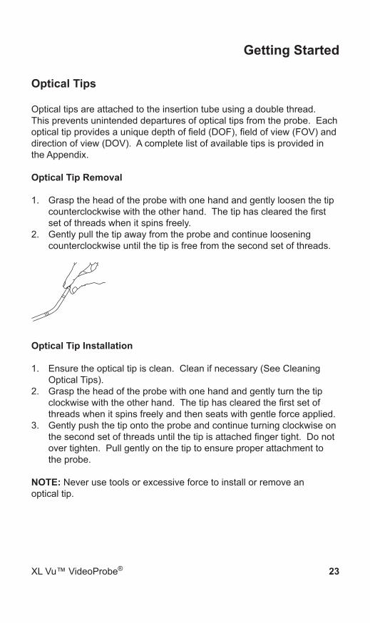
Optical Tips Optical tips are attached to the insertion tube using a double thread. This prevents unintended departures of optical tips from the probe. Each optical tip provides a unique depth of field (DOF), field of view (FOV) and direction of view (DOV). A complete list of available tips is provided in the Appendix.
Optical Tip Removal
Grasp the head of the probe with one hand and gently loosen the tip 1. counterclockwise with the other hand. The tip has cleared the first set of threads when it spins freely.Gently pull the tip away from the probe and continue loosening 2. counterclockwise until the tip is free from the second set of threads.
Optical Tip Installation
Ensure the optical tip is clean. Clean if necessary (See Cleaning 1. Optical Tips).Grasp the head of the probe with one hand and gently turn the tip 2. clockwise with the other hand. The tip has cleared the first set of threads when it spins freely and then seats with gentle force applied.Gently push the tip onto the probe and continue turning clockwise on 3. the second set of threads until the tip is attached finger tight. Do not over tighten. Pull gently on the tip to ensure proper attachment to the probe.
NOTE: Never use tools or excessive force to install or remove an optical tip.
24 XL Vu™ VideoProbe®
Getting Started
Tip Tool Proper Use (3.9 mm only)
Removing Tips
Apply empty tip tool to probe head.1. 2. Apply pressure while turning in the counter-clockwise position.3. When tip tool spins freely, gently pull up while twisting in the counter-clockwise position to release the second set of threads.4. Remove tip tool and tip will be within.
Applying Tips
1. Apply tip tool containing appropriate tip to probe head.2. Apply pressure while turning in the clockwise position.3. When tip tool spins freely, gently push down while twisting in the clockwise position to engage the second set of threads.4. Pull gently on tip tool to ensure proper attachment. 5. Remove tip tool and tip will be attached to probe head.
NOTE: Never use excessive force to install or remove an optical tip.
XL Vu™ VideoProbe® 25
Common Tasks
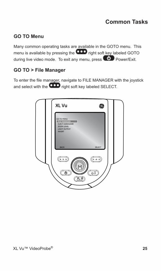
GO TO Menu
Many common operating tasks are available in the GOTO menu. This menu is available by pressing the right soft key labeled GOTO during live video mode. To exit any menu, press Power/Exit.
GO TO > File Manager
To enter the file manager, navigate to FILE MANAGER with the joystick and select with the right soft key labeled SELECT.
GO TO MENUFILE MANAGEREJECT HARDWAREZOOM LEVELLIGHT OUTPUTINVERT
BACK SELECT
XL Vu

Common Tasks
26 XL Vu™ VideoProbe®
GO TO > Eject Hardware
To eject USB thumb drives before removal, use the joystick to navigate to the right of EJECT HARDWARE and select USB1 using the right soft key labeled SELECT.
Note: Always use EJECT HARDWARE before removing a USB thumb drive to prevent loss of data.
BACK SELECT
GO TO MENUFILE MANAGEREJECT HARDWAREZOOM LEVELLIGHT OUTPUTINVERT
USB1
XL Vu

XL Vu™ VideoProbe® 27
Common Tasks
GO TO > Zoom Level
An image can be zoomed from 1 (normal view) to 3 (3 times zoomed). Navigate to the right of ZOOM LEVEL and use the joystick to adjust the zoom level.
BACK SELECT
GO TO MENUFILE MANAGEREJECT HARDWAREZOOM LEVELLIGHT OUTPUTINVERT
1 3
XL Vu

Common Tasks
28 XL Vu™ VideoProbe®
GO TO > Light Output
To turn the LED optical light On or Off, navigate to the right of LIGHT OUTPUT and select ON or OFF.
BACK SELECT
GO TO MENUFILE MANAGEREJECT HARDWAREZOOM LEVELLIGHT OUTPUTINVERT
ONOFF
XL Vu
Note: Turning on FREEZE FRAME is a convenient way to turn off the light output and is ideal for changing optical tips and conserving battery charge.
XL Vu™ VideoProbe® 29
Common Tasks
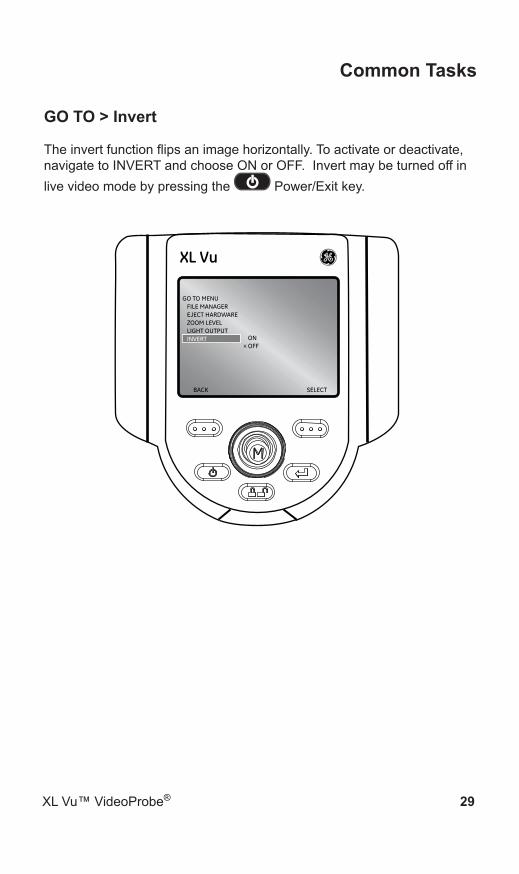
GO TO > Invert
The invert function flips an image horizontally. To activate or deactivate, navigate to INVERT and choose ON or OFF. Invert may be turned off in live video mode by pressing the Power/Exit key.
BACK SELECT
GO TO MENUFILE MANAGEREJECT HARDWAREZOOM LEVELLIGHT OUTPUTINVERT ON
OFF
XL Vu
Common Tasks
30 XL Vu™ VideoProbe®
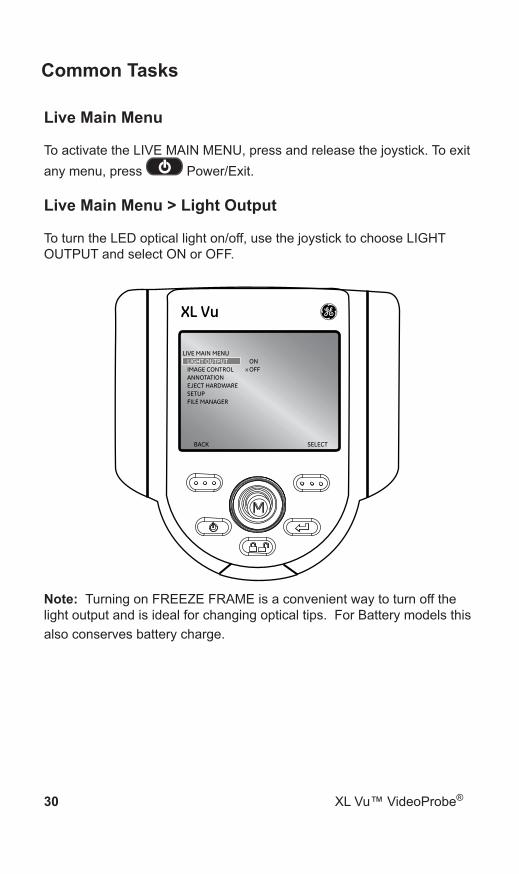
Live Main Menu
To activate the LIVE MAIN MENU, press and release the joystick. To exit any menu, press Power/Exit.
Live Main Menu > Light Output
To turn the LED optical light on/off, use the joystick to choose LIGHT OUTPUT and select ON or OFF.
BACK SELECT
LIVE MAIN MENULIGHT OUTPUTIMAGE CONTROLANNOTATIONEJECT HARDWARESETUPFILE MANAGER
ONOFF
XL Vu
Note: Turning on FREEZE FRAME is a convenient way to turn off the light output and is ideal for changing optical tips. For Battery models this also conserves battery charge.

XL Vu™ VideoProbe® 31
Common Tasks
Live Main Menu > Image Control
From the LIVE MAIN MENU, select IMAGE CONTROL. The changes made to the Image Controls take effect immediately.
BACK SELECT
LIVE MAIN MENULIGHT OUTPUTIMAGE CONTROLANNOTATIONEJECT HARDWARESETUPFILE MANAGER
XL Vu
The following options are then available:Image Brightness• Zoom Level• Invert•
Note: By pressing the power/exit key twice, any image control features will be turned off and returned to factory default settings.

Common Tasks
32 XL Vu™ VideoProbe®
Live Main Menu > Image Control > Image Brightness
Navigate to IMAGE BRIGHTNESS from the IMAGE CONTROL Menu and use the joystick to adjust the image brightness.
BACK SELECT
IMAGE CONTROLIMAGE BRIGHTNESSZOOM LEVELINVERT
0 100
XL Vu

XL Vu™ VideoProbe® 33
Common Tasks
Live Main Menu > Image Control > Zoom Level
Navigate to ZOOM LEVEL from the IMAGE CONTROL Menu and use the joystick to adjust the zoom level. Digital zoom levels from 1x to 3x may be selected.
BACK SELECT
IMAGE CONTROLIMAGE BRIGHTNESSZOOM LEVELINVERT 1 3
XL Vu

Common Tasks
34 XL Vu™ VideoProbe®
Live Main Menu > Image Control > Invert
The invert function flips an image horizontally. To activate or deactivate Invert, navigate to INVERT from the IMAGE CONTROL MENU and select ON or OFF.
BACK SELECT
IMAGE CONTROLIMAGE BRIGHTNESSZOOM LEVELINVERT ON
OFF
XL Vu
Note: This feature is most useful when using Sideview Optical Tips.

XL Vu™ VideoProbe® 35
Common Tasks
Live Main Menu > Annotation
Annotating an XL Vu image means adding text or arrows to describe or point out areas of interest: cracks, defects, etc. Annotation may be used on live, frozen, and recalled images.
To alter the annotation settings, press the joystick to activate the LIVE MAIN MENU and select ANNOTATION.
BACK SELECT
LIVE MAIN MENULIGHT OUTPUTIMAGE CONTROLANNOTATIONEJECT HARDWARESETUPFILE MANAGER
XL Vu
Note: There is a maximum of 3 lines of text/arrows per annotation.
Note: See the Freeze Frame Menu to enable Audio Annotation.

Common Tasks
36 XL Vu™ VideoProbe®
Live Main Menu > Annotation > Text
To add, edit, or clear text on a specific image, select TEXT from the ANNOTATION menu.
BACK SELECT
ANNOTATIONTEXTARROWPRESETHIDE ANNOTATION
ADDEDITCLEAR
XL Vu
CANCEL DONE
USE JOYSTICK/ENTER TO ENTER TEXT.
^ < > v ENTER SPACE BACKSPACEBO2,@
CP3:#
DQ4;$
ER5?%
FS6!&
GT7\_
HU8/|
IV9^(
JW0<)
KX+>{
LY-`}
MZ=‘[
*“]
AN1.~
XL Vu
Note: Maximum number of text annotations is 50.

XL Vu™ VideoProbe® 37
Common Tasks
Live Main Menu > Annotation > Arrow
To add, edit or clear arrow on a specific image, select ARROW from the ANNOTATION menu.
BACK SELECT
ANNOTATIONTEXTARROWPRESETHIDE ANNOTATION
ADDEDITCLEAR
XL Vu
Note: Maximum number of arrow annotations is 25.

Common Tasks
38 XL Vu™ VideoProbe®
Live Main Menu > Annotation > Preset
To create, recall or delete a preset annotation that will display throughout an inspection, choose PRESET from the ANNOTATION menu.
BACK SELECT
ANNOTATIONTEXTARROWPRESETHIDE ANNOTATION
CREATERECALLDELETE
XL Vu
Note: Maximum number of preset annotations is 100.

XL Vu™ VideoProbe® 39
Common Tasks
Live Main Menu > Annotation > Hide Annotation
To hide or unhide an annotation, select HIDE ANNOTATION from the ANNOTATION menu followed by ON or OFF.
BACK SELECT
ANNOTATIONTEXTARROWPRESETHIDE ANNOTATION ON
OFF
XL Vu

Common Tasks
40 XL Vu™ VideoProbe®
Live Main Menu > File Manager
To manage files and folders on the XL Vu VideoProbe system, select FILE MANAGER with the joystick. For more details refer to the FILE MANAGEMENT section in the Operation Chapter.
BACK SELECT
LIVE MAIN MENULIGHT OUTPUTIMAGE CONTROLANNOTATIONEJECT HARDWARESETUPFILE MANAGER
XL Vu

XL Vu™ VideoProbe® 41
Common Tasks
Live Main Menu > Eject Hardware To eject USB thumb drives before removal, use the joystick to navigate to the right of EJECT HARDWARE and select USB1 using the right soft key labeled SELECT.
BACK SELECT
LIVE MAIN MENULIGHT OUTPUTIMAGE CONTROLANNOTATIONEJECT HARDWARESETUPFILE MANAGER
x USB1
XL Vu
Note: Always use EJECT HARDWARE before removing a USB thumbdrive to prevent loss of data.

Common Tasks
42 XL Vu™ VideoProbe®
Live Main Menu > Setup
To change default settings, select SETUP. For more information see SYSTEM SETUP Section in the Operation Chapter.
BACK SELECT
LIVE MAIN MENULIGHT OUTPUTIMAGE CONTROLANNOTATIONEJECT HARDWARESETUPFILE MANAGER
XL Vu

Operation
XL Vu™ VideoProbe® 43
Live Main Menu > Setup
The System Setup Menu accesses the default settings. To exit any menu, press Power/Exit.
Live Main Menu > Setup > Screen/Display Setup To alter the display setup, press the joystick to activate the LIVE MAIN MENU. Select SETUP followed by SCREEN/DISPLAY.
BACK SELECT
LIVE MAIN MENULIGHT OUTPUTIMAGE CONTROLANNOTATIONEJECT HARDWARESETUPFILE MANAGER
XL Vu

44 XL Vu™ VideoProbe®
Operation
Live Main Menu > Setup > Screen/Display Setup > Battery Icon (Battery Version Only)
To enable and disable the battery icon, select BATTERY ICON followed by ON or OFF.
BACK SELECT
SCREEN/DISPLAYBATTERY ICONDATE/TIMELOGOTEXT COLORWHITE BALANCE
ONOFF
XL Vu

Operation
XL Vu™ VideoProbe® 45
Live Main Menu > Setup > Screen/Display Setup > Date / Time
To enable or disable the date/time stamp, as well as set the date and time, select DATE/TIME from the SCREEN/DISPLAY menu.
BACK SELECT
SCREEN/DISPLAYBATTERY ICONDATE/TIMELOGOTEXT COLORWHITE BALANCE
ONOFFSET
X
XL Vu
46 XL Vu™ VideoProbe®
Operation
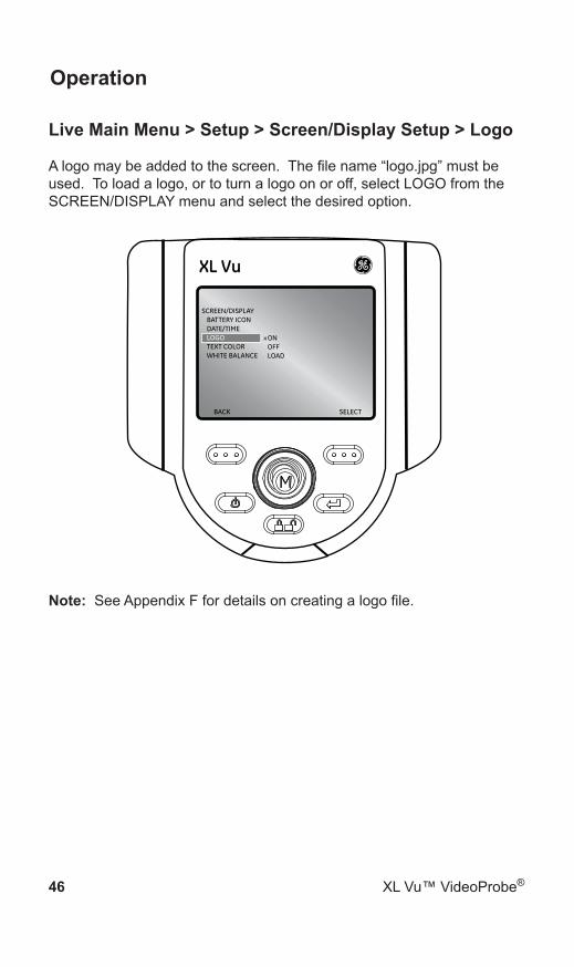
Live Main Menu > Setup > Screen/Display Setup > Logo
A logo may be added to the screen. The file name “logo.jpg” must be used. To load a logo, or to turn a logo on or off, select LOGO from the SCREEN/DISPLAY menu and select the desired option.
BACK SELECT
SCREEN/DISPLAYBATTERY ICONDATE/TIMELOGOTEXT COLORWHITE BALANCE
ONOFFLOAD
XL Vu
Note: See Appendix F for details on creating a logo file.
Operation
XL Vu™ VideoProbe® 47
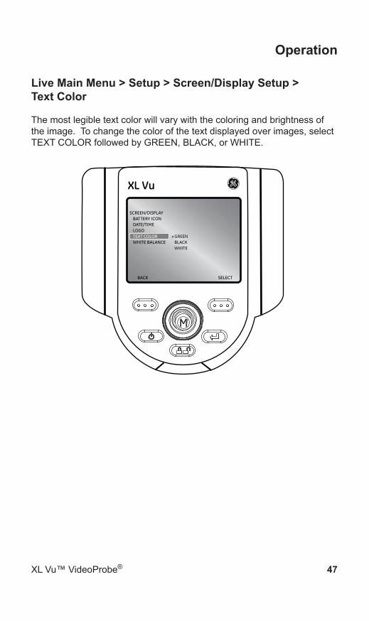
Live Main Menu > Setup > Screen/Display Setup > Text Color
The most legible text color will vary with the coloring and brightness of the image. To change the color of the text displayed over images, select TEXT COLOR followed by GREEN, BLACK, or WHITE.
BACK SELECT
SCREEN/DISPLAYBATTERY ICONDATE/TIMELOGOTEXT COLORWHITE BALANCE
GREENBLACKWHITE
XL Vu

48 XL Vu™ VideoProbe®
Operation
Live Main Menu > Setup > Screen/Display Setup >White Balance
White balance corrects color so white appears white despite any slight hues that may be present under varying lighting and ambient conditions.
To execute white balance, select WHITE BALANCE from the SCREEN/DISPLAY menu. Options are to set a custom white balance or use the default settings.
BACK SELECT
SCREEN/DISPLAYBATTERY ICONDATE/TIMELOGOTEXT COLORWHITE BALANCE EXECUTE
RESTORE DEFAULT
XL Vu

Operation
XL Vu™ VideoProbe® 49
Live Main Menu > Setup > Video Record Setup
To change video record defaults, press the joystick to activate the LIVE MAIN MENU. Select SETUP followed by VIDEO RECORD SETUP.
BACK SELECT
SETUPSCREEN/DISPLAYVIDEO RECORD SETUPSTILL IMAGE SETUPAUDIO ANNOTATION SETUPLANGUAGE SETUPSYSTEM TOOLS
XL Vu

50 XL Vu™ VideoProbe®
Operation
Live Main Menu > Setup > Video Record Setup > Save Location
Select SAVE LOCATION from the VIDEO RECORD SETUP menu and navigate to the desired location.
BACK SELECT
VIDEO RECORD SETUPSAVE LOCATIONMPEG QUALITY
XL Vu

Operation
XL Vu™ VideoProbe® 51
Live Main Menu > Setup > Video Record Setup > MPEG Quality
To set the video quality, select MPEG QUALITY from the VIDEO RECORD SETUP menu followed by LOW or HIGH.
BACK SELECT
VIDEO RECORD SETUPSAVE LOCATIONMPEG QUALITY LOW
HIGH
XL Vu

52 XL Vu™ VideoProbe®
Operation
Live Main Menu > Setup > Still Image Setup To change still image defaults, press the joystick to activate the LIVE MAIN MENU. Select SETUP followed by STILL IMAGE SETUP.
BACK SELECT
SETUPSCREEN/DISPLAYVIDEO RECORD SETUPSTILL IMAGE SETUPAUDIO ANNOTATION SETUPLANGUAGE SETUPSYSTEM TOOLS
XL Vu

Operation
XL Vu™ VideoProbe® 53
Live Main Menu > Setup > Still Image Setup > Save Location
Select SAVE LOCATION from the STILL IMAGE SETUP menu and use the joystick to navigate to the desired location.
BACK SELECT
STILL IMAGE SETUPSAVE LOCATIONFORMATJPEG QUALITY
XL Vu

54 XL Vu™ VideoProbe®
Operation
Live Main Menu > Setup > Still Image Setup > Format
To choose the image format [Bitmap (BMP) or JPEG (JPG)], navigate to the right of FORMAT and select BMP or JPG.
BACK SELECT
STILL IMAGE SETUPSAVE LOCATIONFORMATJPEG QUALITY
BMPJPG
XL Vu

Operation
XL Vu™ VideoProbe® 55
Live Main Menu > Setup > Still Image Setup > JPEG Quality
To choose JPEG quality, the user must first select JPEG image format. Once selected, navigate to the right of JPEG QUALITY and select LOW or HIGH.
BACK SELECT
STILL IMAGE SETUPSAVE LOCATIONFORMATJPEG QUALITY LOW
HIGH
XL Vu

56 XL Vu™ VideoProbe®
Operation
Live Main Menu > Setup > Audio Annotation Setup
To change audio defaults, press the joystick to activate the LIVE MAIN MENU. Select Setup followed by AUDIO ANNOTATION SETUP.
BACK SELECT
SETUPSCREEN/DISPLAYVIDEO RECORD SETUPSTILL IMAGE SETUPAUDIO ANNOTATION SETUPLANGUAGE SETUPSYSTEM TOOLS
XL Vu
Note: To access AUDIO ANNOTATION, press the Joystick from a frozen image. Select ANNOTATION followed by AUDIO. The following options will be available:
RECORD• PLAY• DELETE•

Operation
XL Vu™ VideoProbe® 57
Live Main Menu > Setup > Audio Annotation Setup > Playback Volume
To set the playback volume, select PLAYBACK VOLUME from the AUDIO ANNOTATION SETUP menu. Use the joystick to control the volume from 0 to 10.
BACK SELECT
AUDIO ANNOTATION SETUPPLAYBACK VOLUME
0 10
XL Vu

58 XL Vu™ VideoProbe®
Operation
Live Main Menu > Setup > Language Setup
To load or change the system language, select LANGUAGE SETUP from the SETUP menu followed by the appropriate language.
BACK SELECT
SETUPSCREEN/DISPLAYVIDEO RECORD SETUPSTILL IMAGE SETUPAUDIO SETUPLANGUAGE SETUPSYSTEM TOOLS
XL Vu
The following options are available: LOAD• CHANGE•

Operation
XL Vu™ VideoProbe® 59
Live Main Menu > Setup > System Tools
To view system information or adjust power management, select SETUP from the LIVE MAIN MENU followed by SYSTEM TOOLS.
BACK SELECT
SETUPSCREEN/DISPLAYVIDEO RECORD SETUPSTILL IMAGE SETUPAUDIO SETUPLANGUAGE SETUPSYSTEM TOOLS
XL Vu
60 XL Vu™ VideoProbe®
Operation
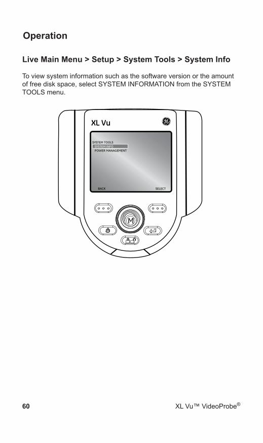
Live Main Menu > Setup > System Tools > System Info
To view system information such as the software version or the amount of free disk space, select SYSTEM INFORMATION from the SYSTEM TOOLS menu.
BACK SELECT
SYSTEM TOOLSSYSTEM INFOPOWER MANAGEMENT
XL Vu

Operation
XL Vu™ VideoProbe® 61
Capturing Images and Video
Steering the VideoProbe
The joystick controls articulation (steering) of the probe tip. When viewing a live video image, move the joystick towards the desired inspection area.
Articulation Lock
To hold the bending neck in place while steering, press and release the Steering Control key. A lock icon will appear in the corner of the
display to symbolize steer and stay is enabled. The probe will now stay in place when the joystick is released.To unlock steering, press and release Steering Control again. The
lock icon will disappear.
RECORD GOTO
XL Vu

62 XL Vu™ VideoProbe®
Operation
Articulation Home
Press and hold to engage HOME function to straighten bending neck. A blinking home icon will appear on LCD when enabled.
HOME icon will disappear when system is finished.
RECORD GOTO
XL Vu
Operation
XL Vu™ VideoProbe® 63
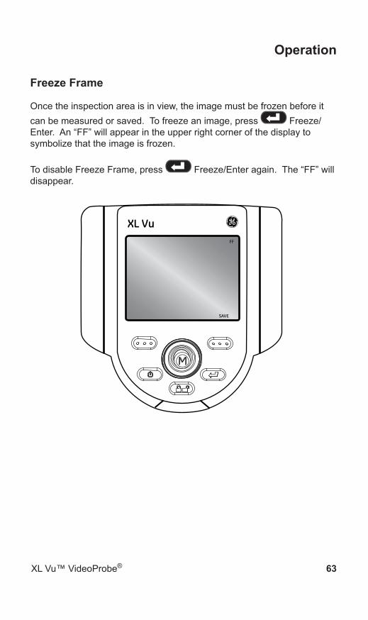
Freeze Frame
Once the inspection area is in view, the image must be frozen before it can be measured or saved. To freeze an image, press Freeze/Enter. An “FF” will appear in the upper right corner of the display to symbolize that the image is frozen.
To disable Freeze Frame, press Freeze/Enter again. The “FF” will disappear.
SAVE
XL VuFF

64 XL Vu™ VideoProbe®
Operation
Freeze Frame Menu
Once Freeze Frame is enabled, press the joystick to enter the FREEZE FRAME MENU.
BACK SELECT
FREEZE FRAME MENUSAVE ASANNOTATION
XL Vu
The following options are available:SAVE AS• ANNOTATION•
Operation
XL Vu™ VideoProbe® 65
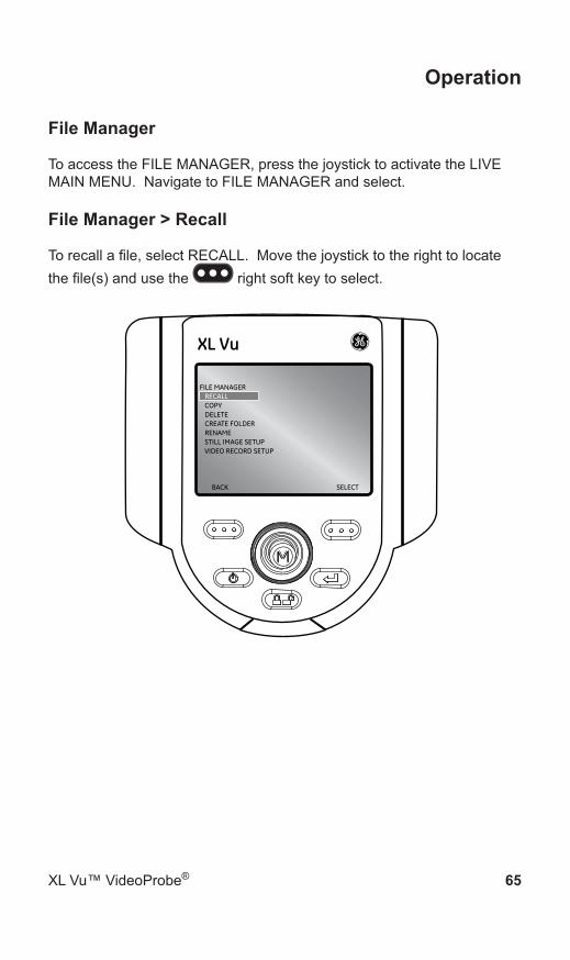
File Manager
To access the FILE MANAGER, press the joystick to activate the LIVE MAIN MENU. Navigate to FILE MANAGER and select.
File Manager > Recall
To recall a file, select RECALL. Move the joystick to the right to locate the file(s) and use the right soft key to select.
BACK SELECT
FILE MANAGERRECALLCOPYDELETECREATE FOLDERRENAMESTILL IMAGE SETUPVIDEO RECORD SETUP
XL Vu

66 XL Vu™ VideoProbe®
Operation
Recalled Image Menu
After recalling an image, press the joystick to activate the RECALLED IMAGE MENU.
BACK SELECT
RECALLED IMAGE MENUSAVE ASANNOTATION
XL Vu
The following options are available: SAVE AS• ANNOTATION•
Operation
XL Vu™ VideoProbe® 67
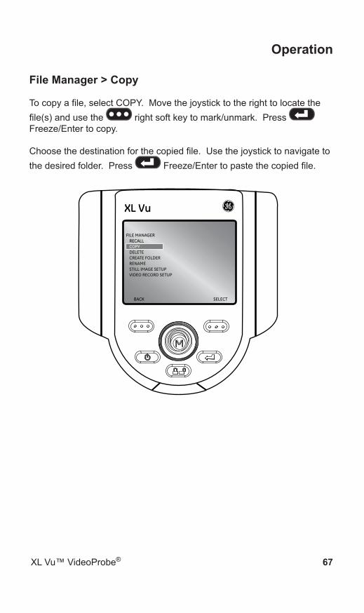
File Manager > Copy
To copy a file, select COPY. Move the joystick to the right to locate the file(s) and use the right soft key to mark/unmark. Press Freeze/Enter to copy.
Choose the destination for the copied file. Use the joystick to navigate to the desired folder. Press Freeze/Enter to paste the copied file.
BACK SELECT
FILE MANAGERRECALLCOPYDELETECREATE FOLDERRENAMESTILL IMAGE SETUPVIDEO RECORD SETUP
XL Vu

68 XL Vu™ VideoProbe®
Operation
File Manager > Delete
To delete a file, select DELETE FILE. Move the joystick to the right to locate the file(s) and select. Press Freeze/Enter to delete.
BACK SELECT
FILE MANAGERRECALLCOPYDELETECREATE FOLDERRENAMESTILL IMAGE SETUPVIDEO RECORD SETUP
XL Vu

Operation
XL Vu™ VideoProbe® 69
File Manager > Create Folder
To create a folder, select CREATE FOLDER. Select the location of the folder. Use the joystick to highlight and Freeze/Enter to select each letter. When done, press the right soft key to save the folder name.
BACK SELECT
FILE MANAGERRECALLCOPYDELETECREATE FOLDERRENAMESTILL IMAGE SETUPVIDEO RECORD SETUP
XL Vu
70 XL Vu™ VideoProbe®
Operation
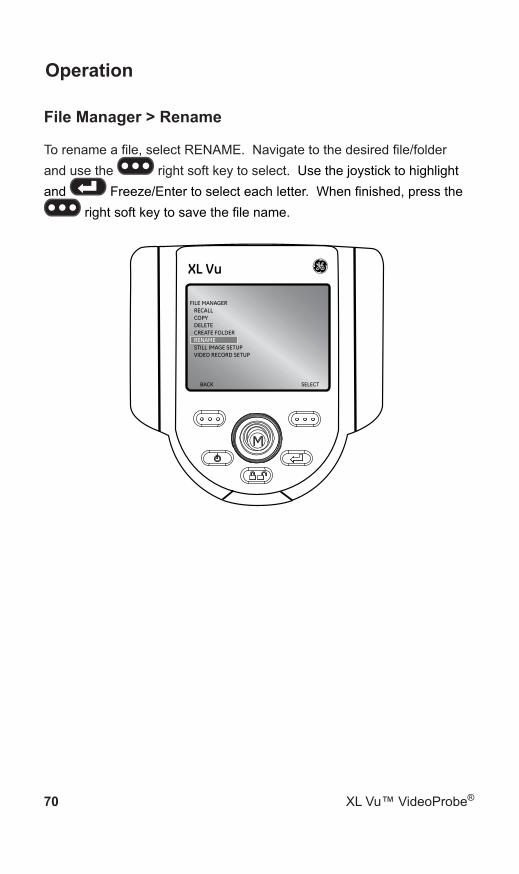
File Manager > Rename
To rename a file, select RENAME. Navigate to the desired file/folder and use the right soft key to select. Use the joystick to highlight and Freeze/Enter to select each letter. When finished, press the
right soft key to save the file name.
BACK SELECT
FILE MANAGERRECALLCOPYDELETECREATE FOLDERRENAMESTILL IMAGE SETUPVIDEO RECORD SETUP
XL Vu

Operation
XL Vu™ VideoProbe® 71
File Manager > Still Image Setup
To save/capture a still image if freeze frame is enabled, press the right soft key with SAVE on the LCD above to save to the default
location. Alternately, press and hold Freeze/Enter to auto-save.
File Manager > Video Record Setup
To record live video, press the left soft key labeled RECORD on the LCD above. A record symbol will appear in the upper right hand corner. When the video is stopped, it will automatically save to the default location.
To view recorded videos, use either QuickTime or VLC software. Both are included with the system, located on the documentation CD.
72 XL Vu™ VideoProbe®
Operation
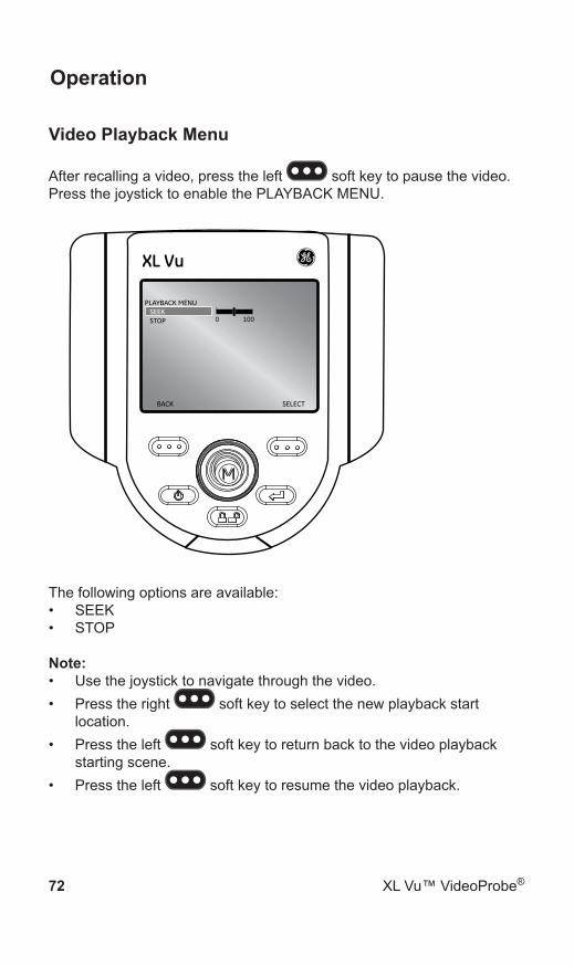
Video Playback Menu
After recalling a video, press the left soft key to pause the video. Press the joystick to enable the PLAYBACK MENU.
BACK SELECT
PLAYBACK MENUSEEKSTOP 0 100
XL Vu
The following options are available:SEEK• STOP•
Note:Use the joystick to navigate through the video.• Press the right • soft key to select the new playback start location.Press the left • soft key to return back to the video playback starting scene.Press the left • soft key to resume the video playback.
XL Vu™ VideoProbe® 73
Maintenance
Inspecting and Cleaning the SystemInspect and clean the XL Vu system before and after each use with a soft cloth and a 70% alcohol-to-water solution. If using the system in a dirty environment, clean the components more frequently, as needed.
If damage is found, contact GE Sensing and Inspection Technologies for return instructions and an RMA (return material authorization) number. Early detection of minor conditions can prevent costly repair.
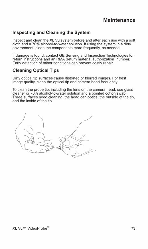
Cleaning Optical TipsDirty optical tip surfaces cause distorted or blurred images. For best image quality, clean the optical tip and camera head frequently.
To clean the probe tip, including the lens on the camera head, use glass cleaner or 70% alcohol-to-water solution and a pointed cotton swab. Three surfaces need cleaning: the head can optics, the outside of the tip, and the inside of the tip.

74 XL Vu™ VideoProbe®
Maintenance
Sales and Technical SupportUSA 1 888 332 3848 (toll free in USA only)
1 315 554 2000 (Phone) 1 866 899 4184 (Fax)
Canada 877 895 5665780 430 9060
France +33 2 28 23 08 00
Germany +49 7471 98820
Hong Kong +852 2877 0801
Italy +39 39 65 1341
Japan +81 422 67 7067
United Kingdom +44 1993 822613
Web Sitewww.geinspectiontechnologies.com

XL Vu™ VideoProbe® 75
Maintenance
ServiceTo obtain service for a VideoProbe system, please contact one of the service centers below. If the problem cannot be corrected over the phone, a Return Materials Authorization number (RMA) will be given along with instructions for shipment to an authorized service center.
Always contact an authorized GE Inspection Technologies service center for an RMA prior to returning a product for service and/or repair.
USA GE Inspection Technologies 721 Visions DriveSkaneateles, NY 13152Phone: 1 888 335 3848 (toll-free in USA only) 1 315 554 2000Fax: 1 866 899 4184
Germany GE Inspection Technologies GmbHLotzenacker 472379 HechingenPhone: +49 7471 98820Fax: +49 7471 7882 30
Hong KongGE Inspection Technologies (HK) Ltd.Unit 1602, 16/F Sing Pao Building101 Kings RoadNorth PointHong KongPhone: +852 2877 0801Fax: +852 2877 0868

76 XL Vu™ VideoProbe®
Technical Specifications
Technical Specifications:Operating Temperature
Tip -25ºC to 80ºC (-13ºF to to 176oF)Reduced articulation below 0oC(32oF)
System -20o to 46o C (-4oF to 115oF) LCD requires warm-up period below 0oC (32oF)
Storage Temperature -25o to 60o C (-13oF to 140oF)Relative Humidity 95% max, non-condensingWaterproof Insertion tube and tip to 14.7 psi (1
bar, 10.2m of H2O, 33.5 ft of H2O) Hazardous Environments Not rated for use in hazardous
environments.Camera
Diameter Probe 6.1 mm (0.24”) Image Sensor 1/6” Color SUPER HAD™ CCD
camera Pixel Count 440,000 pixels Housing Titanium
Diameter Probe 3.9 mm (0.15”) Image Sensor 1/10” Color SUPER HAD™ CCD
camera Pixel Count 290,000 pixels Housing Titanium
System System Dimensions 9.5 x 13.3 x 34.3 cm (3.8 x 5.3 x 13.5”)Case Dimensions 62.5 x 21.8 x 50.0 cm (24.6 x 8.6 x
19.7”)System Weight Battery XL Vu:
In Case - 8.23 kg (18.15 lbs)Out of Case - 1.77 kg (3.90 lbs)Corded XL Vu:In Case - 8.63 kg (19.02 lbs)Out of Case - 2.16 kg (4.77 lbs)

XL Vu™ VideoProbe® 77
Technical Specifications
Construction Polycarbonate housing with integrated VersalonTM bumpers
LCD Monitor Integratged 9.4 cm (3.7”) active matrix VGA color LCD
Joystick Control 360º All-Way® tip articulation, menu access, and navigation
Button Set Access user functions, measurement, and digital functions
Audio Integrated 2.5mm headset / microphone jack
Internal Memory 1GB flash memoryData I/O ports 1 USB 2.0 port
VGA Video OutBrightness Control Auto and VariableIllumination Type White LEDWhite Balance Factory default or user defined
PowerLithium Ion Battery 8.4 V
38 Wh (2-hour) or 75 Wh (4-hour)
Power SupplyCorded XL Vu AC Input: 90-264 Vac 47-63 Hz
<.75 A rms @ 115 Vac DC Output: 9V +/-5%, 3.4A
Battery XL Vu AC Input: 90-264 Vac, 47-63Hz, <1.2Arms @ 90 VacDC Output: 10.2V +5/-3%. 4.9A
Standards Compliance and ClassificationsStandards Compliance Group 1, Class A: EN61326-1(Basic
radiated immunity), UL, IEC, EN CSA-C22.2:61010-1, UN/DOT T1-T8
78 XL Vu™ VideoProbe®
Technical Specifications
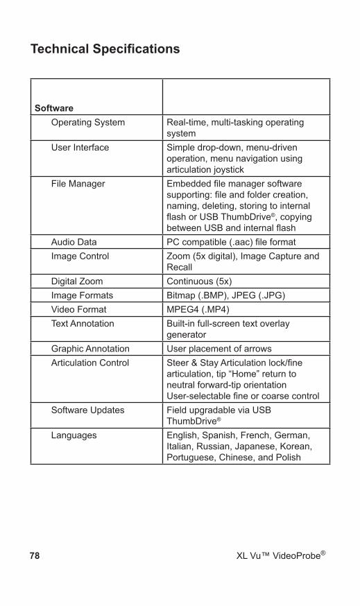
SoftwareOperating System Real-time, multi-tasking operating
systemUser Interface Simple drop-down, menu-driven
operation, menu navigation using articulation joystick
File Manager Embedded file manager software supporting: file and folder creation, naming, deleting, storing to internal flash or USB ThumbDrive®, copying between USB and internal flash
Audio Data PC compatible (.aac) file formatImage Control Zoom (5x digital), Image Capture and
RecallDigital Zoom Continuous (5x)Image Formats Bitmap (.BMP), JPEG (.JPG)Video Format MPEG4 (.MP4)Text Annotation Built-in full-screen text overlay
generatorGraphic Annotation User placement of arrowsArticulation Control Steer & Stay Articulation lock/fine
articulation, tip “Home” return to neutral forward-tip orientation User-selectable fine or coarse control
Software Updates Field upgradable via USB ThumbDrive®
Languages English, Spanish, French, German, Italian, Russian, Japanese, Korean, Portuguese, Chinese, and Polish
XL Vu™ VideoProbe® 79
Technical Specifications
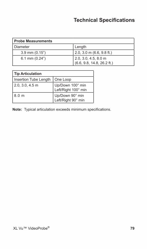
Probe MeasurementsDiameter Length
3.9 mm (0.15”) 2.0, 3.0 m (6.6, 9.8 ft.)6.1 mm (0.24”) 2.0, 3.0, 4.5, 8.0 m
(6.6, 9.8, 14.8, 26.2 ft.)
Tip ArticulationInsertion Tube Length One Loop2.0, 3.0, 4.5 m Up/Down 100° min
Left/Right 100° min8.0 m Up/Down 90° min
Left/Right 90° min
Note: Typical articulation exceeds minimum specifications.

80 XL Vu™ VideoProbe®
Appendix
Optical Tip TableA.
Tip Diameter (mm)
View (DOV)
Color Field of View (FOV)
Depth of Field (DOF)
Part Number
Standard Optical Tips
3.9 Forward None 80 6-80mm.24-3.15”
PXT480FG
3.9 Side Brown 80 4-80mm.16-3.15”
PXT480SG
3.9 Forward Yellow 90 3-40mm.12-1.57”
PXT490FN
3.9 Side Red 90 2-16mm.08-.63”
PXT490SN
6.1 Forward None 50 50mm-infinity1.97” - infinity
XLG3T6150FF
6.1 Forward White 50 12-200mm.47-7.87”
XLG3T6150FG
6.1 Forward Black 120 5-120mm.20-4.72”
XLG3T61120FG
6.1 Forward Orange 80 3-20mm.12-.79”
XLG3T6180FN
6.1 Forward Yellow 90 20mm-infinity.79”-infinity
XLG3T6190FF
6.1 Forward Oblique
Purple 50 12-80mm.5-3.2”
XLG3T6150FB
6.1 Side Brown 50 45mm-infinity1.77”-infinity
XLG3T6150SF
6.1 Side Green 50 9-160mm.35-6.30”
XLG3T6150SG
6.1 Side Blue 120 4-100mm.16-3.94”
XLG3T61120SG

XL Vu™ VideoProbe® 81
Appendix
6.1 Side Red 80 1-20mm.04-.79”
XLG3T6180SN
6.1 Side Green 50 9-160mm.35-6.30”
XLG3T6150SG
6.1 Side Brown 50 45mm1.77”-infinity
XLG3T6150SF

82 XL Vu™ VideoProbe®
Appendix
Chemical CompatibilityB.
Chemical compatibility refers to the probe’s ability to come into contact with various liquid substances and not be damaged.
WARNING Do not use this system in explosive environments.
These substances are safe for a short duration of contact with the insertion tube:
Water• Aircraft Gasoline• Jet-A-Fuel• Isopropyl alcohol• JP-4 Fuel• Kerosene• Synthetic Turbo Oil• Gasoline• Diesel Fuel• Hydraulic Oil• Inhibited Transformer Oil•
Subsequent to contact with the above fluids, the insertion tube must be cleaned prior to storage.
WarrantyC.
GE Inspection Technologies warrants its VideoProbe components, when new, to be free from defects in material and workmanship and to perform in accordance with manufacturer’s specifications under normal use and service for a period of one year from the date of purchase from GE Inspection Technologies or its authorized distributors, except that, the light source is warranted for a period of 3 years from the date of purchase, the battery is warranted for a period of 30 days from the date of purchase, and where used, servo motors in the articulation drive system are warranted for the life of this VideoProbe product.
GE Inspection Technologies’ obligation under this warranty is limited to the repair or replacement of components determined by GE Inspection Technologies to be defective within the warranty period at no cost to the original purchaser, except for return shipping expenses. It shall be the purchaser’s responsibility to return the product to GE Inspection Technologies or one of its authorized service centers. The warranty does

XL Vu™ VideoProbe® 83
Appendix
not cover accessories or optional equipment not manufactured by GE Inspection Technologies, but these items may be covered by separate manufacturers’ warranties.
This warranty extends to the original purchaser and cannot be assigned or transferred to any third party. This warranty shall not apply to any damage or product failure determined by GE Inspection Technologies to have been caused by misuse, accident (including shipping damage), neglect, improper maintenance, modification or repair by someone other than GE Inspection Technologies or one of its authorized service representatives.
These express warranties are in lieu of any other warranties, express or implied, including the warranties of merchantability and fitness for a particular purpose, and no other person has been authorized to assume for GE Inspection Technologies any other liability in connection with the sale of its VideoProbe products. GE Inspection Technologies shall not be liable for any loss or damages, whether direct or indirect, incidental, or consequential, resulting from the breach of any express warranty set forth herein.
Environmental Compliance D.
The equipment purchased has required the extraction and use of natural resources for its production. It may contain hazardous substances that could impact health and the environment.
In order to avoid the dissemination of those substances in the environment and to diminish the pressure on the natural resources, we encourage the use of appropriate take-back systems. Those systems will reuse or recycle most of the materials of end-life equipment in a sound way.
The cross-out wheeled bin symbol encourages the use of those systems.
If more information is needed on the collection, reuse, and recycling systems, please contact the appropriate local or regional waste administration.

84 XL Vu™ VideoProbe®
Appendix
This product contains a battery that cannot be disposed of as unsorted municipal waste in the European Union. See the product documentation for specific battery information. The battery is marked with this symbol, which may include lettering to indicate cadmium (Cd), lead (Pb), or mercury (Hg). For proper recycling return the battery to your supplier or to a designated collection point.
What do the markings mean?Batteries and accumulators must be marked (either on the battery or accumulator or on its packaging, depending on size) with the separate collection symbol. In addition, the marking must include the chemical symbols of specific levels of toxic metals as follows:Cadmium (Cd) over 0.002%Lead (Pb) over 0.004%Mercury (Hg) over 0.0005%
The risks and your role in reducing themYour participation is an important part of the effort to minimize the impact of batteries and accumulators on the environment and on human health. For proper recycling you can return this product or the batteries or accumulators it contains to your supplier or to a designated collection point. Some batteries or accumulators contain toxic metals that pose serious risks to human health and to the environment. When required, the product marking includes chemical symbols that indicate the presence toxic metals: Pb for lead, Hg for mercury, and Cd for cadmium. Cadmium poisoning can result in cancer of the lungs and prostate gland. Chronic effects include kidney damage, pulmonary emphysema, and bone diseases such as osteomalcia and osteoporosis. Cadmium may also cause anemia, discoloration of the teeth, and loss of smell (anosmia). Lead is poisonous in all forms. It accumulates in the body, so each exposure is significant. Ingestion and inhalation of lead can cause severe damage to human health. Risks include brain damage, convulsions, malnutrition, and sterility. Mercury creates hazardous vapors at room temperature. Exposure to high concentrations of mercury vapor can cause a variety of severe symptoms. Risks include chronic inflammation of mouth and gums, personality change, nervousness, fever, and rashes.
Visit www.geinspectiontechnologies.com for take-back instructions and more information about this initiative.
Agency CertificationsE.
European Equipment Classification
Group 1, Class A
The mark on this product indicates it has been tested to and conforms

XL Vu™ VideoProbe® 85
Appendix
with the provisions noted within the 2004/108/EC Electromagnetic Compatibility Directive. The XL Vu system is in conformance with the following standard: EN61326-1(Basic radiated immunity).
Declarations of Conformity are held by GE Inspection Technologies GmbH:
GE Sensing & Inspection Technologies GmbH Product Service Center Lotzenäcker 472379 Hechingen GermanyTel: +49(0) 74719882 0 Fax: +49(0) 74719882 16
Safety Mark
The XL Vu system is in compliance with the following standards: UL 61010-1, IEC 61010-1, EN 61010-1 and CSA-C22.2 No. 61010-1.
Additional Certification Testing
UN / DOT T1-T8
Canadian Notice
This equipment does not exceed the Class A limits for radio noise emissions as described in the Radio Interference Regulations of the Canadian Department of Communications.
Le present appareil numerique n’emet pas de bruits radioelectriques depassant les limites applicables aux appareils numeriques de la classe A prescrites dans le Reglement sur le brouillage radioelectrique edicte par le ministere des Communications du Canada.

86 XL Vu™ VideoProbe®
Appendix
Creating a Personalized Logo FileF.
The XL Vu allows users to display a personalized logo on-screen or store with captured images. Typically, this file will be a corporate logo.
LOGO File Requirements
200 x 200 pixels maximum size• 24 Color• File name must be logo.jpg• File must be Microsoft• ® Windows® compatible
Creating the Logo File
Open logo file with image editor. 1. Create custom background comprised of Red 255, Green 0, 2. Blue 255. This will create a magenta-colored background that will appear transparent when loaded on the XL Vu.Save this file as a .png. 3. Close image editor.4. Locate the saved file, right click, choose rename. Rename file 5. from logo.png to logo.jpg. This will allow it to be recognized by the XL Vu.Transfer file to the USB ThumbDrive provided with system.6. Insert ThumbDrive into USB port on the XL Vu.7. Press joystick to enter Live Main Menu 8. Navigate to SETUP > SCREEN/DISPLAY > LOGO 9. Select LOAD10. Prompt will display “LOGO COPY COMPLETE”11.

©2009 General Electric Company. All rights reserved. Specifications subject to change without notice.
QuickTime and the QuickTime logo are trademarks or registered trademarks of Apple Computer, Inc., used under licence therefrom.
©2008 VideoLAN
Customer Support Centers
North/South America
721 Visions DriveSkaneateles, NY 13152Tel: 888-332-3848 315-554-2000 ext. 1
Europe
Lotzenäcker 472379 HechingenGermanyTel: +49 (0) 7471 9882 0
Asia/Pacific
Unit 1602, 16/F Sing Pao Building101 King’s RoadNorth PointHong KongTel: +852 2877 0801
E-mail: [email protected]
XLVUAMAN Rev. B Printed in USA
www.geinspectiontechnologies.com/en
Assembled in USA by GE Inspection Technologies