Embed Size (px)
Citation preview
334644CENr
Instructions - Parts
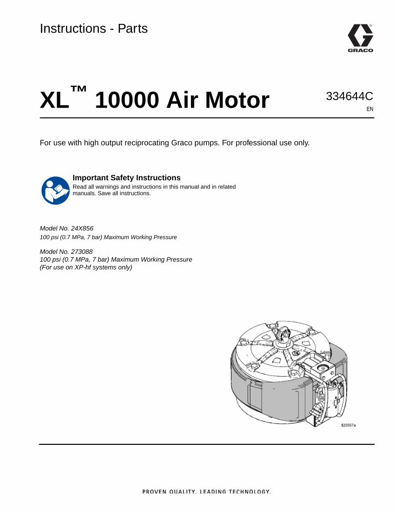
XL™ 10000 Air Moto
For use with high output reciprocating Graco pumps. For professional use only.Model No. 24X856100 psi (0.7 MPa, 7 bar) Maximum Working Pressure
Model No. 273088100 psi (0.7 MPa, 7 bar) Maximum Working Pressure(For use on XP-hf systems only)
Important Safety InstructionsRead all warnings and instructions in this manual and in related manuals. Save all instructions.
ContentsRelated Manuals . . . . . . . . . . . . . . . . . . . . . . . . . . . . 2Warnings . . . . . . . . . . . . . . . . . . . . . . . . . . . . . . . . . 3Component Identification . . . . . . . . . . . . . . . . . . . . 6General Information . . . . . . . . . . . . . . . . . . . . . . . . 7
Application . . . . . . . . . . . . . . . . . . . . . . . . . . . . . 7Reciprocating Signal Poppets . . . . . . . . . . . . . . . 7External Pilot Lines . . . . . . . . . . . . . . . . . . . . . . . 7Manual Override Buttons . . . . . . . . . . . . . . . . . . 7Low Pressure Operation . . . . . . . . . . . . . . . . . . . 7Performance . . . . . . . . . . . . . . . . . . . . . . . . . . . . 7Minimum Icing . . . . . . . . . . . . . . . . . . . . . . . . . . . 7Bleed Air . . . . . . . . . . . . . . . . . . . . . . . . . . . . . . . 7Extended Capabilities . . . . . . . . . . . . . . . . . . . . . 7
Grounding . . . . . . . . . . . . . . . . . . . . . . . . . . . . . . . . 8Motor Lubrication . . . . . . . . . . . . . . . . . . . . . . . . 8
Accessories . . . . . . . . . . . . . . . . . . . . . . . . . . . . . . . 8Bleed-type master air valve . . . . . . . . . . . . . . . . . 8Air Regulator . . . . . . . . . . . . . . . . . . . . . . . . . . . . 8Air Filter . . . . . . . . . . . . . . . . . . . . . . . . . . . . . . . . 8
Run Motor Manually . . . . . . . . . . . . . . . . . . . . . . . . . 9Troubleshooting . . . . . . . . . . . . . . . . . . . . . . . . . . . 10
Ice In Air Motor . . . . . . . . . . . . . . . . . . . . . . . . . 11Repair . . . . . . . . . . . . . . . . . . . . . . . . . . . . . . . . . . . 12
Preventive Maintenance Schedule . . . . . . . . . . 12Pressure Relief Procedure . . . . . . . . . . . . . . . . 12Repair Air Valve . . . . . . . . . . . . . . . . . . . . . . . . . 13Replace Pilot Valves . . . . . . . . . . . . . . . . . . . . . 16Repair Air Motor . . . . . . . . . . . . . . . . . . . . . . . . . 16
Parts . . . . . . . . . . . . . . . . . . . . . . . . . . . . . . . . . . . . 19Air Valve Parts . . . . . . . . . . . . . . . . . . . . . . . . . . 21Kits and Accessories . . . . . . . . . . . . . . . . . . . . . 22
Dimensions (Model No. 24X856) . . . . . . . . . . . . . . 24Mounting Hole Diagram . . . . . . . . . . . . . . . . . . . 24
Dimensions (Model No. 273088) . . . . . . . . . . . . . . 25Mounting Hole Diagram . . . . . . . . . . . . . . . . . . . 25
Technical Specifications . . . . . . . . . . . . . . . . . . . . 25Graco Standard Warranty . . . . . . . . . . . . . . . . . . . 26Graco Information . . . . . . . . . . . . . . . . . . . . . . . . . 26
Related ManualsManual Description
311762 Xtreme Lowers, Instructions-Parts
311825 Dura-Flo™ Lowers, Instructions-Parts
334645 Xtreme XL Packages, Instructions-Parts
3A4381 XP-hf Proportioner, Operation, Repair, Parts
2 334644C
Warnings
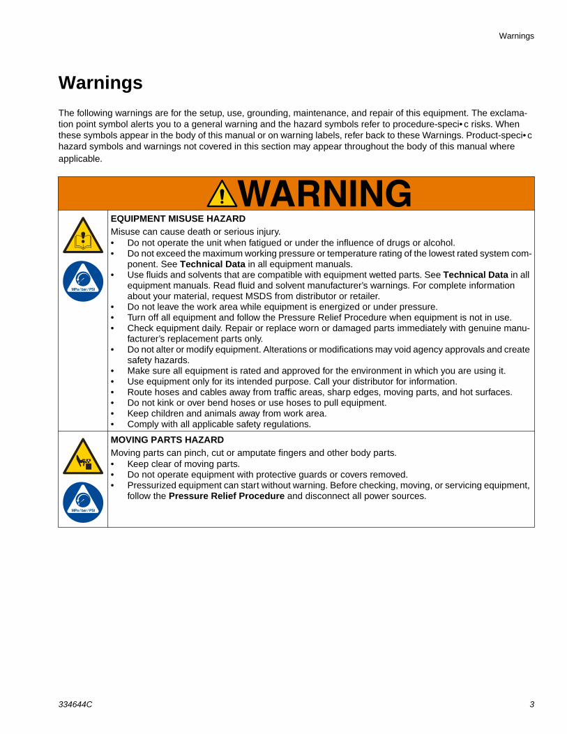
WarningsThe following warnings are for the setup, use, grounding, maintenance, and repair of this equipment. The exclama-tion point symbol alerts you to a general warning and the hazard symbols refer to procedure-speci• c risks. When these symbols appear in the body of this manual or on warning labels, refer back to these Warnings. Product-speci• c hazard symbols and warnings not covered in this section may appear throughout the body of this manual where applicable.
EQUIPMENT MISUSE HAZARDMisuse can cause death or serious injury.• Do not operate the unit when fatigued or under the influence of drugs or alcohol.• Do not exceed the maximum working pressure or temperature rating of the lowest rated system com-
ponent. See Technical Data in all equipment manuals.• Use fluids and solvents that are compatible with equipment wetted parts. See Technical Data in all
equipment manuals. Read fluid and solvent manufacturer’s warnings. For complete information about your material, request MSDS from distributor or retailer.
• Do not leave the work area while equipment is energized or under pressure.• Turn off all equipment and follow the Pressure Relief Procedure when equipment is not in use.• Check equipment daily. Repair or replace worn or damaged parts immediately with genuine manu-
facturer’s replacement parts only.• Do not alter or modify equipment. Alterations or modifications may void agency approvals and create
safety hazards.• Make sure all equipment is rated and approved for the environment in which you are using it.• Use equipment only for its intended purpose. Call your distributor for information.• Route hoses and cables away from traffic areas, sharp edges, moving parts, and hot surfaces.• Do not kink or over bend hoses or use hoses to pull equipment.• Keep children and animals away from work area.• Comply with all applicable safety regulations.
MOVING PARTS HAZARDMoving parts can pinch, cut or amputate fingers and other body parts.• Keep clear of moving parts.• Do not operate equipment with protective guards or covers removed.• Pressurized equipment can start without warning. Before checking, moving, or servicing equipment,
follow the Pressure Relief Procedure and disconnect all power sources.
334644C 3
Warnings
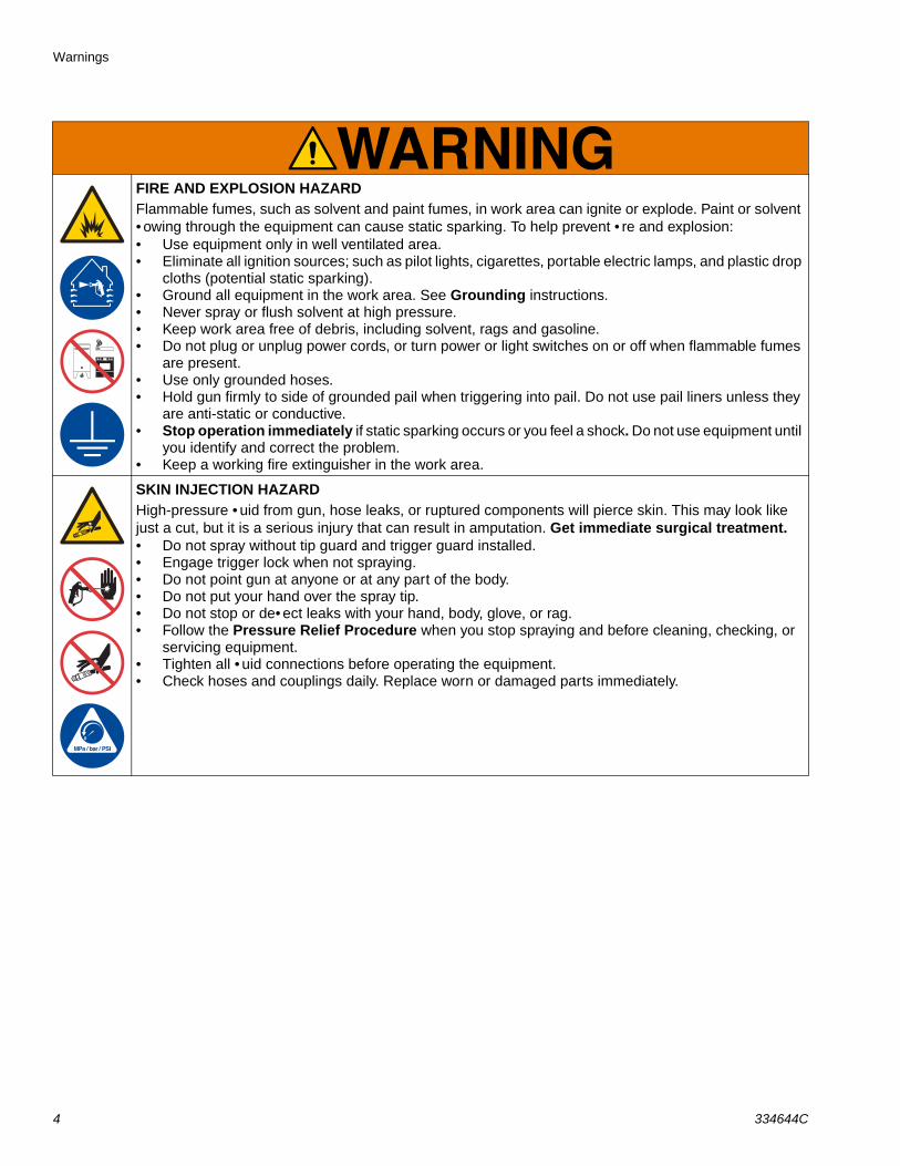
FIRE AND EXPLOSION HAZARDFlammable fumes, such as solvent and paint fumes, in work area can ignite or explode. Paint or solvent • owing through the equipment can cause static sparking. To help prevent • re and explosion:• Use equipment only in well ventilated area.• Eliminate all ignition sources; such as pilot lights, cigarettes, portable electric lamps, and plastic drop
cloths (potential static sparking). • Ground all equipment in the work area. See Grounding instructions.• Never spray or flush solvent at high pressure.• Keep work area free of debris, including solvent, rags and gasoline.• Do not plug or unplug power cords, or turn power or light switches on or off when flammable fumes
are present.• Use only grounded hoses.• Hold gun firmly to side of grounded pail when triggering into pail. Do not use pail liners unless they
are anti-static or conductive.• Stop operation immediately if static sparking occurs or you feel a shock. Do not use equipment until
you identify and correct the problem.• Keep a working fire extinguisher in the work area.
SKIN INJECTION HAZARDHigh-pressure • uid from gun, hose leaks, or ruptured components will pierce skin. This may look like just a cut, but it is a serious injury that can result in amputation. Get immediate surgical treatment.• Do not spray without tip guard and trigger guard installed.• Engage trigger lock when not spraying.• Do not point gun at anyone or at any part of the body.• Do not put your hand over the spray tip.• Do not stop or de• ect leaks with your hand, body, glove, or rag.• Follow the Pressure Relief Procedure when you stop spraying and before cleaning, checking, or
servicing equipment.• Tighten all • uid connections before operating the equipment.• Check hoses and couplings daily. Replace worn or damaged parts immediately.
4 334644C
Warnings
PERSONAL PROTECTIVE EQUIPMENTWear appropriate protective equipment when in the work area to help prevent serious injury, including eye injury, hearing loss, inhalation of toxic fumes, and burns. Protective equipment includes but is not limited to:• Protective eyewear, and hearing protection. • Respirators, protective clothing, and gloves as recommended by the fluid and solvent manufacturer.
334644C 5
Component Identification
Component Identification
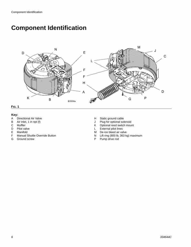
Key:A Directional Air ValveB Air inlet, 1 in npt (f)C MufflerD Pilot valveE ManifoldF Manual Shuttle Override ButtonG Ground screw
H Static ground cableJ Plug for optional solenoidK Optional reed switch mountL External pilot linesM De-ice bleed air valveN Lift ring (800 lb, 363 kg) maximumP Pump drive rod
FIG. 1
6 334644C
General Information
General InformationThe XL 10000 air motor is air piloted with two poppet valves operating a cup and plate main air shuttle valve. Air exhausts around the cylinder, through sound absorp-tion materials, and out the rear bottom of the shroud.
ApplicationThis motor has 7% larger effective area, and is intended to directly replace, the Graco Premier® motor. The XL will acceptthesameM16x 2.0 threaded tie rods, the same connecting rods, and the same 3/8-16 mounting studs used with the Premier. The XL motor is physically smaller than the Premier, so it will fit anywhere the Pre-mier is used. The 1 in. air inlet is at a low front position instead of up on the top so a different air hose may be required. There are also threaded cart/shelf type mount-ing holes in the base which match the ones used on the NXT® motors. The XL motor fits the standard heavy duty Xtreme cart so the larger Premier cart is no longer necessary.
Reciprocating Signal PoppetsThe poppets are identical to the ones used in the Graco Merkur® motors and many air-operated double dia-phragm motors. Poppets are fully accessible and can easily be replaced.
External Pilot LinesThe pilot lines (L) that run from the shuttle end ports to the exhaust poppets are run externally in hydraulic hose. This allows for cold weather operation without running the air through the aluminum manifold, which can sometimes get cold enough for airline moisture to freeze and block the signals.
Manual Override ButtonsThere are manual override buttons (F) on each end of the air valve that allows the internal main shuttle valve to be physically moved from one position to the other. Run the motor manually to:
• Move the valve off center due to ice or debris.
• Flush a pump if a poppet is plugged, stuck in the open position, or the signal is leaking.
See Run Motor Manually on page 9.
Low Pressure OperationThis motor will run at 4–5 psi (20.6–27.5 kPa, 0.21–0.27 bar)
PerformanceThe air valve (A), manifold (E), and exhaust are larger than the Premier air handling parts in order to exhaust the 630 in3 of compressed air from the cylinder after a full stroke. This allows the • uid pressure to come back faster as the piston is driven from the other side. The near square pressure trace that this generates makes for a small change-over pulse, and full pressure output for running multiple guns.
Minimum IcingThe oversizing of all the air handling parts described in the General Information section mean that normal air motor ice buildup has less effect on the pump output.
Bleed AirUse the de-ice bleed air valve (M) to run warm air through the valve and exhaust for de-icing. This is mainly helpful during warm weather, very high humidity applications, or low pressure high cycle rate applica-tions.
Extended CapabilitiesThe XL motor will accept DataTrak™ counting, a run-away stop solenoid, and the top mount linear position transducer used with NXT motors.
334644C 7
Grounding
Grounding
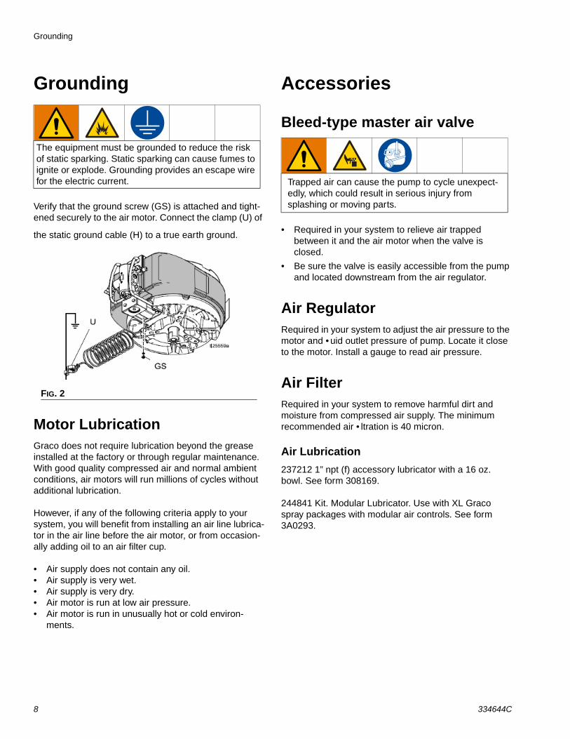
Verify that the ground screw (GS) is attached and tight-ened securely to the air motor. Connect the clamp (U) of
the static ground cable (H) to a true earth ground.
Motor LubricationGraco does not require lubrication beyond the grease installed at the factory or through regular maintenance. With good quality compressed air and normal ambient conditions, air motors will run millions of cycles without additional lubrication.
However, if any of the following criteria apply to your system, you will benefit from installing an air line lubrica-tor in the air line before the air motor, or from occasion-ally adding oil to an air filter cup.
• Air supply does not contain any oil.• Air supply is very wet.• Air supply is very dry.• Air motor is run at low air pressure.• Air motor is run in unusually hot or cold environ-
ments.
Accessories
Bleed-type master air valve
• Required in your system to relieve air trapped between it and the air motor when the valve is closed.
• Be sure the valve is easily accessible from the pump and located downstream from the air regulator.
Air RegulatorRequired in your system to adjust the air pressure to the motor and • uid outlet pressure of pump. Locate it close to the motor. Install a gauge to read air pressure.
Air FilterRequired in your system to remove harmful dirt and moisture from compressed air supply. The minimum recommended air • ltration is 40 micron.
Air Lubrication237212 1” npt (f) accessory lubricator with a 16 oz. bowl. See form 308169.
244841 Kit. Modular Lubricator. Use with XL Graco spray packages with modular air controls. See form 3A0293.
The equipment must be grounded to reduce the risk of static sparking. Static sparking can cause fumes to ignite or explode. Grounding provides an escape wire for the electric current.
FIG. 2
Trapped air can cause the pump to cycle unexpect-edly, which could result in serious injury from splashing or moving parts.
8 334644C
Grounding
Run Motor ManuallyUse the manual override buttons (F) on each end of theair valve to physically move the internal main shuttlevalve from one position to the other. Run the motor man-ually to:
• Move the valve off center due to ice or debris.
• Flush a pump if a poppet is plugged, stuck in the open position, or the signal is leaking
1. Lower the air pressure to approximately 30–40 psi (2.1 kPa, 210 bar – 280 kPa, 2.8 bar) to manually operation the buttons.
2. If a poppet is plugged:
a. Press the button on the end where the motor stopped. This will cause the motor to run another cycle.
b. Press the button again to finish flushing.
3. If a poppet is stuck in the open position or the signal is leaking:
a. Press the button on the opposite end from where the motor stopped and hold it in. This will cause the motor to stroke to the other end.
b. Release the button to allow the motor to stroke back.
NOTE: For poppet issues, the motor can also be manu-ally operated by disconnecting the pilot hose and con-trolling the pilot signal exhaust with your • nger.
334644C 9
Troubleshooting
Troubleshooting
Problem Cause Solution
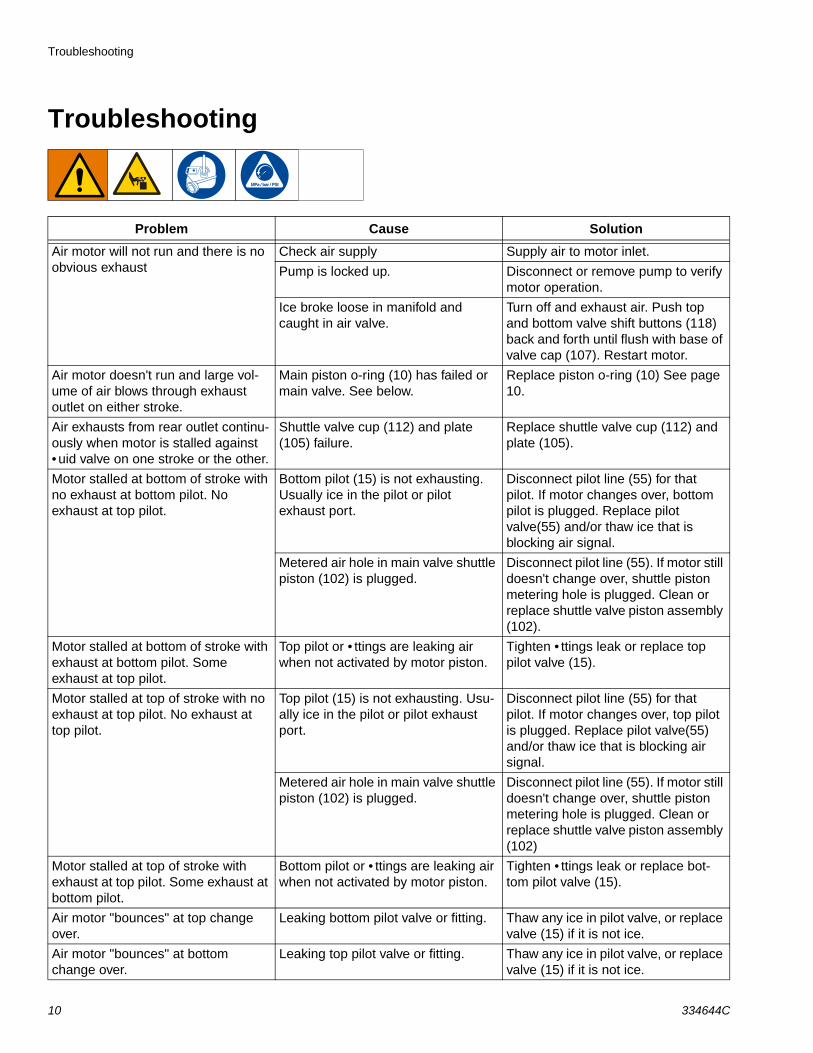
Air motor will not run and there is no obvious exhaust
Check air supply Supply air to motor inlet.
Pump is locked up. Disconnect or remove pump to verify motor operation.
Ice broke loose in manifold and caught in air valve.
Turn off and exhaust air. Push top and bottom valve shift buttons (118) back and forth until flush with base of valve cap (107). Restart motor.
Air motor doesn't run and large vol-ume of air blows through exhaust outlet on either stroke.
Main piston o-ring (10) has failed or main valve. See below.
Replace piston o-ring (10) See page 10.
Air exhausts from rear outlet continu-ously when motor is stalled against • uid valve on one stroke or the other.
Shuttle valve cup (112) and plate (105) failure.
Replace shuttle valve cup (112) and plate (105).
Motor stalled at bottom of stroke with no exhaust at bottom pilot. No exhaust at top pilot.
Bottom pilot (15) is not exhausting. Usually ice in the pilot or pilot exhaust port.
Disconnect pilot line (55) for that pilot. If motor changes over, bottom pilot is plugged. Replace pilot valve(55) and/or thaw ice that is blocking air signal.
Metered air hole in main valve shuttle piston (102) is plugged.
Disconnect pilot line (55). If motor still doesn't change over, shuttle piston metering hole is plugged. Clean or replace shuttle valve piston assembly (102).
Motor stalled at bottom of stroke with exhaust at bottom pilot. Some exhaust at top pilot.
Top pilot or • ttings are leaking air when not activated by motor piston.
Tighten • ttings leak or replace top pilot valve (15).
Motor stalled at top of stroke with no exhaust at top pilot. No exhaust at top pilot.
Top pilot (15) is not exhausting. Usu-ally ice in the pilot or pilot exhaust port.
Disconnect pilot line (55) for that pilot. If motor changes over, top pilot is plugged. Replace pilot valve(55) and/or thaw ice that is blocking air signal.
Metered air hole in main valve shuttle piston (102) is plugged.
Disconnect pilot line (55). If motor still doesn't change over, shuttle piston metering hole is plugged. Clean or replace shuttle valve piston assembly (102)
Motor stalled at top of stroke with exhaust at top pilot. Some exhaust at bottom pilot.
Bottom pilot or • ttings are leaking air when not activated by motor piston.
Tighten • ttings leak or replace bot-tom pilot valve (15).
Air motor "bounces" at top change over.
Leaking bottom pilot valve or fitting. Thaw any ice in pilot valve, or replace valve (15) if it is not ice.
Air motor "bounces" at bottom change over.
Leaking top pilot valve or fitting. Thaw any ice in pilot valve, or replace valve (15) if it is not ice.
10 334644C
Troubleshooting
Ice In Air MotorWhen compressed air is exhausted, the sudden drop in pressure causes the air temperature to drop below the freezing point. This causes any water liquid or vapor to turn to ice.
Higher air pressures pack high amounts of air and water vapor in each cycle and create more expansion and ice. Higher cycle rates also build up the ice and lower the motor temperature faster. It is important to select the correct motor and pump size to run at a lower pressure, and cycle slower.
Warm humid climates can produce high levels of icing because of the higher humidity levels. Low ambient tem-peratures near freezing make it easier for the motor parts to drop below freezing.
To minimize ice build-up:
• Lower the dew point of the compressed air. Use a refrigerated air dyer, coalescing • lter, or desiccant • lter to lower the water vapor content of the air.
• Raise the compressed air temperature. Warmer air going in helps the motor parts stay above freez-ing. Compressed air, especially at these volumes, is warm when compressed. Keep the air warm or stay near the compressor to reduce icing.
• Use the bleed air to clear ice build up.
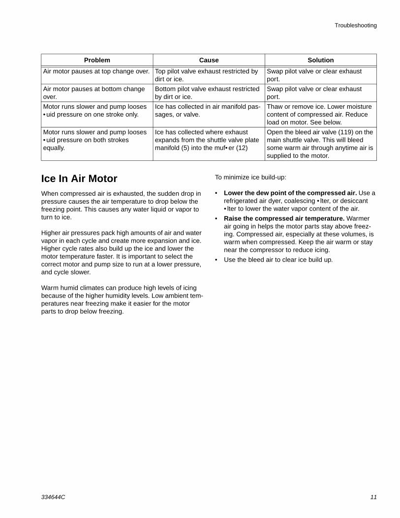
Air motor pauses at top change over. Top pilot valve exhaust restricted by dirt or ice.
Swap pilot valve or clear exhaust port.
Air motor pauses at bottom change over.
Bottom pilot valve exhaust restricted by dirt or ice.
Swap pilot valve or clear exhaust port.
Motor runs slower and pump looses • uid pressure on one stroke only.
Ice has collected in air manifold pas-sages, or valve.
Thaw or remove ice. Lower moisture content of compressed air. Reduce load on motor. See below.
Motor runs slower and pump looses • uid pressure on both strokes equally.
Ice has collected where exhaust expands from the shuttle valve plate manifold (5) into the muf• er (12)
Open the bleed air valve (119) on the main shuttle valve. This will bleed some warm air through anytime air is supplied to the motor.
Problem Cause Solution
334644C 11
Repair
Repair
Preventive Maintenance ScheduleThe operating conditions of your system determine how often maintenance is required. Establish a preventative maintenance schedule by recording when and what kind of maintenance is needed, and then determine a regular schedule for checking your system.
Pressure Relief Procedure
1. Engage trigger lock.
2. Close the bleed-type master air valve.
3. Disengage the trigger lock.
4. Hold a metal part of the gun firmly to a grounded metal pail. Trigger the gun to relieve pressure.
5. Engage the trigger lock.
6. Open all • uid drain valves in the system, having a waste container ready to catch drainage. Leave drain valve(s) open until you are ready to spray again.
7. If you suspect the spray tip or hose is clogged or that pressure has not been fully relieved:
a. VERY SLOWLY loosen tip guard retaining nut or hose end coupling to relieve pressure gradu-ally.
b. Loosen nut or coupling completely.
c. Clear hose or tip obstruction.
Follow the Pressure Relief Procedure whenever you see this symbol
This equipment stays pressurized until pressure is manually relieved. To help prevent serious injury from pressurized • uid, such as skin injection, splashing • uid and moving parts, follow the Pressure Relief Procedure when you stop spraying and before cleaning, checking, or servicing equipment.
12 334644C
Repair
Repair Air Valve
Replace Complete Air Valve
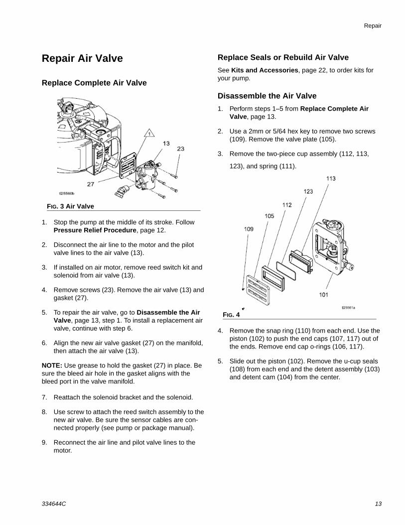
1. Stop the pump at the middle of its stroke. Follow Pressure Relief Procedure, page 12.
2. Disconnect the air line to the motor and the pilot valve lines to the air valve (13).
3. If installed on air motor, remove reed switch kit and solenoid from air valve (13).
4. Remove screws (23). Remove the air valve (13) and gasket (27).
5. To repair the air valve, go to Disassemble the Air Valve, page 13, step 1. To install a replacement air valve, continue with step 6.
6. Align the new air valve gasket (27) on the manifold, then attach the air valve (13).
NOTE: Use grease to hold the gasket (27) in place. Be sure the bleed air hole in the gasket aligns with the bleed port in the valve manifold.
7. Reattach the solenoid bracket and the solenoid.
8. Use screw to attach the reed switch assembly to the new air valve. Be sure the sensor cables are con-nected properly (see pump or package manual).
9. Reconnect the air line and pilot valve lines to the motor.
Replace Seals or Rebuild Air ValveSee Kits and Accessories, page 22, to order kits for your pump.
Disassemble the Air Valve1. Perform steps 1–5 from Replace Complete Air
Valve, page 13.
2. Use a 2mm or 5/64 hex key to remove two screws (109). Remove the valve plate (105).
3. Remove the two-piece cup assembly (112, 113,
123), and spring (111).
4. Remove the snap ring (110) from each end. Use the piston (102) to push the end caps (107, 117) out of the ends. Remove end cap o-rings (106, 117).
5. Slide out the piston (102). Remove the u-cup seals (108) from each end and the detent assembly (103) and detent cam (104) from the center.
FIG. 3 Air Valve
FIG. 4
334644C 13
Repair
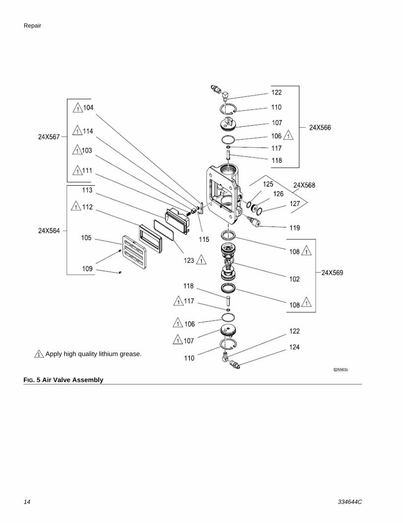
FIG. 5 Air Valve Assembly
Apply high quality lithium grease.1
14 334644C
Repair
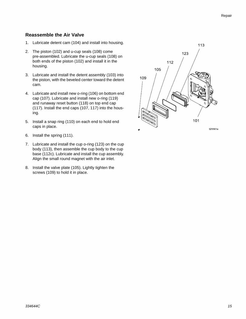
Reassemble the Air Valve1. Lubricate detent cam (104) and install into housing.
2. The piston (102) and u-cup seals (108) come pre-assembled. Lubricate the u-cup seals (108) on both ends of the piston (102) and install it in the housing.
3. Lubricate and install the detent assembly (103) into the piston, with the beveled center toward the detent cam.
4. Lubricate and install new o-ring (106) on bottom end cap (107). Lubricate and install new o-ring (119) and runaway reset button (118) on top end cap (117). Install the end caps (107, 117) into the hous-ing.
5. Install a snap ring (110) on each end to hold end caps in place.
6. Install the spring (111).
7. Lubricate and install the cup o-ring (123) on the cup body (113), then assemble the cup body to the cup base (112c). Lubricate and install the cup assembly. Align the small round magnet with the air inlet.
8. Install the valve plate (105). Lightly tighten the screws (109) to hold it in place.
334644C 15
Repair
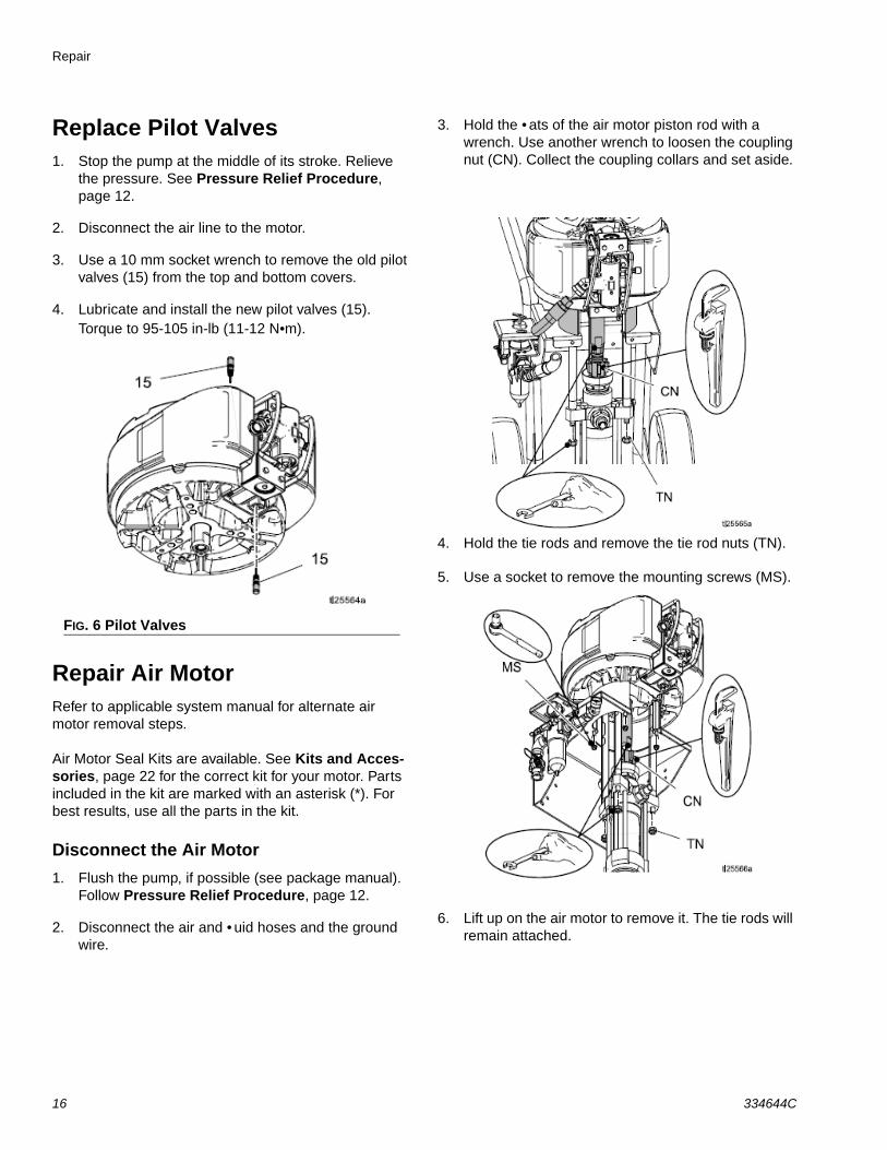
Replace Pilot Valves1. Stop the pump at the middle of its stroke. Relieve
the pressure. See Pressure Relief Procedure, page 12.
2. Disconnect the air line to the motor.
3. Use a 10 mm socket wrench to remove the old pilot valves (15) from the top and bottom covers.
4. Lubricate and install the new pilot valves (15). Torque to 95-105 in-lb (11-12 N•m).
Repair Air MotorRefer to applicable system manual for alternate air motor removal steps.
Air Motor Seal Kits are available. See Kits and Acces-sories, page 22 for the correct kit for your motor. Parts included in the kit are marked with an asterisk (*). For best results, use all the parts in the kit.
Disconnect the Air Motor1. Flush the pump, if possible (see package manual).
Follow Pressure Relief Procedure, page 12.
2. Disconnect the air and • uid hoses and the ground wire.
3. Hold the • ats of the air motor piston rod with a wrench. Use another wrench to loosen the coupling nut (CN). Collect the coupling collars and set aside.
4. Hold the tie rods and remove the tie rod nuts (TN).
5. Use a socket to remove the mounting screws (MS).
6. Lift up on the air motor to remove it. The tie rods will remain attached.
FIG. 6 Pilot Valves
16 334644C
Repair
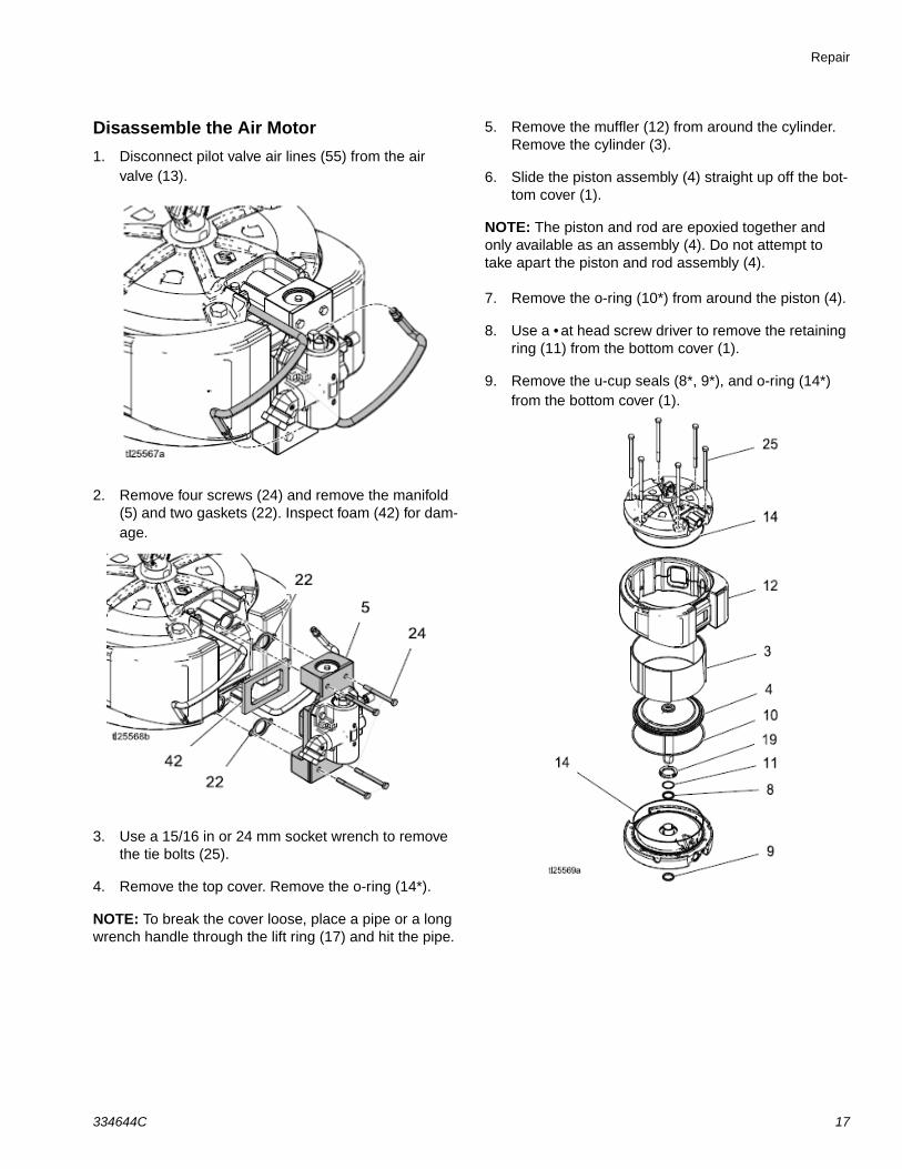
Disassemble the Air Motor1. Disconnect pilot valve air lines (55) from the air
valve (13).
2. Remove four screws (24) and remove the manifold (5) and two gaskets (22). Inspect foam (42) for dam-age.
3. Use a 15/16 in or 24 mm socket wrench to remove the tie bolts (25).
4. Remove the top cover. Remove the o-ring (14*).
NOTE: To break the cover loose, place a pipe or a long wrench handle through the lift ring (17) and hit the pipe.
5. Remove the muffler (12) from around the cylinder. Remove the cylinder (3).
6. Slide the piston assembly (4) straight up off the bot-tom cover (1).
NOTE: The piston and rod are epoxied together and only available as an assembly (4). Do not attempt to take apart the piston and rod assembly (4).
7. Remove the o-ring (10*) from around the piston (4).
8. Use a • at head screw driver to remove the retaining ring (11) from the bottom cover (1).
9. Remove the u-cup seals (8*, 9*), and o-ring (14*) from the bottom cover (1).
334644C 17
Repair
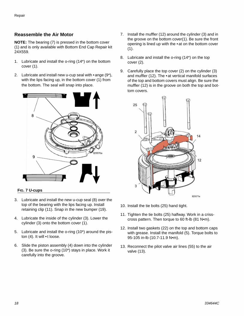
Reassemble the Air MotorNOTE: The bearing (7) is pressed in the bottom cover (1) and is only available with Bottom End Cap Repair kit 24X559.
1. Lubricate and install the o-ring (14*) on the bottom cover (1).
2. Lubricate and install new u-cup seal with • ange (9*), with the lips facing up, in the bottom cover (1) from the bottom. The seal will snap into place.
3. Lubricate and install the new u-cup seal (8) over the top of the bearing with the lips facing up. Install retaining clip (11). Snap in the new bumper (19).
4. Lubricate the inside of the cylinder (3). Lower the cylinder (3) onto the bottom cover (1).
5. Lubricate and install the o-ring (10*) around the pis-ton (4). It will • t loose.
6. Slide the piston assembly (4) down into the cylinder (3). Be sure the o-ring (10*) stays in place. Work it carefully into the groove.
7. Install the muffler (12) around the cylinder (3) and in the groove on the bottom cover(1). Be sure the front opening is lined up with the • at on the bottom cover (1).
8. Lubricate and install the o-ring (14*) on the top cover (2).
9. Carefully place the top cover (2) on the cylinder (3) and muffler (12). The • at vertical manifold surfaces of the top and bottom covers must align. Be sure the muffler (12) is in the groove on both the top and bot-tom covers.
10. Install the tie bolts (25) hand tight.
11. Tighten the tie bolts (25) halfway. Work in a criss-cross pattern. Then torque to 60 ft-lb (81 N•m).
12. Install two gaskets (22) on the top and bottom caps with grease. Install the manifold (5). Torque bolts to 95-105 in-lb (10.7-11.9 N•m).
13. Reconnect the pilot valve air lines (55) to the air valve (13).
FIG. 7 U-cups
18 334644C
Parts
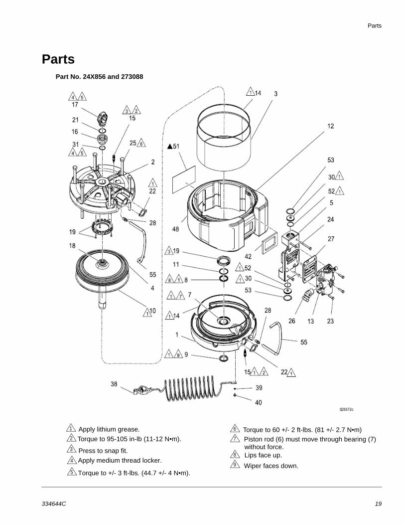
PartsPart No. 24X856 and 273088
Apply lithium grease.
Torque to 95-105 in-lb (11-12 N•m). Press to snap fit.
Apply medium thread locker.
Torque to +/- 3 ft-lbs. (44.7 +/- 4 N•m).
1
4
3
2
5
8
7
9
6 Torque to 60 +/- 2 ft-lbs. (81 +/- 2.7 N•m) Piston rod (6) must move through bearing (7) without force.Lips face up.
Wiper faces down.
334644C 19
Parts
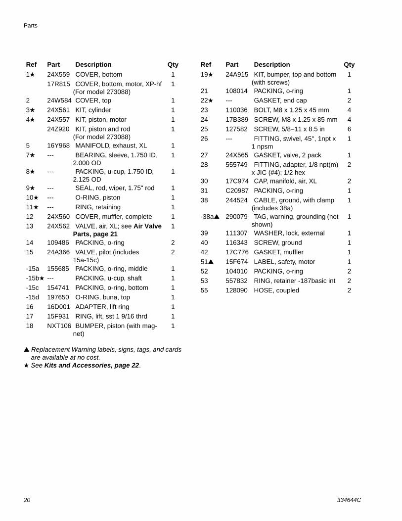
Replacement Warning labels, signs, tags, and cards are available at no cost. See Kits and Accessories, page 22.
Ref Part Description Qty1 24X559 COVER, bottom 1
17R815 COVER, bottom, motor, XP-hf (For model 273088)
1
2 24W584 COVER, top 1
3 24X561 KIT, cylinder 1
4 24X557 KIT, piston, motor 1
24Z920 KIT, piston and rod (For model 273088)
1
5 16Y968 MANIFOLD, exhaust, XL 1
7 --- BEARING, sleeve, 1.750 ID, 2.000 OD
1
8 --- PACKING, u-cup, 1.750 ID, 2.125 OD
1
9 --- SEAL, rod, wiper, 1.75" rod 1
10 --- O-RING, piston 1
11 --- RING, retaining 1
12 24X560 COVER, muffler, complete 1
13 24X562 VALVE, air, XL; see Air Valve Parts, page 21
1
14 109486 PACKING, o-ring 2
15 24A366 VALVE, pilot (includes 15a-15c)
2
-15a 155685 PACKING, o-ring, middle 1
-15b --- PACKING, u-cup, shaft 1
-15c 154741 PACKING, o-ring, bottom 1
-15d 197650 O-RING, buna, top 1
16 16D001 ADAPTER, lift ring 1
17 15F931 RING, lift, sst 1 9/16 thrd 1
18 NXT106 BUMPER, piston (with mag-net)
1
Ref Part Description Qty19 24A915 KIT, bumper, top and bottom
(with screws)1
21 108014 PACKING, o-ring 1
22 --- GASKET, end cap 2
23 110036 BOLT, M8 x 1.25 x 45 mm 4
24 17B389 SCREW, M8 x 1.25 x 85 mm 4
25 127582 SCREW, 5/8–11 x 8.5 in 6
26 --- FITTING, swivel, 45°, 1npt x 1 npsm
1
27 24X565 GASKET, valve, 2 pack 1
28 555749 FITTING, adapter, 1/8 npt(m) x JIC (#4); 1/2 hex
2
30 17C974 CAP, manifold, air, XL 2
31 C20987 PACKING, o-ring 1
38 244524 CABLE, ground, with clamp (includes 38a)
1
-38a 290079 TAG, warning, grounding (not shown)
1
39 111307 WASHER, lock, external 1
40 116343 SCREW, ground 1
42 17C776 GASKET, muffler 1
51 15F674 LABEL, safety, motor 1
52 104010 PACKING, o-ring 2
53 557832 RING, retainer -187basic int 2
55 128090 HOSE, coupled 2
20 334644C
Parts
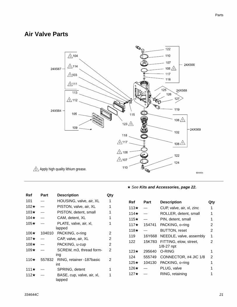
Air Valve Parts
See Kits and Accessories, page 22.
1 Apply high quality lithium grease.
Ref Part Description Qty101 --- HOUSING, valve, air, XL 1
102 --- PISTON, valve, air, XL 1
103 --- PISTON, detent, small 1
104 --- CAM, detent, XL 1
105 --- PLATE, valve, air, xl, lapped
1
106 104010 PACKING, o-ring 2
107 --- CAP, valve, air, XL 2
108 --- PACKING, u-cup 2
109 --- SCREW, m3, thread form-ing
2
110 557832 RING, retainer -187basic int
2
111 --- SPRING, detent 1
112 --- BASE, cup, valve, air, xl, lapped
1
Ref Part Description Qty113 --- CUP, valve, air, xl, zinc 1
114 --- ROLLER, detent, small 1
115 --- PIN, detent, small 1
117 154741 PACKING, o-ring 2
118 --- BUTTON, reset 2
119 16Y668 NEEDLE, valve, assembly 1
122 15K783 FITTING, elow, street, 1/8-27 npt
2
123 295640 O-RING 1
124 555749 CONNECTOR, #4 JIC 1/8 2
125 104130 PACKING, o-ring 1
126 --- PLUG, valve 1
127 --- RING, retaining 1
334644C 21
Parts
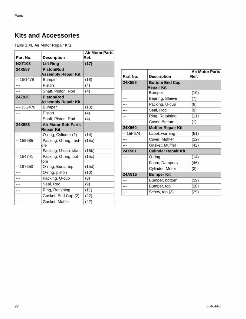
Kits and AccessoriesTable 1 XL Air Motor Repair Kits
Part No. DescriptionAir Motor Parts
Ref.NXT103 Lift Ring (17)24X557 Piston/Rod
Assembly Repair Kit-- 15G478 Bumper (18)
--- Piston (4)
--- Shaft, Piston, Rod (4)
24Z920 Piston/Rod Assembly Repair Kit
--- 15G478 Bumper (18)
--- Piston (4)
--- Shaft, Piston, Rod (4)
24X558 Air Motor Soft Parts Repair Kit
--- O-ring, Cylinder (2) (14)
-- 155685 Packing, O-ring, mid-dle
(15a)
--- Packing, U-cup, shaft (15b)
-- 154741 Packing, O-ring, bot-tom
(15c)
-- 197650 O-ring, Buna, top (15d)
--- O-ring, piston (10)
--- Packing, U-cup (8)
--- Seal, Rod (9)
--- Ring, Retaining (11)
--- Gasket, End Cap (2) (22)
--- Gasket, Muffler (42)
Part No. DescriptionAir Motor Parts
Ref.24X559 Bottom End Cap
Repair Kit--- Bumper (19)
--- Bearing, Sleeve (7)
--- Packing, U-cup (8)
--- Seal, Rod (9)
--- Ring, Retaining (11)
--- Cover, Bottom (1)
24X560 Muffler Repair Kit-- 15F674 Label, warning (51)
--- Cover, Muffler (12)
--- Gasket, Muffler (42)
24X561 Cylinder Repair Kit--- O-ring (14)
--- Foam, Dampers (46)
--- Cylinder, Motor (3)
24A915 Bumper Kit--- Bumper, bottom (19)
--- Bumper, top (20)
--- Screw, top (3) (29)
22 334644C
Parts
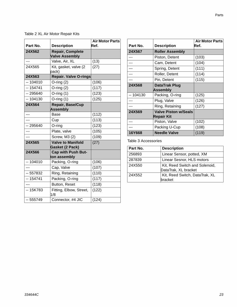
Table 2 XL Air Motor Repair Kits
Table 3 Accessories
Part No. DescriptionAir Motor Parts
Ref.24X562 Repair, Complete
Valve Assembly--- Valve, Air, XL (13)
24X565 Kit, gasket, valve (2 pack)
(27)
24X563 Repair. Valve O-rings-- 104010 O-ring (2) (106)
-- 154741 O-ring (2) (117)
-- 295640 O-ring (1) (123)
-- 104130 O-ring (1) (125)
24X564 Repair, Base/Cup Assembly
--- Base (112)
--- Cup (113)
-- 295640 O-ring (123)
--- Plate, valve (105)
--- Screw, M3 (2) (109)
24X565 Valve to Manifold Gasket (2 Pack)
(27)
24X566 Cap with Push But-ton assembly
-- 104010 Packing, O-ring (106)
--- Cap, Valve (107)
-- 557832 Ring, Retaining (110)
-- 154741 Packing, O-ring (117)
--- Button, Reset (118)
-- 15K783 Fitting, Elbow, Street, 1/8
(122)
-- 555749 Connector, #4 JIC (124)
Part No. DescriptionAir Motor Parts
Ref.24X567 Roller Assembly--- Piston, Detent (103)
--- Cam, Detent (104)
--- Spring, Detent (111)
--- Roller, Detent (114)
--- Pin, Detent (115)
24X568 DataTrak Plug Assembly
-- 104130 Packing, O-ring (125)
--- Plug, Valve (126)
--- Ring, Retaining (127)
24X569 Valve Piston w/Seals Repair Kit
--- Piston, Valve (102)
--- Packing U-Cup (108)
16Y668 Needle Valve (119)
Part No. Description256893 Linear Sensor, potted, XM
287839 Linear Sesnor, HLS motors
24X550 Kit, Reed Switch and Solenoid, DataTrak, XL bracket
24X552 Kit, Reed Switch, DataTrak, XL bracket
334644C 23
Dimensions (Model No. 24X856)
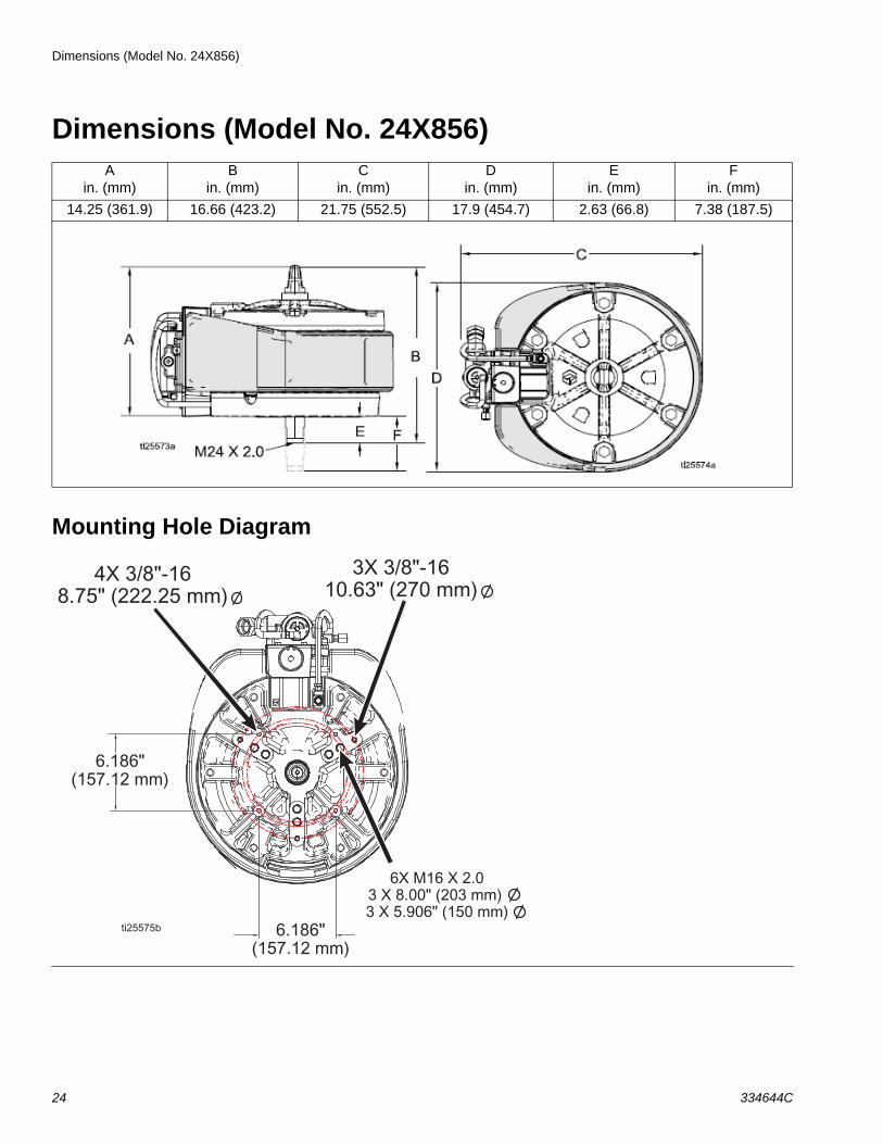
Dimensions (Model No. 24X856)
Mounting Hole Diagram
Ain. (mm)
Bin. (mm)
Cin. (mm)
Din. (mm)
Ein. (mm)
Fin. (mm)
14.25 (361.9) 16.66 (423.2) 21.75 (552.5) 17.9 (454.7) 2.63 (66.8) 7.38 (187.5)
24 334644C
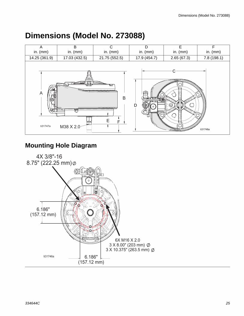
Dimensions (Model No. 273088)
Dimensions (Model No. 273088)
Mounting Hole Diagram
Ain. (mm)
Bin. (mm)
Cin. (mm)
Din. (mm)
Ein. (mm)
Fin. (mm)
14.25 (361.9) 17.03 (432.5) 21.75 (552.5) 17.9 (454.7) 2.65 (67.3) 7.8 (198.1)
334644C 25
Technical Specifications
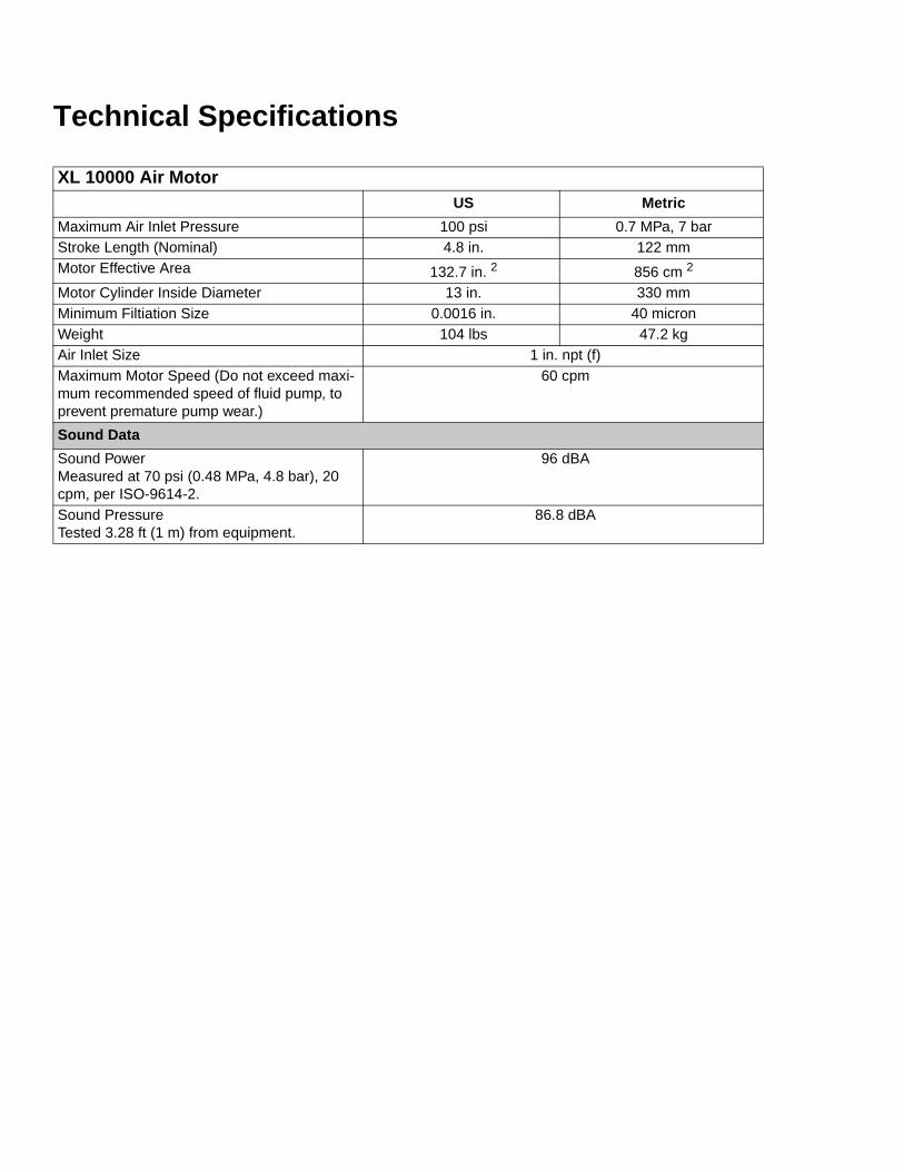
XL 10000 Air MotorUS Metric
Maximum Air Inlet Pressure 100 psi 0.7 MPa, 7 barStroke Length (Nominal) 4.8 in. 122 mmMotor Effective Area 132.7 in. 2 856 cm 2
Motor Cylinder Inside Diameter 13 in. 330 mmMinimum Filtiation Size 0.0016 in. 40 micronWeight 104 lbs 47.2 kgAir Inlet Size 1 in. npt (f)Maximum Motor Speed (Do not exceed maxi-mum recommended speed of fluid pump, to prevent premature pump wear.)
60 cpm
Sound DataSound Power Measured at 70 psi (0.48 MPa, 4.8 bar), 20 cpm, per ISO-9614-2.
96 dBA
Sound PressureTested 3.28 ft (1 m) from equipment.
86.8 dBA
Graco Standard WarrantyGraco warrants all equipment referenced in this document which is manufactured by Graco and bearing its name to be free from defects in material and workmanship on the date of sale to the original purchaser for use. With the exception of any special, extended, or limited warranty published by Graco, Graco will, for a period of twelve months from the date of sale, repair or replace any part of the equipment determined by Graco to be defective. This warranty applies only when the equipment is installed, operated and maintained in accordance with Graco’s written recommendations.
This warranty does not cover, and Graco shall not be liable for general wear and tear, or any malfunction, damage or wear caused by faulty installation, misapplication, abrasion, corrosion, inadequate or improper maintenance, negligence, accident, tampering, or substitution of non-Graco component parts. Nor shall Graco be liable for malfunction, damage or wear caused by the incompatibility of Graco equipment with structures, accessories, equipment or materials not supplied by Graco, or the improper design, manufacture, installation, operation or maintenance of structures, accessories, equipment or materials not supplied by Graco.
This warranty is conditioned upon the prepaid return of the equipment claimed to be defective to an authorized Graco distributor for veri• cation of the claimed defect. If the claimed defect is veri• ed, Graco will repair or replace free of charge any defective parts. The equipment will be returned to the original purchaser transportation prepaid. If inspection of the equipment does not disclose any defect in material or workmanship, repairs will be made at a reasonable charge, which charges may include the costs of parts, labor, and transportation
THIS WARRANTY IS EXCLUSIVE, AND IS IN LIEU OF ANY OTHER WARRANTIES, EXPRESS OR IMPLIED, INCLUDING BUT NOT LIMITED TO WARRANTY OF MERCHANTABILITY OR WARRANTY OF FITNESS FOR A PARTICULAR PURPOSE.
Graco’s sole obligation and buyer’s sole remedy for any breach of warranty shall be as set forth above. The buyer agrees that no other remedy (including, but not limited to, incidental or consequential damages for lost pro• ts, lost sales, injury to person or property, or any other incidental or consequential loss) shall be available. Any action for breach of warranty must be brought within two (2) years of the date of sale.
GRACO MAKES NO WARRANTY, AND DISCLAIMS ALL IMPLIED WARRANTIES OF MERCHANTABILITY AND FITNESS FOR A PARTICULAR PURPOSE, IN CONNECTION WITH ACCESSORIES, EQUIPMENT, MATERIALS OR COMPONENTS SOLD BUT NOT MANUFACTURED BY GRACO. These items sold, but not manufactured by Graco (such as electric motors, switches, hose, etc.), are subject to the warranty, if any, of their manufacturer. Graco will provide purchaser with reasonable assistance in making any claim for breach of these warranties.
In no event will Graco be liable for indirect, incidental, special or consequential damages resulting from Graco supplying equipment hereunder, or the furnishing, performance, or use of any products or other goods sold hereto, whether due to a breach of contract, breach of warranty, the negligence of Graco, or otherwise.
FOR GRACO CANADA CUSTOMERSThe Parties acknowledge that they have required that the present document, as well as all documents, notices and legal proceedings entered into, given or instituted pursuant hereto or relating directly or indirectly hereto, be drawn up in English. Les parties reconnaissent avoir convenu que la rédaction du présente document sera en Anglais, ainsi que tous documents, avis et procédures judiciaires exécutés, donnés ou intentés, à la suite de ou en rapport, directement ou indirectement, avec les procédures concernées.
Graco InformationFor the latest information about Graco products, visit www.graco.com.
For patent information, see www.graco.com/patents.
TO PLACE AN ORDER, contact your Graco distributor or call to identify the nearest dis-tributor.Phone: 612-623-6921 or Toll Free: 1-800-328-0211 Fax: 612-378-3505
All written and visual data contained in this document reflects the latest product information available at the time of publication. Graco reserves the right to make changes at any time without notice.
Original instructions. This manual contains English. MM 334644Graco Headquarters: Minneapolis
International Offices: Belgium, China, Japan, Korea
GRACO INC. AND SUBSIDIARIES • P.O. BOX 1441 • MINNEAPOLIS MN 55440-1441 • USACopyright 2015, Graco Inc. All Graco manufacturing locations are registered to ISO 9001.
www.graco.comRevision C, June 2017