Embed Size (px)
Citation preview
Transverse Spin Physics with PHENIX Xiaodong Jiang
Los Alamos Na?onal Laboratory June, 12th, 2012@RHIC/AGS User’s Mee?ng Spin Workshop
• Updates of Preliminary SSA Results. • Run2012 transverse p+p data.
• FVTX commissioning. • Single-‐muon triggers for p>5 GeV (SG3 trigger).
• Expecta?ons for Run2013 p+p@510 GeV. • Drell-‐Yan longitudinal spin observables at 510 GeV.
• Run2014 and beyond • MPC-‐EX upgrade. Prompt photon SSA.
• sPHENIX forward upgrade, for SSA (tomorrow’s talk).
1
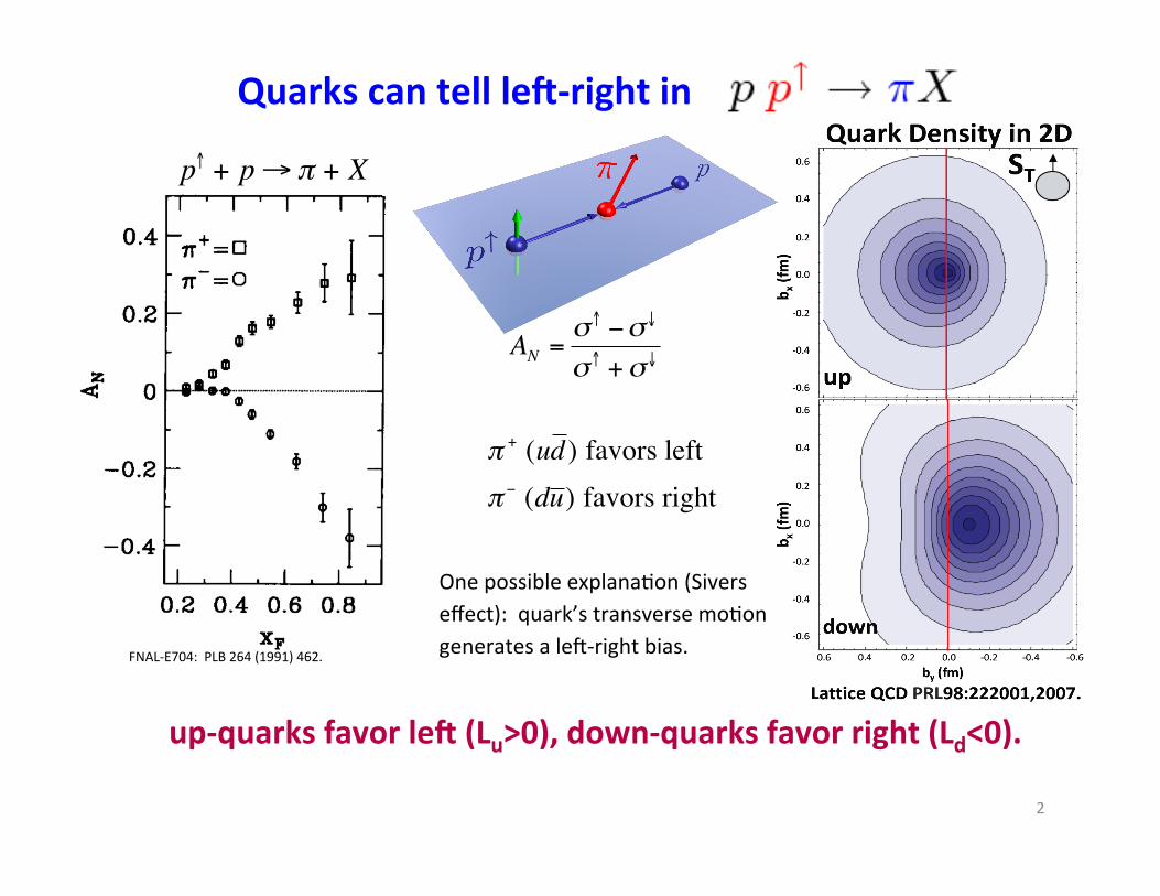
up-‐quarks favor le/ (Lu>0), down-‐quarks favor right (Ld<0).
One possible explana?on (Sivers effect): quark’s transverse mo?on generates a lec-‐right bias.
FNAL-‐E704: PLB 264 (1991) 462.
!
p" + p#$ + X
!
AN ="# $"%
"# +"%
& + (ud ) favors left&$ (du ) favors right
Quarks can tell le/-‐right in
2

3
SSA observed in PHENIX: MPC Single Clusters
However, two mechanisms can not be dis?nguished in AN of inclusive hadron produc?on in p+p: Collins effect: quark transverse spin (transversity) generates a lec-‐right bias through fragmenta?on. Sivers effect: quark transverse mo?on generates a lec-‐right bias.

4
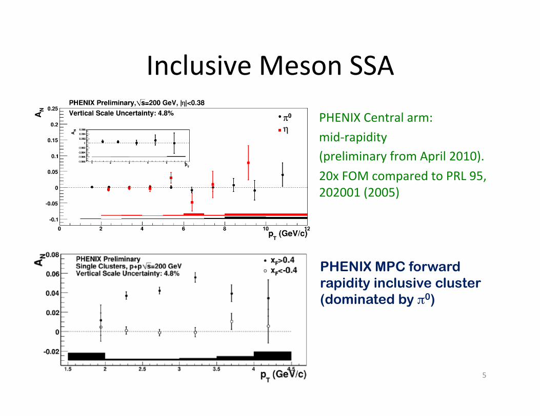
Inclusive Meson SSA
5
PHENIX Central arm: mid-‐rapidity (preliminary from April 2010). 20x FOM compared to PRL 95, 202001 (2005)
PHENIX MPC forward rapidity inclusive cluster (dominated by π0)

Single Cluster AN vs xF
xF
Cluster Contribu?ons
π0
γ PHENIX MPC @200 GeV
6
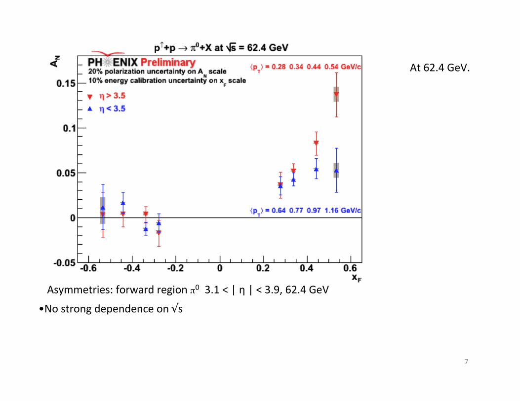
• No strong dependence on √s Asymmetries: forward region π0 3.1 < | η | < 3.9, 62.4 GeV
At 62.4 GeV.
7

η Transverse Asymmetries
8
Run8 preliminary
Working on cross sections

Asymmetries Forward Region: η @ 200 GeV
v Significant asymmetries observed. 9
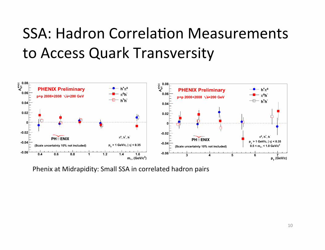
SSA: Hadron Correla?on Measurements to Access Quark Transversity
Phenix at Midrapidity: Small SSA in correlated hadron pairs
10

PHENIX Preliminary SSA from Other Probes
11
Preliminary results from earlier analysis
Heavy flavor decayed single-muons
Punch-through hadrons
Electrons at central rapidity.
Di-hadron back-to-back correlations
No significant SSA observed.
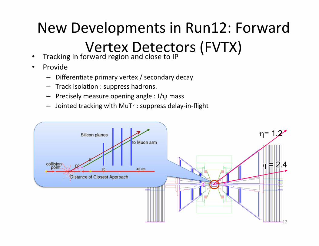
η= 1.2
η = 2.4
• Tracking in forward region and close to IP • Provide
– Differen?ate primary vertex / secondary decay – Track isola?on : suppress hadrons. – Precisely measure opening angle : J/ψ mass – Jointed tracking with MuTr : suppress delay-‐in-‐flight
12
New Developments in Run12: Forward Vertex Detectors (FVTX)
13
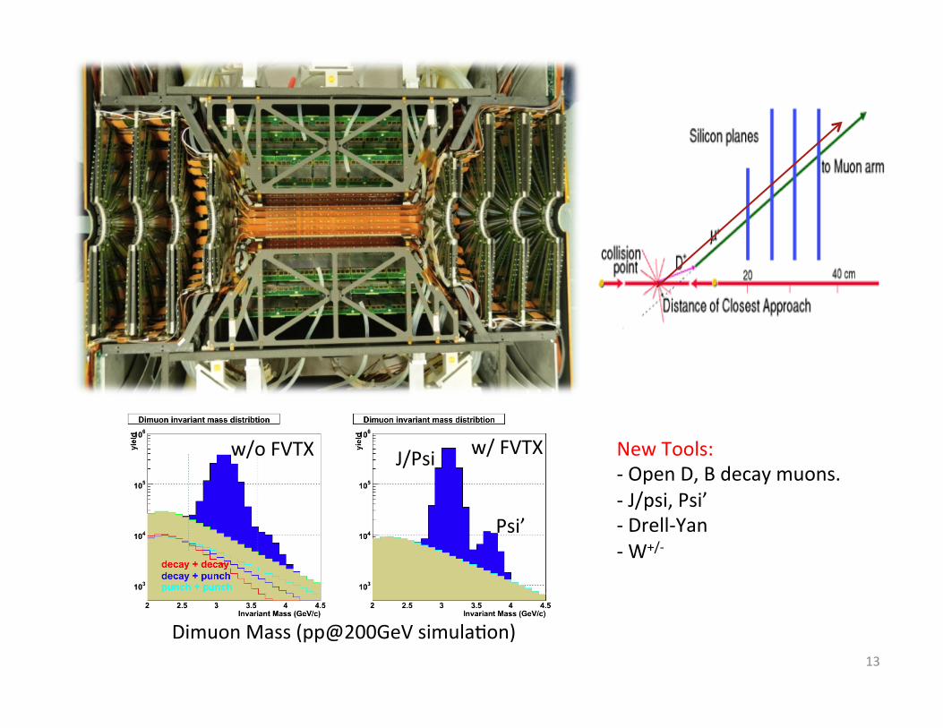
Dimuon Mass (pp@200GeV simula?on)
w/ FVTX J/Psi
Psi’
New Tools: -‐ Open D, B decay muons. -‐ J/psi, Psi’ -‐ Drell-‐Yan -‐ W+/-‐
w/o FVTX
New Developments During Run12
Goal: to obtain high staDsDc data on muTr singles. Event data needed: single-‐muons for physics AN prefer p> 5 GeV/c, as much as possible. Prepara?ons: • hit paperns of muTrg SG3 for p>4 GeV/c muons. • verify trigger efficiency by emula?on code and by data. • adjust prescale factors online for best sta?s?cs. • Verify again by data, compare SG3 vs MB trigger.
SG3 trigger, for heavy flavor decayed muons.
14
North South
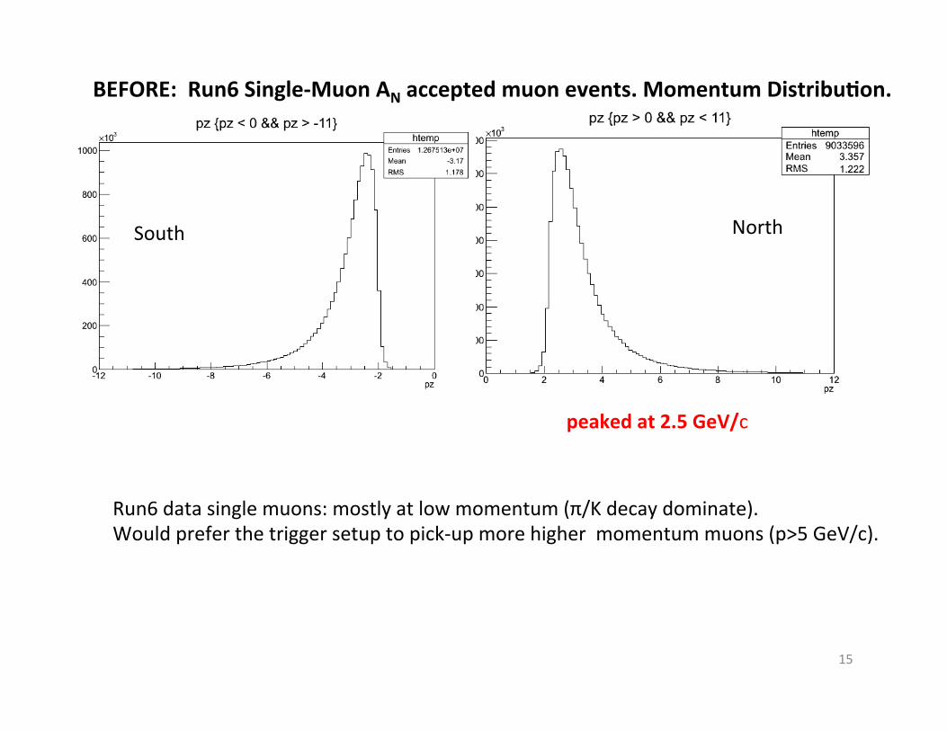
BEFORE: Run6 Single-‐Muon AN accepted muon events. Momentum DistribuDon.
Run6 data single muons: mostly at low momentum (π/K decay dominate). Would prefer the trigger setup to pick-‐up more higher momentum muons (p>5 GeV/c).
peaked at 2.5 GeV/c
15
• A module address packet, which indicates an ID numberof the MuTRG-DCMIF board.
• A clock counter, which indicates a beam-clock counter
value at the trigger reception.
After these header packets, the multiplexer reads hit data pack-
ets from the FIFO with changing their order according to a suit-
able format. The size of the data for each event becomes 2 oc-
tants × ( 96 strips for Station-1 + 192 strips for Station-2 +320 strips for Station-3 ) = 76 packets, where 1 packet = 16-bit.
At last, following trailers are added on the hit data packets to
complete making an output data array.
• Error packets, which indicate error flags onMuTRG-MRGand MuTRG-DCMIF.
• Longitudinal parity packet, which indicates longitudinalparity of all the packets in the event data. This value is
compared in DCM to confirm successful transmission.
As a result, the number of packets in the array for single trigger
is 5 (header) + 76 ×n (data) + 2 (trailer), where n is the size ofthe beam clock window for which events are transmitted.
Each data packet of the array is written to latter asynchronous
FIFO at a rate of 9.4 × 12 MHz. The written packets are
read with 80 MHz oscillator clock and sent to a transmitter,
TLK2501(Texas Instruments). The TLK2501 encodes the 16-
bit data packets into a serial signal with an effective serial rateof 1.6 Gbps, providing 1.28 Gbps of data bandwidth. The serial
signal are sent to DCM via an optical driver.
4.2.3. Control signals for MuTRG-DCMIF
Timing control signals for MuTRG-FEE system is originally
generated by GTM. A serial signal from GTM is decoded with
a deserializer chip, HDMP1024 (Hewlett Packard), into a col-
lection of control signals. Main signals used in MuTRG-FEE
system are the beam-clock signal, trigger accept signal and sev-
eral mode bit signals. The mode bit signals are translated into
reset signals forMuTRG-DCMIF,MuTRG-MRG andMuTRG-
ADTX on the FPGA. These signals are distributed to MuTRG-
MRG through category-6 Ethernet cables.
As well as MuTRG-MRG, MuTRG-DCMIF is also con-
trolled through VME bus. The control signals through VME
bus play following roles.
• Reset for registers
• Reset for a phase-locked loop (PLL)
• Configuration of FPGA and CPLD on MuTRG-DCMIF
• Setting of the number of transmitted events for each trigger
5. Muon Trigger Performance
5.1. Trigger logic
Fig. 29 schematically displays the concept of the high-
momentum muon trigger. The trigger is generated based on hits
from each channel of MuTRG-ADTX. The basic idea to select
high-momentummuons is to find a straight trajectory originated
in the collision point from the hits from MuTRG-ADTX. There
are several parameters to optimize the trigger performance and
they are summarized below. The order of the items corresponds
to actual order of the operation. Detailed explanation is pro-
vided in the following sections.
1 Threshold for the pulse height. To be balanced between the
level of noise and signal pulse height. See Section 3.2.1
and 3.2.2.
2 CFD or LED. See Section 3.2.4
3 Timing window (LL1 width). See Section 5.1.1.
4 OR/AND of hits in multiple cathode planes in the same
station. See Section 5.1.2.
5 Clustering on/off. See Section 5.1.3.
6 Trigger map (acceptance window and sagitta). See Sec-
tion 5.1.4.
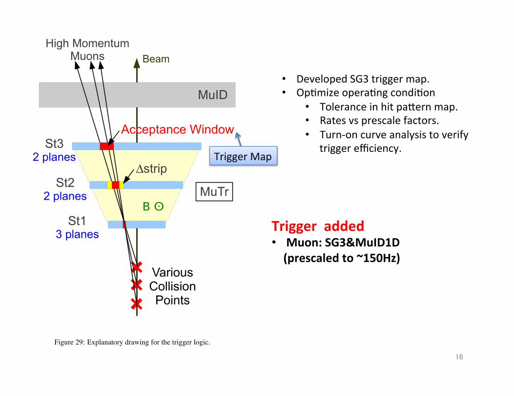
Figure 29: Explanatory drawing for the trigger logic.
5.1.1. Timing window (LL1 width)
As described in Section 3.2.3, because the timing resolution
spreads over two to three beam clocks, we open up the tim-
ing window to accommodate this in the MuTRG-MRG board.
19
Trigger Map
• Developed SG3 trigger map. • Op?mize opera?ng condi?on
• Tolerance in hit papern map. • Rates vs prescale factors. • Turn-‐on curve analysis to verify
trigger efficiency.
16
Trigger added • Muon: SG3&MuID1D (prescaled to ~150Hz)

Muon momentum (GeV/c)
North SG3 Trigger
South SG3 Trigger
North MuID Trigger
South MuID Trigger
North South
SG3 single-‐muon trigger efficiencies
AFTER peaked at 4 GeV/c
“Heavy Flavor muon trigger” func?oned at the end of 200 GeV p+p run, and in 510 GeV p+p run during run12.
17

Fx-0.8 -0.6 -0.4 -0.2 0 0.2 0.4 0.6 0.8
NA
-0.2
-0.15
-0.1
-0.05
0
0.05
0.1
0.15
0.2
0.25
0.3 with FVTXNCharm A
-1pp@200 GeV 5.5 pbPol = 55 %
-!PHENIX (Run6) | < 1.9 1.4 < |
< 5 GeV/cT1 < p
|, Maximum gluonN
|A|, Maximum quark
N|A
Anselmino et. al.PRD70(2004)074025
= 1.5 GeV/cTp
Sys. Err.
with FVTX and SG3 trigger, for run 14
18
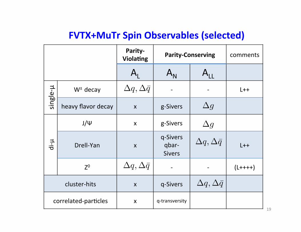
Parity-‐ViolaDng Parity-‐Conserving comments
AL AN ALL
single-‐μ W± decay -‐ -‐ L++
heavy flavor decay x g-‐Sivers
di-‐μ
J/Ψ x g-‐Sivers
Drell-‐Yan x q-‐Sivers qbar-‐Sivers
L++
Z0 -‐ -‐ (L++++)
cluster-‐hits x q-‐Sivers
correlated-‐par?cles x q-‐transversity
∆q,∆q̄
∆q,∆q̄
∆q,∆q̄
∆g
∆g
∆q,∆q̄
FVTX+MuTr Spin Observables (selected)
19

FVTX can beper isolate Drell-‐Yan pairs in di-‐muon events
20
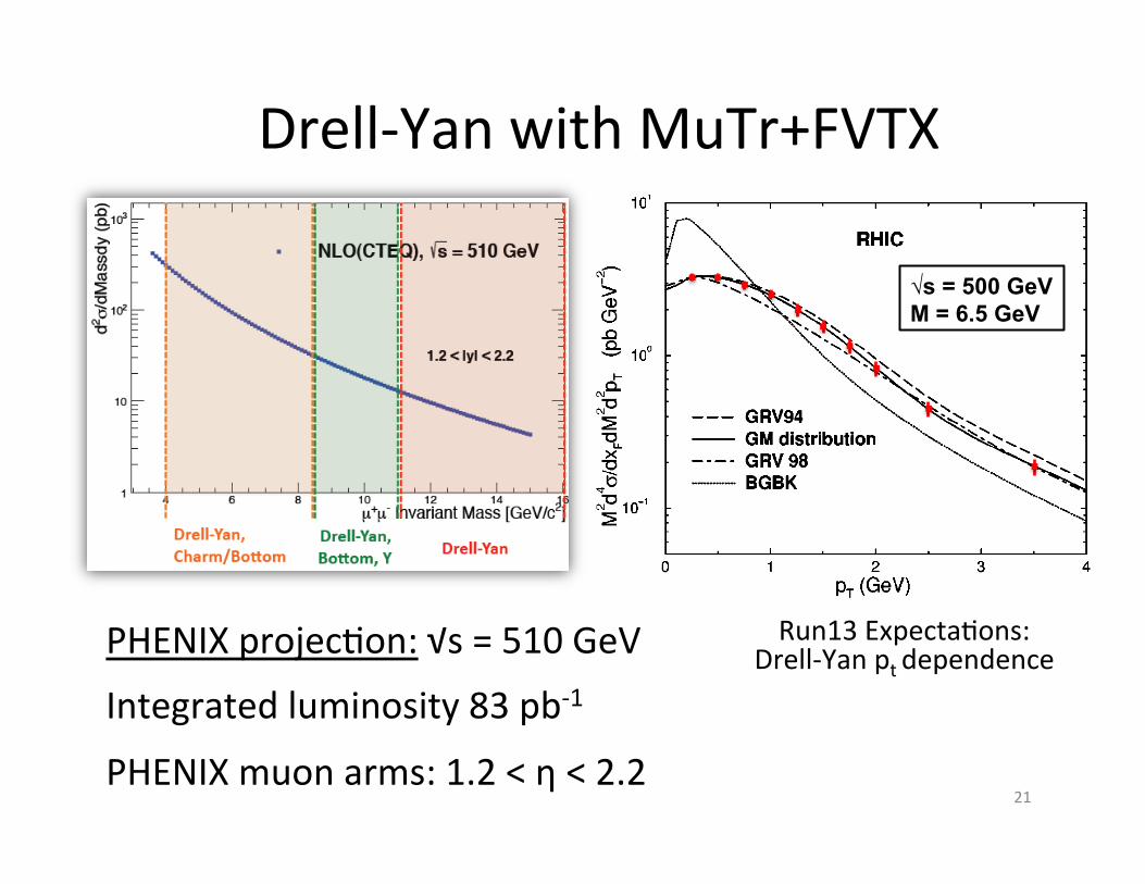
Drell-‐Yan with MuTr+FVTX
PHENIX projec?on: √s = 510 GeV
Integrated luminosity 83 pb-‐1
PHENIX muon arms: 1.2 < η < 2.2 21
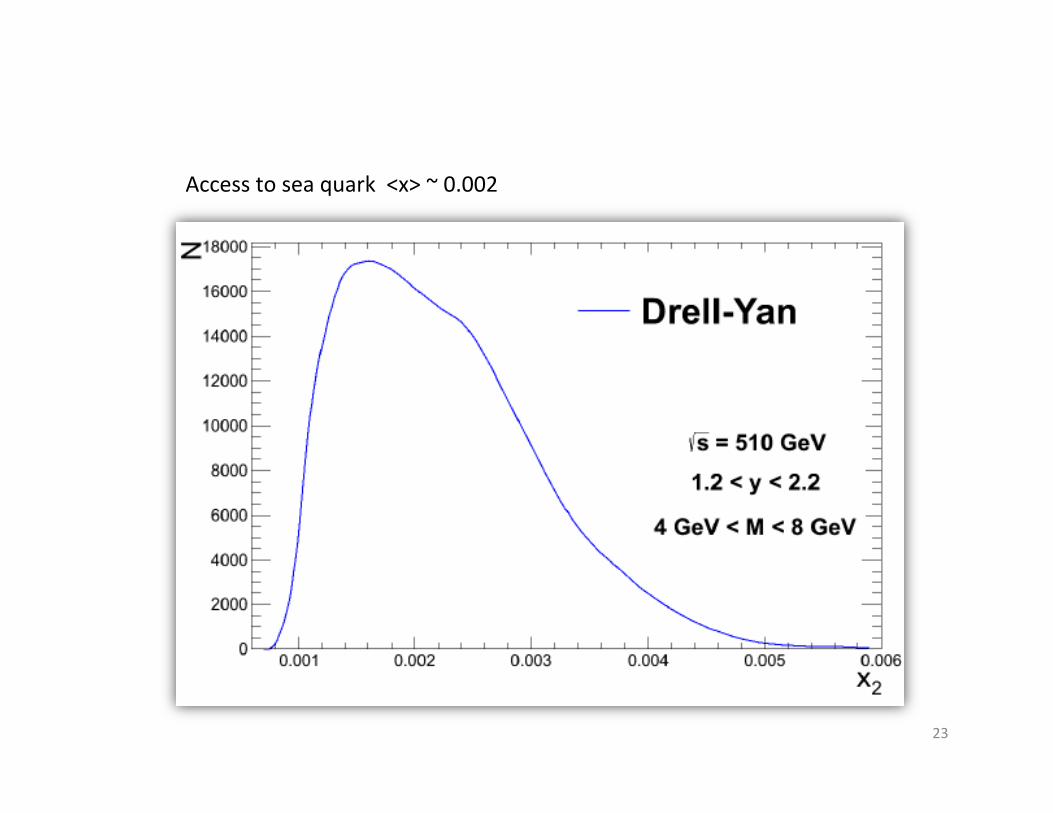
!s = 500 GeV M = 6.5 GeV
Run13 Expecta?ons: Drell-‐Yan pt dependence
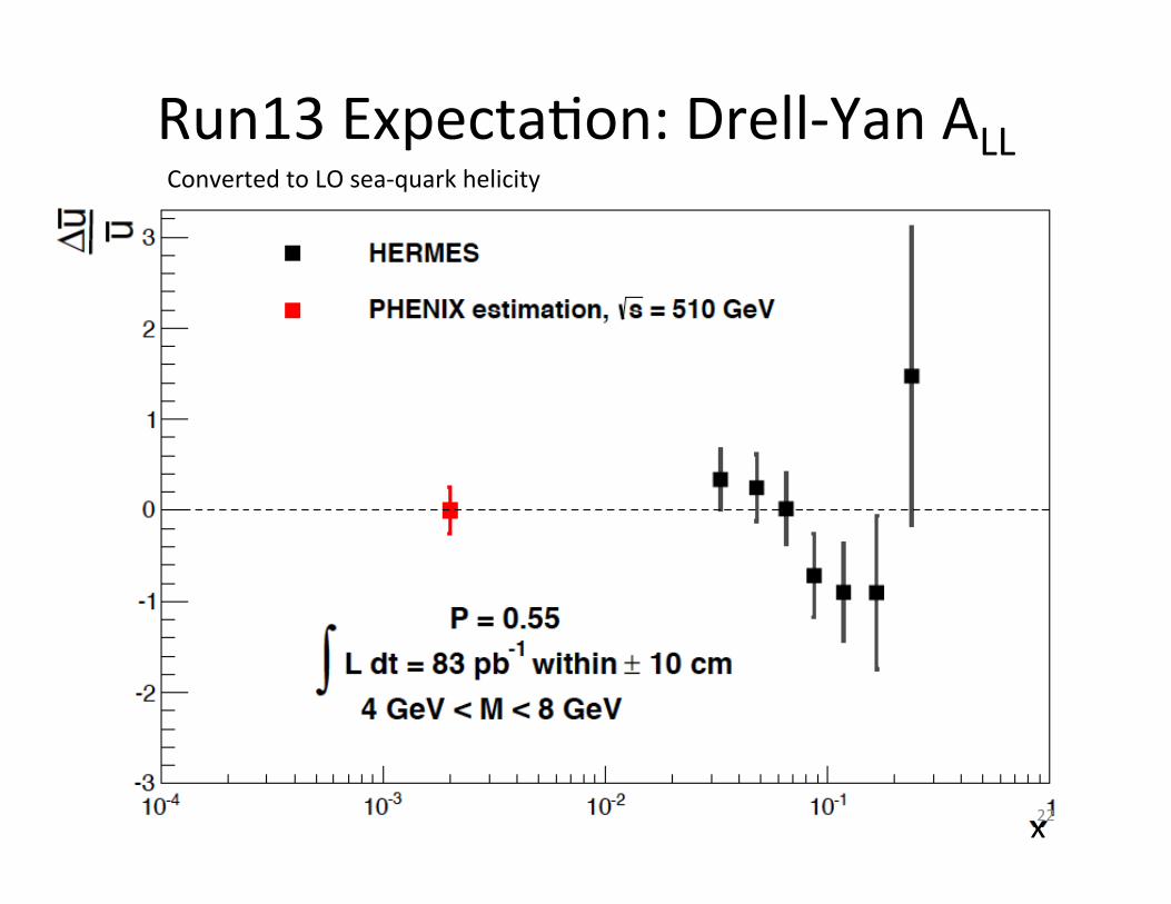
Run13 Expecta?on: Drell-‐Yan ALL
x
Converted to LO sea-‐quark helicity
22
23
Access to sea quark <x> ~ 0.002

Run13 Expecta?on: Drell-‐Yan ALU
arxive:1108.4974 (Lu, Ma, Zhu)
projecDon
24
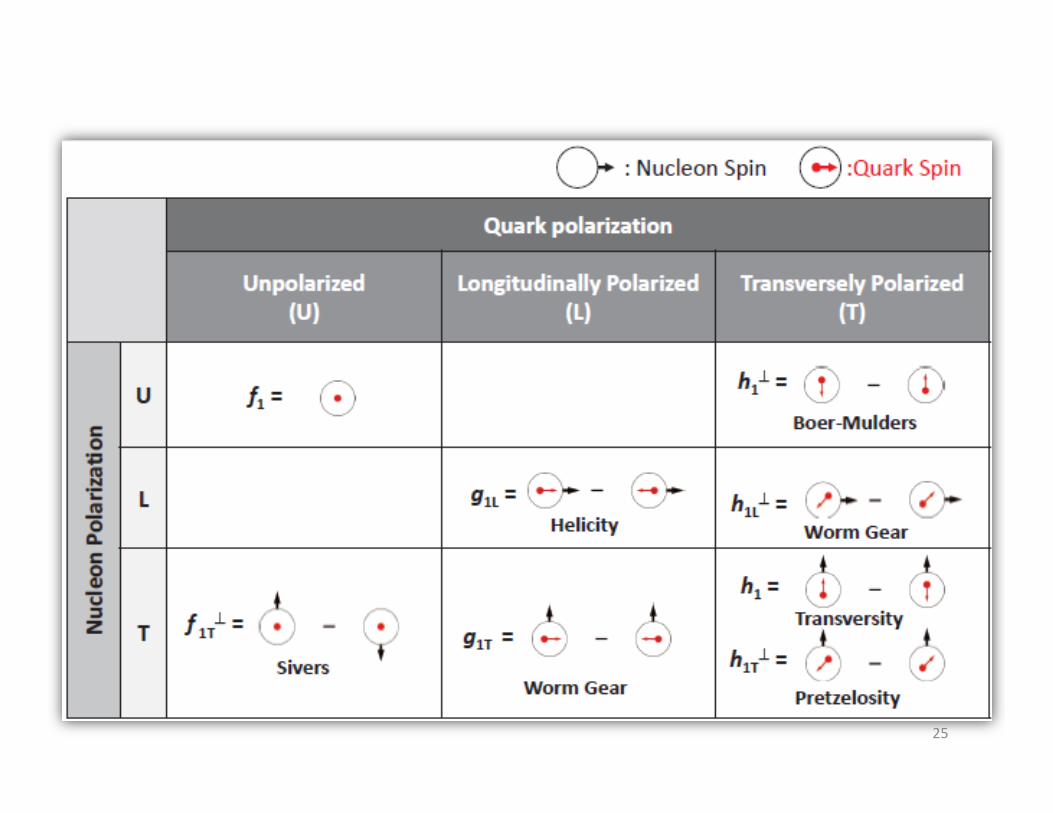
Access to quark “longitudinal-‐transversity” (one of 8-‐TMDs) Transverse quark polariza?on in a longitudinally polarized nucleon.
25

26
PHENIX Beyond Run14: The MPC-‐EX Detector A combined charged par?cle tracker and EM preshower detector – dual gain readout allows sensi?vity to MIPs and full energy EM showers. • π0 rejec?on (direct photons) • π0 reconstruc?on out to >80GeV • Charged track iden?fica?on
3.1<η<3.8
To be ready for Run-‐14
BNL Internal Review on May 11th, 2012.
27
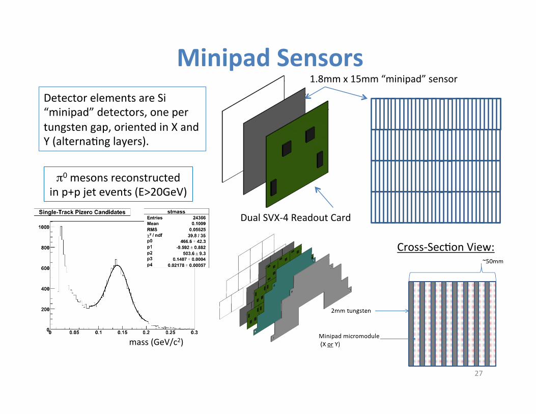
Minipad Sensors
π0 mesons reconstructed in p+p jet events (E>20GeV)
mass (GeV/c2)
1.8mm x 15mm “minipad” sensor
Dual SVX-‐4 Readout Card
Cross-‐Sec?on View:
Detector elements are Si “minipad” detectors, one per tungsten gap, oriented in X and Y (alterna?ng layers).
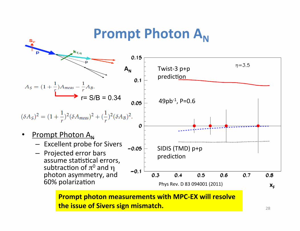
AN
xF
• Prompt Photon AN – Excellent probe for Sivers – Projected error bars
assume sta?s?cal errors, subtrac?on of π0 and η photon asymmetry, and 60% polariza?on
28
Prompt Photon AN
49pb-‐1, P=0.6
Twist-‐3 p+p predic?on
SIDIS (TMD) p+p predic?on
Prompt photon measurements with MPC-‐EX will resolve the issue of Sivers sign mismatch.
r= S/B = 0.34
Phys Rev. D 83 094001 (2011)
29
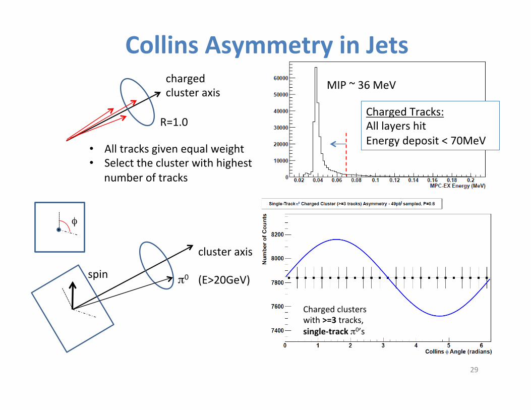
Collins Asymmetry in Jets charged cluster axis
R=1.0
• All tracks given equal weight • Select the cluster with highest
number of tracks
MIP ~ 36 MeV
Charged Tracks: All layers hit Energy deposit < 70MeV
Charged clusters with >=3 tracks, single-‐track π0’s
cluster axis
spin π0
φ
(E>20GeV)
Conclusions Run12 transverse p+p 200 GeV data: • π0, η SSA from MPC data. • Correlated-‐hadron SSA.
Run12 had many new developments beyond W-‐physics: • FVTX commissioned, • Heavy Flavor single-‐muon trigger.
Run13 expect the first polarized Drell-‐Yan data set (longitudinal) • Double-‐spin asymmetry ALL • Single-‐spin asymmetry ALU
Beyond Run14 • MPC-‐EX
30