Embed Size (px)
Citation preview

1. Review
1.1. Target board
1.2. Target board The target board has the following block diagram
FPGA
RAM
FLASH SPI
FLASH BPI
RS232_PC
RS232_ST
JTAG_FPGA
TS_INTS_OUT
DVB-T Mod
• FPGA: Spartan 3A FPGA family (3A400). It will be configured with an internal MicroBlaze processor with uClinux embedded
• DVB-T Mod: OFDM modulator • RAM: 64Mbit RAM • FLASH BPI: Parallel Flash used for bitstream, bootloader, uClinux and SW
application • FLASH SPI: Serial Flash not used • RS232_PC: Uart used for PC terminal • RS232_ST: Uart used for communication with ST5518 processor • JTAG_FPGA: JTAG used for download/debug data to FPGA and for writing
code to FLASH_BPI • JTAG_SPI: JTAG used for download data to SPI • TS_IN: Input transport stream • TS_OUT: Output transport stream

The FPGA has to be configured internally with the following HW structure:
Uart_Mod
Uart_PC
Uart_ST
Timer
Clock Watchdog
Interrupt
uBlaze
TS switch
GPIO
RAM controller
SPI controller
BPI controller
1.3. SW platform The FPGA must be configured in HW as a Microprocessor downloading the code as a bitstream. Inside the bitstream there’s the bootloader code, which will perform the boot from Flash Memory. The boot loads the uClinux and executes it. After OS booting, the SW application is launched and the board is ready to work.
FPGA
Bitstream
Bootloader
uClinux
Application SW
The boot process is the following:
• After power on the board the FPGA starts downloading the bitstream from the BPI memory (selected by the M0, M1 and M2 switches)
• The bitstream contains both the Microblaze configuration and the first application that starts automatically (the application is compiled in BRAMs bits inside the FPGA structure). The bootloader points to uClinux image in Flash BPI memory and copies all the kernel and ROM filesystem into the RAM.
• After they are copied into the RAM, the bootloader starts executing the lernel from RAM.
• The kernel mounts the ROMFS into RAM and it is configured with a start SW application.
• After kernel starts executes automatically the SW application.
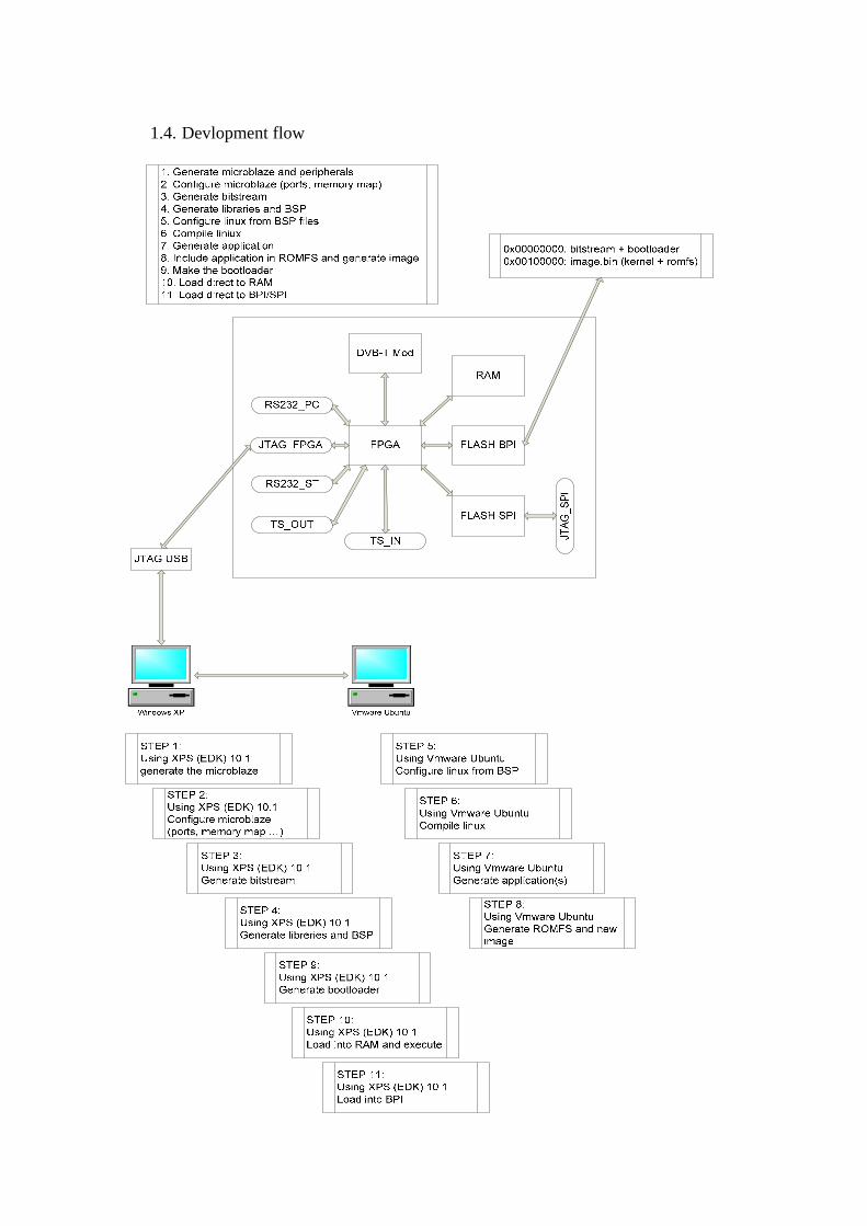
1.4. Devlopment flow
2. Required HW
2.1. PC requirements
• USB 2.0 port • RS232 port • 2 GB RAM
2.2. Tools
• Xilinx Platform Cable USB II
3. Required SW
• ISE webpack 10.1 (ISE, EDK, iMPACT) • Vmware Workstation 6.5
4. SW installation
4.1. TBD 4.2. TBD
5. XPS setup
5.1. TBD 5.2. TBD
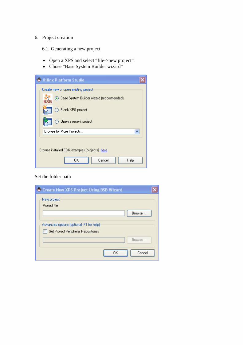
6. Project creation
6.1. Generating a new project
• Open a XPS and select “file->new project” • Chose “Base System Builder wizard”
Set the folder path

• Chose “I would like to create a new design”

Set the “I would like to create a system for custom board
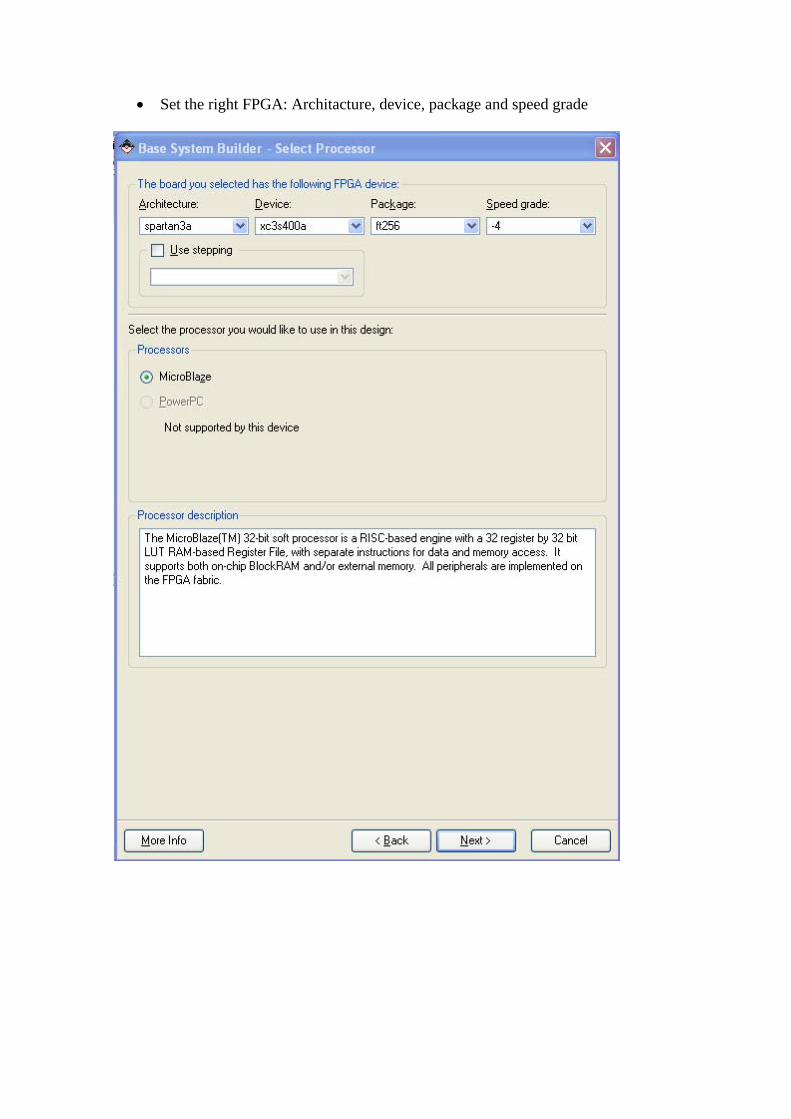
• Set the right FPGA: Architacture, device, package and speed grade

• Set the clock frequency, the bus frequency (the FPGA can generate any bus frequency from any reference clock due to internal DCMs). Select the On-chip H/W debug module” for development. Set the BRAM to 8K and enable cache setup

• Add a “Geenric_External_Memory” controller (XPS_MCH_EMC). Set the Memory size to 8Mb, 8-bit data width and asynchronous type
• Add a “RS232” controller (XPS_UARTLITE). Set the baud rate to 115200, 8bits, no parity and use interrupt (for PC terminal)

• Add a “RS232” controller (XPS_UARTLITE). Set the baud rate to 9600, 8bits, no parity and use interrupt (for ST communication)
• Add a “RS232” controller (XPS_UARTLITE). Set the baud rate to 115200, 8bits, no parity and use interrupt (for Modulator communication)

• Add a “Generic_SPI” controller (XPS_SPI). Set the paramenters as following:

• Set the cache setup at 4KB for both ICache (instruction cache) and DCache (data cache) and map them on Generic_External:Memory (SRAM)
• Set the STDIN and STDOUT (PC terminal) to RS232, and the boot memory to ilmb_cntlr.
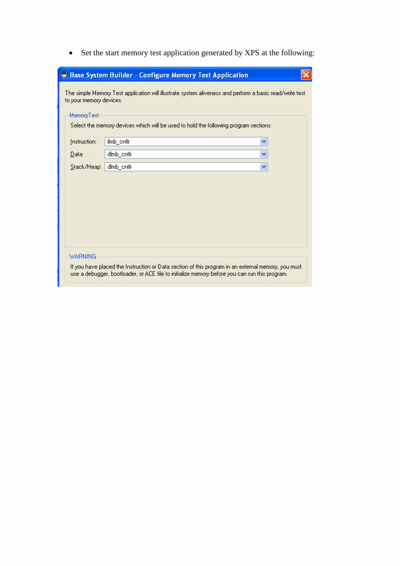
• Set the start memory test application generated by XPS at the following:
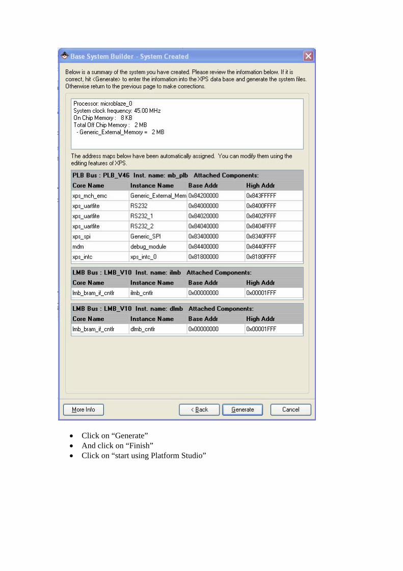
• Click on “Generate” • And click on “Finish” • Click on “start using Platform Studio”
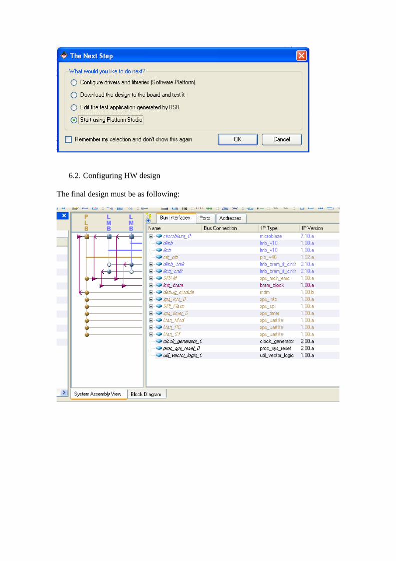
6.2. Configuring HW design The final design must be as following:
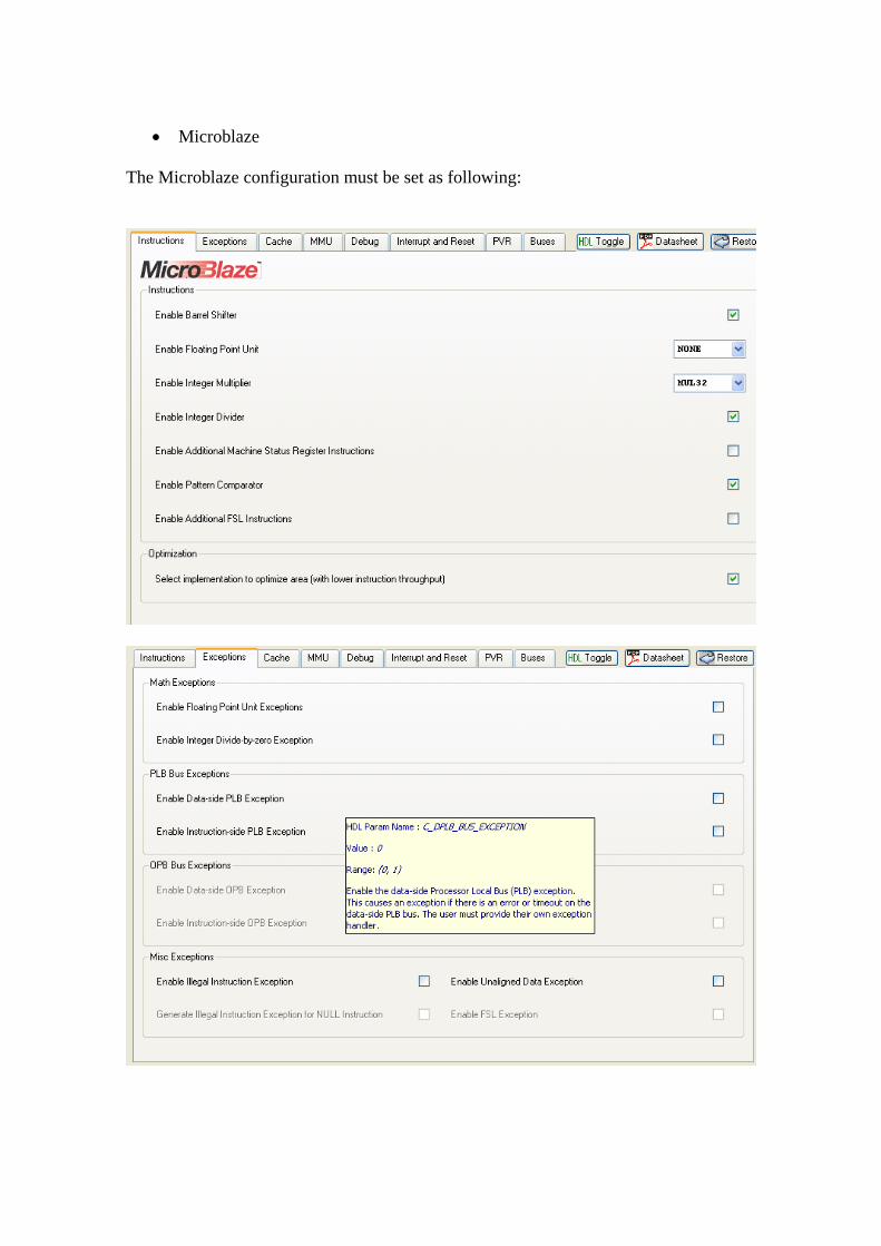
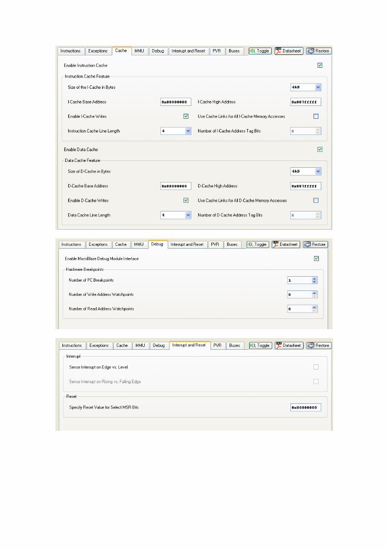
• Microblaze
The Microblaze configuration must be set as following:

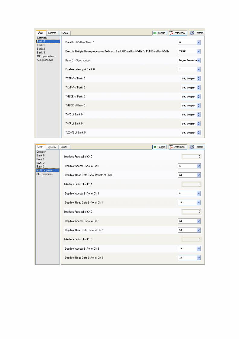
• SRAM The SRAM configuration must be set as following:

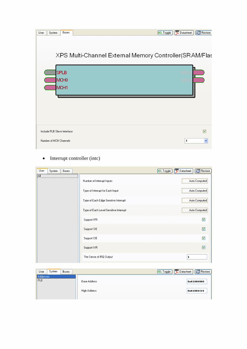
• Interrupt controller (intc)

• Flash SPI
• XPS Timer

• Uart_Mod
• Uart_PC
• Uart_ST
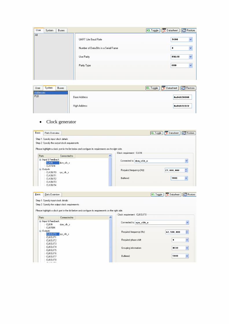
• Clock generator

• Proc_sys_reset
• Vector_logic
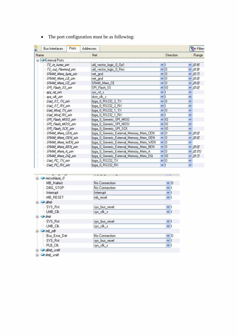
• The port configuration must be as following:


• The address map is as follows:
6.3. Generating BSP files
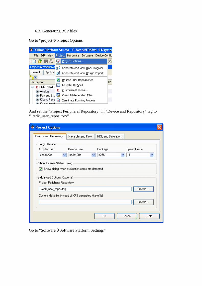
Go to “project Project Options
And set the “Project Peripheral Repository” in “Device and Repository” tag to “../edk_user_repository”
Go to “Software Software Platform Settings”
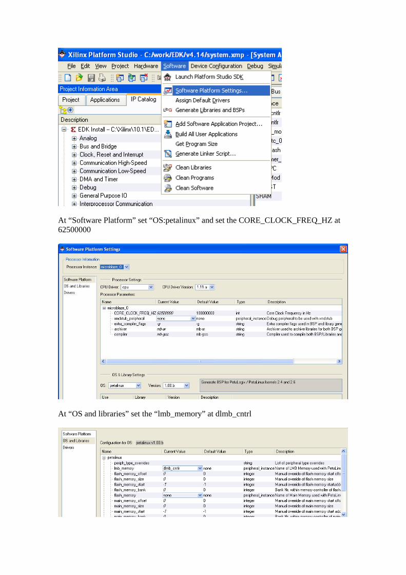
At “Software Platform” set “OS:petalinux” and set the CORE_CLOCK_FREQ_HZ at 62500000
At “OS and libraries” set the “lmb_memory” at dlmb_cntrl

And “main_memory” at SRAM, “stdin” and “stdout” at Uart_PC
Click at “Software Generate Libraries and BSPs”
And the platform will generate the needed file for generating embedded linux. File generated is <Project folder>\microblaze_0\libsrc\petalinux_v1_00_b\Kconfig.auto Click at “Software Build all user applications”

And “memory test” application will be compiled. Click to “Update Bitstream” and application will be added to bitstream at <Project folder>\implementation\download.bit 7. VMware
7.1. asdasd 7.2. dasda
8. Virtual Machine setup
8.1. Configuring virtual machine
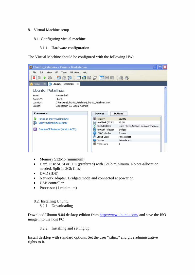
8.1.1. Hardware configuration The Virtual Machine should be configured with the following HW:
• Memory 512Mb (minimum) • Hard Disc SCSI or IDE (preferred) with 12Gb minimum. No pre-allocation
needed. Split in 2Gb files • DVD (IDE) • Network adapter. Bridged mode and connected at power on • USB controller • Processor (1 minimum)
8.2. Installing Ununtu 8.2.1. Downloading
Download Ubuntu 9.04 desktop edition from http://www.ubuntu.com/ and save the ISO image into the host PC
8.2.2. Installing and setting up Install desktop with standard options. Set the user “xilinx” and give administrative rights to it.
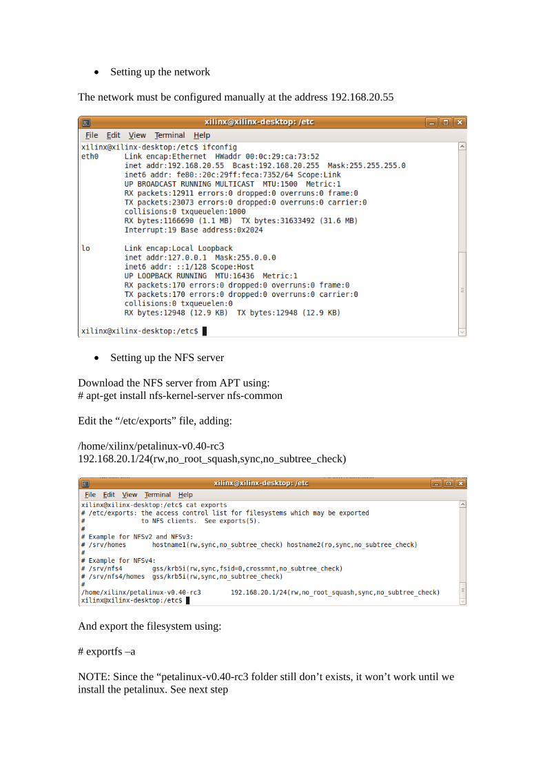
• Setting up the network The network must be configured manually at the address 192.168.20.55
• Setting up the NFS server Download the NFS server from APT using: # apt-get install nfs-kernel-server nfs-common Edit the “/etc/exports” file, adding: /home/xilinx/petalinux-v0.40-rc3 192.168.20.1/24(rw,no_root_squash,sync,no_subtree_check)
And export the filesystem using: # exportfs –a NOTE: Since the “petalinux-v0.40-rc3 folder still don’t exists, it won’t work until we install the petalinux. See next step

8.3. Downloading and installing Petalinux
8.3.1. Downloading
Download latest version of Petalinux from http://developer.petalogix.com/ (tested with petalinux-v0.40-rc3)
8.3.2. Installing Copy the “petalinux-v0.40-rc3tar.gz” file into the ~/home/Xilinx folder. Uncompress it using: # tar –zxvf petalinux-v0.40-rc3.tar.gz
9. Generating Linux
9.1. Environment Open a bash shell from user’s home folder. There must be a folder named “petalinux-v0.40-rc3”. Type “cd petalinux-v0.40-rc3” and “source settings.sh” to set the environment variables. All shells opened to perform any instruction with petalinux must be started with the environment variables
9.2. Setting up the HW platform From the bash shell, type “petalinux-new-platform –v Engel –k 2.6 –p Spartan3A400-rev00”. Scripts will generate folders with the platform information
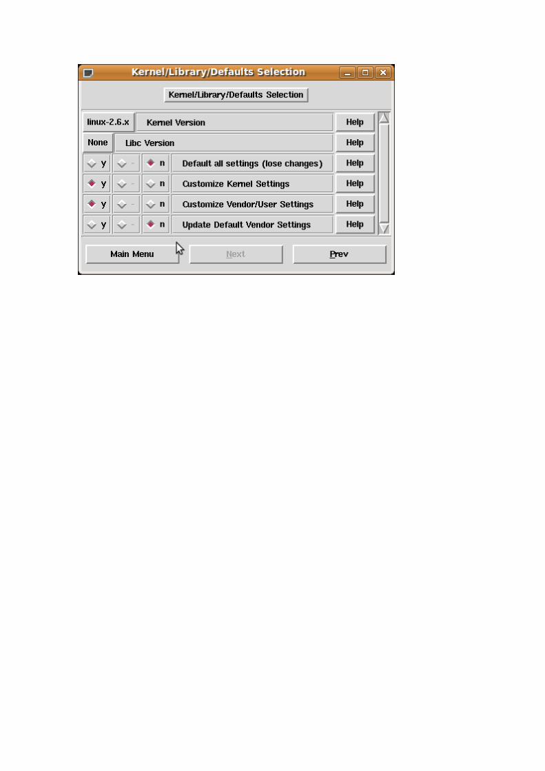
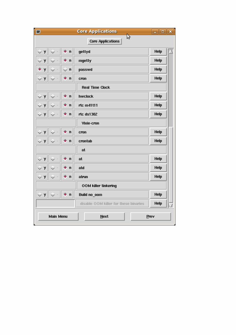
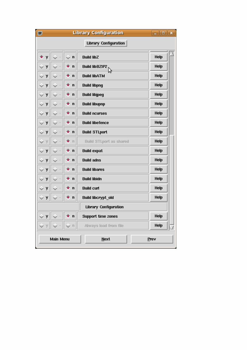
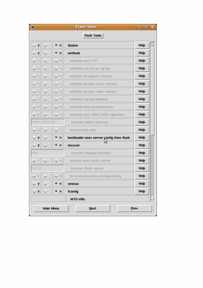
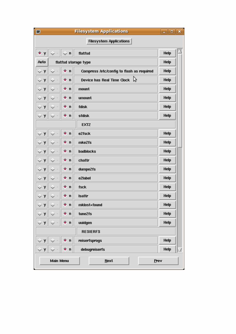
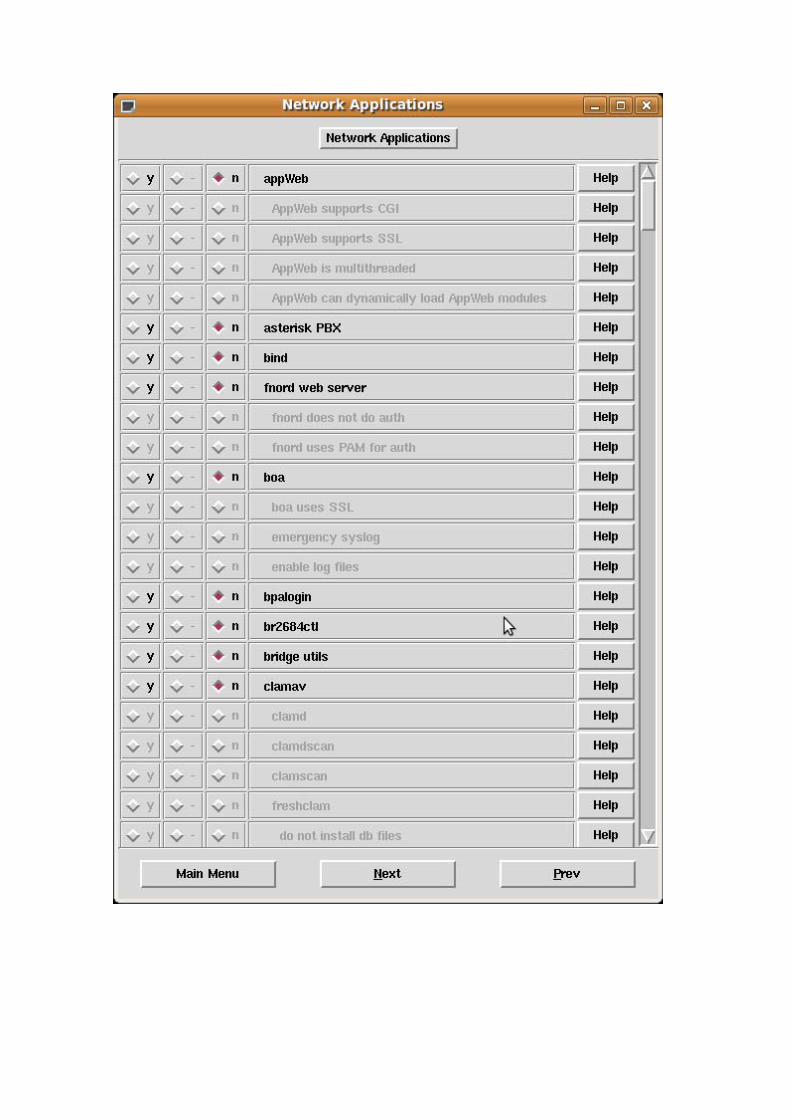
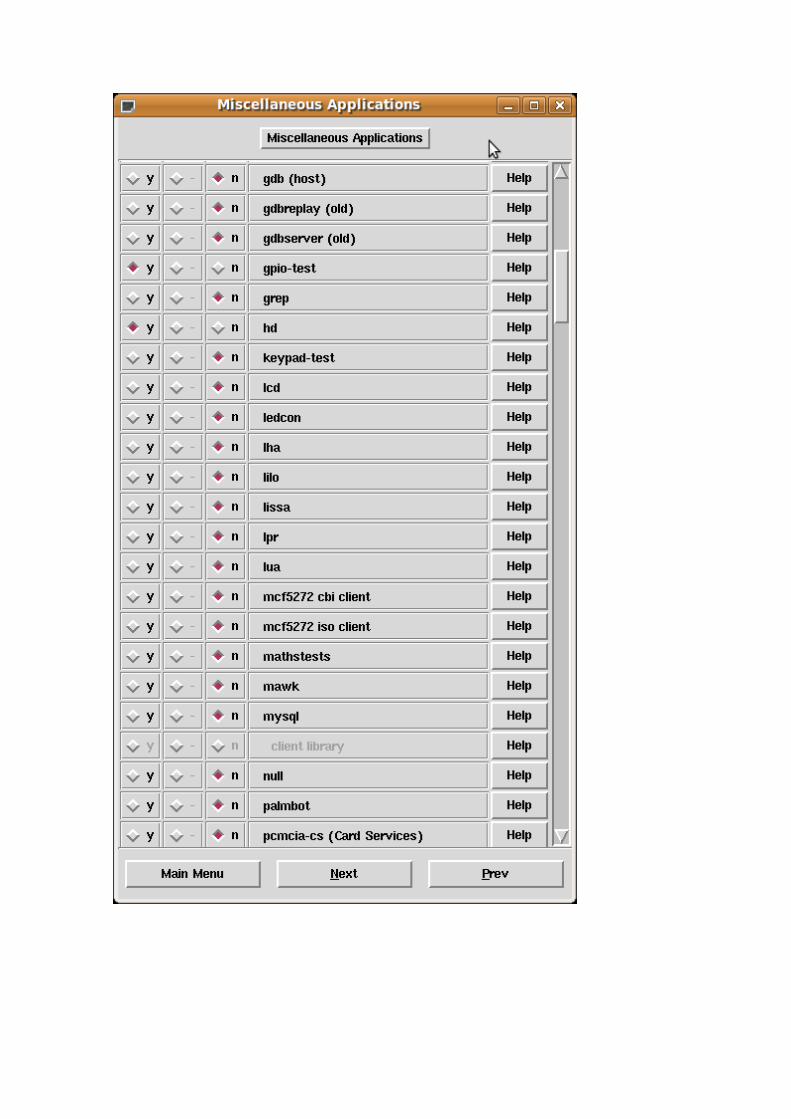
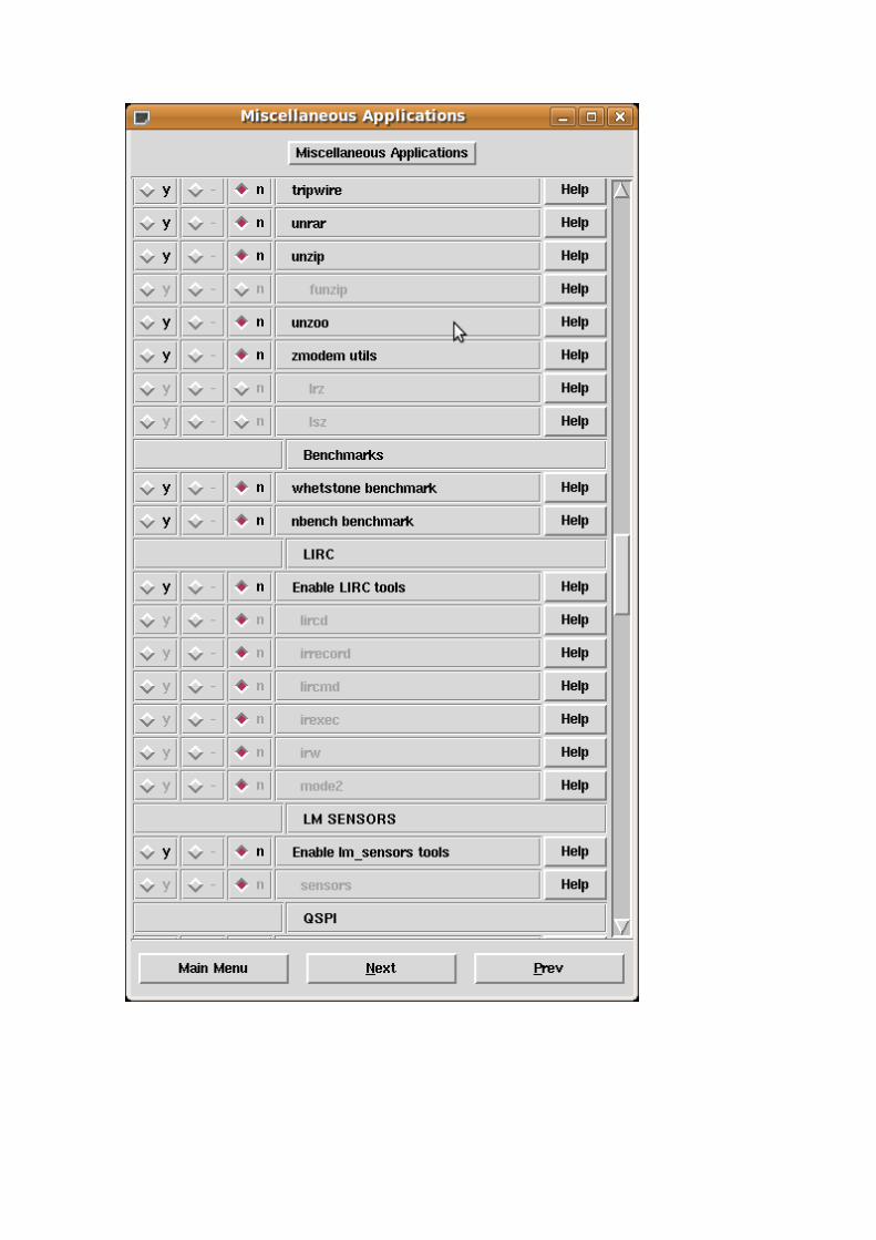
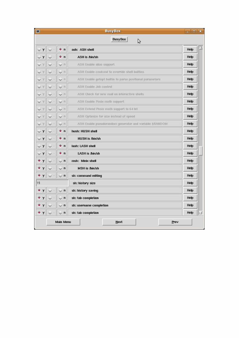
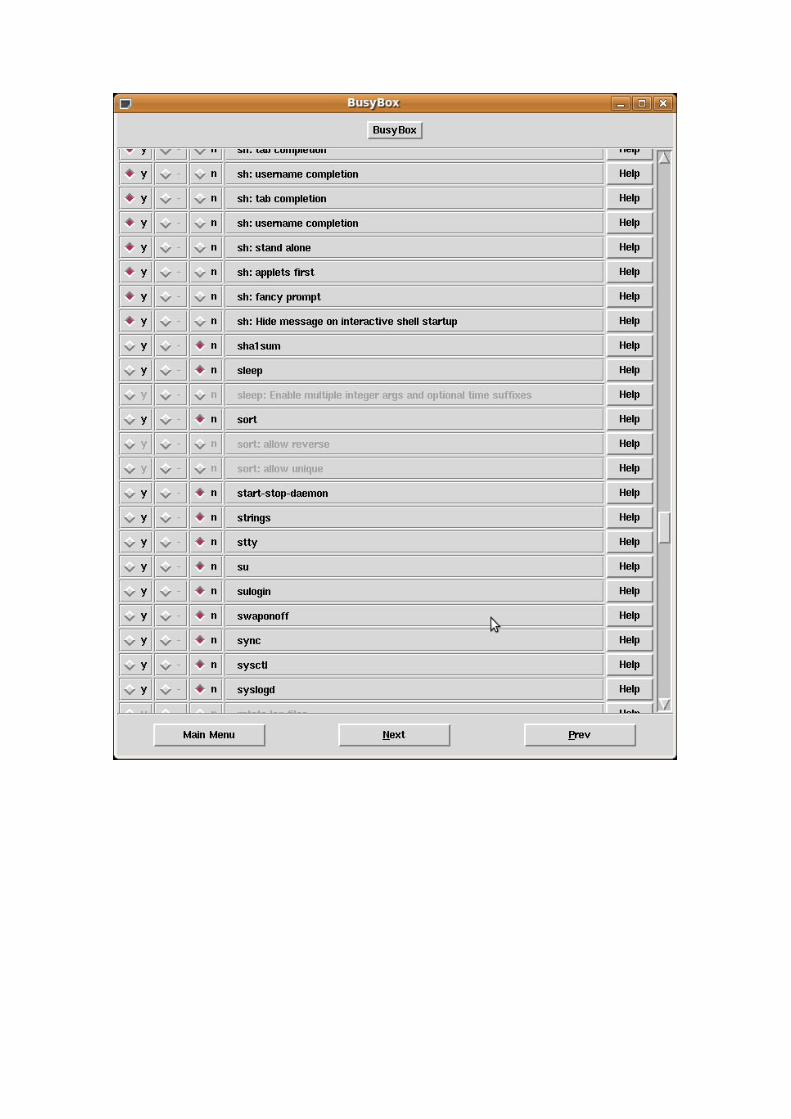
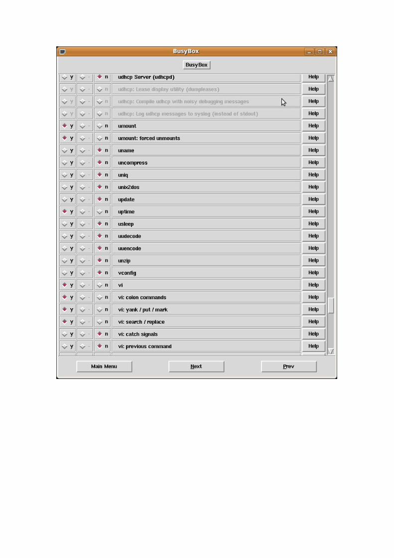
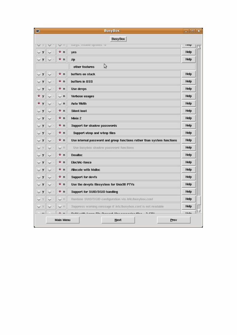
9.3. Configuring kernel settings
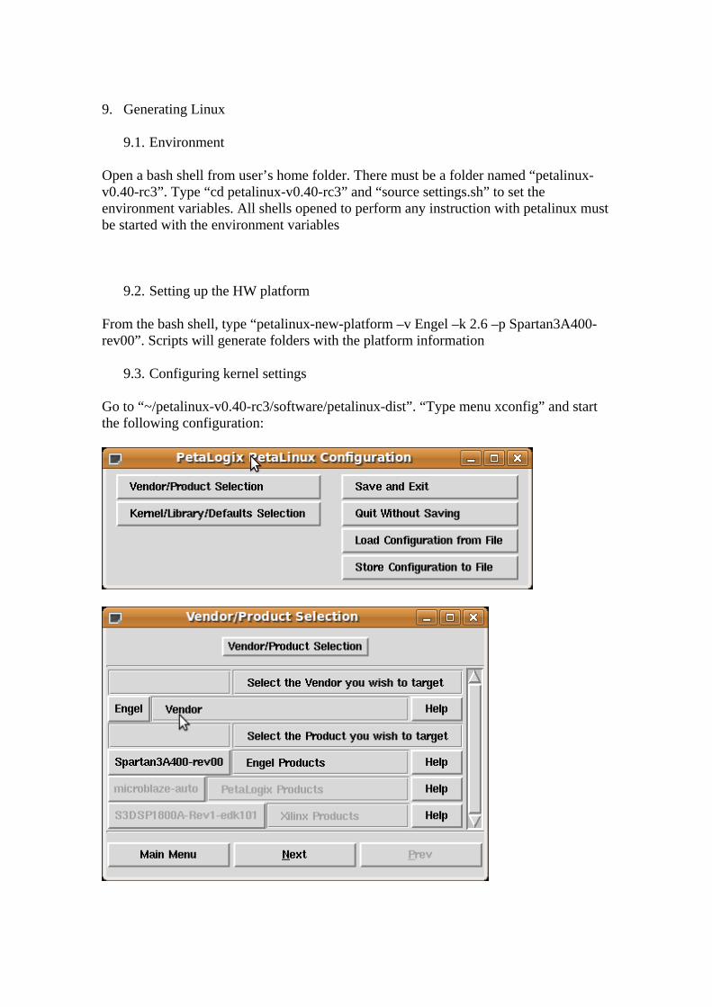
Go to “~/petalinux-v0.40-rc3/software/petalinux-dist”. “Type menu xconfig” and start the following configuration:


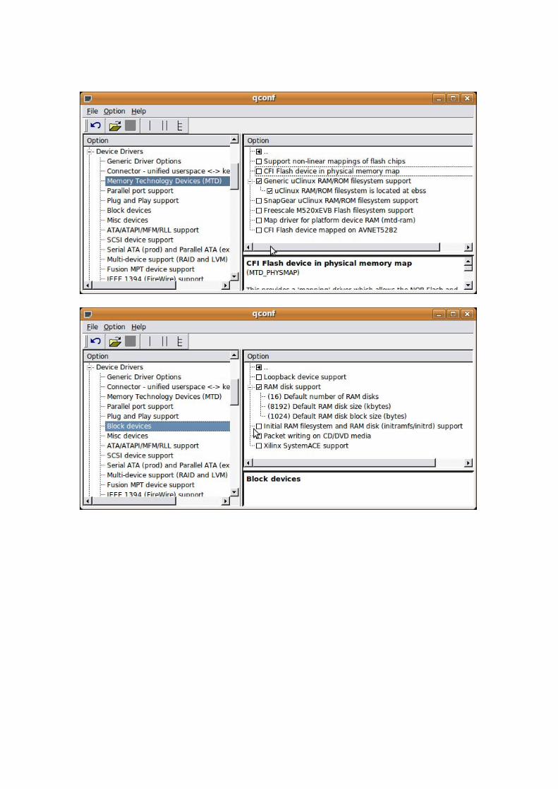
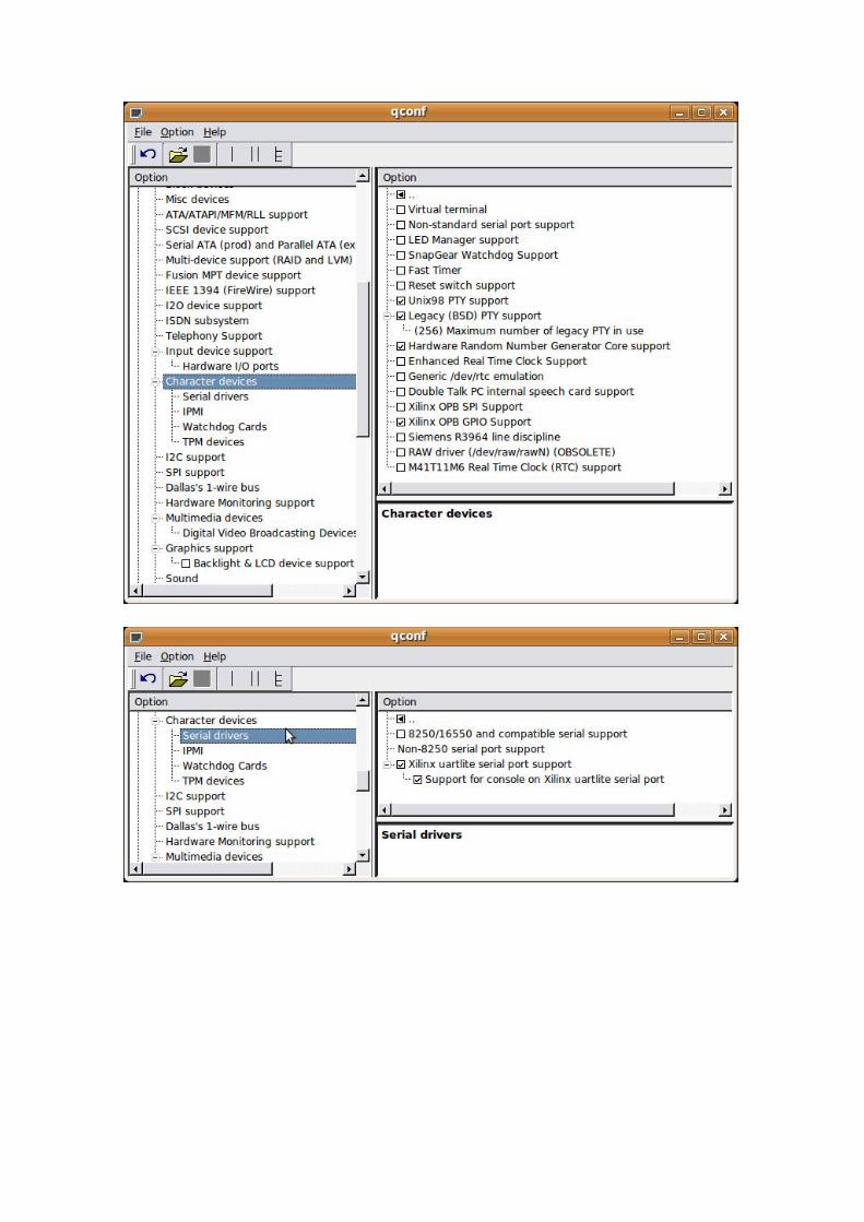
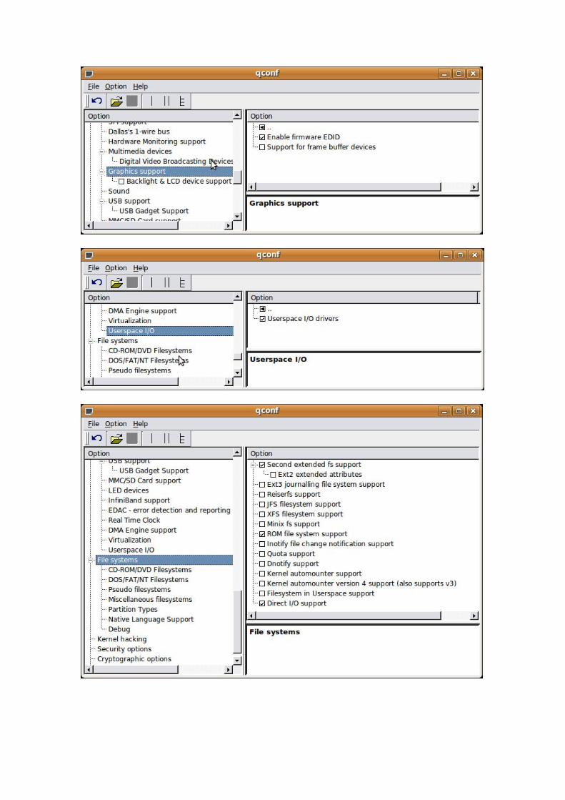

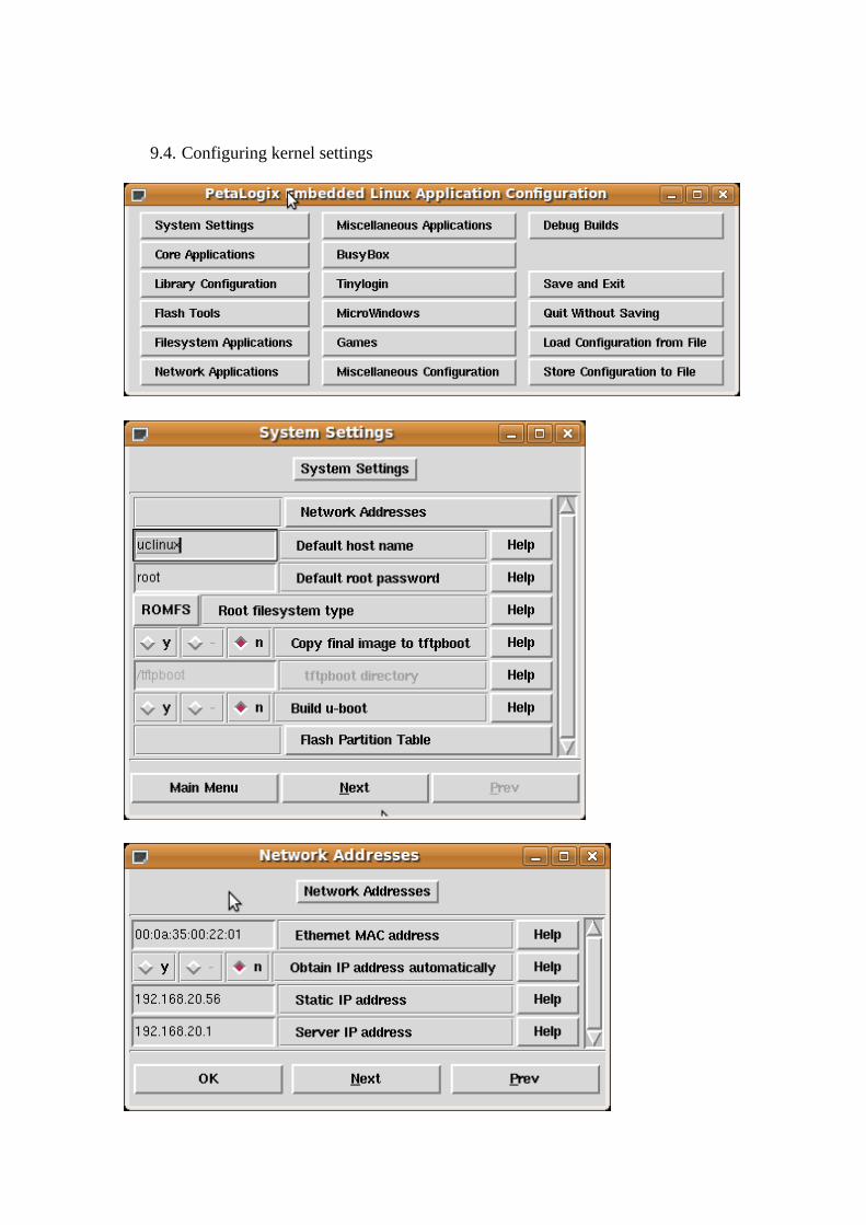
9.4. Configuring kernel settings


9.5. Compiling After saving the configuration, type “make all” in the bash shell. It must compile all the the kernel with the selected options and it will generate both ROM filesystem and Kernel Image.
9.6. Folder trees The following folders are generated with the following information (all included in ~/petalinux-v0.40-rc3/software/petalinux-dist):
• Folder bin/ o image.bin kernel + filesystem to be downloaded to target
(recommended) o image.elf kernel + filesystem in elf format o linux.bin kernel binary (can be alternate loaded with romfs image
instead image.bin) o romfs.img romfs image (can be alternate loaded with kernel binary
instead image.bin) • Folder romfs/
This folder contains all original filesystem (compressed into romfs.img and inage.bin). It has the usual System V structure
o bin/ binary files o dev/ devices nodes o etc/ configuration and init files o and so on.....
9.7. Suitable configurations The “make all” instruction executed previously generates the kernel according the configuration options, generates also the romfs and the images. If any configuration from rom filesystem file must be modified manually, after doing it so it’s needed generating again the image file. So from “~/petalinux-v0.40-rc3/software/petalinux-dist” folder type “make image”. From current romfs folder it will generate all the images. If needed generating again the romfs without compiling again the kernel, the user could perform “make romfs” from “~/petalinux-v0.40-rc3/software/petalinux-dist”. After this romfs generation, it must be generated again the image with “make image”

10. Running Linux from RAM
10.1. Conection
• RS232
• Platform Cable USB II
10.2. Folders and files
• Project files and tools
Copy the compiled image.bin file from Ubuntu folder “~/petalinux-v0.40-rc3/software/petalinux-dist/images” to the “c:\work\EDK\xxxx” project folder The “c:\work\EDK\xxxx” project folder must contain at least the updated XPS project, updated SW and bitstream (“c:\work\EDK\xxxx\implementation\download.bit”) There must be the file “c:\work\EDK\xxxx\etc\download.cmd” with the following commands:
There must be the file “c:\work\EDK\Misc\xmd_pl.bat” with the following commands:

10.3. Downloading Open a Hyperterminal session, with 115200, 8, N, 1. Open a cmd window. Go to project “cd \work\EDK\xxxx” and type “..\Misc\xmd_pl.bat” The batch will start first downloading the microblaze “download.bit” from the current project:
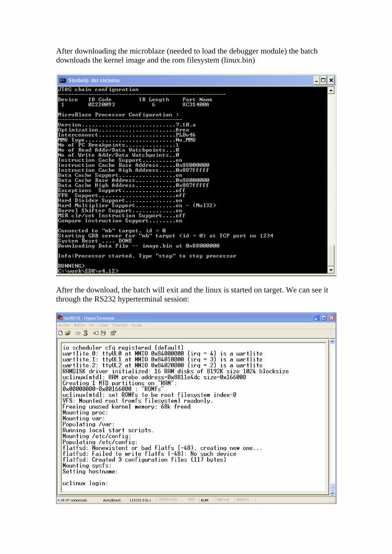
After downloading the microblaze (needed to load the debugger module) the batch downloads the kernel image and the rom filesystem (linux.bin)
After the download, the batch will exit and the linux is started on target. We can see it through the RS232 hyperterminal session:

10.4. Executing
Now the linux is loaded ito SRAM. Through the Hyperterminal we can work normally with the target. First we must enter the user (root) and password (root)

11. Booting and running Linux from Flash BPI
11.1. Requirements In the project folder there must be the following files and folders:
• BPI_bootloader folder:
• FLASH_BURN folder
• Pllinux_images folder (no files needed)

11.2. Downloading the Bitstream
With the current application (without any bootlooader) download the microblaze core to the board
11.3. Adding the bootloader application In the XPS Project, select the Applications tab and double-click on Add software Application

Enter BPI_Bootloader in the Project name
Add the project source code double-clicking in Sources
Use the browser to add the “bootload.c” and “SF_commands.c” files

Add the header files

Browsing into the folder

Modifying bootloader Edit “bootloader.c” file. Go to following constants and modify the KDI_LENGTH according “image.bin” file length
To do so, go to the “image.bin” file, click on properties and check the size

In this case, the size is 3481780, so 0x3520B4
11.4. Building the application Unmark the “TestApp_Memory” application for BRAM inizialization

Mark the “BPI_Bootloader” application for BRAM inizialization
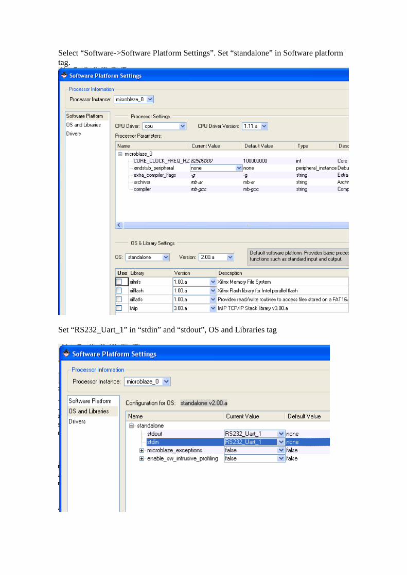
Select “Software->Software Platform Settings”. Set “standalone” in Software platform tag.
Set “RS232_Uart_1” in “stdin” and “stdout”, OS and Libraries tag
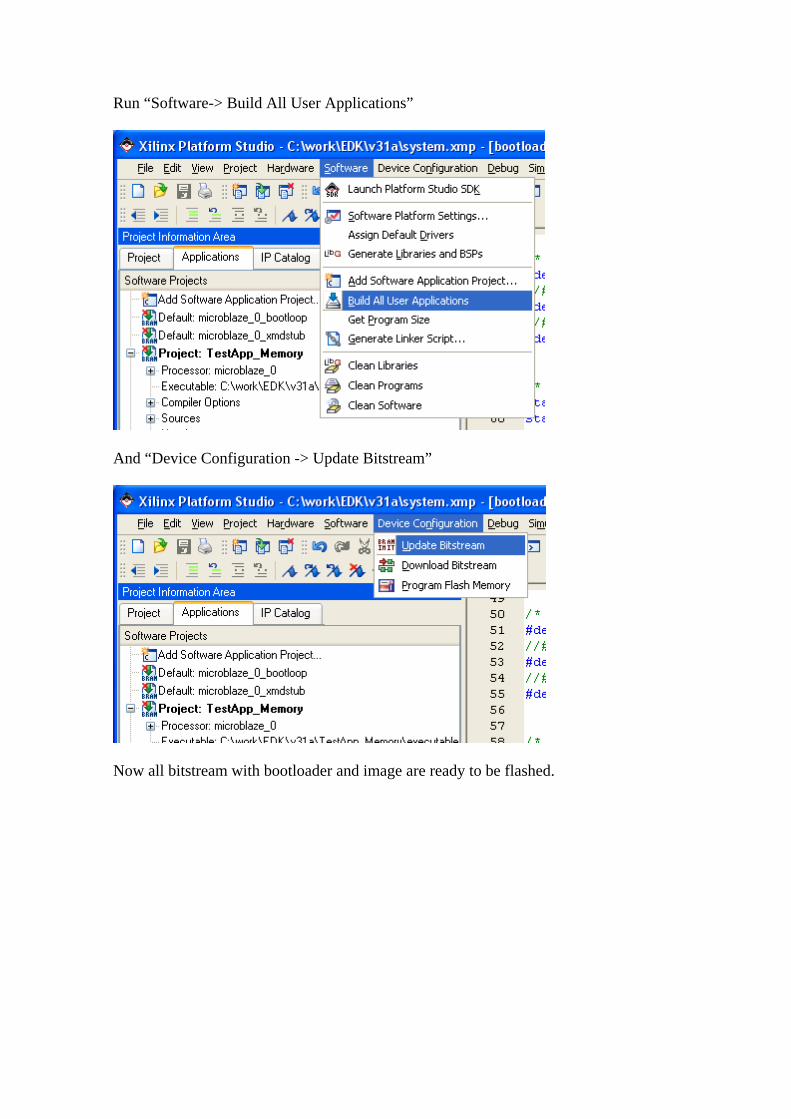
Run “Software-> Build All User Applications”
And “Device Configuration -> Update Bitstream”
Now all bitstream with bootloader and image are ready to be flashed.
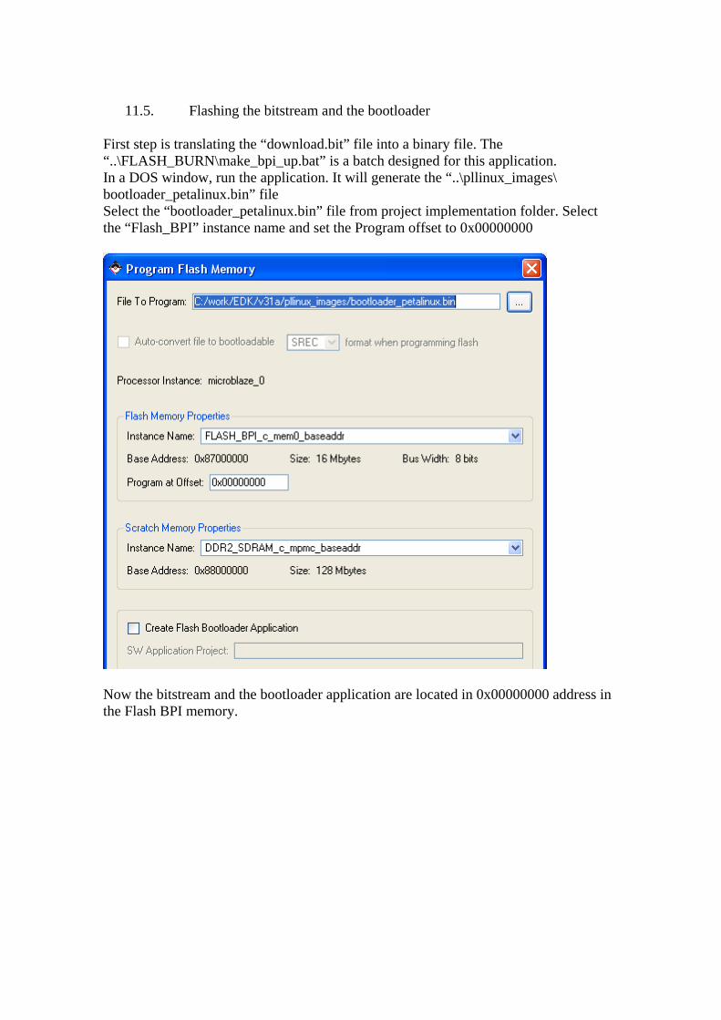
11.5. Flashing the bitstream and the bootloader
First step is translating the “download.bit” file into a binary file. The “..\FLASH_BURN\make_bpi_up.bat” is a batch designed for this application. In a DOS window, run the application. It will generate the “..\pllinux_images\ bootloader_petalinux.bin” file Select the “bootloader_petalinux.bin” file from project implementation folder. Select the “Flash_BPI” instance name and set the Program offset to 0x00000000
Now the bitstream and the bootloader application are located in 0x00000000 address in the Flash BPI memory.
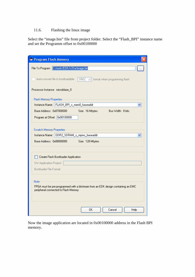
11.6. Flashing the linux image
Select the “image.bin” file from project folder. Select the “Flash_BPI” instance name and set the Programm offset to 0x00100000
Now the image application are located in 0x00100000 address in the Flash BPI memory.

11.7. Booting from Flash
Turn of the board. Set the “M0 & M2” on. Turn on the board and it boots from Flash BPI memory